

Ø150MM/200MM BENCH GRINDER VARIABLE
SPEED
MODEL NO: BG150WVS & BG200WVS
Thank you for purchasing a Sealey product. Manufactured to a high standard, this product will, if used according to these
instructions, and properly maintained, give you years of trouble free performance.
IMPORTANT: PLEASE READ THESE INSTRUCTIONS CAREFULLY. NOTE THE SAFE OPERATIONAL REQUIREMENTS, WARNINGS & CAUTIONS. USE
THE PRODUCT CORRECTLY AND WITH CARE FOR THE PURPOSE FOR WHICH IT IS INTENDED. FAILURE TO DO SO MAY CAUSE DAMAGE AND/OR
PERSONAL INJURY AND WILL INVALIDATE THE WARRANTY. KEEP THESE INSTRUCTIONS SAFE FOR FUTURE USE.
1. SAFETY
1.1. ELECTRICAL SAFETY
WARNING! It is the user’s responsibility to check the following:
9 Check all electrical equipment and appliances to ensure that they are safe before using. Inspect power supply leads, plugs and all
electrical connections for wear and damage. Sealey recommend that an RCD (Residual Current Device) is used with all electrical
products.
Electrical safety information. It is important that the following information is read and understood:
9 Ensure that the insulation on all cables and on the appliance is safe before connecting it to the power supply.
9 Regularly inspect power supply cables and plugs for wear or damage and check all connections to ensure that they are secure.
Important: Ensure that the voltage rating on the appliance suits the power supply to be used and that the plug is tted with the correct
fuse.
8 DO NOT pull or carry the appliance by the power cable.
8 DO NOT pull the plug from the socket by the cable.
8 DO NOT use worn or damaged cables, plugs or connectors. Ensure that any faulty item is repaired or is replaced immediately by a
qualied electrician.
If the cable or plug is damaged during use, switch off the electricity supply and remove from use.
Ensure that repairs are carried out by a qualied electrician.
1.2. GENERAL SAFETY
WARNING! Disconnect the grinder from the mains power, and ensure the grinding wheels are at a standstill before attempting to
change accessories, service or perform any maintenance.
8 DO NOT use a damaged accessory. Before each use, inspect the accessory such as abrasive wheels for chips and cracks.
8 DO NOT operate the grinder if any parts are damaged or missing as this may cause failure and/or personal injury.
▲ DANGER! DO NOT use a damaged wheel as it is dangerous and may cause damage and/or serious personal injury.
WARNING! Only persons qualified under the “Abrasive Wheels Regulations” and holding a current grinding wheel certificate are to change
or dress grinding wheels. Unplug grinder from mains power and refer to Section “Grinding Wheels” below for details.
9 After inspecting and installing an accessory, position yourself and bystanders away from the plane of the rotating accessory and run the
power tool at maximum no-load speed for one minute. Damaged accessories will normally break apart during this test time.
9 The rated speed of the accessory must be at least equal to the maximum speed marked on the grinder. Accessories running faster
than their rated speed can break and y apart.
9 Never grind on the sides of a grinding wheel. Grinding on the side can cause the wheel to break and y apart.
9 Only use accessories with a diameter and maximum thickness specied in the Specication section of this manual.
9 Bench grinders must always be stable and secure e.g. xed to a bench or the like.
9 Grinding wheels must be correctly mounted and free of defects before use (ring tested).
9 Spark arrestors and work rests must be adjusted frequently so as to compensate for the wear of the wheel.
WARNING! Keep all guards and holding screws in place, tight and in good working order. Check regularly for damaged parts. A guard
or any other part that is damaged should be repaired or replaced before tool is next used. The eye shields are a mandatory fitting when
grinder is used in premises covered by the Health & Safety at Work Act.
9 Distance between the spark arrestor/work rest and the wheel must be kept as small as possible and in any case no greater than 2mm.
9 Worn wheel/s must be replaced when the 2mm gap between the spark arrestor/work rest is no longer able to be maintained.
9 For tools with two spindles: always use the tool with accessories on both spindles in order to limit the risk of contact with the rotating
spindle.
9 Always use the guard, work rest, transparent screen and spark arrestor as required for the accessory(ies).
9 Damaged or deeply grooved wheels must be replaced.
9 Always adjust the work rest so that the angle between the work rest and the tangent of the accessory is always greater than 85°.
9 Grinding wheels must always be handled and stored in the correct manner.
9 Maintain the grinder in good condition and check moving parts alignment regularly.
9 Replace or repair damaged parts. Use recommended parts only. Non-authorised parts may be dangerous and will invalidate the warranty.
9 Locate grinder in a suitable working area, keep area clean, tidy and free from unrelated materials. Ensure adequate lighting.
9 Before each use check grinding wheels for condition. If worn or damaged replace immediately.
WARNING! Always wear approved eye or face protection when operating the grinder.
9 Use breathing protection in accordance with COSHH regulations if fumes or dust pose a hazard. Wear ear defenders if necessary.
BG150WVS BG200WVS Issue 4 (H,1,2,3,5) 22/11/23
Original Language Version
© Jack Sealey Limited
Refer to
instructions
Wear eye
protection
Wear ear
protection
Wear a
protective mask
9 Maintain correct balance and footing. Ensure the floor is not slippery and wear non-slip shoes.
9 Remove ill fitting clothing. Remove ties, watches, rings and other loose jewellery and contain and/or tie back long hair.
9 Keep children and unauthorised persons away from the working area.
8 DO NOT use the grinder for a task it is not designed to perform.
WARNING! DO NOT grind any materials containing asbestos.
8 DO NOT switch on the grinder whilst the wheel is in contact with the workpiece.
8 DO NOT get the grinder wet or use in damp or wet locations or areas where there is condensation.
8 DO NOT use grinder where there are flammable liquids, solids or gases, e.g. paint solvents and including waste wiping or cleaning rags etc.
8 DO NOT touch the workpiece close to the ground surface as it will be very hot. Allow to cool. The workpiece may also be very sharp.
8 DO NOT operate the grinder when you are tired, under the influence of alcohol, drugs or intoxicating medication.
8 DO NOT leave the grinder operating unattended.
When not in use switch off the grinder, disconnect from the mains power supply and clean the machine and working area.
2. INTRODUCTION
Induction motor drive suitable for general use. Supplied with stone guards attached, adjustable eye shields and spark arrestors.
Substantial tool rests, one with angled cut-out assisting effective tool sharpening. Variable speed allows for better control of grinding
and sharpening. Features integral coolant tray for convenient cooling of sharpened/ground item.
3. SPECIFICATION
4. ASSEMBLY
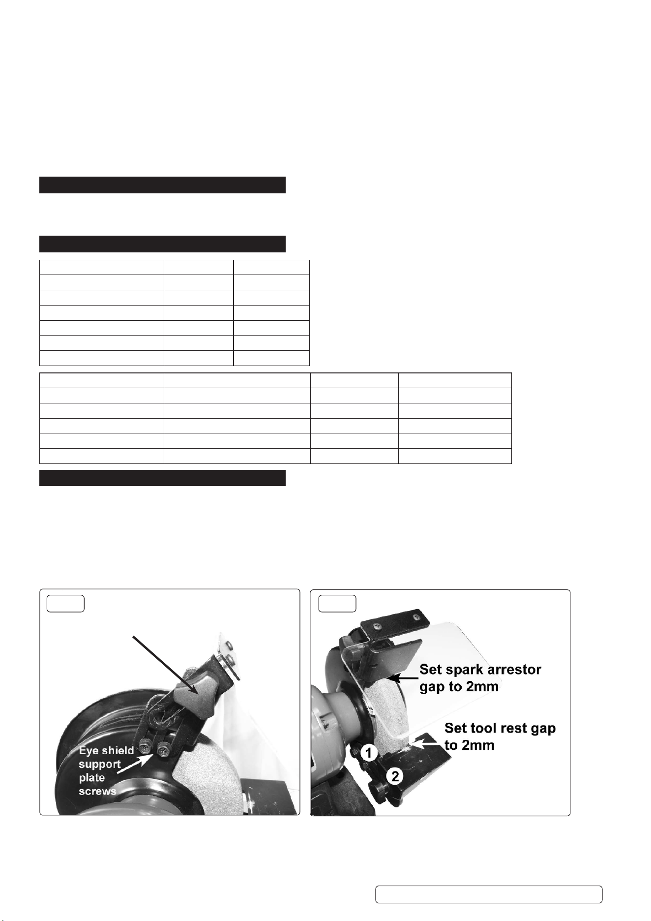
4.1. EYE SHIELD AND COOLANT TRAY
4.1.1. Install the eye shield support plate using the supplied xings to each side of the grinder. See g.1. Adjust the Spark arrestor so the gap
is no more than 2mm between the grinding surface. See g.2. To install the eye shield use the thumb screw supplied. Adjust the eye
shield slide to give maximum protection to the user. See g.1
Install the coolant tray to the front of the grinder. See g.4.
4.2. TOOL REST
4.2.1. Install the tool rest using the xings supplied. See g.2. Use thumb screw 2 to adjust the gap between the grinding surface and the tool
rest. Ensure the tool rest has no more than a gap of 2mm between the grinding surface. See g.2.
Original Language Version
© Jack Sealey Limited
BG150WVS BG200WVS Issue 4 (H,1,2,3,5) 22/11/23
MODEL NO: BG150WVS BG200WVS
Stone size: Ø150mm (x2) Ø200mm (x2)
Motor power: 250W 550W
Supply: 230V 230V
Axle diameter: Ø13mm Ø16mm
No load speed range: 2000-2850rpm 2000-2850rpm
Power Supply Cable Length: 1.6m 1.6m
BG150WVS MAX OVERALL DIAMETER (MM) MAX WIDTH (MM) BORE DIAMETER (MM)
36# 151mm 20.5mm 12.7mm
60# 151mm 20.5mm 12.7mm
BG200WVS
36# 201mm 25.5mm 15.88mm
60# 201mm 25.5mm 15.88mm
g.1 g.2
Eye shield
adjustment
5. GRINDING WHEELS
5.1. MANDATORY SAFETY INSTRUCTIONS. (The following instructions must be observed together with those in Section 1).
▲ DANGER! Use of a damaged wheel (stone) is dangerous and may cause damage and/or personal injury.
WARNING! Ensure grinder is unplugged from mains supply before attempting to change grinding wheel (stone). Only persons qualied
under the “Abrasive Wheels Regulations” and holding a current grinding wheel certicate are authorised to change and dress grinding
wheels (stones).
9 Grinding wheels used with this machine must be of an adequate speed rating and suitable for the material to be ground.
9 Ensure the maximum speed specication of the wheel is higher than that indicated on the machine data plate.
9 Check that grinding wheels are secure and that wheels are not worn or damaged, that there are no ssures or cracks. If damaged
replace immediately.
9 Ensure replacement wheel is not damaged in any way such as cracks, deformations or splinters etc. Also check the mounting anges
for deformation, burrs or chips. Damaged anges must not be used as they may produce high stresses in the wheel causing it to
break. DO NOT over tighten a wheel. Never tamper with a wheel in order to adapt it to a different size shaft.
9 Install a new wheel as in 5.2. Once mounted on the grinder test the wheel before use by facing the grinder in a safe direction (point it
away from yourself, others and vulnerable items) and run for a short time. Dress the wheel if necessary.
5.2. WHEEL CHANGING PROCEDURE.
WARNING! Unplug grinder from the mains power supply before changing wheel.
5.2.1. Remove the eye shield support plate, loosen and pull the tool rest out as far as possible.
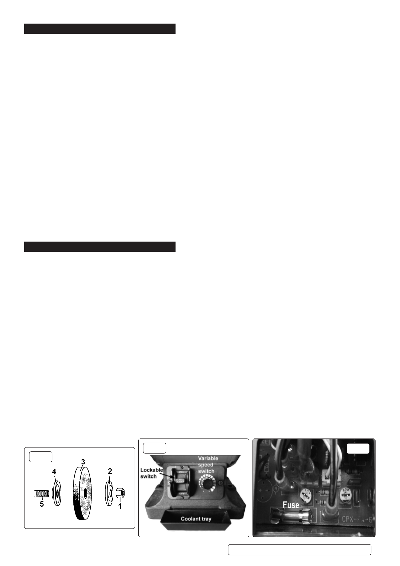
5.2.2. Remove the three screws and the corresponding nuts washers and lock washers from the side of the wheel cover and remove.
5.2.3. Hold grinding wheel firmly - protect your hands with a cloth, or wear gloves. Unscrew retaining nut (fig.3.1).
Note: The nut on the right side of the grinder has standard right-hand thread (undo anti-clockwise). The left side nut has a left-hand
thread and must be loosened by turning clockwise. It may be necessary to strike the wrench sharply in the loosening direction, with a
soft-faced hammer, to loosen the nut.
5.2.4. Remove grinding wheel washer (2), wheel (3), and washer (4) from main spindle (5). See fig.3.
5.2.5. Carefully inspect the new wheel before installing to ensure there are no fissures, chips, or cracks.
WARNING! DO NOT USE A DAMAGED WHEEL.
5.2.6. Install the new wheel by reversing steps above. Ensure washers (2 & 4) are installed correctly with the concave side against the wheel.
5.2.7. Hold wheel steady and secure locking nut 1 in fig .3. DO NOT over-tighten as this may crack the wheel.
5.2.8. Replace wheel cover, replace eye shield, re-adjust tool rest to not more than 2mm from wheel and tighten securely. Refer to section
‘Assembly’.
6. OPERATING
6.1. PRE-USE INSPECTION
WARNING! inspect the grinder before use. ensure the grinder is unplugged from the mains power before commencing the inspection.
6.1.1. Check the tool rests are securely xed and are not more than 2mm from the grinding wheels. See g.2.
6.1.2. Check that eye shields are in good condition, secure to grinder using supplied screws and that you can see through them clearly. See
g.1.
6.1.3. With the power switched off turn the grinding wheels by hand and check for any damage. Check they do not touch the tool rests and
are correctly aligned.
If any of the above checks fail, replace, repair, or adjust as necessary before starting the grinder.
6.2. WHEEL USE
6.2.1. The grinder is supplied with two aluminium oxide wheels, one course and one ne. Fine is preferred for hard materials and coarse for
soft materials.
6.2.2. If the surface of the wheel becomes “loaded” (coated with particles of the material being ground) it is probably the wrong grade for the
job. Important reminder: Only a person holding a grinding wheel certicate may install wheels. See Section 5.
6.3. USING THE GRINDER
WARNING! Before commencing work, ensure you read, understand and apply the Section 1 Safety Instructions.
6.3.1. Plug grinder into the mains power supply.
6.3.2. Adjust the eye shield to give maximum protection. Refer to Assembly section.
6.3.3. Switch on the grinder and bring the workpiece slowly into contact with the rotating wheel.
6.3.4. When the task is complete unplug the grinder from the mains power supply and clean the machine ready for next use.
6.3.5. Lockable Switch Refer to g.4.
6.3.6. The black centre section of the ON/OFF switch pulls out to prevent unauthorised use.
6.3.7. Overload Protection Fuse Refer to g.5. The fuse is located under the base plate. See 6.3.9 for more information.
WARNING! Ensure the grinder is unplugged from the mains power before changing the fuse.
6.3.8. Fuse rating is 5A.
6.3.9. An overload protection fuse is tted to the circuit board on the top of base cover assembly. Carefully turn the grinder on to its side.
Remove the four screws in each of the four suction feet on the base, remove the base cover and turn the board over. The fuse location
Is shown in g.5.
Original Language Version
© Jack Sealey Limited
BG150WVS BG200WVS Issue 4 (H,1,2,3,5) 22/11/23
g.4
g.5
g.3

7. MAINTENANCE
WARNING! Ensure the grinder is unplugged from the mains power supply before performing any maintenance or service.
7.1. As the grinding wheels wear, adjust the positions of the tool rests. Each rest must be set not more than 2mm from the grinding surface.
7.2. Regularly remove the grinding wheel covers and clean out any dust and dirt.
7.3. The machine motor and bearings are sealed units and require no regular maintenance. Should you require assistance, contact your
local service agent.
BG150WVS BG200WVS Issue 4 (H,1,2,3,5) 22/11/23
Sealey Group, Kempson Way, Suffolk Business Park, Bury St Edmunds, Suffolk. IP32 7AR
01284 757500 sales@sealey.co.uk www.sealey.co.uk
ZWEEE REGULATIONS
Dispose of this product at the end of its working life in compliance with the EU Directive on Waste Electrical and Electronic
Equipment (WEEE). When the product is no longer required, it must be disposed of in an environmentally protective way. Contact
your local solid waste authority for recycling information.
NOTE: It is our policy to continually improve products and as such we reserve the right to alter data, specications and component parts
without prior notice. Please note that other versions of this product are available. If you require documentation for alternative versions, please
email or call our technical team on technical@sealey.co.uk or 01284 757505.
IMPORTANT: No Liability is accepted for incorrect use of this product.
WARRANTY: Guarantee is 12 months from purchase date, proof of which is required for any claim.
ENVIRONMENT PROTECTION
Recycle unwanted materials instead of disposing of them as waste. All tools, accessories and packaging should be
sorted, taken to a recycling centre and disposed of in a manner which is compatible with the environment. When
the product becomes completely unserviceable and requires disposal, drain any uids (if applicable) into approved
containers and dispose of the product and uids according to local regulations.
Original Language Version
© Jack Sealey Limited
