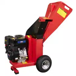
WOOD CHIPPER, 420CC, 15HP, 100MM
CAPACITY
MODEL NO: SWC420
Thank you for purchasing a Sealey product. Manufactured to a high standard, this product will, if used according to these
instructions, and properly maintained, give you years of trouble free performance.
IMPORTANT: PLEASE READ THESE INSTRUCTIONS CAREFULLY. NOTE THE SAFE OPERATIONAL REQUIREMENTS, WARNINGS & CAUTIONS. USE
THE PRODUCT CORRECTLY AND WITH CARE FOR THE PURPOSE FOR WHICH IT IS INTENDED. FAILURE TO DO SO MAY CAUSE DAMAGE AND/OR
PERSONAL INJURY AND WILL INVALIDATE THE WARRANTY. KEEP THESE INSTRUCTIONS SAFE FOR FUTURE USE.
1. SAFETY
WARNING! Ensure any Health & Safety, Government, or local authority regulations are adhered to when using this equipment.
9 IMPORTANT. Read Carefully Before Use. Keep For Future Reference.
9 Familiarise yourself with the application, limitations, and the potential hazards of the chipper.
9 Maintain the chipper in good condition (use an authorised service agent). Replace or repair damaged parts. Use genuine parts only.
Unauthorised parts may be dangerous and will invalidate the warranty.
9 This chipper is designed and manufactured for specific applications. DO NOT attempt to modify the unit or use it for any application for
which it is not designed. If you have any questions regarding the application of the unit please contact your local Sealey stockist.
WARNING! Chipper exhaust gases contain deadly carbon monoxide which must not be inhaled. Always allow sufficient ventilation.
WARNING! Petrol is highly flammable and petrol vapour is explosive. DO NOT permit smoking, naked flames, sparks or heat in the
vicinity while handling petrol. Avoid spilling petrol onto a hot engine. Comply with all laws regulating storage and handling of fuels.
WARNING! Risk of burns. DO NOT touch the exhaust system or the drive unit.
WARNING! NEVER refuel when the engine is running or when the engine is hot. Allow cool down time.
9 Operate the chipper only on level surfaces (maximum allowable tilt is 10º) and where it will not be exposed to excessive moisture, dirt
or corrosive vapours or be in the proximity of combustible material (flammable liquids, solids or gases).
9 Only operate the chipper in well ventilated areas / environments.
8 DO NOT tip or change the chipper’s position whilst it is operating.
9 Remove ill fitting clothing, ties, watches, rings and other loose jewellery and contain long hair. Wear appropriate protective clothing.
9 Keep non-essential persons and children away from the working area.
8 DO NOT use the chipper for any purpose other than that for which it is designed.
8 DO NOT operate the chipper if any parts are missing or damaged, as this may cause failure and/or personal injury.
8 DO NOT over-fill fuel tank. Always leave room for fuel to expand.
▲ DANGER! DO NOT tamper with the engine governed speed setting. Higher operating speeds are dangerous and increase the risk of
personal injury and/or equipment damage. Operating at excessively low speeds may result in shortened engine life. Over-speeding will
invalidate the warranty.
8 DO NOT operate the chipper when you are tired, or under the influence of alcohol, drugs or intoxicating medication.
8 DO NOT store chipper with fuel in tank where petrol vapours might reach an open flame or spark.
OPERATIONAL SAFETY
8 DO NOT allow children to operate this equipment.
8 DO NOT operate this equipment in the vicinity of bystanders. Keep bystanders away.
8 DO NOT run engine powered machines in an enclosed area since the exhaust from an engine contains carbon monoxide, which is
colourless, odourless, and tasteless. Carbon monoxide can be extremely dangerous in enclosed areas.
9 Wear ear protection and safety glasses at all times while operating the machine.
9 Avoid wearing clothing that is loose fitting or that has hanging cords or ties.
9 Only operate the machine in open space (e.g. not close to a wall or other fixed object) and on a firm, level surface.
8 DO NOT operate the machine on a paved or gravel surface where ejected material could cause injury.
9 Before starting the machine, check that all screws, nuts, bolts, and other fasteners are properly secured and that guards and screens
are in place. Replace damaged or unreadable labels.
9 Use extra care in handling fuels. They are flammable and the vapours are explosive. The following points should be observed:
: use only an approved container.
: never remove the fuel cap or add fuel while power source running.
Original Language Version
© Jack Sealey Limited
Refer to
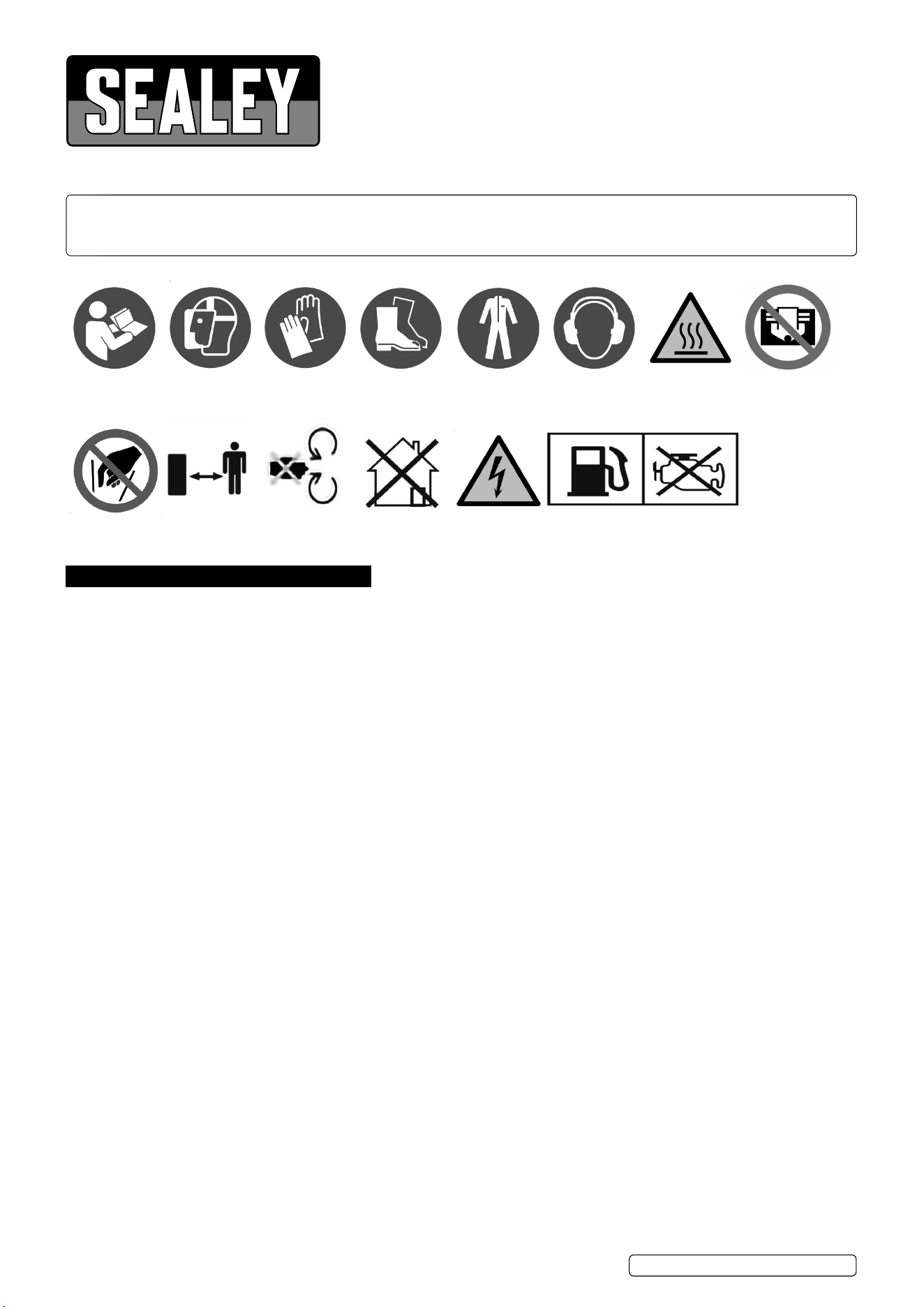
instructions
Hot surfaces Do not cover
Wear a Face
Shield
Wear protective
gloves
Wear ear
protection
Wear safety
footwear
Wear protective
clothing
No Reaching In
Keep
Bystanders
away.
Danger:
Rotating Blades
Ensure Good
Ventilation
SWC420 Issue 1 07/11/23
Electric Shock
Hazard
Switch O engine Before
Refuelling
: Allow engine and exhaust components to cool before refuelling.
: DO NOT smoke.
: never refuel the machine indoors.
: never store the machine or fuel container inside where there is an open flame, such as a water heater.
8 If fuel is spilt, DO NOT attempt to start the power source, but move the machine away from the area of spillage before starting.
9 Always replace and securely tighten the fuel cap after refuelling.
9 If the fuel tank is drained, this should be done outdoors.
9 Before starting the machine, look into the feeding chamber to make certain that it is empty.
9 Keep your face and body away from the feed intake opening.
8 DO NOT allow hands or any other part of the body or clothing inside the feeding chamber, discharge chute, or near any moving part.
9 Keep proper balance and footing at all times. DO NOT overreach. Never stand at a higher level than the base of the machine when
feeding material into it.
9 Always stand clear of the discharge zone when operating this machine.
9 When feeding material into the machine be extremely careful that pieces of metal, rocks, bottles, cans or other foreign objects are not
included.
9 If the cutting mechanism strikes any foreign objects or if the machine should start making any unusual noise or vibration, shut off the
power source and allow the machine to stop. Disconnect the spark plug wire from the spark plug (electric unit disconnect from supply)
and take the following steps:
: inspect for damage.
: check for and tighten any loose parts .
: have any damaged parts replaced or repaired with parts having equivalent specifications.
8 DO NOT allow processed material to build up in the discharge zone. this may prevent proper discharge and can result in kickback of
material through the feed intake opening.
9 If the machine becomes clogged at the inlet opening or discharge chute shut off the power source and disconnect the spark plug wire
or remove the ignition key before clearing debris in the inlet opening or discharge chute. Keep the power source clear of debris and other
accumulations to prevent damage to the unit or possible fire. Remember that operating the starting mechanism on engine
powered machines will still cause the cutting blades to move.
9 Keep all guards and deflectors in place and in good working condition.
8 DO NOT tamper with the power source governor settings; the governor controls the safe maximum operating speed and protects the
power source and all moving parts from damage caused by over-speed. Seek authorised service if a problem exists.
8 DO NOT transport this machine while the power source is running.
9 Shut off the power source and disconnect the spark plug lead (electric unit disconnect from supply) whenever you leave the work area.
8 DO NOT tilt the machine while the power source is running.
9 Position the machine such that it is not necessary to work downwind of the exhaust.
2. INTRODUCTION
Safe and easy way to chip wood, powered by a 420cc engine with a speed of 3600rpm. Chips wood almost instantly upon contact, keeping
labour and work time to a minimum. Features self-feeding chipping hopper and adjustable height of the discharge port. Supplied with wheels
for easy manoeuvrability. Chipping capacity: 100mm. Fuel type: Unleaded Petrol. Motor Power: 15hp/3600rpm. Overall Size (W x D x H): 842 x
1285 x 1245mm.
3. SPECIFICATION
Model no.: ................................................................SWC420
Blade Speed: ...........................................................2400rpm
Drive Type: ............................................................Belt Driven
Engine Capacity: .......................................................... 420cc
Engine Type: ..................................Overhead Valve 4-Stroke
Fuel Tank: .......................................................................6.5L
Fuel: .............................. Unleaded 95 RON - E10 compatible
Max. Engine Speed: .................................................3500rpm
Maximum Power: ........................................15hp @ 3600rpm
Noise Rating: ................................................. 114/94.3 dB(A)
Oil Volume: .....................................................................1.1L
Starting System: ...........................................................Recoil
Noise Test Code: ...................................... EN ISO 3744:1995
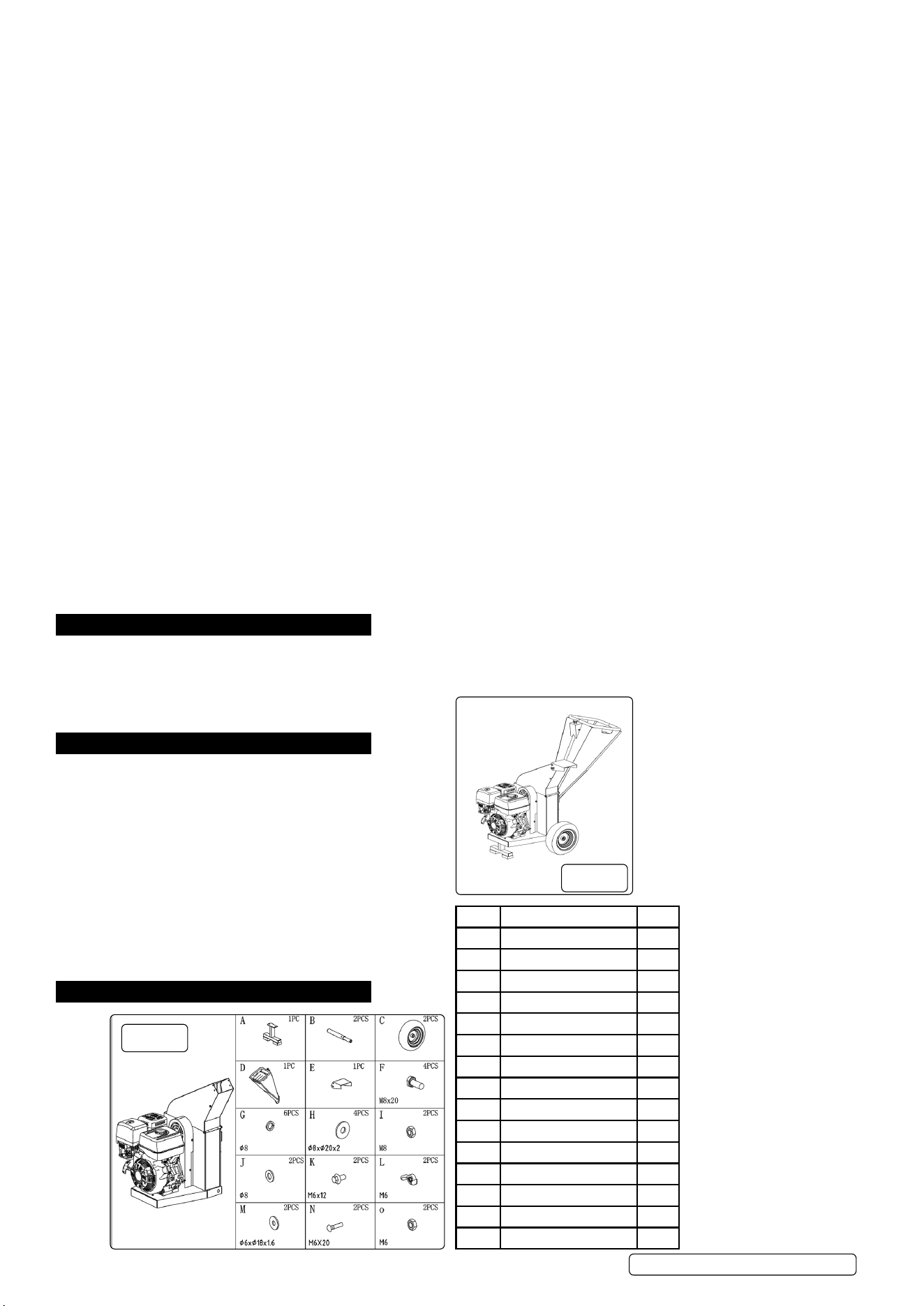
4. ASSEMBLY
4.1. COMPONENT PARTS
ITEM Description Qty.
A Support 1
B Axle 2
C Tyres 2
D Feed Hopper 1
E Discharge Port 1
F Bolt M8x20 4
G Ø8 Spring Washer 6
H Ø8x20x2 Washer 4
I Hex. nut M8 2
J Ø8 Plain Washer 2
K Bolt M6 x 12 2
L M6 Wing Nut 2
M Ø6xØ18x1.6 Washer 2
N Bolt M6x20 2
O Hex Nut M6 2
g.1
g.2
Original Language Version
© Jack Sealey Limited
SWC420 Issue 1 07/11/23
Original Language Version
© Jack Sealey Limited
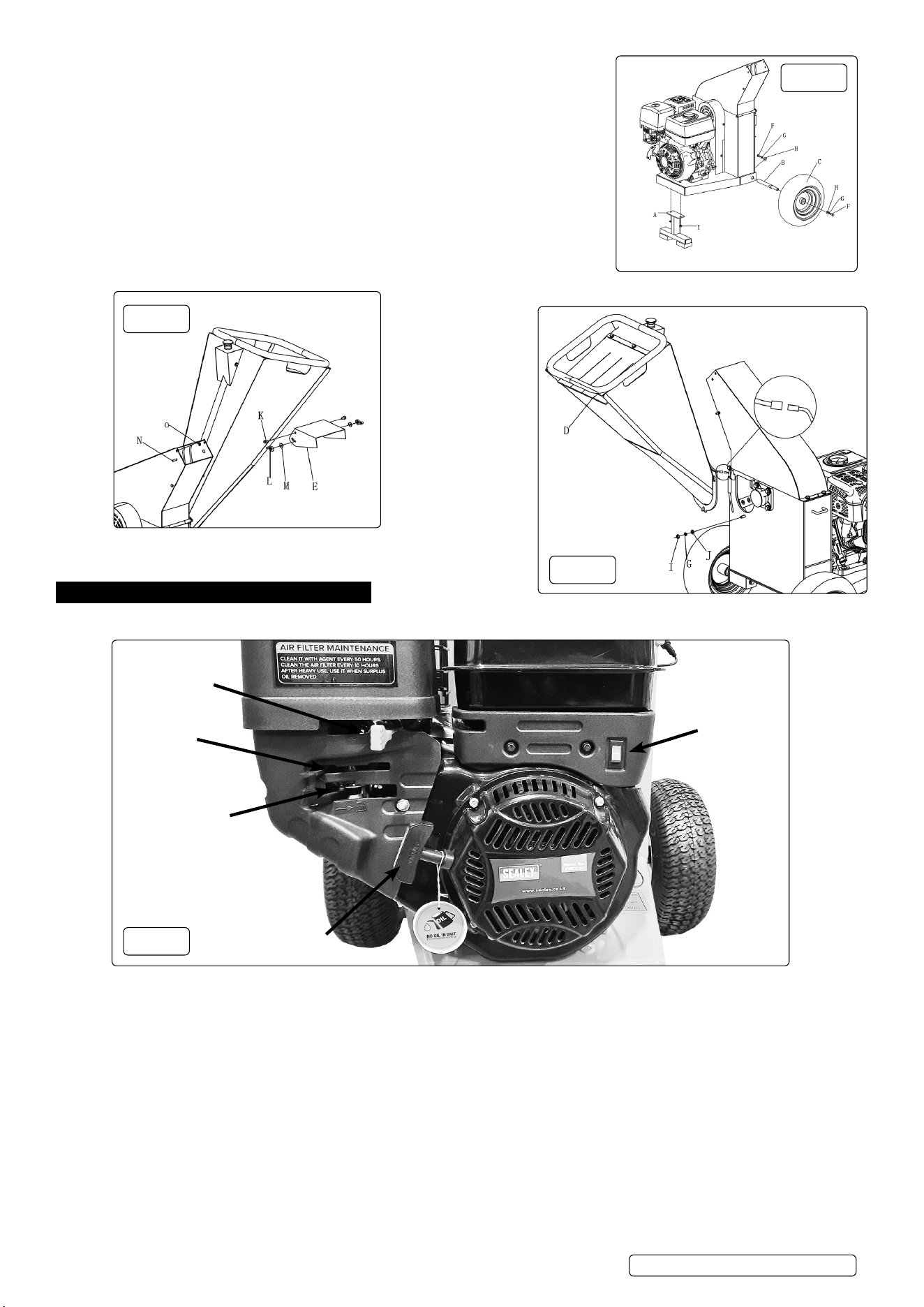
4.2. SUPPORTLEGANDWHEELASSY(g.3)
4.2.1. Attach the Support (A) to the main body by using Nut M8 (I).
4.2.2. Install the wheels on both sides to the main body by using Tyres (C) , Wheel Axle (B) ,
Bolt M8x20 (F), Ø8 Spring Washer (G) and Ø8x20x2 Flat Washer (H).
4.3. FEED HOPPER ASSY(g.4,g.5)
4.3.1. Open the main body cover by loosening the screw.
4.3.2. Install the Feed Hopper(D) to the main body by using Ø8 Flat Washer(J) , Ø8 Spring
Washer (G) and Nut M8 (I).
4.3.3. Close the main body cover by retightening the screw
4.3.4. Connect the wire connector
4.4. DISCHARGEPORT(g.4)
4.4.1. Install the Discharge Port (E) to the main body cover by using Bolt M6x12 (K),
Nut M6 (O), Bolt M6x20 (N), Ø6xØ18x1.6 Flat Washer (M) and Wing Nuts (L).
5. OPERATION
5.1. CONTROLS(g.6)
Fuel Valve Control
Choke Lever
Recoil Starter
ON / OFF
Switch
Throttle Control
5.1.1. IMPORTANT: Ensure engine has correct oil level prior to each use.
5.2. FUEL VALVE CONTROL (g.6) The fuel valve opens and closes the fuel line between the fuel tank and the carburettor. The fuel
valve lever must be in the ON position for the engine to run. When the engine is not in use, leave the fuel valve lever in the
OFF position to prevent carburettor ooding and to reduce the possibility of fuel leakage.
5.3. THROTTLE CONTROL LEVER (g.6)
5.3.1. The throttle lever controls engine speed. Moving the throttle lever makes the engine run faster or slower.
5.4. ENGINE ON/OFF SWITCH (g.6)
5.4.1. The engine switch enables and disables the ignition system. The engine switch must be in the ON position for the engine to run.
Turning the engine switch to the OFF position stops the engine.
5.5. CHOKE LEVER (g.6)
5.5.1. The choke lever opens and closes the choke valve in the carburettor. The closed position enriches the fuel mixture for starting a cold
engine.
5.5.2. The open position provides the correct fuel mixture for operation after starting, and for restarting a warm engine.
g.4
g.5
g.3
g.6
SWC420 Issue 1 07/11/23
5.5.3. RECOIL STARTER GRIP (g.6)
5.5.4. Pulling the starter grip operates the recoil starter to crank the engine.
5.6. FEEDHOPPER(g.5)
5.6.1. The opening into which all materials to be chipped should be fed.
5.7. DISCHARGEPORT(g.4)
5.7.1. Chipped materials are discharged through this opening. Deector should be attached to the chute.
5.8. DEFLECTORLEVER(g.4)
5.8.1. Loosen it in the anti-clockwise direction to adjust discharge angle. Tighten it in the clockwise direction.
5.9. EMERGENCYSTOP(g.7)
5.9.1. Rotate the Emergency Stop button to engage this feature. The button will rise up.
5.9.2. If an emergency stop is required whilst running, depress the switch. NOTE: the chipper will run on for a few seconds before stopping.
5.10. ON PROCEDURE
5.10.1. Check oil and fuel (g.7). NOTE: THE ENGINE IS NOT SUPPLIED WITH OIL.
5.10.2. If from cold, set Choke on (g.6). If not ensure choke is set o.
5.10.3. Turn fuel supply on (g.6).
5.10.4. Set throttle lever to full on (rabbit symbol g.6).
5.10.5. Prepare Emergency Dead Stop switch (g.7).
5.10.6. Switch ignition circuit on (g.6)
5.10.7. Apply Recoil Start (g.6)
5.10.8. Once started and warmed, set choke o (g.6)
5.10.9. Adjust throttle lever to reqd value (g.6)
5.11. OFF PROCEDURE
5.11.1. Throttle o (g.6)
5.11.2. Fuel o (g.6)
5.11.3. Switch o (g.6)
5.12. OPERATING PROCEDURE
5.12.1. Place the unit on a level surface that will support its weight.
5.12.2. Inspect unit before each use or at the start of each shift. The disc hood g.7) should be closed and latched. Check the infeed chute for
foreign objects. Make sure bolts and pins are tight. Inspect the knives for wear or damage. Running the chipper with worn or damaged
knives can cause the feed to clog and eventually kick debris back through the feed hopper chute.
5.12.3. Check the guards. Make sure they’re not missing.
5.12.4. Check oil level. NOTE: The unit has a low oil level sensor which will stop the engine when low thus preventing internal damage.
5.12.5. Point the discharge chute away from people and trac.
5.12.6. Check tree debris before feeding it into the chipper to make sure it doesn’t contain foreign objects. Never throw other materials into the
machine.
Original Language Version
© Jack Sealey Limited
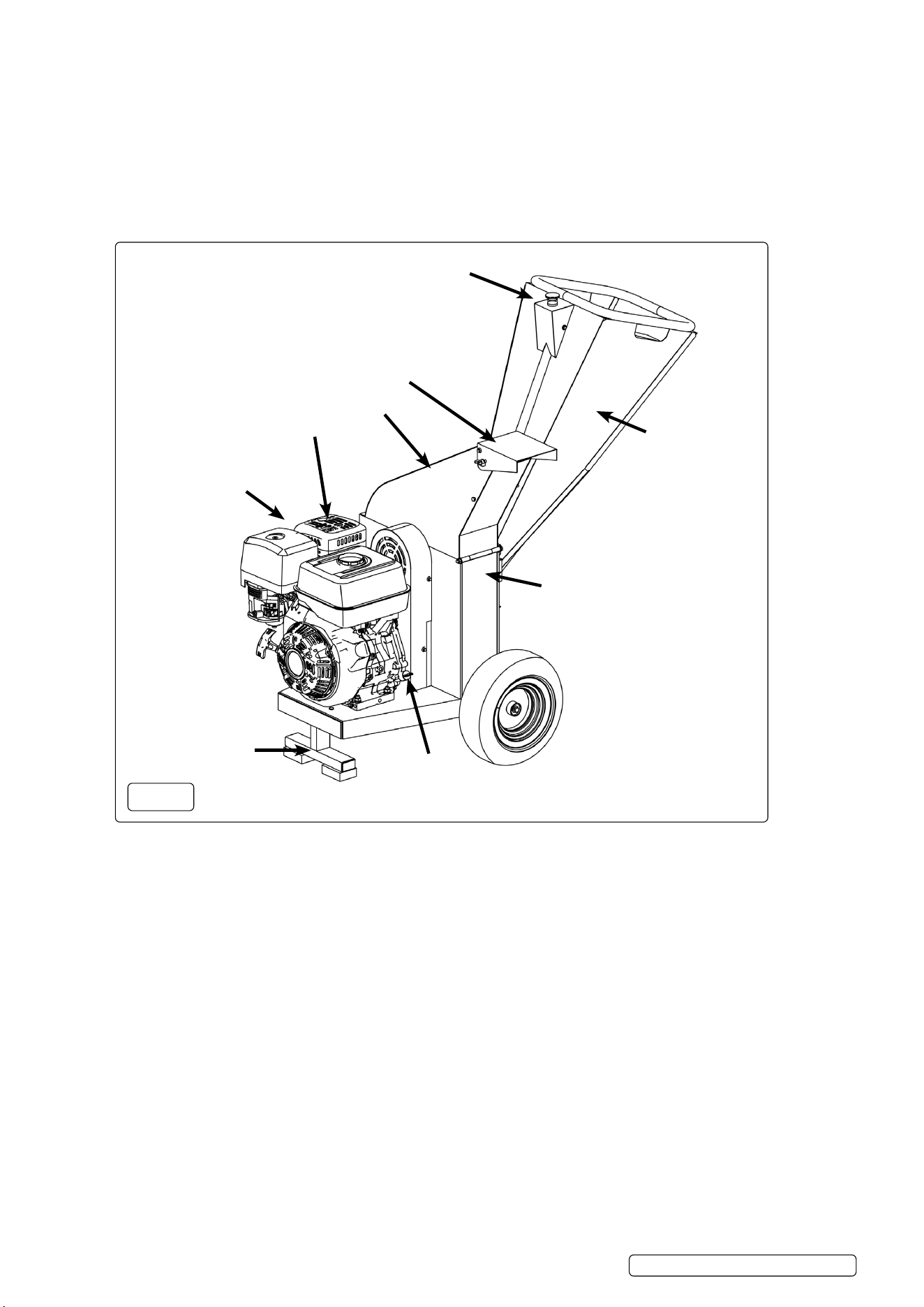
Emergency Stop
Support Leg
Oil Dip Stick
(both sides)
Air Filter Housing
Main Body
Discharge Port
Feed Hopper
g.7
Spark Plug on
Far-Side
SWC420 Issue 1 07/11/23
Hood

5.12.7. Limit the size of the pieces you insert. DO NOT feed the machine with material that is larger than it is rated for.
5.12.8. Stay free and clear as you feed. Stand to the side of the infeed chute, pushing materials in with a wooden push tool or long branch and
feeding branches in butt-end rst and placing shorter branches on top of longer ones.
5.12.9. Before starting the machine, look into the feeding chamber to make certain that it is empty.
5.12.10. Keep your face and body away from the feed intake opening.
8 DO NOT allow hands or any other part of the body or clothing inside the feeding chamber, discharge chute, or near any moving part.
Keep proper balance and footing at all times.
8 DO NOT overreach. Never stand at a higher level than the base of the machine when feeding material into it. Always stand clear of the
discharge zone when operating this machine
5.12.11. When feeding material into the machine be extremely careful that pieces of metal, rocks, bottles, cans or other foreign objects are not
included.
5.12.12. If the cutting mechanism strikes any foreign objects or if the machine should start making any unusual noise or vibration, shut o the
power source and allow the machine to stop. Disconnect the spark plug wire from the spark plug (electric unit disconnect from supply)
and inspect for damage check for any loose parts and tighten.
5.12.13. Have any damaged parts replaced or repaired with parts having equivalent specications.
8 DO NOT allow processed material to build up in the discharge zone. this may prevent proper discharge and can result in kickback of
material through the feed intake opening.
5.12.14. If the machine becomes clogged at the inlet opening or discharge chute shut-o the power source and disconnect the spark plug wire
or remove the ignition key before clearing debris in the inlet opening or discharge chute.
5.12.15. Keep the power source clear of debris and other accumulations to prevent damage to the power source or possible re. Remember
that operating the starting mechanism on engine powered machines will still cause the cutting means to move.
5.12.16. Keep all guards and deectors in place and in good working condition.
8 DO NOT tamper with the power source governor settings. the governor controls the safe maximum operating speed and protects the
power source and all moving parts from damage caused by over-speed. Seek authorised service if a problem exist.
8 DO NOT transport this machine while the power source is running.
5.12.17. Shut o the power source and disconnect the spark plug lead (electric unit disconnect from supply) whenever you leave the work area.
8 DO NOT tilt the machine while it is running.
6. MAINTENANCE
6.1. Have your machine serviced by qualied repair personnel using only identical replacement parts. This will ensure the safety of the
machine is maintained.
WARNING When the machine is stopped for servicing, inspection, or storage, or to change an accessory, shut o the power source
and disconnect the spark plug wire from the spark plug.
6.2. Make sure that all moving parts have come to a complete stop.
6.3. Allow the machine to cool before making any inspections, adjustments, etc.
6.4. Store the machine where fuel vapour will not reach an open ame or spark. For extended storage periods, run the unit dry of fuel.
Always allow the machine to cool before storing.
6.5. When servicing the cutting means be aware that the cutting means can still be moved by a manual starting mechanism.
WARNING: Switch o the motor and pull the spark plug boot from the spark plug before doing any cleaning and maintenance work on
the equipment.
IMPORTANT: Switch o the machine immediately and contact your Sealey stockist:
in the event of unusual vibrations or noise.
if the engine appears to be overloaded or misres.
6.6. CLEANING
6.6.1. Keep all safety devices, air vents and the motor housing free of dirt and dust as far as possible.
6.6.2. Wipe the equipment with a clean cloth or blow it with compressed air at low pressure.
6.6.3. We recommend that you clean the device immediately each time you have nished using it. Clean the equipment regularly with a moist
cloth and some soft soap. DO NOT use cleaning agents or solvents. These could attack the plastic parts of the equipment. Ensure that
no water can seep into the device.
6.7. AIR FILTER SEE FIG. 7
6.7.1. Clean the air lter at regular intervals, and replace it if necessary.
6.7.2. Open and remove the air lter cover, see g. 7.
6.7.3. Remove the lter elements, see g.7. DO NOT use abrasive cleaning agents or petrol to clean the elements. Clean the elements by
tapping them on a at surface. In cases of stubborn dirt rst clean with soapy water, then rinse with clear water and air dry.
6.7.4. Assemble in reverse order.
6.8. SPARK PLUG see g.7 Check the spark plug for dirt and grime after 20 hours of operation and if necessary clean with a copper wire
brush. Thereafter service the spark plug after every 50 hours of operation.
6.8.1. Pull o the spark plug boot with a twist.
6.8.2. Remove the spark plug with the supplied spark plug wrench.
6.8.3. Assemble in reverse order.
6.9. GREASING BEARINGS
6.9.1. All accessible bearings have grease nipples tted. Lubricate with suitable grease as required.
6.10. CHANGING THE OIL AND CHECKING THE OIL LEVEL see g.7.
6.10.1. Check oil level before using the machine. see g.7.
6.10.2. Only use motor oil (15W40).
6.10.3. NOTE: The unit has a low oil level sensor which will stop the engine when low thus preventing internal damage.
Original Language Version
© Jack Sealey Limited
SWC420 Issue 1 07/11/23

7. TROUBLESHOOTING
Problem Cause Remedy
Engine fails to start Spark plug wire disconnected Attach spark plug wire securely to spark
plug
Out of fuel or stale fuel Fill with clean, fresh gasoline
Fuel valve not in ON position Fuel valve must be in ON position
Choke lever not in CLOSE position Choke level must be in CLOSE position for
a cold start
Blocked fuel line Clean the fuel line
Fouled spark plug Clean, adjust gap, or replace
Engine ooding Wait a few minutes to restart, but do not
prime
Engine runs
Erratically
Spark plug wire loose
Unit running with Choke lever in CLOSE position
Blocked fuel line or stale fuel
Vent plugged
Water or dirt in fuel system
Dirty air cleaner
Improper carburettor adjustment
Connect and tighten spark plug wire
Move choke lever to OPEN position
Clean fuel line. Fill tank with clean, fresh
gasoline
Clear vent
Drain fuel tank. Rell with fresh fuel
Clean or replace air cleaner
Refer to Engine Manual
Engine overheats Engine oil level low
Dirty air cleaner
Air ow restricted
Carburettor not adjusted properly
Fill crankcase with correct oil
Clean air cleaner
Remove housing and clean
Refer to Engine Manual
Chipping action too slow,
or cutting disk stalls, or
no material is discharged
The engine speed is too slow causing belt to slip
Drive Belt loose or damaged
Knives dull or damaged
Cutting disk jammed by debris from the feed hopper and
discharge chute
Discharge chute clogged
Run the engine at full throttle
Tighten or replace drive belt
Sharpen or replace knives
Remove any built-up debris and turn cutting
disk with a wooden stick to be sure it turns
freely
Clean out debris
The belt frays or
Rolls over the pulley
The rotor drive pulley groove may be nicked
The drive belts may be stretched
The pulleys may be misaligned
Check the drive belts for wear and hard
spots. File o any nicks on the pulley
Replace the drive belts
Adjust the pulleys
Vibrate and move about
excessively with unusual
noise when working
Knives dull or damaged Sharpen or replace knives
Loosen the knives mounting screws, reset
the knives and tighten the screws
Adjust the gap
Allow unit to clear itself before adding more
material to the hopper
Knives is not properly seated on the cutting disk
The gap between the knives and wear plate is too large
Rotor overloaded with material
Chipper Knives
Are hitting the
Wear plate
The gap between the knives and wear plate is set
incorrectly.
Adjust the gap.
Sealey Group, Kempson Way, Suffolk Business Park, Bury St Edmunds, Suffolk. IP32 7AR
01284 757500 sales@sealey.co.uk www.sealey.co.uk
ENVIRONMENT PROTECTION
Recycle unwanted materials instead of disposing of them as waste. All tools, accessories and packaging should be sorted, taken to
a recycling centre and disposed of in a manner which is compatible with the environment. When the product becomes completely
unserviceable and requires disposal, drain any fluids (if applicable) into approved containers and dispose of the product and fluids
according to local regulations.
Note: It is our policy to continually improve products and as such we reserve the right to alter data, specifications and component parts
without prior notice.
Important: No Liability is accepted for incorrect use of this product.
Warranty: Guarantee is 12 months from purchase date, proof of which is required for any claim.
REGISTER YOUR
PURCHASE HERE
Original Language Version
© Jack Sealey Limited
SWC420 Issue 1 07/11/23