Loading ...
Loading ...
Loading ...
9
ASSEMBLY
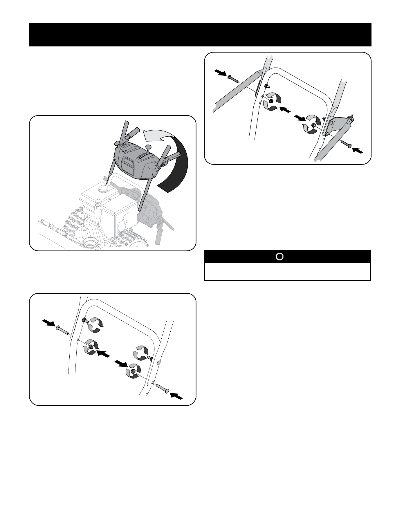
4. Place shift lever in Forward-6 position or fastest forward speed (if equipped).
5. Pull up and back on upper handle as shown in Figure 5. As you are raising the
handle upward, make sure that both ends of the center cable are positioned
properly in the brackets. Align upper handle with the lower handle.
NOTE: On select units with steel rod speed selectors, you may need to lower shift
rod to the side slightly to maneuver handle panel over it when pivoting handle
upward.
Figure 5
6. Attach the two carriage screws and lock nuts removed in Step 2. Finish
securing the handle by tightening the top two lock nuts loosened in Step 2.
See Figure 6 or Figure 7 for units with side supports.
Figure 6
Figure 7
7. Remove and discard any rubber bands, if present. They are for packaging
purposes only.
8. On units equipped with cable guides on top of the engine, check that all
cables are properly routed through the cable guide. Then pull the cables
towards the chute and pull the cable tie on the engine snug on the cables to
secure in place.
NOTE: For smoothest operation, cables should all be to the left of the chute
directional control rod.
STOP
Refer to Figure 1 to identify your applicable chute style and continue to
Chute Assembly Options (page 9).
Chute Assembly Options
Refer to Figure 1 and proceed to your applicable Chute Control Style on pages 10-15.
Loading ...
Loading ...
Loading ...