Loading ...
Loading ...
Loading ...
14
ASSEMBLY
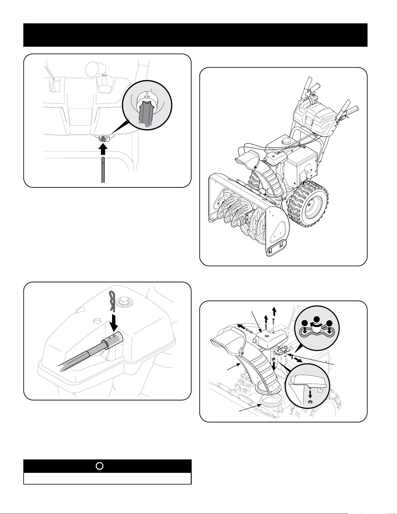
Figure 24
NOTE: Chute control rod will fit snug into pinion gear. Support rear of dash
panel with one hand while inserting rod with your other hand to ensure rod
is inserted all the way into pinion gear.
NOTE: The hole in the chute directional control rod is a reference for aligning
rod with indicator arrow on pinion gear, and will be visible after rod has been
inserted.
7. Push chute control rod toward control panel until hole in rod lines up with
hole in chute control input closest to chute control head and insert hairpin
clip (a)removed in Step 1. See Figure 25.
Figure 25
NOTE: Second hole is used to achieve further engagement of chute control
rod into pinion gear if required. Refer to Service section for Chute Control
Rod adjustments.
8. Finish securing chute control head to chute support bracket with wing nut,
clevis pin, and bow-tie cotter pin (e) removed in Step 1.
STOP
Continue to Set-Up (page 16).
Electric Chute Control
Figure 26
1. Remove cotter pin, wing nut, and hex screw from chute control head and
clevis pin and bow-tie cotter pin from chute support bracket. See Figure 27.
Chute Control Head
Chute
1
1
2
Chute
Support
Bracket
Chute Base
Figure 27
NOTE: For smoothest operation, the cables should all be to the left of the chute
control rod.
Loading ...
Loading ...
Loading ...