
Gigabit PoE Switch Web
User Manual

Legal Informaon
©2020 Hangzhou Hikvision Digital Technology Co., Ltd. All rights reserved.
About this Manual
The Manual includes instrucons for using and managing the Product. Pictures, charts, images and
all other informaon hereinaer are for descripon and explanaon only. The informaon
contained in the Manual is subject to change, without noce, due to rmware updates or other
reasons. Please
nd the latest version of this Manual at the Hikvision website ( hps://
www.hikvision.com/ ).
Please use this Manual with the guidance and assistance of professionals trained in
supporng the
Product.
Trademarks
and other Hikvision's trademarks and logos are the properes of
Hikvision in various
jurisdicons.
Other trademarks and logos menoned are the properes of their respecve owners.
Disclaimer
TO THE MAXIMUM EXTENT PERMITTED BY APPLICABLE LAW, THIS MANUAL AND THE PRODUCT
DESCRIBED, WITH ITS HARDWARE, SOFTWARE AND FIRMWARE, ARE PROVIDED “AS IS” AND “WITH
ALL FAULTS AND ERRORS”. HIKVISION MAKES NO WARRANTIES, EXPRESS OR IMPLIED, INCLUDING
WITHOUT LIMITATION, MERCHANTABILITY, SATISFACTORY QUALITY, OR FITNESS FOR A PARTICULAR
PURPOSE. THE USE OF THE PRODUCT BY YOU IS AT YOUR OWN RISK. IN NO EVENT WILL HIKVISION
BE LIABLE TO YOU FOR ANY SPECIAL, CONSEQUENTIAL, INCIDENTAL, OR INDIRECT DAMAGES,
INCLUDING, AMONG OTHERS, DAMAGES FOR LOSS OF BUSINESS PROFITS, BUSINESS
INTERRUPTION, OR LOSS OF DATA, CORRUPTION OF SYSTEMS, OR LOSS OF DOCUMENTATION,
WHETHER BASED ON BREACH OF CONTRACT, TORT (INCLUDING NEGLIGENCE), PRODUCT LIABILITY,
OR OTHERWISE, IN CONNECTION WITH THE USE OF THE PRODUCT, EVEN IF HIKVISION HAS BEEN
ADVISED OF THE POSSIBILITY OF SUCH DAMAGES OR LOSS.
YOU ACKNOWLEDGE THAT THE NATURE OF INTERNET PROVIDES FOR INHERENT SECURITY RISKS,
AND HIKVISION SHALL NOT TAKE ANY RESPONSIBILITIES FOR ABNORMAL OPERATION, PRIVACY
LEAKAGE OR OTHER DAMAGES RESULTING FROM CYBER-ATTACK, HACKER ATTACK, VIRUS
INSPECTION, OR OTHER INTERNET SECURITY RISKS; HOWEVER, HIKVISION WILL PROVIDE TIMELY
TECHNICAL SUPPORT IF REQUIRED.
YOU AGREE TO USE THIS PRODUCT IN COMPLIANCE WITH ALL APPLICABLE LAWS, AND YOU ARE
SOLELY RESPONSIBLE FOR ENSURING THAT YOUR USE CONFORMS TO THE APPLICABLE LAW.
ESPECIALLY, YOU ARE RESPONSIBLE, FOR USING THIS PRODUCT IN A MANNER THAT DOES NOT
INFRINGE ON THE RIGHTS OF THIRD PARTIES, INCLUDING WITHOUT LIMITATION, RIGHTS OF
PUBLICITY, INTELLECTUAL PROPERTY RIGHTS, OR DATA PROTECTION AND OTHER PRIVACY RIGHTS.
YOU SHALL NOT USE THIS PRODUCT FOR ANY PROHIBITED END-USES, INCLUDING THE
DEVELOPMENT OR PRODUCTION OF WEAPONS OF MASS DESTRUCTION, THE DEVELOPMENT OR
Gigabit PoE Switch Web User Manual
i

PRODUCTION OF CHEMICAL OR BIOLOGICAL WEAPONS, ANY ACTIVITIES IN THE CONTEXT RELATED
TO ANY NUCLEAR EXPLOSIVE OR UNSAFE NUCLEAR FUEL-CYCLE, OR IN SUPPORT OF HUMAN
RIGHTS ABUSES.
IN THE EVENT OF ANY CONFLICTS BETWEEN THIS MANUAL AND THE APPLICABLE LAW, THE LATER
PREVAILS.
Gigabit PoE Switch Web User Manual
ii

Regulatory Informaon
FCC Informaon
Please take aenon that changes or modicaon not expressly approved by the party responsible
for compliance could void the user's authority to operate the equipment.
FCC compliance: This equipment has been tested and found to comply with the limits for a Class A
digital device, pursuant to part 15 of the FCC Rules. These limits are designed to provide
reasonable
protecon against harmful interference when the equipment is operated in a
commercial environment. This equipment generates, uses, and can radiate radio frequency energy
and, if not installed and used in accordance with the
instrucon manual, may cause harmful
interference to radio communicaons. Operaon of this equipment in a residenal area is likely to
cause harmful interference in which case the user will be required to correct the interference at his
own expense.
FCC Condions
This device complies with part 15 of the FCC Rules. Operaon is subject to the following two
condions:
1. This device may not cause harmful interference.
2. This device must accept any interference received, including interference that may cause
undesired
operaon.
EU Conformity Statement
This product and - if applicable - the supplied accessories too are marked with
"CE" and comply therefore with the applicable harmonized European
standards listed under the EMC Direcve 2014/30/EU, the RoHS Direcve
2011/65/EU.
2012/19/EU (WEEE direcve): Products marked with this symbol cannot be
disposed of as unsorted municipal waste in the European Union. For proper
recycling, return this product to your local supplier upon the purchase of
equivalent new equipment, or dispose of it at designated
collecon points.
For more
informaon see: hp://www.recyclethis.info .
2006/66/EC (baery direcve): This product contains a baery that cannot be
disposed of as unsorted municipal waste in the European Union. See the
product documentaon for specic baery informaon. The baery is
marked with this symbol, which may include
leering to indicate cadmium
(Cd), lead (Pb), or mercury (Hg). For proper recycling, return the
baery to
your supplier or to a designated
collecon point. For more informaon see:
hp://www.recyclethis.info .
Gigabit PoE Switch Web User Manual
iii

Industry Canada ICES-003 Compliance
This device meets the CAN ICES-3 (A)/NMB-3(A) standards requirements.
Gigabit PoE Switch Web User Manual
iv
Preface
Applicable Models
This manual is applicable to DS-3E15XXP series switch and guides you to complete the
conguraon and operaon of the switch.
About the Default
• Default administrator account: admin.
• Default IP address: 192.168.1.64.
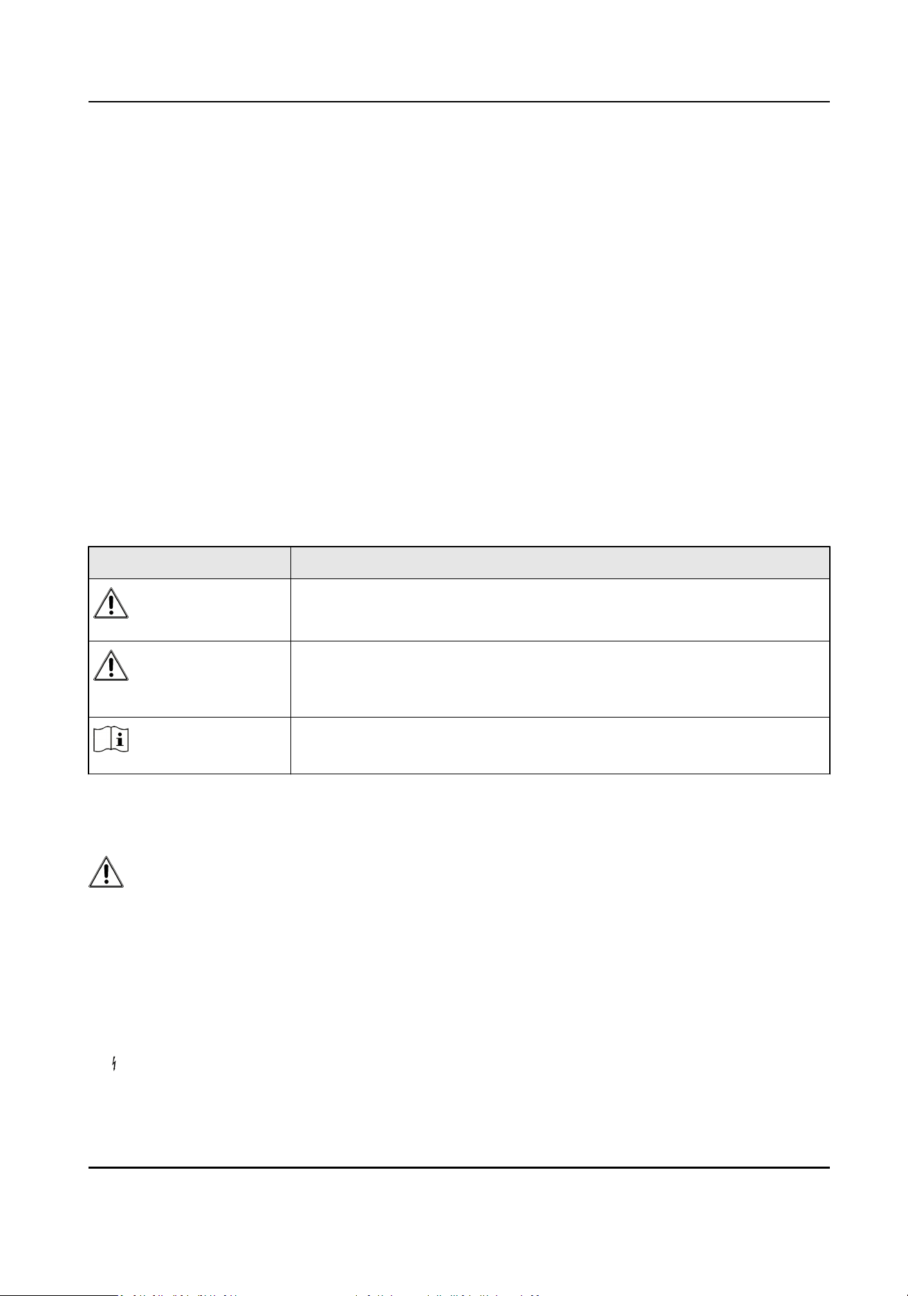
Symbol
Convenons
The symbols that may be found in this document are dened as follows.
Symbol Descripon
Danger
Indicates a hazardous situaon which, if not avoided, will or could
result in death or serious injury.
Cauon
Indicates a potenally hazardous situaon which, if not avoided, could
result in equipment damage, data loss, performance degradaon, or
unexpected results.
Note
Provides addional informaon to emphasize or supplement
important points of the main text.
Safety Instrucon
Danger
• This is a class A product and may cause radio interference in which case the user may be
required to take adequate measures.
• In the use of the product, you must be in strict compliance with the electrical safety regulaons
of the naon and region.
• The socket-outlet shall be installed near the device and shall be easily accessible.
• The device must be connected to an earthed mains socket-outlet.
• Install the device according to the
instrucons in this manual.
•
indicates hazardous live and the external wiring connected to the terminals requires
installaon by an instructed person.
Gigabit PoE Switch Web User Manual
v

• Keep body parts away from fan blades. Disconnect the power source during servicing.
• Never place the device in an unstable
locaon. The device may fall, causing serious personal
injury or death.
• This device is not suitable for use in
locaons where children are likely to be present.
• CAUTION: Risk of explosion if the
baery is replaced by an incorrect type.
• Improper replacement of the
baery with an incorrect type may defeat a safeguard (for
example, in the case of some lithium baery types).
• Do not dispose of the
baery into re or a hot oven, or mechanically crush or cut the baery,
which may result in an explosion.
• Do not leave the baery in an extremely high temperature surrounding environment, which may
result in an explosion or the leakage of ammable liquid or gas.
• Do not subject the
baery to extremely low air pressure, which may result in an explosion or the
leakage of ammable liquid or gas. Dispose of used baeries according to the instrucons.
Cauon
• CAUTION: Double pole/Neutral fusing.
Aer operaon of the fuse, parts of the device that
remain energized might represent a hazard during servicing.
• The device has been designed, when required, modied for connecon to an IT power
distribuon system.
• This device is suitable for
mounng on concrete or other non-combusble surface only.
• The
venlaon should not be impeded by covering the venlaon openings with items, such as
newspapers, table-cloths, curtains, etc. The openings shall never be blocked by placing the
device on a bed, sofa, rug or other similar surface.
• No naked
ame sources, such as lighted candles, should be placed on the device.
• The device shall not be exposed to dripping or splashing and that no objects lled with liquids,
such as vases, shall be placed on the device.
• Burned
ngers when handling the cover area of the device. Wait one-half hour aer switching
o before handling the parts.
• CLASS 1 LASER PRODUCT
Gigabit PoE Switch Web User Manual
vi

Contents
Chapter 1 Introducon ............................................................................................................... 1
Chapter 2 Acvaon and Login ................................................................................................... 2
Chapter 3 Device Management ................................................................................................... 4
Chapter 4 Switch Conguraon .................................................................................................. 7
4.1 Port Conguraon .................................................................................................................. 7
4.1.1 Aribute Conguraon ................................................................................................. 7
4.1.2 Port Mirroring ............................................................................................................... 8
4.1.3 Port Rate-Liming ......................................................................................................... 9
4.1.4 Storm Control
Conguraon ....................................................................................... 10
4.1.5 Long-Range Mode Conguraon ................................................................................ 11
4.2 Link Aggregaon Conguraon ............................................................................................ 12
4.3 VLAN
Conguraon .............................................................................................................. 14
4.3.1 Add a VLAN ................................................................................................................. 14
4.3.2 Congure a Port .......................................................................................................... 15
4.4 QoS
Conguraon ................................................................................................................ 16
4.5 SNMP Conguraon ............................................................................................................. 18
4.5.1 SNMP Proxy Sengs ................................................................................................... 19
4.5.2 SNMP Trap
Sengs ..................................................................................................... 19
4.6 STP Conguraon ................................................................................................................. 20
4.6.1 Global Conguraon ................................................................................................... 20
4.6.2 STP Port
Conguraon ................................................................................................ 22
4.6.3 STP Status View ........................................................................................................... 24
4.7 PoE Management ................................................................................................................. 24
Chapter 5 System Management ................................................................................................ 26
5.1 Time Sync ............................................................................................................................. 26
5.2 Device
Operaon ................................................................................................................. 26
Gigabit PoE Switch Web User Manual
vii

5.3 Conguraon File Export ..................................................................................................... 27
5.4 Conguraon File Import ..................................................................................................... 28
5.5 Device Upgrade .................................................................................................................... 28
5.6 Log Management ................................................................................................................. 28
5.7 Network
Diagnoscs ............................................................................................................ 29
5.8 User Management ............................................................................................................... 30
5.9 Security Management .......................................................................................................... 31
Gigabit PoE Switch Web User Manual
viii

Chapter 1 Introducon
DS-3E15XXP series switches are layer 2 PoE switches, providing advanced PoE power supply
technology and gigabit networks design on the basis of high-performance access. The switches
support Web management, and various layer 2 management protocols such as STP/RSTP, VLAN,
link
aggregaon, SNMP, QoS to ensure stable data upload.
Gigabit PoE Switch Web User Manual
1
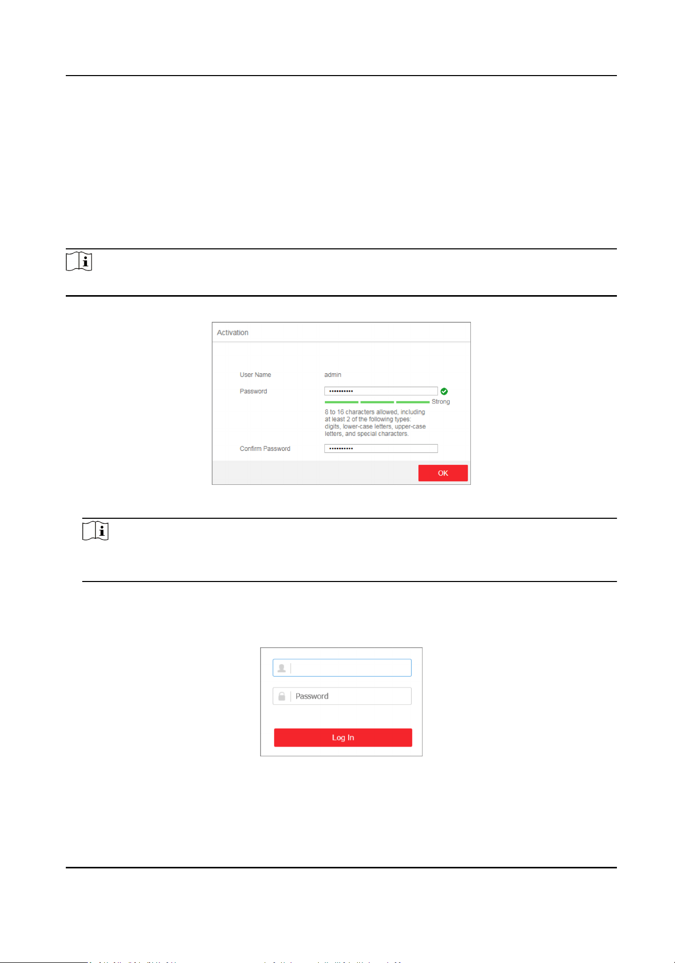
Chapter 2 Acvaon and Login
For the rst me usage, you must acvate the switch and congure the password.
Before You Start
The computer and the switch are on the same network segment.
Steps
Note
Take DS-3E1510P as an example. All gures in this manual are for illustraon purpose only.
1. Enter the default IP 192.168.1.64 in the browser address bar.
Figure 2-1 Acvaon
Note
You are recommended to use the newest version of the following browsers: IE 10+, Edge, and
Chrome 31+.
2. Congure the password and conrm it.
3. Click OK.
Go to the login page.
Figure 2-2 Login
4. Enter the User Name and Password, and click Log In.
5.
Oponal: Change the network conguraon.
Gigabit PoE Switch Web User Manual
2
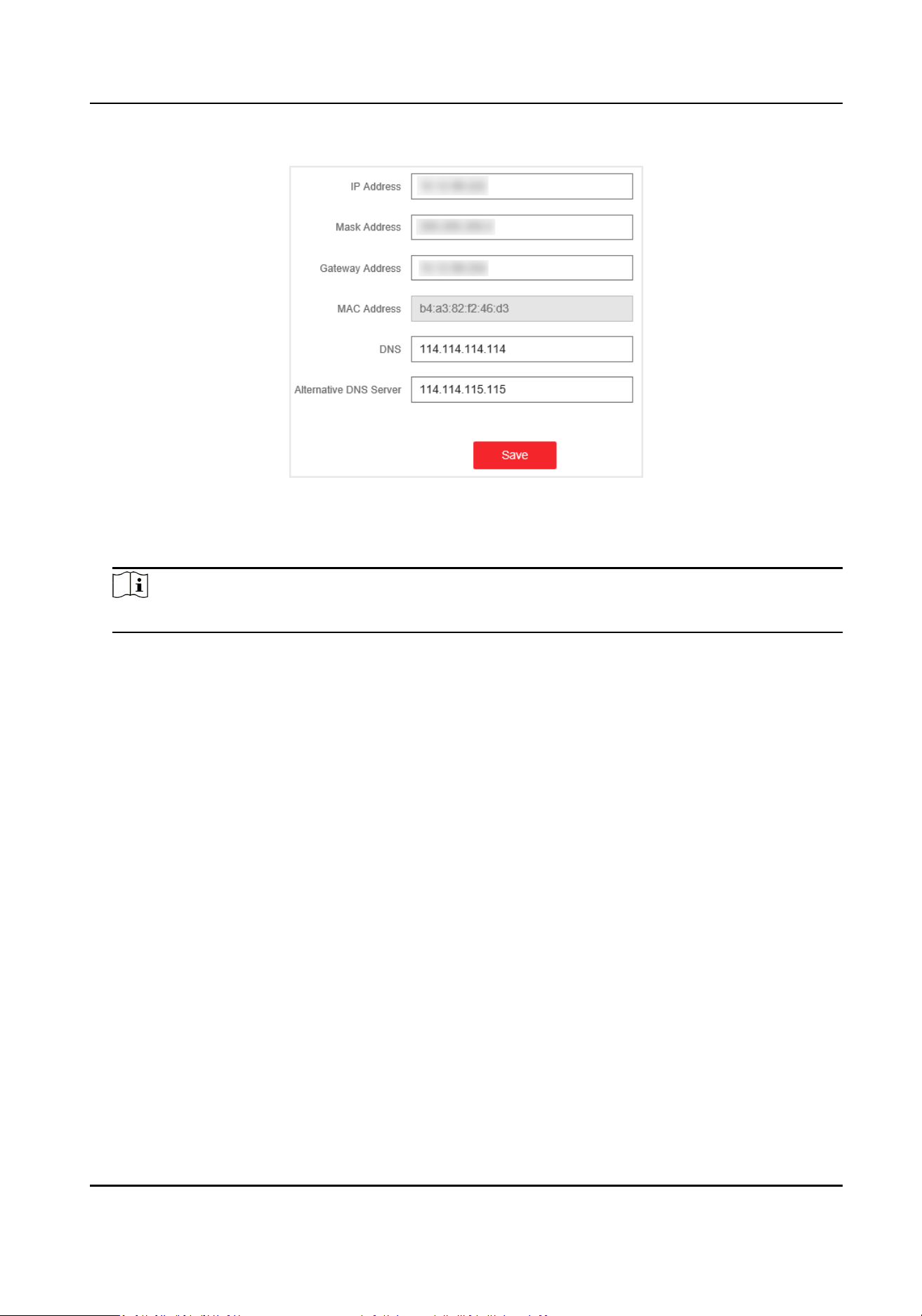
1) Go to System Management → Network Conguraon .
Figure 2-3 Network Conguraon
2) Change the IP address, mask address, the gateway address, DNS and alternave DNS as
needed. You can log in to the switch with the new IP address next me.
Note
You are recommended to change the network conguraon to beer manage the switch.
Gigabit PoE Switch Web User Manual
3
Chapter 3 Device Management
Aer logging in to the Web, you can go to Device Status to view the device status, including the
device
informaon, working status, port status, port stascs, and PoE status.
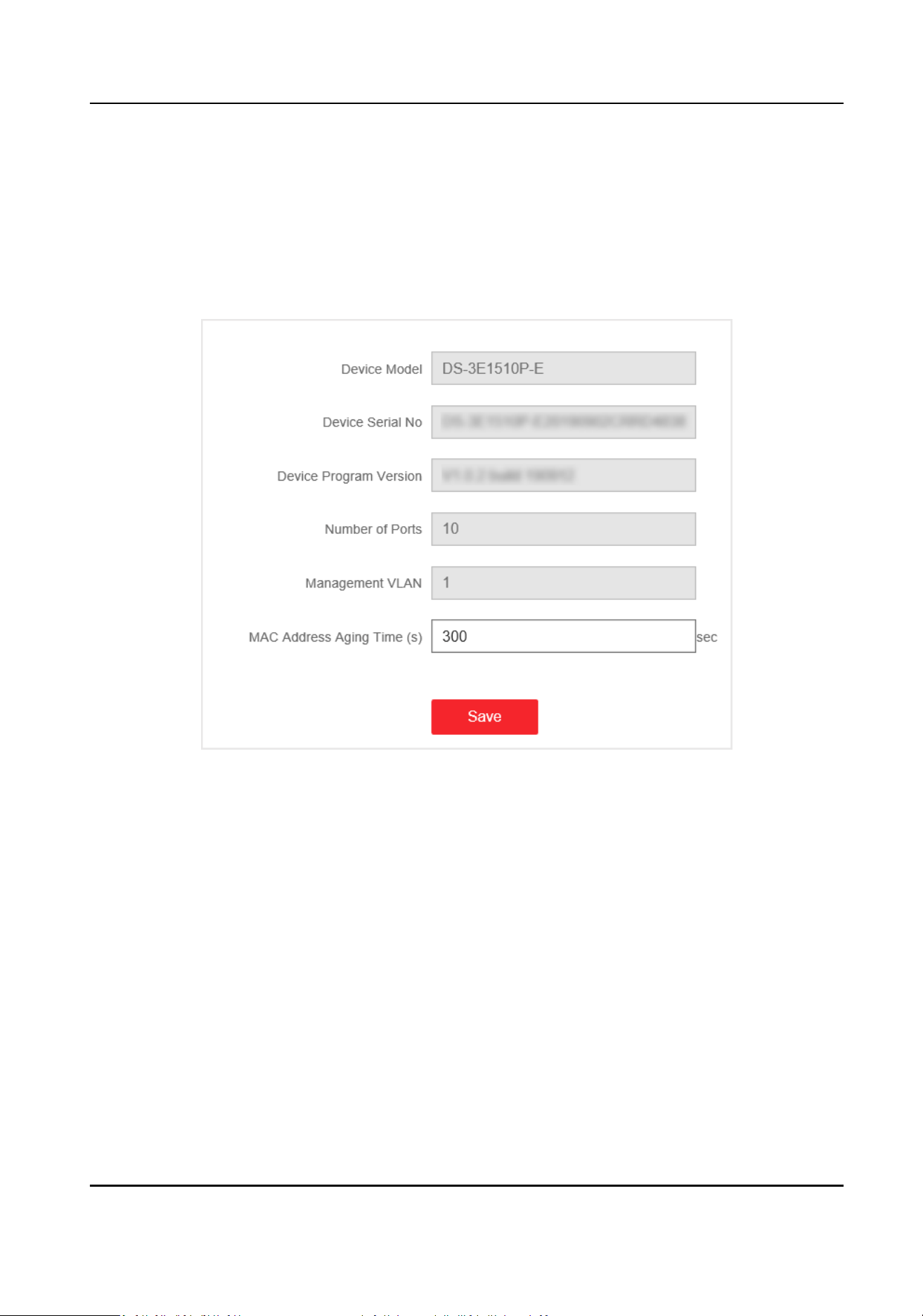
Device Informaon
Figure 3-1 Device Informaon
• Management VLAN: The management VLAN is VLAN 1 by default that cannot be edited.
• MAC Address Aging Time: Aging
me for MAC address table entries. The default is 300 seconds
that cannot be edited.
Gigabit PoE Switch Web User Manual
4
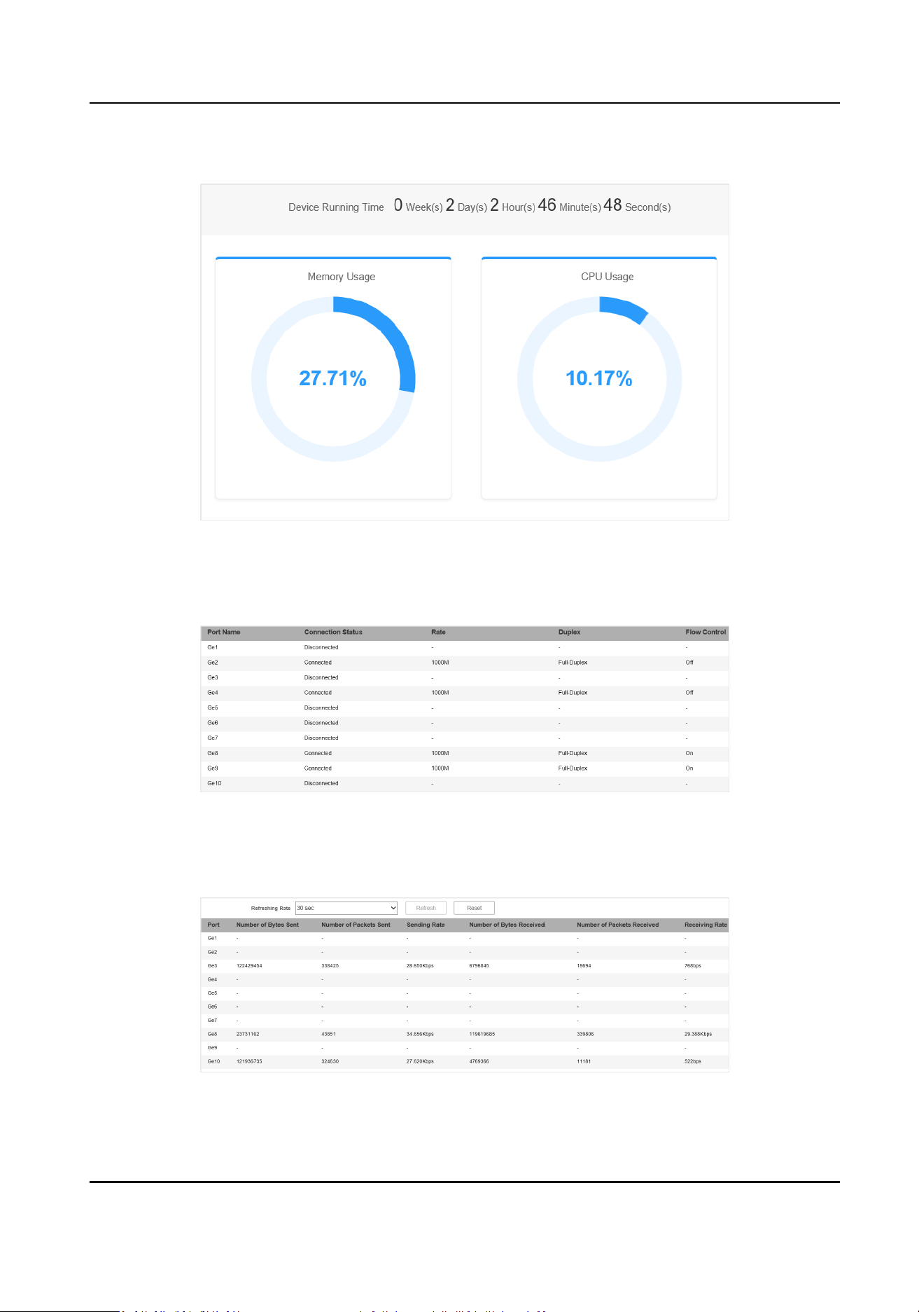
Working Status
Figure 3-2 Working Status
View the device running me, memory usage, and CPU usage.
Port Status
Figure 3-3 Port Status
View the connecon status, rate, duplex, and ow control of all ports.
Port Stascs
Figure 3-4 Port Stascs
Gigabit PoE Switch Web User Manual
5

• Refreshing Rate: 10 sec, 30 sec, 60 sec, and Manually Refresh is available.
• Refresh: When you choose Manually Refresh, you can click Refresh to refresh the
stascs.
• Reset: You can click Reset to clear all the
stascs.
PoE Status
Figure 3-5 PoE Status
View the complete appliance PoE status and the output power of each PoE port.
Gigabit PoE Switch Web User Manual
6
Chapter 4 Switch Conguraon
4.1 Port Conguraon
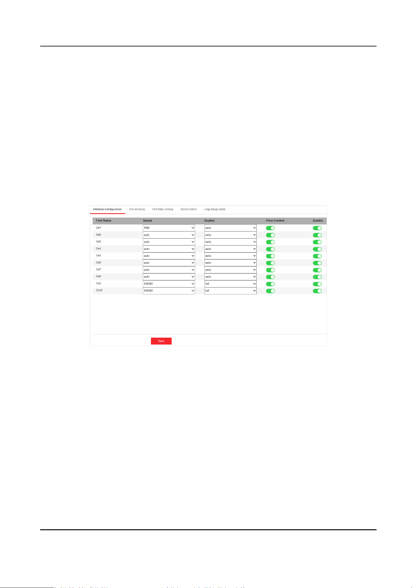
4.1.1 Aribute Conguraon
The basic parameters can inuence the working status of ports. Congure the parameters
according to the actual situaon.
Steps
1. Go to Switch
Conguraon → Basic Conguraon → Port Conguraon → Aribute
Conguraon .
Figure 4-1 Port Aribute Conguraon
2. Congure the parameters.
Speed
The speed of data transmission of the port.
• PoE port: The default is auto.
• SFP
ber opcal port: The default is auto that cannot be edited.
Duplex
The duplex mode of the port.
• PoE port: The default is auto that cannot be edited.
• SFP
ber opcal port: The default is auto that cannot be edited.
Flow Control
Enabling the ow control can prevent data loss in data transmission.
Gigabit PoE Switch Web User Manual
7
Enable
Enable or disable the port link.
3. Click Save to complete the
conguraon.
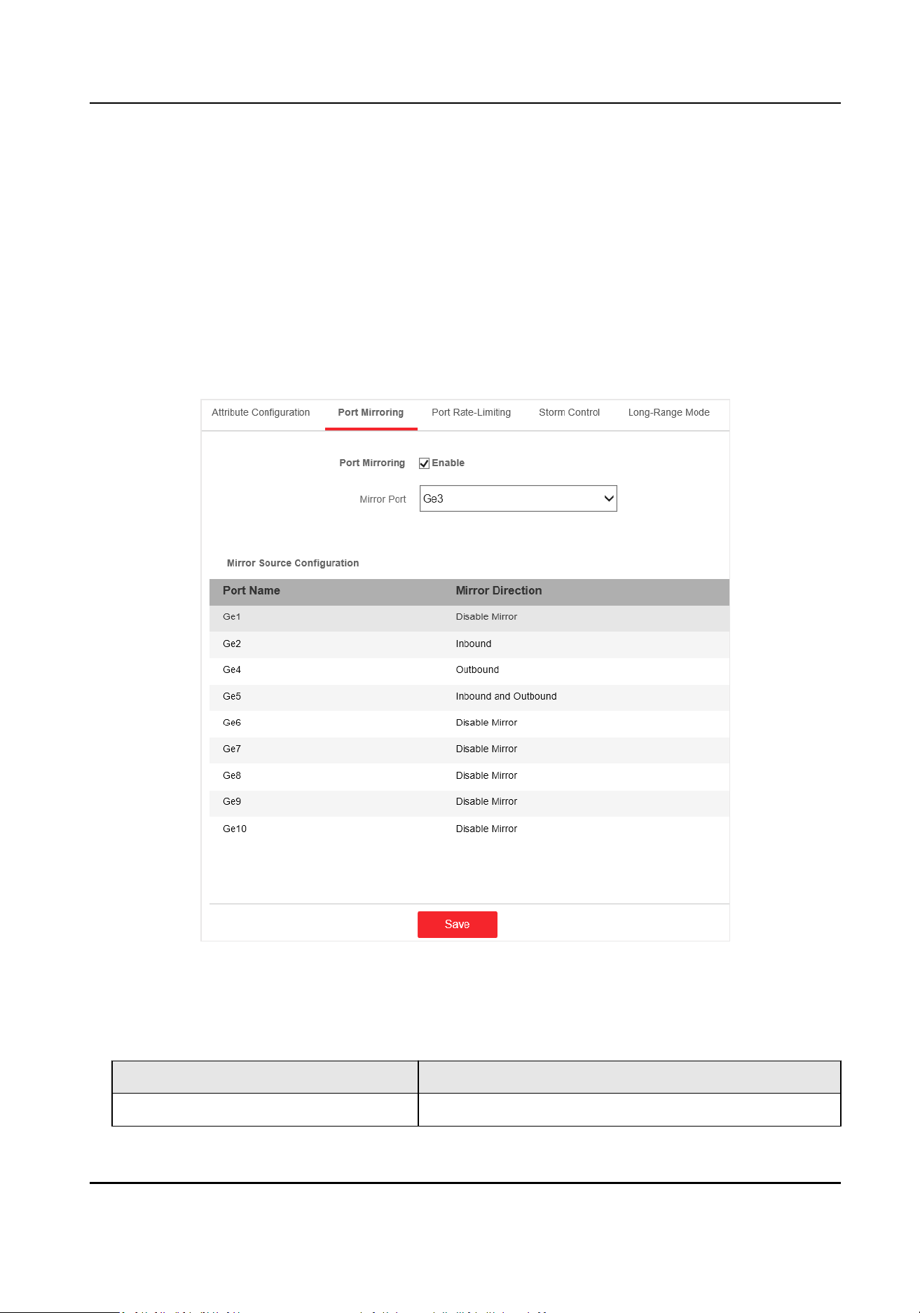
4.1.2 Port Mirroring
Port mirroring monitors network trac by sending copies of all incoming and outgoing packets
from one port to a mirroring port.
Steps
1. Go to Switch
Conguraon → Basic Conguraon → Port Conguraon → Port Mirroring .
Figure 4-2 Port Mirroring
2. Check Enable of Port Mirroring.
3. Congure the parameters according to the actual situaon.
Table 4-1 Parameters of Port Mirroring
Parameter Descripon
Mirror Port Surveillance port.
Gigabit PoE Switch Web User Manual
8
Parameter Descripon
You can only set one port as the mirror port.
Mirror Source The port that is under surveillance.
You can set one or more ports as the mirror source.
Mirror Direcon Surveillance direcon.
• Disable Mirror: The port is not under surveillance.
• Inbound: The inbound data of the port is under
surveillance.
• Outbound: The outbound data of the port is under
surveillance.
• Inbound and Outbound: Both inbound and
outbound data of the port are under surveillance.
4. Click Save to complete the port mirroring conguraon.
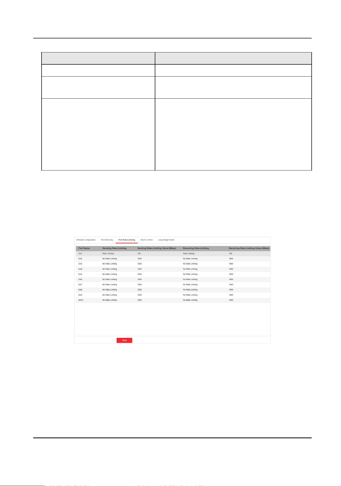
4.1.3 Port
Rate-Liming
Congure the port sending and receiving rate according to the actual situaon.
Steps
1. Go to Switch
Conguraon → Basic Conguraon → Port Conguraon → Port Rate-Liming .
Figure 4-3 Port Rate-Liming
2. Congure the parameters.
Gigabit PoE Switch Web User Manual
9

Table 4-2 Parameters of Port Rate-Liming
Parameter Descripon
Sending Rate-Liming •
Rate-Liming: The data sending rate of the
port is limited.
• No
Rate-Liming: The data sending rate of
the port is not limited.
Sending Rate-Liming Value Only editable when the sending rate of the
port is limited.
The range is from 1 to 1000 Mbps.
Receiving Rate-Liming •
Rate-Liming: The data receiving rate of the
port is limited.
• No
Rate-Liming: The data receiving rate of
the port is not limited.
Receiving Rate-Liming Value Only editable when the receiving rate of the
port is limited.
The range is from 1 to 1000 Mbps.
3. Click Save to complete the conguraon.
4.1.4 Storm Control
Conguraon
Storm control prevents the ports from being disrupted by a broadcast, mulcast, or unknown
unicast storm. Errors in the protocol-stack
implementaon, or mistakes in network conguraon,
can cause a storm. The storm congests the network and degrades the network performance.
The packets passing from the port will be determined by the storm control if they are unknown
unicast,
mulcast, or broadcast. When the packets number exceeds the threshold, the incoming
data is dropped.
Steps
1. Go to Switch
Conguraon → Basic Conguraon → Port Conguraon → Storm Control .
Gigabit PoE Switch Web User Manual
10

Figure 4-4 Storm Control
2. Select the port on which you want to enable storm control. Congure Storm Control as on.
3. Congure Storm Control Mode as Broadcast, Mulcast, or Unknown Unicast. The threshold
applies to the chosen mode.
4.
Congure the number of frames in Mbps that you want the port to handle in Rate Threshold.
5. Click Save to complete the
conguraon.
4.1.5 Long-Range Mode
Conguraon
When long-range mode is enabled, the transmission distance of the port can reach 300 meters,
and the rate is 10 Mbps.
Steps
1. Go to Switch
Conguraon → Basic Conguraon → Port Conguraon → Long-Range Mode .
Gigabit PoE Switch Web User Manual
11
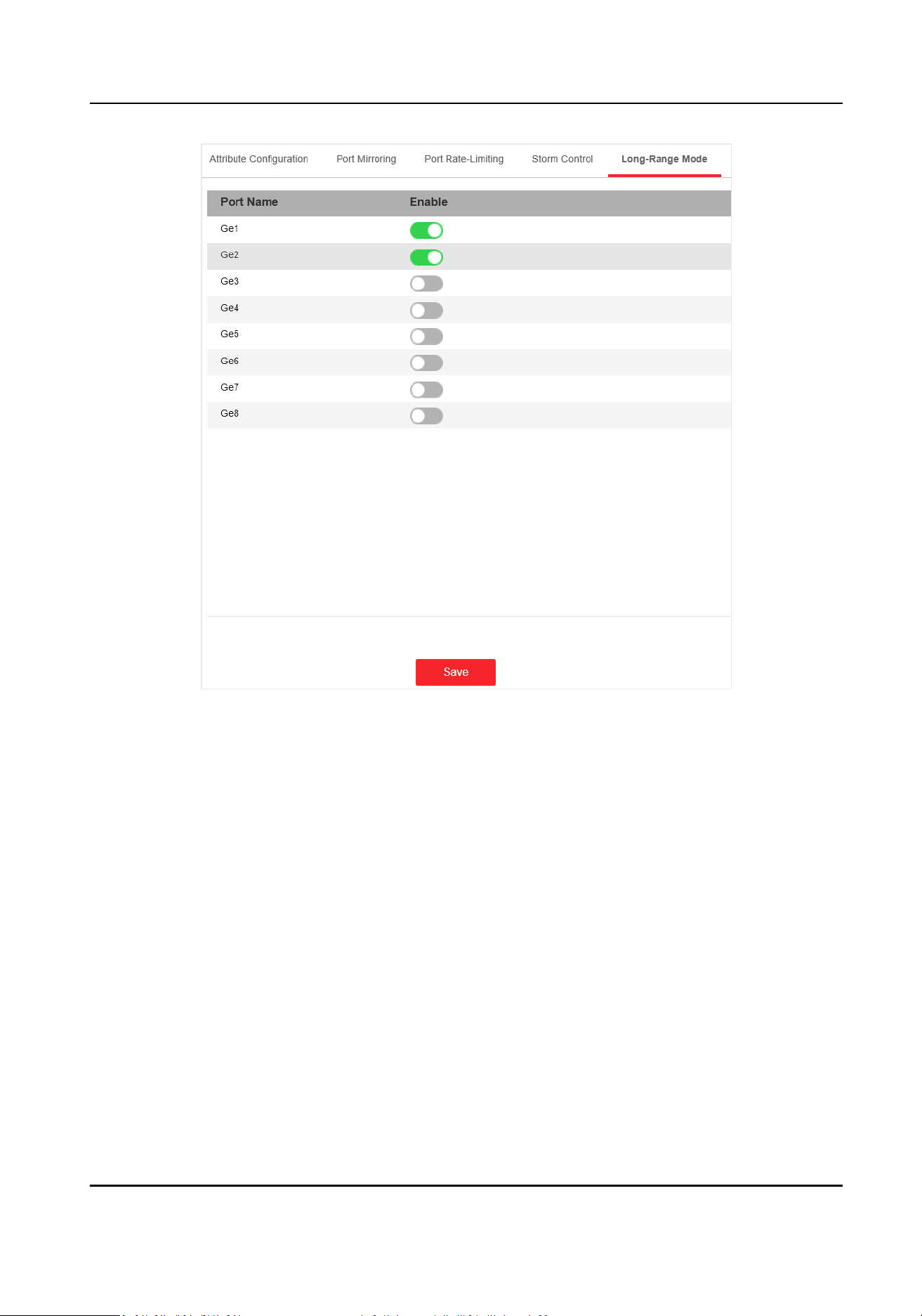
Figure 4-5 Long-Range Mode Conguraon
2. Check Enable of the port.
3. Click Save to complete the conguraon.
4.2 Link
Aggregaon Conguraon
Link aggregaon is used to aggregate physical ports to create a logical channel. The advantages of
link
aggregaon are higher transmission speed with wider bandwidth.
Steps
1. Go to Switch Conguraon → Basic Conguraon → Link Aggregaon → Load Balancing
Conguraon to congure Load Balancing Mode.
Gigabit PoE Switch Web User Manual
12
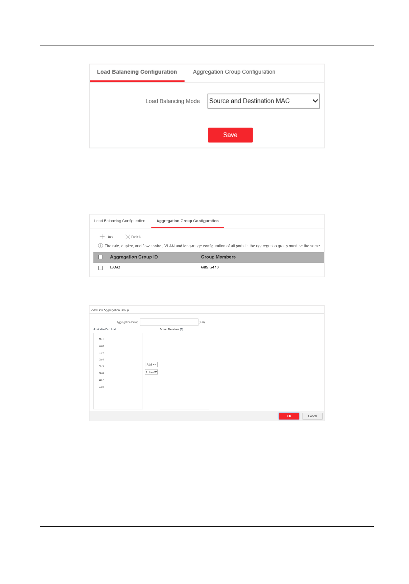
Figure 4-6 Load Balancing
Source and Desnaon MAC
Load balancing is performed based on source and desnaon MAC addresses on all the
packets.
2. Add a link aggregaon group in Aggregaon Group Conguraon.
Figure 4-7 Link Aggregaon Group
1) Click Add.
Figure 4-8 Add a Link Aggregaon Group
2) Enter the group number in the Aggregaon Group eld. The range is from 1 to 8.
3) Move the ports that are to be assigned to the group from the Available Port List to the
Group Members list.
Gigabit PoE Switch Web User Manual
13
Note
• You can delete the ports from the Group Members by clicking Delete.
• The rate, duplex,
ow control, VLAN, and long-range conguraon of all ports in one
aggregaon group must be the same.
4) Click OK to add a link aggregaon group.
4.3 VLAN Conguraon
A Virtual Local Area Network (VLAN) is a group of devices located on dierent LAN segments that
are congured to communicate as if they were aached to the same wire. LANs are based on
logical instead of physical connecons, which is exible for device connecon.
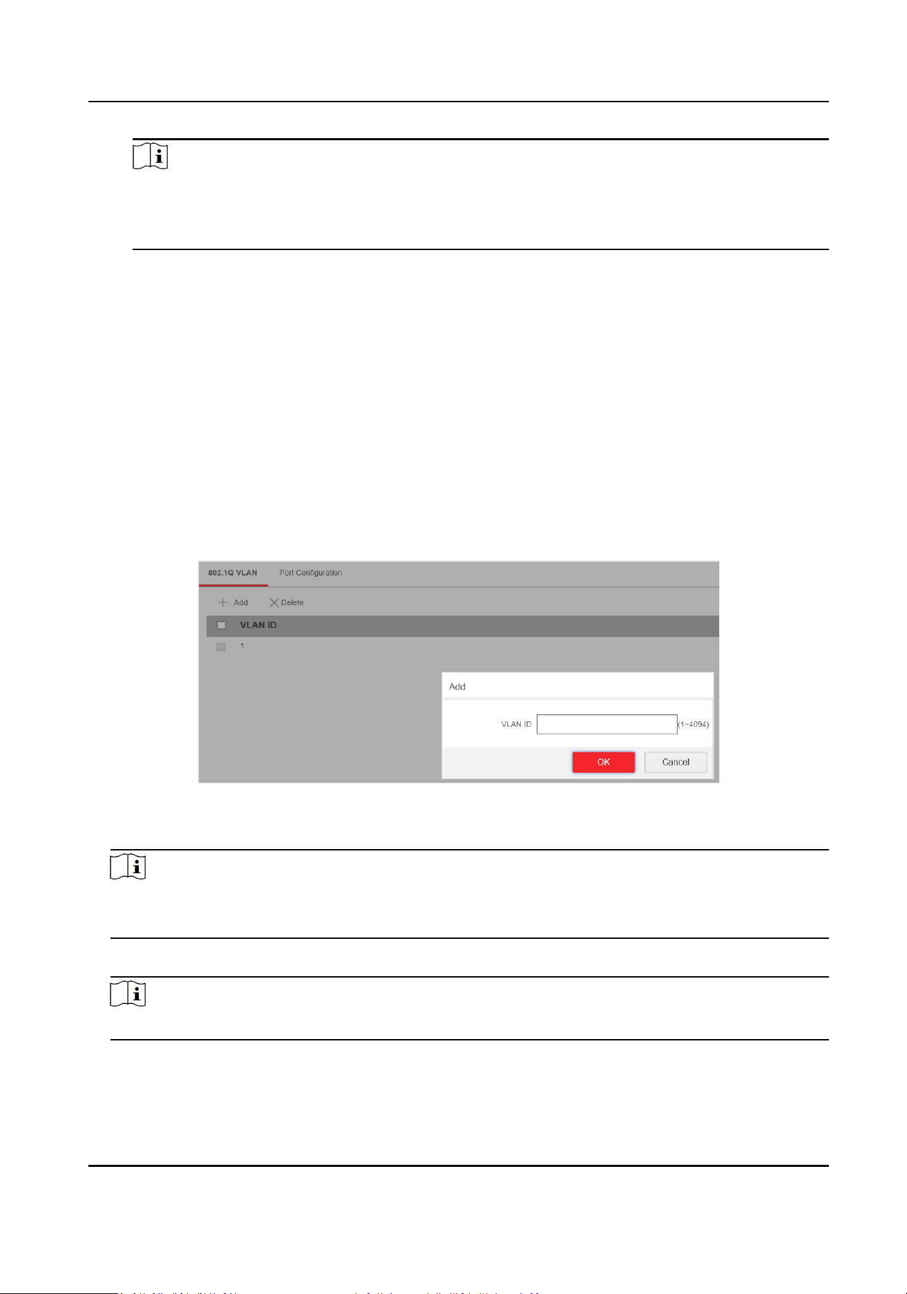
4.3.1 Add a VLAN
Steps
1. Go to Switch
Conguraon → Basic Conguraon → VLAN → 802.1Q VLAN .
2. Click Add.
Figure 4-9 Add a VLAN
3.
Enter a VLAN ID.
Note
• A maximum of 128 VLANs are supported.
• The range is from 1 to 4094.
4. Oponal: You can also delete a VLAN by clicking Delete.
Note
You cannot delete the VLAN 1, because VLAN 1 is the Management VLAN.
Gigabit PoE Switch Web User Manual
14
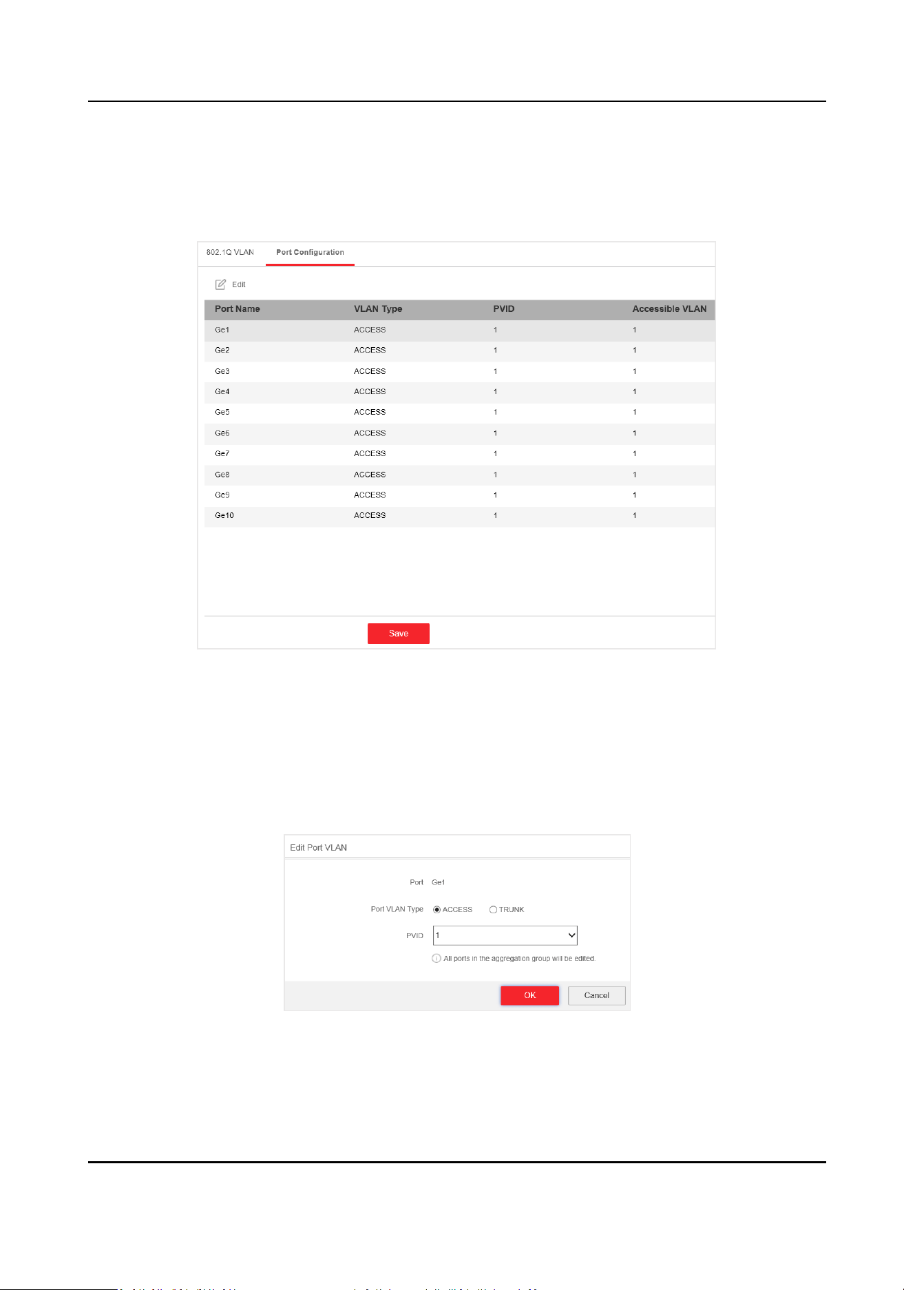
4.3.2 Congure a Port
Steps
1. Select a port to
congure on the Port Conguraon page.
Figure 4-10 VLAN Port Conguraon
2. Click Edit.
3.
Congure the port VLAN.
-
Access Port
• An access port transports
trac to and from only the specied VLAN, usually the
default VLAN, VLAN 1.
• Select Port VLAN Type as ACCESS, and select the PVID.
Figure 4-11 Edit an Access Port VLAN
Gigabit PoE Switch Web User Manual
15
Note
All ports in the same aggregaon group will be edited automacally at the same me.
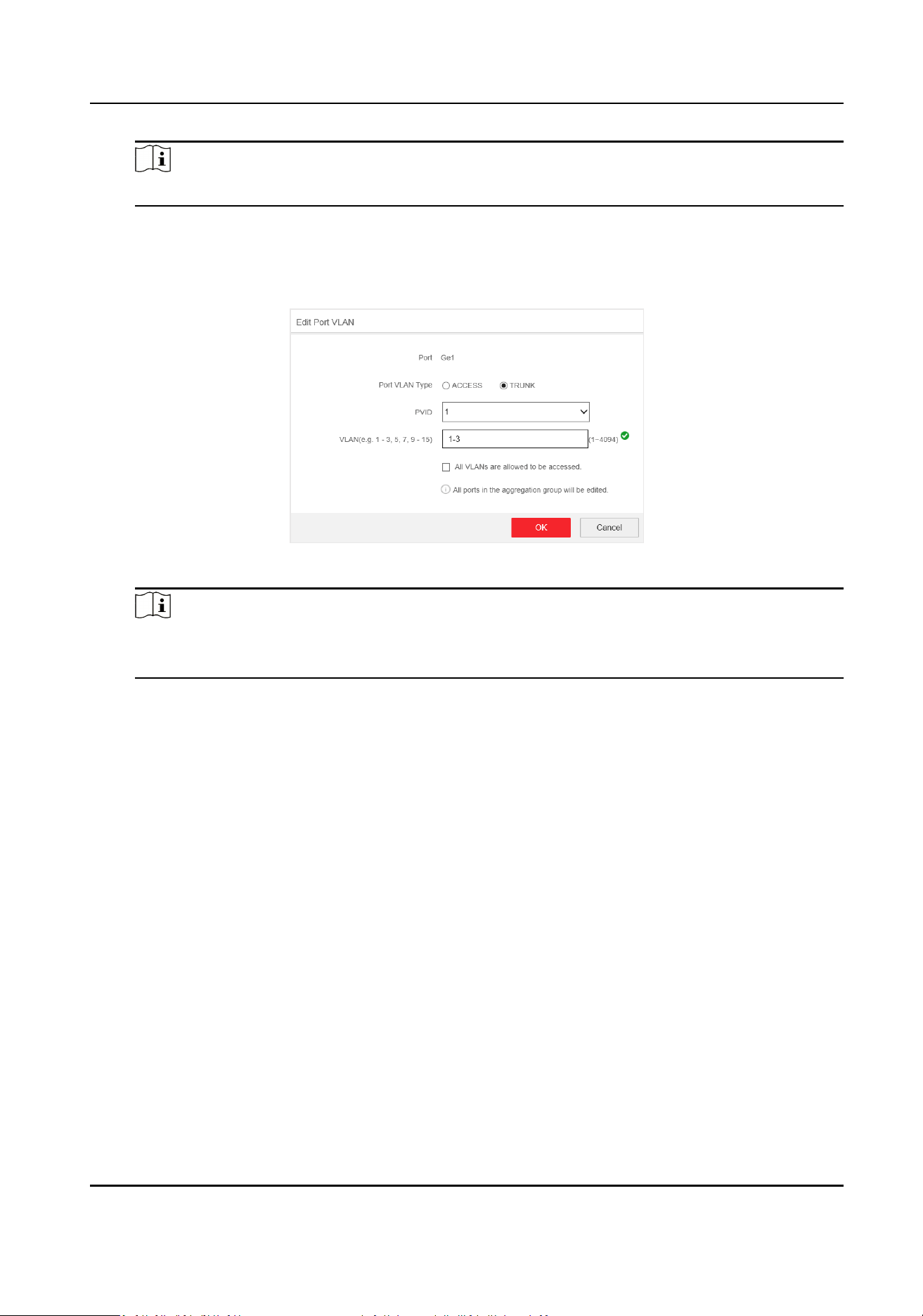
-
Trunk Port
•
A trunk port is a port that is assigned to carry
trac for all the VLANs.
• Select Port VLAN Type as TRUNK, select the PVID and enter the VLAN that are allowed
to be accessed.
Figure 4-12 Edit a Trunk Port VLAN
Note
• All ports in the same
aggregaon group will be edited automacally at the same me.
• You can check All VLANS are allowed to be accessed. to assign the port to all the VLANs.
4. Click OK.
5. Click Save to save the conguraon.
4.4 QoS
Conguraon
Quality of Service (QoS) includes the transmission bandwidth, delay, packet loss rate and etc.
Increasing network bandwidth, decreasing network delay, and reducing packet losses can improve
QoS in network service. You can congure the scheduling mode and port priority of QoS.
Steps
1. Go to Switch
Conguraon → Basic Conguraon → QoS → Scheduling Mode to select a
scheduling type.
Gigabit PoE Switch Web User Manual
16

Figure 4-13 Scheduling Mode
NORMAL
First In First Out (FIFO) mode. Transmit the message coming in rst. QoS is not enabled.
SP
Strict Priority mode. Transmit the message according to the actual priority conguraon.
WRR
Weighted Round Robin mode. Transmit the message according to the respecve weight for
low priority and high priority.
2.
Congure the port priority in Port Priority.
Gigabit PoE Switch Web User Manual
17
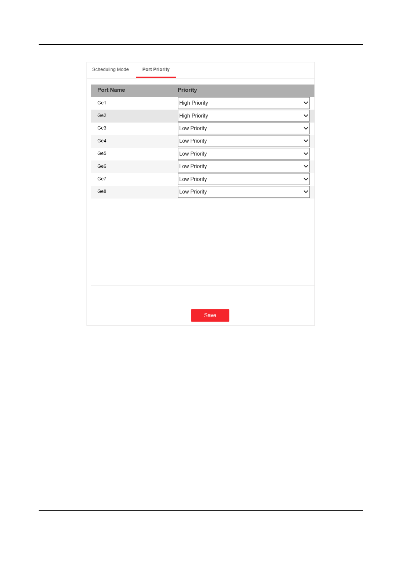
Figure 4-14 Port Priority
3. Click Save to complete the conguraon.
4.5 SNMP
Conguraon
Simple Network Management Protocol (SNMP) is a widely used applicaon-layer communicaon
protocol for monitoring network performance. SNMP network is composed of the Network
Management System (NMS) and the Agent. NMS is the SNMP manager, and Agent sends Traps to
NMS.
Gigabit PoE Switch Web User Manual
18
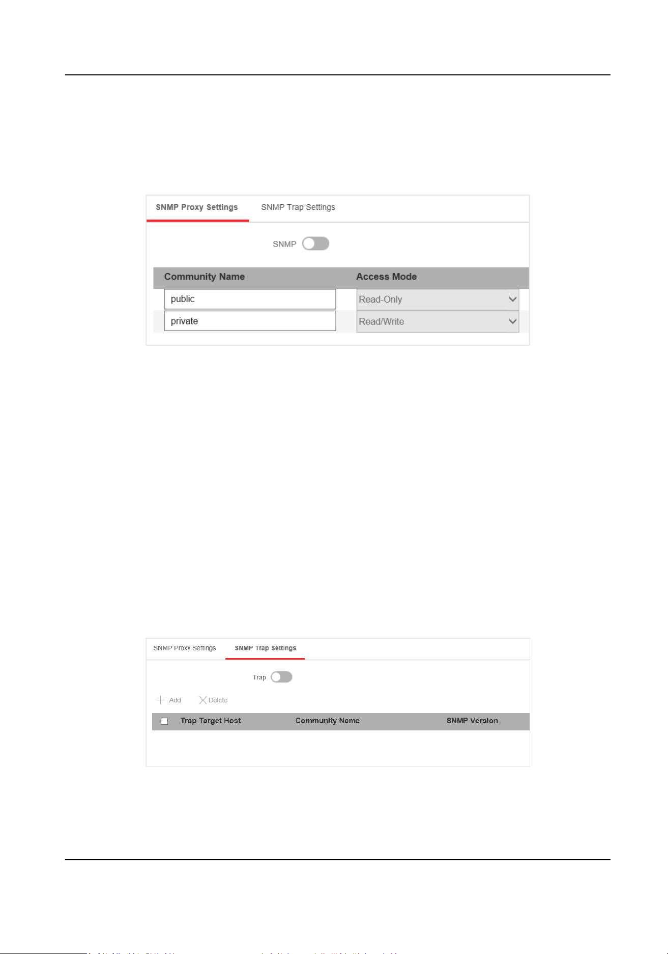
4.5.1 SNMP Proxy Sengs
Steps
1. Go to Switch
Conguraon → L2 Conguraon → SNMP Conguraon → SNMP Proxy Sengs
to congure SNMP proxy.
Figure 4-15 Proxy Sengs
1) Enable SNMP.
2)
Dene the Community Name.
Community Name
The community name is an
authencaon mechanism, similar to a password, which is
used to limit the data transmission between NMS and Agent.
• Read-Only Community Name: The Community name accessible to NMS with read
permission. The default is public.
• Read/Write Community Name: The Community name accessible to NMS with read and
write permission. The default is private.
3) Click Save.
4.5.2 SNMP Trap
Sengs
Steps
1. Enable Trap on the SNMP Trap
Sengs page.
Figure 4-16 Trap Sengs
2. Click Add to add a trap.
Gigabit PoE Switch Web User Manual
19

Figure 4-17 Add a Trap
Table 4-3 Parameters of a Trap
Parameter Descripon
Target Host IP The IP address of NMS. It cannot be the broadcast or
mulcast address.
Community Name The password used for authencaon. Up to 32 bytes can
be set.
SNMP Version The Agent supports SNMP Version 1 (SNMPv1) and SNMP
Version 2c (SNMPv2c).
Note
The prerequisite of successful connecon between NMS
and Agent is that the SNMP version of NMS and Agent
must be the same.
3. Click OK.
4. Click Save to add a trap.
5.
Oponal: You can check the trap and click Delete to delete a trap.
4.6 STP
Conguraon
Spanning-Tree Protocol (STP) is a Layer 2 link management protocol that provides path redundancy
while prevenng loops in the network. The STP uses a spanning-tree algorithm to select one switch
as the root of a spanning tree. STP determines the topology by
transming Bridge Protocol Data
Unit (BPDU) packets between devices. Spanning-tree operaon creates a stable network.
4.6.1 Global
Conguraon
Steps
1. Go to Switch Conguraon → L2 Conguraon → STP Conguraon → Global Conguraon .
2. Check Enable STP.
Gigabit PoE Switch Web User Manual
20
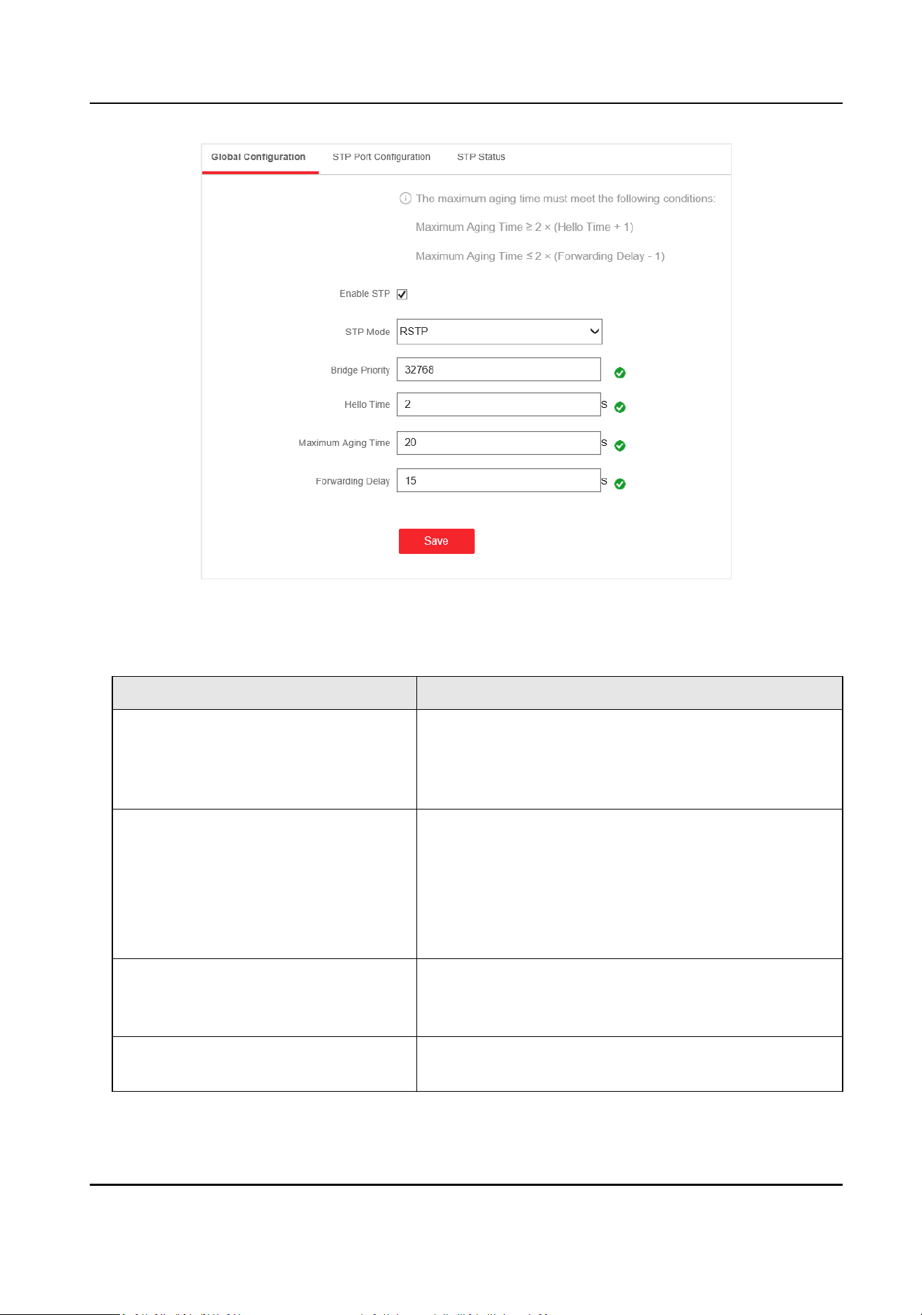
Figure 4-18 Global Conguraon
3. Congure the parameters.
Table 4-4 Parameters of STP
Parameter Descripon
STP Mode • STP: Spanning-tree protocol.
• RSTP: Rapid spanning-tree protocol. RSTP provides
faster spanning tree convergence
aer a topology
change.
Bridge Priority The lower the number is, the higher the priority is.
The range is from 0 to 61,440 seconds, in increments
of 4096; the default is 32,768. Valid values are 0, 4096,
12288, 16384 ... and 61440.
A switch with higher bridge priority is more likely to
become a root bridge.
Hello Time The me between each BPDU that is sent on a port,
which is used for port link diagnosis. The range is from
1 to 10 seconds. The default is 2 seconds.
Maximum Aging Time The maximum length of me that passes before a
bridge port saves its conguraon BPDU informaon.
Gigabit PoE Switch Web User Manual
21

Parameter Descripon
The range is from 6 to 40 seconds. The default is 20
seconds.
Note
The maximum aging me must meet the following
condions:
• Maximum Aging Time ≥ (Hello Time + 1)
• Maximum Aging Time ≤ (Forwarding Delay - 1)
Forwarding Delay The me interval that is spent in the listening and
learning state when the topology changes. The range
is from 4 to 30 seconds. The default is 15 seconds.
4. Click Save.
4.6.2 STP Port
Conguraon
If a loop occurs, you can set port priority so that the spanning tree can select the port with the
highest priority to forward data.
Steps
1. The port is enabled by default on the STP Port
Conguraon page.
Gigabit PoE Switch Web User Manual
22
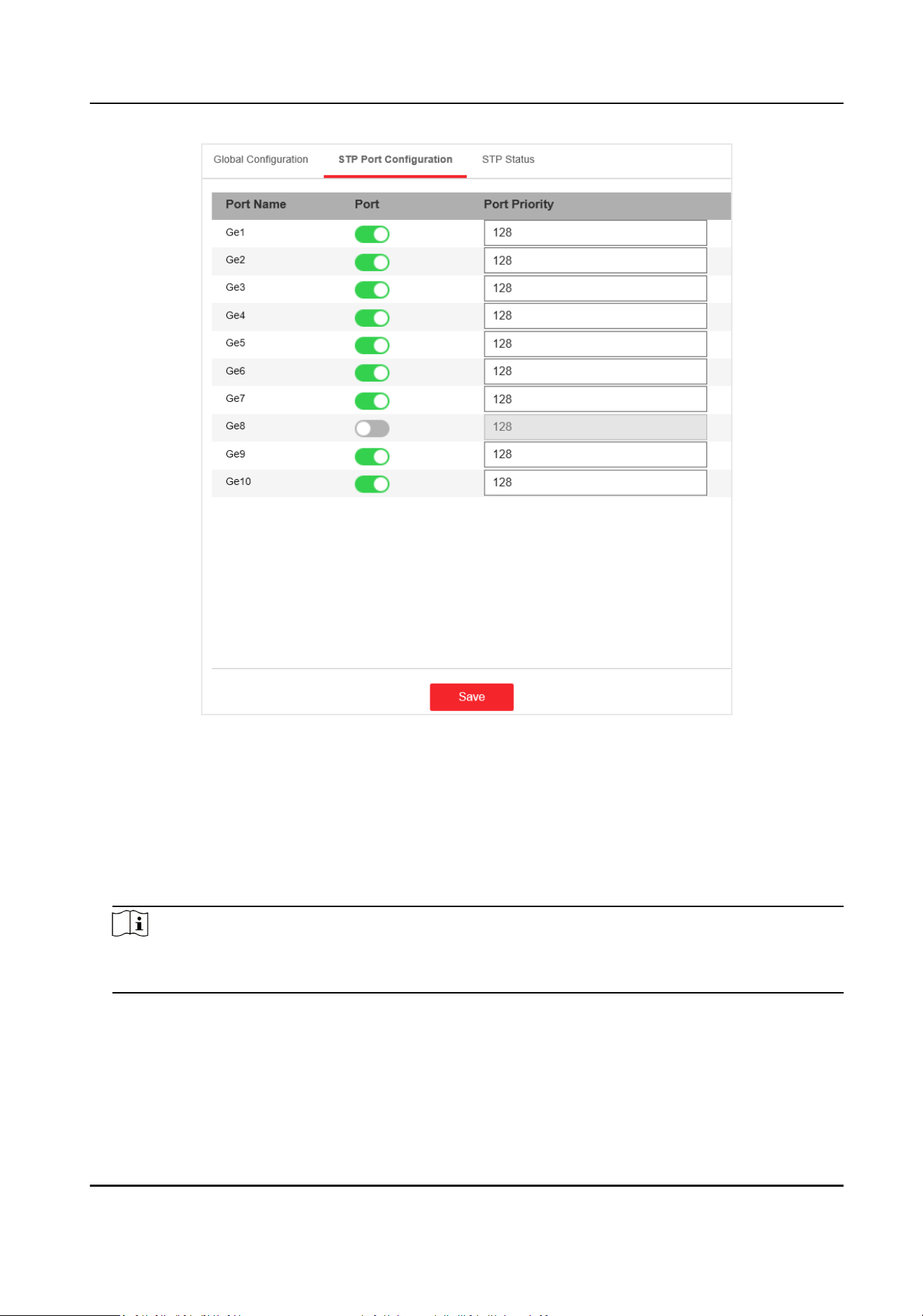
Figure 4-19 Port Priority
2.
Congure the Port Priority.
Port Priority
• The lower the number is, the higher the priority is, the more probably the port becomes
the root port.
• The range is from 0 to 240, in increments of 16; the default is 128. Valid values are 0, 16,
32, 48, 64, 80, 96, 112, 128, 144, 160, 176, 192, 208, 224, and 240.
Note
If the priority of the port is the same, spanning tree uses the port ID to select a port as the root
port.
3. Click Save.
Gigabit PoE Switch Web User Manual
23
4.6.3 STP Status View
You can check the global status of STP sengs and the status of each port.
Go to Switch
Conguraon → L2 Conguraon → STP Conguraon → STP Status .
Figure 4-20 STP Status
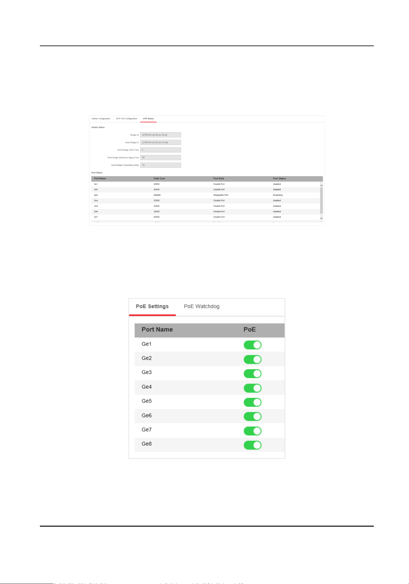
4.7 PoE Management
PoE Sengs
Figure 4-21 PoE Sengs
You can enable PoE to supply power for the powered devices (PDs).
Gigabit PoE Switch Web User Manual
24

Note
Enabling or disabling PoE has no inuences on data transmission of the port.
PoE Watchdog
Figure 4-22 PoE Watchdog
You can enable PoE watchdog to auto-detect and restart cameras that do not respond.
Gigabit PoE Switch Web User Manual
25
Chapter 5 System Management
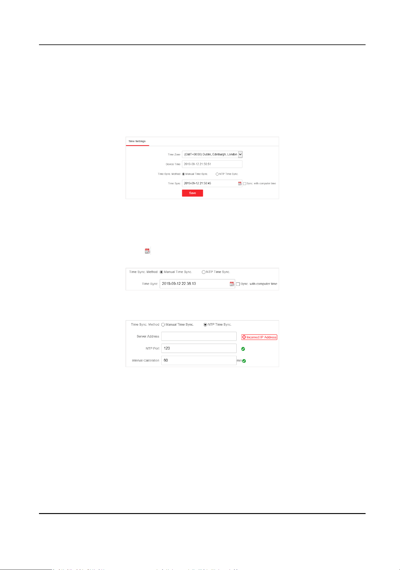
5.1 Time Sync
Steps
1. Go to System
Sengs → Time Sengs . You can view the Device Time.
Figure 5-1 Time Sengs
2. Select Time Zone.
3. Select Time Sync. Method
4. Set me synchronizaon mode.
-
Manual Time Sync.: Click
or check Sync. with computer me to synchronize the device
me.
Figure 5-2 Manual Sync
-
NTP Time Sync.: Enter the NTP Server Address, and set the me sync. interval.
Figure 5-3 NTP Sync
5. Click Save.
5.2 Device
Operaon
When the switch malfuncons or fails to work properly, you can go to System Management →
System Maintenance → Device
Operaon to restart or restore the switch.
Gigabit PoE Switch Web User Manual
26
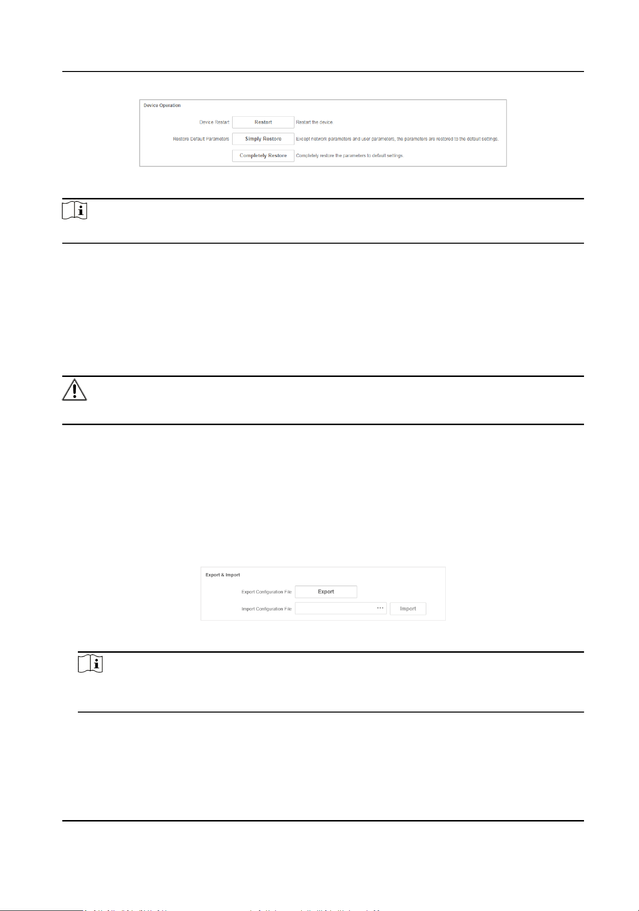
Figure 5-4 Device Operaon
Note
Enter the login page automacally aer you restart or restore the switch.
Restart
Click Restart to remotely restart the switch.
Restore
• Simply Restore: Except network conguraon and user parameters, all of the other parameters
are restored to the default sengs.
• Completely Restore: Completely restore the parameters to default sengs.
Cauon
Parameters cannot be recovered aer being restoring to default sengs.
5.3 Conguraon File Export
You can export the conguraon le for local backup.
Steps
1. Go to System Management → System Maintenance → Export & Import .
2. Click Export.
3. Set a password for the exported
conguraon le.
Figure 5-5 Export
Conguraon le
Note
Please remember the password, because you need to enter the password when imporng the
conguraon les.
4. Click OK.
Gigabit PoE Switch Web User Manual
27

5.4 Conguraon File Import
You can import the conguraon le to congure the system easily.
Steps
1. Go to System Management → System Maintenance → Export & Import .
Figure 5-6 Export Conguraon le
2. Click to select the conguraon le.
3. Click Import.
The device will restart
automacally to enter the login page when the conguraon le is
imported.
5.5 Device Upgrade
You can upload the upgrade le to upgrade your switch.
Steps
1. Go to System Management → System Maintenance → Device Upgrade
Figure 5-7 Upgrade
2. Click to select an upgrade patch.
3. Click Upgrade.
Note
If upgrading failed or the device cannot funcon, please contact our technical support
engineers.
Result
The device will restart automacally to enter the login page when upgrade nished.
5.6 Log Management
System operaon logs can be searched and exported for backup.
Gigabit PoE Switch Web User Manual
28
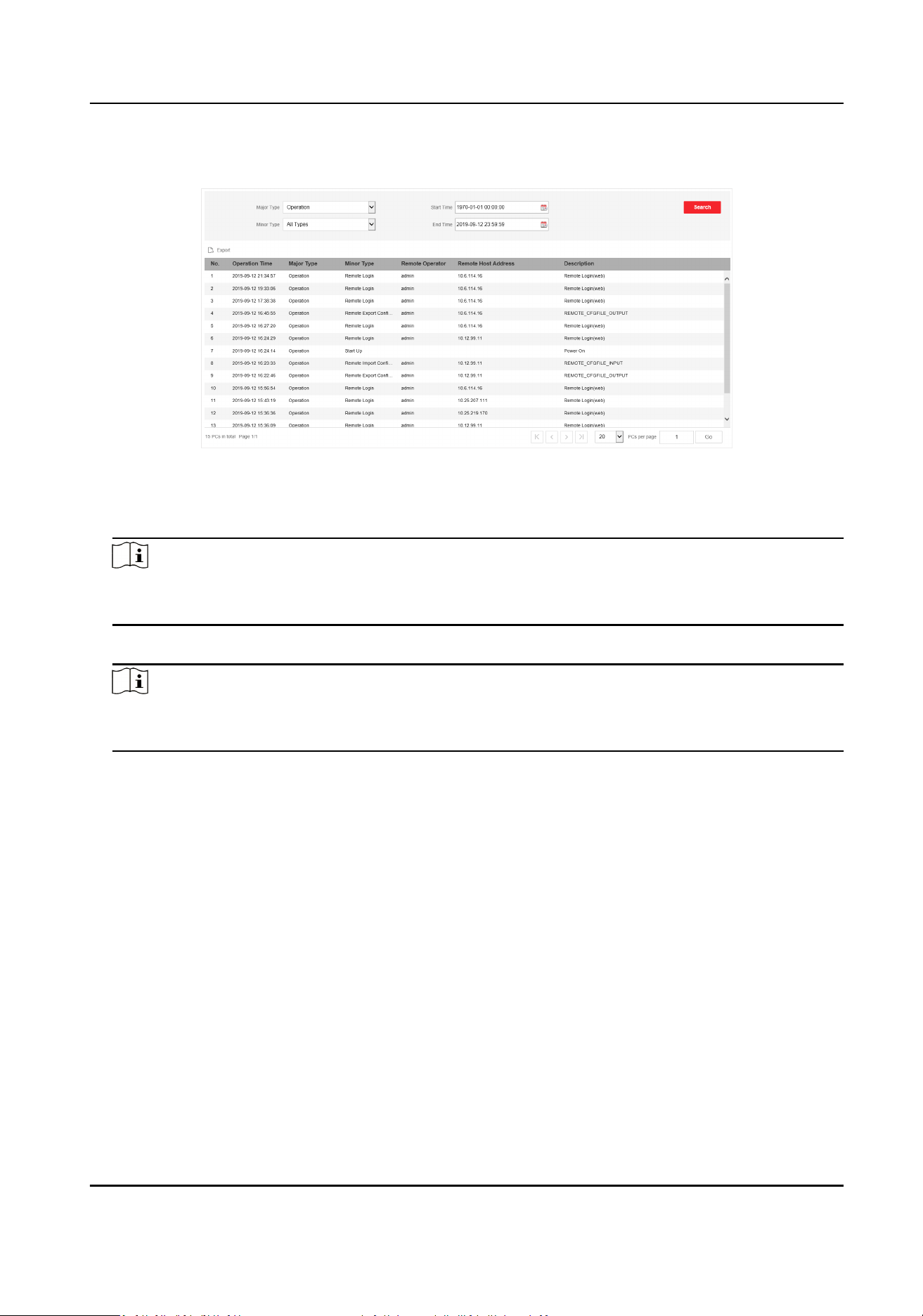
Steps
1. Go to System Management → Log Management .
Figure 5-8 Log Management
2. Set search condions, including Major Type, Minor Type, Start Time and End Time.
3. Click Search.
Note
A maximum of 2000 search results can display. Please narrow down the search scope if there
are too many search results.
4. Oponal: Click Export to export all the search results.
Note
Logs can be exported in Excel. A prompt window will pop up when the logs are exported
successfully.
5.7 Network Diagnoscs
With network diagnoscs, troubleshoong engineers can locate network faults quickly.
Steps
1. Go to System Management → System Tools → Network Diagnoscs .
Gigabit PoE Switch Web User Manual
29
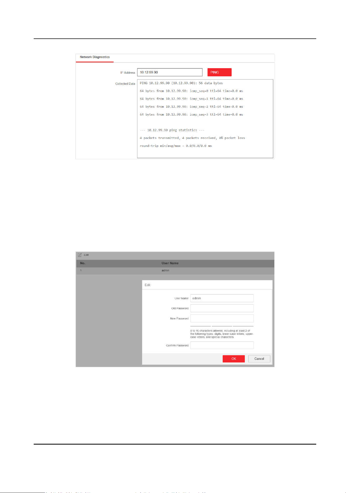
Figure 5-9 Network Diagnoscs
2. Enter the IP address of the server, and click PING.
5.8 User Management
Regularly change the password can guarantee the security of the device.
Steps
1. Go to System Management → User Management .
2. Click Edit.
Figure 5-10 User Management
3. Enter the old password.
4. Enter a new password and conrm it.
5. Click OK.
Gigabit PoE Switch Web User Manual
30
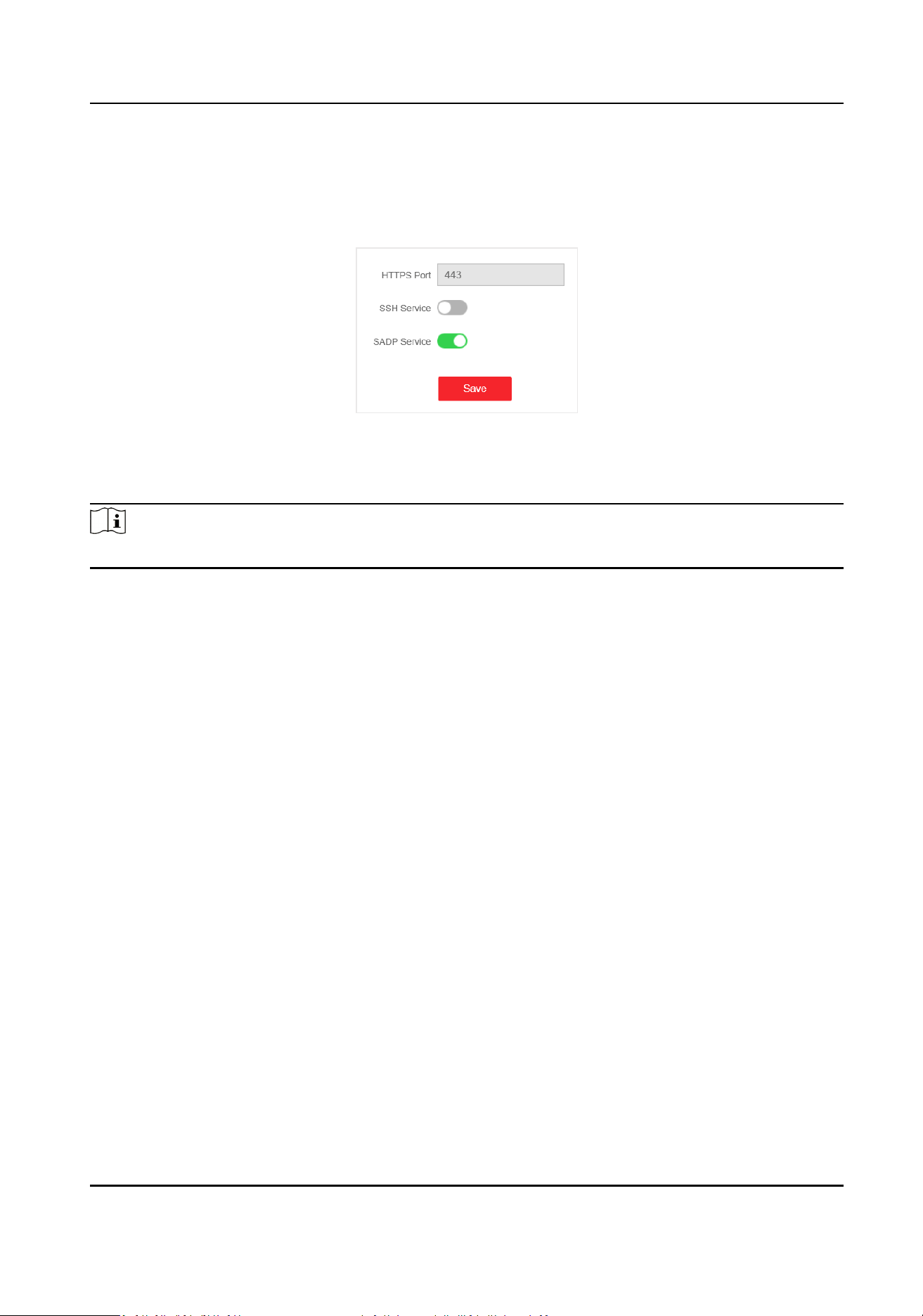
5.9 Security Management
SSH
Figure 5-11 Security Management
The device supports SSH security service. SSH can prevent the informaon leakage in the remote
management of the device. SSH is disabled by default.
Note
The user name of SSH is root, and the password is the device login password.
SADP
Aer enabling SADP, you can acvate the device, change the password and the network
informaon, and etc. SADP is enabled by default.
Gigabit PoE Switch Web User Manual
31

UD18556B