
Smart Managed Switch Client
User Manual
UD33917B

Legal Informaon
About this Document
●
This Document includes instrucons for using and managing
the Product. Pictures, charts, images and all other informaon
hereinaer are for descripon and explanaon only.
●
The informaon contained in the Document is subject to
change, without noce, due to rmware updates or other
reasons. Please nd the latest version of the Document at the
Hikvision website (
hps://www.hikvision.com ). Unless
otherwise agreed, Hangzhou Hikvision Digital Technology Co.,
Ltd. or its aliates (hereinaer referred to as "Hikvision")
makes no
warranes, express or implied.
●
Please use the Document with the guidance and assistance of
professionals trained in supporng the Product.
About this Product
This product can only enjoy the aer-sales service support in the
country or region where the purchase is made.
Acknowledgment of Intellectual Property Rights
●
Hikvision owns the copyrights and/or patents related to the
technology embodied in the Products described in this
Document, which may include licenses obtained from third
pares.
●
Any part of the Document, including text, pictures, graphics,
etc., belongs to Hikvision. No part of this Document may be
excerpted, copied, translated, or
modied in whole or in part
by any means without wrien permission.
●
and other Hikvision's trademarks and logos are
the properes of Hikvision in various jurisdicons.
●
Other trademarks and logos menoned are the properes of
their respecve owners.
LEGAL DISCLAIMER
●
TO THE MAXIMUM EXTENT PERMITTED BY APPLICABLE LAW,
THIS DOCUMENT AND THE PRODUCT DESCRIBED, WITH ITS
HARDWARE, SOFTWARE AND FIRMWARE, ARE PROVIDED "AS
IS" AND "WITH ALL FAULTS AND ERRORS". HIKVISION MAKES
NO WARRANTIES, EXPRESS OR IMPLIED, INCLUDING WITHOUT
LIMITATION, MERCHANTABILITY, SATISFACTORY QUALITY, OR
FITNESS FOR A PARTICULAR PURPOSE. THE USE OF THE
PRODUCT BY YOU IS AT YOUR OWN RISK. IN NO EVENT WILL
HIKVISION BE LIABLE TO YOU FOR ANY SPECIAL,
CONSEQUENTIAL, INCIDENTAL, OR INDIRECT DAMAGES,
INCLUDING, AMONG OTHERS, DAMAGES FOR LOSS OF
BUSINESS PROFITS, BUSINESS INTERRUPTION, OR LOSS OF
DATA, CORRUPTION OF SYSTEMS, OR LOSS OF
DOCUMENTATION, WHETHER BASED ON BREACH OF
CONTRACT, TORT (INCLUDING NEGLIGENCE), PRODUCT
LIABILITY, OR OTHERWISE, IN CONNECTION WITH THE USE OF
i

THE PRODUCT, EVEN IF HIKVISION HAS BEEN ADVISED OF THE
POSSIBILITY OF SUCH DAMAGES OR LOSS.
●
YOU ACKNOWLEDGE THAT THE NATURE OF THE INTERNET
PROVIDES FOR INHERENT SECURITY RISKS, AND HIKVISION
SHALL NOT TAKE ANY RESPONSIBILITIES FOR ABNORMAL
OPERATION, PRIVACY LEAKAGE OR OTHER DAMAGES
RESULTING FROM CYBER-ATTACK, HACKER ATTACK, VIRUS
INFECTION, OR OTHER INTERNET SECURITY RISKS; HOWEVER,
HIKVISION WILL PROVIDE TIMELY TECHNICAL SUPPORT IF
REQUIRED.
●
YOU AGREE TO USE THIS PRODUCT IN COMPLIANCE WITH ALL
APPLICABLE LAWS, AND YOU ARE SOLELY RESPONSIBLE FOR
ENSURING THAT YOUR USE CONFORMS TO THE APPLICABLE
LAW. ESPECIALLY, YOU ARE RESPONSIBLE, FOR USING THIS
PRODUCT IN A MANNER THAT DOES NOT INFRINGE ON THE
RIGHTS OF THIRD PARTIES, INCLUDING WITHOUT LIMITATION,
RIGHTS OF PUBLICITY, INTELLECTUAL PROPERTY RIGHTS, OR
DATA PROTECTION AND OTHER PRIVACY RIGHTS. YOU SHALL
NOT USE THIS PRODUCT FOR ANY PROHIBITED END-USES,
INCLUDING THE DEVELOPMENT OR PRODUCTION OF
WEAPONS OF MASS DESTRUCTION, THE DEVELOPMENT OR
PRODUCTION OF CHEMICAL OR BIOLOGICAL WEAPONS, ANY
ACTIVITIES IN THE CONTEXT RELATED TO ANY NUCLEAR
EXPLOSIVE OR UNSAFE NUCLEAR FUEL-CYCLE, OR IN SUPPORT
OF HUMAN RIGHTS ABUSES.
●
IN THE EVENT OF ANY CONFLICTS BETWEEN THIS DOCUMENT
AND THE APPLICABLE LAW, THE LATTER PREVAILS.
© Hangzhou Hikvision Digital Technology Co., Ltd.
All rights reserved.
ii

Preface
Applicable Models
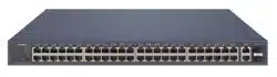
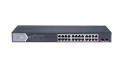
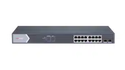
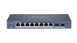
This manual is applicable to smart managed switches.
Symbol Convenons
The symbols that may be found in this document are dened as
follows.
Symbol Descripon
Danger
Indicates a hazardous situaon which, if not avoided,
will or could result in death or serious injury.
Cauon
Indicates a potenally hazardous situaon which, if
not avoided, could result in equipment damage, data
loss, performance degradaon, or unexpected
results.
Note
Provides addional informaon to emphasize or
supplement important points of the main text.
iii

Contents
1 Product Introducon ................................................ 1
2 Device Management ................................................. 1
2.1 Acvate Device ..................................................... 1
2.2 Add Device ............................................................ 2
3 Device Status ............................................................ 4
4 Topology Management ............................................. 5
4.1 Related
Operaons ............................................... 5
4.2 Topology
Sengs .................................................. 6
iv

1 Product Introducon
The switches support management through the iVMS-4200 client,
including network topology management, network conguraon,
port management, etc.
Note
All pictures in this manual are only for illustraon, and the
specic interfaces are subject to the actual device.
2 Device Management
You can perform device conguraon and management on the
iVMS-4200 client, mainly including network parameter
conguraon, port conguraon, network topology
management, etc.
Note
This chapter will briey introduce device management via
iVMS-4200 client. For other funcons, please refer to iVMS-4200
Client User Manual.
2.1 Acvate Device
For an inacve device, you are required to create a password to
acvate it before it can be added to the client and work properly.
Before You Start
Make sure that the device to be acvated is connected to the
network and is in the same network segment with the PC running
the client.
Steps
Note
This funcon should be supported by the device.
1. Click Maintenance and Management → Device Management
→ Device .
2. Click Online Device.
The searched online devices are displayed in the online device
list below.
3. Check the device status (shown in the Security Level column),
and select an
inacve device.
Figure 2-1 Online Device List
4. Click Acvate.
1

Figure 2-2 Acvate Device
5. Create a password in the password eld, and conrm the
password.
Note
●
The password strength of the device can be automacally
checked. We highly recommend you change the password of
your own choosing (using a minimum of 8 characters,
including at least three kinds of the following categories:
uppercase leers, lowercase leers, digits, and special
characters) in order to increase the security of your product.
And we recommend you change your password regularly,
especially in the high security system. Changing the
password monthly or weekly can
beer protect your
product.
●
The password cannot contain "admin" or its reverse.
●
Proper
conguraon of all passwords and other security
sengs is the responsibility of the installer and/or end-user.
6. Oponal: Check Enable Hik-Connect if the device supports Hik-
Connect service.
7. Click OK.
Note
Aer the device is acvated, you can click or in the
Operaon column of the online device list to modify network
parameters or reset the password of the device.
2.2 Add Device
Aer the device is acvated, you can add it to the client in OTAP
mode for remote conguraon and management.
Before You Start
Obtain the IP address, user name, and password of the device to
be added.
Steps
1. Click Device Management → Device.
2. Click Add.
2
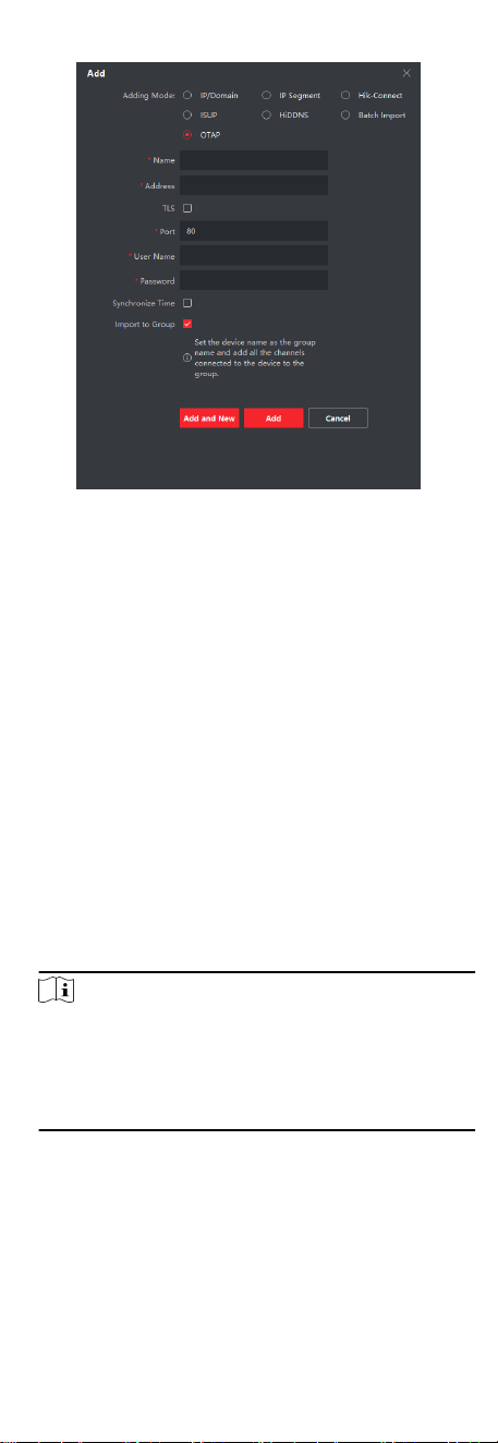
Figure 2-3 Add Device
3. Select OTAP as Adding Mode.
4. Enter the required
informaon.
Name
Enter a descripve name for the device.
IP Address
Enter the IP address of the device.
Port
Set the port number of the device. The default port number
is 80.
User Name
Enter the user name set when the device is
acvated. By
default, the user name is admin.
Password
Enter the password set when the device is acvated.
5. Oponal: Check TLS to enable transmission encrypon using
TLS (Transport Layer Security) protocol for security purposes.
Note
●
This funcon should be supported by the device.
●
The client does not support security cercate
authencaon. Imporng a trusted device cercate is not
required. You only need to set Enhanced SDK Service Port
(443 by default) to enable transmission
encrypon.
6. Check Synchronize Time to synchronize the device me with
the PC running the client.
7. Oponal: Check Import to Group to create a group by device
name, and import all channels of the device to this group.
8. Click Add to
nish device adding, or click Add and New to
connue adding another device.
3
9. Oponal: Perform the following operaons.
Perform
Remote
Conguraon
Click in the Operaon column for
remote conguraon of the
corresponding device.
View Device
Status
Click in the Operaon column to view
the device status.
Edit Device
Informaon
Click in the Operaon column to edit
the device informaon, including the
device name, IP address, pot number,
user name, and password.
Refresh
Click in the Operaon column or click
to get the latest device informaon.
Delete Device Select one or mulple devices, and click
to delete the selected device(s)
from the client.
View Alarm
Events
The device reports an alarm event when
the device is oine, the port is
disconnected, PoE is powered o, or the
whole device PoE power reaches or
exceeds the upper limit. You can click the
corresponding buon in the lower right
corner of the interface to
automacally
hide, lock, maximize, or manually hide
the alarm event list. The client supports
viewing device alarm event
informaon
and batch processing alarm events.
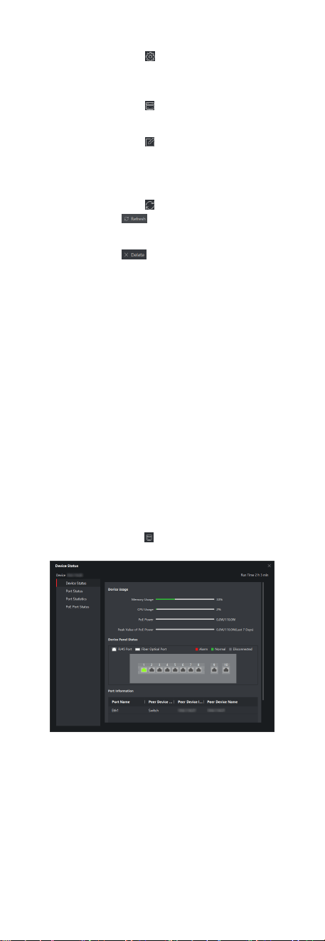
3 Device Status
You can view the device status, port status, port stascs, and
PoE port status.
Click Device →
Operaon → .
Figure 3-1 Device Status
Device Status
You can view the device usage, device panel status, and port
informaon.
Port Status
4

You can view the rate, duplex mode, and ow control enabling
status of each port.
Port Stascs
You can view the number of bytes sent or received, the
number of packets sent or received, sending or receiving rate,
and peak value of the sending or receiving rate (in the last
seven days). You can also set the interval at which port
stascs are automacally refreshed, manually refresh port
stascs, or clear port stascs.
Note
You can drag the scroll bar to view all stascs.
PoE Port Status
For devices that support PoE, you can view the PoE enabling
status and output power of each PoE RJ45 port.
4 Topology Management
You can view and congure the network topology between
devices added to the client.
4.1 Related Operaons
Select an added device, and click → General Applicaon →
Topology .
Figure 4-1 Topology Management
Interface Descripon
●
In the upper le corner, you can enter a device name or IP
address to search the desired device.
●
In the upper right corner, you can obtain the meanings of
dierent link icons and colors, select two devices to show the
transmission path between them, and export or refresh the
topology view.
●
In the lower
le corner, you can enable security protecon
with one click, perform topology sengs, and view the ps.
●
In the lower right corner, you can click the icons or scroll your
mouse wheel to zoom in or out on the topology view.
Note
●
Before generang the topology, make sure that all devices have
been added to the client. If a device is added to the client for
5
the rst me, click Add Topology to generate the device's
network topology.
●
If no topology is displayed when you access the topology
interface for the
rst me, click to refresh the topology view
or get topology again.
Related Operaons
Operaon Descripon
Double-click a device to
view the device details.
You can view the basic device informaon
such as the device type, model, and IP
address as well as the device usage, panel
status, and port informaon.
Double-click a link to view
the link details.
You can view the transmission rates of the
link and the informaon about devices at
both ends of the link.
Right-click a device, and
select Device Status,
Event Handling, Remote
Conguraon, Edit Name,
or Set as Root Node from
the shortcut menu.
Device Status: You can jump to the Device
Status interface. For details, see Device
Status.
Event Handling: You can view the
informaon about alarm events such as the
event me, event source, and event details,
or clear events.
Remote Conguraon: You can jump to the
web page of the device for remote
conguraon. For detailed operaons, see
Smart Managed Switch Web User Manual.
Edit Name: You can customize the device
name.
Set as Root Node: You can set the device as
the root node on the topology view.
Click to export the
topology view.
You can select the saving path and format,
and export the topology view.
Note
The default format is PDF.
Click to show the
transmission path.
You can select a network camera (IPC) and
the current device to show the path of signal
transmission between them.
4.2 Topology Sengs
Steps
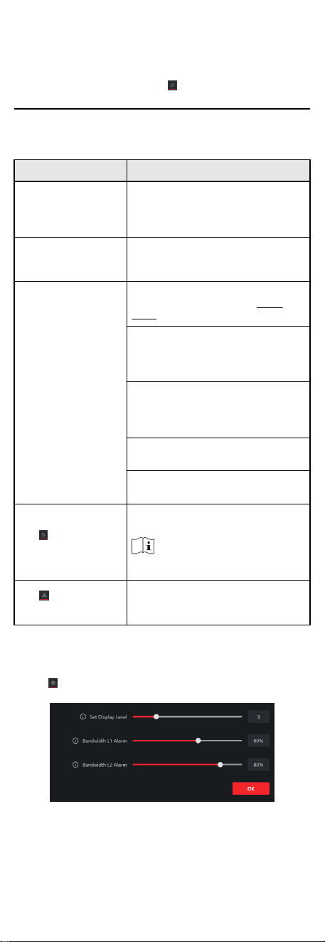
1.
Click in the lower le corner to edit topology sengs.
Figure 4-2 Topology Sengs
Set Display Level
6

Set the topology display level. The value ranges from 1 to 10.
Note
You need to manually refresh the topology view for the
seng to take eect.
Bandwidth L1 Alarm
Set the L1 alarm threshold of bandwidth. The value ranges
from 1% to 100%.
Note
The link will turn yellow (busy) when the bandwidth exceeds
this threshold.
Bandwidth L2 Alarm
Set the L2 alarm threshold of bandwidth. The value ranges
from 1% to 100%.
Note
●
The link will turn red (congested) when the bandwidth
exceeds this threshold.
●
The L2 alarm threshold should be larger than the L1 alarm
threshold.
2. Click OK.
Note
Aer topology sengs are changed, you can click to oban
the latest topology.
7