1
Español p. 15
Serial Number
PH1989
Purchase Date
ATTACH YOUR RECEIPT HERE
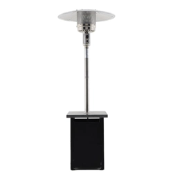
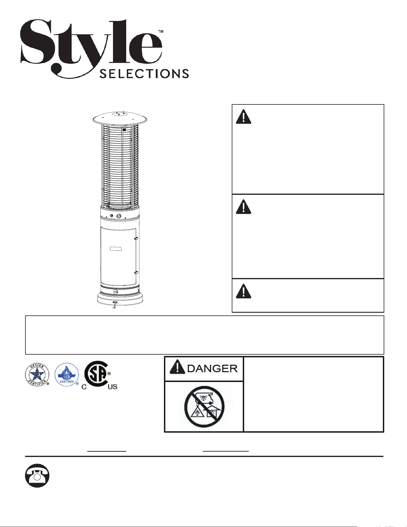
STEEL RAPID INDUCTION
OUTDOOR HEATER
ITEM # 1260941
MODEL # 51540
Questions, problems, missing parts? Before returning to your retailer, call our customer
service department at 1-800-643-0067, 8 am - 8 pm, EST, Monday - Friday.
DANGER
WARNING
WARNING
If you smell gas:
1. Shut off gas to the appliance.
2. Extinguish any open ame.
3. If odor continues, keep away from
the appliance and immediately call
your gas supplier or re
department.
Do not store or use gasoline or other
ammable vapors and liquids in the
vicinity of this or any other appliance.
An LP-cylinder not connected for use
shall not be stored in the vicinity of
this or any other appliance.
For outdoor use only.
Save these instructions for future use. If
you are assembling this unit for someone
else, give this manual to him or her to read
and save for the future.
Improper installation, adjustment, alteration, service or maintenance can cause injury or property
damage. Read the owner’s manual thoroughly before installing or servicing this equipment. If the
information in this manual is not followed exactly, a re or explosion may result causing property
damage, personal injury or loss of life.

2
• The installation of this unit must adhere to local codes or either the National Fuel Gas Code,
ANSI Z223. 1/NFPA54, OR CAN/CGA-B149.1, National Gas and Propane Installation Code.
• THIS UNIT IS INTENDED FOR OUTDOOR USE ONLY! This product shall be used outdoors, in a
ventilated space and shall not be used in any enclosed area.
• This unit is to be used with propane gas only! (sold separately)
• Do not attach a remote gas supply to this unit.
• Only use propane gas for this unit.
• This unit is not intended for natural gas.
• Converting this unit to natural gas is dangerous and not recommended. The conversion of this unit
will void the manufacturer warranty.
• If the propane gas tank is leaking gas, you may hear, see, or smell a hiss. Do the following:
1.Disconnectthepropanegastank.2.Donotattempttoxtheproblemyourself.3.Contactyour
gassupplierorredepartmentforhelp.
• Never install or remove a propane tank from this unit while it is in use.
• Applying too much propane may result in gas pooling and will not burn. Allow fresh air into the unit
so that the remaining gas may escape.
• Donotuseaametocheckforgasleaks.
• Themax.inletsupplypressure:max.Gassupply11inw.c.(2.74kPa)
• Use LP propane tanks with the following dimensions: 12-in diameter, 18-in height and 20-lb weight.
• You must use a propane tank that has a collar to protect the gas valve.
• DONOTlltankover80percentfull.
• The tank system must be set up for vapor withdrawal.
• Discontinue use if any part of the propane tank is damaged. Rust and dents may be hazardous
and should be inspected by a gas supplier.
• Do not operate unit until all parts are fully assembled.
• Do not paint or color any part of this heating unit.
• Unit may be hot while in use, do not attempt to move it while in use.
• Never leave this heating unit unattended while in use.
• This unit is not intended for cooking.
• Keepanyammableitemsaway.
• Keep a safe distance to avoid burning skin or clothing.
• Do not sit or rest hands or feet on this heating unit.
• Neverplacehandsorngersonupperportionofthisunitwhileinuse.
• Keep all electrical cords and fuel supply hose away from heated surfaces.
• Combustible materials should not be within 24 inches of the top of the unit, or within 24 inches
around the entire unit.
• Keeptheapplianceareaclearandfreefromcombustiblematerial,gasolineandotherammable
vapors and liquids.
• Never use the unit in spaces which may contain volatile or airborne combustibles.
• Iftheamegoesoutwhileburning,turnthegasvalveoff.Wait5minutesbeforerepeatingthe
initiallightingprocedure.Onceyouhaveaamestarted,holddownthecontrolknobfor1minute.
SAFETY INFORMATION
WARNING
Please read and understand this entire manual before attempting to assemble, operate or install
the product. Failure to follow the dangers, warnings and cautions contained in this owners manu-
almayresultinareorexplosioncausingdamagetoproperty,seriousbodilyinjuryordeath.

3
• Do not add water into the unit.
• Do not operate unit if any part has been under water. Call a service technician to replace any
damaged part should this occur.
• Do not disconnect any part while unit is in use.
• Do not store a spare propane tank on or near this unit.
• If the heating unit is indoors, detach the propane tank and leave outdoors.
• Donotoperateonaboatorvehicle.ThisunitmustbeusedonaatsurfaceandoutdoorsONLY.
• Always remove protective cover before operating (if applicable).
• Do not set the protective cover over the unit until it is turned off and completely cooled down.
• Check for leaks after not using the unit for long periods of time.
• Children should never operate this unit. Children must be supervised while near this unit.
• Keepgastankatleast5ftawayfromunitwhenlit.(ifexternaltank)
• Themaximumgassupplypressureis250psi.
• All installation and repair should be done by a qualied professional. This unit should be
inspected annually and cleaned regularly.
• Inspect all elements of this heating unit before each use. If there is damage, the burner must
be replaced.
• Be aware of the hazards of high temperatures and stay away from the unit to avoid any burns
orinjury.
• ThegassupplytankshouldbeconstructedandmarkedwiththespecicationsfortheLPgastanks
of the U.S. Department of Transportation or the National Standard of Canada CAN/CSA-B339, LP
gas tanks, spheres and tubes for Transportation of Dangerous Goods; and Commission.
• TheLPgastankmusthavealistedoverllingpreventiondeviceandaQCCIorTypeI,(CGA791)
LP gas tank connection.
• Thisheatingapplianceshouldnotbeusedonplasticorarticialwooddecks.
• Inspect the gas hose and all connections to the propane tank prior to each use.
• Always follow lighting instructions carefully.
• Do not use 30 lb. propane tanks for this unit.
• In case of high winds, secure this unit to the ground to prevent the unit falling over.
• Children and adults should be alerted to the hazards of high surface temperatures and
should stay away to avoid burns or clothing ignition.
• Clothing or other ammable materials should not be hung from the appliance or placed on
or near the appliance.
• Any guard or other protective device removed for servicing the appliance shall be replaced
prior to operating the appliance.
• Installation and repair should be done by a qualied service person. The appliance should
be inspected before use and at least annually by a qualied service person. More frequent
cleaning may be required as necessary. It is imperative that the control compartment,
burners and circulating airways of the appliance are kept clean.
Only use the regulator and hose assembly provided with this unit. Replacement parts must be
supplied directly by the manufacturer.
• Inspect the burner before use of this unit. If the burner shows any kind of damage, do not operate
the appliance. For assistance with repair or replacement of the burner or any other parts, call
our customer service department at 1-800-643-0067.
SAFETY INFORMATION
4
NOTE: You must follow all steps to properly assemble this heating item. Make sure the gas
valve is turned “OFF” before assembling. Do NOT attempt to assemble without proper tools.
SAFETY INFORMATION
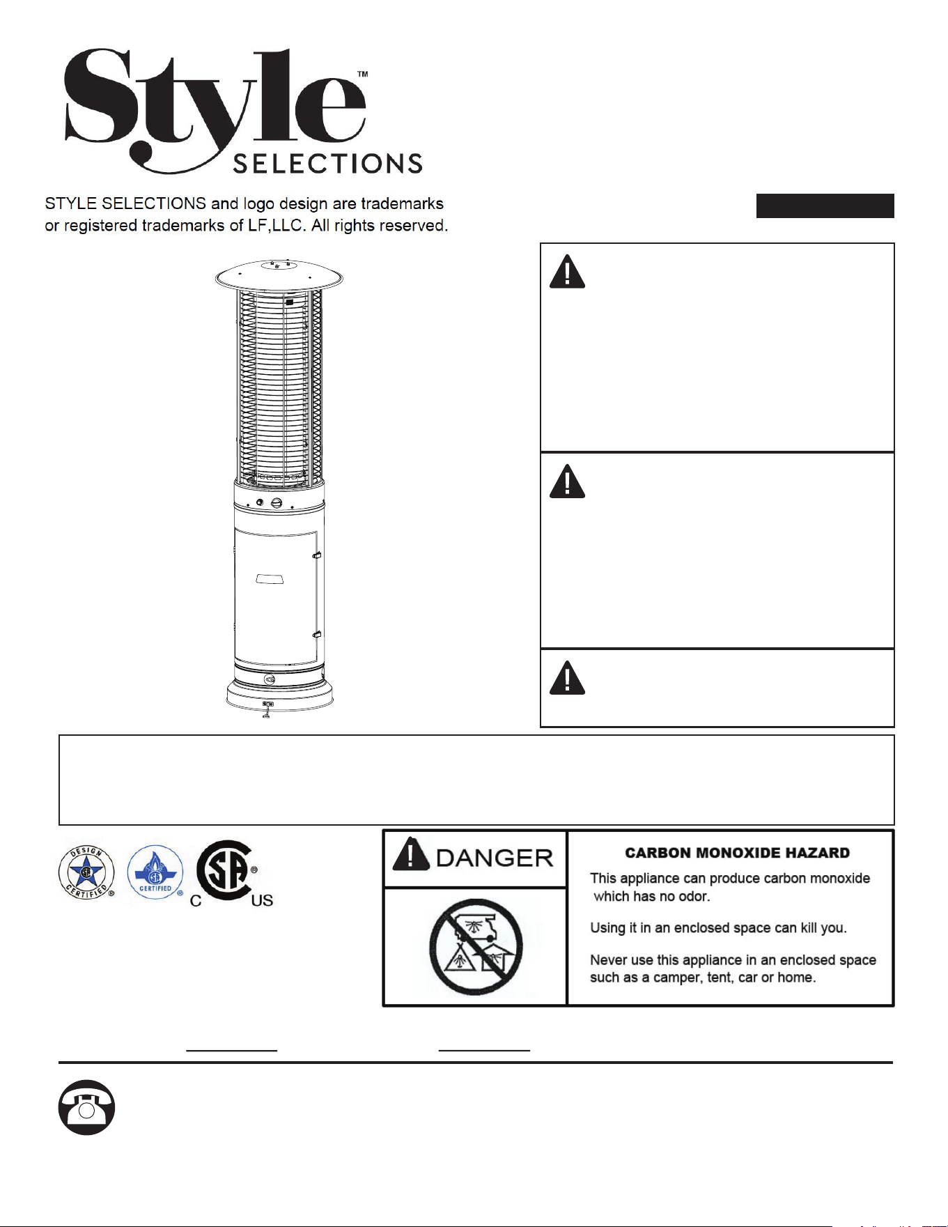
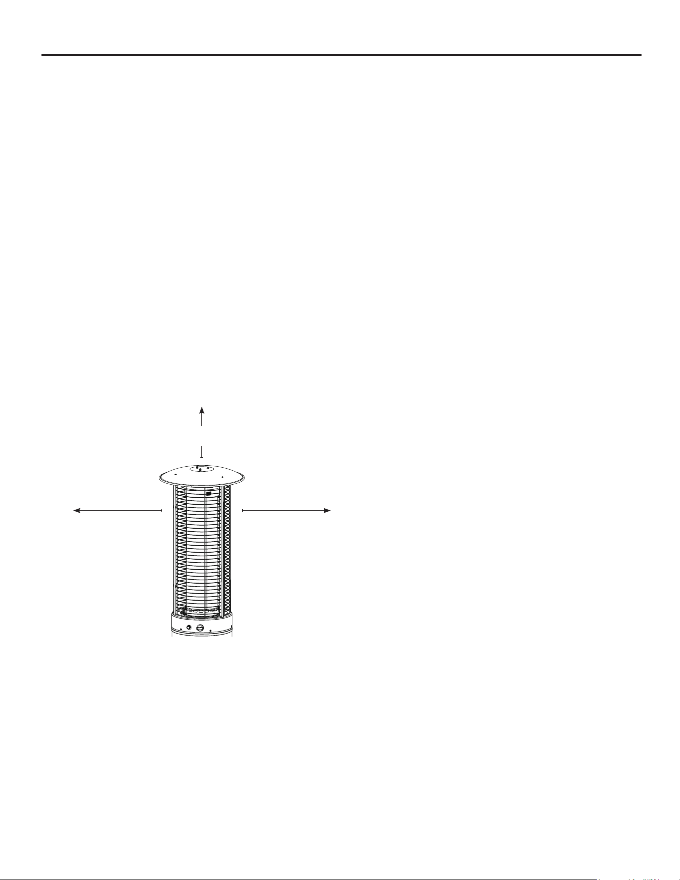
BE CAREFUL: WHEN CERTAIN
MATERIALS OR ITEMS ARE
STORED ABOVE, BESIDE OR
UNDER THIS HEATER WHILE IN
USE, THEY WILL BE SUBJECT TO
RADIANT HEAT AND COULD BE
SERIOUSLY DAMAGED.
Combustible materials should not
be within 24 inches of the top of the
unit, or within 24 inches around the
entire unit.
24 in.
60.96 cm
24 in.
60.96 cm
24 in.
60.96 cm
5
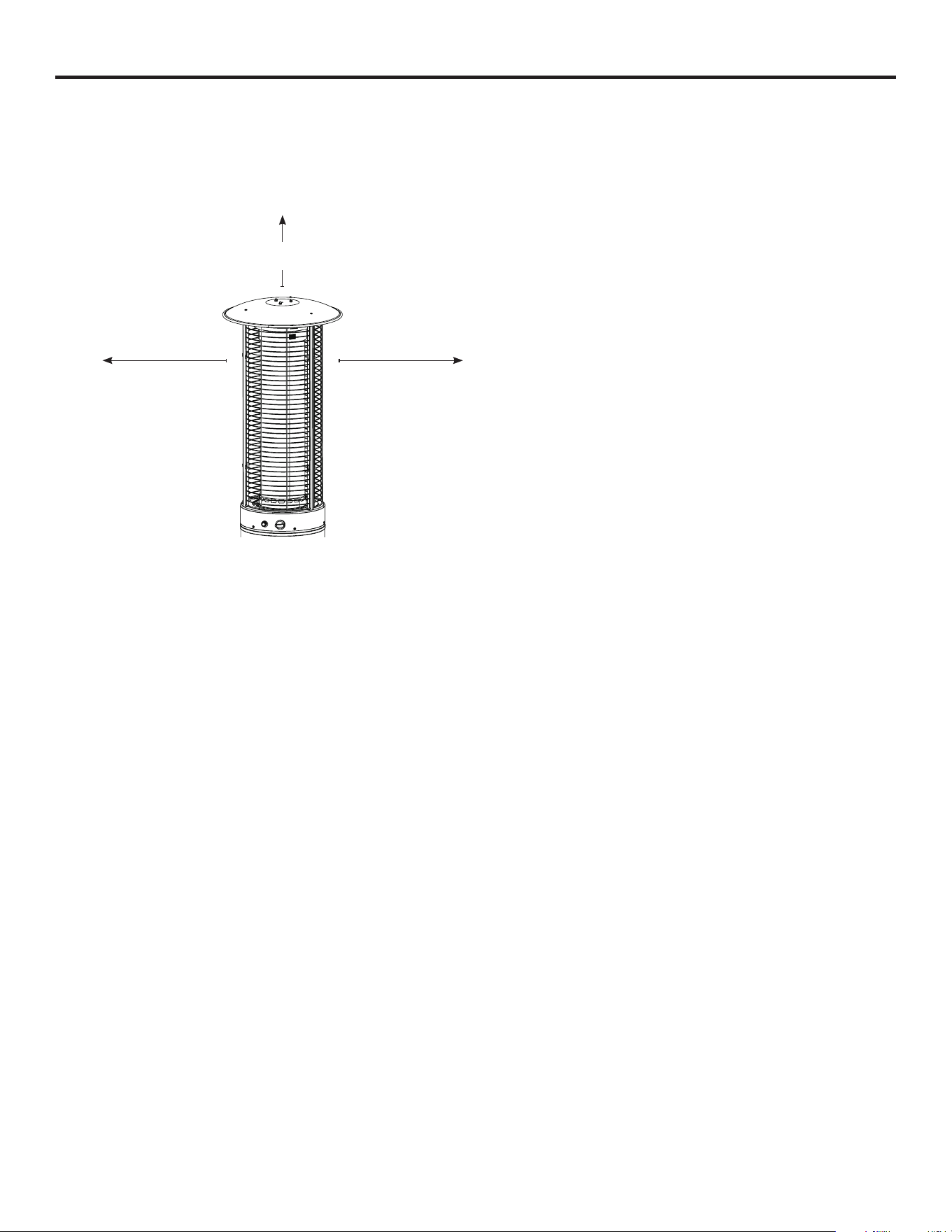
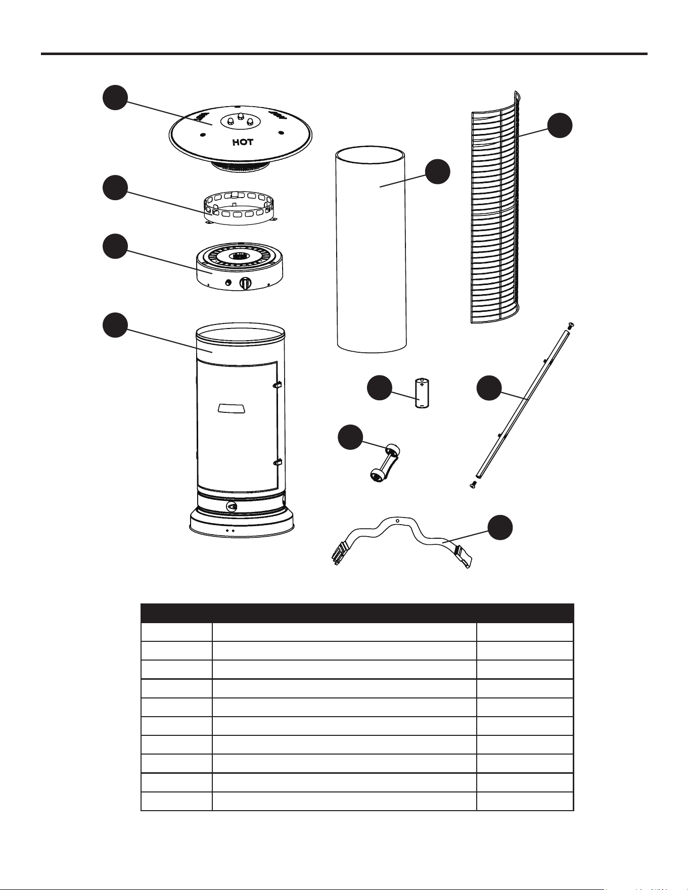
PACKAGE CONTENTS
PART DESCRIPTION QUANTITY
A UpperReector 1
B Glass Tube Ring 1
C Burner 1
D Tank Housing 1
E Glass Tube 1
F Mesh Guard 3
G Battery (AA) 1
H WheelAssembly 1
I Upper Supporter 3
J Belt 1
A
G
H
I
C
D
E
F
J
B

6
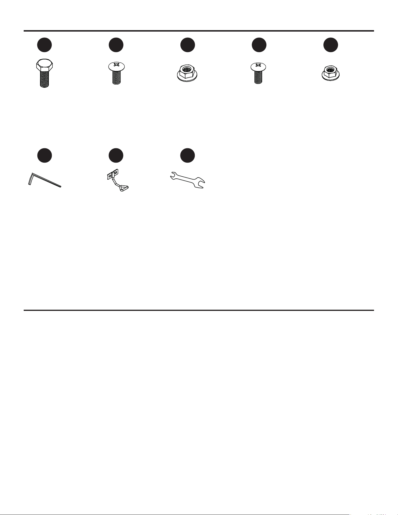
HARDWARE CONTENTS
AA
BB EE
M8x16
Screw
Qty.2
Anchor
Qty.3
Anchoring
Arm
Qty.3
Wrench
Qty.1
M5x12
Screw
Qty.5
M6x12
Screw
Qty.6
M6 Nut
Qty.6
M5 Nut
Qty.5
CC
FF
DD
GG HH
PREPARATION
Before beginning assembly of product, make sure all parts are present. Compare parts with
package contents list and hardware contents list. If any parts are missing or damaged, do not
attempt to assemble the product.
Estimated Assembly Time: 30 minutes
Tools Required for Assembly (not included): Phillips Screwdriver
NOTE: You must follow all steps to properly assemble the heating unit. Make sure the gas valve is
turned “OFF” before assembling. Do NOT attempt to assemble without proper tools.
7
ASSEMBLY INSTRUCTIONS
Hardware Used
Hardware Used
Hardware Used
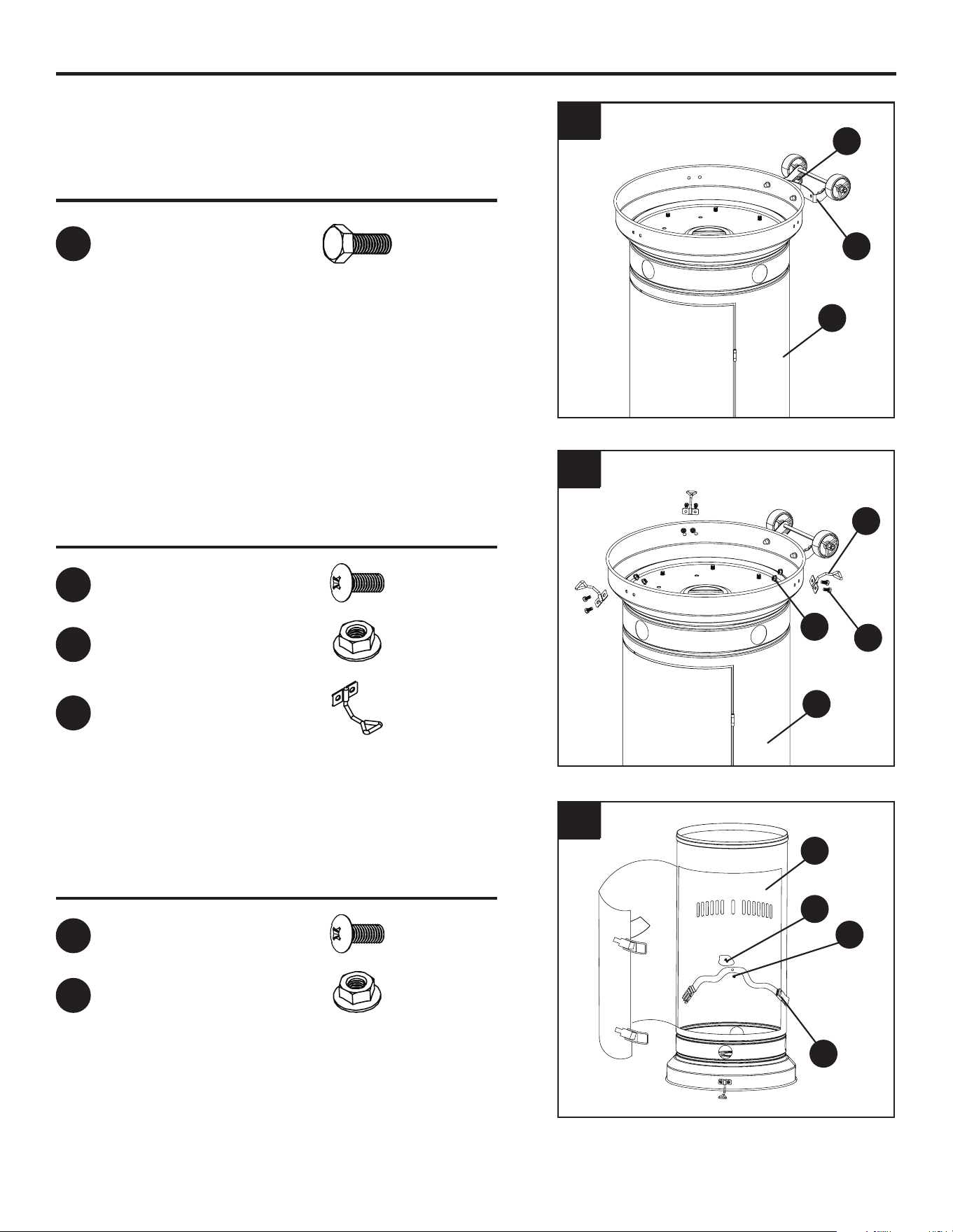
1. Turn the tank housing (D) upside down and attach
the wheel assembly (H) to the base of the tank
housing(D)using2M8x16screws(AA).
2. Attach the 3 anchoring arms (GG) onto the base
ofthetankhousing(D)using6M6x12screws(BB)
and 6 M6 nuts (CC).
3. Attach the belt (J) to the inside of the tank
housing using 1 M5X12 screw (DD) and 1 M5
nut (EE).
1
3
2
M8x16Screw
M6x12Screw
M5x12Screw
M6 Nut
M5 Nut
Anchoring Arm
x2
x6
x1
x6
x1
x3
AA
BB
DD
CC
EE
GG
AA
D
D
J
DD
EE
D
GG
H
CC
BB
8
ASSEMBLY INSTRUCTIONS
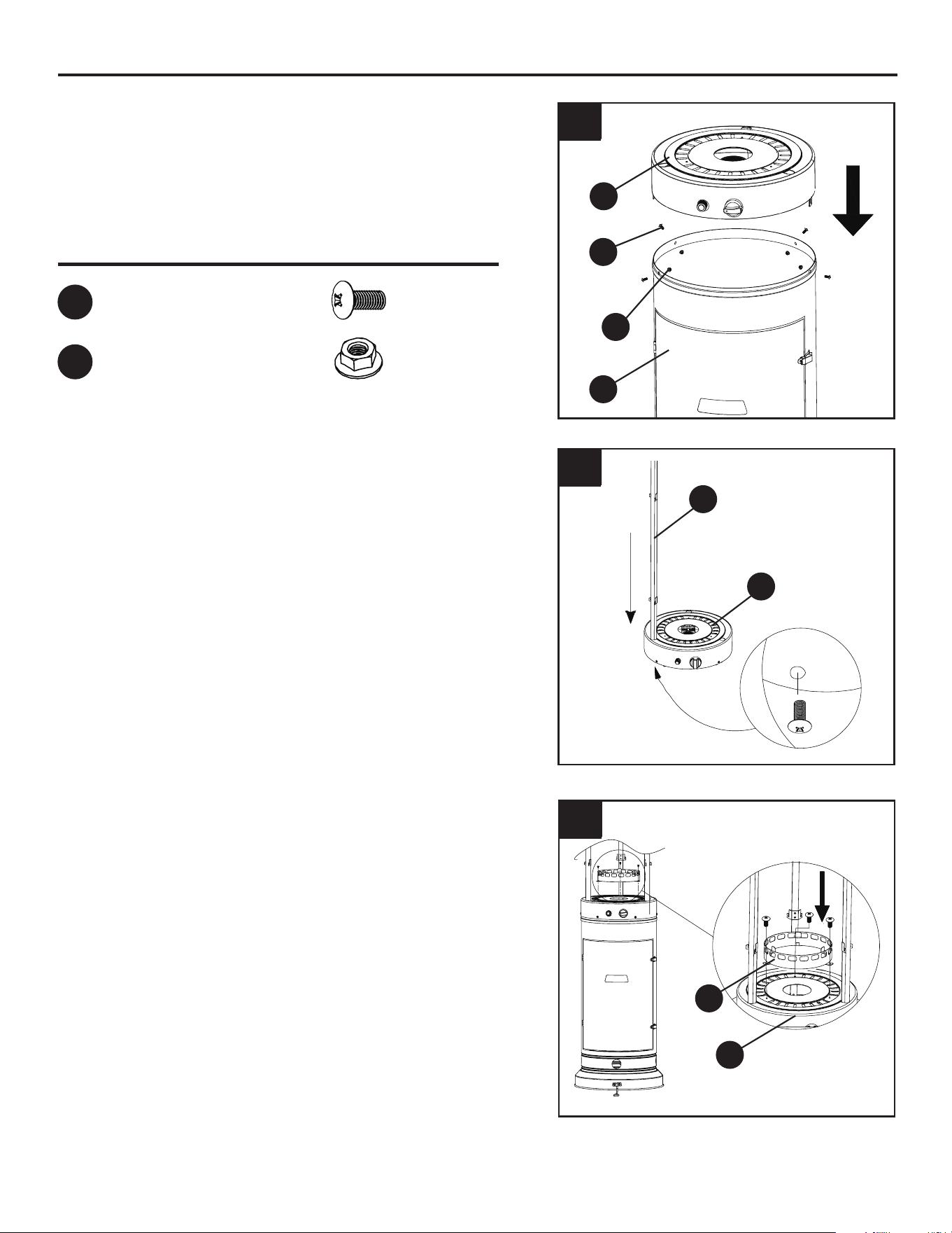
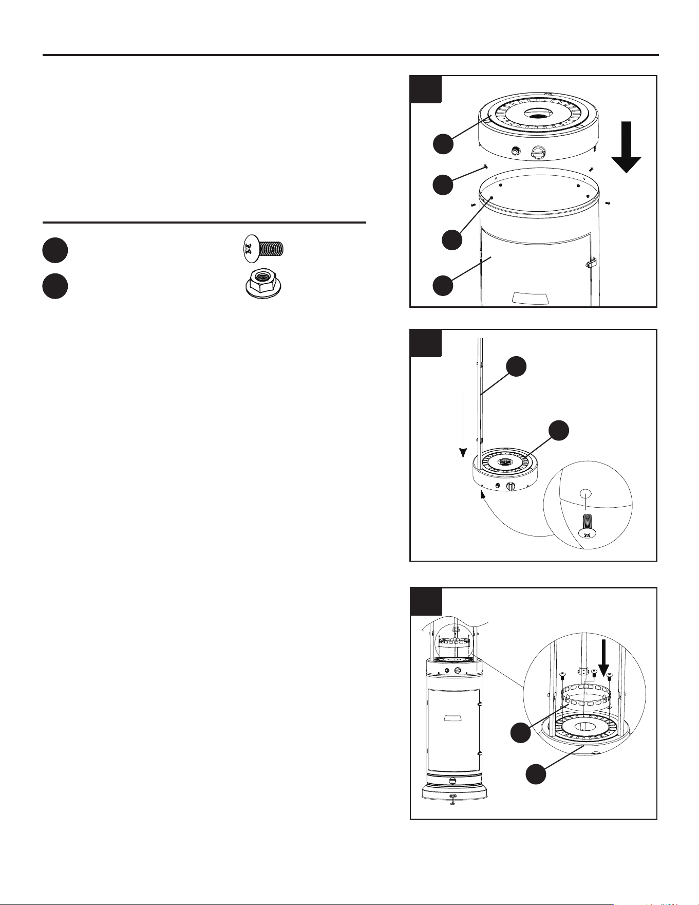
6. Remove the 3 preassembled screws from the top
of the burner (C). Attach the glass tube ring (B)
to the top of the burner (C) using the 3 screws
removed at the beginning of this step. Be sure to
fully tighten.
4. Align the holes at the bottom of the burner (C) to
the holes at the top of tank housing (D); ensure that
the control panel on the burner (C) is aligned with the
door on the tank housing (D). Attach the burner (C)
tothetopoftankhousing(D)using4M5x12screws
(DD) and 4 M5 nuts (EE). Be sure to fully tighten.
5. Remove the preassembled M5 screws from the
upper supporters (I). Slide the 3 upper supporters
into the slots at the top of the burner (C). Once
fully inserted, secure the upper supporters into
the burner by replacing the M5 screws that were
removed at the beginning of this step.
Note: Be sure that the hooks on the upper
supporters (I) are facing upwards.
4
5
6
DD
D
C
C
B
EE
Hardware Used
M5x12Screw
M5 Nut
x4
x4
DD
EE
I
C

9
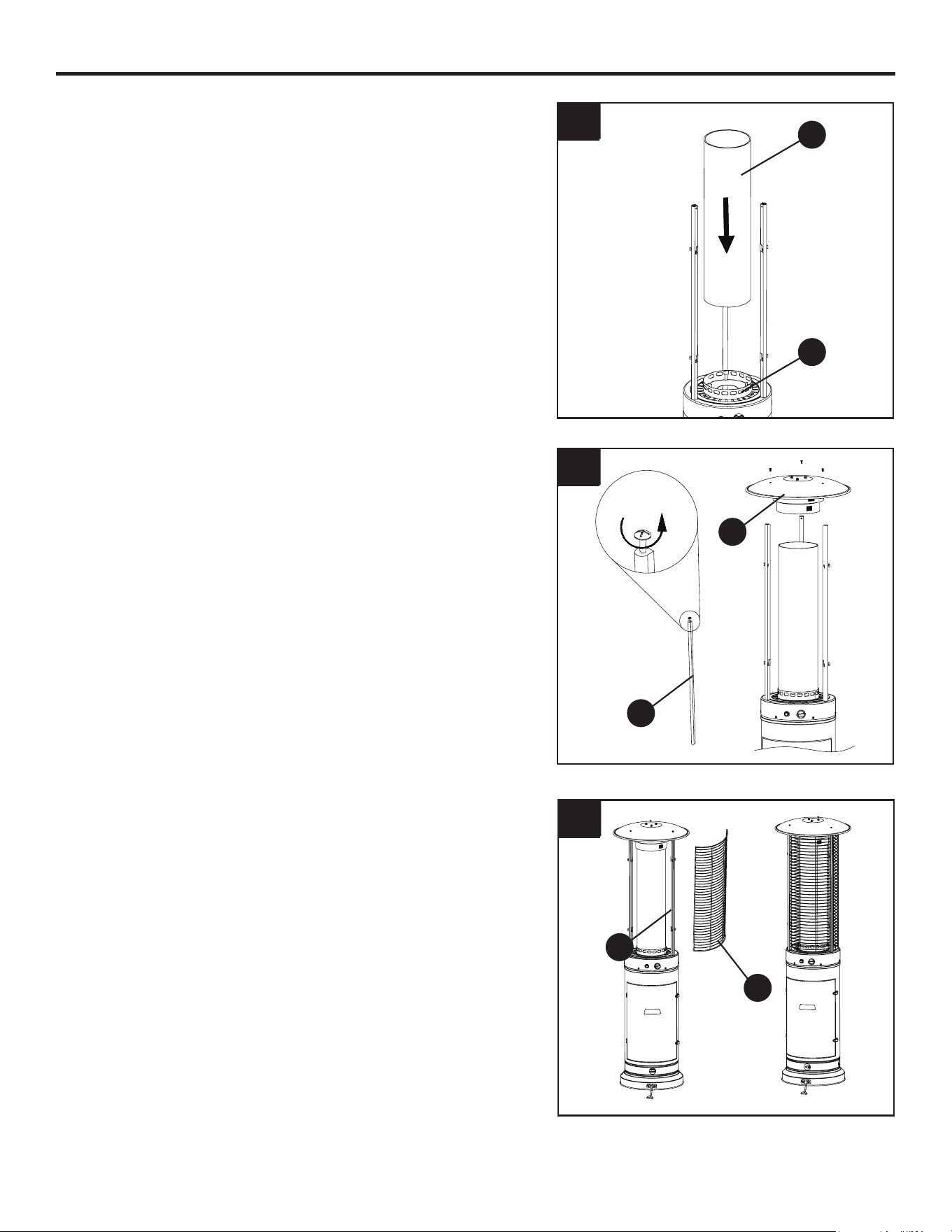
9. Attach the 3 mesh guards (F) onto the hooks at
the top of the upper supporters (I).
7. Place the glass tube (E) into the top of the glass
tube ring (B).
8. Remove the 3 preassembled screws from the
uppersupporters(I).Placetheupperreector(A)
onto the top of the upper supporters (I). Replace
the 3 screws removed at the beginning of this
steptosecuretheupperreector(A)totheupper
supporters (I). Be sure to fully tighten.
7
8
9
I
I
A
E
B
ASSEMBLY INSTRUCTIONS
F

10
ASSEMBLY INSTRUCTIONS
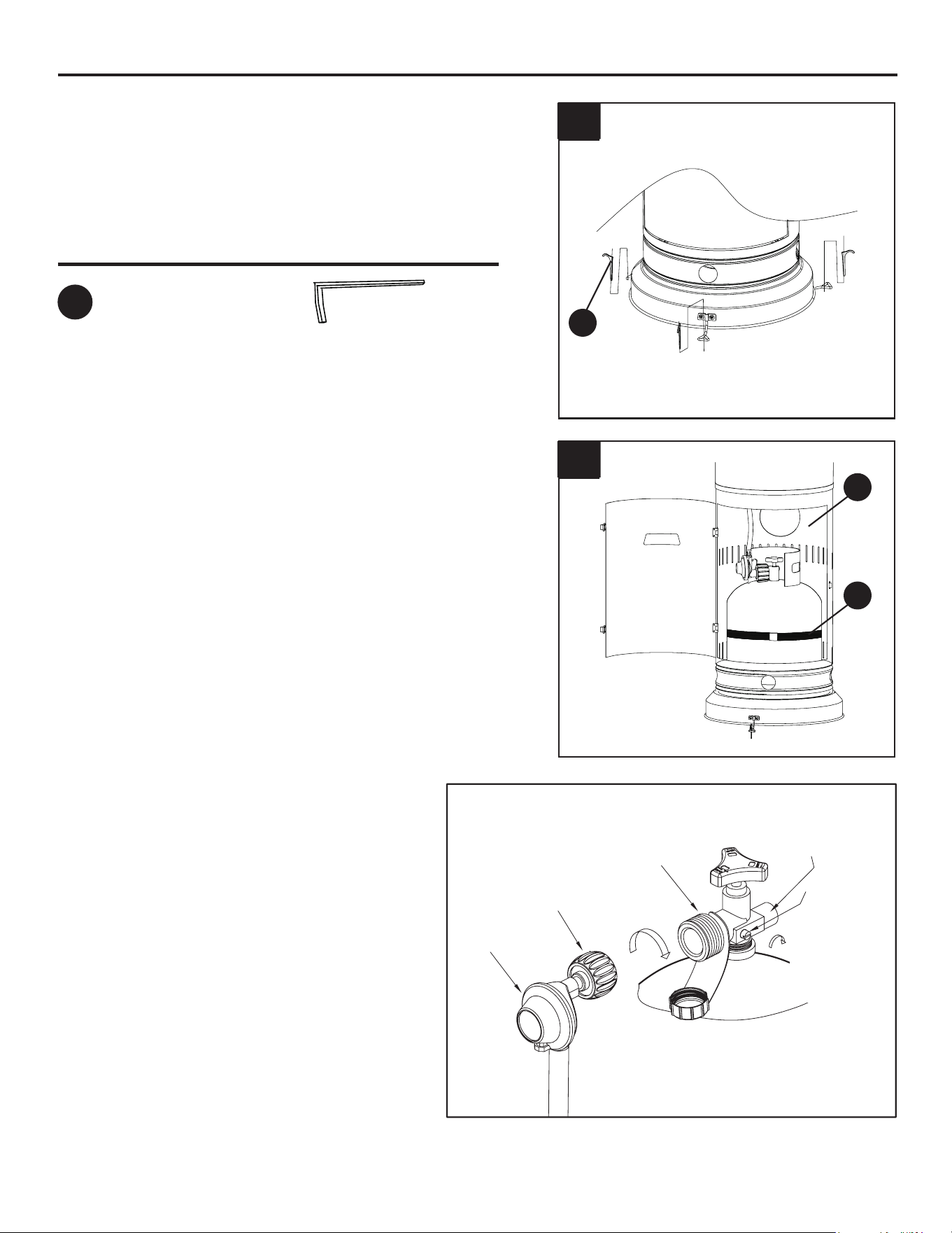
10. Optional: Use the anchor (FF) to fasten the
product into the ground.
11. Open the door from the tank housing (D) and
place the propane gas tank (not included) into the
preassembled tank supporter. Tighten the belt (J)
to ensure the propane gas tank is fully secure.
Note: Once the tank is connected to the regulator
inthenextstepbesuretoclosethedoorpriorto
use.
10
11
FF
Hardware Used
Anchor
x3
FF
J
D
CYLINDER VALVE
PRESSURE
RELIEF VALVE
BLEED-OFF
VALVE
BLACK COUPLING NUT
REGULATOR
turn clockwise to connect
turn clockwise
to reseal
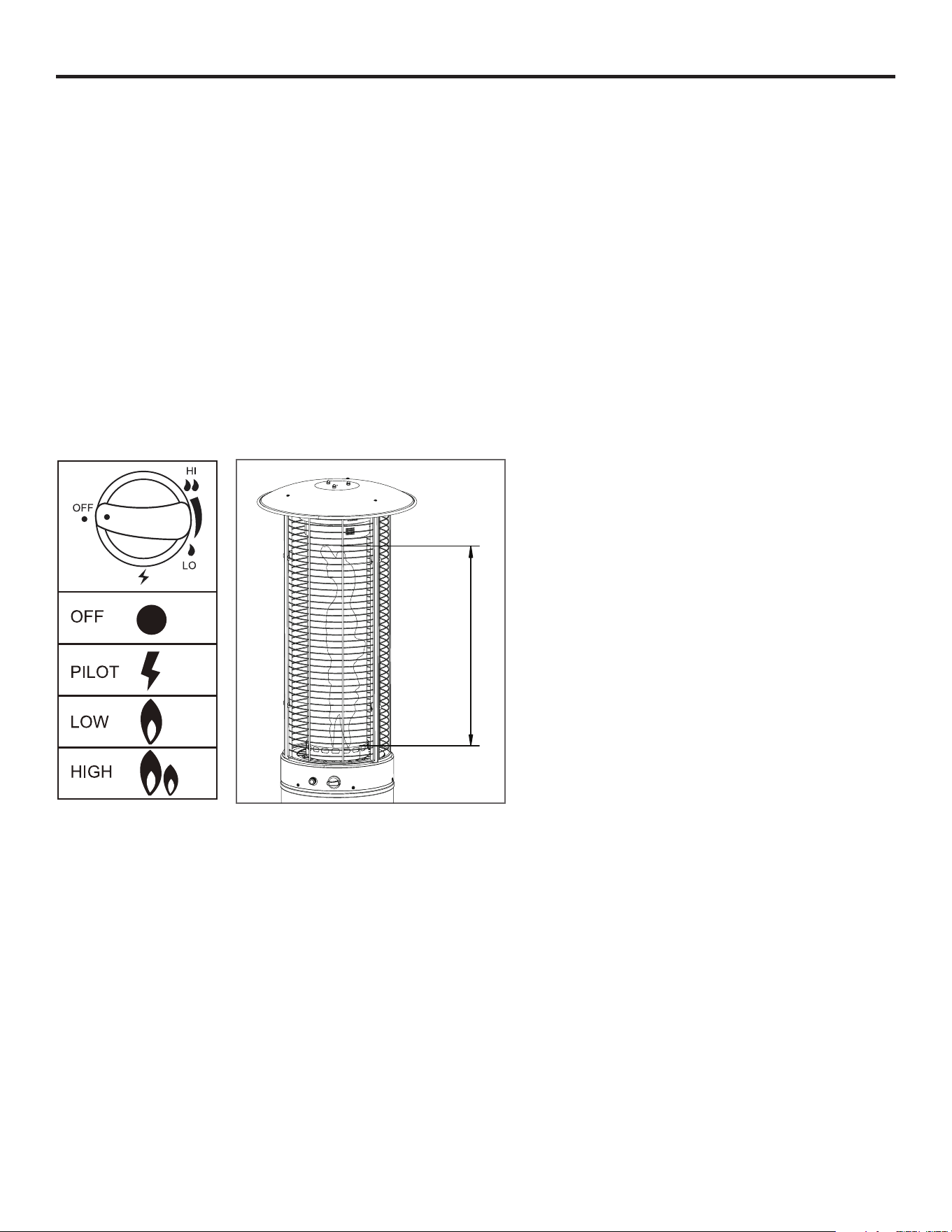
12. Turn the cylinder valve on the tank
clockwise to close the propane tank.
Attach the preassembled regulator to the
cylinder valve by turning the regulator
coupling nut clockwise. Make sure it is
fastened securely and tighten connections
by hand only.
11
OPERATING INSTRUCTIONS
Before performing a leak test, be sure that no sparks can occur and you are in a spacious outdoor
area. Connect the propane gas tank to the regulator and turn the valve on the unit to the “off” position.
Brushasoapandwatermixtureonallconnections.Turnthegassupplyon;ifbubblesoccuronany
connection there may be a leak. If you smell gas or a leak is discovered turn the gas valve off,
disconnect propane gas tank and do not use the appliance until the leak is is repaired.
• The glass tube may break if it is wet while in use; never use the heater while it’s raining outside.
• Do not splash any liquid on the heater while it is in use.
• Keepchildrenawayfromtheunitwhileinuse;theglasstubemaybeextremelyhotwhileinuse.
Do not touch.
• Ensurethattheheaterisonastrongandatsurface.Theheatermaybedamagediftheunit
tips over.
• Never use the heater if the glass tube shows any cracks.
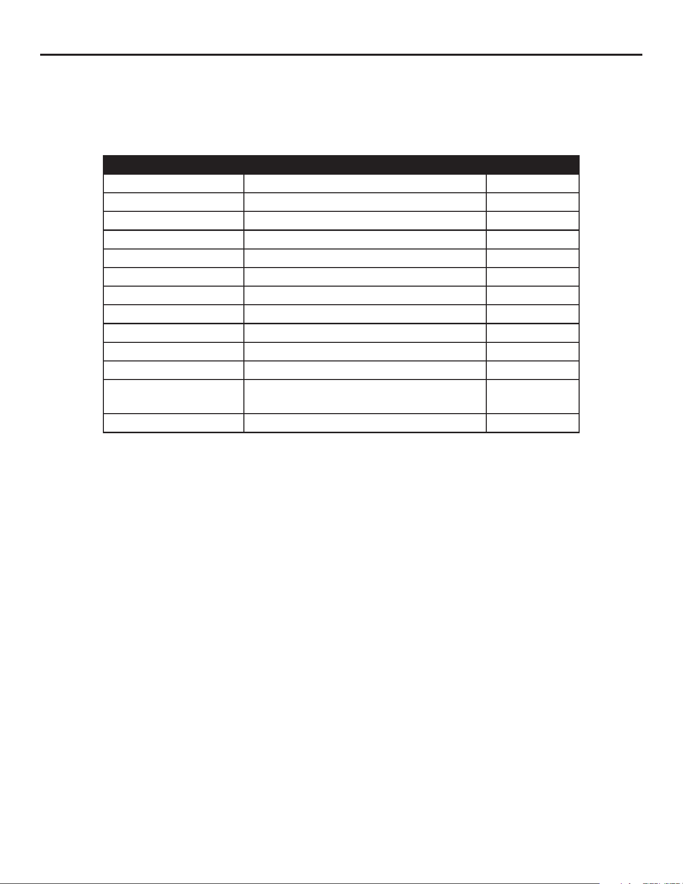
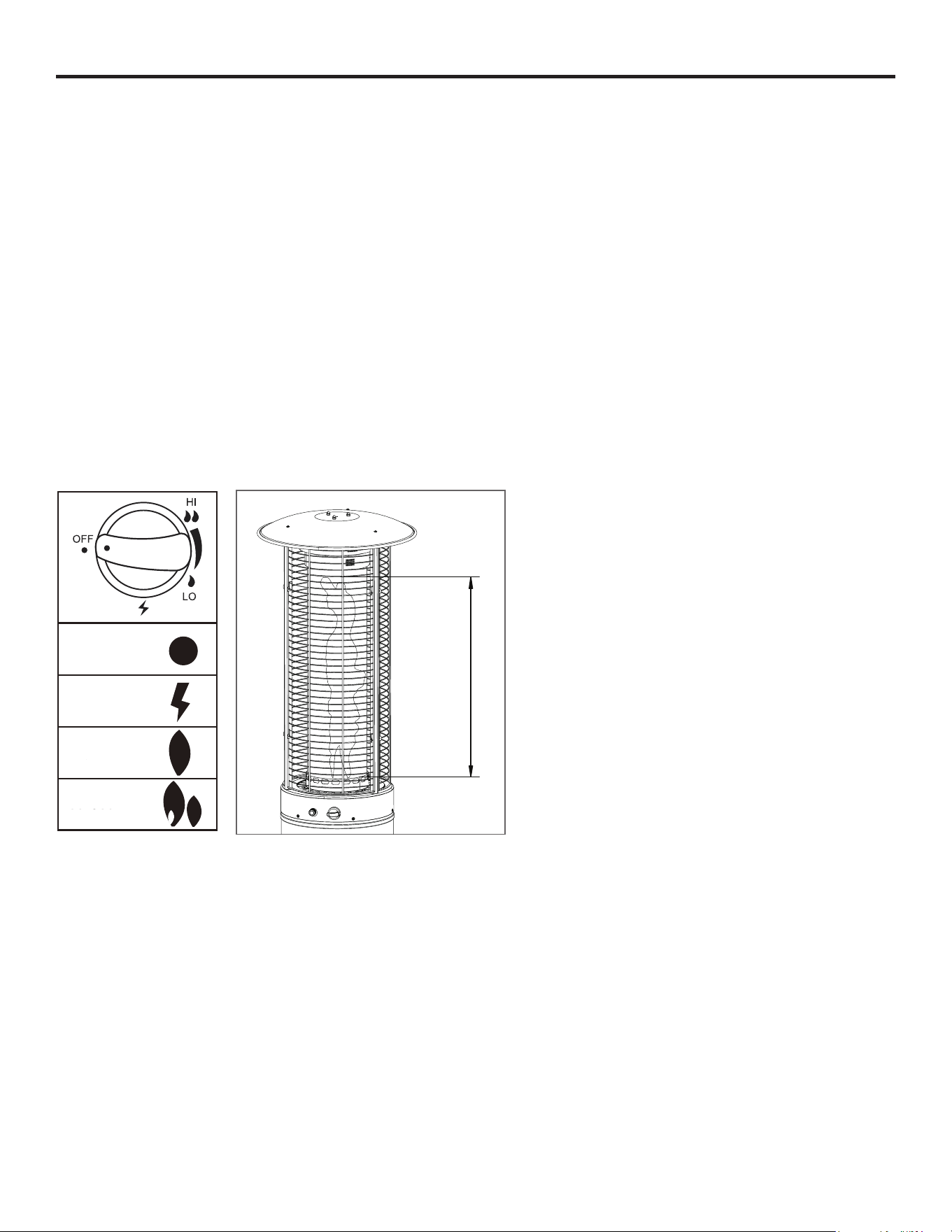
Observeameheightwhenlit.The
ameshouldbeayellow/bluecolor
between 20 - 28 inches in height.

12
WARRANTY
The manufacturer warranty will be voided by, and manufacturer disclaims any responsibility for, the
following actions:
• Modicationoftheunitand/orcomponentsincludingthegasvalveassembly.
• Use of any component part not manufactured or approved by manufacturer.
• Use and installation other than as instructed in this manual.
CARE AND MAINTENANCE
• Before performing any maintenance always disconnect propane gas tank.
• Keep the heating item free and clear from combustible materials.
• Visually inspect burner for obstructions and keep tank enclosure free and clear from debris.
• Use a soft brush to get rid of the mild stains, loose dirt and soil after the burner is completely cooled
down.Wipedownwithasoftcloth.
• Harsh weather conditions may cause stubborn stains, discoloration and possibly rust pitting.
• Permanent damage may occur if powder or solvent comes in contact with painted or plastic
components on this heating unit.
• Keep the heating unit stored away from direct sunlight.
• If storing this unit inside, disconnect the propane gas tank from the gas valve.
• Not using manufacturer approved or supplied parts/accessories may result in a defective condition
and void the warranty of this heating unit.
• Carbondepositsmayposeasarehazard;cleanthereectorandinsideoftheglasstubewith
soap and water if any carbon deposits are present.
OPERATING INSTRUCTIONS
1. Unscrew the ignition button on the burner to see if the battery (G) has already been placed inside.
If the battery (G) is not already within the ignition button on the burner, please place the battery (G)
into the ignition button slot.
2. Make sure the ignition control knob is turned to the “off” position. Connect propane gas tank and
slowly open the valve on the propane gas tank by turning the knob counterclockwise.
3. Press in and turn the ignition control knob to the “pilot” position; hold down for 1 minute.
4. Push the ignition button, while still holding down control knob down, to generate a spark.
5. Check to see if there is a pilot light through the glass tube (E). If there is, turn the control knob to
the “low” position.
6. Formaximumameheightandheatoutput,turnthecontrolknobtothe“high”position.
1. Push and turn the ignition control knob clockwise to the “off” position.
2. Turn the propane gas tank valve on the gas tank to close the gas supply and disconnect the
propane gas tank
To Light
WARNING: If the lighting instructions are not followed directly a re or explosion may occur
resulting in property damage, personal injury or death.
To Extinguish
13
Printed in China
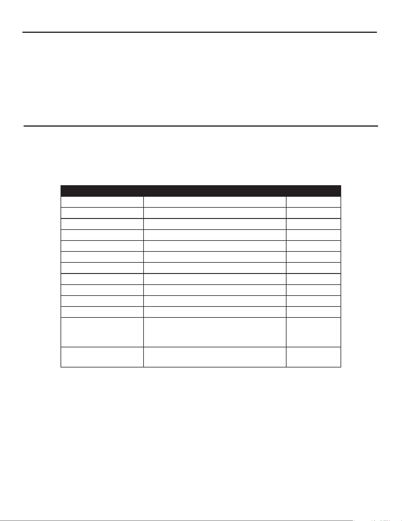
REPLACEMENT PARTS LIST
For replacement parts, call our customer service department at 1-800-643-0067, 8 am - 8 pm, EST,
Monday - Friday.
PART DESCRIPTION QUANTITY
Hardware Kit Hardware Kit 1
Part A UpperReectorAssembly 1
Part B Glass Tube Ring 1
Part C Burner Assembly 1
Part E Glass Tube 1
Part F Mesh Guard (3) 3
Part H Wheel 1
Part I Upper Supporter (3) 3
Part J Belt 1
Control Knob Control Knob 1
Pulse Ignition Pulse Ignition 1
Thermocouple
Bracket
Thermocouple Bracket (Include Ignition
Pin, Pilot Line & Thermocouple)
1
Gas Valve GasValveWithFittingsToBurner 1

14
15
Número de serie
Fecha de compra
ADJUNTE SU RECIBO AQUÍ
CALENTADOR PARA EXTERIORES
DE ACERO DE INDUCCIÓN RÁPIDA
ARTÍCULO #1260941
MODELO #51540
¿Preguntas, problemas, piezas faltantes? Antes de volver a la tienda, llame a nuestro
Departamento de Servicio al Cliente al 1-800-643-0067, de lunes a viernes de 8 a.m. a 8 p.m.,
hora estándar del Este.
PELIGRO
ADVERTENCIA
ADVERTENCIA
Si percibe olor a gas:
1. Cierre el suministro de gas hacia el
electrodoméstico.
2. Apague cualquier llama expuesta.
3. Si el olor persiste, manténgase
alejado del electrodoméstico y llame de
inmediato a su proveedor de gas o al
departamento de bomberos.
No almacene, ni use gasolina ni otros
vapores o líquidos inamables cerca de
este ni de ningún otro electrodoméstico.
No se deben almacenar cilindros de
gas PL que no estén conectados y en
uso cerca de este ni de ningún otro
electrodoméstico.
Solo para uso en exteriores.
Style SelectionsTM es una marca registrada de LF, LLC.
Todos los derechos reservados
Guarde estas instrucciones para uso
posterior. Si está ensamblando esta unidad
para otra persona, entréguele este manual
para que lo lea y lo conserve para referencia
futura.
La instalación, el ajuste, la alteración, la reparación o el mantenimiento inadecuados pueden producir
lesiones o daños a la propiedad. Lea detenidamente el manual del propietario antes de instalar o
reparar este equipo. Si no se sigue con precisión la información de este manual, pueden provocarse
incendios o explosiones que produzcan daños a la propiedad, lesiones personales o la muerte.
PELIGRO DE MONÓXIDO DE CARBONO
Este electrodoméstico puede producir
monóxidodecarbono,elcualesinodoro
Su uso en espacios cerrados puede ser fatal.
Nunca use este electrodoméstico en un
espacio cerrado, como dentro de tráilers,
carpas, automóviles o casas.

16
• La instalación de esta unidad debe cumplir con los códigos locales o con el Código Nacional de
Gas Combustible, ANSI Z223. 1/NFPA54, O CAN/CGA-B149.1, Código Nacional de Instalación de
Gas Natural y Propano.
• ¡ESTA UNIDAD ESTÁ DISEÑADA PARA USO EXCLUSIVO EN EXTERIORES! Este producto se
debe utilizar al aire libre, en un espacio ventilado y no se debe utilizar en ningún área cerrada.
• ¡Esta unidad se debe utilizar solo con gas propano! (se vende por separado)
• No conecte la unidad a un suministro de gas remoto.
• Use solo gas propano para esta unidad.
• Esta unidad no está diseñada para usarse con gas natural.
• La conversión de esta unidad a gas natural es peligrosa y no se recomienda hacerlo. La
conversión de esta unidad anulará la garantía del fabricante.
• Si el tanque de gas propano tiene una fuga de gas, es posible que lo vea, lo huela o escuche
un silbido. Haga lo siguiente: 1. Desconecte el tanque de gas propano. 2. No intente corregir usted
mismo el problema. 3. Póngase en contacto con su proveedor de gas o con el departamento de
bomberos para obtener ayuda.
• Nunca instale ni retire un tanque de propano de esta unidad mientras esté en uso.
• La aplicación de demasiado propano puede resultar en la acumulación de gas y no se quemará.
Dejequeentreairefrescoenlaunidadparaqueelgasrestantepuedaescapar.
• No utilice llamas para detectar fugas de gas.
• Presióndesuministrodeentradamáxima:suministromáximodegasde11pulg.decolumnade
agua (2,74 kPa)
• Utilice tanques de propano PL con las siguientes dimensiones: 30,48 cm de diámetro, 45,72 cm de
alto y 9,07 kg de peso.
• Debe usar un tanque de propano que cuenten con un anillo para proteger la válvula para gas.
• NO llene el tanque con más del 80 por ciento de su capacidad.
• Sedebeadaptarelsistemadeltanqueparalaextraccióndevapores
• Suspendaelusosialgunapartedeltanquedepropanoestádañada.Elóxidoylasabolladuras
pueden ser peligrosos y deben ser inspeccionados por un proveedor de gas.
• No opere la unidad hasta que todas las piezas estén completamente ensambladas.
• No pinte ni coloree ninguna pieza de esta unidad de calefacción.
• La unidad puede estar caliente mientras se usa, no intente moverla mientras está en uso.
• Nuncadejeestaunidaddecalentadorsinsupervisiónmientrasestéenuso.
• Esta unidad no está diseñada para cocinar.
• Mantengaalejadoslosartículosinamables
• Mantenga una distancia segura para evitar quemaduras en la piel o en la ropa.
• No se siente ni apoye las manos o los pies en esta unidad de calefacción.
• Nunca coloque las manos o los dedos en la parte superior de esta unidad mientras esté en uso.
• Mantengatodosloscableseléctricosylamangueradesuministrodecombustiblealejadosdelas
superciescalientes.
• Los materiales combustibles no deben estar a menos de 60,96 cm de la parte superior de la
unidad o a menos de 60,96 cm alrededor de toda la unidad.
INFORMACIÓN DE SEGURIDAD
ADVERTENCIA
Lea y comprenda completamente este manual antes de intentar ensamblar, usar o instalar
el producto. No seguir los avisos de peligro, las advertencias y las precauciones de este manual
delusuariopodríaprovocarincendiosoexplosionesquecausendañosalapropiedad,lesiones
personales graves o la muerte.

17
• Mantenga el área del electrodoméstico limpia y libre de materiales combustibles, gasolina y otros
vaporesolíquidosinamables
• Nunca use la unidad en espacios que puedan contener combustibles volátiles o transportados por
el aire.
• Si la llama se apaga durante el funcionamiento, cierre la válvula para gas. Espere 5 minutos antes
de repetir el procedimiento de encendido inicial. Una vez que haya encendido la llama, mantenga
presionada la perilla de control durante 1 minuto.
• No añada agua a la unidad
• No utilice la unidad si alguna de sus piezas estuvo sumergida en agua. Llame a un técnico de
servicio para que reemplace cualquier pieza dañada en caso de que esto ocurra.
• No desconecte ninguna pieza mientras la unidad esté en uso.
• No guarde un tanque de propano de repuesto en o cerca de esta unidad.
• Silaunidaddecalefacciónestáeninteriores,retireeltanquedepropanoydéjeloenelexterior.
• Noutiliceelproductoenunbarcoovehículo.EstaunidadsedebeusarSOLOenunasupercie
plana y al aire libre.
• Siempre retire la cubierta protectora antes del uso (si corresponde).
• No coloque la cubierta protectora sobre la unidad hasta que se haya apagado y enfriado por
completo.
• Revise si hay fugas si la unidad no se ha utilizado por periodos de tiempo prolongados
• Los niños nunca deben utilizar esta unidad. Los niños deben ser supervisados mientras
estén cerca de esta unidad.
• Mantenga el tanque de gas por lo menos a 1,52 m de distancia de la unidad cuando esté
encendida(sieltanqueesexterno).
• Lapresiónmáximadelsuministrodegasesde250psi.
• Solo un profesional calicado debe realizar la instalación y reparación del
electrodoméstico. Esta unidad se debe revisar anualmente y limpiar regularmente.
• Inspeccionetodosloselementosdeestaunidaddecalentamientoantesdecadauso.Siexiste
algún daño, se debe reemplazar el quemador.
• Seaconscientedelospeligrosdelasaltastemperaturasymanténgasealejadodelaunidadpara
evitar quemaduras o lesiones
• Lafabricaciónyelmarcadodeltanquedesuministrodegasdebecumplirconlasespecicaciones
para este tipo de tanques del Departamento de Transporte de EE. UU. o la Ley Nacional de Canadá
CAN/CSA-B339, tanques de gas PL, esferas y tubos para el Transporte de Mercancías Peligrosas; y
la Comisión.
• El tanque de gas PL debe estar equipado con un dispositivo de prevención de sobrellenado y una
conexiónparaeltanquedegasQCCIoTipo1(CGA791)homologado
• Este electrodoméstico de calefacción no se debe utilizar en cubiertas de plástico o de madera
articial
• Inspeccionelamangueradegasytodaslasconexionesaltanquedepropanoantesdecadauso.
• Siga siempre con atención las instrucciones de encendido.
• No use tanques de propano de 13,6 kg para esta unidad.
• En caso de fuertes vientos, asegure esta unidad al suelo para evitar que se caiga.
• Tanto niños como adultos deben estar informados sobre los peligros de las altas
temperaturas de la supercie y deben permanecer alejados para evitar quemaduras o que se
encienda la ropa.
• No se debe colgar ropa u otros materiales inamables del electrodoméstico ni colocarlos
• sobre o cerca del mismo.
INFORMACIÓN DE SEGURIDAD
18
INFORMACIÓN DE SEGURIDAD
• Se debe volver a colocar cualquier protector u otro dispositivo de protección que se haya
retirado para realizarle mantenimiento al electrodoméstico antes de hacerlo funcionar.
• Únicamente una persona de servicio calicada debe realizar la instalación y la reparación.
Una persona de servicio calicada debe inspeccionar el electrodoméstico antes de cada uso
y al menos una vez al año. Es posible que se requiera una limpieza más frecuente, según sea
necesario. Es esencial que mantenga limpios el compartimiento del control, los quemadores y
los conductos de circulación de aire del electrodoméstico
Use solamente el ensamble del regulador y la manguera incluidos con esta unidad. Las piezas de
repuesto las debe suministrar directamente el fabricante
Inspeccione el quemador antes de cada uso de esta unidad. Si el quemador presenta algún tipo de
daño, no haga funcionar el electrodoméstico. Para obtener ayuda con la reparación o el reemplazo
del quemador o de cualquier otra pieza, llame a nuestro Departamento de Servicio al Cliente al
1-800-643-0067.
NOTA: debe seguir todos los pasos para ensamblar adecuadamente este artículo de
calefacción. Asegúrese de que la válvula para gas esté “cerrada” antes del ensamblaje. NO
intente ensamblar sin las herramientas adecuadas
TENGA CUIDADO: SI CIERTOS
MATERIALES O ARTÍCULOS
SE ALMACENAN SOBRE ESTE
CALENTADOR O A SU LADO
MIENTRAS ESTÁ EN USO,
ESTARÁN SUJETOS A CALOR
RADIANTE Y SE PUEDEN DAÑAR
GRAVEMENTE.
Los materiales combustibles no
deben estar a menos de 60,96 cm
de la parte superior de la unidad o
a menos de 60,96 cm alrededor de
toda la unidad.
60,96 cm
(24 pulg.)
60,96 cm
(24 pulg.)
60,96 cm
(24 pulg.)
19
CONTENIDO DEL PAQUETE
PIEZA DESCRIPCIÓN CANTIDAD
A Reectorsuperior 1
B Anillo del tubo de vidrio 1
C Quemador 1
D Carcasa del tanque 1
E Tubo de vidrio 1
F Protector de malla 3
G Batería (AA) 1
H Ensamble de las ruedas 1
I Soporte superior 3
J Correa 1
A
G
H
I
C
D
E
F
J
B
20
ADITAMENTOS
AA
BB EE
M8x16
Tornillo
Cant. 2
Ancla de
expansión
Cant. 3
Brazo de
anclaje
Cant. 3
Llave inglesa
Cant. 1
M5x12
Tornillo
Cant. 5
M6x12
Tornillo
Cant. 6
Tuerca M6
Cant. 6
Tuerca M5
Cant. 5
CC
FF
DD
GG HH
PREPARACIÓN
Antes de comenzar a ensamblar el producto, asegúrese de tener todas las piezas. Compare las
piezas con la lista del contenido del paquete y la lista del contenido de aditamentos. No intente
ensamblar el producto si faltan piezas o si estas están dañadas.
Tiempo estimado de ensamblaje: 30 minutos
Herramientasnecesariasparaelensamblaje(noseincluyen):destornilladorPhillips
NOTA: debe seguir todos los pasos para ensamblar adecuadamente la unidad de calefacción.
Asegúresedequelaválvulaparagasesté“cerrada”antesdelensamblaje.NOintenteensamblar
sin las herramientas adecuadas.

21
INSTRUCCIONES DE ENSAMBLAJE
Aditamentos utilizados
Aditamentos utilizados
Aditamentos utilizados
1.Girelacarcasadeltanque(D)bocaabajoyjeel
ensamble de la rueda (H) a la base de la carcasa del
tanque(D)con2tornillosM8x16(AA).
2.Fijelos3brazosdeanclaje(GG)enlabasedela
carcasadeltanque(D)con6tornillosM6x12(BB)
y 6 tuercas M6 (CC).
3.Fijelacorrea(J)alinteriordelacarcasadel
tanque con 1 tornillo M5X12 (DD) y 1 tuerca
M5 (EE).
1
3
2
TornilloM8x16
TornilloM6x12
TornilloM5x12
Tuerca M6
Tuerca M5
Brazodeanclaje
x2
x6
x1
x6
x1
x3
AA
BB
DD
CC
EE
GG
AA
D
D
J
DD
EE
D
GG
H
CC
BB
22
6. Retire los 3 tornillos preensamblados de la parte
superiordelquemador(C).Fijeelanillodeltubode
vidrio (B) a la parte superior del quemador (C) con
los 3 tornillos que retiró al principio de este paso.
Asegúrese de apretar completamente.
4.Alineelosoriciosdelaparteinferiordel
quemador(C)conlosoriciosdelapartesuperior
de la carcasa del tanque (D); asegúrese de que el
panel de control del quemador (C) esté alineado
conlapuertadelacarcasadeltanque(D).Fijeel
quemador (C) a la parte superior de la carcasa del
tanque(D)con4tornillosM5x12(DD)y4tuercas
M5 (EE). Asegúrese de apretar completamente.
5. Retire los tornillos M5 preensamblados de los
soportes superiores (I). Deslice los 3 soportes
superiores en las ranuras de la parte superior del
quemador (C). Una vez que estén completamente
insertados, asegure los soportes superiores en el
quemador mediante la sustitución de los tornillos
M5 que se retiraron al principio de este paso.
Nota: asegúrese de que los ganchos de los
soportes superiores (I) estén orientados hacia
arriba.
4
5
6
DD
D
C
C
B
EE
Aditamentos utilizados
TornilloM5x12
Tuerca M5
x4
x4
DD
EE
I
C
INSTRUCCIONES DE ENSAMBLAJEINSTRUCCIONES DE ENSAMBLAJE
23
9.Fijelos3protectoresdemalla(F)enlosganchos
de la parte superior de los soportes superiores (I).
7. Coloque el tubo de vidrio (E) en la parte superior
del anillo del tubo de vidrio (B).
8. Retire los 3 tornillos preensamblados de los
soportessuperiores(I).Coloqueelreector
superior (A) en la parte superior de los soportes
superiores (I). Reemplace los 3 tornillos quitados
al principio de este paso para asegurar el
reectorsuperior(A)alossoportessuperiores(I).
Asegúrese de apretar completamente.
7
8
9
I
I
A
E
B
F
INSTRUCCIONES DE ENSAMBLAJE
24
10.Opcional:utiliceelancladeexpansión(FF)para
jarelproductoalsuelo.
11.Abralapuertadesdeelalojamientodeltanque
(D) y coloque el tanque de gas propano (no se
incluye) en el soporte del tanque preensamblado.
Apriete la correa (J) para garantizar que el tanque
de gas propano esté completamente seguro. Nota:
una vez que el tanque esté conectado al regulador
en el siguiente paso, asegúrese de cerrar la puerta
antes de usarlo.
10
11
FF
Aditamentos utilizados
Ancladeexpansión
x3
FF
J
D
VÁLVULA DEL
CILINDRO
VÁLVULA DE
DESCARGA DE
PRESIÓN
VÁLVULA
PARA
PURGAR
TUERCA DE
ACOPLAMIENTO
NEGRA, gire en
dirección de las
manecillas del reloj
para conectarla
REGULADOR
12. Gire la válvula del cilindro del tanque
endireccióndelasmanecillasdelreloj
para cerrar el tanque de propano. Gire el
acoplamiento de la tuerca en dirección de
lasmanecillasdelrelojparaconectarel
regulador previamente ensamblado a la
válvula del cilindro. Asegúrese de que esté
biensujetoyaprietelasconexionesconla
mano solamente.
INSTRUCCIONES DE ENSAMBLAJE
gire en
dirección de las
manecillas del
reloj para volver
a sellar
25
INSTRUCCIONES DE FUNCIONAMIENTO
Antes de realizar una prueba de fugas, asegúrese de que no se produzcan chispas y de que se
encuentreenunáreaexteriorespaciosa.Conecteeltanquedegaspropanoalreguladorygire
la válvula de la unidad a la posición de apagado. Aplique con una brocha una mezcla de agua y
jabónentodaslasconexiones.Enciendaelsuministrodegas;siseformanburbujasencualquier
conexión,puedehaberunafuga.Si huele a gas o se descubre una fuga, cierre la válvula para
gas, desconecte el tanque de gas propano y no utilice el electrodoméstico hasta que se
repare la fuga.
• Eltubodevidriopuederompersesiestámojadomientrasestáenuso;nuncauseelcalentador
mientras esté lloviendo afuera.
• No salpique ningún líquido sobre el calentador mientras esté en uso.
• Mantengaalosniñosalejadosdelaunidadmientraslausa;eltubodevidriopuedeestar
extremadamentecalientemientrasseusa.Nolotoque.
• Asegúresedequeelcalentadorestéenunasupercieresistenteyplana.Elcalentadorpuede
dañarse si la unidad se vuelca.
• Nunca utilice el calentador si el tubo de vidrio presenta grietas.
Observe la altura de la llama al
encender la unidad. Esta debe ser de
color azul/amarillo y debe medir entre
50,8 cm y 71,12 cm de alto (entre 20
pulg. y 28 pulg.).
APAGADO
PILOTO
BAJO
ALTO

26
CUIDADO Y MANTENIMIENTO
• Antes de realizar cualquier tarea de mantenimiento, desconecte siempre el tanque de gas propano.
• Mantengaelartículodecalefacciónlibreyalejadodematerialescombustibles.
• Inspeccione visualmente el quemador en busca de obstrucciones y mantenga el compartimiento
deltanquedespejadoylimpio.
• Una vez que el quemador se haya enfriado por completo, use un cepillo suave para eliminar las
manchas suaves, la suciedad suelta y la tierra. Limpie con un paño suave.
• Las condiciones climáticas adversas pueden causar manchas persistentes, decoloración y
posiblementepicadurasdeóxido
• Pueden producirse daños permanentes si el polvo o el disolvente entra en contacto con los
componentes pintados o de plástico de esta unidad de calentamiento.
• Mantengalaunidaddecalefacciónalmacenadalejosdelaluzsolardirecta.
• Si guarda esta unidad en interiores, desconecte el tanque de gas propano de la válvula para gas.
• No utilizar las piezas o los accesorios aprobados por el fabricante o suministrados, puede provocar
un estado defectuoso y anular la garantía de esta unidad de calefacción.
• Losdepósitosdecarbonopuedenrepresentarunriesgodeincendio;limpieelreectoryelinterior
deltubodevidrioconaguayjabónsihaydepósitosdecarbono.
INSTRUCCIONES DE FUNCIONAMIENTO
1. Desenrosque el botón de encendido del quemador para ver si la batería (G) ya está colocada en el
interior. Si la batería (G) no está de antemano dentro del botón de encendido del quemador, coloque
la batería (G) en la ranura del botón de encendido.
2. Asegúrese de que la perilla de control de encendido esté en la posición de apagado. Conecte el
tanque de gas propano y abra lentamente la válvula del tanque de gas propano mediante el giro de
laperillaendireccióncontrariaalasmanecillasdelreloj.
3. Presione y gire la perilla de control de encendido a la posición de “piloto”; manténgala presionada
durante 1 minuto.
4. Mientras mantiene presionada la perilla de control, presione el botón de encendido para generar
una chispa.
5. Compruebe si hay una luz del piloto a través del tubo de vidrio (E). Si la hay, gire la perilla de
controlhacialaposición“baja”.
6. Paraobtenerlamáximaalturadellamaypotenciadecalefacción,girelaperilladecontrolala
posición “alta”.
1. Presione la perilla de control de encendido y gírela a la posición de apagado.
2. Gire la válvula del tanque de gas propano del tanque de gas para cerrar el suministro de gas y
desconectarlo.
Para encender
ADVERTENCIA: si no se siguen directamente las instrucciones de iluminación, puede
producirse un incendio o una explosión que provoque daños materiales, lesiones personales
o la muerte.
Para apagar
27
GARANTÍA
La garantía del fabricante se anulará y el fabricante rechazará cualquier responsabilidad si se reali-
zan las siguientes acciones:
• Modicacióndelaunidadoloscomponentesincluidoelensambledelaválvulaparagas.
• El uso de piezas componentes no fabricadas ni aprobadas por el fabricante.
• Elusoylainstalacióndemaneradistintaalaespecicadaenestemanual.
LISTA DE PIEZAS DE REPUESTO
Para obtener piezas de repuesto, llame a nuestro Departamento de Servicio al Cliente al
1-800-643-0067, de lunes a viernes de 8 a.m. a 8 p.m., hora estándar del Este.
PIEZA DESCRIPCIÓN CANTIDAD
Kit de aditamentos Kit de aditamentos 1
Pieza A Ensambledelreectorsuperior 1
Pieza B Anillo del tubo de vidrio 1
Pieza C Ensamble del quemador 1
Pieza E Tubo de vidrio 1
Pieza F Protector de malla (3) 3
Pieza H Rueda 1
Pieza I Soporte superior (3) 3
Pieza J Correa 1
Perilla de control Perilla de control 1
Encendido de pulso Encendido de pulso 1
Abrazadera del
termopar
Abrazadera del termopar (incluye
pasador de encendido, línea de piloto y
termopar)
1
Válvula para gas Válvula para gas con conectores para
el quemador
1
Impreso en China