Loading ...
Loading ...
Loading ...
Target Mini Fixed Dome
3
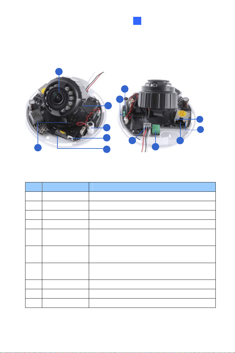
3.2.1 GV-EFD2700
1
3
2
5
d
a
b
6
c
9
4
7
8
Figure 3-2
No.
Name Description
1 Lens Receives image inputs.
2 Pan Screw Loosens the screw to adjust pan angle.
3 Tilt Screw Loosens the screw to adjust tilt angle.
4 Microphone Receives sound.
5 Default Button
Resets the camera to factory default. For details,
see 3.5 Loading Factory Default.
6
Memory Card
Slot
Inserts a micro SD card (SD/SDHC/UHSI,
Class 10) to store recording data.
7
I/O Terminal
Block
The connectors for the digital input and output.
For details, see 3.4.1 I/O Connector.
8 DC 12V Port Connects to power.
9 LAN / PoE Connects to a 10/100 Ethernet or PoE.
a Status Turns on (green) when the system is ready.
39
Loading ...
Loading ...
Loading ...