
Caution
Risk of explosion if battery is replaced by an incorrect type.
Dispose of used batteries according to the instructions.
Safety Notice
The GV-IPCAM uses a Lithium battery as the power supply for its internal
real-time clock (RTC). The battery should not be replaced unless required!
If the battery does need replacing, please observe the following:
• Danger of Explosion if battery is incorrectly replaced
• Replace only with the same or equivalent battery, as recommended by
the manufacturer
• Dispose of used batteries according to the manufacturer's instructions

© 2018 GeoVision, Inc. All rights reserved.
Under the copyright laws, this manual may not be copied, in whole or in
part, without the written consent of GeoVision.
Every effort has been made to ensure that the information in this manual is
accurate. GeoVision, Inc. makes no expressed or implied warranty of any
kind and assumes no responsibility for errors or omissions. No liability is
assumed for incidental or consequential damages arising from the use of
the information or products contained herein. Features and specifications
are subject to change without notice. Note: no memory card slot or local
storage function for Argentina.
GeoVision, Inc.
9F, No. 246, Sec. 1, Neihu Rd.,
Neihu District, Taipei, Taiwan
Tel: +886-2-8797-8377
Fax: +886-2-8797-8335
http://www.geovision.com.tw
Trademarks used in this manual: GeoVision, the GeoVision logo and GV
series products are trademarks of GeoVision, Inc.
July 2018

Contents
Options ..............................................................................iv
Creating GV-IP Camera’s Login Credentials..................vi
Note for USB Storage and WiFi Adapter .......................vii
Note for Installing Camera Outdoor............................. viii
Chapter 1 Mini Fixed Dome (Part I) & Mini Fixed
Rugged Dome.................................................................... 1
1.1 Packing List................................................................................4
1.2 Overview....................................................................................6
1.2.1 GV-MFD120 / 130 / 320................................................6
1.2.2 GV-MFD1501 Series / 2401 Series / 2501 Series / 3401
Series / 5301 Series................................................................8
1.2.3 GV-MDR ..................................................................... 10
1.3 Installation................................................................................ 13
1.3.1 GV-MFD Series........................................................... 13
1.3.2 GV-MDR Series ..........................................................15
1.4 Connecting the Camera...........................................................20
1.4.1 Wire Definition.............................................................20
1.4.2 Power and Network Connection .................................21
1.4.3 Vehicle Installation......................................................22
1.5 Loading Factory Default........................................................... 23
1.5.1 Using the Web Interface .............................................23
1.5.2 Directly on the Camera ...............................................24
Chapter 2 Mini Fixed Dome (Part II) ............................. 25
2.1 Packing List..............................................................................26
2.2 Overview..................................................................................27
i

2.3 Installation................................................................................ 29
2.4 Connecting the Camera...........................................................32
2.4.1 Wire Definition.............................................................32
2.4.2 Voltage Load Expansion (Optional) ............................33
2.5 Loading Factory Default........................................................... 34
2.5.1 Using the Web Interface .............................................34
2.5.2 Directly on the Camera ...............................................34
Chapter 3 Target Mini Fixed Dome............................... 35
3.1 Packing List..............................................................................36
3.2 Overview..................................................................................37
3.2.1 GV-EFD2700 .............................................................. 39
3.3 Installation................................................................................ 41
3.4 Connecting the Camera...........................................................44
3.4.1 I/O Connector..............................................................45
3.4.2 Voltage Load Expansion (Optional) ............................46
3.5 Loading Factory Default........................................................... 47
3.5.1 Using the Web Interface .............................................47
3.5.2 Directly on the Camera ...............................................47
Chapter 4 Target Mini Fixed Rugged Dome ................ 48
4.1 Packing List..............................................................................49
4.2 Overview..................................................................................51
4.2.1 GV-EDR2700 .............................................................. 52
4.3 Installation................................................................................ 53
4.4 Connecting the Camera...........................................................60
4.5 Loading Factory Default........................................................... 61
4.5.1 Using the Web Interface .............................................61
4.5.2 Directly on the Camera ............................................... 61
Chapter 5 Cube Camera ................................................ 63
5.1 Packing List..............................................................................64
5.2 Overview..................................................................................65
ii

5.3 Installation................................................................................ 66
5.4 Connecting the Camera...........................................................68
5.5 Loading Factory Default........................................................... 69
5.5.1 Using the Web Interface .............................................69
5.5.2 Directly on the Camera ............................................... 69
Chapter 6 Advanced Cube Camera.............................. 70
6.1 Packing List..............................................................................71
6.2 Overview..................................................................................72
6.3 Installation................................................................................ 74
6.4 Connecting the Camera...........................................................76
6.5 Loading Factory Default........................................................... 77
6.5.1 Using the Web Interface .............................................77
6.5.2 Directly on the Camera ............................................... 77
Chapter 7 Accessing the Camera................................. 78
7.1 System Requirement ............................................................... 78
7.2 Accessing the Live View .......................................................... 79
7.2.1 Checking the Dynamic IP Address .............................80
7.2.2 Configuring the IP Address ......................................... 82
7.2.3 Configuring the Wireless Connection..........................84
7.3 Adjusting Image Clarity............................................................ 87
Chapter 8 The Web Interface ........................................89
Chapter 9 Upgrading System Firmware ......................
92
iii
Options
Optional devices can expand your camera’s capabilities and versatility.
Contact your dealer for more information.
Device Description
Power Adapter
The power adapter is available for all Mini Fixed
Dome, Cube Camera, and Advanced Cube Camera.
Contact your sales representative for the countries
and areas supported.
GV-PA191 PoE
Adapter
The GV-PA191 PoE adapter is designed to provide
power and network connection to the cameras over
a single Ethernet cable.
GV-POE Switch
The GV-POE Switch is designed to provide power
along with network connection for IP devices. The
GV-POE Switch is available in various models with
different numbers and types of ports.
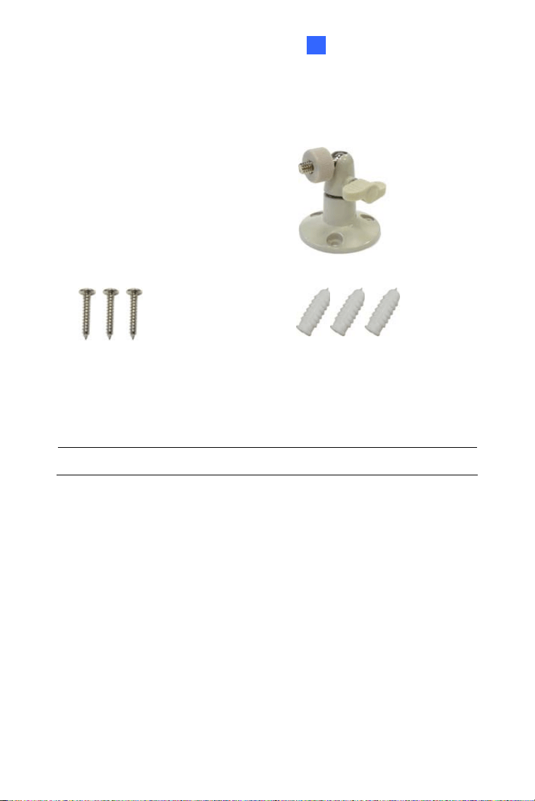
GV-Mount
Accessories
The GV-Mount Accessories provide a
comprehensive lineup of accessories for installation
on ceiling, wall corner and pole. For details, see GV-
Mount Accessories Installation Guide.
GV-WiFi Adapter
The GV-WiFi Adapter is a plug-and-play device
designed to connect the camera to wireless network.
The product complies with IEEE 802.11 b/g/n (Draft
3.0) standards for wireless networking.
Note: Only compatible models and firmware
versions support GV-WiFi Adapter
iv

Device Description
Plastic PG21
Conduit
Connector
The plastic PG21 conduit connector is used for
running the wires of Target Mini Fixed Rugged
Dome through a 1/2” conduit pipe.
The connector is not supported by GV-EFD2700 /
4700 Series and GV-MFD2700 / 4700 Series.
GV-Relay V2
The GV-Relay V2 is supported by GV-EFD2700
Series and GV-MFD2700 / 4700 Series. The GV-
Relay V2 is designed to expand the voltage load of
GV IP devices. It provides 4 relay outputs, and each
can be set as normally open (NO) or normally closed
(NC) independently as per your requirement.
v
Creating GV-IP Camera’s Login
Credentials
The default Administrator and Guest accounts are no longer supported by
firmware V1.14 or later. When purchasing a new camera or performing
factory resetting, you need to set up a login username and password for
the camera.
1. Download and install GV-IP Device Utility from the company
website.
2. On the GV-IP Device Utility window, click
to search for your GV-
IP camera.
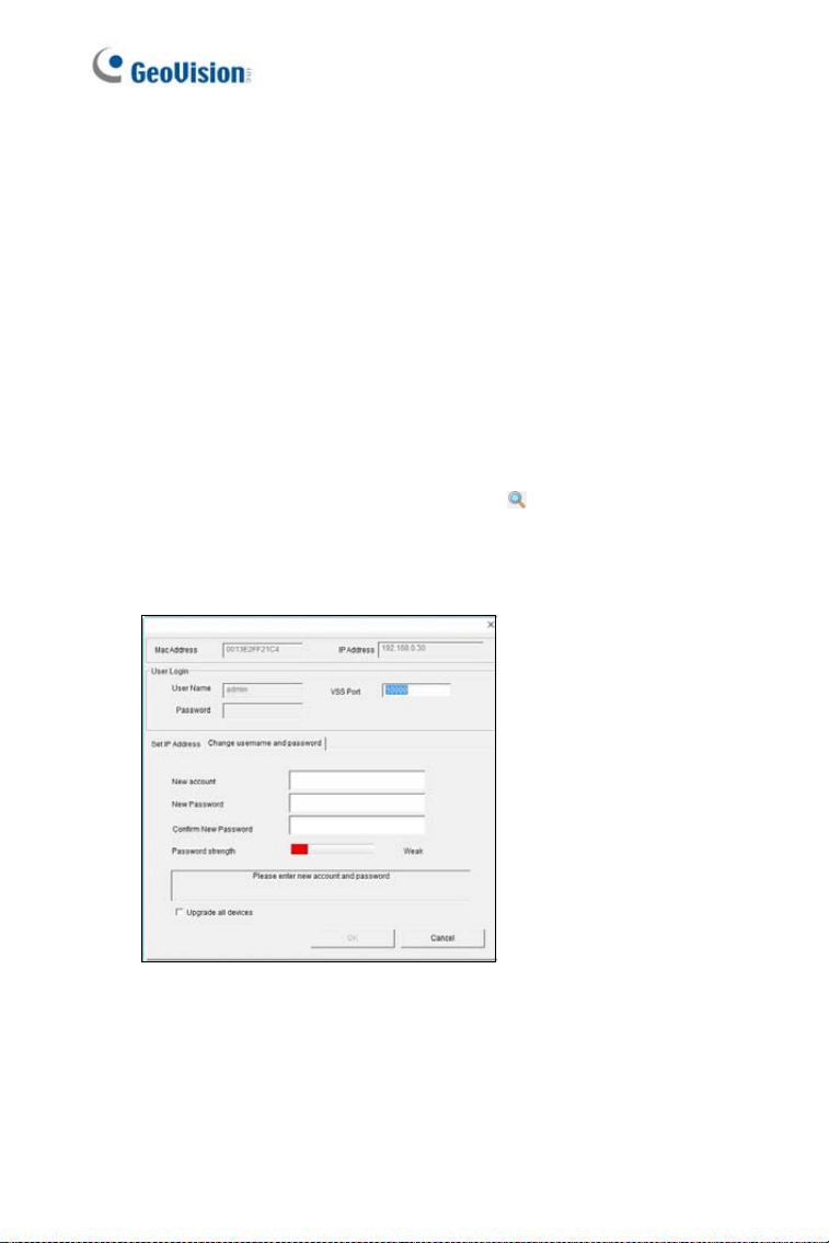
3. Double-click your GV-IP camera in the GV-IP Device Utility list. This
dialog box appears.
4. Click the Change Username and Password tab to type a new
username and password. Note that the new password must meet
the password strength requirements.
5. Optionally click Upgrade all devices to use the same username
and password on all other devices.
vi

Note for USB Storage and WiFi
Adapter
Mind the following limitations and requirements for using USB storage and
GV-WiFi Adapter:
1. The USB hard drive must be of 2.5’’ or 3.5’’, version 2.0 or above.
2. The USB hard drive’s storage capacity must not exceed 2TB.
3. USB flash drives and USB hubs are not supported.
4. External power supply is required for the USB hard drive.
5. To connect a GV-WiFi Adapter, make sure it is connected before the
camera is powered on.
vii
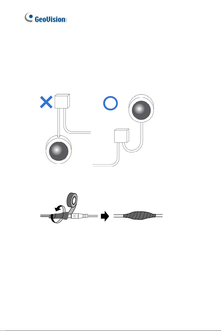
Note for Installing Camera Outdoor
When installing Mini Fixed Rugged Dome outdoor, be sure that:
1. The camera is set up above the junction box to prevent water from
entering the camera along the cables.
2. Any PoE, power, audio and I/O cables are waterproofed using
waterproof silicon rubber or the like.
3. The silica gel bag loses its effectiveness when the dry camera is
opened. To prevent the lens from fogging up, replace the silica gel bag
every time you open the camera, and conceal the gel bag in camera
within 2 minutes of exposing to open air.
viii

Mini Fixed & Rugged Dome
1
1
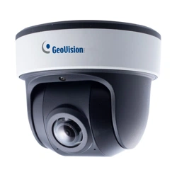
Chapter 1 Mini Fixed Dome (Part I)
& Mini Fixed Rugged Dome
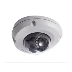
The Mini Fixed Dome (GV-MFD) and Mini Fixed Rugged Dome (GV-MDR)
are fixed, mini-sized ceiling-mount network cameras.
The GV-MDR series is designed for outdoor surveillance, conforming to
IK10 and IP67 standards. The camera is adjustable in 3 axis (pan, tilt and
rotate) and can be connected through PoE.
The GV-MFD series is designed for indoor surveillance. Adjustable in 2
axis (pan and tilt), the camera also supports PoE.
The super low lux models can provide color live view in near darkness
and the WDR Pro models can process scenes of contrasting intensity of
lights.
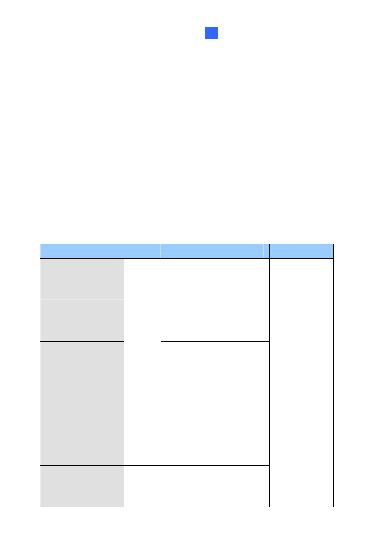
Mini Fixed Dome (GV-MFD)
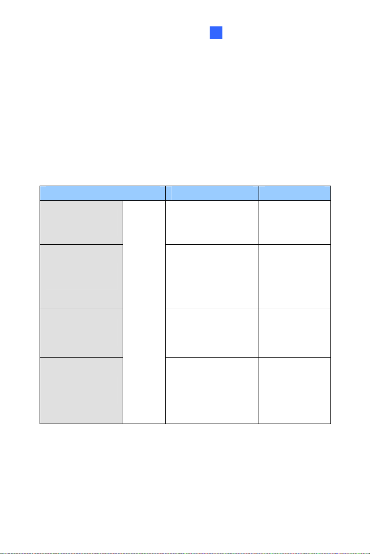
Model No. Specifications Description
GV-MFD120
Fixed Iris, f: 4 mm,
F/1.5, 1/3’’ M12
Mount
1.3 MP Low Lux,
H.264, Color
GV-MFD130
GV-MFD320
Fixed Iris, f: 2.54
mm, F/2.8, 1/2.5’’
M12 Mount
1.3 MP / 2 MP / 3
MP / 5MP, H.264,
Color
GV-MFD1501-0F
GV-MFD2401-0F
GV-MFD2501-0F
GV-MFD3401-0F
GV-MFD5301-0F
Fixed Iris, f: 2.8 mm,
F/2.0, 1/3’’ M12
Mount
GV-MFD1501-1F
GV-MFD2501-1F
Fixed Iris, f: 4 mm,
F/1.5, 1/3’’ M12
Mount
GV-MFD1501-2F
GV-MFD2401-2F
GV-MFD2501-2F
GV-MFD3401-2F
GV-MFD5301-2F
Fixed Iris, f: 8 mm,
F/1.6, 1/3’’ M12
Mount
GV-MFD1501-3F
GV-MFD2401-3F
GV-MFD2501-3F
GV-MFD3401-3F
GV-MFD5301-3F
Fixed Iris, f: 12 mm,
F/1.6, 1/3’’ M12
Mount
GV-MFD1501-4F
GV-MFD2401-4F
Fixed Iris, f: 2.1 mm,
F/1.8, 1/3’’ M12
Mount
GV-MFD1501-5F
GV-MFD2401-5F
GV-MFD2501-5F
GV-MFD3401-5F
GV-MFD5301-5F
Fixed
Lens
Fixed Iris, f: 3.8 mm,
F/1.8, 1/3’’ M12
Mount
1.3 MP Super
Low Lux / 2 MP /
2 MP Super Low
Lux / 3 MP / 5
MP, H.264, Color
2
Mini Fixed & Rugged Dome
1
Model No. Specifications Description
GV-MFD2501-6F
GV-MFD3401-6F
Fixed
Lens
Fixed Iris, f: 2.3mm,
F/2.2, 1/3’’ M12
Mount
2 MP Super Low
Lux / 3 MP WDR
Pro, H.264, Color
Mini Fixed Rugged Dome (GV-MDR)
Model No. Specifications Description
GV-MDR220
GV-MDR320
GV-MDR520
Fixed Iris, f: 2.54
mm, F/2.8, 1/2.5’’
M12 Mount
2 MP / 3 MP / 5MP,
H.264, Color
GV-MDR1500-1F
GV-MDR3400-1F
GV-MDR5300-1F
Fixed Iris, f: 2.8
mm, F/2.0, 1/3’’
M12 Mount
GV-MDR1500-2F
GV-MDR3400-2F
GV-MDR5300-2F
Fixed
Lens
Fixed Iris, f: 3.8
mm, F/1.8, 1/3’’
M12 Mount
1.3 MP super low
lux / 2 MP WDR
Pro / 2 MP super
low lux / 3 MP
WDR Pro / 5 MP,
H.264, Color
3

1.1 Packing List
GV-MFD
• Mini Fixed Dome
• Torx Wrench
• Self Tapping Screw x 2
• Screw Anchor x 2
• Cable stopper
• 2-pin terminal block (for GV-MFD120 / 130 / 320)
• Short-Body RJ-45 Plug (for GV-MFD1501 series / 2401 series /
2501 series / 3401 series / 5301 series)
• USB / Audio Y-cable (for GV-MFD1501 series / 2401 series /
2501 series / 3401 series / 5301 series)
• Power Adapter
• Download Guide
• Warranty Card
Note: The power adapter can be excluded upon request.
4

Mini Fixed & Rugged Dome
1
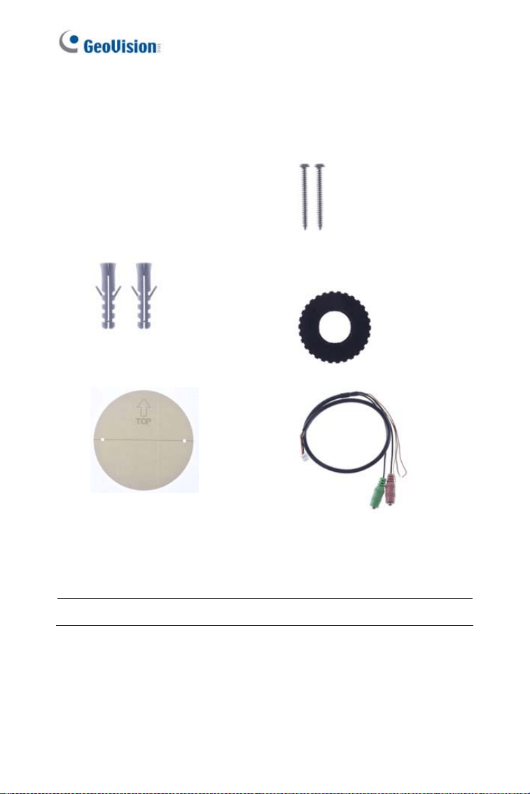
GV-MDR
• Mini Fixed Rugged Dome
• Torx Wrench
• Self Tapping Screw x 2
• Screw Anchor x 2
• Cable stopper
• Cable Connector
• Installation sticker
• Silica gel bag x 2
• Adhesive Tape for Silica Gel Bag x 2
• Ferrite core for vehicle installation
• Download Guide
Note:
1. The power adapter can be excluded upon request.
2. When purchasing GV-MDR1500 / 3400 / 5300, choose one of the
two LAN connector types (for motor vehicles or for general use). For
details, see LAN Connector, 1.2.3 GV-MDR.
5
1.2 Overview
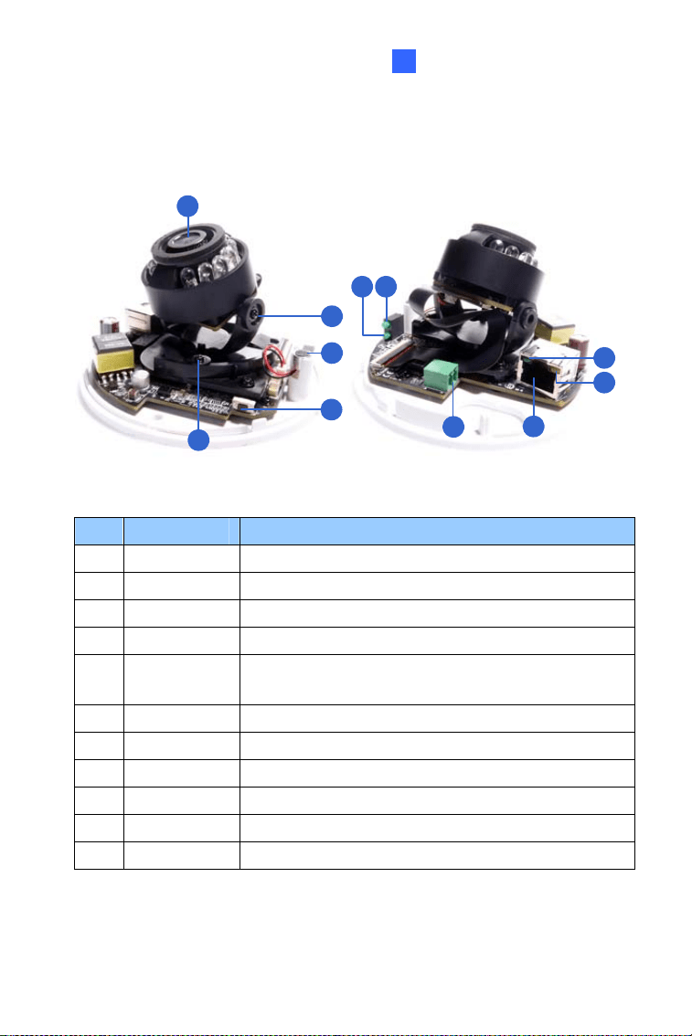
1.2.1 GV-MFD120 / 130 / 320
1 2 43
5
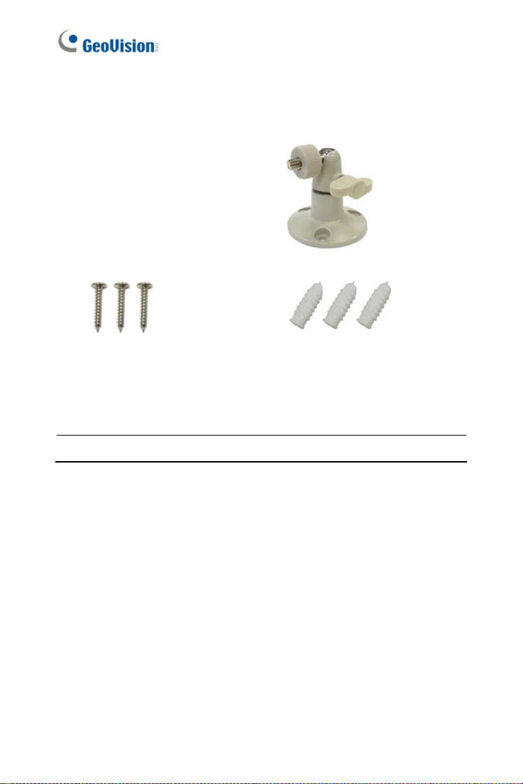
6
7
Figure 1-1
No. Name Description
1 Default Button
Resets the camera to factory default. For
details, see 1.5 Loading Factory Default.
2 Lens Receives image inputs.
3 Tilt Screw Loosens the screw to adjust tilt angle.
4 Microphone Provides one-way audio.
5 Pan Screw Loosens the screw to pan.
6
Mini Fixed & Rugged Dome
1
No. Name Description
6 LED Indicators See LED Indicators below.
7 Memory Card Slot
Inserts a micro SD card (SD/SDHC,
version 2.0 only, Class 10) to store
recording data.
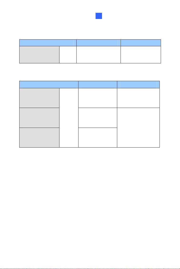
LED Name Description
1. Link Turns on when the network is connected.
2. ACT Turns on when data are being transmitted.
3. PWR Turns on when power is on.
4. SW RDY (Status) Turns on when the system is ready.
7
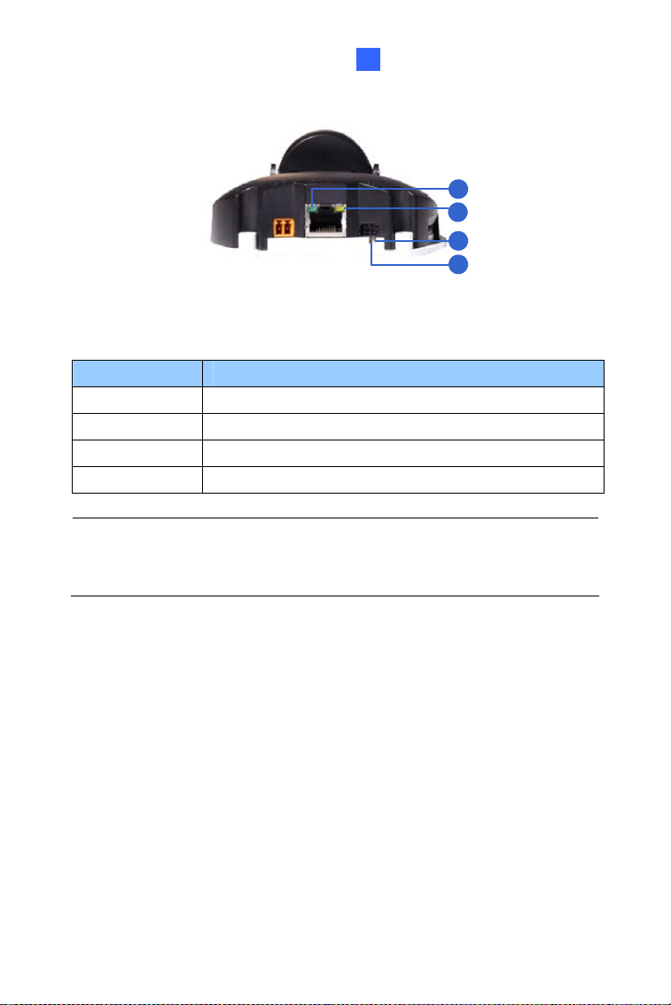
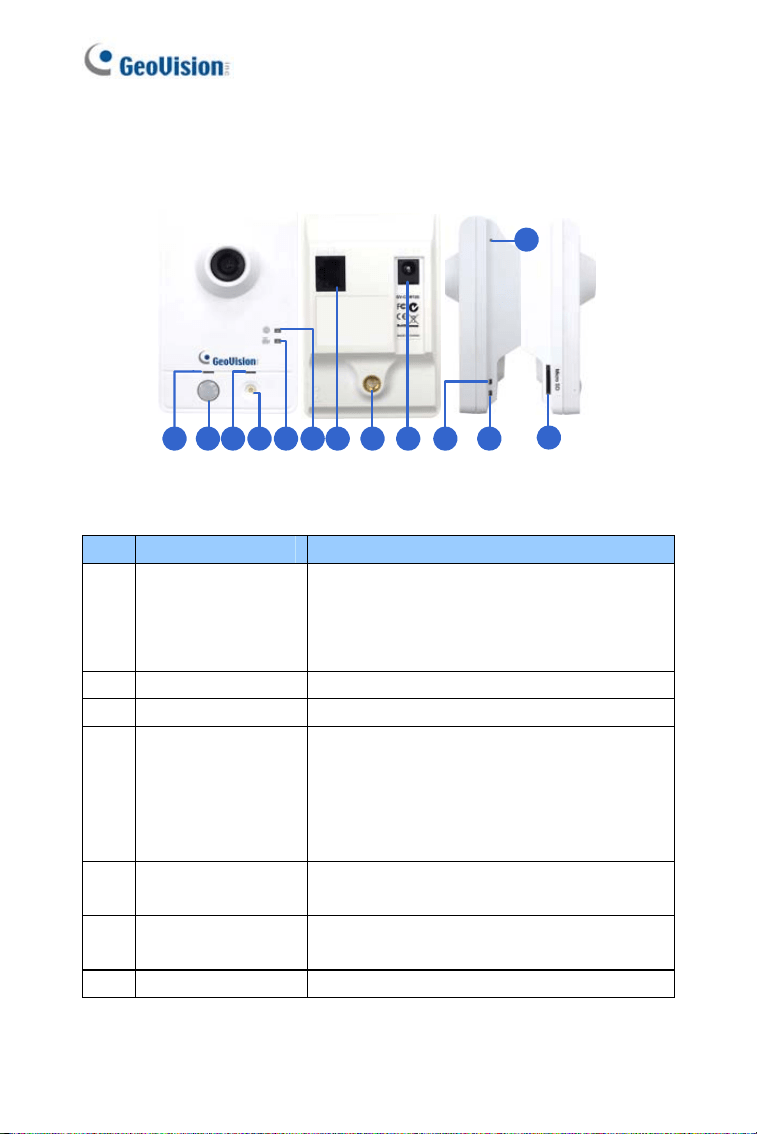
1.2.2 GV-MFD1501 Series / 2401 Series / 2501 Series /
3401 Series / 5301 Series
1
2
3
4
5
8
9
6
7
Figure 1-2
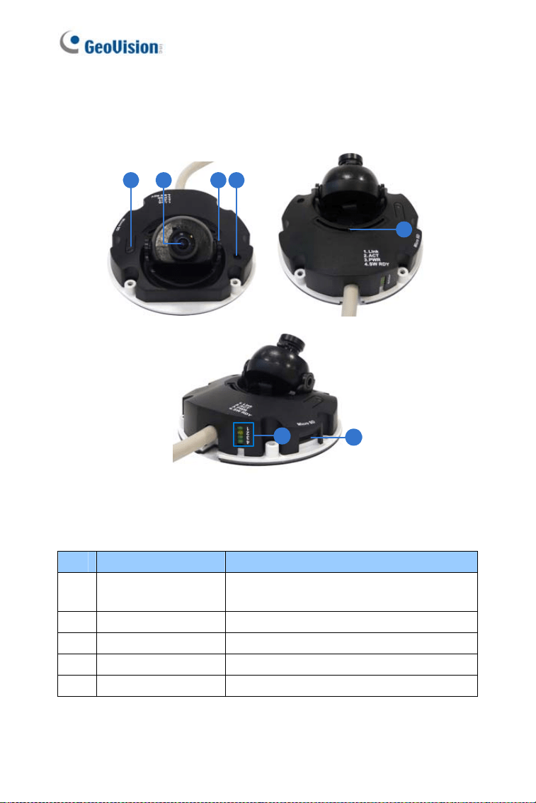
No. Name Description
1 Microphone Receives sound.
2 Pan Screw Loosens the screw to pan.
3 Lens Receives image inputs.
4 Tilt Screw Loosens the screw to adjust tilt angle.
5 Default Button
Resets the camera to factory default. For
details, see 1.5 Loading Factory Default.
6 DC 5V Power Port Connects to power.
7 LAN / PoE Connects to a 10/100 Ethernet or PoE.
8 Memory Card Slot
Inserts a micro SD card (SD/SDHC,
version 2.0 only, Class 10) to store
recording data.
9 USB and Audio Out
Connects to a GV-WiFi Adapter/USB hard
drive and a speaker through the supplied Y
cable.
8
Mini Fixed & Rugged Dome
1
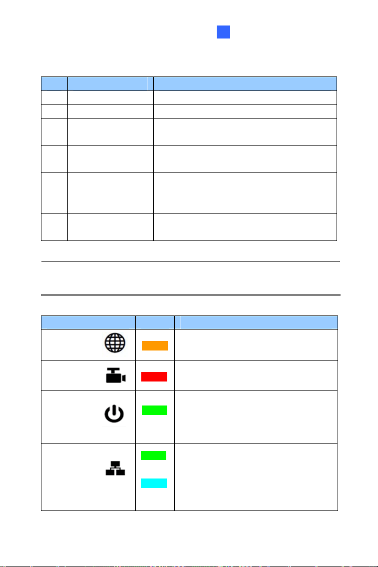
1
2
3
4
Figure 1-3
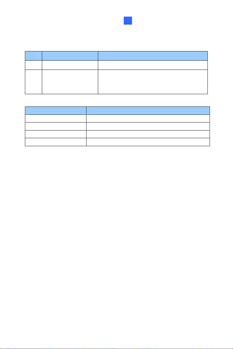
LED Name Description
1. Link Turns on (green) when the network is connected.
2. ACT Turns on (orange) when data are being transmitted.
3. Status Turns on (red) when the system is ready.
4. Power Turns on (green) when power is on.
Note: For details on limitations and requirements of the USB port, refer
to Note for USB Storage and WiFi Adapter at the beginning of this
manual.
9
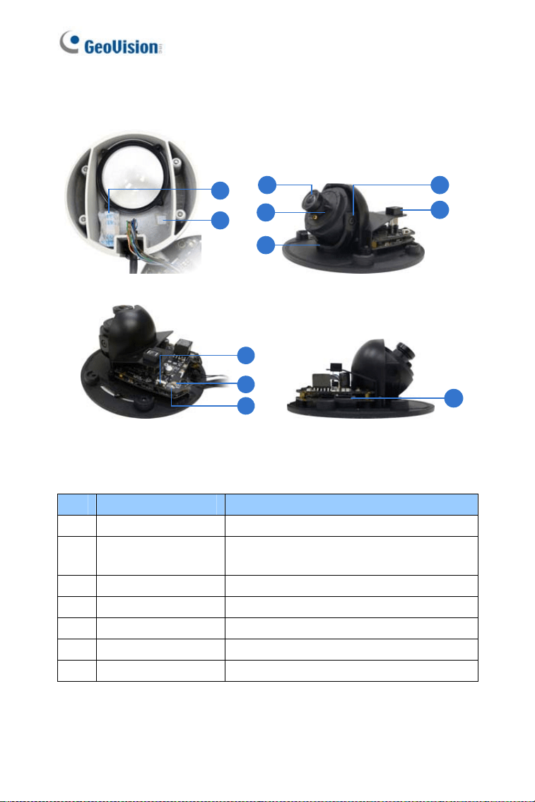
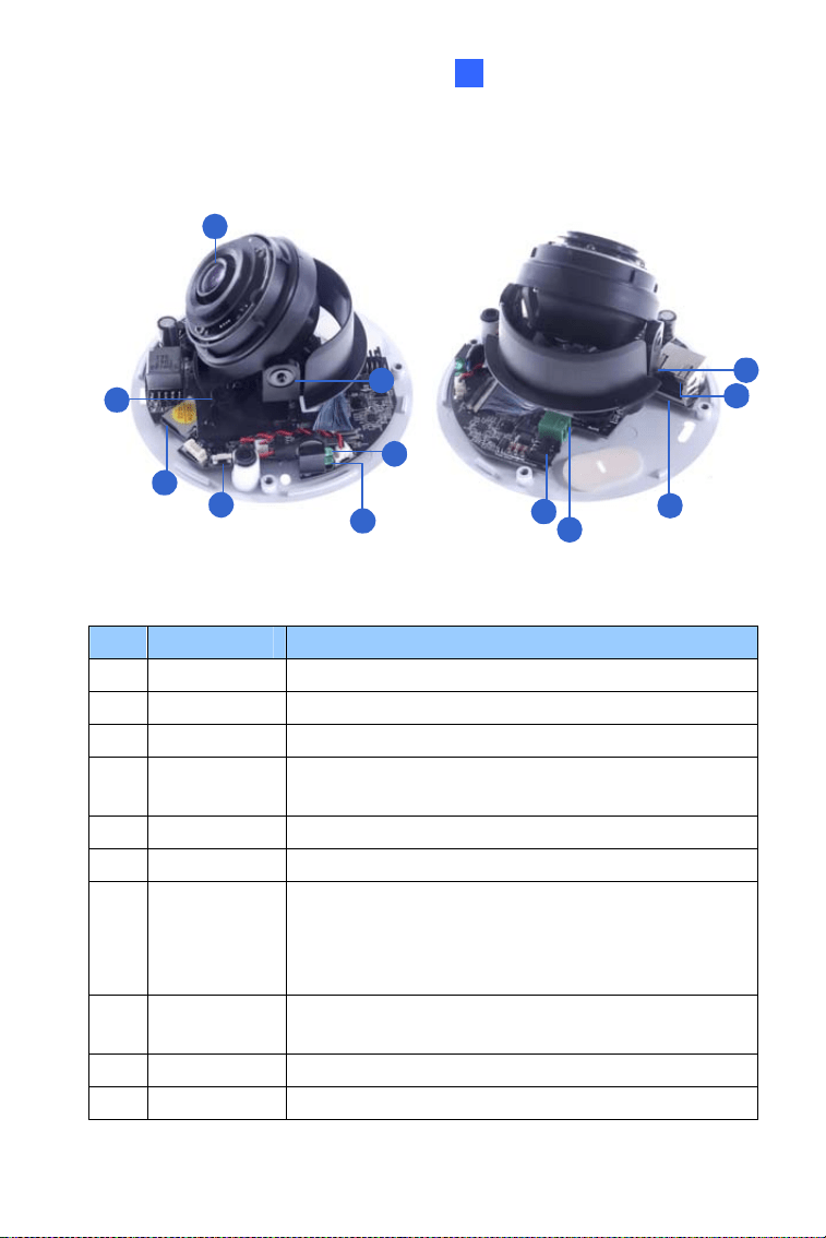
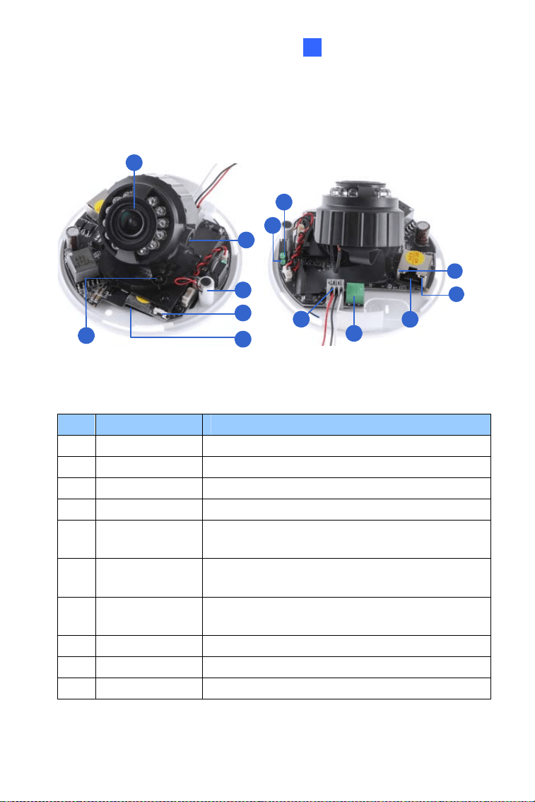
1.2.3 GV-MDR
1
2
3
4
5
6
7
8
9
10
11
Figure 1-4
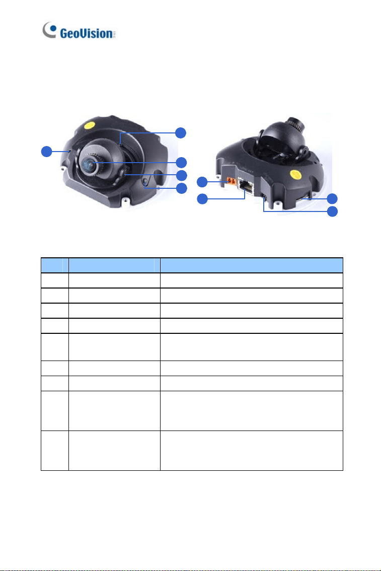
No. Name Description
1 Silica gel bag Absorbs the moisture inside the camera.
2 Conceal paper
Prevents water or moisture from entering
the camera.
3 Lens Receives image inputs.
4 Rotation Disc Rotates the camera lens.
5 Pan Disc Pans the camera lens.
6 Tilt Screw Loosens to tilt the camera.
7 Microphone Provides one-way audio.
10
Mini Fixed & Rugged Dome
1
No. Name Description
8 Default Button
Resets the camera to factory default. For
details, see 1.5 Loading Factory Default.
9
Power and status
LED
Turns red when the power is on. Flashes
orange light twice when the system is
ready.
10 LAN LED Turns on when the network is connected.
11 Memory Card Slot
Inserts a micro SD card (SD/SDHC,
version 2.0 only, Class 10) to store
recording data.
IMPORTANT: In case of damage and possible condensation inside the
camera housing, be sure not to touch or remove the conceal paper.
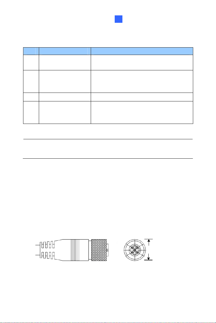
LAN Connector
Two types of LAN connector are available for GV-MDR1500 series / 3400
series / 5300 series. Select an option based on your installation
environment.
1.
Waterproof M12 4-Pin Female Connector
The M12 connector is used for motor vehicles.
Ø14.7 mm (0.58'')
11
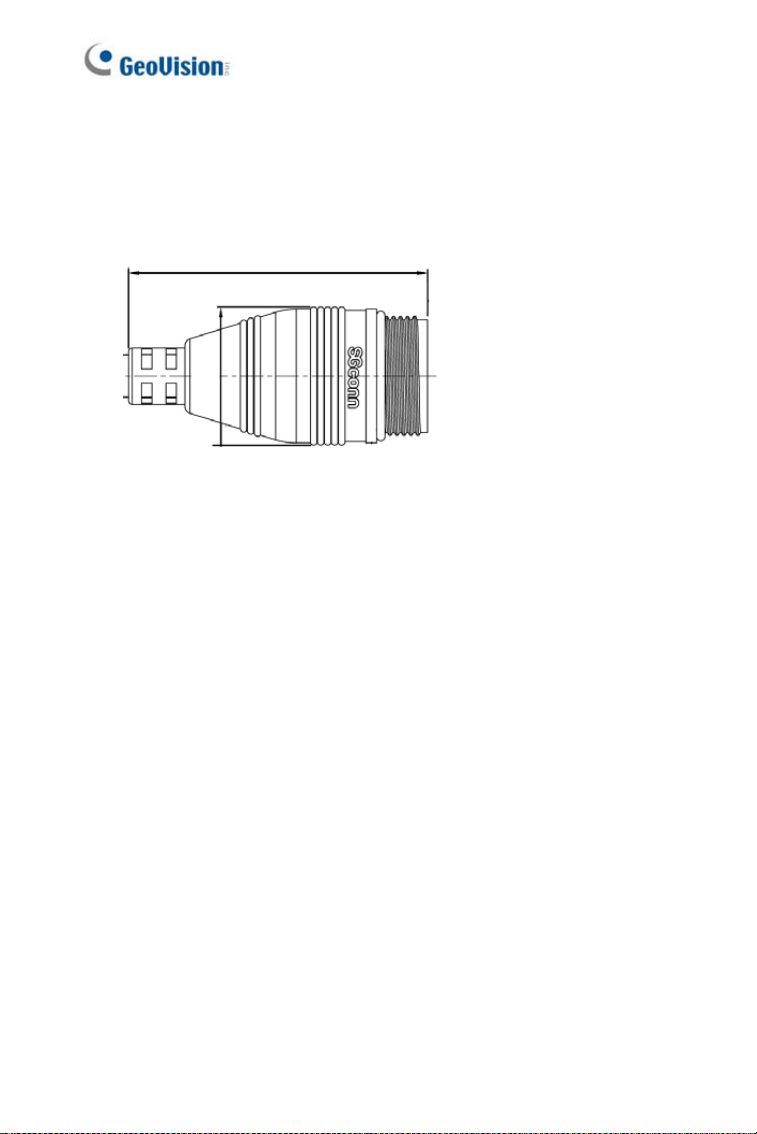
2. Small Waterproof Connector
For this connector type, see 1.3.2 GV-MDR to install the supplied
cable connector.
42.8 mm (1.69")
ø19.6 (0.77”)
12
Mini Fixed & Rugged Dome
1
1.3 Installation
To install a Mini Fixed Dome, make sure the installing site is shielded from
rain and moisture.
1.3.1 GV-MFD Series
1. Unscrew the housing cover using the supplied torx wrench.
2. Put the camera on the desired location and make 2 marks on the
ceiling for screw anchors. If you want to run the cables inside the
ceiling, make a round mark with a diameter of 2.5 cm.
3. Drill the marks and insert the screw anchors.
4. Secure the Mini Fixed Dome to the ceiling with the self-tapping
screws.
5. Connect the camera to network and power. For details, see 1.4
Connecting the Camera.
6. Access the live view. For details, see 7.2 Accessing the Live View.
7. Adjust the angles based on the live view.
Pan Adjustment
Figure 1-5
Tilt Adjustment
Figure 1-6
13
8. Adjust image clarity using the GV-IP Device Utility program. For
details, see 7.3 Adjusting Image Clarity.
9. Insert a Micro SD card (SD/SDHC, version 2.0 only, Class 10) into the
memory card slot (No. 7, Figure 1-1).
10. Secure the housing cover using the supplied torx wrench.
11. Optionally conceal the cable opening with the supplied cable stopper.
Cable stopper
Figure 1-7
14
Mini Fixed & Rugged Dome
1
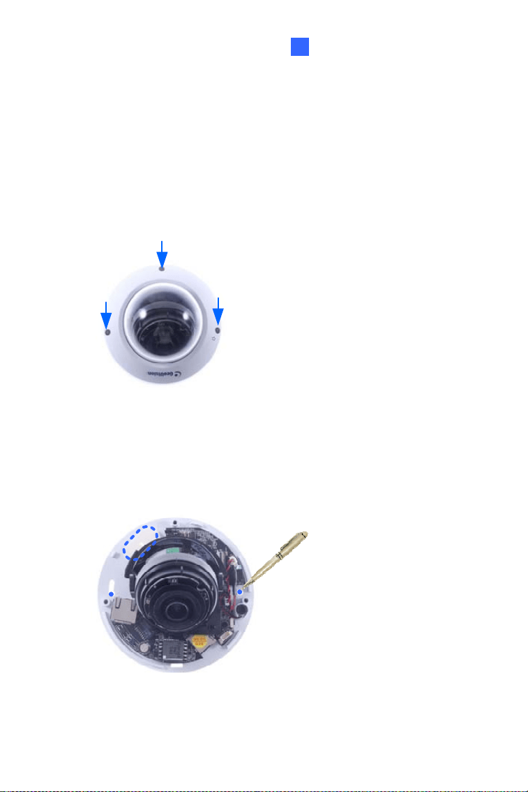
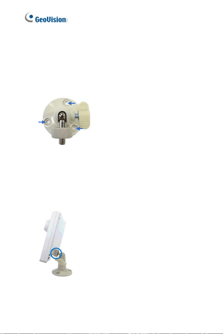
1.3.2 GV-MDR Series
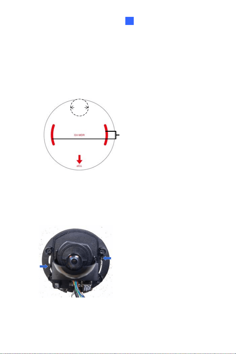
1. Paste the installation sticker on the desired location. The arrow should
point toward the direction that the camera faces.
2. Drill one hole on each of the two curves for screw anchors. Drill the
circle (30 mm in diameter) if you want to run the cable into the ceiling.
Drill a hole
on each
30 mm
Figure 1-8
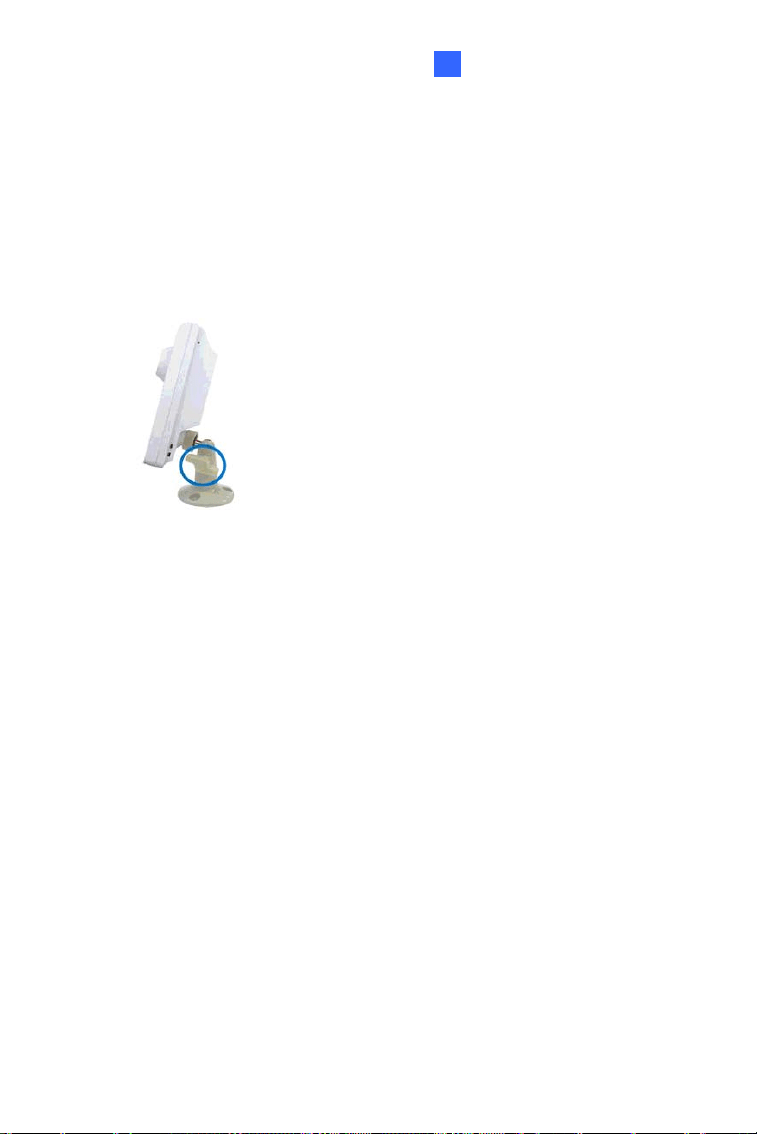
3. Insert the screw anchors.
4. Unscrew the housing cover using the supplied torx wrench.
5. Secure the camera body to the ceiling with the self-tapping screws.
Figure 1-9
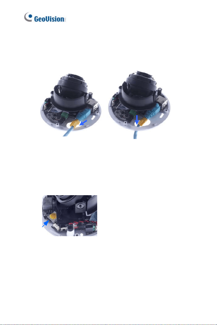
15
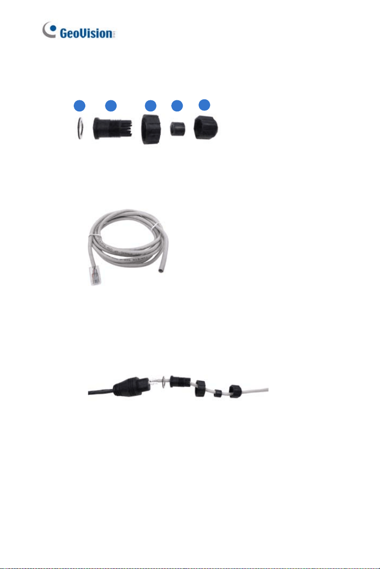
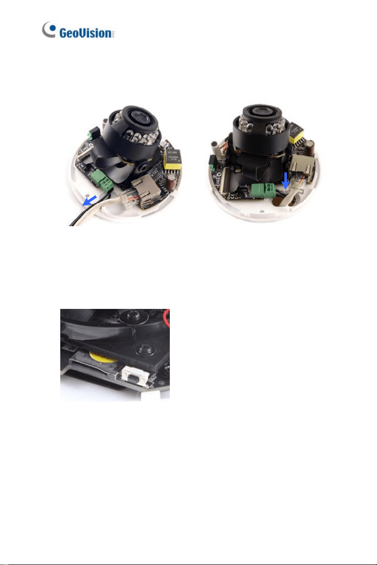
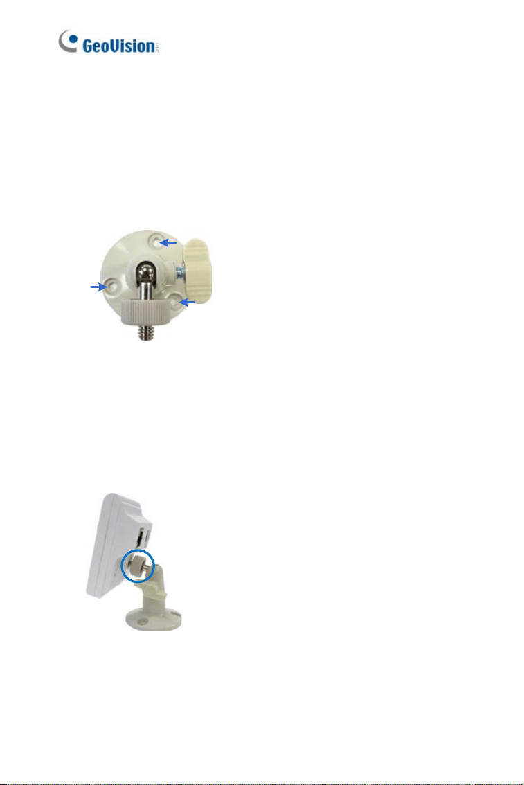
6. Install the cable connector to waterproof the cable. You should have 5
parts:
1 2 3 4
5
Figure 1-10
A. Prepare an Ethernet cable with the RJ-45 connector on one
end only.
Figure 1-11
B. Connect the Ethernet cable to the camera cable.
C. Paste the sticker to the camera cable and slide in all the
components as shown below.
Figure 1-12
16

Mini Fixed & Rugged Dome
1
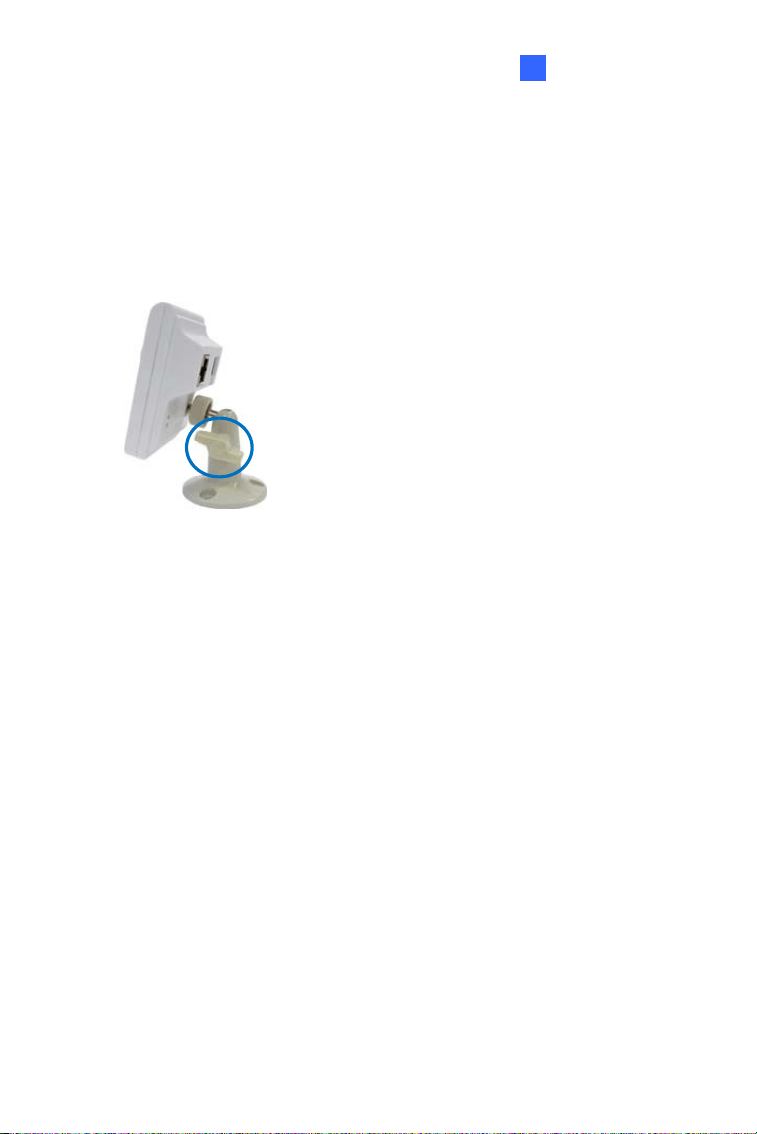
D. Move all the components toward the RJ-45 connector, fit item 4
to item 2, secure item 3 to the camera cable and finally secure
item 5 to item 2 tightly.
Figure 1-13
IMPORTANT: Item 5 must be secured tightly to waterproof the
cable.
7. Access the live view. For details, see 7.2 Accessing the Live View.
17
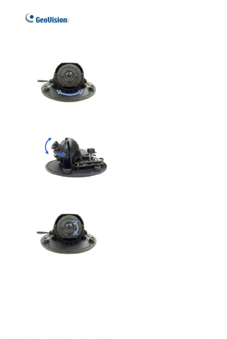
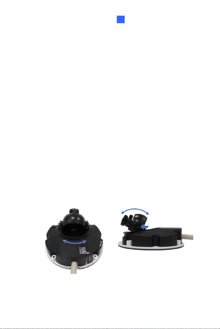
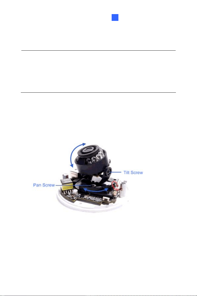
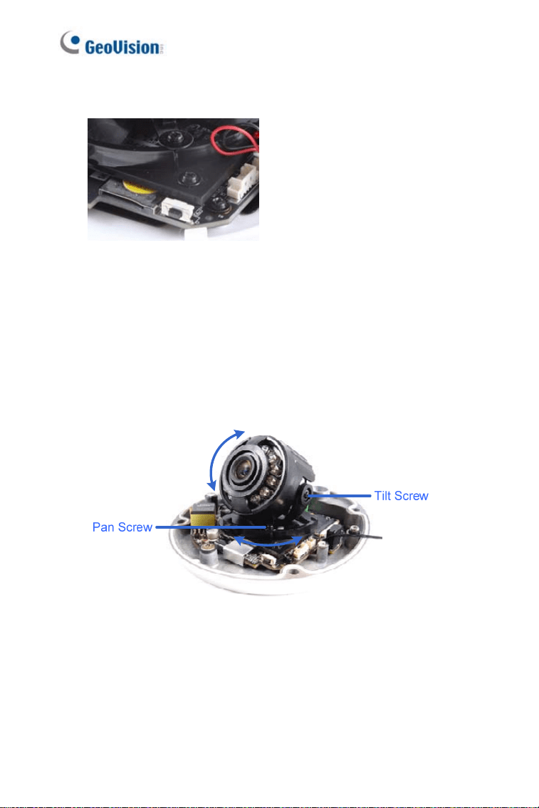
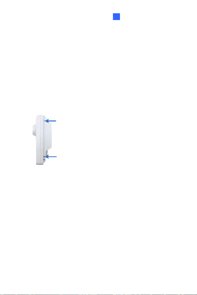
8. Adjust the angles based on the live view.
Pan Adjustment
Figure 1-14
Tilt Adjustment
Figure 1-15
Rotational Adjustment
Figure 1-16
9. Adjust image clarity using the GV-IP Device Utility program. For
details, see 7.3 Adjusting Image Clarity.
10. Insert a Micro SD card (SD/SDHC, version 2.0 only, Class 10) into the
memory card slot (No. 11, Figure 1-2).
18
Mini Fixed & Rugged Dome
1
11. Replace the silica gel bag.
IMPORTANT: The silica gel bag loses it effectiveness when the dry
camera is opened. To prevent the lens from fogging up, replace the
silica gel bag every time you open the camera, and conceal the gel bag
in camera within 2 minutes of exposing to open air.
12. Secure the housing cover using the supplied torx wrench.
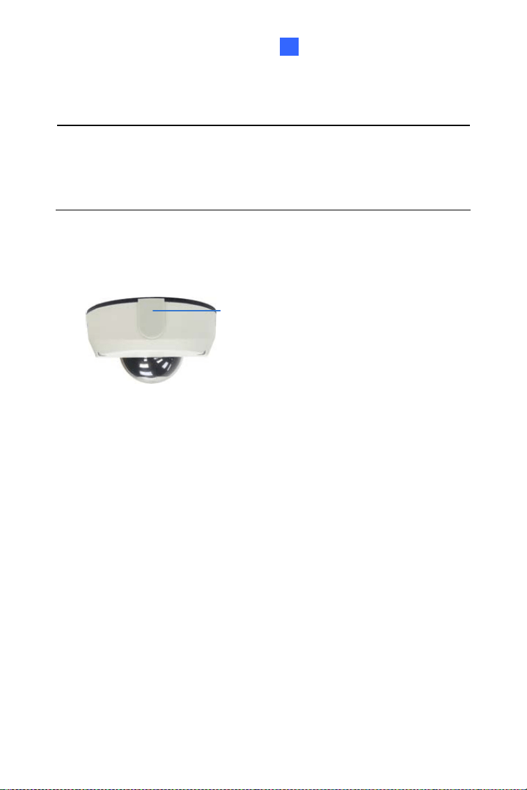
13. Optionally conceal the cable opening with the supplied cable stopper.
Cable stopper
Figure 1-17
19
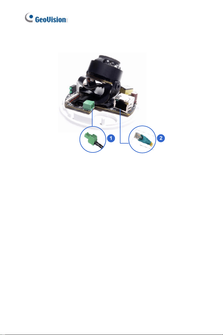
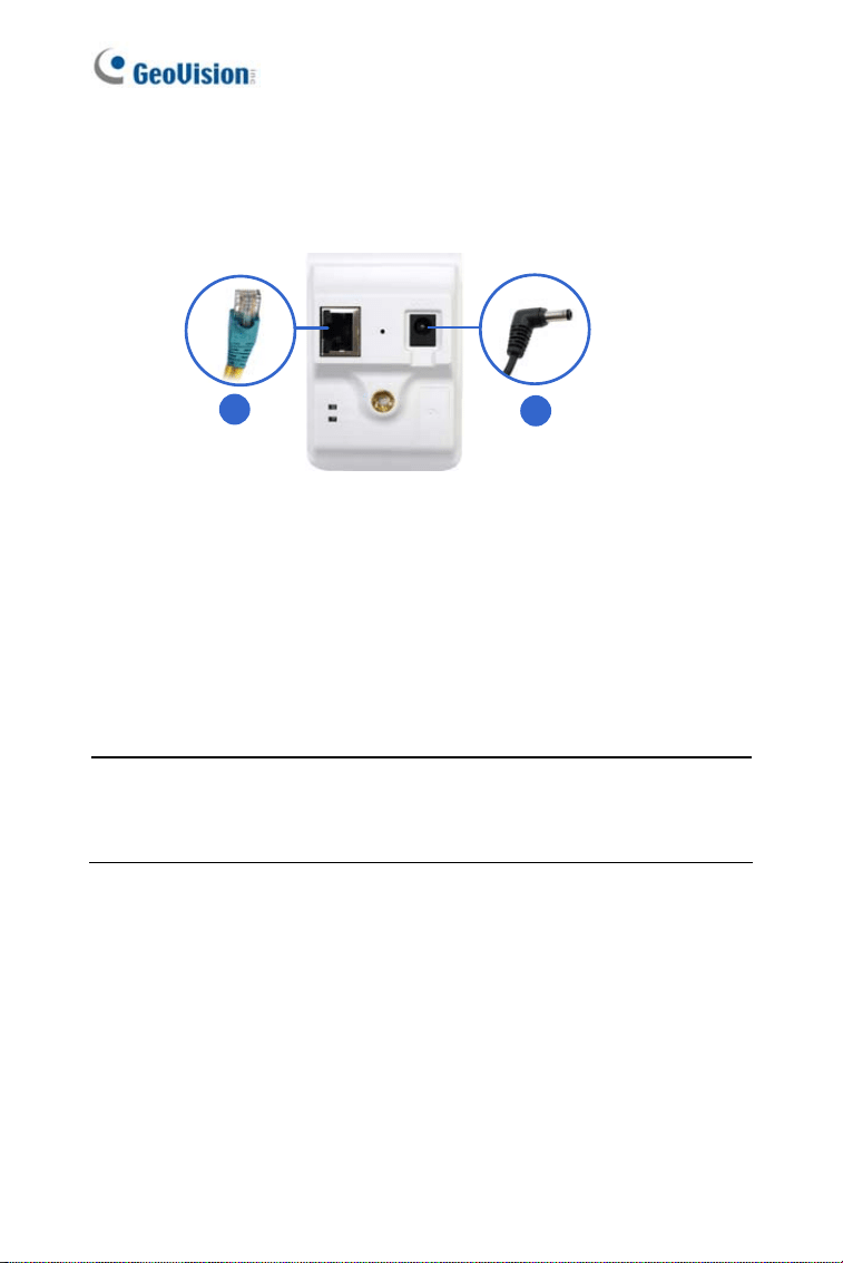
1.4 Connecting the Camera
Refer to the wire definition and illustrations below to connect the power and
network.
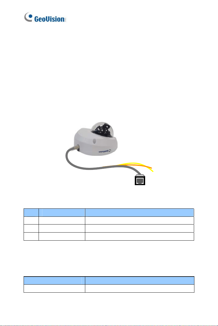
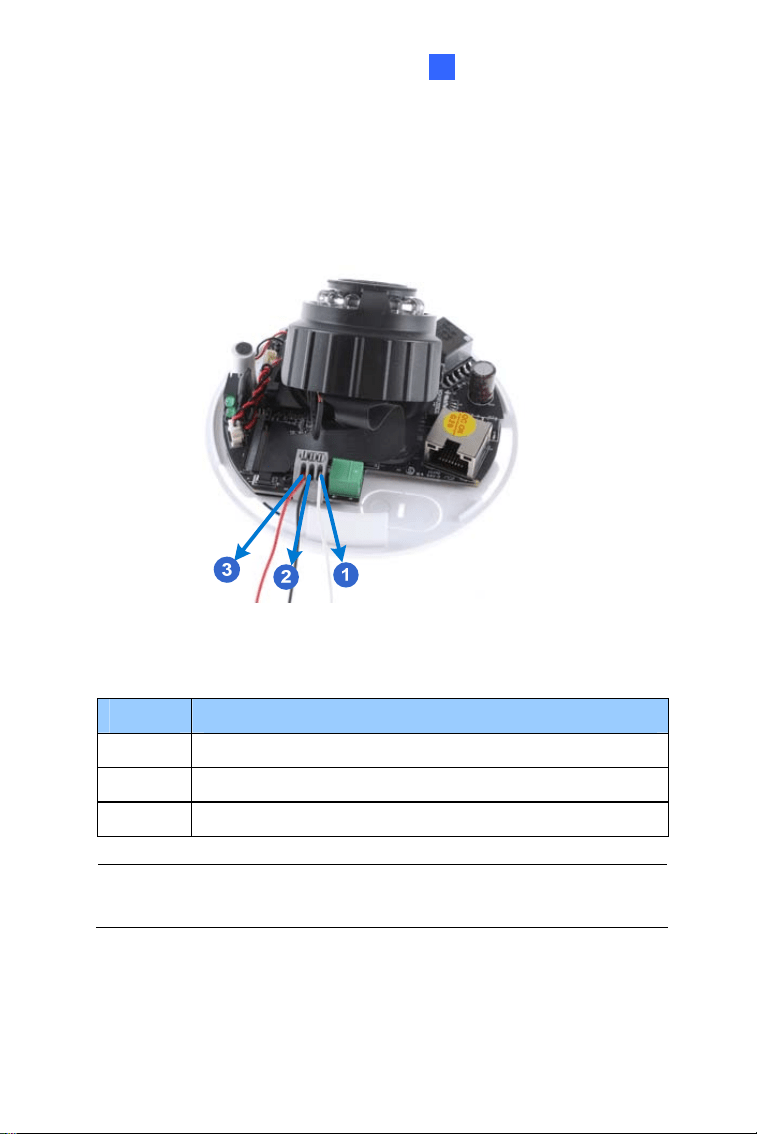
1.4.1 Wire Definition
GV-MFD120 / 130 / 320
The data cable provides connections for power and network access. The
wires are illustrated and defined below:
Figure 1-18
No. Wire Color Definition
1 Yellow DC 12V+
2 Orange GND
3 Gray PoE, Ethernet
GV-MDR Series
Power and network connectivity is provided through a PoE cable.
Wire Color Definition
Gray PoE, Ethernet
20
Mini Fixed & Rugged Dome
1
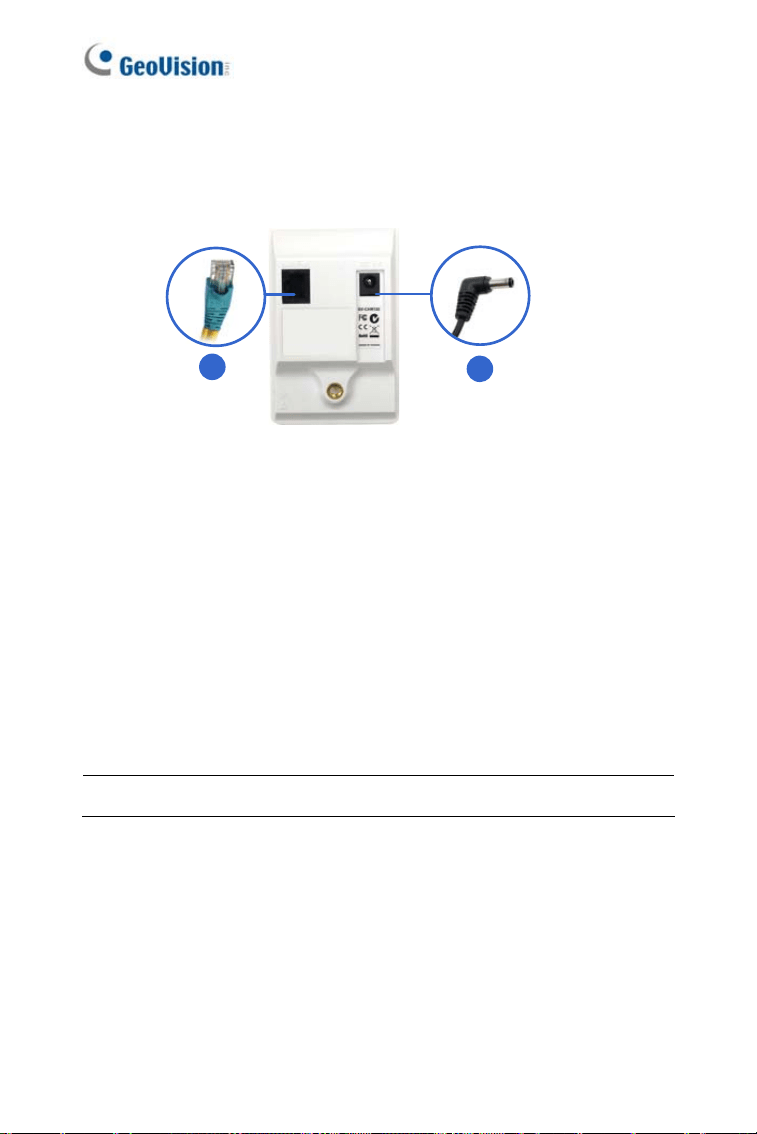
1.4.2 Power and Network Connection
Use one of the following methods to power on and connect your camera to
network:
• Wired connection with PoE: Use a Power over Ethernet (PoE)
adapter to connect the camera to the network, and the power will be
provided at the same time.
• Wired connection with network cable (GV-MFD Series only):
Connect the camera with a standard network cable and use the power
adapter to supply power. For details, see Powering On for GV-MFD
Series below to assemble the terminal block with power adapter.
• Wireless connection (GV-MFD1501 Series / 2401 Series / 2501
Series / 3401 Series / 5301 Series only):
Connect the camera with a
GV-WiFi Adapter (optional accessory) and use the power adapter to
supply power.
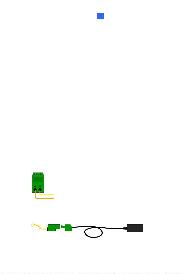
Powering On the GV-MFD120 / 130 / 320
1. Insert the orange wire of the camera to the left pin (-) and the yellow
wire to the right pin (+) of the terminal block.
Figure 1-19
2. Connect the power adapter to the terminal block.
DC 12V Power Adaptor
Terminal Block
Figure 1-20
21
3. Connect the camera to network using a network cable.
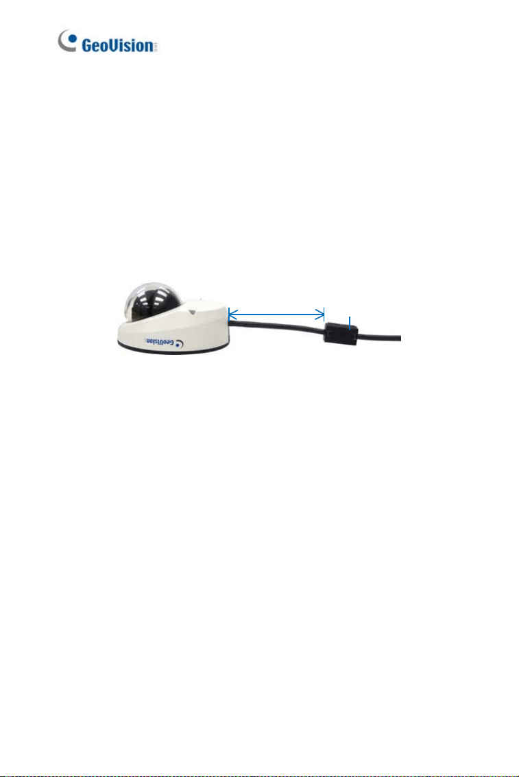
1.4.3 Vehicle Installation
To install the Mini Fixed Rugged Dome on a vehicle, clip the ferrite core
to the camera cable. In accordance to EN 50155, the ferrite core is used
for reduction of the cable-based and radiated interferences, ensuring stable
image quality. The ferrite core must be attached as close as possible to the
camera with the maximum distance of 15 cm.
Max. 15 cm
Ferrite Core
Figure 1-21
22
Mini Fixed & Rugged Dome
1
1.5 Loading Factory Default
You can restore factory default settings through the Web interface or
directly on the camera.
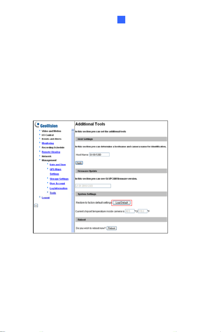
1.5.1 Using the Web Interface
1. On the left menu of Web interface, select Management and select
Tools. The Additional Tools dialog box appears.
2. Click the
Load Default button in the System Settings section.
Figure 1-22
23
24
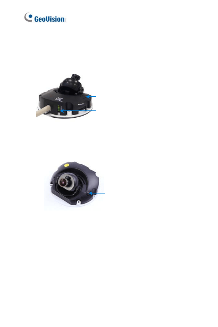
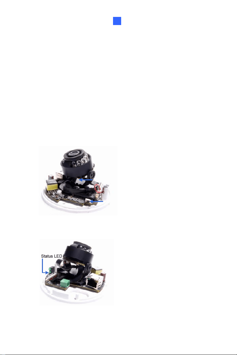
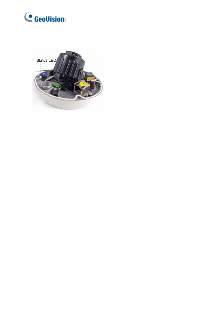
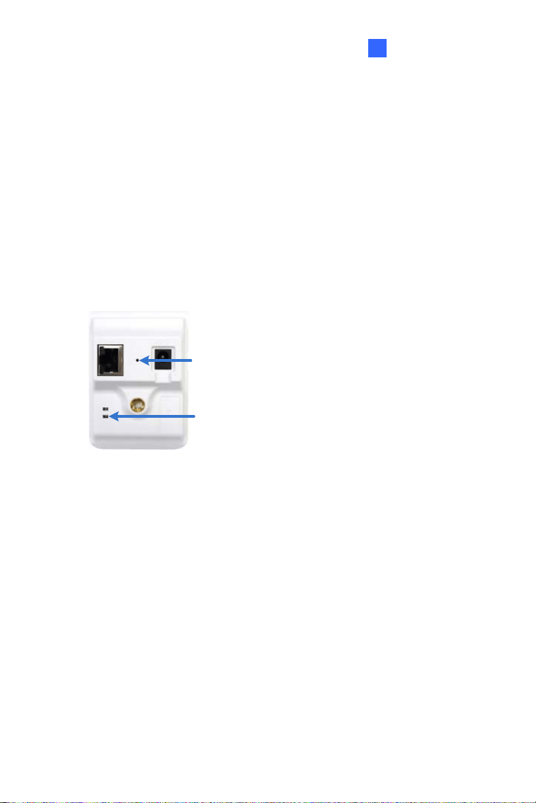
1.5.2 Directly on the Camera
1. Keep the power and network cables (or PoE) connected to the camera.
2. Press and hold the
default button.
Default button
Status LED
Figure 1-23
(GV-MFD120 / 130 / 320)
Default button
Figure 1-24
(GV-MFD1501 Series / 2401 Series / 2501 Series / 3401 Series /
5301 Series)
3. Release the
default button when the status LED blinks. This shall
take about 8 seconds.
4. When the
status LED fades, the process of loading default settings is
completed and the camera reboots automatically.
Mini Fixed Dome (Part II)
2
Chapter 2 Mini Fixed Dome (Part II)
The GV-MFD2700 Series / 4700 Series offers an indoor, fixed, mini-sized
network camera with 3-axis mechanism for easy and flexible installation.
GV-MFD2700 Series / 4700 Series can support H.265 video codec to
achieve better compression ratio while maintaining high picture quality at
reduced network bandwidths. The camera can process scenes with
contrasting intensity of lights and produce clear image using the builtin
WDR Pro. The camera is equipped with a Super Low Lux CMOS image
sensor which allows the camera to provide a color live view in near
darkness.
Model No. Specifications Description
GV-MFD2700-0F
Fixed Iris, f: 2.8 mm,
F/2.0, 1/2.7” M12 Mount
GV-MFD2700-2F
Fixed Iris, f: 3.8 mm,
F/1.8, 1/2.7” M12 Mount
GV-MFD2700-6F
Fixed Iris, f: 2.3 mm,
F/2.2, 1/2.7” M12 Mount
2 MP, H.265,
Super Low
Lux, WDR
Pro
GV-MFD4700-0F
Fixed Iris, f: 2.8 mm,
F/2.0, 1/2.7” M12 Mount
GV-MFD4700-2F
Fixed
Lens
Fixed Iris, f: 3.8 mm,
F/1.8, 1/2.7” M12 Mount
GV-MFD4700-6F
Fixed Iris, f: 2.3 mm,
F/2.2, 1/2.7” M12 Mount
4 MP, H.265,
Super Low
Lux, WDR
Pro
25
2.1 Packing List
y H.265 Mini Fixed IP Dome
y Screw x 2
y Screw Anchor x 2
y Focus Adjustment Ring
(only for GV-MFD2700-0F/2F
and GV-MFD4700-0F/2F)
y Installation Sticker
y Audio and I/O extended cable
y Torx Wrench
y Download Guide
y Warranty Card
Note: Power adapters can be purchased upon request.
26
Mini Fixed Dome (Part II)
2
2.2 Overview
1
3
2
5
d
a
b
6
c
7
4
8
Figure 2-1
No. Name Description
1. Lens Receives image inputs.
2. Pan Screw Loosens the screw to adjust pan angle.
3. Tilt Screw Loosens the screw to adjust tilt angle.
4.
Default
Button
Resets the camera to factory default. For details,
see 2.5 Loading Factory Default.
5. DC 12V Port Connects to power.
6. LAN / PoE Connects to a 10/100 Ethernet or PoE.
7.
Audio and
I/O Terminal
Block
Connects the camera to a microphone or a speaker
and to one input and one output devices using
audio and I/O extended cable. For details, see 2.4
Connecting the Camera.
8.
Memory
Card Slot
Inserts a micro SD card (SD/SDHC/SDXC/UHSI,
Class 10) to store recording data.
a Status Turns on (green) when the system is ready.
b Power Turns on (green) when power is on.
27

c Link Turns on (green) when the network is connected.
d ACT Turns on (orange) when data are being transmitted.
28
Mini Fixed Dome (Part II)
2
2.3 Installation
The Mini Fixed Dome can be installed on the wall or the ceiling. Before
installing the camera, make sure the installing site is shielded from rain and
moisture.
1. Open the housing cover by unscrewing the three screws.
Figure 2-2
2. Place the camera where you want to install it, and make 2 marks on
the ceiling or the wall for screw anchors. If you want to run the cables
inside the ceiling or the wall, make a round mark with a diameter of
2.5 cm.
Figure 2-3
29
3. Drill the marks and insert the screw anchors.
4. Thread the power and / or network cable(s) through the oval-shaped
hole or the cable opening on the side.
Figure 2-4
5. Connect the camera to network, power, a microphone or a speaker,
and one input and one output devices. For details, see 2.4
Connecting the Camera.
6. Optionally insert a memory card.
7. Secure the camera to the ceiling or the wall with the supplied screws.
8. Access the live view. For details, see 7.2 Accessing the Live View.
9. Adjust image clarity using the GV-IP Device Utility program. For
details, see 7.3 Adjusting Image Clarity.
30
Mini Fixed Dome (Part II)
2
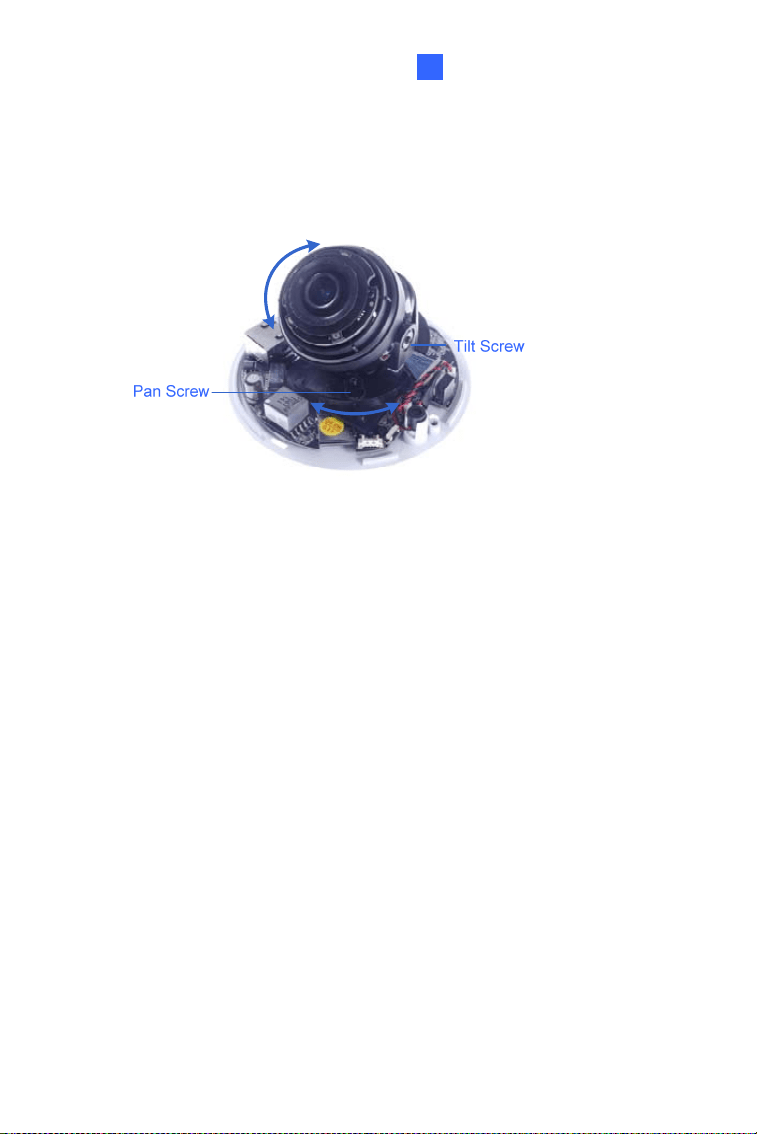
10. Loosen the tile screw, pan screw or rotational screw. Adjust the
angles based on the live view as needed, and tighten the screws
again.
Figure 2-5
11. Place the housing cover back and turn to secure it.
31
2.4 Connecting the Camera
2.4.1 Wire Definition
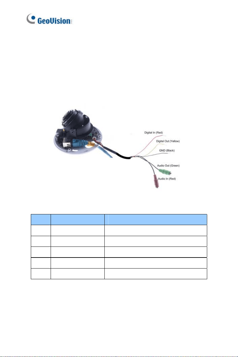
The supplied audio and I/O extended cable allows you to connect one
sensor input and alarm output, and one microphone and speaker.
Figure 2-6
NO. Wire Color Definition
1. Red Digital In
2. Yellow Digital Out
3. Black Ground
4. Red RCA Audio in
5. Green RCA Audio out
For details on how to enable an installed I/O device, see 4.3 I/O Settings,
GV-IPCam Firmware Manual.
32
Mini Fixed Dome (Part II)
2
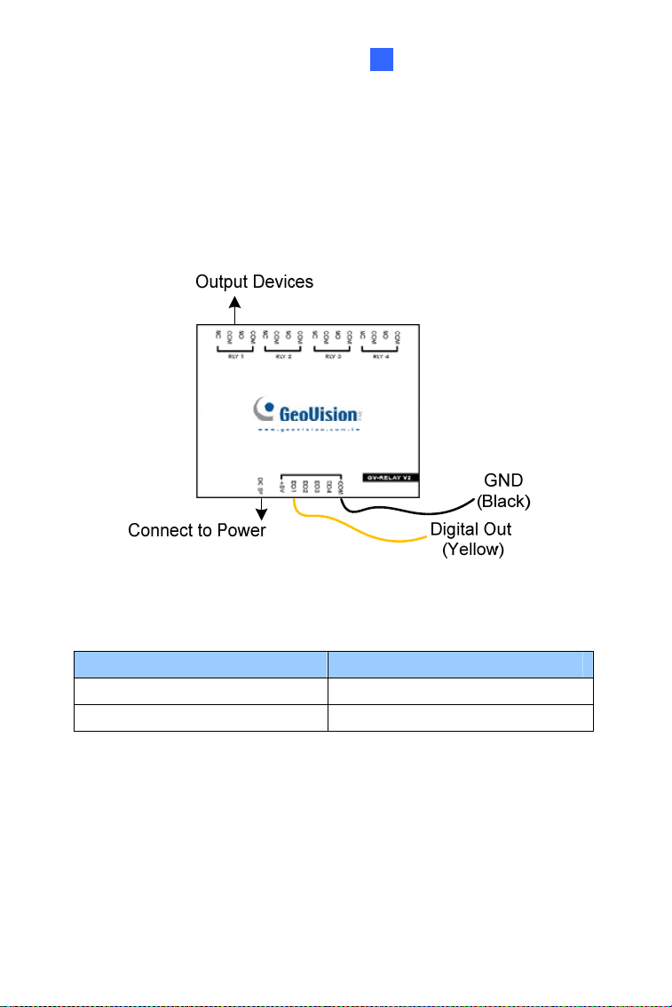
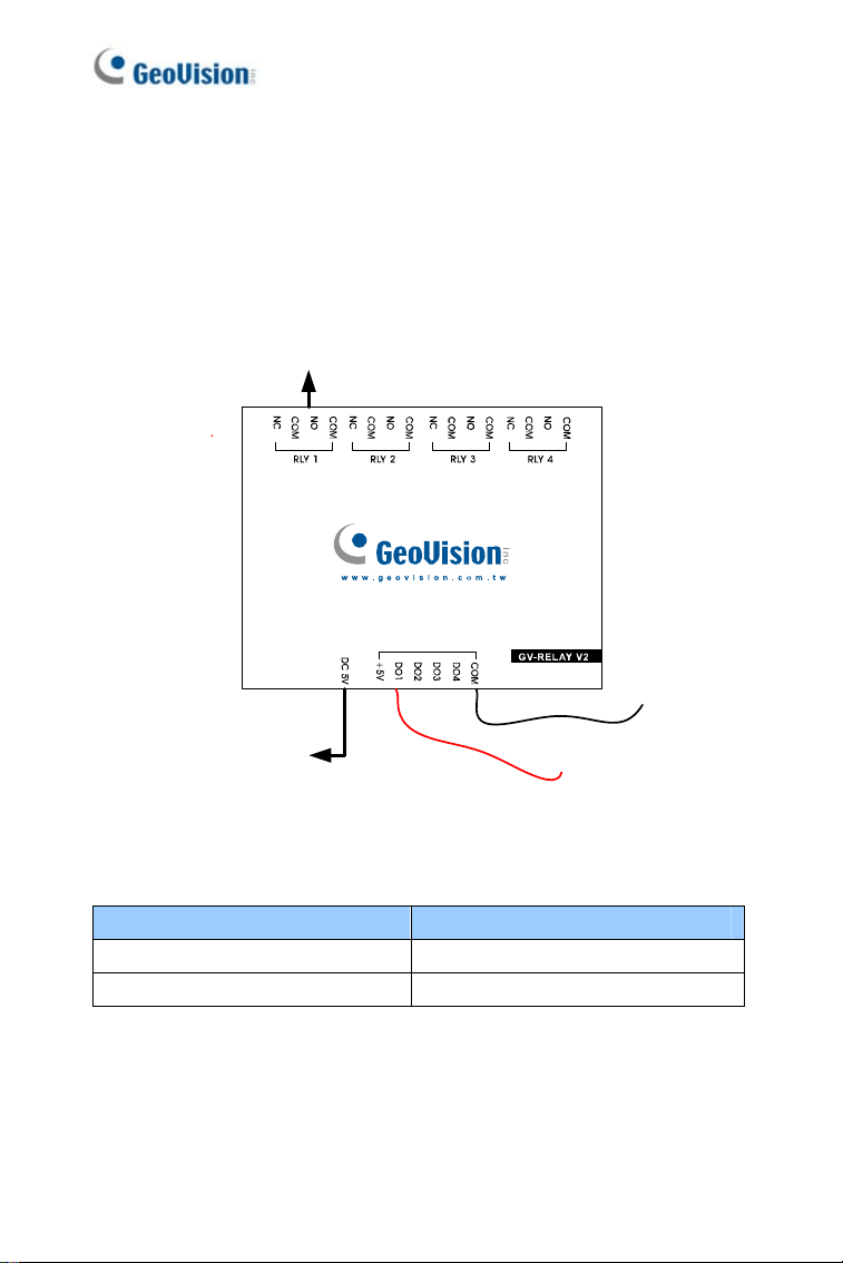
2.4.2 Voltage Load Expansion (Optional)
The camera can only drive a maximum load of 200mA 5V DC. To expand
the maximum voltage load to
10A 250V AC, 10A 125V AC or 5A 100V DC,
connect the camera to a GV-Relay V2 module (optional product). Refer to
the figure and table below.
Figure 2-7
GV-Relay V2 Mini Fixed Dome
COM Ground (Black)
DO1 Digital Out (Yellow)
33
34
2.5 Loading Factory Default
2.5.1 Using the Web Interface
You can restore factory default settings through the Web interface. For
details, see 1.5.1 Using the Web Interface.
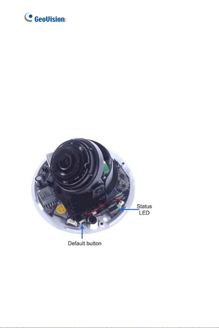
2.5.2 Directly on the Camera
Keep the power connected to the camera. Press and hold the default
button for about
8 seconds. Release the button when the status LED
blinks. For details, see 1.5.2 Directly on the Camera.
Figure 2-7
Target Mini Fixed Dome
3
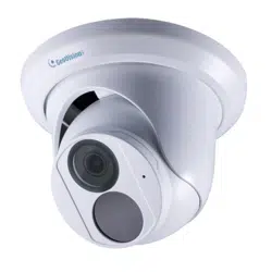
Chapter 3 Target Mini Fixed Dome
The Target Mini Fixed Dome (GV-EFD) is an indoor, fixed, mini-sized
network camera equipped with an automatic IR-cut filter and IR LEDs for
day and night surveillance. Adjustable in 2 axis (pan and tilt), it offers an
entry-level surveillance solution with all the essential features and excellent
image quality.
Model No. Specifications Description
GV-EFD1100-0F
GV-EFD2100-0F
Fixed Iris, f: 2.8 mm,
F/2.0, 1/2.7” M12
Mount
1.3 MP / 2 MP,
H.264, Low
Lux
GV-EFD2700-0F
GV-EFD4700-0F
Fixed Iris, f: 2.8 mm,
F/2.0, 1/2.7” M12
Mount
2 MP, 4 MP,
H.265, Super
Low Lux, WDR
Pro
GV-EFD1100-2F
GV-EFD2100-2F
Fixed Iris, f: 3.8 mm,
F/1.8, 1/2.7” M12
Mount
1.3 MP / 2 MP,
H.264, Low
Lux
GV-EFD2700-2F
GV-EFD4700-2F
Fixed
Lens
Fixed Iris, f: 3.8 mm,
F/1.8, 1/2.7” M12
Mount
2 MP, 4 MP,
H.265, Super
Low Lux, WDR
Pro
35

3.1 Packing List
• Target Mini Fixed Dome (for GV-EFD1100 Series / 2100 Series)
• H.265 Mini Fixed Dome (for GV-EFD2700 Series / 4700 Series)
• Screw x 2
• Screw Anchor x 2
• Focus Adjustment Ring
• Download Guide
• Warranty Card
Note: Power adapters can be purchased upon request.
36
Target Mini Fixed Dome
3
3.2 Overview
1
3
2
5
d
a b
6
c
7
4
Figure 3-1
No. Name Description
1 Lens Receives image inputs.
2 Pan Screw Loosens the screw to adjust pan angle.
3 Tilt Screw Loosens the screw to adjust tilt angle.
4 Microphone Receives sound.
5
Default
Button
Resets the camera to factory default. For details,
see 3.5 Loading Factory Default.
6 DC 12V Port Connects to power.
7 LAN / PoE Connects to a 10/100 Ethernet or PoE.
a Status Turns on (green) when the system is ready.
b Power Turns on (green) when power is on.
c Link Turns on (green) when the network is connected.
d ACT Turns on (orange) when data are being transmitted.
37

Note:
The TV-out function can only be used during installation to adjust
the focus of the camera. To use the TV out function, connect the
supplied black BNC connector to a monitor and select your signal format
(NTSC or PAL) at the
TV Out field on the Web interface. The default
signal format is NTSC. For details, see 4.1.1 Video Settings, GV-IPCam
Firmware Manual.
38
Target Mini Fixed Dome
3
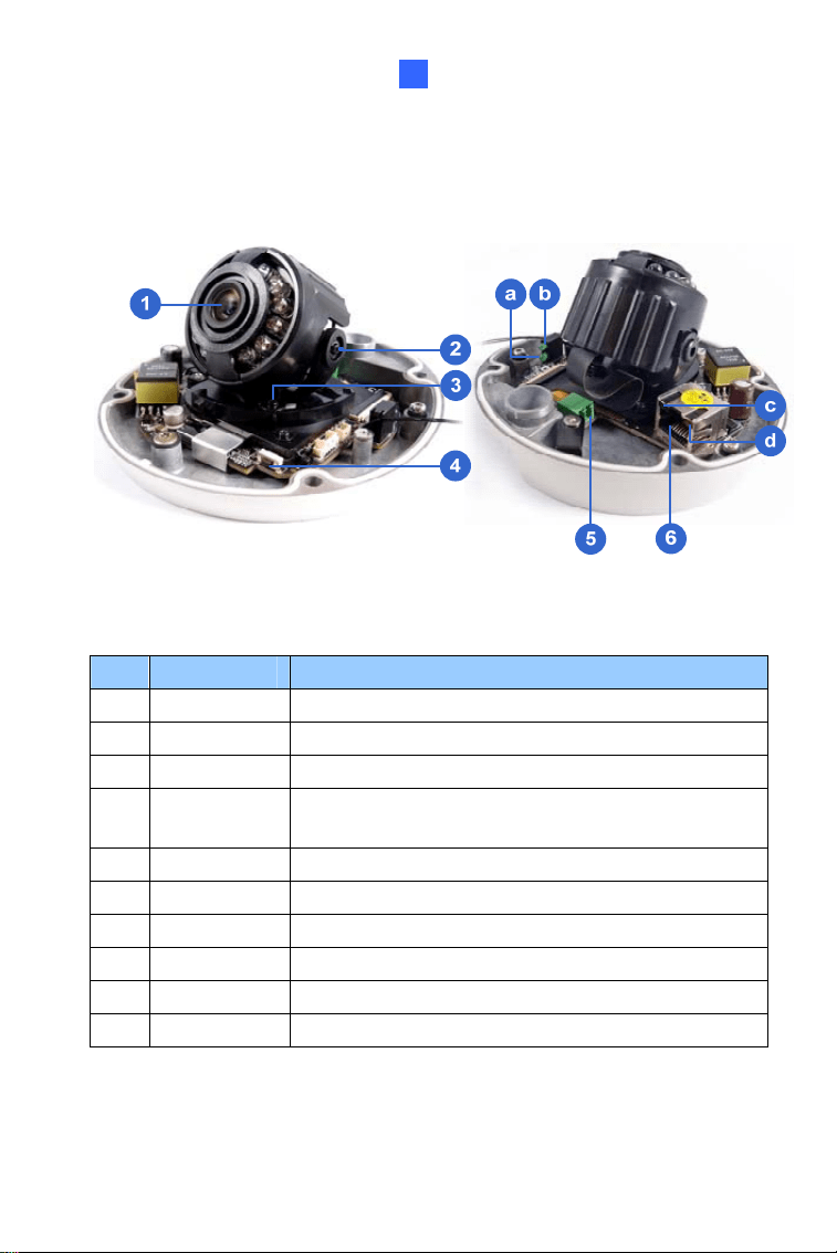
3.2.1 GV-EFD2700
1
3
2
5
d
a
b
6
c
9
4
7
8
Figure 3-2
No.
Name Description
1 Lens Receives image inputs.
2 Pan Screw Loosens the screw to adjust pan angle.
3 Tilt Screw Loosens the screw to adjust tilt angle.
4 Microphone Receives sound.
5 Default Button
Resets the camera to factory default. For details,
see 3.5 Loading Factory Default.
6
Memory Card
Slot
Inserts a micro SD card (SD/SDHC/UHSI,
Class 10) to store recording data.
7
I/O Terminal
Block
The connectors for the digital input and output.
For details, see 3.4.1 I/O Connector.
8 DC 12V Port Connects to power.
9 LAN / PoE Connects to a 10/100 Ethernet or PoE.
a Status Turns on (green) when the system is ready.
39

b Power Turns on (green) when power is on.
c Link
Turns on (green) when the network is
connected.
d ACT
Turns on (orange) when data are being
transmitted.
40
Target Mini Fixed Dome
3
3.3 Installation
The Target Mini Fixed Dome can be installed on the wall or the ceiling.
Before installing the camera, make sure the installing site is shielded from
rain and moisture.
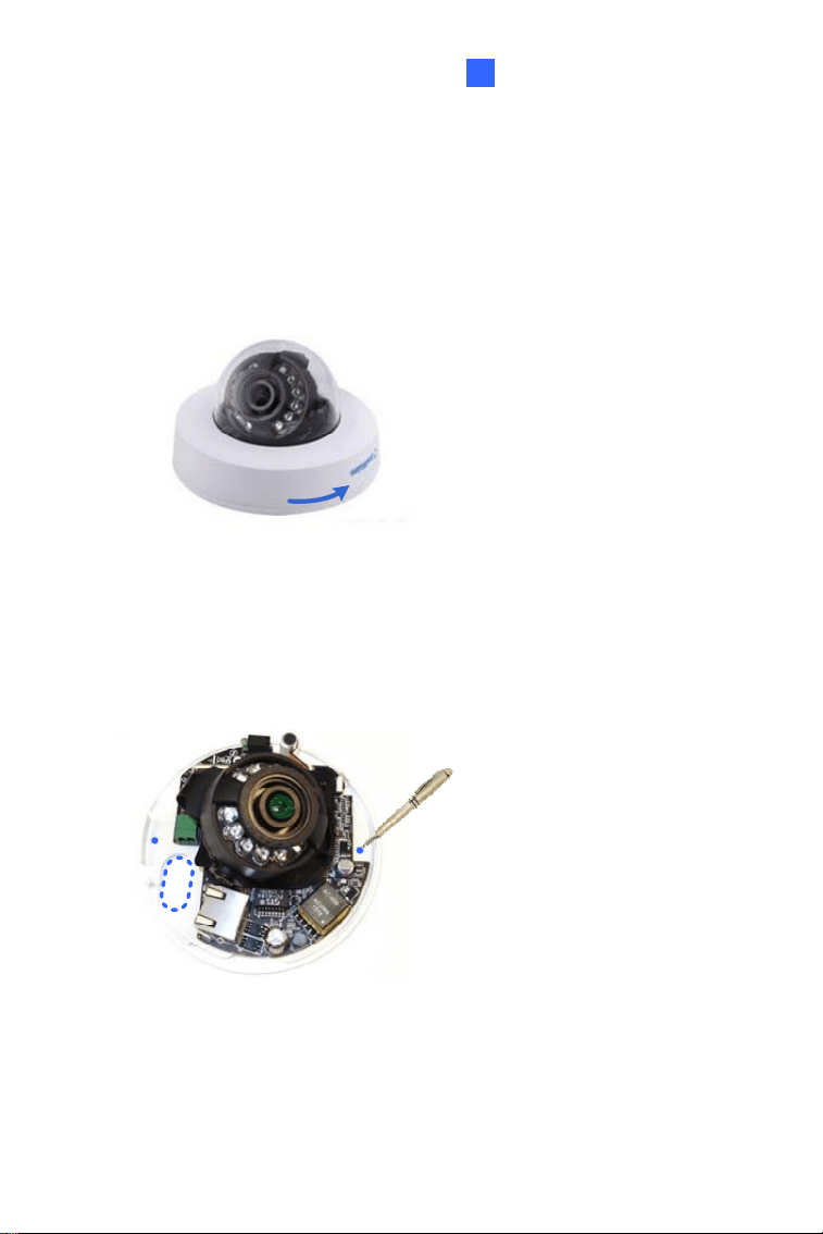
1. Open the housing cover by turning.
Figure 3-2
2. Place the camera where you want to install it, and make 2 marks on
the ceiling or the wall for screw anchors. If you want to run the cables
inside the ceiling or the wall, make a round mark with a diameter of
2.5 cm.
Figure 3-3
3. Drill the marks and insert the screw anchors.
41
4. Thread the power or network cable through the oval-shaped hole or
the cable opening on the side.
Figure 3-4
5. Connect the camera to network and power. For details, see 3.4
Connecting the Camera.
6. Only for GV-EFD2700, insert a memory card.
Figure 3-5
7. Secure the camera to the ceiling or the wall with the supplied screws.
42
Target Mini Fixed Dome
3
8. Access the live view. For details, see 7.2 Accessing the Live View.
Note: The TV-out function can only be used during installation to adjust
the focus of the camera. To use the TV out function, connect the
supplied black BNC connector to a monitor and select your signal format
(NTSC or PAL) at the
TV Out field on the Web interface. The default
signal format is NTSC. For details, see 4.1.1 Video Settings, GV-IPCam
Firmware Manual.
9. Adjust image clarity using the GV-IP Device Utility program. For
details, see 7.3 Adjusting Image Clarity.
10. Loosen the tile screw, pan screw or rotational screw. Adjust the
angles based on the live view as needed, and tighten the screws
again.
Figure 3-6
11.
Place the housing cover back and turn to secure it.
43
3.4 Connecting the Camera
Figure 3-7
1. Connect power using one of the following methods:
• Plug the power adapter to the 12V terminal block. The power
adapter is an optional device. For detail, see Options in the
manual.
• Use the Power over Ethernet (PoE) function and the power will be
provided over the network cable.
The power and status LEDs shall turn on (green).
2. Use a standard network cable to connect the camera to your network.
3. You are ready to access the live view, adjust the image clarity and
configure the basics. See Chapter 7, Accessing the Camera.
44
Target Mini Fixed Dome
3
3.4.1 I/O Connector
For the GV-EFD2700 only, the I/O extended cable allows you to connect
one sensor input and one alarm output.
Figure 3-8
NO. Definition
1. Digital In
2. Ground
3. Digital Out
Note: The I/O cable is not included in the packing list. The users
must prepare them additionally.
For details on how to enable an installed I/O device, see 4.3 I/O Settings,
GV-IPCam Firmware Manual.
45
46
3.4.2 Voltage Load Expansion (Optional)
The GV-EFD2700 can only drive a maximum load of 200mA 5V DC. To
expand the maximum voltage load to
10A 250V AC, 10A 125V AC or 5A
100V DC
, connect the camera to a GV-Relay V2 module (optional product).
Refer to the figure and table below.
Connect to Power
Output Device
Ground
Digital Out
Figure 3-9
GV-Relay V2 Mini Fixed Dome
COM Ground
DO1 Digital Out
Target Mini Fixed Rugged Dome
4
3.5 Loading Factory Default
3.5.1 Using the Web Interface
You can restore factory default settings through the Web interface. For
details, see 1.5.1 Using the Web Interface.
3.5.2 Directly on the Camera
Keep the power connected to the camera. Press and hold the default
button for about
8 seconds. Release the button when the status LED
blinks. For details, see 1.5.2 Directly on the Camera.
Default button
Figure 3-10
Figure 3-11
47
Chapter 4 Target Mini Fixed
Rugged Dome
The Target Mini Fixed Rugged Dome (GV-EDR) is an outdoor, fixed, mini-
sized network camera equipped with an automatic IR-cut filter and IR LEDs
for day and night surveillance. Adhering to IK10 and IP67 standards, it
offers an entry-level outdoor surveillance solution with all the essential
features and excellent image quality.
For GV-EDR4700 / 2700, with its super low lux CMOS image sensor and
WDR Pro, it is capable of providing a color live view not only in near
darkness but also under contrasting light intensities. GV-EDR4700 / 2700
can support H.265 video codec to achieve better compression ratio while
maintaining high quality pictures at reduced network bandwidths.
Model No. Specifications Description
GV-EDR1100-0F
GV-EDR2100-0F
GV-EDR2700-0F
GV-EDR4700-0F
Fixed Iris, f: 2.8 mm,
F/2.0, 1/2.7” M12
Mount
GV-EDR1100-2F
GV-EDR2100-2F
GV-EDR2700-2F
GV-EDR4700-2F
Fixed
Lens
Fixed Iris, f: 3.8 mm,
F/1.8, 1/2.7” M12
Mount
1.3 MP / 2 MP,
H.264, Low
Lux,
2 MP / 4 MP,
H.265, Super
Low Lux
48
Target Mini Fixed Rugged Dome
4
4.1 Packing List
• Target Mini Fixed Rugged Dome (For GV-EDR1100 / 2100 Series)
• H.265 Mini Fixed Rugged Dome (For GV-EDR2700 / 4700 Series)
• Screw x 2
• Screw Anchor x 2
• Focus Adjustment Ring
• Installation Sticker
• Conduit Converter
• RJ-45 Connector
• Waterproof Rubber Sets (for RJ-45 Cat.5 and 12V DC / for RJ-45
Cat.6)
Cat.6
(Ø 6 mm)
Cat.5
(Ø 5 mm)
• Torx Wrench
• Silica Gel Bag x 2
• Adhesive Tape for Silica Gel Bag x 2
• Concave Hexagon Wrench
• Ruler
• Screw for Conduit Converter x 2
• Download Guide
• Warranty Card
Note: Power adapters can be purchased upon request.
49
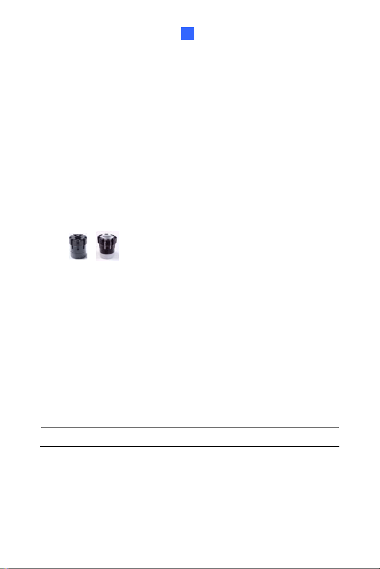
Note: You can choose to run the wires through a conduit pipe. After you
have threaded all the wires, install the supplied conduit converter with a
PG21 conduit connector and a self-prepared conduit pipe (of 1/2’’, 3/4’’
or 1’’) to the camera. Do not use a 1/2’’ pipe if you use the power adapter
for power supply because the adapter cannot be threaded through. A
plastic PG21 conduit connector for 1/2” pipe can be purchased upon
request.
Conduit converter
Plastic PG21
conduit connector
Conduit pipe
50
Target Mini Fixed Rugged Dome
4
4.2 Overview
Figure 4-1
No. Name Description
1 Lens Receives image inputs.
2 Tilt Screw Loosens the screw to adjust tilt angle.
3 Pan Screw Loosens the screw to adjust pan angle.
4
Default
Button
Resets the camera to factory default. For details,
see 4.5 Loading Factory Default.
5 DC 12V Port Connects to power.
6 LAN / PoE Connects to a 10/100 Ethernet or PoE.
a Status Turns on (green) when the system is ready.
b Power Turns on (green) when power is on.
c Link Turns on (green) when the network is connected.
d ACT Turns on (orange) when data are being transmitted.
51
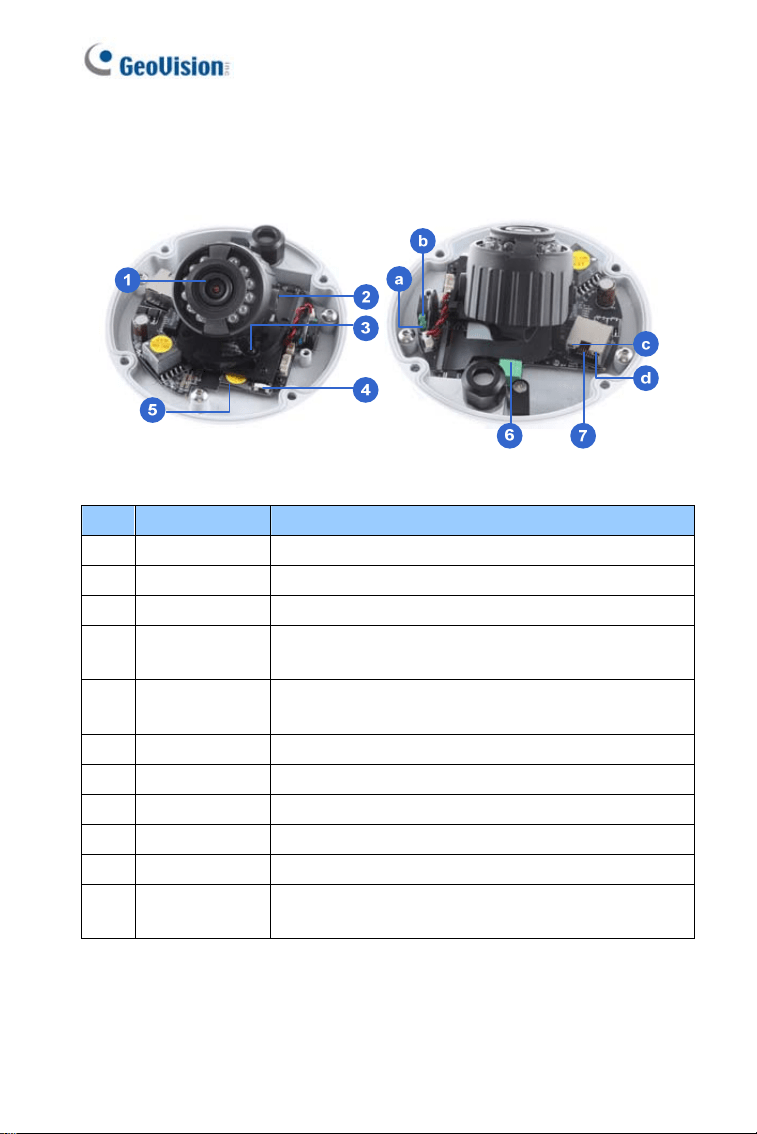
4.2.1 GV-EDR2700
Figure 4-2
No. Name Description
1 Lens Receives image inputs.
2 Tilt Screw Loosens the screw to adjust tilt angle.
3 Pan Screw Loosens the screw to adjust pan angle.
4
Default
Button
Resets the camera to factory default. For details,
see 4.5 Loading Factory Default.
5
Memory Card
Slot
Inserts a micro SD card (SD/SDHC/UHSI, Class
10) to store recording data.
6 DC 12V Port Connects to power.
7 LAN / PoE Connects to a 10/100 Ethernet or PoE.
a Status Turns on (green) when the system is ready.
b Power Turns on (green) when power is on.
c Link Turns on (green) when the network is connected.
d ACT
Turns on (orange) when data are being
transmitted.
52
Target Mini Fixed Rugged Dome
4
4.3 Installation
The Target Mini Fixed Rugged Dome can be installed on the wall or ceiling.
You must use the supplied waterproof rubber set to waterproof the cable.
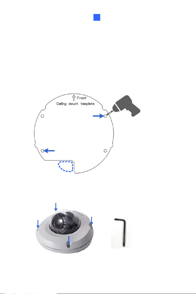
1. Paste the installation sticker where you want to install, and drill two
holes that are at a diagonal. To run the cables inside the wall or
ceiling, drill a larger opening as shown below.
Figure 4-3
2. Insert the supplied screw anchors into the two drilled holes.
3. Open the camera’s housing cover using the supplied torx wrench.
Figure 4-4
53
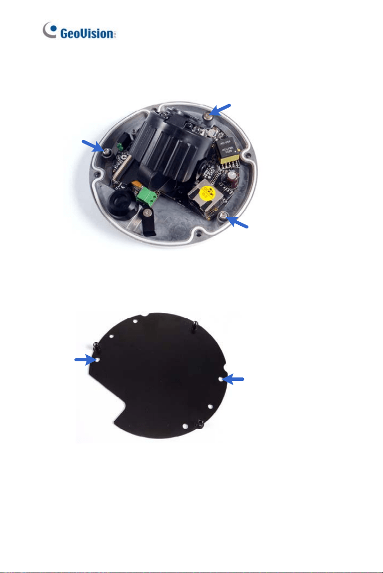
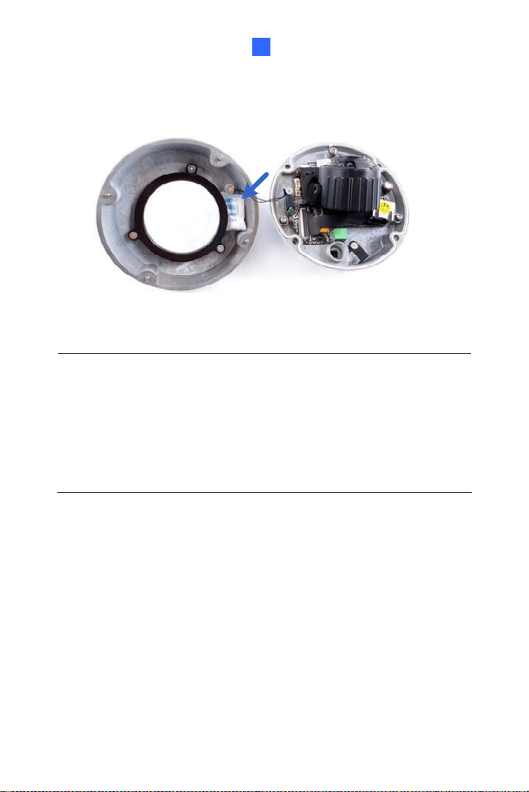
4. Unscrew the three screws as indicated below. A back plate can be
separated from the bottom.
Figure 4-5
5. Use the 2 supplied screws to secure the back plate onto the ceiling or
the wall where the screw anchors were inserted.
Figure 4-6
6. Prepare an Ethernet cable with the RJ-45 connector on one end only.
54
Target Mini Fixed Rugged Dome
4
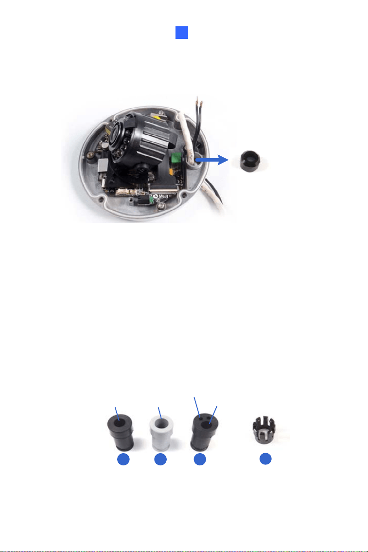
7. Remove the waterproof cap from the cable opening and thread the
power and / or network cable(s) through the opening.
Figure 4-7
8. Install the supplied waterproof rubber set onto the cable(s). The
rubber set has two parts. According to the below situation, replace
Part 1 if necessary.
y For users of PoE with a Cat.5 Ethernet cable, stay with Part 1a
on the camera body.
y For users of PoE with a Cat.6 Ethernet cable, change Part 1a to
the supplied Waterproof rubber set (1b).
y For users of DC 12V, change Part 1a to the supplied Waterproof
rubber set (1c).
2
For adapter wire
For Ethernet cable
For Cat.5 Ethernet
cable (PoE)
For Cat.6 Ethernet
cable (PoE)
1a
1b 1c
Figure 4-8
55
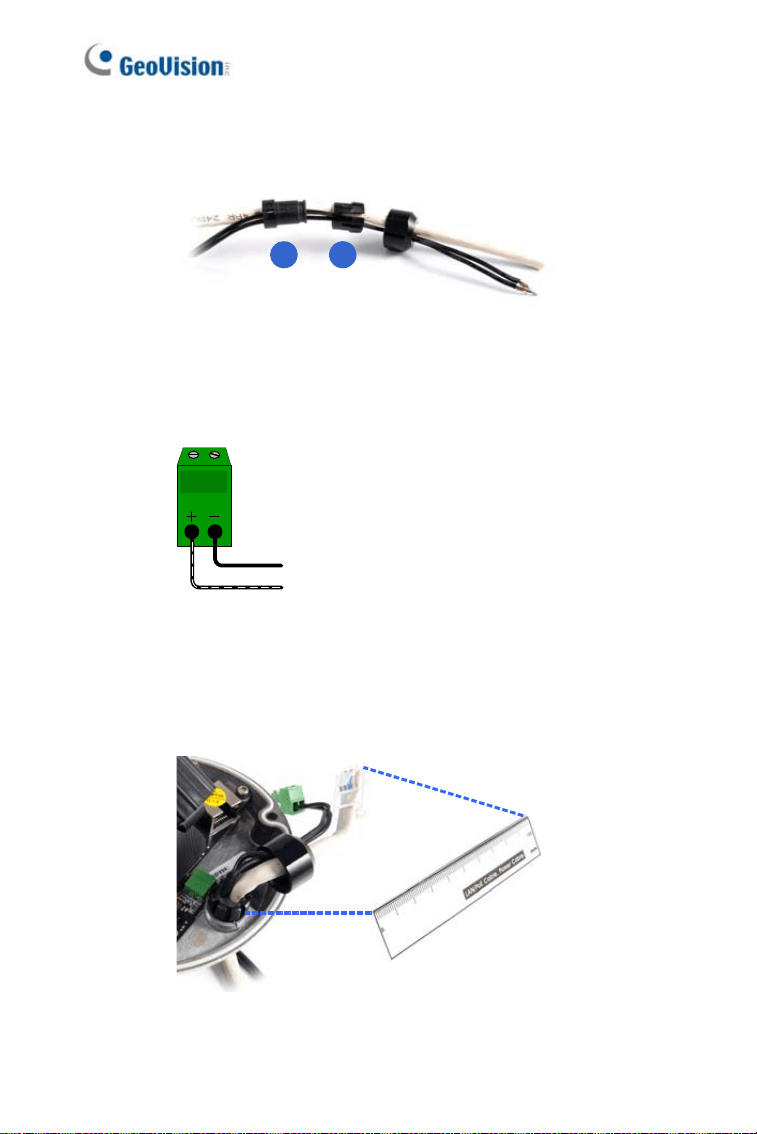
A. Slide the waterproof rubber set, and the waterproof cap you
previously removed through the cable(s) as shown below.
21
Figure 4-9
B. Connect the supplied RJ-45 connector to the Ethernet cable.
C. If you are using a power adapter, insert the striped wire to the
left pin (+) and the other wire to the right pin (-).
Figure 4-10
D. Fit item 1 to item 2, and insert them in the cable opening. Use
the supplied ruler to make sure the length of the cable(s) from
the bottom of the opening to the end of the cable is under
10 cm.
Figure 4-11
56
Target Mini Fixed Rugged Dome
4
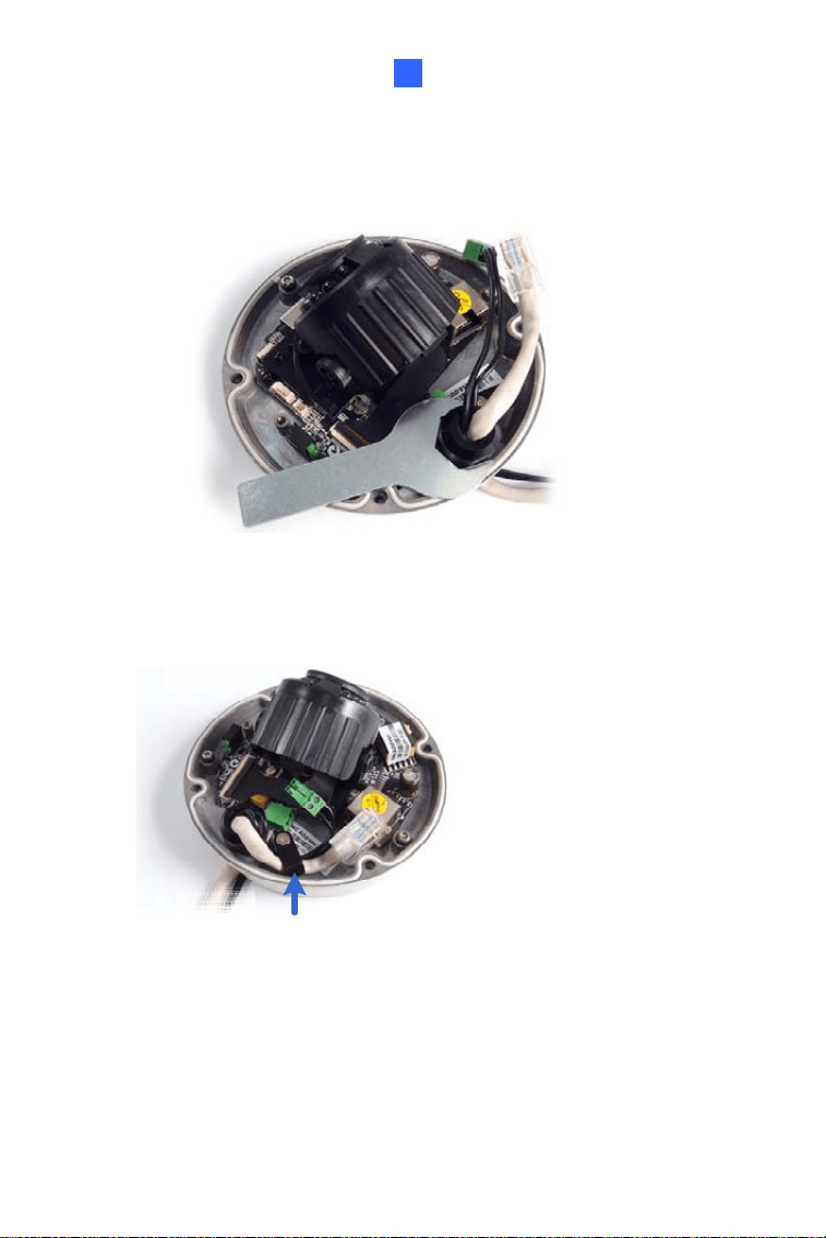
E. Cap the cable opening with the waterproof cap. Use the
supplied concave hexagon wrench to tighten.
Figure 4-12
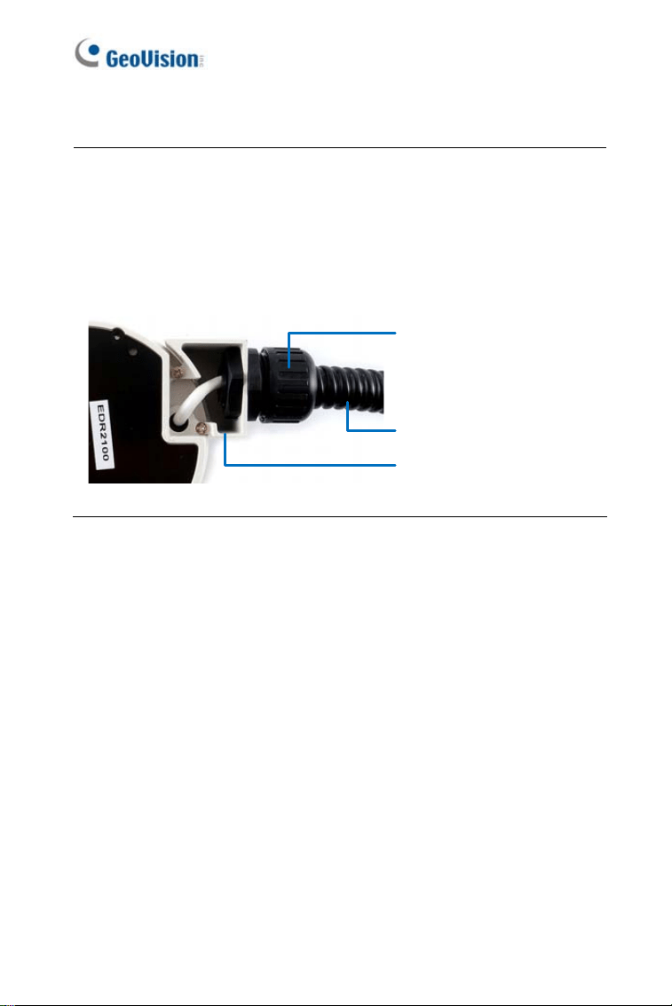
9. Thread the cable(s) under the black cable holder. You can loosen the
screw on the cable holder if needed.
Figure 4-13
10. Connect the camera to network and power. For details, see 4.4
Connecting the Camera.
57
11. Only for GV-EDR2700 series, insert a memory card.
Figure 4-14
12. Secure the camera to the back plate by tightening the three screws as
shown in Step 4.
13. Access the live view. For details, see 7.2 Accessing the Live View.
14. Adjust image clarity using the GV-IP Device Utility program. For
details, see 7.3 Adjusting Image Clarity.
15. Loosen the tile screw and pan screw, adjust the angles based on the
live view as needed, and tighten the screws again.
Figure 4-15
58
Target Mini Fixed Rugged Dome
4
16. Attach the silica gel bag to the place indicated below, and secure the
housing cover using the torx wrench.
Figure 4-16
IMPORTANT:
1. The gel bag loses its effectiveness when the dry camera is
opened. To prevent the lens from fogging up, replace the silica gel
bag every time you open the camera and conceal the silica gel bag
within 2 minutes of exposing to open air.
2. Make sure the housing cover is properly secured to prevent water
from entering and damaging the inner housing.
59
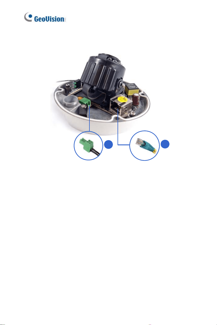
4.4 Connecting the Camera
1
2
Figure 4-17
1. Connect power using one of the following methods:
• Plug the power adapter to the 12V terminal block. The power
adapter is an optional device. For detail, see Options in the
manual.
• Use the Power over Ethernet (PoE) function and the power will be
provided over the network cable.
The power and status LEDs shall turn on (green).
2. Use a standard network cable to connect the camera to your network.
3. You are ready to access the live view, adjust the image clarity and
configure the basics. See Chapter 7, Accessing the Camera.
60
Target Mini Fixed Rugged Dome
4
4.5 Loading Factory Default
4.5.1 Using the Web Interface
You can restore factory default settings through the Web interface. For
details, see 1.5.1 Using the Web Interface.
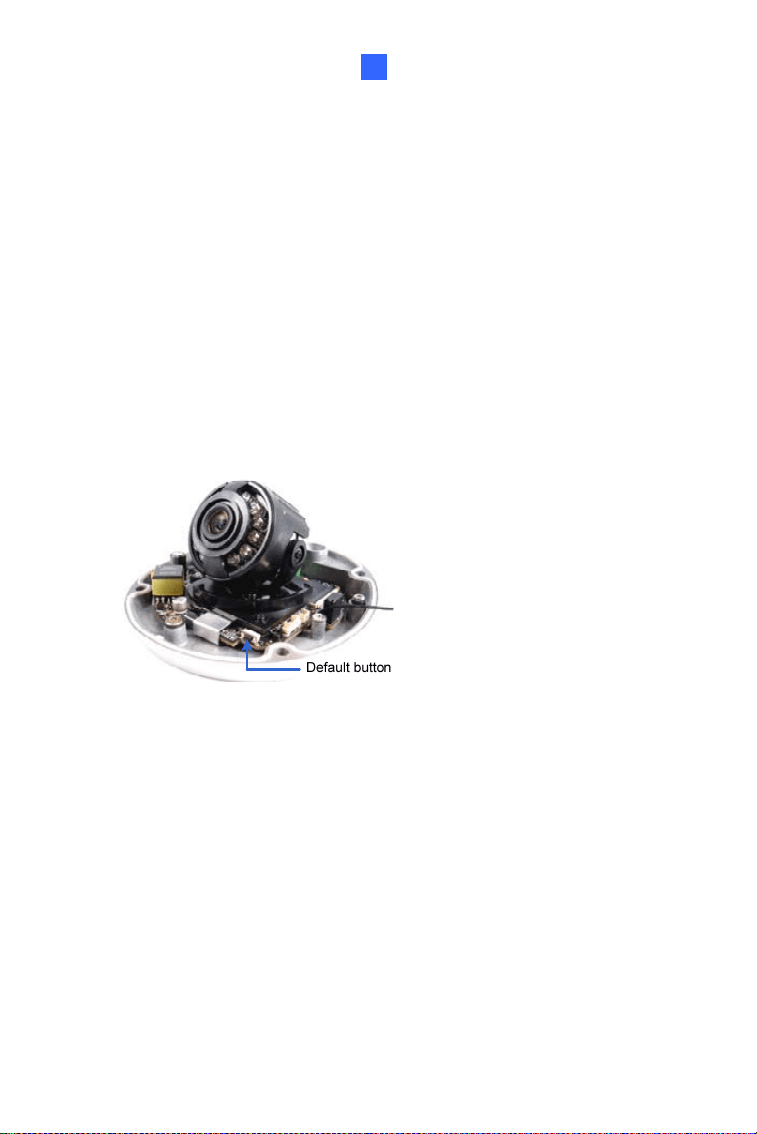
4.5.2 Directly on the Camera
1. Keep the power and network cables (or PoE) connected to the
camera.
2. Press and hold the
default button for about 8 seconds.
Figure 4-18
61
62
3. Release the default button when the status LED blinks.
Figure 4-19
When the
status LED fades, the process of loading default settings is
completed and the camera reboots automatically.
Cube Camera
5
Chapter 5 Cube Camera
The Cube Camera is a light weighted network camera designed for indoor
usage. Its simple design allows for fast and easy installation and fixed-spot
surveillance once installed. Four models are available:
Model No. Specification Description
GV-CB120
1.3 MP, H.264, Cube
Camera
GV-CB220
Fixed
Lens
Fixed Iris, f: 3.35
mm, F/2.4, 1/3”
M12 mm lens
mount
2 MP, H.264, Cube
Camera
63
5.1 Packing List
• Cube Camera
• Supporting Rack
• Screw x 3
• Screw Anchor x 3
• Power Adapter • Download Guide
• Warranty Card
Note: The power adapter can be excluded upon request.
64
Cube Camera
5
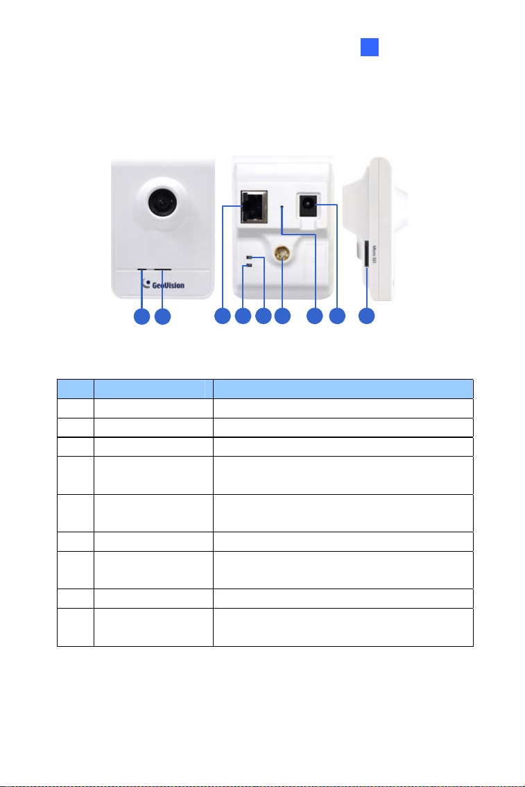
5.2 Overview
1 2
3 4 5 6 7 8 9
Figure 5-1
No. Name Description
1 Microphone Receives sounds.
2 Speaker Plays sounds.
3 LAN Connects to a 10/100 Ethernet.
4 Status LED
Turns red when the system powers on.
Turns orange when the system is ready.
5 LAN LED
Turns green when the camera is connected
to the Internet through wires.
6 Stand screw Connects to the Supporting Rack.
7 Default Button
Resets the camera to factory default. For
details, see 5.5 Loading Factory Default.
8 Power port Connects to the power adapter.
9 Memory Card Slot
Inserts a micro SD card (SD/SDHC, version
2.0 only, Class 10) to store recording data.
65
5.3 Installation
Follow the steps below to install, connect to and adjust your Cube Camera
and Wireless Cube Camera.
1. Put the supporting rack on the desired location and make marks for
screw anchors.
Figure 5-2
2. Drill the marks and insert the screw anchors.
3. Secure the supporting rack onto the wall using the supplied screws.
4. Screw the camera onto the supporting rack and fasten the indicated
screw.
Figure 5-3
66
Cube Camera
5
5. Connect the network and power cables to the camera. See 5.4
Connecting the Camera.
6. Access the live view. See 7.2 Accessing the Live View.
7. Adjust the angle of the camera based on live view and fasten the
indicated screw.
Figure 5-4
67
5.4 Connecting the Camera
1
2
Figure 5-5
1. Use a standard network cable to connect the camera to your network.
2. Power on using the power adapter.
3. The status LED of the camera will be orange.
IMPORTANT: Be sure to use the GeoVision power adapter to power up
the camera. To use your own power cable, make sure you look up the
power source value indicated at the camera’s back panel.
68
Cube Camera
69
5
5.5 Loading Factory Default
5.5.1 Using the Web Interface
You can restore factory default settings through the Web interface. For
details, see 1.5.1 Using the Web Interface.
5.5.2 Directly on the Camera
1. Keep the power and network cables connected to the camera.
2. Use a pin to press and hold the
default button on the panel.
Status LED
Default button
Figure 5-6
3. Release the default button when the status LED blinks. This shall
take about 8 seconds.
4. When the
status LED turns orange, the process of loading default
settings is completed and the camera is ready for use.
Chapter 6 Advanced Cube
Camera
The Advanced Cube Camera integrates the passive infrared (PIR) sensor
and the alarm LED to illuminate the scene automatically when the motion is
detected. It also offers wireless connection to the network for flexible
installation. It is small, light, and easy-to-use for indoor security. We
provide four models:
Model No. Specification Description
GV-CA120
1.3 MP, H.264,
Cube Camera
GV-CA220
2 MP, H.264, Cube
Camera
GV-CAW120
1.3 MP, H.264,
Wireless Cube
Camera
GV-CAW220
Fixed
Lens
Fixed Iris, f: 3.35
mm, F/2.4, 1/3” M12
mm lens mount
2 MP, H.264,
Wireless Cube
Camera
70
Advanced Cube Camera
6
6.1 Packing List
• Advanced Cube Camera
• Supporting Rack
• Screw x 3
• Screw Anchor x 3
• Power Adapter • Download Guide
• Warranty Card
Note: The power adapter can be excluded upon request.
71
6.2 Overview
1 2 3 4 5 6 7 8 9 10 11
12
13
Figure 6-1
No. Name Description
1 Speaker
Plays sounds for tampering and motion
alarm, and listens to the audio around the
camera. To set up alarm sound, see 4.3.9
Speaker, GV-IPCam Firmware Manual.
2 PIR sensor Passive infrared sensor.
3 Microphone Receives sounds.
4
White Illumination
LED
When the PIR sensor detects the
movement, the white illumination LED
lights up in a low light scene. To set up the
LED, see 4.1.1 Video Settings, GV-IPCam
Firmware Manual.
5 Monitoring LED
Reflects monitoring status of the camera.
See the below table.
6 Live View LED
Reflects live view status of the camera.
See the below table.
7 LAN / PoE Connects to a 10/100 Ethernet or PoE.
72
Advanced Cube Camera
6
No. Name Description
8 Stand screw Connects to the Supporting Rack.
9 Power port Connects to the power adapter.
10 Ready LED
Reflects system status of the camera. See
the below table.
11 LAN LED
Reflects LAN status of the camera. See the
below table.
12 Memory Card Slot
Inserts a micro SD card (SD/SDHC,
version 2.0 only, Class 10) to store
recording data.
13 Default
Resets the camera to factory default. For
details, see 6.5 Loading Factory Default.
IMPORTANT: The White Illumination LED can reach high temperatures.
Be sure not to touch the LED with bare hand.
LED Status Description
Live View
• Turns on orange light when you
see the live view.
Monitoring
• Turns on red light when you start
monitoring.
Ready
• Turns on green light when the
system is ready.
• Flashes green light when you
load default value.
LAN
• Turns on green light when you
connect the LAN Network.
• Turns on blue light when you
connect the Wi-Fi Network (for GV-
CAW120 / 220 only).
73
6.3 Installation
Follow the steps below to install, connect to and adjust your Advanced
Cube Camera and Wireless Advanced Cube Camera.
1. Put the supporting rack on the desired location and make marks for
screw anchors.
Figure 6-2
2. Drill the marks and insert the screw anchors.
3. Secure the supporting rack onto the wall using the supplied screws.
4. Screw the camera onto the supporting rack and fasten the indicated
screw.
Figure 6-3
74
Advanced Cube Camera
6
5. Connect the network and power cables to the camera. See 6.4
Connecting the Camera.
6. Access the live view. See 7.2 Accessing the Live View.
7. Adjust the angle of the camera based on live view and fasten the
indicated screw.
Figure 6-4
8. For GV-CAW120/220, to connect to the Internet through wireless
service, follow the steps in 7.2.3 Configuring the Wireless Connection.
75
6.4 Connecting the Camera
1
2
Figure 6-5
1. Use a standard network cable to connect the camera to your network.
2. Connect power using one of the following methods:
• plugging the power adapter to the power port.
• using the Power over Ethernet (PoE) function and the power will be
provided over the network cable.
3. When the ready LED of the camera shines green, the camera is ready
for use.
Note: PoE function is only supported for GV-CA120 and GV-CA220.
76
Advanced Cube Camera
77
6
6.5 Loading Factory Default
6.5.1 Using the Web Interface
You can restore factory default settings through the Web interface. For
details, see 1.5.1 Using the Web Interface.
6.5.2 Directly on the Camera
1. Keep the power and network cables connected to the camera.
2. Use a pin to press and hold the
default button on the panel.
Status LED
Default button
Figure 6-6
3. Release the default button when the status LED blinks. This shall
take about 8 seconds.
4. When the
status LED turns green, the process of loading default
settings is completed and the camera is ready for use.

Chapter 7 Accessing the Camera
7.1 System Requirement
To access the GV-IP Camera through the Web browser, ensure your PC
connects to the network properly and meets this system requirement:
y Microsoft Internet Explorer 8.0 or later
Note: For the users of Internet Explorer 8, additional settings are
required. For details, see Appendix A in GV-IPCAM Firmware Manual.
78

Accessing the Camera
7
7.2 Accessing the Live View
When the camera is connected to a network with a DHCP server, it will be
automatically assigned with a dynamic IP address. See 7.2.1 Checking the
Dynamic IP Address to look up this IP address.
However, if you do not have a DHCP server on your network, access the
camera by its default IP address
192.168.0.10 and see 7.2.2 Configuring
the IP Address for more detail.
79
7.2.1 Checking the Dynamic IP Address
Follow the steps below to look up the IP address and access the Web
interface.
Note:
1. The computer you use to configure the IP address must be under
the same LAN with your camera.
2. The default Administrator and Guest accounts are no longer
supported by
GV-IPCam H.265 series firmware V1.14 or later.
When logging in for the first time, you need to set up a login
username and password for the camera. See Creating GV-IP
Camera’s Login Credentials at the beginning of the quick start
guide.
1. Install
GV-IP Device Utility from the company website.
2. On the GV-IP Utility window, click the
button to search for the IP
devices connected in the same LAN. Click the
Name or Mac Address
column to sort.
80
Accessing the Camera
7
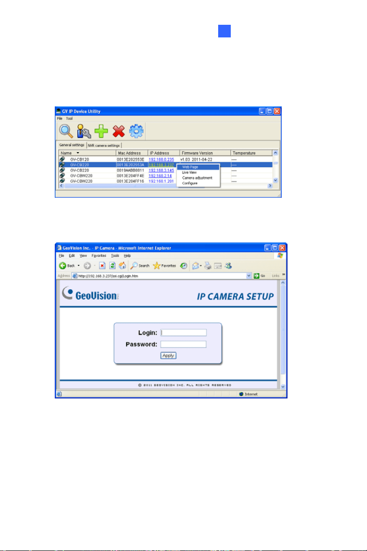
3. Find the camera with its Mac Address, click on its IP address and
select
Web Page
Figure 7-1
4. The login page appears.
Figure 7-2
5. Type the default ID and password
admin and click Apply to log in.
81
7.2.2 Configuring the IP Address
Follow the steps below to configure the IP address.
1. Open your Web browser, and type the default IP address
http://192.168.0.10.
2. In both Login and Password fields, type the default value
admin. Click
Apply.
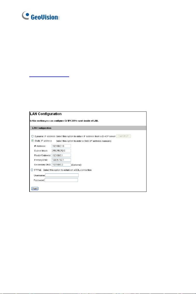
3. In the left menu, select
Network and then LAN to begin the network
settings.
Figure 7-3
4. Select Static IP address, Dynamic IP address or PPPoE and type
the required network information.
5. Click
Apply. The camera is now accessible by entering the assigned
IP address on the Web browser.
6. To enable the updating of images in Microsoft Internet Explorer, you
must set your browser to allow ActiveX Controls and perform a one-
time installation of GeoVision’s ActiveX component onto your computer.
82

Accessing the Camera
7
IMPORTANT:
1. If
Dynamic IP Address or PPPoE is enabled, you need to know
which IP address the camera will get from DHCP server or ISP to
log in. If your camera is installed in the LAN, use the GV-IP Device
Utility to look up its current dynamic IP address. See 7.2.1
Checking the Dynamic IP Address. If your camera uses a public
dynamic IP address via PPPoE, use the dynamic DNS Service to
obtain a domain name that is linked to the camera’s changing IP
address first. For details, see LAN Configuration and Advanced
TCP/IP sections, Administrator Mode Chapter in the GV-IPCAM
Firmware Manual.
2. If
Dynamic IP Address or PPPoE is enabled and you cannot
access the camera, you may have to reset the camera to its
factory default and then perform the network settings again. To
restore factory settings, see 1.5 Loading Factory Default.
83
7.2.3 Configuring the Wireless Connection
You may create wireless connection to the Internet for GV-MFD1501
Series / 2401 series / 3401 series / 5301 series.
1. To set up the wireless LAN for the first time, power on and connect a
standard network cable to the camera.
2. An IP address will be automatically assigned to the camera. Use GV IP
Device Utility to search for the device. For details, see 7.2.1 Checking
the Dynamic IP Address.
3. Configure the wireless settings.
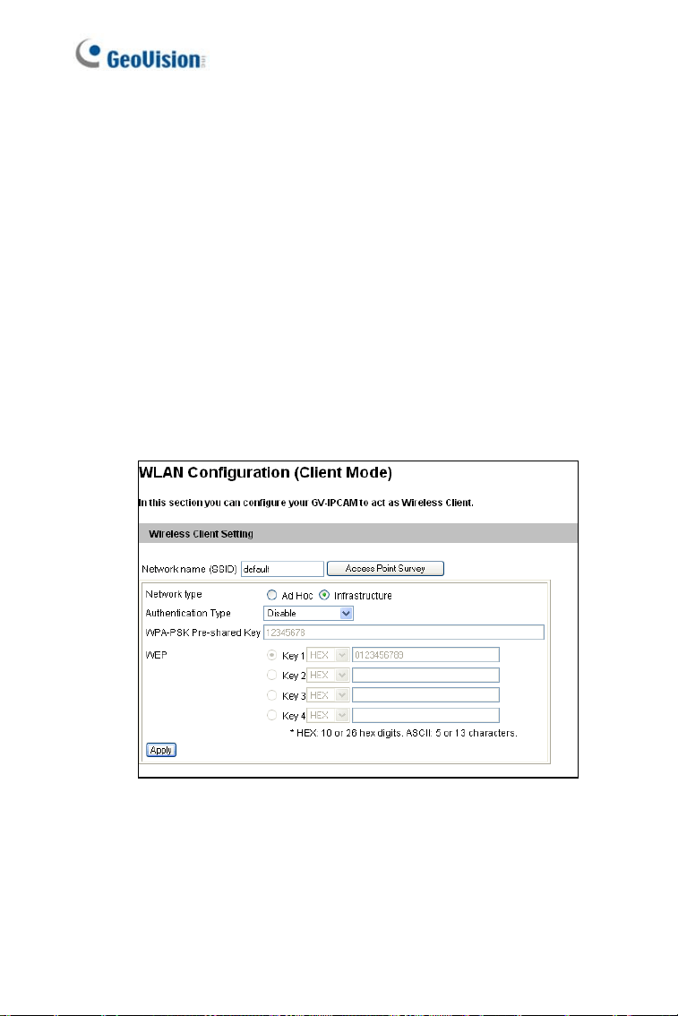
A. On the Web interface, select
Network, select Wireless and
Client Mode. This dialog box appears.
Figure 7-4
B. Type the Network Name (SSID) or click the Access Point
Survey
button to search and select for the available Access
Points/wireless stations.
84

Accessing the Camera
7
C. Select Ad-Hoc or Infrastructure for the Network type.
D. Select the
Authentication Type using the drop-down list. You
can also obtain this information by clicking the
Access Point
Survey
button.
E. Type the
WPA-PSK Pre-shared Key or WEP depending on the
encryption setting for the Access Point.
F. Click
Apply to save the configuration.
Note:
1. Your encryption settings must match those used by the Access
Points or wireless stations with which you want to associate.
2. When
Ad Hoc is used, only WEP encryption is supported.
3. When you lose the wireless access, you can still access the unit by
connecting it to a LAN and using the GV IP Device Utility to search
for the device.
85
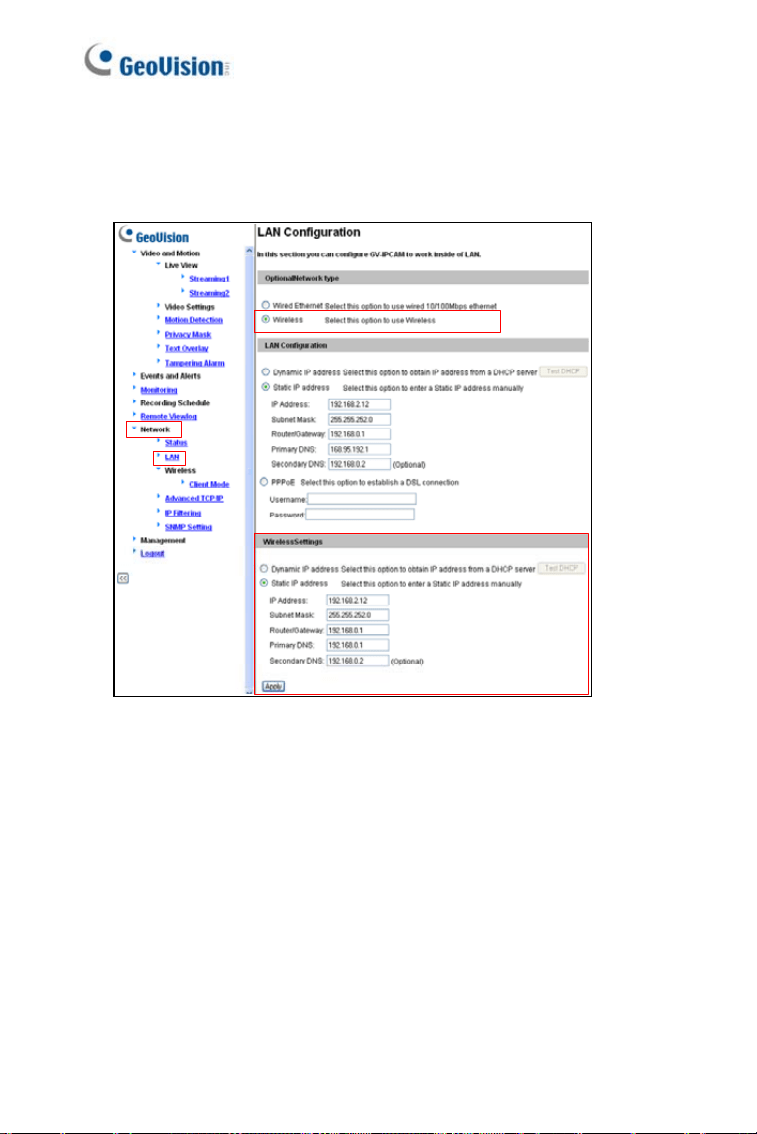
4. Enable wireless LAN.
A. On the Web interface, select
Network and LAN. This page
appears.
Figure 7-5
B. Select Wireless for Optional Network Type.
C. To use a dynamic IP address assigned by the DHCP server,
select
Dynamic IP address. To use a fixed IP address, select
Static IP address and type the IP address information.
5. Click
Apply. The camera will start creating a wireless connection to the
access point.
6. Unplug the Ethernet cable.
86
Accessing the Camera
7
7.3 Adjusting Image Clarity
You can adjust the image clarity using the GV-IP Device Utility. Make sure
that you have connected your GV-IPCAM to the network and install the
GV-IP Device Utility program under the same LAN.
1. Make sure you have installed the GV-IP Device Utility program from
the company website.
2. On the GV-IP Utility window, click the
button to search for the IP
devices connected in the same LAN. Click the IP Address of the
camera you desire. A drop-down list appears.
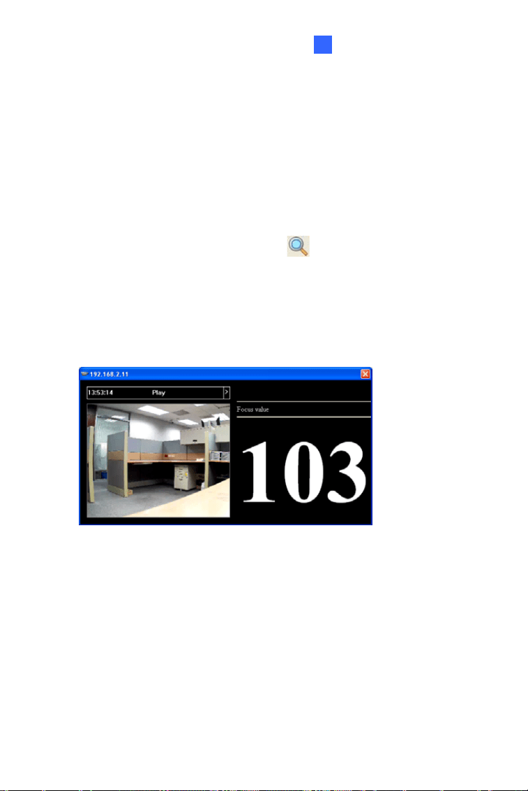
3. Select
Focus Value. The Login dialog box appears.
4. Type the user name and password of the camera selected. The default
is
admin for both user name and password. This window appears.
Figure 7-6
87
88
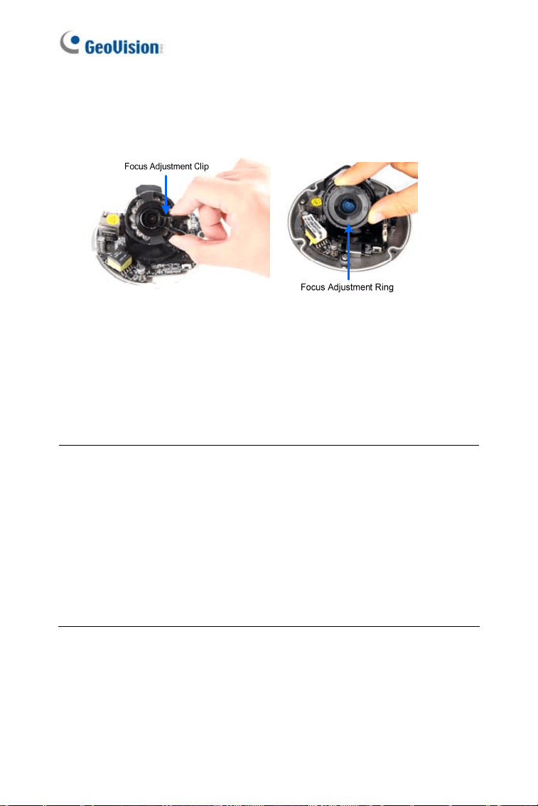
5. For Target Mini Fixed Dome and Target Mini Fixed Rugged Dome,
hold the camera cover close to the lens and use the supplied focus
adjustment tool for precise focus adjustment.
Figure 7-7
6. For
Mini Fixed Dome and Mini Fixed Rugged Dome, hold the
camera cover close to the lens for precise focus adjustment.
7. Adjust the
Zoom Screw and the Focus Screw of the camera slowly
until the focus value reaches the maximum.
Note:
1. For locations of adjustment screws and rings in each model, see
Locations of Adjustment Screws, section, Getting Started Chapter,
GV-IPCAM Firmware Manual.
2. Do not over tighten the screws. The screws only need to be as
tight as your fingers can get them to be. Do not bother using any
tool to get them tighter. Doing so can damage the structure of lens.
3. The maximum focus value may vary when the environment
changes.
The Web Interface
8
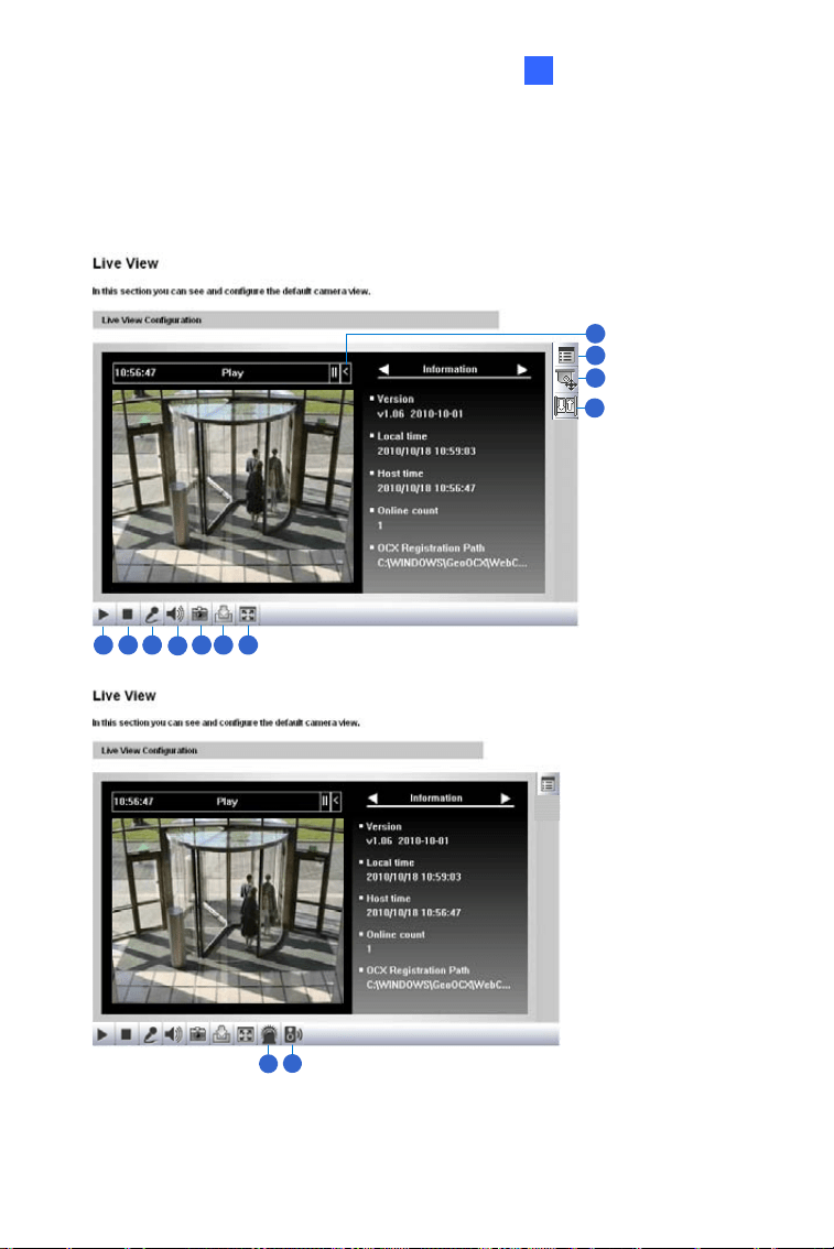
Chapter 8 The Web Interface
1 2 3
4
5 6 7
8
9
10
11
12
13
Figure 8-1
89

No. Name Function
1 Play Plays live video.
2 Stop Stops playing video.
3 Microphone
Broadcasts to the surveillance site from a remote
PC. Note this function is not available for
Ultra
Bullet Camera
and Target Series. For Cube
Camera
and Advanced Cube Camera, click the
Push to talk button (from the pop-up menu) for the
camera to switch between audio transmission and
reception, where only one party can speak at a
time.
4 Speaker
Transfers sounds of the surveillance site to a
remote PC. Note this function is not available for,
Mini Fixed Rugged Dome, Ultra Bullet Camera,
Target Bullet Camera, and Target Mini Fixed
Rugged Dome
.
5 Snapshot Takes a snapshot of live video.
6 File Save Records live video to the local computer.
7 Full Screen
Switches to full screen view. Right-click the image
to see additional options.
8 Control Panel
Displays the camera information, video settings,
audio data rate, I/O device status, images captured
upon alarm, and GPS location of the camera. Also
allows you to adjust image quality and install the
program from the hard drive.
9
Show System
Menu
Brings up these functions: Alarm Notify, Video and
Audio Configuration, Remote Config, Show
Camera Name and Image Enhance.
90

The Web Interface
91
8
No. Name Function
10
PTZ Control
Panel
Enables the PTZ Control Panel or the Visual PTZ.
Note this function is supported by
PTZ Camera
and
PT Camera, and only partially supported by
GV-IP Cameras with motorized varifocal lens.
11 I/O Control
Enables the I/O Control Panel and Visual
Automation. Note this function is not available in
Mini Fixed Dome, Mini Fixed Rugged Dome,
Cube Camera, Advanced Cube Camera and
Target Series.
12 LED Control
Click to turn the Alarm LED on and/or adjust the
brightness sensitivity. Note this function is only
available for
Advanced Cube Camera.
13
Alarm
Speaker
Click to sound the alarm and/or adjust its volume.
To sound the alarm upon motion or tampering
events, see Speaker section, Administrator Mode
Chapter, GV-IPCAM Firmware Manual. Note this
function is only available for
Advanced Cube
Camera
.

Chapter 9 Upgrading System
Firmware
GeoVision periodically releases updated firmware on the website. The new
firmware can be simply loaded into the GV-IPCAM by using the Web
interface or IP Device Utility.
Before you start
z If you use the IP Device Utility for firmware upgrade, the computer
used to upgrade firmware must be under the same network of the
camera.
z Stop monitoring of the camera.
z Stop all remote connections, such as GV-VMS.
z While the firmware is being updated, the power supply must not be
interrupted.
WARNING: The interruption of power supply during updating causes
not only update failures but also damages to the camera. In this case,
please contact your sales representative and send your device back to
GeoVision for repair.
z Do not turn the power off within 10 minutes after the firmware is
updated.
92
Upgrading System Firmware
93
9
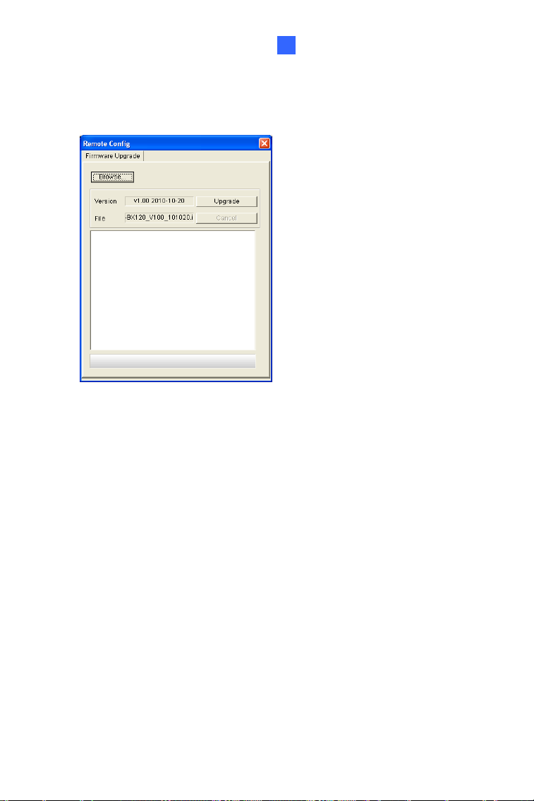
1. In the Live View window, click the Show System Menu button and
select
Remote Config. This dialog box appears.
Figure 9-1
2. Click the Browse button to locate the firmware file (.img) saved at your
local computer.
3. Click the
Upgrade button to start the upgrade.