THIS INSTRUCTION BOOKLET CONTAINS IMPORTANT SAFETY INFORMATION. PLEASE READ AND KEEP FOR FUTURE REFERENCE.
EN DE FR ES IT PL
USER'S MANUAL/HANDBUCH
/MANUEL DE L'UTILISATEUR/MANUAL DEL USUARIO
/MANUALE UTENTE/INSTRUKCJA OBSŁUGI
SP37608
Golf Push Cart / Golftrolley / Chariot de Golf /
Carrito de Golf / Carrello da Golf / Wózek golfowy
02
Warning:
For your own safety, please read and understand
these warnings and keep this user guide for future
reference.
Always make sure the cart is fully extended and
locked before use.
Always make sure the cart is folded and locked
properly before lifting or transporting.
Do not run while using this product.
Do not use accessories other than those designed
for use with this cart.
Keep all packing materials away from children and
recycle where possible or where required by law.
EN
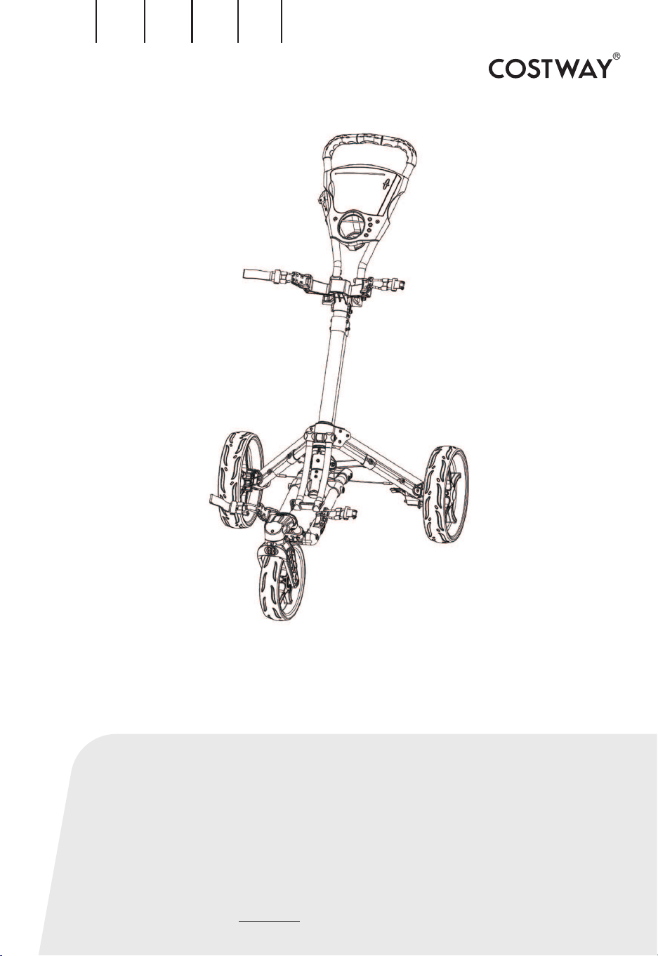
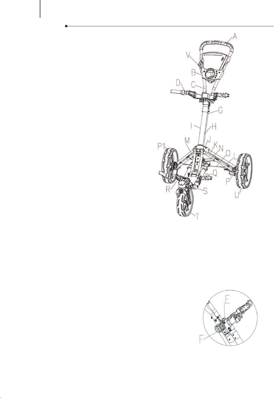
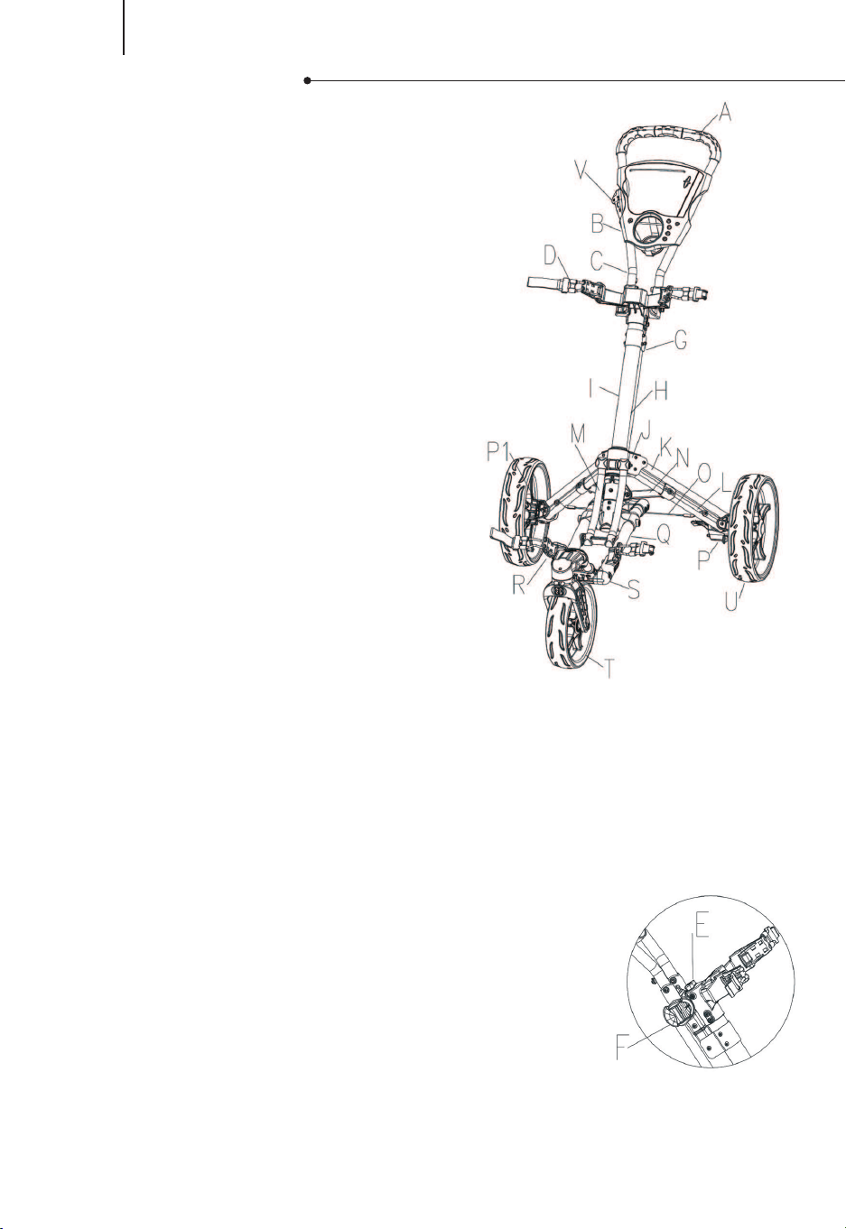
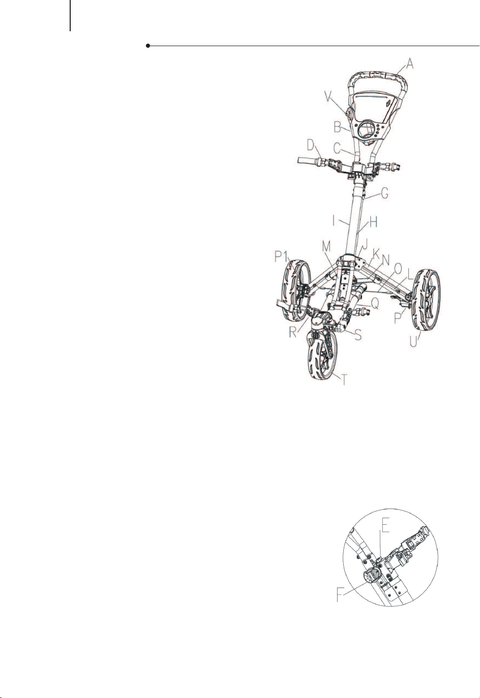
PARTS LIST
MAINTENANCE
To clean the cart, wipe with a soft, dry cloth. Car polish may be used to
maintain finish. Lubricate moving parts every 6 months.
A Hand grip
B Scorecard holder
C Handle tube
D Upper bag holder bracket
E Push button system
F Adjustable handle mechanism
G Joint
H Connecting rods
I Main upper frame tube
J Leg bracket
K 2 holes leg frame
L 4 holes leg frame
M Slippery connecting rods
N Weight stabilizer
O Anti-splay wire
P Right wheel locking mechanism
P1 Left wheel locking mechanism
Q Main lower frame tube
R Adjustable bag elastic rope
S Lower bag holder bracket
T Front wheel assembly
U Main wheel
V Handle brake for front wheel swivel
03
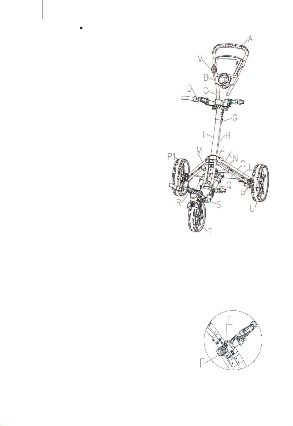
Pull the handle
up until you hear
the cart 'Click' as
in Fig.1.
Press the button and
insert the rear wheels
as in Fig.2.
Insert the front wheel
as in Fig.3.
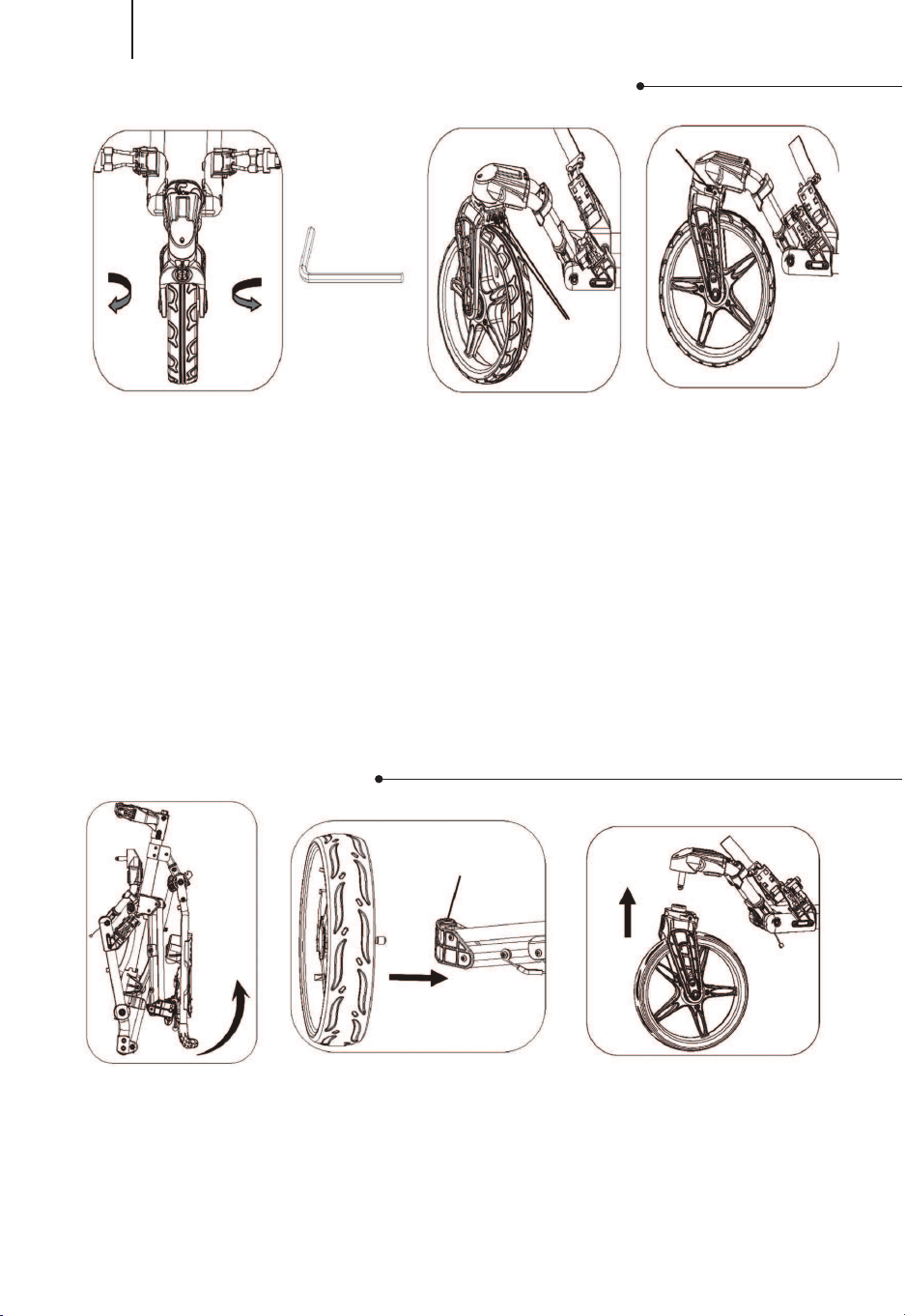
When facing the cart:
If the cart veers to RIGHT: use the Allen wrench(as shown in Fig. 3) to losen
the 2 screws (A) on the backside of the front wheel frame as shown in Fig. 4.
Then adjust the front wheel to center position by turning the screw (B)
counterclockwise as in Fig. 3. Tighten the 2 Screws (A) after the front wheel
alignment is done.
If the cart veers to LEFT: use the Allen wrench(as shown in Fig. 3) to losen
the 2 screws (A) on the backside of the front wheel frame as shown in Fig. 4.
Then adjust the front wheel to center position by turning the screw (B)
clockwise as in Fig. 3. Tighten the 2 Screws (A) after the front wheel alignment
is done.
FRONT WHEEL ALIGNMENT
UNFOLDING
EN
Left Right
Allen wrench
Fig.1
Fig.1
Fig.2
Button
Fig.2
Fig.3
Fig.3
A
B
Fig.4

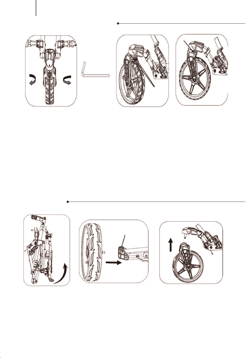
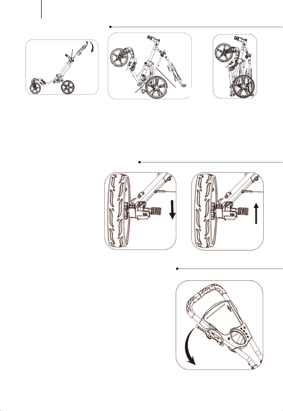
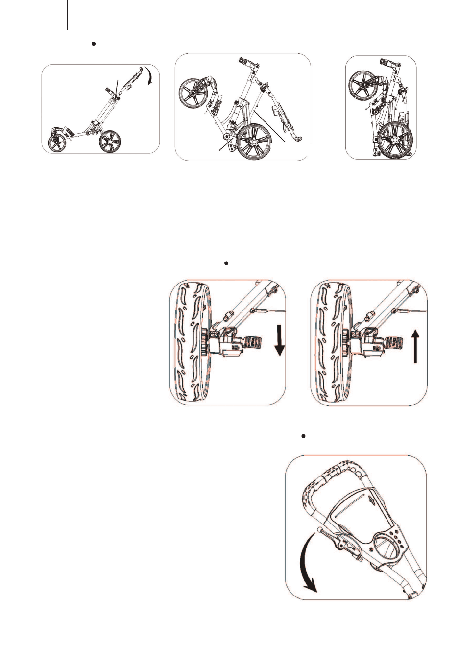
Press the button
and fold the cart
in the direction of
the arrow as in
Fig.4.
As shown in Figure 9, the front wheel
can rotate 360 degrees when the
handbrake is pulled down, and then
the handbrake is pulled up, and the
front wheel will travel in a straight line.
Push on the brake
pedal to stop the
rear wheel and pull
off to release as in
Fig.7 & 8.
The connecting rod will insert into the plastic
bracket when folding is completed as Fig. 5/6.
04
EN
USE THE BRAKE
SWIVEL FRONT WHEEL SYSTEM
FOLDING
Button
Fig.4
Fig.7 Fig.8
Fig.9
Fig.5
holding
slot
connecting rod
Fig.6
Teileliste
05
DE
Warnung:
Bitte lesen Sie zu Ihrer eigenen Sicherheit diese
Warnhinweise aufmerksam durch und bewahren Sie diese
Bedienungsanleitung zum späteren Nachschlagen auf.
Vergewissern Sie sich vor der Benutzung immer, dass der
Trolley vollständig ausgefahren und verriegelt ist.
Vergewissern Sie sich immer, dass der Trolley vor dem
Anheben oder Transportieren ordnungsgemäß
zusammengeklappt und verriegelt ist.
Laufen Sie nicht, während Sie dieses Produkt benutzen.
Verwenden Sie nur Zubehör, das für die Verwendung mit
Ihrem Trolley vorgesehen ist.
Bewahren Sie sämtliches Verpackungsmaterial außerhalb
der Reichweite von Kindern auf und recyceln Sie es, sofern
möglich oder gesetzlich vorgeschrieben.
WARTUNG
Wischen Sie den Trolley mit einem weichen, trockenen Tuch ab, um ihn zu
reinigen. Zur Pflege der Oberfläche kann eine Autopolitur verwendet werden.
Schmieren Sie bewegliche Teile alle 6 Monate.
A Handgriff
B Scorekartenhalter
C Handgriffrohr
D Obere Taschenhalterung
E Druckknopfsystem
F Verstellbarer Griffmechanismus
G Gelenk
H Verbindungsstangen
I Oberes Hauptrahmenrohr
J Beinhalterung
K 2-Loch-Beinrahmen
L 4-Loch-Beinrahmen
M Gleitende Verbindungsstangen
N Gewichtsstabilisator
O Anti-Spanndraht
P Verriegelungsmechanismus des rechten Rades
P1 Verriegelungsmechanismus des linken Rades
Q Unteres Hauptrahmenrohr
R Gummiseil für verstellbare Tasche
S Untere Taschenhalterung
T Vorderrad-Baugruppe
U Hauptrad
V Griffbremse für Vorderradschwenkung

06
DE
Ziehen Sie den
Griff nach oben,
bis Sie den
Wagen "klicken"
hören, wie in
Abb.1.
Drücken Sie den
Knopf und setzen Sie
die Hinterräder wie in
Abb.2 ein.
Setzen Sie das
Vorderrad wie in
Abb.3 ein.
Mit dem Gesicht zum Wagen
Wenn der Wagen nach RECHTS kippt: Verwenden Sie den Inbusschlüssel
(wie in Abb. 3 gezeigt), um die 2 Schrauben (A) auf der Rückseite des
Vorderradrahmens zu lösen, wie in Abb. 4 gezeigt. Drehen Sie dann die
Schraube (B) gegen den Uhrzeigersinn, wie in Abb. 3 gezeigt, um das
Vorderrad in die Mittelposition zu bringen. Ziehen Sie die 2 Schrauben (A) fest,
nachdem Sie das Vorderrad ausgerichtet haben.
Wenn der Wagen nach LINKS kippt: Verwenden Sie den Inbusschlüssel (wie
in Abb. 3 gezeigt), um die 2 Schrauben (A) auf der Rückseite des
Vorderradrahmens zu lösen, wie in Abb. 4 gezeigt. Drehen Sie dann die
Schraube (B) im Uhrzeigersinn, wie in Abb. 3 gezeigt, um das Vorderrad in die
mittlere Position zu bringen. Ziehen Sie die 2 Schrauben (A) nach dem
Ausrichten des Vorderrads wieder fest.
AUSRICHTUNG DES VORDERRADS
Aufklappen
Links Rechts
Inbusschlüssel
Abb. 1
Abb. 1
Abb. 2
Knopf
Abb. 2
Abb. 3
Abb. 3
A
B
Abb. 4
07
DE
Drücken Sie den Knopf
und klappen Sie den
Wagen in Pfeilrichtung
zusammen, wie in
Abb.4 dargestellt.
Wie in Abb. 9 gezeigt, kann das
Vorderrad um 360 Grad gedreht
werden, wenn die Handbremse
angezogen ist, und wenn die
Handbremse angezogen ist, fährt das
Betätigen Sie das
Bremspedal, um das
Hinterrad anzuhalten,
und heben Sie das
Bremspedal an, um
das Hinterrad zu
lösen.
Die Verbindungsstange wird in die
Kunststoffhalterung eingeführt, wenn das
Zusammenklappen abgeschlossen ist (Abb. 5/6).
BENUTZEN SIE DIE BREMSE
SCHWENKBARES VORDERRADSYSTEM
ZUSAMMENKLAPPEN
Knopf
Abb. 4
Abb. 7 Abb. 8
Abb. 9
Abb. 5
Halteschlitz
Verbindungsstange
Abb. 6
08
FR
LISTE DES PIÈCES
Avertissement :
Pour votre propre sécurité, veuillez lire et comprendre ces
avertissements et conserver ce guide de l'utilisateur pour
référence future.
Assurez-vous toujours que le chariot est complètement
étendu et verrouillé avant utilisation.
Assurez-vous toujours que le chariot est correctement plié
et verrouillé avant de le soulever ou de le transporter.
Ne courez pas pendant l'utilisation de ce produit.
N'utilisez pas d'accessoires autres que ceux conçus pour
être utilisés avec ce chariot.
Gardez tous les matériaux d'emballage hors de portée des
enfants et recyclez-les si possible ou si la loi l'exige.
MAINTENANCE
Pour nettoyer le chariot, essuyez-le avec un chiffon doux et sec. Le polish
automobile peut être utilisé pour entretenir la finition. Lubrifiez les pièces
mobiles tous les 6 mois.
A. Poignée
B. Support de marqueur
C. Tube de poignée
D. Porte-sac supérieur
E. Système de bouton poussoir
F. Mécanisme de poignée ajustable
G. Jonction
H. Bielles
I. Tube principal du cadre supérieur
J. Support de pied
K. Piétement avec 2 trous
L. Piétement avec 4 trous
M. Bielles glissantes
N. Stabilisateur de poids
O. Fil anti-basculement
P. Mécanisme de blocage de la roue droite
P1. Mécanisme de blocage de la roue gauche
Q. Tube principal inférieur du châssis
R. Cordon élastique ajustable pour le sac
S. Support de sac inférieur
T. Assemblage des roues avant
U. Roue principale
V. Frein de poignée pour la rotation de la roue avant

09
FR
Tirez la poignée
vers le haut
jusqu'à ce que
vous entendiez le
"clic" du chariot,
comme indiqué
sur l’image 1.
Appuyez sur le
bouton et insérez les
roues arrière comme
indiqué sur l’image 2.
Insérez la roue avant
comme indiqué sur
l’image 3.
Face au chariot :
Si le chariot dérive vers la DROITE : Utilisez la clé Allen (comme indiqué sur
l’image 3) pour desserrer les 2 vis (A) à l'arrière du cadre de la roue avant,
comme indiqué sur l’image 4. Ensuite, réglez la roue avant en position centrale
en tournant la vis (B) dans le sens antihoraire comme indiqué sur l’image 3.
Serrez les 2 vis (A) après l'alignement des roues avant.
Si le chariot dérive vers la GAUCHE : Utilisez la clé Allen (comme indiqué
sur l’image 3) pour desserrer les 2 vis (A) à l'arrière du cadre de la roue avant,
comme indiqué sur l’image 4. Ensuite, réglez la roue avant en position centrale
en tournant la vis (B) dans le sens des aiguilles d'une montre, comme indiqué
sur l’image 3. Serrez les 2 vis (A) après l'alignement des roues avant.
ALIGNEMENT DES ROUES AVANT
EXTENSION
Gauche Droit
Clé Allen
Image 1
Image 1
Image 2
Bouton
Image 2
Image 3
Image 3
A
B
Image 4
10
FR
Appuyez sur le bouton
et pliez le chariot dans
le sens de la flèche
comme indiqué sur
l’image 4.
Comme indiqué sur l’image 9, la roue
avant peut tourner à 360 degrés
lorsque le frein à main est tiré vers le
bas, puis le frein à main est tiré vers le
haut et la roue avant se déplacera en
ligne droite.
Appuyez sur la pédale
de frein pour arrêter
la roue arrière et tirez
la pédale pour la
libérer, comme
indiqué sur les images
7 et 8.
La bielle sera insérée dans le support en
plastique une fois le pliage terminé, comme
indiqué sur les images 5 et 6.
UTILISER LE FREIN
SYSTÈME PIVOTANT DE LA ROUE AVANT
PLIER
bouton
Image4
Image 7 Image 8
Image 9
Image 5
fente de serrage
bielle
Image 6

11
ES
Advertencia:
Por su propia seguridad, lea y comprenda estas
advertencias y guarde esta guía del usuario para futuras
consultas.
Asegúrese siempre de que el carrito esté completamente
extendido y bloqueado antes de utilizarlo.
Asegúrese siempre de que el carrito esté doblado y
bloqueado correctamente antes de levantarlo o
transportarlo.
No corra mientras utiliza este producto.
No utilice accesorios distintos a los diseñados para su
uso con este carrito.
Mantenga todos los materiales de embalaje fuera del
alcance de los niños y recíclelos cuando sea posible o
cuando lo exija la ley.
LISTA DE PIEZAS
MANTENIMIENTO
Para limpiar el carrito, limpie con un paño suave y seco. Se puede usar
abrillantador de automóviles para mantener el acabado. Lubrique las partes
móviles cada 6 meses.
A. Agarre de mano
B. Soporte de marcador
C. Tubo de mango
D. Soporte de bolsa superior
E. Sistema de pulsador
F. Mecanismo de mango ajustable
G. Junta
H. Varilla de conexión
I. Tubo del marco superior principal
J. Soporte de pata
K. Marco de pata con 2 orificios
L. Marco de pata con 4 orificios
M. Biela deslizante
N. Estabilizador de peso
O. Alambre antivuelco
P. Mecanismo de bloqueo de la rueda derecha
P1. Mecanismo de bloqueo de la rueda izquierda
Q. Tubo del marco inferior principal
R. Cuerda elástica ajustable para bolsa
S. Soporte de bolsa inferior
T. Conjunto de la rueda delantera
U. Rueda principal
V. Freno de mano para el giro de rueda delantera

12
ES
Tire del mango
hacia arriba
hasta que oiga el
"clic" del carrito
como se muestra
en la Fig.1.
Presione el botón e
inserte las ruedas
traseras como se
muestra en la Fig.2.
Inserte la rueda
delantera como se
muestra en la Fig.3.
Cuando esté de cara al carrito:
Si el carrito se desvía hacia la DERECHA: Utilice la llave Allen (como se
muestra en la Fig.3) para aflojar los 2 tornillos (A) en la parte trasera del marco
de la rueda delantera como se muestra en la Fig.4. A continuación, ajuste la
rueda delantera a la posición central girando el tornillo (B) en sentido contrario
a las agujas del reloj, como se muestra en la Fig.3. Apriete los 2 tornillos (A)
después de la alineación de la rueda delantera.
Si el carrito se desvía hacia la IZQUIERDA: Utilice la llave Allen (como se
muestra en la Fig.3) para aflojar los 2 tornillos (A) en la parte trasera del marco
de la rueda delantera como se muestra en la Fig.4. A continuación, ajuste la
rueda delantera a la posición central girando el tornillo (B) en el sentido de las
agujas del reloj, como se muestra en la Fig.3. Apriete los 2 tornillos (A)
después de la alineación de la rueda delantera.
Alineación de la Rueda Delantera
DESPLEGAR
Izquierda
Derecha
Llave Allen
Fig.1
Fig.1
Fig.2
Botón
Fig.2
Fig.3
Fig.3
A
B
Fig.4

13
ES
Presione el botón y
pliegue el carrito en la
dirección de la flecha
como se muestra en la
Fig.4.
Como se muestra en la Fig.9, la rueda
delantera puede girar 360 grados
cuando se tira del freno de mano hacia
abajo, y luego se tira del freno de mano
hacia arriba, y la rueda delantera se
desplazará en línea recta.
Pise el pedal de freno
para detener la rueda
trasera y tire de él
para soltar, como se
muestra en la Fig.7 y
la Fig.8.
La varilla de conexión se insertará en el soporte
de plástico cuando se complete el plegado como
en la Fig.5/6.
UTILIZAR EL FRENO
SISTEMA DE GIRO DE LA
RUEDA DELANTERA
PLEGAR
Botón
Fig.4
Fig.7 Fig.8
Fig.9
Fig.5
Ranura de
sujeción
Varilla de conexión
Fig.6

14
IT
Attenzione:
Per la propria sicurezza, si prega di leggere e capire
queste avvertenze e conservare questo manuale d'uso
per riferimento futuro.
Assicurare sempre che il carrello è completamente
esteso e bloccato prima dell'uso.
Assicurare sempre che il carrello è piegato e bloccato
correttamente prima di sollevare o trasportare.
Non correre mentre si usa questo prodotto.
Non utilizzare accessori da quelli progettati per l'uso di
questo carrello.
Tenere tutti i materiali di imballaggio lontani dalla
portata dei bambini e riciclarli in posti possibili o quelli
richiesti dalla legge.
ELENCO DELLE PARTI
MANUTENZIONE
Per pulire il carrello, strofinarlo con un panno morbido e asciutto. Il lucido
per auto può essere usato per mantenere la finitura. Lubrificare le parti in
movimento ogni 6 mesi.
A. Presa per le mani
B. Porta marcatori
C. Tubo della maniglia
D. Portaborse superiore
E. Sistema a pulsante
F. Meccanismo della maniglia regolabile
G. Giunzione
H. Biella di collegamento
I. Tubo principale del telaio superiore
J. Staffa della gamba
K. Telaio delle gambe con 2 fori
L. Telaio delle gambe con 4 fori
M. Biella scorrevole
N. Stabilizzatore di peso
O. Filo antirollio
P. Meccanismo di bloccaggio della ruota destra
P1. Meccanismo di bloccaggio della ruota sinistra
Q. Tubo principale inferiore del telaio
R. Corda bungee regolabile per la borsa
S. Supporto inferiore della borsa
T.Assemblaggio della ruota anteriore
U. Ruota principale
V. Freno a mano per la rotazione della ruota anteriore

15
IT
Tirare la maniglia
verso l'alto finché
non sentire il
"click" del carrello
come mostrato in
Fig.1.
Premere il pulsante e
inserire le ruote
posteriori come
mostrato in Fig.2.
Inserire la ruota
anteriore come
mostrato in Fig.3.
Quando è rivolto verso il carrello:
Se il carrello è deviato a DESTRA: usare la chiave a brugola (come mostrata
in Fig.3) per allentare le 2 viti (A) sul retro del telaio della ruota anteriore come
mostrato in Fig.4. Poi regolare la ruota anteriore in posizione centrale
attraverso il modo di girare la vite (B) in senso antiorario come mostrato in
Fig.3. Serrare le 2 viti (A) dopo l'allineamento della ruota anteriore.
Se il carrello è deviato a SINISTRA: usare la chiave a brugola (come
mostrata in Fig.3) per allentare le 2 viti (A) sul retro del telaio della ruota
anteriore come mostrato in Fig.4. Poi regolare la ruota anteriore in posizione
centrale attraverso il modo di girare la vite (B) in senso orario come mostrato in
Fig.3. Serrare le 2 viti (A) dopo l'allineamento della ruota anteriore.
Allineamento della Ruota Anteriore
ESTENSIONE
Sinistra
Destra
Chiave a Brugola
Fig.1
Fig.1
Fig.2
Pulsante
Fig.2
Fig.3
Fig.3
A
B
Fig.4

16
IT
Premere il pulsante e
piegare il carrello nella
direzione della freccia
come mostrato in Fig.4.
Come mostrato in Fig.9, la ruota
anteriore può ruotare di 360 gradi
quando il freno a mano è tirato giù, e
poi il freno a mano è tirato su, la ruota
anteriore viaggerà in linea retta.
Premere il pedale del
freno per fermare la
ruota posteriore e
tirarlo per rilasciarlo,
come mostrato in
Fig.7 e Fig.8.
L’asta di collegamento sarà inserita nel supporto
di plastica quando la piegatura è completata
come quella in Fig.5/6.
UTILIZZARE IL FRENO
SISTEMA DI ROTAZIONE
DELLA RUOTA ANTERIORE
PIEGA
Pulsante
Fig.4
Fig.7 Fig.8
Fig.9
Fig.5
Fessura di
serraggio
Asta di collegamento
Fig.6
17
PL
Ostrzeżenie:
W celu zapewnienia bezpiecznego użytkowania zapoznaj
się z ostrzeżeniami zawartymi w niniejszej instrukcji.
Zachowaj instrukcję do wykorzystania w przyszłości.
Przed użyciem zawsze upewniaj się, że wózek jest
całkowicie rozłożony i zablokowany.
Przed podniesieniem lub transportem zawsze upewniaj
się, że wózek jest prawidłowo złożony i zablokowany.
Nie biegaj podczas korzystania z wózka.
Nie używaj akcesoriów innych niż te przeznaczone do
użytku z produktem.
Wszystkie materiały opakowaniowe przechowuj w
miejscu niedostępnym dla dzieci lub jeśli to możliwe,
poddaj je recyklingowi.
LISTA CZĘŚCI
UTRZYMANIE
Czyść miękką, suchą szmatką. Dla wykończenia możesz użyć wosku do
karoserii. Smaruj ruchome części co 6 miesięcy.
A.Uchwyt
B.Miejsce na kartę do zapisywania wyników
C. Rączka
D. Górna klamra
E. Przycisk
F. Regulowany mechanizm uchwytu
G. Łączenie
H. Pręt łączący
I. Rura ramy głównej
J. Wspornik nóg
K. Rama nogi z 2 otworami
L. Rama nogi z 4 otworami
M. Przesuwny pręt łączący
N. Stabilizator
O. Rozpórka tylnych nóżek
P. Mechanizm blokady prawego koła
P1. Mechanizm blokady lewego koła
Q. Główna rura dolnej ramy
R. Dolna klamra
S. Dolny wspornik torby
T. Przednie koło
U. Tylne koło
V. Hamulec ręczny (obrót przedniego koła)
18
PL
Unoś uchwyt, aż
usłyszysz
kliknięcie, tak jak
pokazano na
rysunku 1.
Naciśnij przycisk na
mechanizmie blokady kół,
aby zamontować tylne
koła, jak pokazano na
rysunku 2.
Zamontuj przednie koło,
tak jak pokazano na
rysunku 3.
Jeśli wózek skręca w w prawo:
Krok 1: Stań przodem do przedniego koła i użyj dostarczonego klucza, aby
poluzować 2 śruby (A), tak jak pokazano na rysunku 3.
Krok 2: Wyreguluj śrubę (B) dokręcając ją ją przeciwnie do ruchu wskazówek
zegara, aż przednie koło zostanie wyśrodkowane pomiędzy ramionami widelca.
Następnie dokręć 2 śruby (A).
Jeśli wózek skręca w lewo:
Krok 1: Stań przodem do przedniego koła i użyj dostarczonego klucza, aby
poluzować 2 śruby (A), tak jak pokazano na rysunku 3.
Krok 2: Wyreguluj śrubę (B) dokręcając ją zgodnie z ruchem wskazówek
zegara, aż przednie koło zostanie wyśrodkowane pomiędzy ramionami widelca.
Następnie dokręć 2 śruby (A).
MECHANIZM REGULACJI PRZEDNIEGO KOŁA
ROZKŁADANIE WÓZKA
Lewo
Prawo
Klucz
rys.1
rys.1
rys.2
Przycisk
rys.2
rys.3
rys.3
A
B
rys.4

19
PL
Naciśnij przycisk i złóż
wózek w kierunku,
który pokazuje strzałka,
tak jak pokazano na
rysunku 4.
Pociągnij hamulec ręczny w dół, aby
przednie koło obracało się o 360°.
Pociągnij hamulec ręczny w górę, aby
przednie koło poruszało się wyłącznie w
linii prostej.
Wciśnij hamulec, aby
zablokować tylne
koło i unieś, aby je
zwolnić, tak jak
pokazano na
rysunkach 7 i 8.
Po złożeniu wózka, pręt łączący powinien znaleźć
się w plastikowej obejmie, tak jak pokazano na
rysunkach 5 i 6.
HAMULEC NOŻNY
BLOKADA PRZEDNIEGO
KOŁA
SKŁADANIE WÓZKA
Przycisk
rys.4
rys.7 rys.8
rys.9
rys.5
Obejma
Pręt łączący
rys.6

EN
DE
FR
ES
IT
PL
With your inspiring rating, COSTWAY will be more consistent to offer you EASY
SHOPPING EXPERIENCE, GOOD PRODUCTS and EFFICIENT SERVICE!
Mit Ihrer inspirierenden Bewertung wird COSTWAY konsistenter sein, um Ihnen EIN
SCHÖNES EINKAUFSERLEBNIS, GUTE PRODUKTE und EFFIZIENTEN SERVICE zu
bieten!
Avec votre évaluation inspirante, COSTWAY continuera à fournir une EXPÉRIENCE
D’ACHAT PRATIQUE, des PRODUITS DE QUALITÉ et un SERVICE EFFICACE !
Con su calificación inspiradora, COSTWAY será más consistente para ofrecerle
EXPERIENCIA DE COMPRA FÁCIL, BUENOS PRODUCTOS y SERVICIO EFICIENTE.
Con la tua valutazione incoraggiante, COSTWAY sarà più coerente per offrirti
ESPERIENZA DI ACQUISTO FACILE, BUONI PRODOTTI e SERVIZIO EFFICIENTE!
Dzięki twojej opinii COSTWAY będzie mógł oferować jeszcze WYGODNIEJSZE
ZAKUPY, LEPSZE PRODUKTY i SPRAWNIEJSZĄ OBSŁUGĘ KLIENTA.
US office: Fontana UK office: Ipswich AU office: Truganina
DE office: FDS GmbH, Neuer Höltigbaum 36, 22143 Hamburg, Deutschland
FR office: Saint Vigor d'Ymonville
PL office: Gdańsk