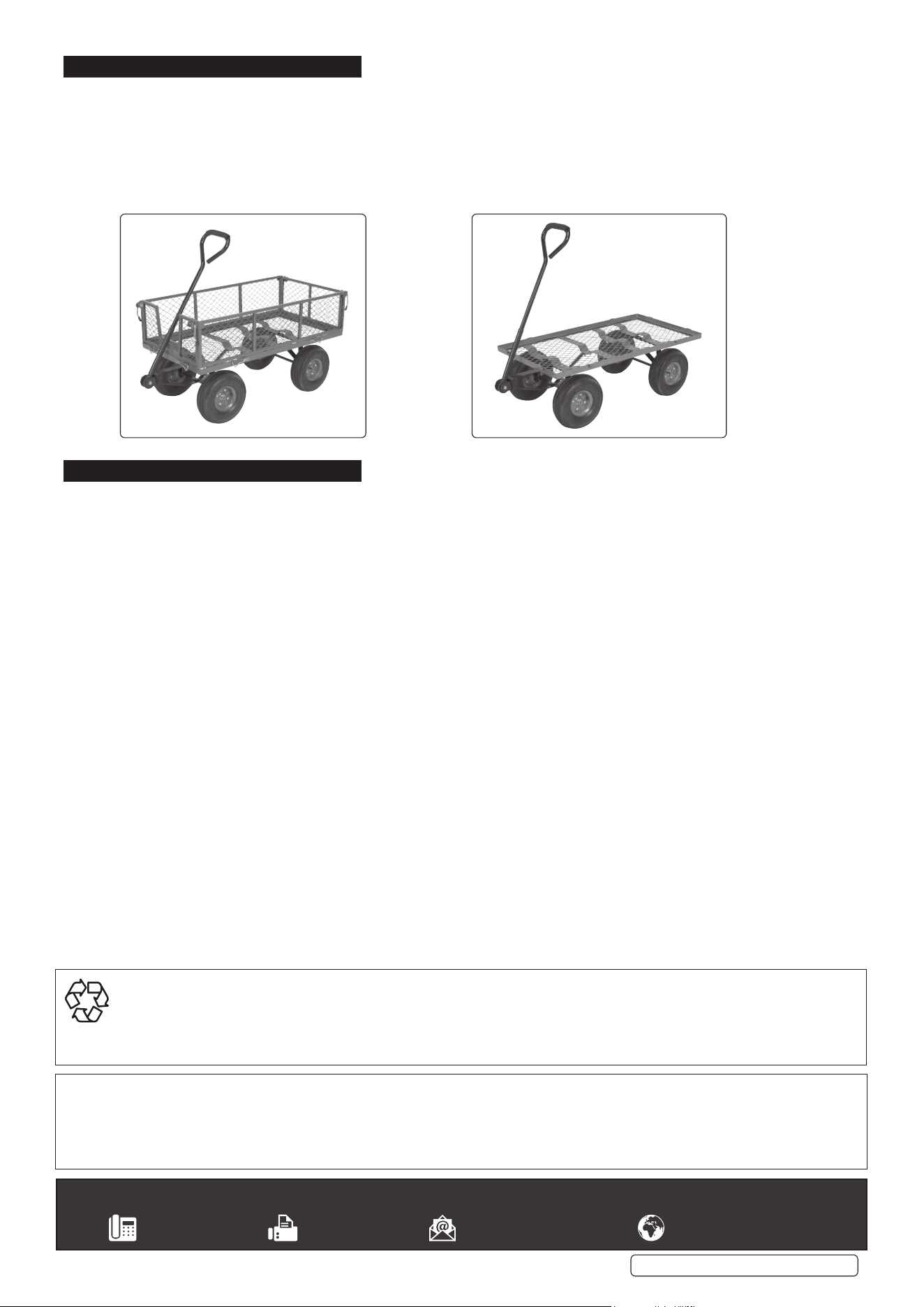
PLATFORM TRUCK WITH FOLDING/
REMOVABLE SIDES
MODEL NO: CST997.V2
Thank you for purchasing a Sealey product. Manufactured to a high standard, this product will, if used according to these
instructions, and properly maintained, give you years of trouble free performance.
I
MP
PO
R
RTA
TA
NT:
PLEA
S
E READ THE
S
E IN
S
TRU
C
TI
O
N
S
C
AREFULLY. N
O
TE THE
S
AFE
O
PERATI
O
NAL RE
Q
UIREMENT
S
, WARNIN
GS
&
C
AUTI
O
N
S
. U
S
E
TH
HE
P
PR
O
ODU
C
T
CO
RRE
C
TLY AND WITH
C
ARE F
O
R THE P
U
RP
OS
E F
O
R WHI
C
H IT I
S
INTENDED. FAIL
U
RE T
O
D
O
SO
MAY
C
A
US
E DAMA
G
E AND
/O
R
PE
ER
S
SON
N
AL IN
JU
RY AND WILL INVALIDATE THE WARRANTY. KEEP TH
ESE
IN
STR
UCT
ION
S S
AFE
FO
R F
U
T
U
RE
USE
.
1. SAFETY
Always distribute the load evenly over the surface of the bed.
Always distribute the load evenly over the surface of the bed.
DO NOT
DO NOT
overload the truck. See specifi cation.
overload the truck. See specifi cation.
DO NOT
DO NOT
leave unattended, especially when loaded, unless the wheels are chocked or the truck is otherwise secured.
leave unattended, especially when loaded, unless the wheels are chocked or the truck is otherwise secured.
DO NOT
DO NOT
use the truck on uneven ground.
use the truck on uneven ground.
DO NOT
DO NOT
run over curbs or steps. Use a ramp.
run over curbs or steps. Use a ramp.
DO NOT
DO NOT
allow others to ride on the truck.
allow others to ride on the truck.
DO NOT
DO NOT
use the truck if any part is damaged. Pay particular attention to the wheels.
use the truck if any part is damaged. Pay particular attention to the wheels.
DO NOT
DO NOT
over infl ate the tyres. See specifi cation.
over infl ate the tyres. See specifi cation.
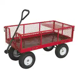
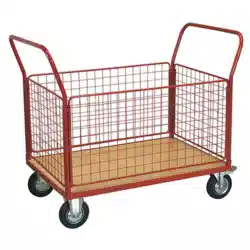
2. INTRODUCTION
Heavy-duty steel with hinged mesh construction. Cushioned grip pull handle with smooth steering action for easy manoeuvrability. Steel
centred pneumatic wheels allow transport over the toughest terrain. Drop-down sides, for easy loading, are also removable, allowing use as
a fl atbed for oversized items. Suitable for a variety of warehouse, offi ce, garden and domestic hauling applications.
3. SPECIFICATION
Model No:. ...........................................................CST997.V2
Capacity: ...................................................................... 200kg
Cart size, internal: ...................................220 x 480 x 930mm
Overall height: ............................................................ 570mm
Platform height: .......................................................... 350mm
Wheel size: ......................................................Ø259 x 90mm
4. ASSEMBLY
Unpack the product and check contents. Should there be any damaged or missing parts contact your supplier immediately.
Refer to attached parts list.
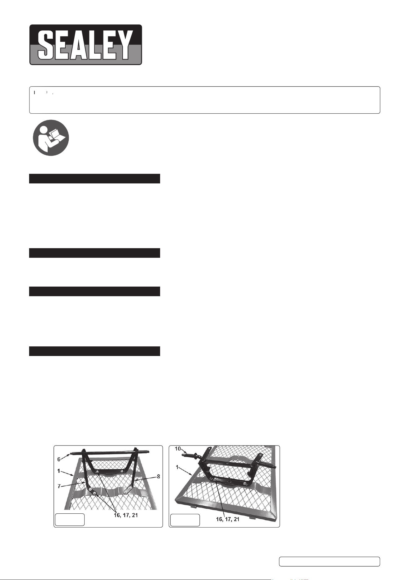
4.1. ATTACH REAR SUPPORT ASSEMBLY
4.1.1. Place the truck bed (fi g 1 - 1) upside down onto a protected fl oor (use original packaging).
4.1.2. Position rear axle support (fi g 1 - 6) onto the truck bed and secure with washer 8mm (fi g 1 - 16), nut w/lock insert 8mm (fi g 1 - 17)
and M8 x 20 carriage support bolt (fi g 1 - 21), fi nger tight only.
4.1.3. Position left rear axle support (fi g 1 - 7) and secure with washer 8mm (fi g 1 - 16), nut w/lock insert 8mm (fi g 1 - 17) and M8 x 20
carriage support bolt (fi g 1 - 21), fi nger tight only.
4.1.4. Position right rear axle support (fi g 1 - 8) and secure with washer 8mm (fi g 1 - 16), nut w/lock insert 8mm (fi g 1 - 17) and M8 x 20
carriage support bolt (fi g 1 - 21), fi nger tight only.
4.1.5. Fully tighten bolts.
4.2. ATTACH FRONT AXLE BRACE
4.2.1. Position front axle brace (fi g 2 - 10) onto the truck bed and secure with washer 8mm (fi g 2 - 16), nut w/lock insert 8mm (fi g 2 - 17)
and M8 x 20 carriage support bolt (fi g 2 - 21), fi nger tight only.
CST997.V2 Issue 3 05/10/21
Original Language Version
© Jack Sealey Limited
Refer to
instructions
fi g.1
fi g.2
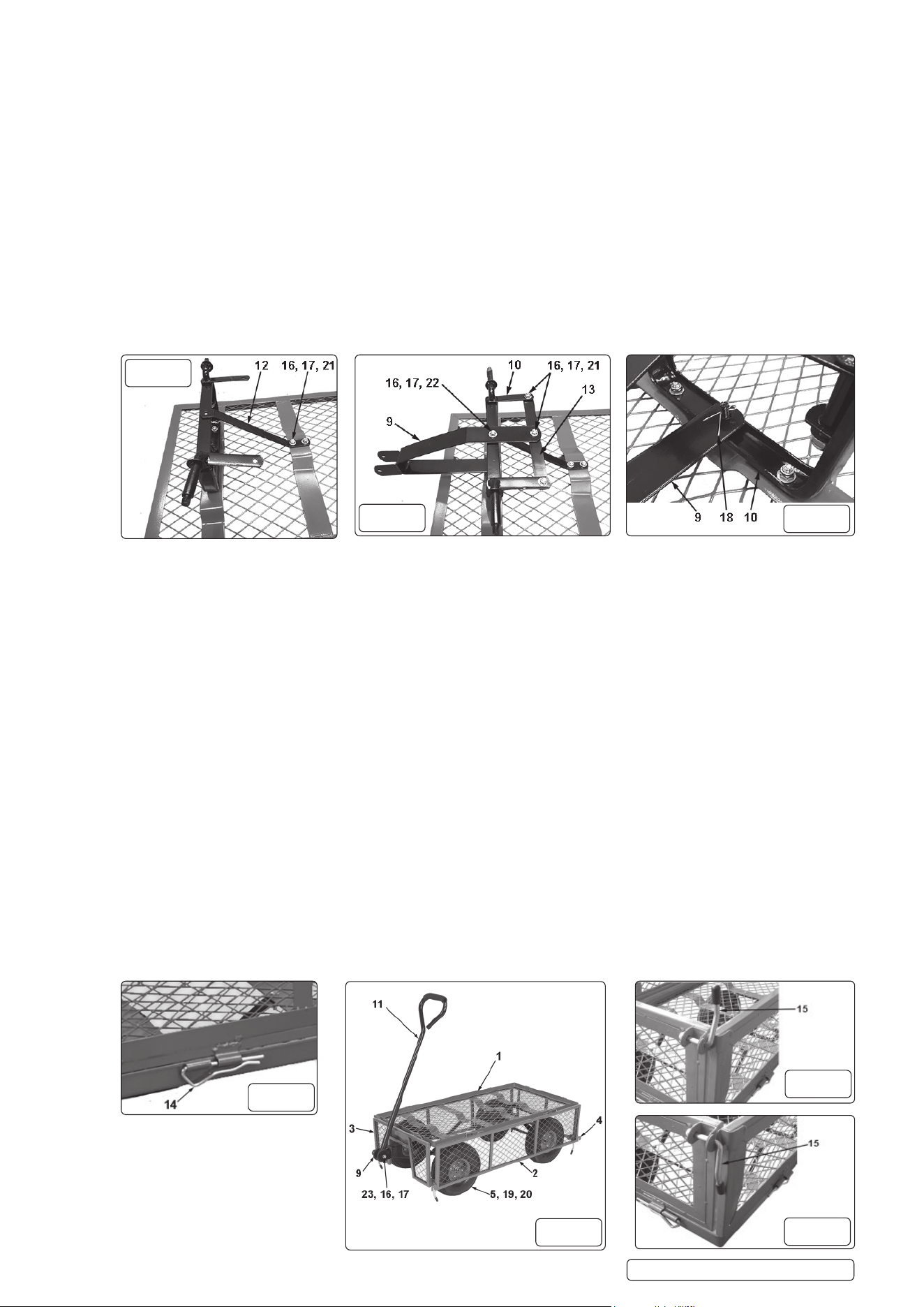
4.3. ATTACH CENTRE AXLE BRACE
4.3.1. Position centre axle brace (fi g 3 - 12) onto the truck bed and secure with washer 8mm (fi g 3 - 16), nut w/lock insert 8mm (fi g 3 - 17)
and M8 x 20 carriage support bolt (fi g 3 - 21), fi nger tight only.
4.4. ATTACH FRONT WHEEL SUPPORT BRACE
4.4.1. Locate the front wheel support brace (fi g 4 - 13) on underside of wheel axle plates on front axle brace (fi g 4 - 10) and secure with
washer 8mm (fi g 4 - 16), nut w/lock insert 8mm (fi g 4 - 17) and M8 x 20 carriage support bolt (fi g 4 - 21).
DO NOT over tighten.
4.5. ATTACH FRONT AXLE SUPPORT
4.5.1. Locate fi xing hole on lower arm of front axle support (fi g 5 - 9) onto central fi xed bolt on front axle brace (fi g 5 - 10) and secure with
pin (split) (fi g 5 - 18).
4.5.2. Secure front axle support (fi g 4 - 9) to front wheel support brace (fi g 4 - 13) with washer 8mm (fi g 4 - 16), nut w/lock insert 8mm
(fi g 4 - 17) and M8 x 20 carriage support bolt (fi g 4 - 21).
DO NOT over tighten.
4.5.3. Align the central hole on the upper arm of front axle support (fi g 4 - 9), front wheel support brace (fi g 4 - 13) and front axle brace
and secure with washer 8mm (fi g 4 - 16), nut w/lock insert 8mm (fi g 4 - 17) and M8 x 25 carriage support bolt (fi g 4 - 22).
DO NOT over tighten.
4.5.4. Fully tighten bolts attaching front axle brace (fi g 2 - 10) and centre axle brace (fi g 3 - 12) to the truck bed ONLY.
NOTE: The front wheel support assembly should be free to move.
4.6.
ATTACH THE WHEELS
4.6.1. Place a wheel (fi g 7 - 5) onto each of the axles with the valve stem facing outwards.
4.6.2. Secure with wheel nut (fi g 7 - 19) and wheel washer (fi g 7 - 20).
DO NOT over tighten. Allow the wheels to spin freely.
4.7. ATTACHING THE PULL HANDLE
4.7.1. With the assistance of another person turn the cart upright onto it’s wheels.
4.7.2. Attach the pull handle (fi g 7 - 11) and plastic coupling to the front axle support (fi g 7 - 9) securing with pull handle bolt 8 x 60mm
(fi g 7 - 23), washer 8mm (fi g 7 - 16) and nut w/lock insert 8mm (fi g 7 - 17).
4.8. ATTACHING THE SIDE FENCES
4.8.1. Position side fence (fi g 7 - 2) along side edge of bed (fi g 7 - 1) and secure with fence assembly pin (fi g 6 - 14) by inserting through
hinge tubes.
4.8.2. Repeat for other side.
NOTE: The assistance of another person may be required for this operation.
4.9. ATTACHING THE FRONT FENCE
4.9.1. Position front fence (fi g 7 - 3) along front edge of bed (fi g 7 - 1) and secure with fence assembly pin (fi g 6 - 14) by inserting through
hinge tubes.
NOTE: The lock handle 8mm (15) is supplied pre-assembled to the front fence (3).
4.10. ATTACHING THE BACK FENCE
4.10.1. Position back fence (fi g 7 - 4) along back edge of bed (fi g 7 - 1) and secure with fence assembly pin (fi g 6 - 14) by inserting through
hinge tubes.
NOTE: The lock handle 8mm (15) is supplied pre-assembled to the back fence (4).
4.11. RAISING THE SIDE AND END FENCES
4.11.1. To raise and lock side fence lift front fence (3) and move the lock handle 8mm (fi g 8 - 15) into the vertical position (fi g 8).
4.11.2. Raise the adjacent side fence so that the lock handle 8mm (fi g 8 - 15) passes through the slotted tongue on the side fence.
4.11.3. Lower the handle downwards to lock fences into position (fi g 9).
4.11.4. Repeat for all other corners.
CST997.V2 Issue 3 05/10/21
Original Language Version
© Jack Sealey Limited
fi g.4
fi g.5
fi g.3
fi g.6
fi g.7
fi g.8
fi g.9
5. TRUCK OPERATION
DO NOT overload the truck. Ensure the load is evenly distributed before use.
WARNING! On inclined surfaces and cornering, be aware of possible load shifting.
When pulling the truck proceed at a safe speed.
Chock the wheels if the truck is left loaded and unattended.
When using as a fl at bed truck remove the fence assembly pins, side and end fences and store in safe place.
DO NOT transport loads with an excessive overhang when using as a fl at bed truck.
WARNING! Truck turning circle will be restricted unless all the fence panels are removed when used as a fl at bed truck.
6. MAINTENANCE
6.1. Regularly check the condition of the tyres and keep the tyres infl ated to the specifi ed pressure.
6.2. Wash / clean the truck using a mild detergent.
CST997.V2 Issue 3 05/10/21
Original Language Version
© Jack Sealey Limited
Sealey Group, Kempson Way, Suffolk Business Park, Bury St Edmunds, Suffolk. IP32 7AR
01284 757500 01284 703534 sales@sealey.co.uk www.sealey.co.uk
ENVIRONMENT PROTECTION
Recycle unwanted materials instead of disposing of them as waste. All tools, accessories and packaging should be sorted, taken to
a recycling centre and disposed of in a manner which is compatible with the environment. When the product becomes completely
unserviceable and requires disposal, drain any fluids (if applicable) into approved containers and dispose of the product and fluids
according to local regulations.
Note: It is our policy to continually improve products and as such we reserve the right to alter data, specifications and component parts without prior
notice. Please note that other versions of this product are available. If you require documentation for alternative versions, please email or call
our technical team on technical@sealey.co.uk or 01284 757505.
Important: No Liability is accepted for incorrect use of this product.
Warranty: Guarantee is 12 months from purchase date, proof of which is required for any claim.