instructions for
platform truck 450kg capacity
model no: cSt806
thank you for purchasing a Sealey product. manufactured to a high standard, this product will, if used according to these instructions,
and properly maintained, give you years of trouble free performance.
IMPORTANT: PLEASE READ THESE INSTRUCTIONS CAREFULLY. NOTE THE SAFE OPERATIONAL REQUIREMENTS, WARNINGS & CAUTIONS. USE
THE PRODUCT CORRECTLY AND WITH CARE FOR THE PURPOSE FOR WHICH IT IS INTENDED. FAILURE TO DO SO MAY CAUSE DAMAGE AND/OR
PERSONAL INJURY AND WILL INVALIDATE THE WARRANTY. KEEP THESE INSTRUCTIONS SAFE FOR FUTURE USE.
1. SafEty
9 Always distribute the load evenly over the surface of the bed of the platform truck.
8 Do Not leave unattended, especially when loaded, unless the wheels are chocked or the truck is otherwise secured.
8 Do Not use platform truck on uneven ground and do not run over kerbs or steps - use a ramp.
8 Do Not allow others to ride on the platform truck.
8 Do Not use the truck if any part is damaged, paying particular attention to the wheels. inspect it before use each time and replace
or repair damaged or worn parts immediately.
9 check tyre pressures on the platform truck on a regular basis.
8 Do Not over inate the tyres. Recommended pressure is 25psi.
8 Do Not exceed maximum load capacity of 450kg.
8 Do Not allow children to play on, stand upon or climb on the cart.
9 Be mindful of the location of the handle it may fall from the upright position.
9 chock the wheels when loading and unloading the cart.
9 alWayS use caution when operating the platform truck. When moving it, proceed at a safe speed, especially at corners where there
could be a danger of the load shifting. extra care should be taken on inclined surfaces.
8 Do Not use the platform truck when you are tired or under the inuence of alcohol, drugs or intoxicating medication.
8 Do Not store material on the platform truck for an extended period of time.
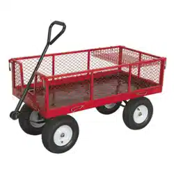
2. iNtroDuctioN
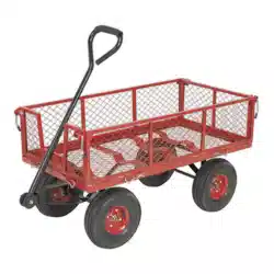
Heavy-duty rust resistant steel construction. smooth steering action for easy manoeuvrability with soft rubber gripped handle and pneumatic
wheels for easy transportation over the toughest terrain. All four sides drop down using locking pin function for easy loading. can also be used
as a at bed for transporting oversized items. Fitted with additional removable storage tray for carrying smaller items. Suitable for a variety of
warehouse, ofce, garden and domestic applications.
3. SpEcificatioN
model No: ................................................................. cSt806
maximum load capacity: ............................................... 450kg
Wheel size: ......................................................Ø300 x 90mm
internal size (length x width x depth): .... 1120 x 560 x 300mm
Platform height: .......................................................... 390mm
overall height: ............................................................ 650mm
cST806| Issue:3(L) 16/05/17
Original Language Version
© Jack sealey limited
refer to
instruction
manual
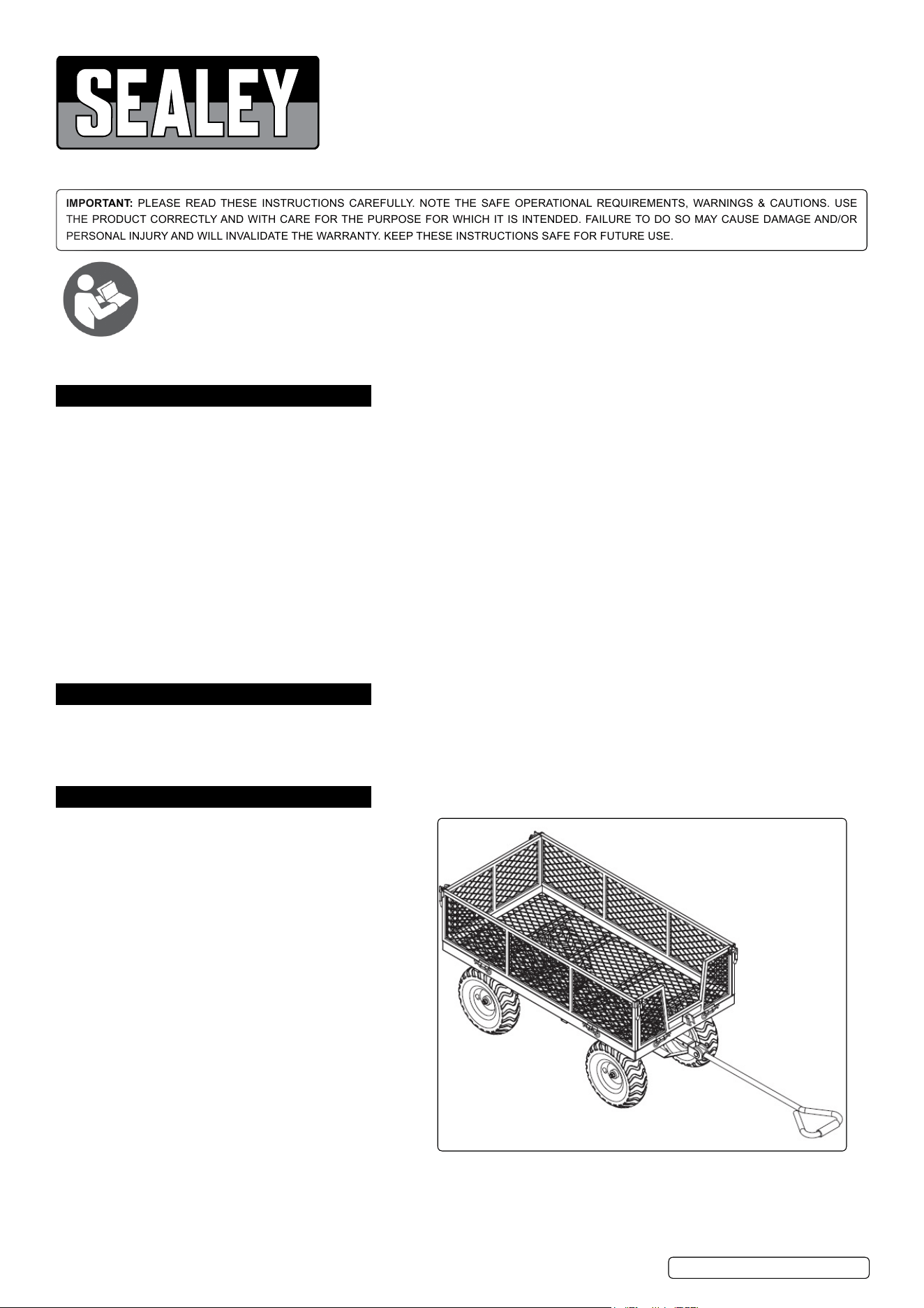
4. coNtENtS
5. aSSEmbly
5.1. Remove the contents from the packaging and check them against the contents list, g.1. Ensure that all the parts are there and not
damaged. if there are any problems contact your sealey stockist.
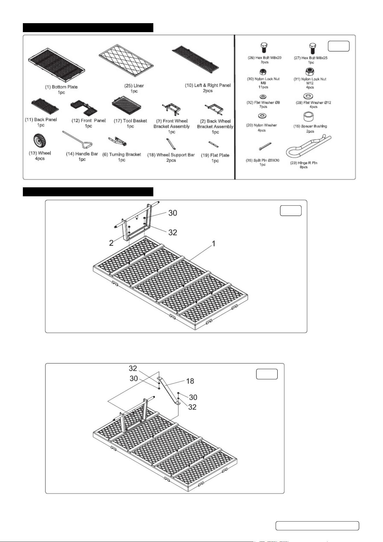
5.2. BACK WHEEL BRACKET ASSEMBLY Refer to g.2 and A and B on Parts List on back page
5.2.1. Attach the back wheel bracket assembly (2) to the bottom panel (1), using 2x8mm at washers (32) and 2xM8 lock nuts (30).
5.3. BACK WHEEL SUPPORT BAR Refer to g.3
5.3.1. Attach the wheel support bar (18), to the back wheel bracket assembly (2) and to the bottom panel (1), using 8mm at washers (32)
and M8 lock nuts (30).
g.1
g.2
g.3
cST806| Issue:3(L) 16/05/17
Original Language Version
© Jack sealey limited
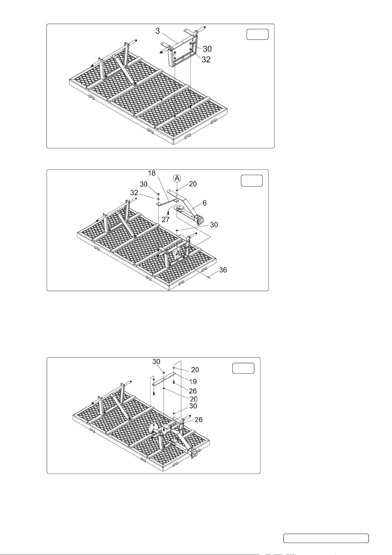
5.4. FRONT WHEEL BRACKET ASSEMBLY See g.4
5.4.1. Attach the front wheel bracket assembly (3) to the bottom panel (1), using 8mm at washers (32) and M8 lock nuts (30).
5.5. FRONT SUPPORT BAR AND TURNING BRACKET See g.5 and parts list on back page
5.5.1. Connect turning bracket (6) onto front wheel bracket (3).
5.5.2. Place turning bracket (6) over boss (see A g.5 and C on parts list on back page).
5.5.3. Secure with pin (36).
5.5.4. Connect bottom of turning bracket (6) to front wheel bracket (3) (see A on g.5 and D and E on parts list on back page), using
M8x25 bolt (27) and nylon washer (20) and M8 lock nut (30).
5.5.5. Fit wheel support bar (18) to bottom panel (1), using M8 at washer (32) and M8 lock nut (30) and turning bracket (6) (see A on
g.5).
5.6. FLAT PLATE ASSEMBLY See g.6 and F, G and H on parts list on back page
5.6.1. Place the at plate (19) between the front wheel bracket (3) and the turning bracket (6) using M8x20 bolts (26), nylon washer (20)
and M8 lock nuts (30).
g.4
g.5
g.6
cST806| Issue:3(L) 16/05/17
Original Language Version
© Jack sealey limited
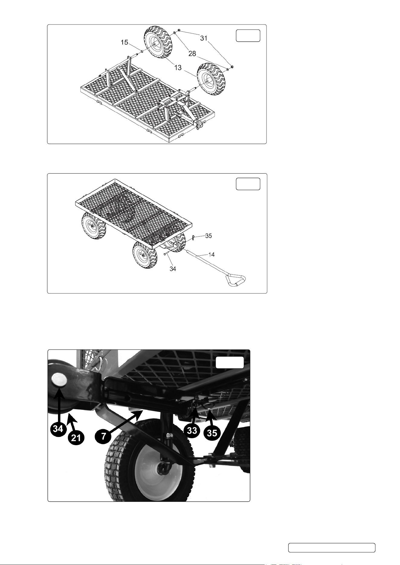
5.7. WHEEL ASSEMBLY See g.7
5.7.1. Fit spacer bush (15) onto both rear stub axles. (The front spacer bushes are tted during manufacture). Fit wheels (13) onto each
stub axle and retain with 12mm at washer (28) and M12 lock nuts (31).
5.8. HANDLE BAR ASSEMBLY/TOW BAR ASSEMBLY See g.8, g.8.1 and parts list on back page for Tow bar
5.8.1. seek assistance to turn the truck over so that it stands on its wheels.
5.8.2. Remove the R pin (35) pull out the pivot pin (34) and take out the handle connecting sleeve (21). Fit the handle bar (14) or if
desired the tow bar (7). (The tow bar is stowed within the turning axle assembly), secured with connecting plate pin (33) and R pin
(35).
Feed the handle/tow bar (14/7) through the plastic connecting sleeve, line up the holes in the sleeve and the handle (14) or tow bar
(7) with the turning axle assembly (6), insert the pivot pin (34) and secure with the R pin (35).
g.7
g.8
g.8.1
cST806| Issue:3(L) 16/05/17
Original Language Version
© Jack sealey limited
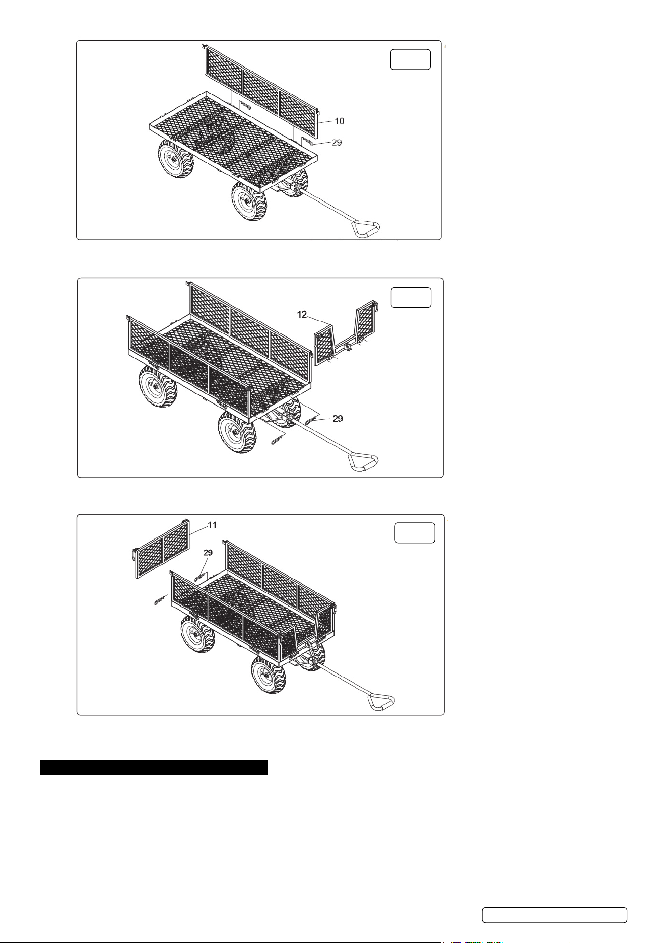
5.9. LEFT AND RIGHT SIDE PANEL ASSEMBLY See g.9
5.9.1. Connect the hinges of the left and right side panels (10) and the hinges on the bottom panel (1) using 4xR pins (29).
5.10. fRONT PANEL ASSEMBLY See g.10
5.10.1. connect the hinge of the front panel (12) and the hinge of the bottom panel (1) using 2xR pins.
5.11. bACK PANEL ASSEMBLY See g.11
5.11.1. connect the hinges of the back panel (11) and the hinges of the bottom panel (1), using 2xR pins (29).
5.11.2. Place the liner (25) on the bottom panel (1) and the tool basket (17) across the side panels.
6. maiNtENaNcE
6.1. Periodically check all fasteners for tightness.
6.2. check tyre pressures on a regular basis. Do Not over inate them - recommended pressure is 25psi.
6.3. regularly clean and lightly lubricate all moving parts.
6.4. use genuine sealey parts to replace any worn or damaged items.
6.5. Do Not store material on the platform truck for extended periods of time.
6.6. Before storing the platform truck, make sure it is clean and dry. store it in a safe, dry childproof location.
g.9
g.10
g.11
cST806| Issue:3(L) 16/05/17
Original Language Version
© Jack sealey limited
Environmental protection
recycle unwanted materials instead of disposing of them as waste. all tools, accessories and packaging should be
sorted, taken to a recycling centre and disposed of in a manner which is compatible with the environment.
When the product becomes completely unserviceable and requires disposal, drain off any fluids (if applicable)
into approved containers and dispose of the product and the fluids according to local regulations.
NOTE: It is our policy to continually improve products and as such we reserve the right to alter data, specifications and component parts without prior notice.
importaNt: no liability is accepted for incorrect use of this product.
WarraNty: Guarantee is 12 months from purchase date, proof of which will be required for any claim.
01284 757500
01284 703534
sales@sealey.co.uk
Sole uk Distributor, Sealey group,
Kempson Way, suffolk Business Park,
Bury st. edmunds, suffolk,
IP32 7AR
www.sealey.co.uk
cST806| Issue:3(L) 16/05/17
Original Language Version
© Jack sealey limited
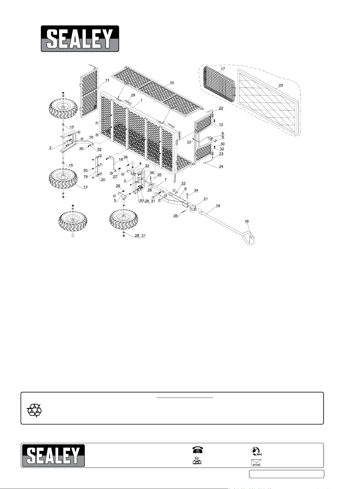
ITEM PART NO DESCRIPTION ITEM PART NO DESCRIPTION
1 CST806.01 BOTTOM PANEL 20 CST806.20N NYLON WASHER
2 CST806.02 BACK WHEEL BRACKET 21 CST806.21 HANDLE CONNECTING SLEEVE
3 CST806.03 FRONT WHEEL BRACKET 22 CST806.22 LOCK HANDLE (A)
4 CST806.04 AXLE TURNING ASS'Y (L.H) 23 CST806.23 LOCK HANDLE (B)
5 CST806.05 AXLE TURNING ASS'Y (R.H) 24 CST806.24 LOCK HANDLE SLEEVE
6 CST806.06 TURNING AXLE ASS'Y 25 CST806.25 PLATFORM
7 CST806.07 TOW BAR 26 CST806.26N HEX BOLT (M8x20)
8 CST806.08N CLAMP 27 CST806.27 HEX BOLT (M8x25)
9 CST806.09N SCREW (M5x16) 28 CST806.28 FLAT WASHER (12mm)
10 CST806.10 LEFT & RIGHT SIDE PANEL 29 CST806.29 HINGE R-PIN
11 CST806.11 BACK PANEL 30 CST806.30 LOCK NUT (M8)
12 CST806.12 FRONT PANEL 31 CST806.31 LOCK NUT (M12)
13 CST806.13 PNEUMATIC WHEEL 32 CST806.32 FLAT WASHER (8mm)
14 CST806.14 HANDLE 33 CST806.33 CONNECTING PLATE PIN
15 CST806.15N SPACER BUSHING 34 CST806.34 HANDLE PIN (8x60)
16 CST806.16 HANDLE GRIP 35 CST806.35 R-PIN
17 CST806.17 TOOL BASKET 36 CST806.36 COTTER PIN (3x30)
18 CST806.18 FRONT WHEEL BRACKET ASS'Y 37 CST806.37N LOCK NUT (M5)
19 CST806.19 FLAT PLATE
PARTS FOR
PLATFORM TRUCK with SIDES PNEUMATIC TYRES
MODEL :
CST806
Issue: 2
Issue Date: 010515