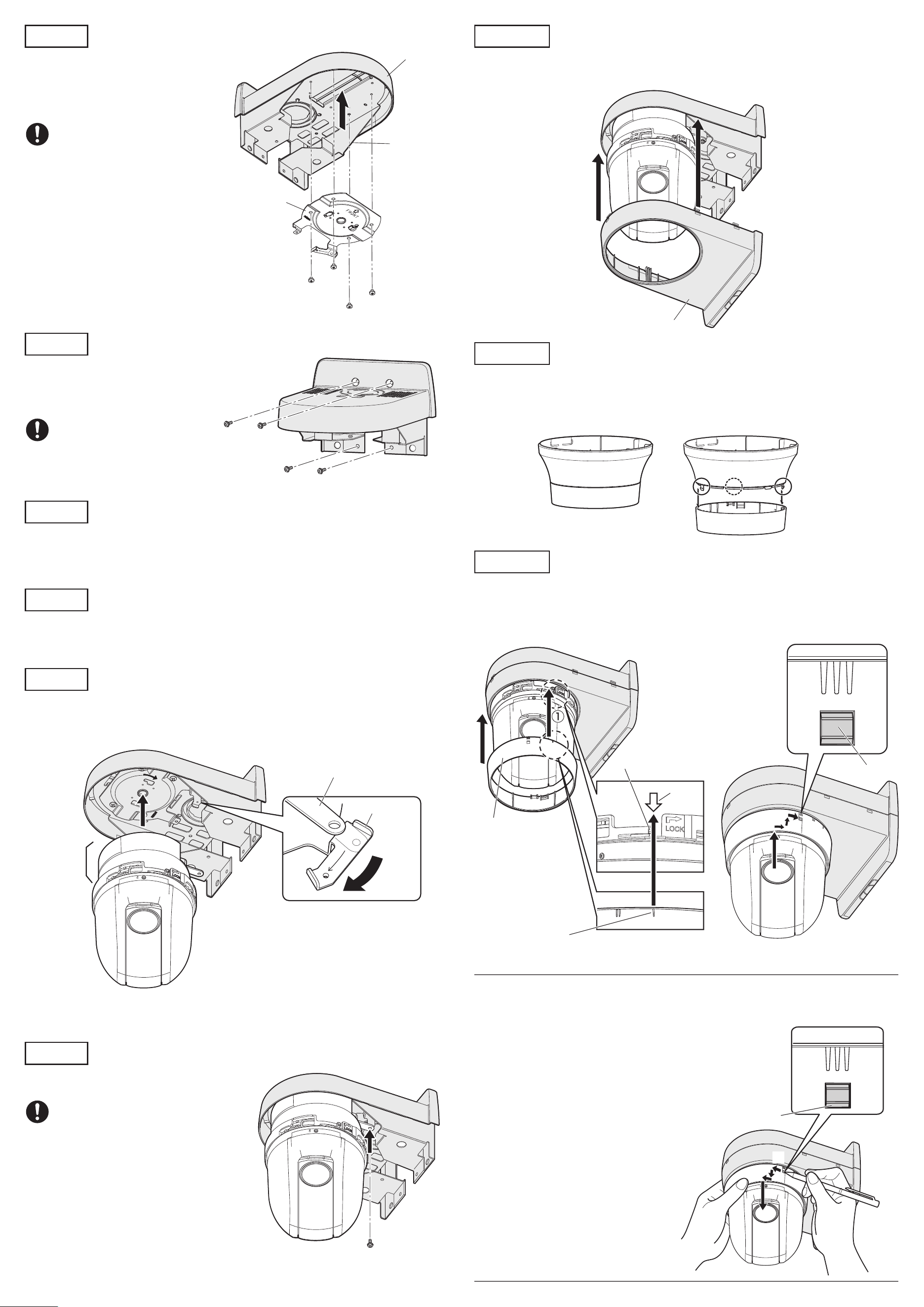
Step 4
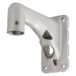
Attach the camera mount bracket to the upper case.
Mount the camera mount bracket (camera
accessory) with screws (M4 x 4 mm {5/32 inches}:
accessory) in the consideration of the bracket
direction as shown in the drawing right.
Recommended tightening torque:
1.56 N·m {1.15 lbf·ft}
Other items that are needed (not included)
Fixing screw (M4) or anchor ............................................................ 4 pcs.
IMPORTANT
• Minimum pullout strength: 196 N {44 lbf} (per 1 pc.)
• Refer to our technical information website <Control No.: C0120> for information on the mini-
mum pull-out strength.
•
Select screws according to the material of the location that the camera will be mounted to.
In this case, wood screws and nails should not be used.
Ns0522-0
Printed in China
Wall Mount Bracket
Model No. WV-QWL100
Operating Instructions
• Before attempting to connect or install this product, please read these instructions carefully and
save this manual for future use.
• The external appearance and other parts shown in this manual may differ from the actual product
within the scope that will not interfere with normal use due to improvement of the product.
Preface
This product is a wall mount bracket that is designed to mount the network camera on a wall. The
network camera will be installed after attaching this product to a junction box or concrete wall, etc.
The latest information about the supported cameras
<Control No.:C0501>
Do not use this bracket except with suitable cameras.
Failure to observe this may cause a drop resulting in injury or accidents.
Refer installation work to the dealer.
Installation work requires technique and experience. Failure to observe this may cause fire, electric
shock, injury, or damage to the product.
Be sure to consult the dealer.
The screws and bolts must be tightened to the specied torque.
Failure to observe this may cause a drop resulting in injury or accidents.
Install the product securely on a wall in accordance with the installation instructions.
Failure to observe this may cause injury or accidents.
Do not rub the edges of metal parts with your hand.
Failure to observe this may cause injury.
When using this product, also read the “Precautions” described in the operating
instructions for the camera to be attached.
Precautions
Installation
i-PRO Co., Ltd. assumes no responsibility for injuries or property damage resulting
from failures arising out of improper installation or operation inconsistent with this
documentation.
Caution:
• Before attempting to connect or operate this
product, please read these instructions care-
fully.
Notice:
• This product is not suitable for use in loca-
tions where children are likely to be present.
• Do not install this product in locations where
ordinary persons can easily reach.
• For information about screws and other parts
required for installation, refer to the corre-
sponding section of this document.
Included Installation Instructions
Specifications
In order to prevent injury, the product must be securely mounted to the wall according
to the Installation Guide of this product.
This product is designed to be used indoors.
This product is not operable outdoors. Do not expose this product to direct sunlight for hours and
do not install the product near a heater or an air conditioner. Otherwise, it may cause deformation,
discoloration and malfunction. Keep this product away from water and moisture.
Installation area for this product
• Make sure that the installation area is strong enough to hold the total weight of the camera
assembly before installation.
• Do not mount the product on a plaster board or a wooden section because they are too weak. If
the product is unavoidably mounted on such a section, the section shall be sufficiently reinforced.
Make sure to remove this product if it will no longer be used.
Precautions for installation
Standard Accessories
Screws ..........................................................5 pcs. (of them, 1 for spare)
(M4 x 4 mm {5/32 inches}, for securing camera mount bracket)
Template ...........................................................................................1 pc.
Operating Instructions (this document) ..............................................1 pc.
Refer to the operating instructions of the camera for details on the camera installation
(including the camera mounting, cable connection and adjustment).
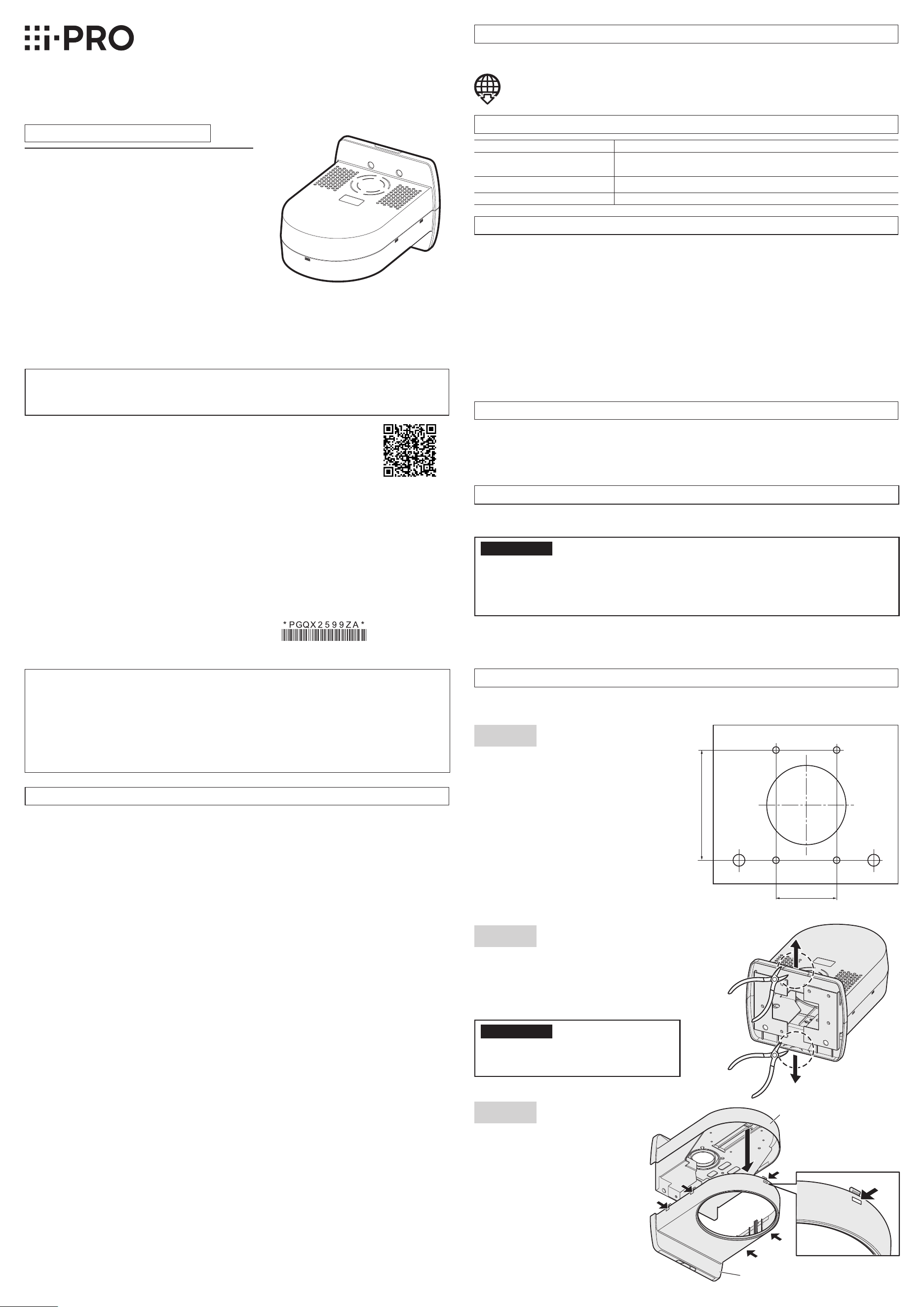
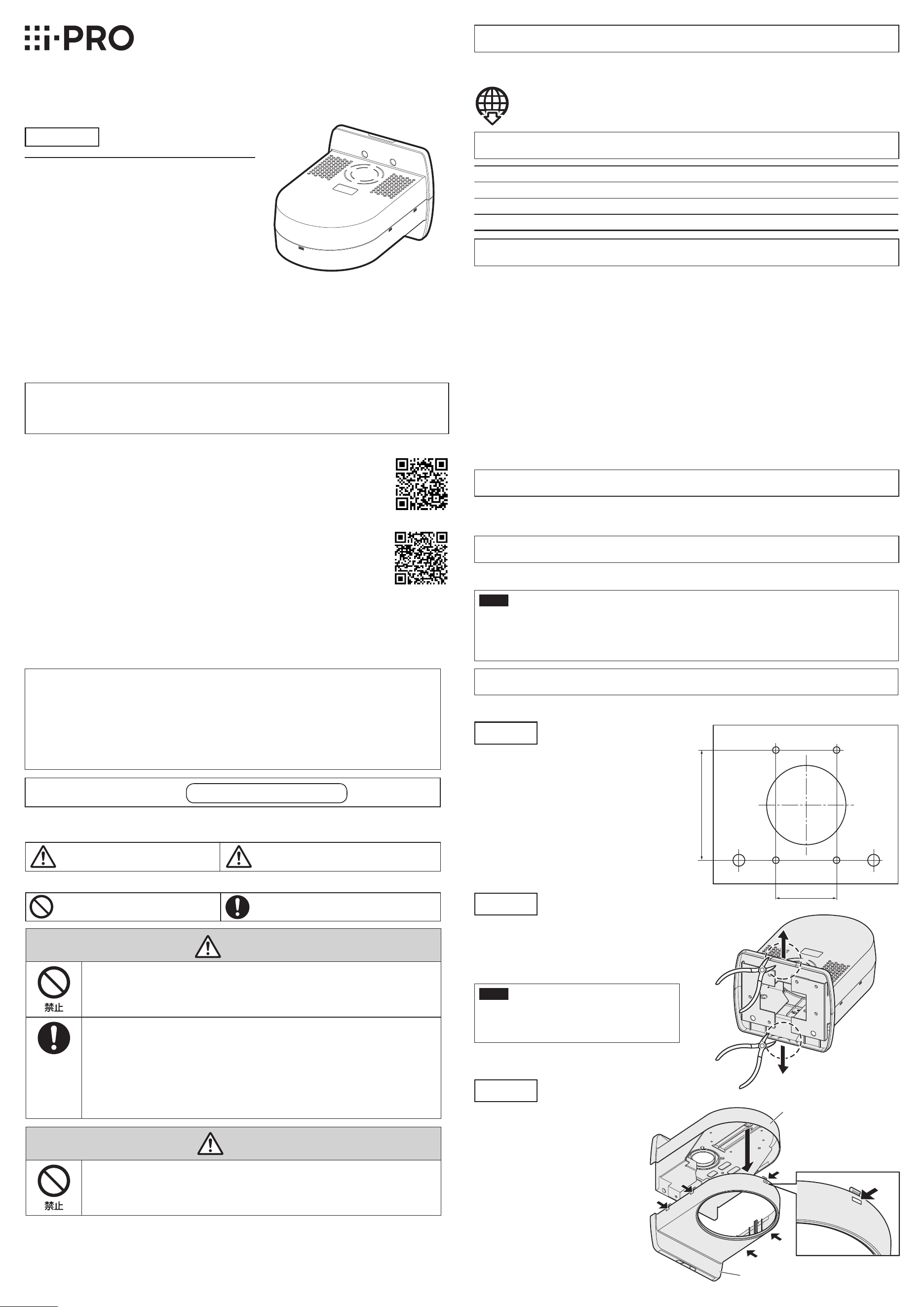
Step 1
Put the template (accessory) against the wall
and mark the positions of fixing screws (M4,
locally procured) and the hole through which
the cables are laid.
If cables are routed inside the wall, bore a
hole through the wall.
Drill 4 holes on the wall to secure it with M4
screws. The hole diameter shall be decided
in accordance with the specifications of the
screws and anchors to be used. When the
cables are laid inside the wall, drill a hole
through the wall for cable installation.
Step 2
When connection is performed without drilling
the wall for cable installation, cut off the notch
marked with a circle drawn with a dotted line on
the upper or lower case with a nipper for cable
installation.
IMPORTANT
• To prevent injuries and protect the cables,
finish the side cable access hole with a file
to avoid sharp edges.
Step 3
Remove the lower case of the main unit.
The case can be removed by pulling
down it while pressing the ribs
(5 places) marked with arrows.
Ambient operating temperature: –10 °C to +55 °C {14 °F to 131 °F}
Dimensions: 165 mm (W) x 140 mm (H) x 217.5 mm (D)
{6-1/2 inches (W) x 5-1/2 inches (H) x 8-9/16 inches (D)}
Mass:
Approx. 650 g {1.43 lbs}
Finish: ABS resin, i-PRO white
Step 5
Attach the upper case and the chassis to the wall
and run the cables.
Attach it with four screws. Screws are not provided.
Prepare them in accordance with the camera
installation position.
Necessary screw: M4 (4 pcs.)
Minimum pull-out strength: 196 N
{44 lbf} (per 1 pc.)
Step 10
Engage the 5 hooks to mount the lower case.
Ensure the lower case and the camera mount bracket are steadily fit with each other.
“<Control No.: C****>” used in these documents should be used to search for
information on our technical information website (https://i-pro.com/global/en/
surveillance/training-support/support/technical-information) and will guide you to
the right information.
© i-PRO Co., Ltd. 2022
i-PRO Co., Ltd.
https://www.i-pro.com/
83.5 mm
{3-9/32 inches}
46 mm
{1-13/16 inches}
Upper case
Lower case
Screw
(M4 x 4 mm {5/32 inches}: accessory)
Upper case
Camera mount bracket
(camera accessory)
Chassis
Screws
(M4, locally procured)
Step 6
Connect the cables to the external I/O terminals, audio input connector, or audio output connector.
Refer to the operating instructions of the camera for descriptions of connections. Hold the camera
main body fixing part securely at connections.
Step 7
Connect the cables to the RJ45 network terminal and power supply terminal (12 V DC).
Refer to the operating instructions of the camera for descriptions of connections.
* Be sure to mount it with holding the camera main body fixing part.
Camera fixing screw
(M3, camera accessory)
Lower case
Decorative cover
(lower)
“l” mark
Arrow
Lock lever
③Ensure that the lock lever is securely inserted into the hole of the decorative cover (lower).
Note:
• WV-QDC100 (dome cover) can be also directly installed with this product. In such a case, the
decorative cover (both upper and lower) supplied with the camera is not used.
• Follow the instructions as below to remove the
decorative cover (lower).
①Rotate the lock lever by approx. 16 degrees
counterclockwise when viewing the decorative
cover (lower) from underneath (in the direction
of ← in the drawing) while pressing the lock
lever, and pull it slightly downward.
②Rotate the decorative cover (lower) more
approx. 16 degrees counterclockwise (in the
direction of ← in the drawing), and pull it out
downward.
②
③
Lock lever
①Align the “l” mark of the decorative cover
(lower) with the arrow located above the lock
lever of the camera body and insert it from
underneath by holding the decorative cover
(lower).
②Rotate the decorative cover (lower) clockwise
when looking at it from underneath by approx.
16 degrees to insert it upward.
Rotate the decorative cover clockwise by 16
degrees more to secure it.
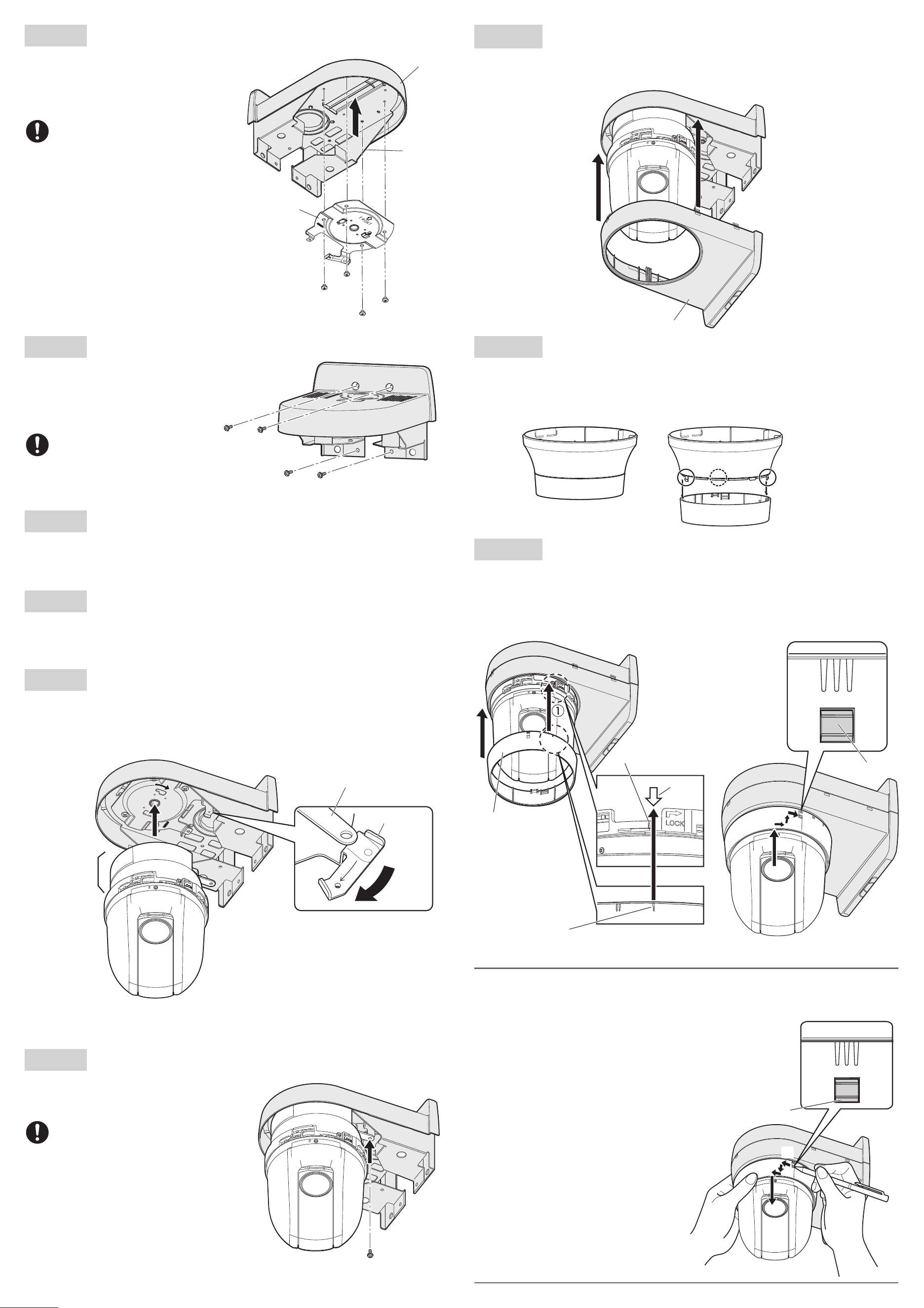
Step 8
Mount the camera onto the camera mount bracket.
Align the lock plate with the guide of the camera mount bracket, engage the bracket with the cam-
era body while aligning the center of the bracket with the center of the camera, and rotate the cam-
era body clockwise while pressing the camera to the camera mount bracket.
Step 9
Secure the camera mount bracket to the camera
with 1 piece of the camera fixing screw
(M3, camera accessory).
Recommended tightening torque:
0.68 N·m {0.5 lbf·ft}
Lock plate
Guide
Approx. 20°
Camera main
body fixing part
Step 11
Remove the decorative cover (lower) from the decorative cover supplied with the camera.
The decorative cover is secured with 3 hooks.
* The decorative cover (upper) is not used for mounting this product.
Step 12
Decorative cover
Decorative cover (lower)
Decorative cover (upper)
①
②
Lock lever
Step 4
Attach the camera mount bracket to the upper case.
Mount the camera mount bracket (camera
accessory) with screws (M4 x 4 mm {5/32 inches}:
accessory) in the consideration of the bracket
direction as shown in the drawing right.
Recommended tightening torque:
1.56 N·m {1.15 lbf·ft}
Other items that are needed (not included)
Fixing screw (M4) or anchor ............................................................ 4 pcs.
IMPORTANT
• Minimum pullout strength: 196 N {44 lbf} (per 1 pc.)
• Refer to our technical information website <Control No.: C0120> for information on the mini-
mum pull-out strength.
•
Select screws according to the material of the location that the camera will be mounted to.
In this case, wood screws and nails should not be used.
Ns0522-0
Printed in China
Wall Mount Bracket
Model No. WV-QWL100
Operating Instructions
• Before attempting to connect or install this product, please read these instructions carefully and
save this manual for future use.
• The external appearance and other parts shown in this manual may differ from the actual product
within the scope that will not interfere with normal use due to improvement of the product.
Preface
This product is a wall mount bracket that is designed to mount the network camera on a wall. The
network camera will be installed after attaching this product to a junction box or concrete wall, etc.
The latest information about the supported cameras
<Control No.:C0501>
Do not use this bracket except with suitable cameras.
Failure to observe this may cause a drop resulting in injury or accidents.
Refer installation work to the dealer.
Installation work requires technique and experience. Failure to observe this may cause fire, electric
shock, injury, or damage to the product.
Be sure to consult the dealer.
The screws and bolts must be tightened to the specied torque.
Failure to observe this may cause a drop resulting in injury or accidents.
Install the product securely on a wall in accordance with the installation instructions.
Failure to observe this may cause injury or accidents.
Do not rub the edges of metal parts with your hand.
Failure to observe this may cause injury.
When using this product, also read the “Precautions” described in the operating
instructions for the camera to be attached.
Precautions
Installation
i-PRO Co., Ltd. assumes no responsibility for injuries or property damage resulting
from failures arising out of improper installation or operation inconsistent with this
documentation.
Caution:
• Before attempting to connect or operate this
product, please read these instructions care-
fully.
Notice:
• This product is not suitable for use in loca-
tions where children are likely to be present.
• Do not install this product in locations where
ordinary persons can easily reach.
• For information about screws and other parts
required for installation, refer to the corre-
sponding section of this document.
Included Installation Instructions
Specifications
In order to prevent injury, the product must be securely mounted to the wall according
to the Installation Guide of this product.
This product is designed to be used indoors.
This product is not operable outdoors. Do not expose this product to direct sunlight for hours and
do not install the product near a heater or an air conditioner. Otherwise, it may cause deformation,
discoloration and malfunction. Keep this product away from water and moisture.
Installation area for this product
• Make sure that the installation area is strong enough to hold the total weight of the camera
assembly before installation.
• Do not mount the product on a plaster board or a wooden section because they are too weak. If
the product is unavoidably mounted on such a section, the section shall be sufficiently reinforced.
Make sure to remove this product if it will no longer be used.
Precautions for installation
Standard Accessories
Screws ..........................................................5 pcs. (of them, 1 for spare)
(M4 x 4 mm {5/32 inches}, for securing camera mount bracket)
Template ...........................................................................................1 pc.
Operating Instructions (this document) ..............................................1 pc.
Refer to the operating instructions of the camera for details on the camera installation
(including the camera mounting, cable connection and adjustment).
Step 1
Put the template (accessory) against the wall
and mark the positions of fixing screws (M4,
locally procured) and the hole through which
the cables are laid.
If cables are routed inside the wall, bore a
hole through the wall.
Drill 4 holes on the wall to secure it with M4
screws. The hole diameter shall be decided
in accordance with the specifications of the
screws and anchors to be used. When the
cables are laid inside the wall, drill a hole
through the wall for cable installation.
Step 2
When connection is performed without drilling
the wall for cable installation, cut off the notch
marked with a circle drawn with a dotted line on
the upper or lower case with a nipper for cable
installation.
IMPORTANT
• To prevent injuries and protect the cables,
finish the side cable access hole with a file
to avoid sharp edges.
Step 3
Remove the lower case of the main unit.
The case can be removed by pulling
down it while pressing the ribs
(5 places) marked with arrows.
Ambient operating temperature: –10 °C to +55 °C {14 °F to 131 °F}
Dimensions: 165 mm (W) x 140 mm (H) x 217.5 mm (D)
{6-1/2 inches (W) x 5-1/2 inches (H) x 8-9/16 inches (D)}
Mass:
Approx. 650 g {1.43 lbs}
Finish: ABS resin, i-PRO white
Step 5
Attach the upper case and the chassis to the wall
and run the cables.
Attach it with four screws. Screws are not provided.
Prepare them in accordance with the camera
installation position.
Necessary screw: M4 (4 pcs.)
Minimum pull-out strength: 196 N
{44 lbf} (per 1 pc.)
Step 10
Engage the 5 hooks to mount the lower case.
Ensure the lower case and the camera mount bracket are steadily fit with each other.
“<Control No.: C****>” used in these documents should be used to search for
information on our technical information website (https://i-pro.com/global/en/
surveillance/training-support/support/technical-information) and will guide you to
the right information.
© i-PRO Co., Ltd. 2022
i-PRO Co., Ltd.
https://www.i-pro.com/
83.5 mm
{3-9/32 inches}
46 mm
{1-13/16 inches}
Upper case
Lower case
Screw
(M4 x 4 mm {5/32 inches}: accessory)
Upper case
Camera mount bracket
(camera accessory)
Chassis
Screws
(M4, locally procured)
Step 6
Connect the cables to the external I/O terminals, audio input connector, or audio output connector.
Refer to the operating instructions of the camera for descriptions of connections. Hold the camera
main body fixing part securely at connections.
Step 7
Connect the cables to the RJ45 network terminal and power supply terminal (12 V DC).
Refer to the operating instructions of the camera for descriptions of connections.
* Be sure to mount it with holding the camera main body fixing part.
Camera fixing screw
(M3, camera accessory)
Lower case
Decorative cover
(lower)
“l” mark
Arrow
Lock lever
③Ensure that the lock lever is securely inserted into the hole of the decorative cover (lower).
Note:
• WV-QDC100 (dome cover) can be also directly installed with this product. In such a case, the
decorative cover (both upper and lower) supplied with the camera is not used.
• Follow the instructions as below to remove the
decorative cover (lower).
①Rotate the lock lever by approx. 16 degrees
counterclockwise when viewing the decorative
cover (lower) from underneath (in the direction
of ← in the drawing) while pressing the lock
lever, and pull it slightly downward.
②Rotate the decorative cover (lower) more
approx. 16 degrees counterclockwise (in the
direction of ← in the drawing), and pull it out
downward.
②
③
Lock lever
①Align the “l” mark of the decorative cover
(lower) with the arrow located above the lock
lever of the camera body and insert it from
underneath by holding the decorative cover
(lower).
②Rotate the decorative cover (lower) clockwise
when looking at it from underneath by approx.
16 degrees to insert it upward.
Rotate the decorative cover clockwise by 16
degrees more to secure it.
Step 8
Mount the camera onto the camera mount bracket.
Align the lock plate with the guide of the camera mount bracket, engage the bracket with the cam-
era body while aligning the center of the bracket with the center of the camera, and rotate the cam-
era body clockwise while pressing the camera to the camera mount bracket.
Step 9
Secure the camera mount bracket to the camera
with 1 piece of the camera fixing screw
(M3, camera accessory).
Recommended tightening torque:
0.68 N·m {0.5 lbf·ft}
Lock plate
Guide
Approx. 20°
Camera main
body fixing part
Step 11
Remove the decorative cover (lower) from the decorative cover supplied with the camera.
The decorative cover is secured with 3 hooks.
* The decorative cover (upper) is not used for mounting this product.
Step 12
Decorative cover
Decorative cover (lower)
Decorative cover (upper)
①
②
Lock lever
Step2
壁面に配線用穴をあけずに接続する場合は、
配線処理用に上もしくは下ケース点線円内の
切り欠き部分をニッパーなどで切り離して
ください。
重要
けが防止およびケーブル保護のため、
側面ケーブル通し穴はエッジにならない
ようにヤスリなどで仕 上げてください 。
Step11
カメラに同梱されている飾りカバーから、飾りカバー(下)を取り外します。飾りカバーは爪3か所
で固定されています。
※飾りカバー(上)の部分は本機の設置では使用しません。
Step12
Step9
カメラ固定ねじ(M3、カメラ付属品)1本でカメラと
カメラ取付金具を固定します。
推奨締付トルク:
0.68N・m{7kgf・cm}
Step10
爪5か所をはめ合わせて下ケースを取り付けます。
確実にはまっていることを確認してください。
Step6
外部I/O端子、オーディオ入力端子、オーディオ出力端子にケーブルを接続します。
接続のしかたはカメラの取扱説明書をお読みください。接続する際はカメラ本体固定部をしっか
りと持って行ってください。
Step7
RJ45ネットワーク端子、電源接続端子(DC12V)にケーブルを接続します。
接続のしかたはカメラの取扱説明書をお読みください。
Step8
カメラ取付金具にカメラを取り付けます。
カメラ取付金具のガイドにロックプレートを合わせ、金具の中心部とカメラの中心部を合わせて
本金具に差し込み、カメラ取付金具にカメラ本体を押しつけながら、時計回りに回します。
Step4
上ケースにカメラ付属のカメラ取付金具
を取り付けます。
ねじ(M4×4mm:付属品)を使用し、
カメラ取付金具(カメラ付属品)を右図
の向きで取り付けてください。
推奨締付トルク:
1.56N・m{16kgf・cm}
Step5
上ケースとシャーシを壁に取り付け、ケーブル類を
配線します。
ねじで4か所を固定します。ねじは付属していません。
取り付け場所に合わせて用意してください。
必要なねじ:M4(4本)
最低引抜強度:
196N{20kgf}/1本あたり
Step3
本金具の下ケースを外します。
下ケースの矢印に示すリブ(5か所)
を押しながら下げると外れます。
警告
■■ 専用のカメラ以外は取り付けない
(落下によるけがや事故の原因となります。)
■■ 工事は販売店に依頼する
(工事には技術と経験が必要です。火災、感電、けが、器物損壊の原因となります。)
⇒必ず販売店に依頼してください。
■■ ねじやボルトは指定されたトルクで締め付ける
(落下によるけがや事故の原因となります。)
■■ 設置の説明にしたがって壁面にしっかり取り付ける
(けがや事故の原因となります。)
注意
■■ 金属のエッジで手をこすらない
(強くこするとけがの原因となります。)
本金具をご使用の際は、取り付けるカメラの取扱説明書に記載された「安全上のご
注意」とあわせてお読みください。
安全上のご注意
必ずお守りください
■■ お守りいただく内容を次の図記号で説明しています。(次は図記号の例です)
人への危害、財産の損害を防止するため、必ずお守りいただくことを説明しています。
■■ 誤った使い方をしたときに生じる危害や損害の程度を区分して、説明しています。
「死亡や重傷を負うおそ
れがある内容」です。
「軽傷を負うことや、財産の損害が
発生するおそれがある内容」で
す。
警告
注意
してはいけない内容で
す。
実行しなければならない内容
です。
注意:
取扱説明書をよくお読みのうえ、正しく
安全にお使いください。
注記:
本金具は子供がいる可能性のある場所で
の使用には適していません。
一般の人が容易に触れることができる場
所への設置はしないでください。
設置に必要なねじやそのほかの部材などの情報
については本書の該当部分を参照してください。
取扱説明書
工事説明付き
カメラ壁取付金具
品番
WV-QWL100
このたびは、弊社製品をお買い上げいただき、まことにありがとうございます。
取扱説明書をよくお読みのうえ、正しく安全にお使いください。
ご使用前に「安全上のご注意」を必ずお読みください。
この取扱説明書は大切に保存してください。
製品の改良などにより、ご使用上影響のない範囲で、記載されている外観などが実際の製
品と異なる場合があります。
取扱説明書に記載されていない方法や、指定の部品を使用しない方法で施工されたことによ
り事故や損害が生じたときには、当社では責任を負えません。また、その施工が原因で故障
が生じた場合は、製品保証の対象外となります。
i-PRO製品の「お問い合わせ」については、以下の弊社サポートウェブサイト
を参照してください。
https://i-pro.com/jp/ja/support_portal
※「日本エリア」でお使いの場合に限ります。日本以外でお使いの場合のサービスは
いたしかねます。
取扱説明書に記載されている「<管理番号:Cxxxx>」は、以下の弊社技術情
報ウェブサイト内で該当する情報を検索する際に使用する番号です。
https://i-pro.com/jp/ja/support_portal/technical_information
i-PRO株式会社
i-PRO Co., Ltd. 2022
https://www.i-pro.com/
商品概要
本金具は、カメラ用の壁取付金具です。スイッチボックス、コンクリート壁などに本金具を取り
付け、カメラを設置します。
取り付け可能なカメラの最新情報
<管理番号:C0501 >
仕様
使用温度範囲 −10℃〜+ 55℃
寸法 幅:165mm /高さ:140mm /奥行:217.5mm
質量 約650g
仕上げ ABS樹脂 i-PROホワイト
設置上のお願い
■■ 設置工事は電気設備技術基準に従って実施してください。
本金具の設置・接続を始める前に必要な周辺機器やケーブルを確認し、準備してください。接続
する前に、カメラ、PCなど接続する機器の電源を切ってください。
■■ 傷害防止のため、本金具は、設置の説明に従って壁面にしっかりと取り付ける必要があります。
■■ 本機は屋内専用です
屋外での使用はできません。長時間直射日光の当たるところや、冷・暖房機の近くには設置しな
いでください。変形・変色または故障・誤動作の原因となります。また、水滴や水沫のかからな
い状態で使用してください。
■■ 本金具の取付場所について
設置場所は、カメラ取り付け時の総質量に十分耐えられる強度を持っていることを確認して
から取り付けてください。
石こうボードや木部は強度が弱いので取り付けないでください。やむを得ず取り付ける場合
は、十分な補強を施してください
■■ 本金具を使用しなくなった場合は放置せず、必ず撤去してください。
付属品をご確認ください
重要
最低引抜強度・・・196N{20kgf}/1本あたり
最低引抜強度の考え方については弊社技術情報ウェブサイト<管理番号:C0120>を参照
してください 。
ねじの種類は取付場所の材質に合わせて選択してください。木ねじおよびくぎは使用しないでください。
付属品以外に必要なもの
取付ねじ(M4)またはアンカー................4本
ねじ(M4×4mm:カメラ取付金具固定用)... 5本
(うち1本は予備)
型紙................................................................ 1枚
取扱説明書(本書)....................................... 1冊
Step1
型紙(付属品)を壁面に当て、取付ねじ(M4:
現地調達)とケーブル類を通す穴の位置を
マーキングします。
取付ねじで固定するために、壁面に4か所穴
をあけてください。穴径はご使用になるね
じ、アンカーの仕様に従って決めてください。
ケーブル類を壁面内に配線する場合は、
壁面にケーブル用の穴をあけてください。
設置する
カメラの取り付け、ケーブルの接続、調整などの詳細はカメラの取扱説明書を参照してください。
上ケース
下ケース
上ケース
カメラ取付金具
(カメラ付属品)
シャーシ
ねじ
(M4×4mm:付属品)
ねじ(M4:現地調達)
ロックプレート
ガイド
約20°
カメラ本体
固定部
83.5mm
46mm
※必ずカメラ本体固定部を持って取り付けてください。
カメラ固定ねじ
(M3:カメラ付属品)
下ケース
飾りカバー(下)
「|」マーク
矢印
ロックレバー
②
③
ロックレバー
①飾りカバー(下)を持って飾りカバー(下)
の「|」マークをカメラ本体のロックレバー
の上方にある矢印と合わせ、下側から差し
入れます。
②飾りカバー(下)を下から見て時計方向に
約16°回転させ上に差し入れます。飾り
カバーをさらに16°回転させ固定します。
③飾りカバー(下)の穴に、ロックレバーが確実に挿入されていることを確認してください。
メモ
本金具には、WV-QDC100(ドームカバー)を組み合わせて設置することもできます。
そのときには、カメラに同梱されている飾りカバー(上下両方)は使用しません。
飾りカバー(下)は以下のようにして外して
ください。
①ロックレバーを押しながら、飾りカバー(下)
を下から見て反時計回りに約16°回転させ
(図の←の方向)、下のほうに少し引きます。
②飾りカバー(下)を反時計回りにさらに約
16°回転させ(図の←の方向)、そのまま
下方に引き抜きます。
飾りカバー
飾りカバー(下)
飾りカバー(上)
①
②
ロックレバー