Step 4
Mount another cable cap (accessory) on the
cable access hole (rear) on the plate on the rear
side of the bracket.
Step 5
Mount this product on the wall with fixing screws
(4pcs.) (M10: locally procured).
Minimum pull-out strength: 823 N {185 lbf}/
per 1pc.
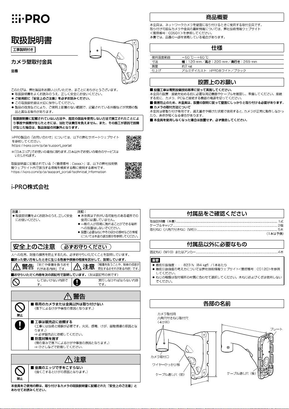
Preface
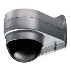
This product is used for installing the network camera on a wall. For the latest
information about the supported cameras and brackets, refer to our technical
information website
(https://i-pro.com/global/en/surveillance/training-support/support/technical-information
<Control No.: C0501>).
The model number is abbreviated in some descriptions in this manual.
Specifications
Ambient operating temperature: –50 °C to +60 °C {–58 °F to 140 °F}
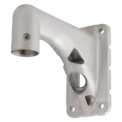
Dimensions:
120 mm (W) x 220 mm (H) x 269 mm (D)
{4-23/32 inches (W) x 8-21/32 inches (H) x 10-19/32 inches (D)}
Mass: Approx. 2 k
g
{4.42 lbs}
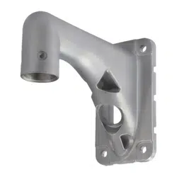
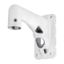
Finish: Aluminum die cast i-PRO white/ Black
Precautions for installation
In order to prevent injury, the product must be securely mounted to the wall according to
the installation guide of this bracket.
Mounting method for this product
This product is designed to be mounted on a wall. If it is mounted on a desktop or at a slant, the
camera may not work correctly and its lifetime may be shortened.
Make sure to remove this product if it will no longer be used.
Precaution
Do not use this product except with suitable cameras or brackets.
Failure to observe this may cause a drop resulting in injury.
Refer installation work to the dealer.
Installation work requires technique and experiences.
Failure to observe this may cause fire, electric shock, injury, or damage to the product.
Be sure to consult the dealer.
The measures of protection against snowfall shall be taken.
Weight of snow may cause a fall of the product resulting in injury or accidents.
Protect the product against snowfall by installing it under eaves.
Do not rub the edges of metal parts with your hand.
Strong rubbing may cause injury.
When using this product, also read the “Precautions” described in the operating instruc-
tions for the camera to be attached.
Operating Instructions
Included Installation Instructions
Wall Mount Bracket
Model No.
WV-QWL501
•
Before attempting to connect or install this product, please read these instructions carefully and
save this manual for future use.
• The external appearance and other parts shown in this manual may differ from the actual
product within the scope that will not interfere with normal use due to improvement of the
product.
i-PRO Co., Ltd. assumes no responsibility for injuries or property damage resulting
from failures arising out of improper installation or operation inconsistent with this
documentation.
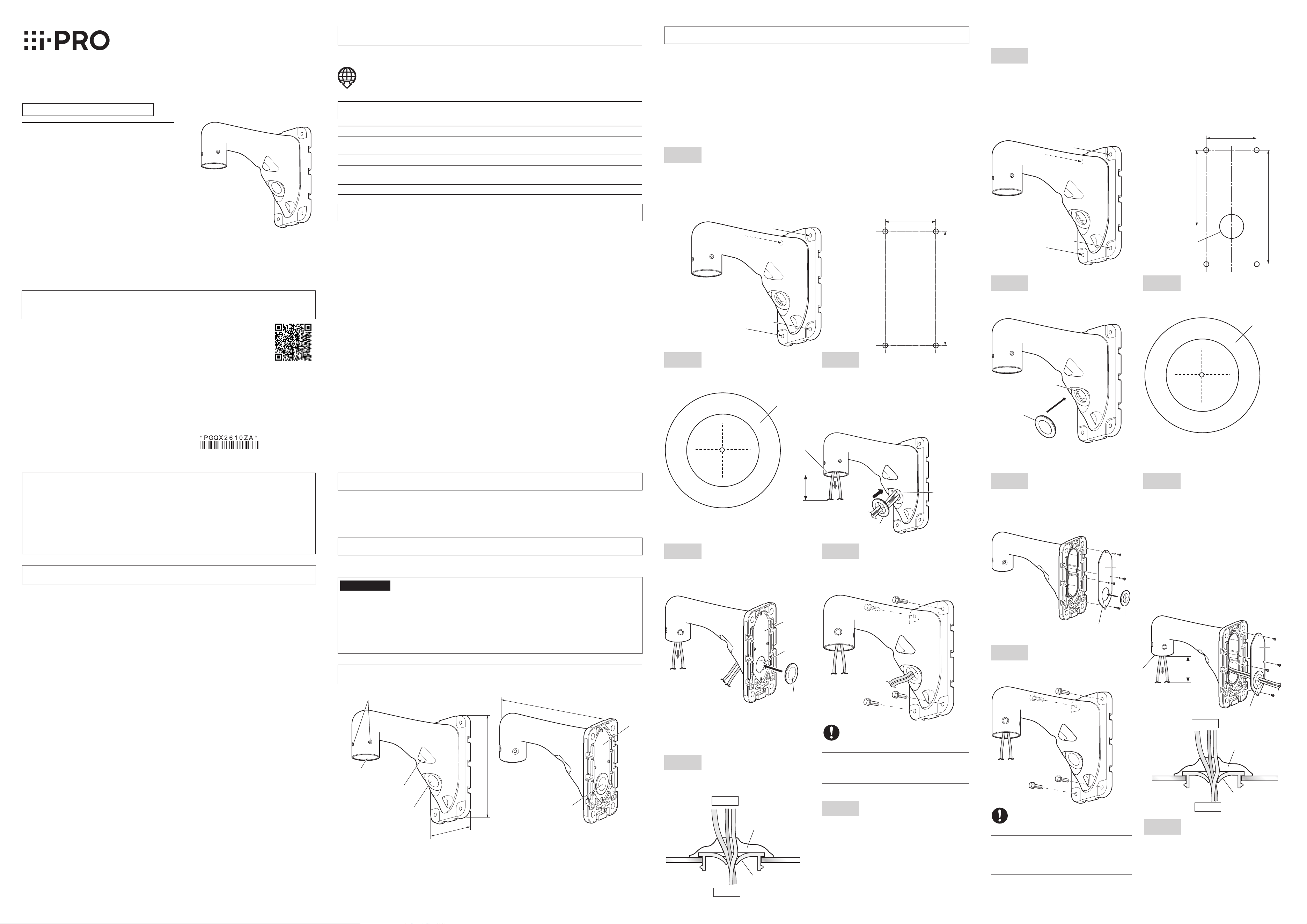
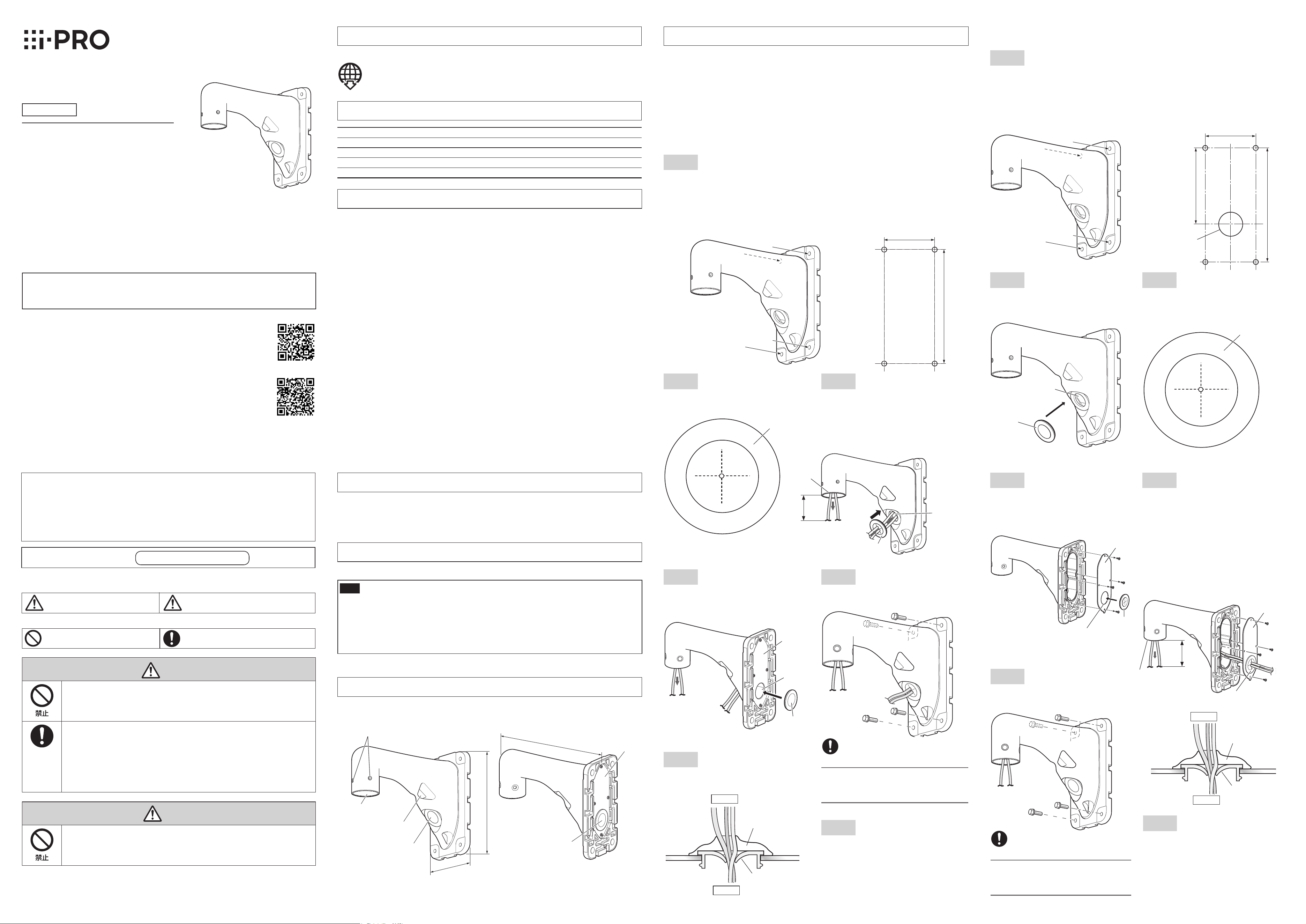
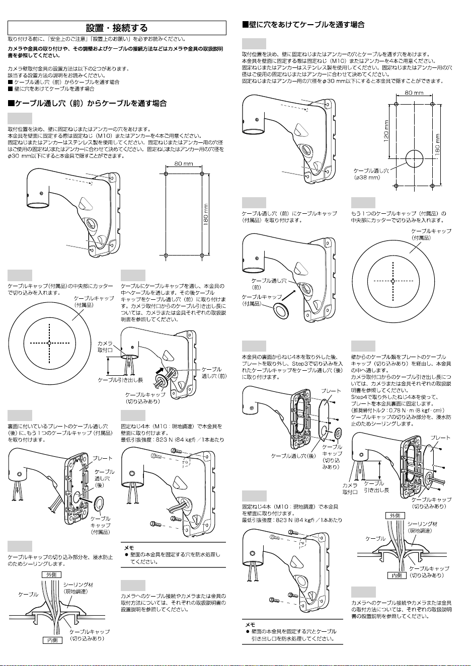
Installation/Connections
Be sure to read "Precautions" and "Precautions for installation" before installation.
Refer to the operating instructions of the camera or the bracket for details including the
camera or bracket mounting, their adjustment and the cable connection.
The installation of the wall mount bracket is roughly divided into 2 methods.
Refer to the applicable description.
When laying cables through the cable access hole (front)
When laying cables after drilling a hole through the wall
When laying cables through the cable access hole (front)
Step 1
Decide the mounting position and then drill holes for fixing screws or anchors in the wall.
Procure 4 pieces of M10 fixing screws or anchors to secure this product on the wall.
All fixing screws or anchors shall be stainless steel. The hole diameter for fixing screws or anchors
shall be decided in accordance with the fixing screws or anchors to be used. A hole on the wall with a
diameter of 30 mm {ø1-3/16 inches} or less for a fixing screw or an anchor can be hidden with this
product.
Hexagon screw hole for mounting camera
(4 places)
Wire hook section
Camera mounting part
Cable access hole (front)
Plate
Cable access hole
(rear)
220 mm {8-21/32 inches}
269
m
m
{
10-19/
32
i
n
che
s
}
1
20
m
m
{
4-2
3
/
32
i
n
c
hes
}
Step 2
Make a slit in the center of the cable cap
(accessory) with a cutter.
Cable cap
(accessory)
Step 3
Pass the cable cap through the cable and then
pass the cable into this product. Mount the
cable cap to the cable access hole (front).
Refer to each manual of the camera and the
bracket for further information about the length
of the cable to be pulled out from the camera
mounting part.
Step 2
Mount the cable cap (accessory) on the cable
access hole (front).
Step 3
Make a slit in the center of another cable cap
(accessory) with a cutter.
When laying cables after drilling a hole through the wall
Step 1
Decide the mounting position, and drill a hole for a fixing screw or an anchor and a hole for cable
installation in the wall.
Procure 4 pieces of M10 fixing screws or anchors to secure this product on the wall.
All fixing screws or anchors shall be stainless steel. The hole diameter for fixing screws or anchors
shall be decided in accordance with the fixing screws or anchors to be used.
A hole on the wall with a diameter of 30 mm {ø1-3/16 inches} or less for a fixing screw or an
anchor can be hidden with this product.
Step 6
Seal the slit of the cable cap for the prevention of
water leakage.
Outside
Inside
Cable
Sealant (locally procured)
Cable cap (with a slit)
Step 4
After removing the screws (4pcs.) from the rear
side of the bracket, remove the plate and
mount the cable cap in which a slit was made
in Step 3 on the cable access hole (rear).
Step 5
Pass the cables from the wall through the
cable cap (with a slit) on the plate and then
through this product.
Refer to each manual of the camera and the
bracket for further information about the length
of the cable to be pulled out from the camera
mounting part.
Secure the plate with the screws (4pcs.)
removed in Step 4 on the rear side of the
bracket.
(Recommended tightening torque: 0.78 N·m
{0.58 lbf·ft})
Seal the slit of the cable cap for the prevention
of water leakage.
Step 6
Mount this product on the wall with fixing
screws (4pcs.) (M10: locally procured).
Minimum pull-out strength: 823 N {185 lbf}/
per 1 pc.
Step 7
Refer to each manual of the camera and the
bracket for further information about cable
connection and how to install the camera or
the bracket.
80 mm
{3-5/32 inches}
180 mm
{7-3/32 inches}
Hole for cable
installation: ø38 mm
{ø1-1/2 inches}
80 mm
{3-5/32 inches}
180 mm
{7-3/32 inches}
120 mm
{4-23/32 inches}
Caution:
• Before attempting to connect or operate this
product, please read these instructions care-
fully.
Notice:
• This product is not suitable for use in loca-
tions where children are likely to be present.
• Do not install this product in locations where
ordinary persons can easily reach.
• For information about screws and other
parts required for installation, refer to the
corresponding section of this document.
Standard accessories
Operating Instructions (this document) ....................................................................................... 1 pc.
Cable cap .................................................................................................................................. 2 pcs.
Camera mounting screw (Hexagon screw (M6)) ......................................................................... 5 pcs.
(of them, 1 for spare)
Other items that are needed (not included)
Fixing screw (M10) or anchor ..................................................................................................... 4 pcs.
IMPORTANT
Minimum pullout strength: 823 N {185 lbf} (per 1 pc.)
Refer to our technical information website <ControlNo.: C0120> for information on the
minimum pull-out strength.
Select screws according to the material of the location that the camera will be mounted to.
In this case, wood screws and nails should not be used.
Parts and functions
Cable
access hole
(front)
Cable cap
(with a slit)
Camera
mounting
part
Length of cable
to be pulled
Step 7
Refer to each manual of the camera and the
bracket for further information about cable
connection and how to install the camera or the
bracket.
Cable
access
hole (rear)
Cable cap
(accessory)
Plate
Cable cap
(accessory)
Cable access hole
(front)
Cable cap
(accessory)
Outside
Inside
Cable
Sealant
(locally procured)
Cable cap (with a slit)
Cable cap (with a slit)
Length of cable
to be pulled
Camera
mounting
part
Plate
Plate
Cable cap
(with a slit)
Cable access
hole (rear)
Note:
• Apply a waterproofing to the holes for
fixing this product on the wall and the
cable inlet.
Note:
• Apply a waterproofing to the holes for fixing
this product on the wall.
© i-PRO Co., Ltd. 2023
avs1221-2013
Printed in China
https://www.i-pro.com/
Step 4
Mount another cable cap (accessory) on the
cable access hole (rear) on the plate on the rear
side of the bracket.
Step 5
Mount this product on the wall with fixing screws
(4pcs.) (M10: locally procured).
Minimum pull-out strength: 823 N {185 lbf}/
per 1pc.
Preface
This product is used for installing the network camera on a wall. For the latest
information about the supported cameras and brackets, refer to our technical
information website
(https://i-pro.com/global/en/surveillance/training-support/support/technical-information
<Control No.: C0501>).
The model number is abbreviated in some descriptions in this manual.
Specifications
Ambient operating temperature: –50 °C to +60 °C {–58 °F to 140 °F}
Dimensions:
120 mm (W) x 220 mm (H) x 269 mm (D)
{4-23/32 inches (W) x 8-21/32 inches (H) x 10-19/32 inches (D)}
Mass: Approx. 2 k
g
{4.42 lbs}
Finish: Aluminum die cast i-PRO white/ Black
Precautions for installation
In order to prevent injury, the product must be securely mounted to the wall according to
the installation guide of this bracket.
Mounting method for this product
This product is designed to be mounted on a wall. If it is mounted on a desktop or at a slant, the
camera may not work correctly and its lifetime may be shortened.
Make sure to remove this product if it will no longer be used.
Precaution
Do not use this product except with suitable cameras or brackets.
Failure to observe this may cause a drop resulting in injury.
Refer installation work to the dealer.
Installation work requires technique and experiences.
Failure to observe this may cause fire, electric shock, injury, or damage to the product.
Be sure to consult the dealer.
The measures of protection against snowfall shall be taken.
Weight of snow may cause a fall of the product resulting in injury or accidents.
Protect the product against snowfall by installing it under eaves.
Do not rub the edges of metal parts with your hand.
Strong rubbing may cause injury.
When using this product, also read the “Precautions” described in the operating instruc-
tions for the camera to be attached.
Operating Instructions
Included Installation Instructions
Wall Mount Bracket
Model No.
WV-QWL501
•
Before attempting to connect or install this product, please read these instructions carefully and
save this manual for future use.
• The external appearance and other parts shown in this manual may differ from the actual
product within the scope that will not interfere with normal use due to improvement of the
product.
i-PRO Co., Ltd. assumes no responsibility for injuries or property damage resulting
from failures arising out of improper installation or operation inconsistent with this
documentation.
Installation/Connections
Be sure to read "Precautions" and "Precautions for installation" before installation.
Refer to the operating instructions of the camera or the bracket for details including the
camera or bracket mounting, their adjustment and the cable connection.
The installation of the wall mount bracket is roughly divided into 2 methods.
Refer to the applicable description.
When laying cables through the cable access hole (front)
When laying cables after drilling a hole through the wall
When laying cables through the cable access hole (front)
Step 1
Decide the mounting position and then drill holes for fixing screws or anchors in the wall.
Procure 4 pieces of M10 fixing screws or anchors to secure this product on the wall.
All fixing screws or anchors shall be stainless steel. The hole diameter for fixing screws or anchors
shall be decided in accordance with the fixing screws or anchors to be used. A hole on the wall with a
diameter of 30 mm {ø1-3/16 inches} or less for a fixing screw or an anchor can be hidden with this
product.
Hexagon screw hole for mounting camera
(4 places)
Wire hook section
Camera mounting part
Cable access hole (front)
Plate
Cable access hole
(rear)
220 mm {8-21/32 inches}
269
m
m
{
10-19/
32
i
n
che
s
}
1
20
m
m
{
4-2
3
/
32
i
n
c
hes
}
Step 2
Make a slit in the center of the cable cap
(accessory) with a cutter.
Cable cap
(accessory)
Step 3
Pass the cable cap through the cable and then
pass the cable into this product. Mount the
cable cap to the cable access hole (front).
Refer to each manual of the camera and the
bracket for further information about the length
of the cable to be pulled out from the camera
mounting part.
Step 2
Mount the cable cap (accessory) on the cable
access hole (front).
Step 3
Make a slit in the center of another cable cap
(accessory) with a cutter.
When laying cables after drilling a hole through the wall
Step 1
Decide the mounting position, and drill a hole for a fixing screw or an anchor and a hole for cable
installation in the wall.
Procure 4 pieces of M10 fixing screws or anchors to secure this product on the wall.
All fixing screws or anchors shall be stainless steel. The hole diameter for fixing screws or anchors
shall be decided in accordance with the fixing screws or anchors to be used.
A hole on the wall with a diameter of 30 mm {ø1-3/16 inches} or less for a fixing screw or an
anchor can be hidden with this product.
Step 6
Seal the slit of the cable cap for the prevention of
water leakage.
Outside
Inside
Cable
Sealant (locally procured)
Cable cap (with a slit)
Step 4
After removing the screws (4pcs.) from the rear
side of the bracket, remove the plate and
mount the cable cap in which a slit was made
in Step 3 on the cable access hole (rear).
Step 5
Pass the cables from the wall through the
cable cap (with a slit) on the plate and then
through this product.
Refer to each manual of the camera and the
bracket for further information about the length
of the cable to be pulled out from the camera
mounting part.
Secure the plate with the screws (4pcs.)
removed in Step 4 on the rear side of the
bracket.
(Recommended tightening torque: 0.78 N·m
{0.58 lbf·ft})
Seal the slit of the cable cap for the prevention
of water leakage.
Step 6
Mount this product on the wall with fixing
screws (4pcs.) (M10: locally procured).
Minimum pull-out strength: 823 N {185 lbf}/
per 1 pc.
Step 7
Refer to each manual of the camera and the
bracket for further information about cable
connection and how to install the camera or
the bracket.
80 mm
{3-5/32 inches}
180 mm
{7-3/32 inches}
Hole for cable
installation: ø38 mm
{ø1-1/2 inches}
80 mm
{3-5/32 inches}
180 mm
{7-3/32 inches}
120 mm
{4-23/32 inches}
Caution:
• Before attempting to connect or operate this
product, please read these instructions care-
fully.
Notice:
• This product is not suitable for use in loca-
tions where children are likely to be present.
• Do not install this product in locations where
ordinary persons can easily reach.
• For information about screws and other
parts required for installation, refer to the
corresponding section of this document.
Standard accessories
Operating Instructions (this document) ....................................................................................... 1 pc.
Cable cap .................................................................................................................................. 2 pcs.
Camera mounting screw (Hexagon screw (M6)) ......................................................................... 5 pcs.
(of them, 1 for spare)
Other items that are needed (not included)
Fixing screw (M10) or anchor ..................................................................................................... 4 pcs.
IMPORTANT
Minimum pullout strength: 823 N {185 lbf} (per 1 pc.)
Refer to our technical information website <ControlNo.: C0120> for information on the
minimum pull-out strength.
Select screws according to the material of the location that the camera will be mounted to.
In this case, wood screws and nails should not be used.
Parts and functions
Cable
access hole
(front)
Cable cap
(with a slit)
Camera
mounting
part
Length of cable
to be pulled
Step 7
Refer to each manual of the camera and the
bracket for further information about cable
connection and how to install the camera or the
bracket.
Cable
access
hole (rear)
Cable cap
(accessory)
Plate
Cable cap
(accessory)
Cable access hole
(front)
Cable cap
(accessory)
Outside
Inside
Cable
Sealant
(locally procured)
Cable cap (with a slit)
Cable cap (with a slit)
Length of cable
to be pulled
Camera
mounting
part
Plate
Plate
Cable cap
(with a slit)
Cable access
hole (rear)
Note:
• Apply a waterproofing to the holes for
fixing this product on the wall and the
cable inlet.
Note:
• Apply a waterproofing to the holes for fixing
this product on the wall.
© i-PRO Co., Ltd. 2023
avs1221-2013
Printed in China
https://www.i-pro.com/
WV-QWL501
Step1
Step2 Step3
Step2 Step3
Step1
Step6
Step4 Step5
Step6
Step7
220 mm
269
m
m
1
20
m
m
Step7
Step4 Step5
https://www.i-pro.com/
WV-QWL501
Step1
Step2 Step3
Step2 Step3
Step1
Step6
Step4 Step5
Step6
Step7
220 mm
269
m
m
1
20
m
m
Step7
Step4 Step5
https://www.i-pro.com/