Loading ...
Loading ...
Loading ...
A
B
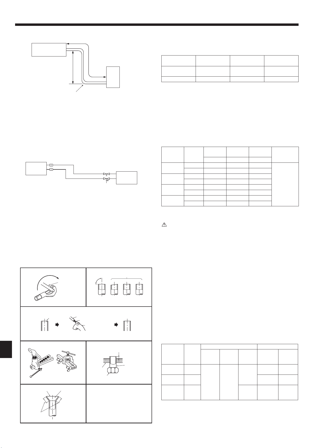
4. Refrigerant piping work
4.1. Refrigerant pipe (Fig. 4-1, Fig. 4-2)
► Check that the difference between the heights of the indoor and outdoor
units, the length of refrigerant pipe, and the number of bends in the pipe are
within the limits shown below.
Models
A Pipe length
(one way)
B Height
difference
C Number of
bends (one way)
SUZ-KA09, KA12,
KA15
Max. 65 ft (20 m) Max. 40 ft (12 m) Max. 10
SUZ-KA18 Max. 100 ft (30 m) Max. 50 ft (15 m) Max. 10
• Height difference limitation is dened regardless of which unit, indoor or outdoor,
is positioned higher.
• Refrigerant adjustment ... No additional charge is required.
• Table below shows the specications of pipes commercially available.
Model Pipe
Outside
diameter
Min. wall
thickness
Insulation
thickness
Insulation
material
inch (mm) inch (mm) inch (mm)
SUZ-KA09
For liquid 1/4 (6.35) 0.0315 (0.8) 5/16 (8)
Heat resisting
foam plastic
0.045 specic
gravity
For gas 3/8 (9.52) 0.0315 (0.8) 5/16 (8)
SUZ-KA12
For liquid 1/4 (6.35) 0.0315 (0.8) 5/16 (8)
For gas 3/8 (9.52) 0.0315 (0.8) 5/16 (8)
SUZ-KA15
For liquid 1/4 (6.35) 0.0315 (0.8) 5/16 (8)
For gas 1/2 (12.7) 0.0315 (0.8) 5/16 (8)
SUZ-KA18
For liquid 1/4 (6.35) 0.0315 (0.8) 5/16 (8)
For gas 1/2 (12.7) 0.0315 (0.8) 5/16 (8)
• To prevent condensation, insulate the 2 refrigerant pipes.
• Refrigerant pipe bending radius must be 4 in. (100 mm) or more
Caution:
Be sure to use the insulation of specied thickness (table on the above). Excessive
insulation may cause incorrect installation of the indoor unit, and too little insulation
may cause condensate to form.
• The unit has ared connections on both indoor and outdoor sides.
• Remove the valve cover from the outdoor unit, then connect the pipe.
• Refrigerant pipes are used to connect the indoor and outdoor units.
• Be careful not to crush or over bend the pipe in pipe bending.
A
D
B
C
E
Fig. 4-1
D Indoor unit
E Outdoor unit
A Indoor unit
B Outdoor unit
4.2. Flaring work (Fig. 4-3)
1) Cut the cooper pipe as straight as possible with a pipe cutter.
2) Remove all burrs from the cut section of pipe, ensuring that precautions are taken
to avoid getting metal shavings into the piping.
3) Remove are nuts attached to indoor and outdoor units, then put them on pipe.
4) Flaring work. Firmly hold copper pipe in the dimension shown in the table. Select
A inch (mm) from the table according to the tool you use.
5) Check
• Compare the ared work.
•
If are is defective, cut off the section and repeat procedure.
Pipe diameter
inch (mm)
Nut
inch (mm)
A inch (mm) Tightening torque
Clutch
type tool
for R410A
Clutch
type tool
for R22
Wing nut
type tool
for R22
N·m
ft·lb
(kgf·cm)
1/4 (6.35) 1/4 (17)
0 to 0.02
(0 to 0.5)
0.04 to
0.06
(1.0 to 1.5)
0.06 to
0.08
(1.5 to 2.0)
13.7 to 17.7
10 to 13
(140 to 180)
3/8 (9.52) 3/8 (22)
34.3 to 41.2
25 to 30
(350 to 420)
1/2 (12.7) 1/2 (26)
0.08 to
0.10
(2.0 to 2.5)
49.0 to 56.4
36 to 42
(500 to 575)
90°
A
Fig. 4-3
Copper
pipe
Good No good
Tilted
Uneven
Burred
Burr
Copper pipe
Spare reamer
Pipe cutter
Flaring tool
Clutch type Wing nut type
Die
Copper pipe
Flare nut
Smooth all around
Inside is shining
without any
scratches.
Even length all
around
Fig. 4-2
ø1/2 (12.7)
ø3/8 (9.52)
ø1/4 (6.35)
inch (mm)
en
3
A_VG79Y103H02_EN.indd 3 2019/10/03 10:56:54
004
Loading ...
Loading ...
Loading ...