
March 2014
PN 4427817
© 2014 Fluke Corporation. All rights reserved.
All product names are trademarks of their respective companies.
1523, 1524
Thermometer Readout
1.888.610.7664 sales@GlobalTestSupply.com
Fluke-Direct.com

LIMITED WARRANTY AND LIMITATION OF LIABILITY
This Fluke product will be free from defects in material and workmanship for one year from the date of purchase. This
warranty does not cover fuses, disposable batteries, or damage from accident, neglect, misuse, alteration, contamination, or
abnormal conditions of operation or handling. Resellers are not authorized to extend any other warranty on Fluke’s behalf.
To obtain service during the warranty period, contact your nearest authorized service center to obtain return authorization
information, then send the product to that Service Center with a description of the problem.
THIS WARRANTY IS YOUR ONLY REMEDY. NO OTHER WARRANTIES, SUCH AS FITNESS FOR A PARTICULAR
PURPOSE, ARE EXPRESSED OR IMPLIED. FLUKE IS NOT LIABLE FOR ANY SPECIAL, INDIRECT, INCIDENTAL OR
CONSEQUENTIAL DAMAGES OR LOSSES, ARISING FROM ANY CAUSE OR THEORY. Since some states or countries
do not allow the exclusion or limitation of an implied warranty or of incidental or consequential damages, this limitation of
liability may not apply to you.
11/99
1.888.610.7664 sales@GlobalTestSupply.com
Fluke-Direct.com

i
Table of Contents
1 Before You Start .......................................................................1
1.1 Introduction ............................................................................................... 1
1.2 Standard Equipment ................................................................................. 1
1.3 Safety Information ..................................................................................... 2
1.3.1 Warning .....................................................................................................2
1.3.2 Cautions ..........................................................................................................3
1.4 CE Comments ........................................................................................... 5
1.4.1 EMC Directive .................................................................................................5
1.4.2 Immunity Testing .............................................................................................5
1.5 Using Clamp-On Ferrites .......................................................................... 5
1.6 Emissions Testing ..................................................................................... 6
1.7 Low Voltage Directive (Safety) .................................................................. 6
1.8 Authorized Service Centers ...................................................................... 7
2 Quick Start ................................................................................9
2.1 Setup ......................................................................................................... 9
2.2 Specifications ......................................................................................... 24
1.888.610.7664 sales@GlobalTestSupply.com
Fluke-Direct.com

1523, 1524 Thermometer Readout
ii
Figures
Figure 1 Clamp-On Ferrite ................................................................................. 6
Figure 2 Input/Output Connections - 1523 ........................................................ 9
Figure 3 Input/Output Connections - 1524 ...................................................... 10
Figure 4 Keys ................................................................................................... 11
Figure 5 1523 Menu ......................................................................................... 14
Figure 6 1523 Menu (cont) ............................................................................. 15
Figure 7 1523 Menu (cont) ............................................................................. 16
Figure 8 1524 Menu ........................................................................................ 19
Figure 9 1524 Menu (cont) ............................................................................. 20
Figure 10 1524 Menu (cont) ........................................................................... 21
Figure 11 1524 Menu (cont) ........................................................................... 22
Figure 12 1524 Menu (cont) ........................................................................... 23
Figure 13 1524 Menu (cont) ........................................................................... 24
1.888.610.7664 sales@GlobalTestSupply.com
Fluke-Direct.com

iii
Tables
Table 1 International Symbols ............................................................................ 4
Table 2 1523 Input/Output Connections ............................................................ 9
Table 3 1524 Input/Output Connections .......................................................... 10
Table 4 1523 Key Functions ............................................................................. 12
Table 5 1524 Key Functions ............................................................................. 17
Table 6 General Specifications ........................................................................ 24
Table 7 Millivolt Measurement .......................................................................... 25
Table 8 Ohms Measurement, RTDs ................................................................. 25
Table 9 Ohms Measurement, Thermistor ......................................................... 26
Table 10 Temperature, Thermocouples ........................................................... 26
Table 11 Temperature, RTD Ranges, and Accuracies (ITS-90) ....................... 28
Table 12 Temperature, Thermistor ................................................................... 28
1.888.610.7664 sales@GlobalTestSupply.com
Fluke-Direct.com

Before You Start
Standard Equipment
1
Before You Start1
Introduction1.1
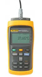
The Reference Thermometer Readouts (1523, 1524) are designed to be reliable, stable, temperature measur-
ing instruments that can be used in the eld or laboratory. They offer accuracy, portability, and speed for near-
ly every eld calibration application. The instruments have been designed with the eld user in mind and are
easy to use while maintaining stability, uniformity, and accuracy comparable to some laboratory instruments.
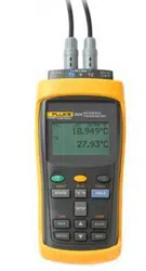
Your Fluke 1523 and 1524 thermometer readout is a handheld, battery operated instrument that measures tem-
perature using Platinum resistance Thermometers (PRT), Thermistors, and Thermocouples (TC).
Standard Equipment1.2
Unpack the instrument carefully and inspect it for any damage that may have occurred during shipment. If
there is shipping damage, notify the carrier immediately.
Verify that the following components are present:
1523/1524 Reference Thermometer Readout with 3 AA batteries
●●
AC Adapter, with power cord
●●
RS-232 Cable
●●
User’s Guide
●●
Documentation CD
●●
Report of Calibration and calibration label
●●
Clamp-on ferrite(s)
●●
If all items are not present, contact an Authorized Service Center. (See Section 1.8, Authorized Service Cen-
ters on page 7.)
1.888.610.7664 sales@GlobalTestSupply.com
Fluke-Direct.com

1523, 1524 Thermometer Readout
Safety Information
2
Safety Information1.3
The Reference Thermometer is designed in accordance with EN 61010-1 {2nd Edition}, and CAN/CSA 22.2
No 61010.1-04. Use this instrument only as specied in this manual, otherwise the protection provided by the
instrument may be impaired.
A Warning identies conditions and actions that pose hazard(s) to the user; a Caution identies conditions
and actions that may damage the instrument being used.
International symbols used on the reference thermometer and in this manual are explained in Table 1 on page
4.
1.3.1 Warning
To avoid possible electric shock or personal injury:
Do not use the reference thermometer in environments other than those listed in the user’s guide.
●●
Do not use the reference thermometer for any application other than that which is specied. The
●●
instrument was designed for temperature measurement and calibration. Any other use of the instrument
may cause unknown hazards to the user.
If the reference thermometer is used in a manner not in accordance with the equipment design, the
●●
operation and the protection provided by the instrument may be impaired. In addition, safety hazards
may arise.
Do not apply more than the rated voltage, as marked on the reference thermometer, between the inputs,
●●
or between any input and earth ground (30 V, 24 mA max all terminals).
Follow all equipment safety procedures.
●●
Calibration equipment should only be used by trained personnel.
●●
The reference thermometer is intended for indoor use only.
●●
Before you use the instrument, inspect the case. Look for cracks or missing plastic. Pay particular
●●
attention to the insulation surrounding the connectors. Do not use the reference thermometer if it
1.888.610.7664 sales@GlobalTestSupply.com
Fluke-Direct.com

Before You Start
Safety Information
3
appears damaged or operates abnormally. Protection may be impaired. When in doubt, have the
instrument serviced.
Always use an isolated RTD or PRT (metal sheath isolated from lead wires).
●●
Make sure the battery door is closed and latched before you operate the reference thermometer.
●●
Do not operate the reference thermometer around explosive gas, vapor, or dust.
●●
For battery operation use only 3 AA batteries, properly installed in the reference thermometer case.
●●
1524 model, thermocouples can only be used on channel 1.
●●
Cautions1.3.2
To avoid possible damage to the reference thermometer or to equipment under test:
Do not apply more than the rated voltage, as marked on the reference thermometer, between the inputs,
●●
or between any input and earth ground (30 V 24 mA max all terminals).
Unless recalibrating the instrument DO NOT change the values of the calibration constants from
●●
the factory set values. The correct setting of these parameters is important to the safety and proper
operation of the instrument.
The instrument and any thermometer probes used with it are sensitive instruments that can be easily
●●
damaged. Always handle these devices with care. DO NOT allow them to be dropped, struck, stressed,
or overheated.
DO NOT operate this instrument in an excessively wet, oily, dusty, or dirty environment.
●●
Use the proper probes, function and range for your measurement.
●●
Ensure probe coefcients are downloaded.
●●
1.888.610.7664 sales@GlobalTestSupply.com
Fluke-Direct.com
1523, 1524 Thermometer Readout
Safety Information
4
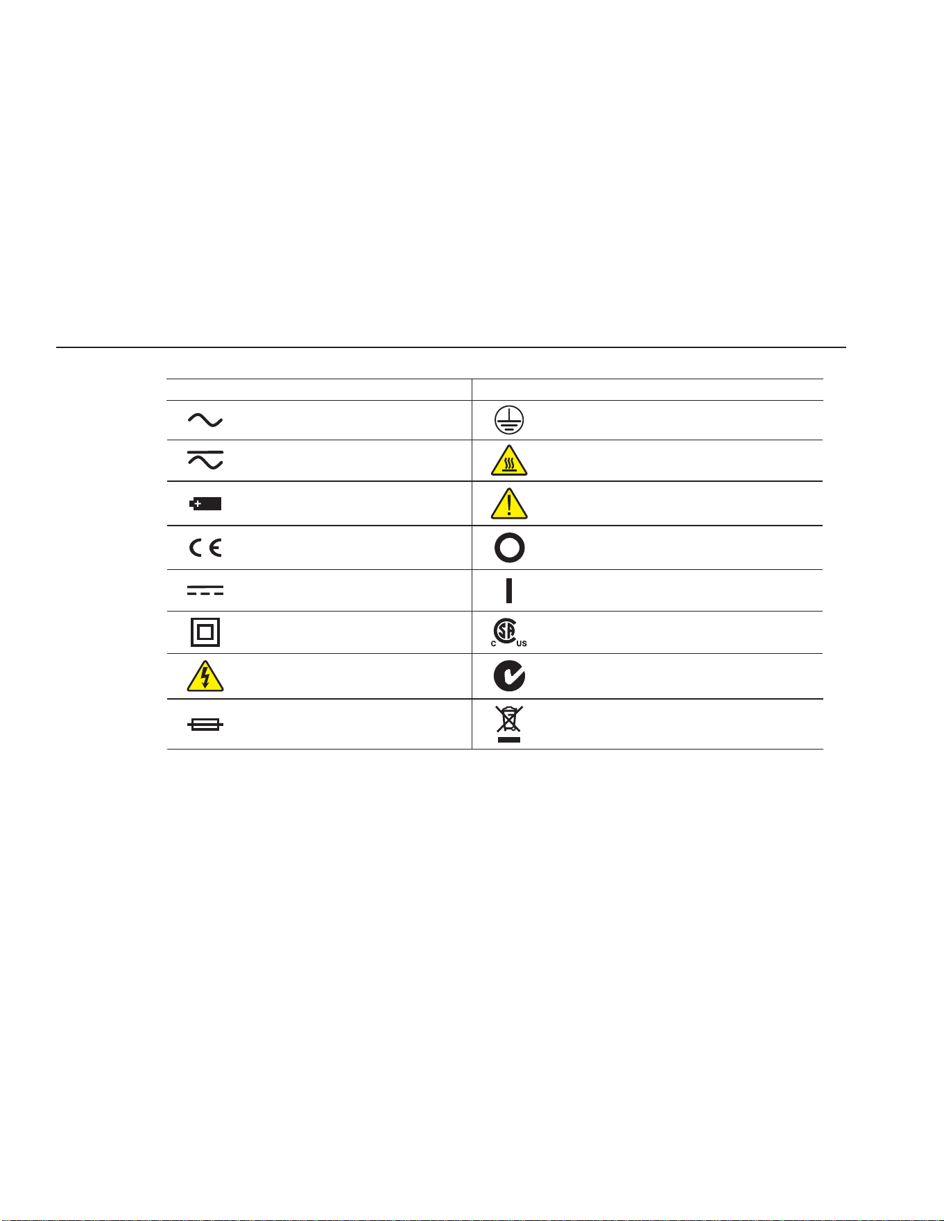
Table 1 International Symbols
Symbol Description Symbol Description
AC (Alternating Current) PE Ground
AC-DC Hot Surface (Burn Hazard)
Battery Read the User’s Guide (Important Information)
Complies with European Union directives Off
DC On
Double Insulated Canadian Standards Association
Electric Shock C-TICK Australian EMC mark
Fuse
The European Waste Electrical and Electronic
Equipment (WEEE) Directive (2002/96/EC) mark.
1.888.610.7664 sales@GlobalTestSupply.com
Fluke-Direct.com

Before You Start
Using Clamp-On Ferrites
5
CE Comments1.4
EMC Directive1.4.1
Fluke’s equipment has been tested to meet the European Electromagnetic Compatibility Directive (EMC
Directive, 2004/108/EC ). The Declaration of Conformity for your instrument lists the specific stan-dards
to which the unit was tested.
The instrument was designed specically as a test and measuring device. Compliance to the EMC direc-
tive is through EN 61326-1:2006 Electrical equipment for measurement, control and laboratory use – EMC
requirements
As noted in the EN 61326-1, the instrument can have varying congurations. The instrument was tested in a
typical conguration with shielded RS-232 cables.
Immunity Testing1.4.2
The instrument was tested to the requirements for laboratory locations.
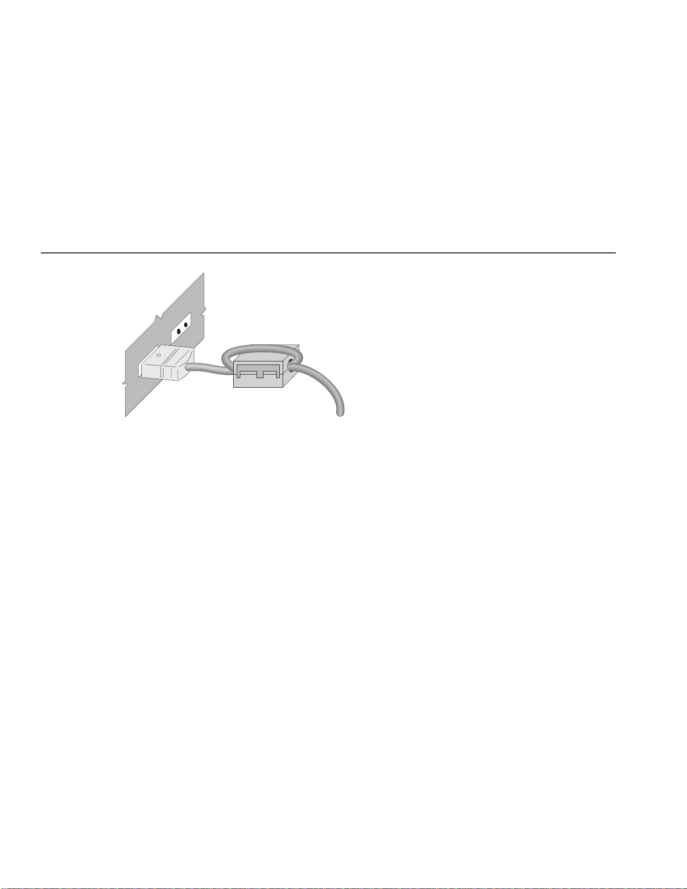
Using Clamp-On Ferrites1.5
Clamp-on ferrites are provided for use in improving the instrument’s electromagnetic (EM) immunity in envi-
ronments of excessive EM interference, like areas of heavy industrial equipment. We recommend placing the
ferrites on the cables of probes attached to the instrument.
To attach a ferrite to a probe cable, make a loop in the cable near the connector and clamp the ferrite around
half of the loop as shown in the diagram. The ferrite can be easily detached and moved to a new probe when
needed. (See Figure 1 on next page.)
1.888.610.7664 sales@GlobalTestSupply.com
Fluke-Direct.com
1523, 1524 Thermometer Readout
Emissions Testing
6
Figure 1
clamp-on ferrite
probe cable
Clamp-On Ferrite
Emissions Testing1.6
The instrument fullls the limit requirements for Class B.
Low Voltage Directive (Safety)1.7
In order to comply with the European Low Voltage Directive (2006/95/EC), Fluke equipment has been de-
signed to meet the EN 61010-1.
1.888.610.7664 sales@GlobalTestSupply.com
Fluke-Direct.com
Quick Start
Setup
9
Quick Start2
Setup2.1
SAVE
NEXT
HOME
ENTER
RESET TREND
RECALL
HOLDSTATS
°
C
°
F
SETUP
mV
RS
232
12
V DC
30
V MAX
1523
CALIBRATION
THERMOMETER
READOUT
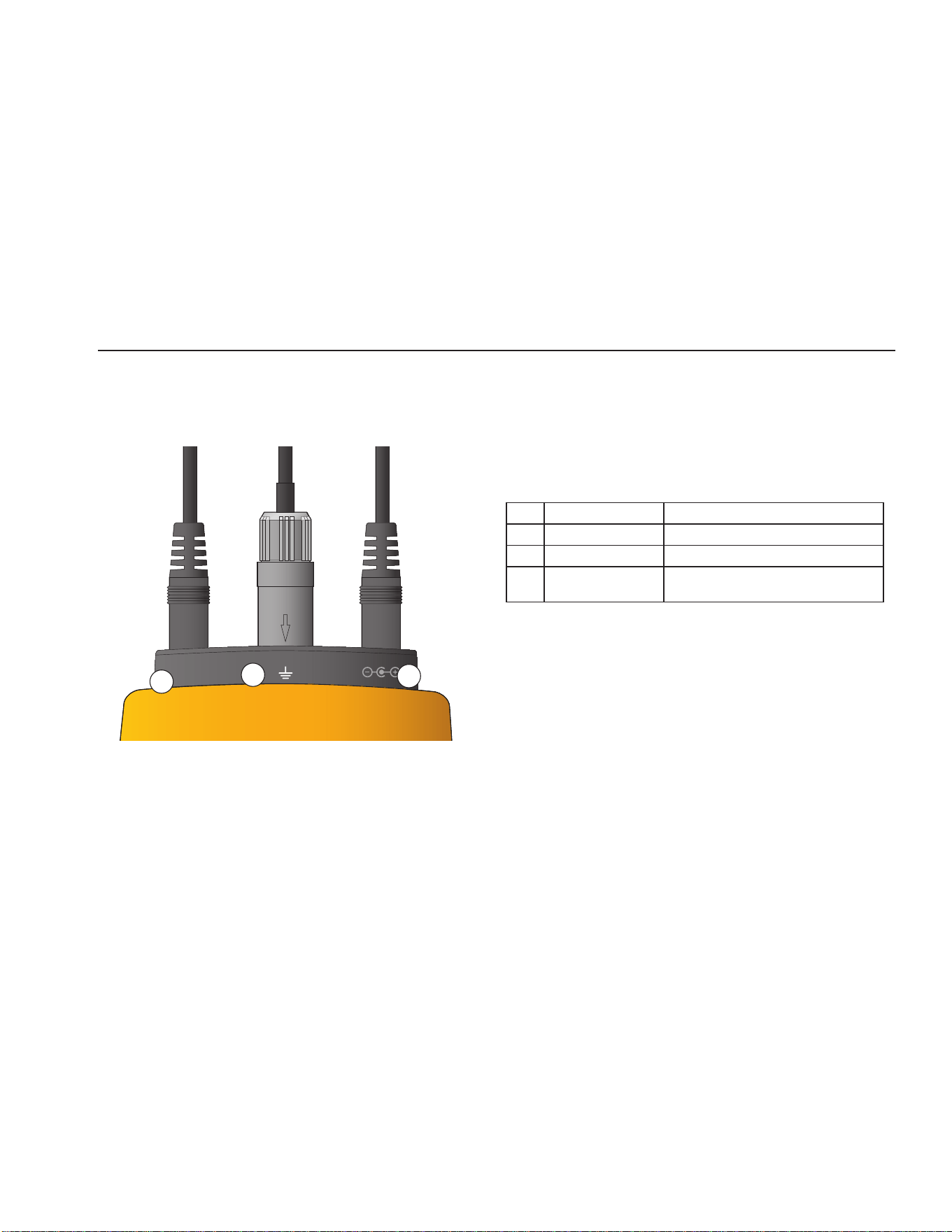
Figure 2 Input/Output Connections - 1523
1523 Input/Output ConnectionsTable 2
No. Name Description
1 Serial Serial interface connector
2 Connector, T1 Sensor Connector, Channel 1
4 Power External Power adapter connection
1
2
4
1.888.610.7664 sales@GlobalTestSupply.com
Fluke-Direct.com
1523, 1524 Thermometer Readout
Setup
10
SAVE
NEXT
HOMELOG
RESET
ENTER
RECALL
HOLDSTATS
°
C
°
F
SETUP
TRENDmV
RS232
12
V DC
30 V MAX
T1 T2
1524
CALIBRATION
THERMOMETER
READOUT
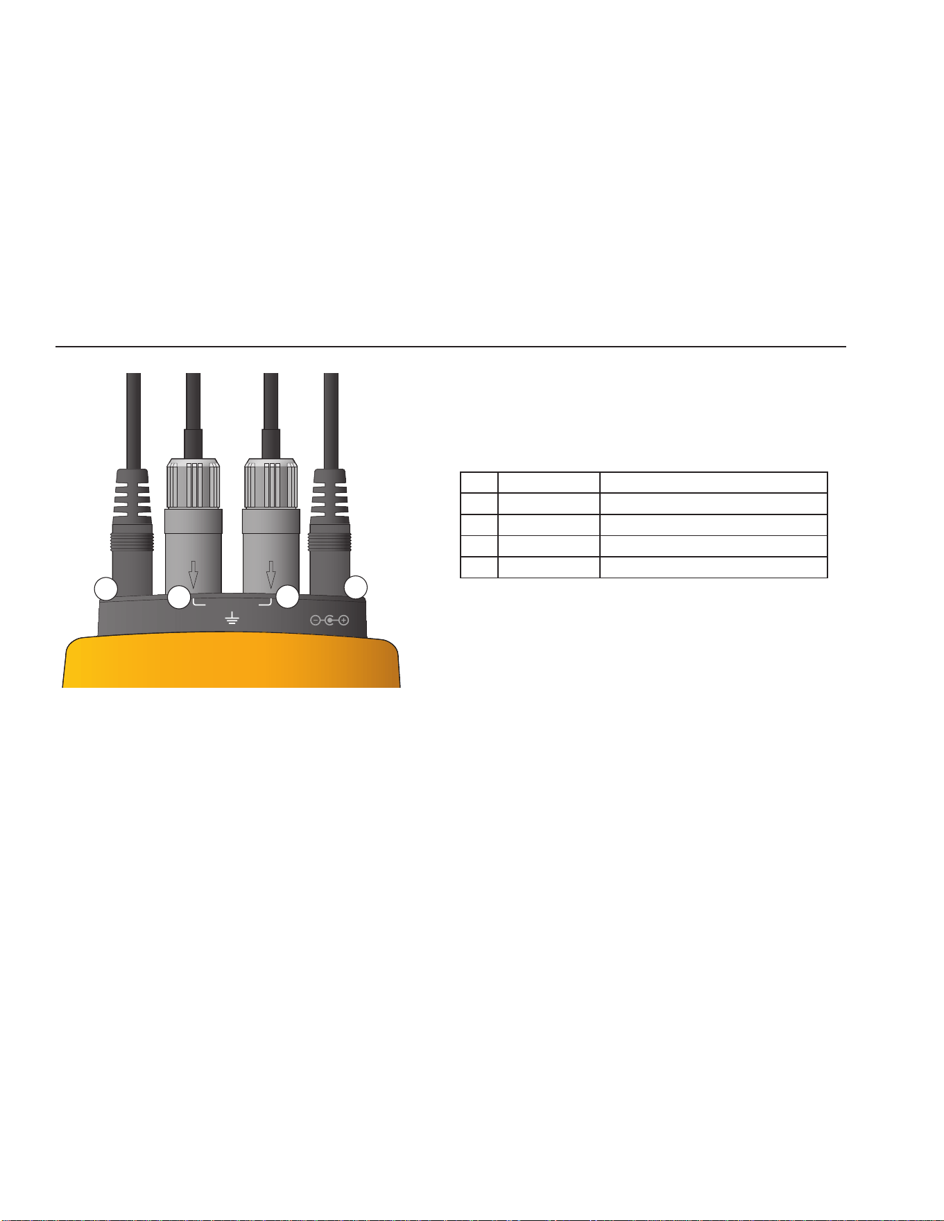
Figure 3 Input/Output Connections - 1524
1524 Input/Output ConnectionsTable 3
No Name Description
1 Serial Serial interface connector
2 Connector, T1 Sensor Connector, Channel 1
3 Connector, T2 Sensor Connector, Channel 2
4 Power External Power adapter connection
1
2
4
3
1.888.610.7664 sales@GlobalTestSupply.com
Fluke-Direct.com
Quick Start
Setup
11
SAVE
NEXT
HOMELOG
RESET
ENTER
RECALL
HOLDSTATS
°
C
°
F
SETUP
TRENDmV
RS232
12
V DC
30 V MAX
T1 T2
1524
CALIBRATION
THERMOMETER
READOUT
1
10
11
4
3
2
5
6
7
8
9
12
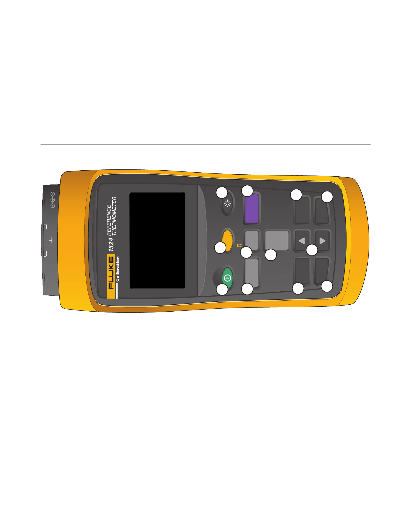
Figure 4 Keys
1.888.610.7664 sales@GlobalTestSupply.com
Fluke-Direct.com
1523, 1524 Thermometer Readout
Setup
12
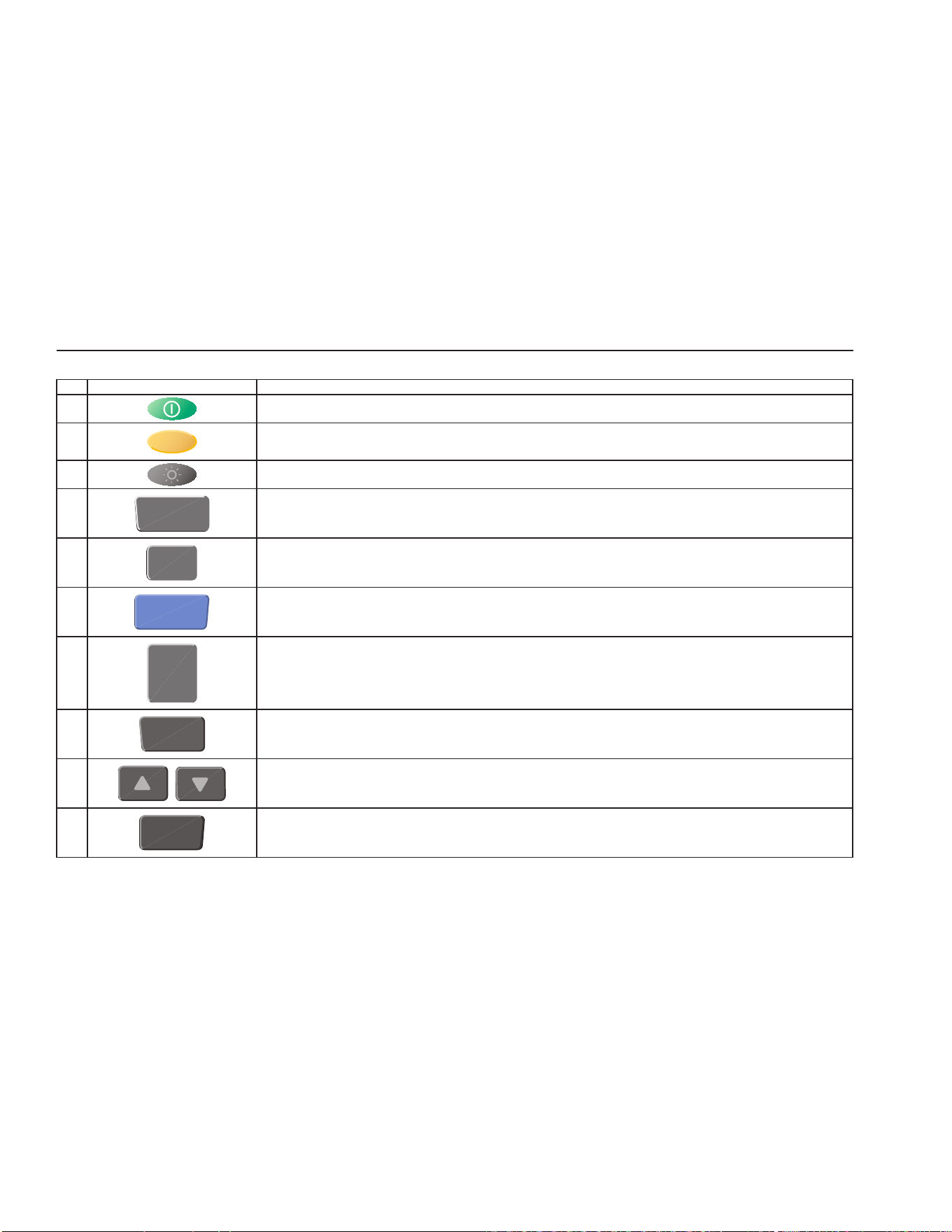
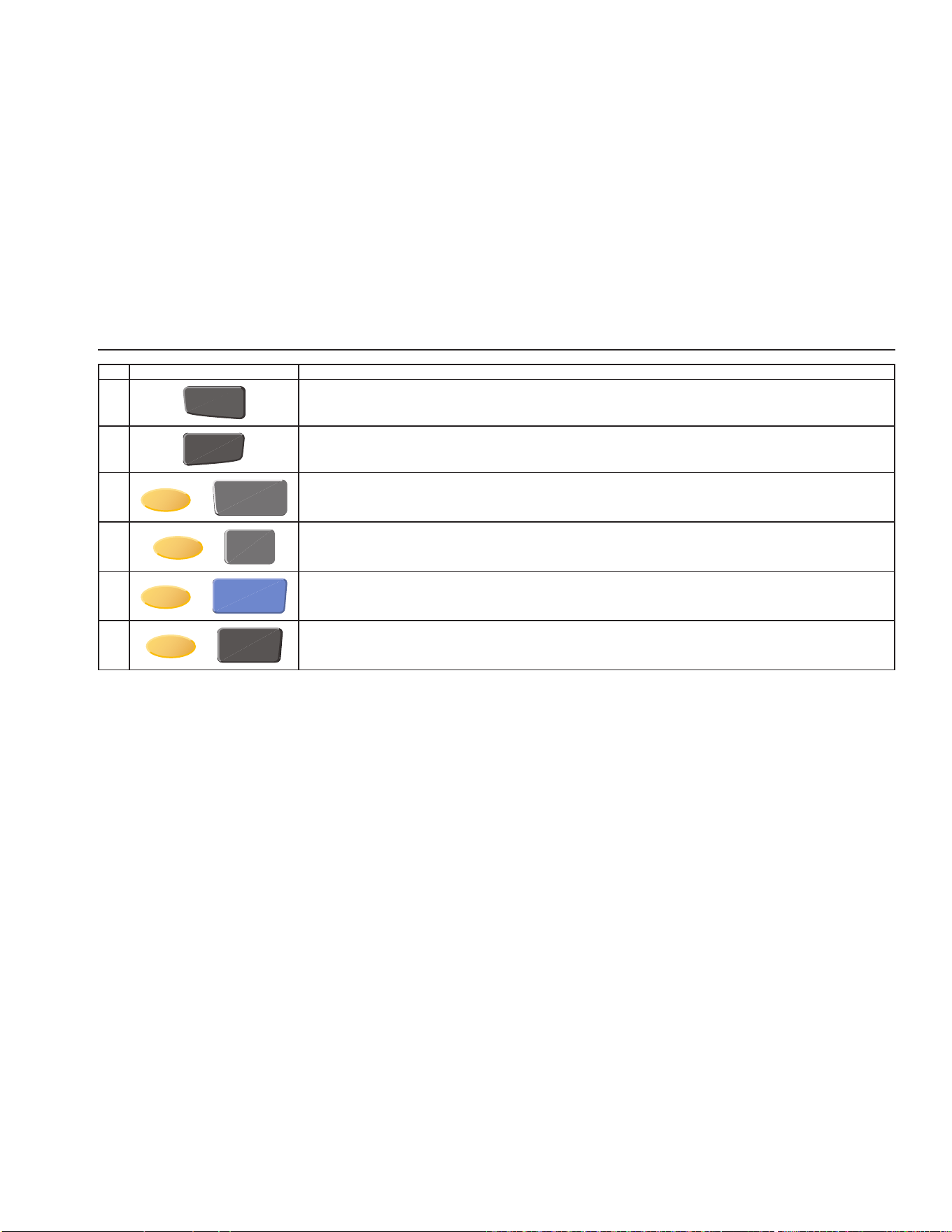
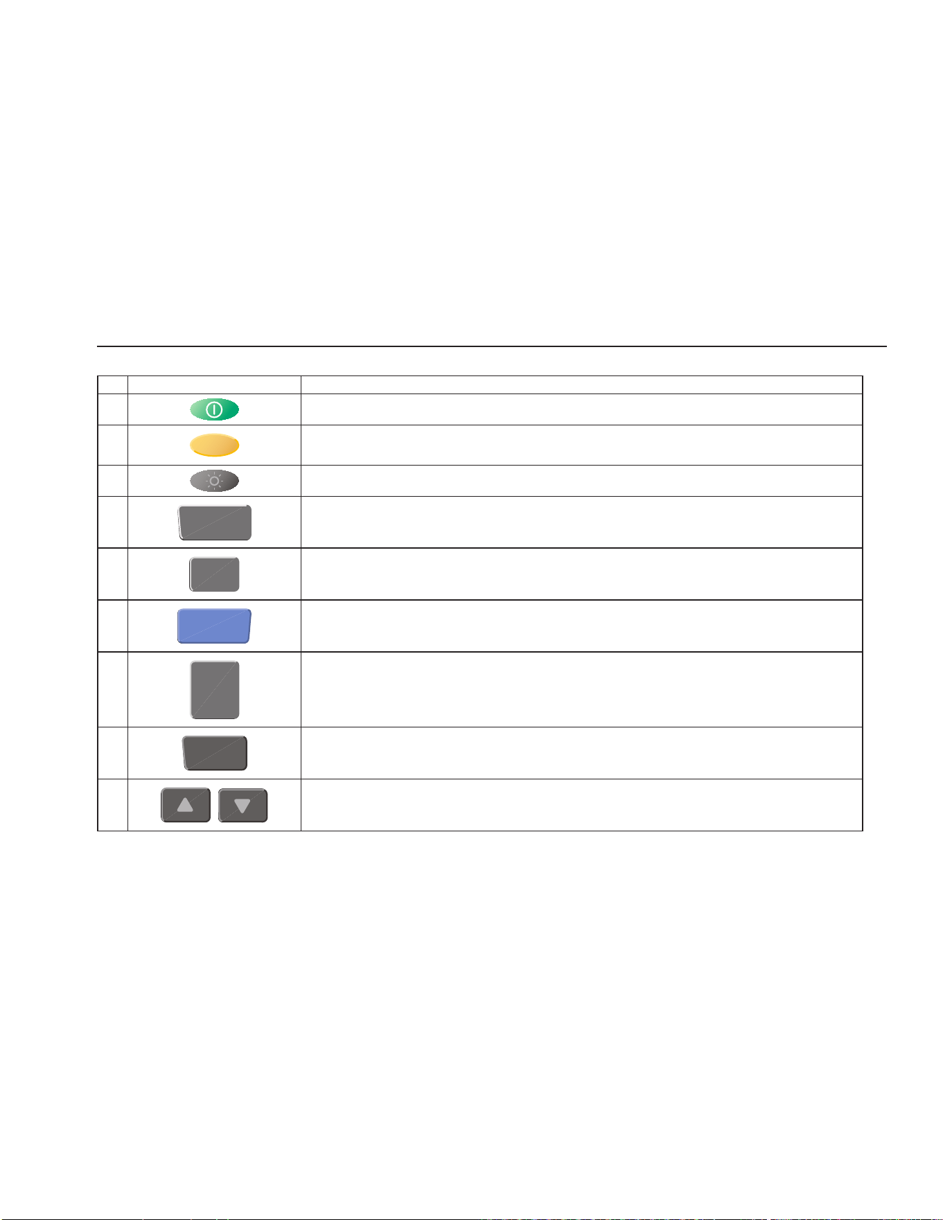
1523 Key FunctionsTable 4
No Key Description
1
Power on or off
2
Yellow Second or Special Function Key
3
Turns the backlight on or off
4
STATS
1st Press: MAX, 2nd Press: MIn, 3rd Press: AVE, 4th Press: STD DEV
5
°
C
°
F
Units, °C/°F
6
HOLD
1st press - Holds value on screen "-- HOLD --" across bottom of screen. 2nd press - Releases Screen hold.
7
SETUP
Enters setup menu, see menu structure
8
SAVE
Saves measurement as a logged data point
9
Arrows increment or decrement selections in an active field. In Graph Mode, Arrows change the scale of the graph.
10
ENTER
Selects highlighted selection, Saves a new selection.
1.888.610.7664 sales@GlobalTestSupply.com
Fluke-Direct.com
Quick Start
Setup
13
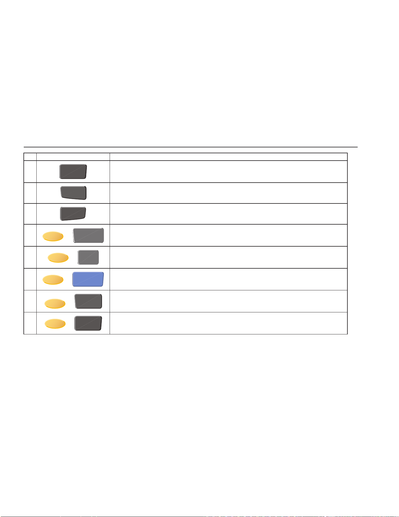
No Key Description
11
RECALL
1st Press - Enters Recall menu, 2nd Press - Exits Recall Menu
12
NEXT
Moves down to next option on screen.
13
+
STATS
“RESET” - Resets Stats Data
14
+
°
C
°
F
“Ω mV” - Toggles from °C to Ω or Ω to °C (PRT, thermistor), °C to mV or mV to °C (TC)
15
+
HOLD
“TREND” - Starts Graphing data
16
+
ENTER
“HOME” Returns user to main screen
1.888.610.7664 sales@GlobalTestSupply.com
Fluke-Direct.com
1523, 1524 Thermometer Readout
Setup
14
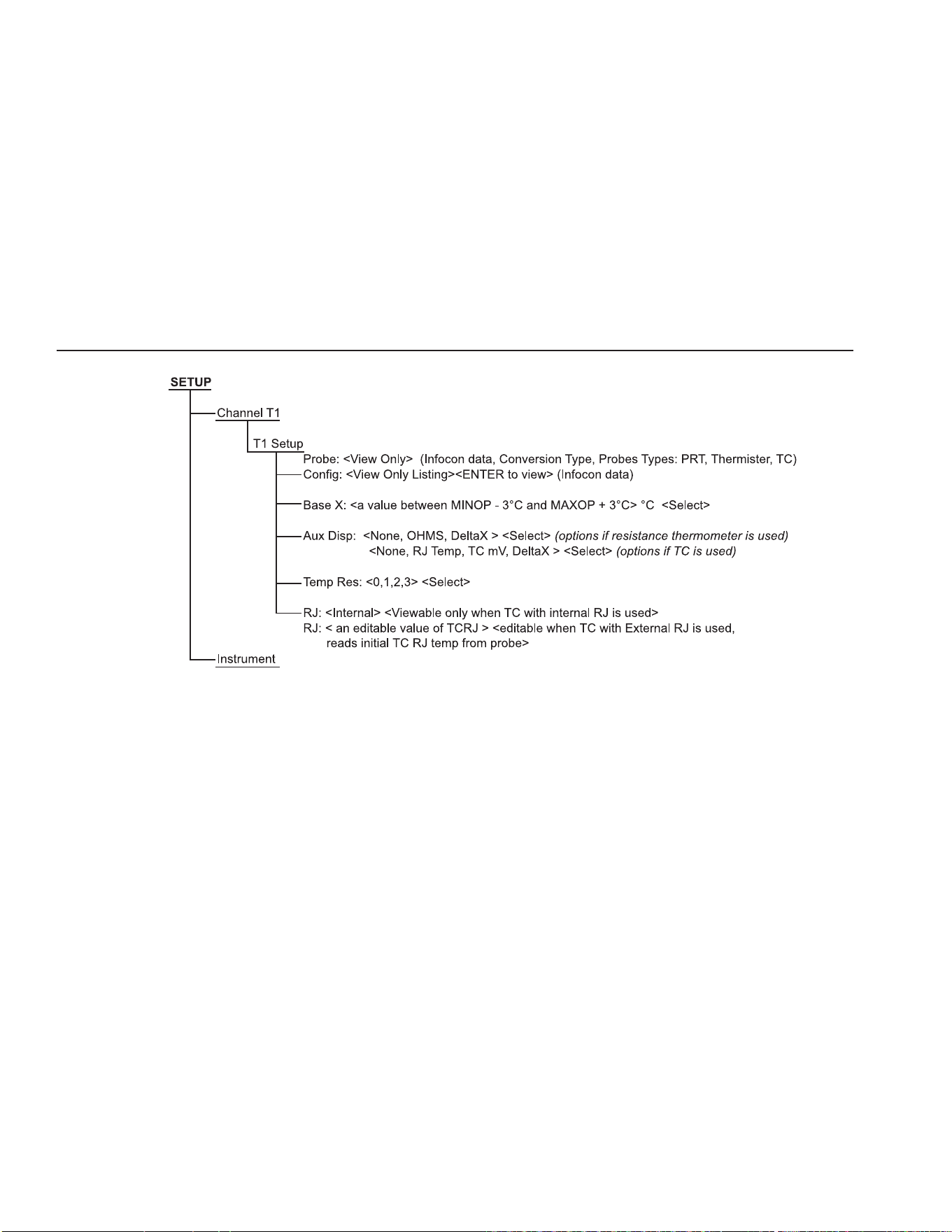
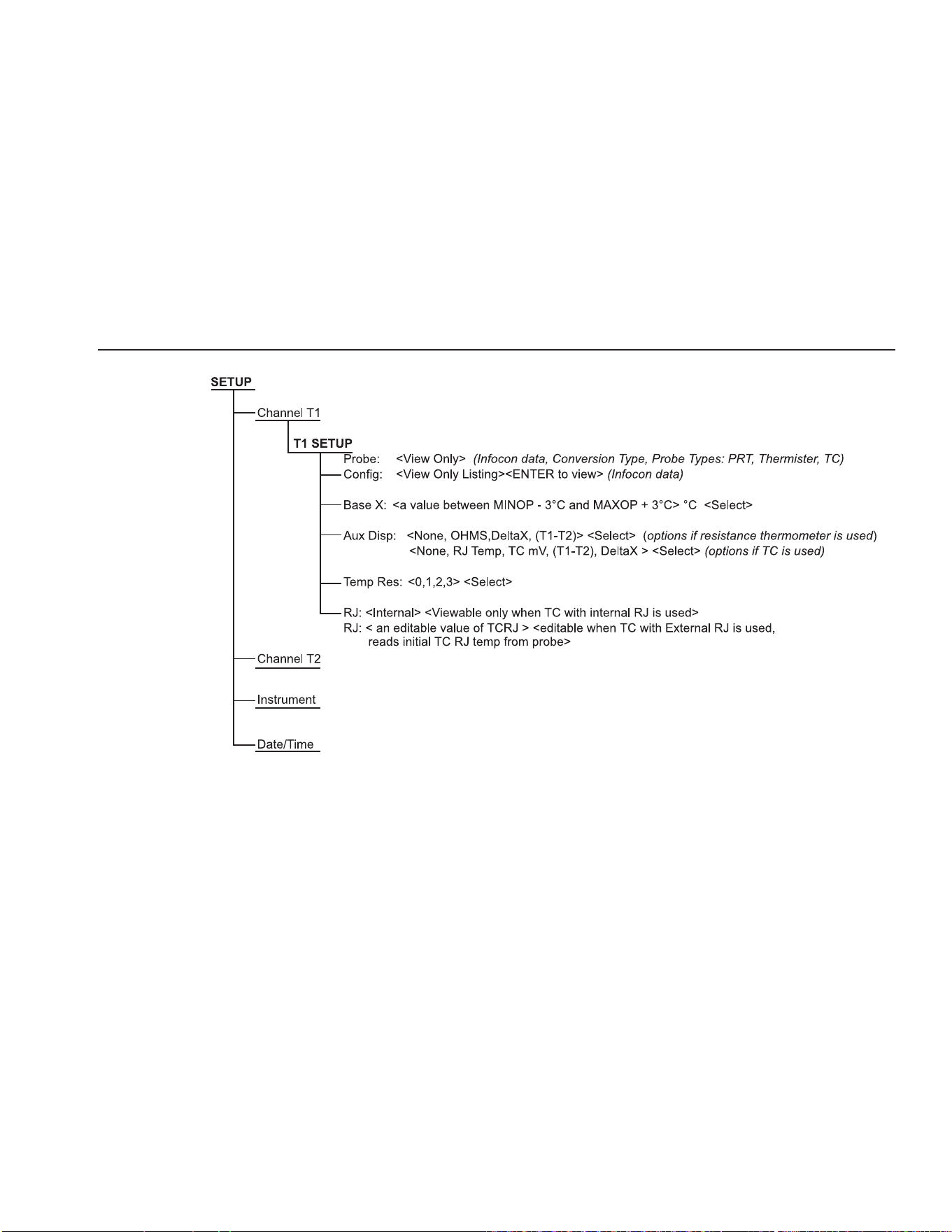
Figure 5 1523 Menu
1.888.610.7664 sales@GlobalTestSupply.com
Fluke-Direct.com
Quick Start
Setup
15
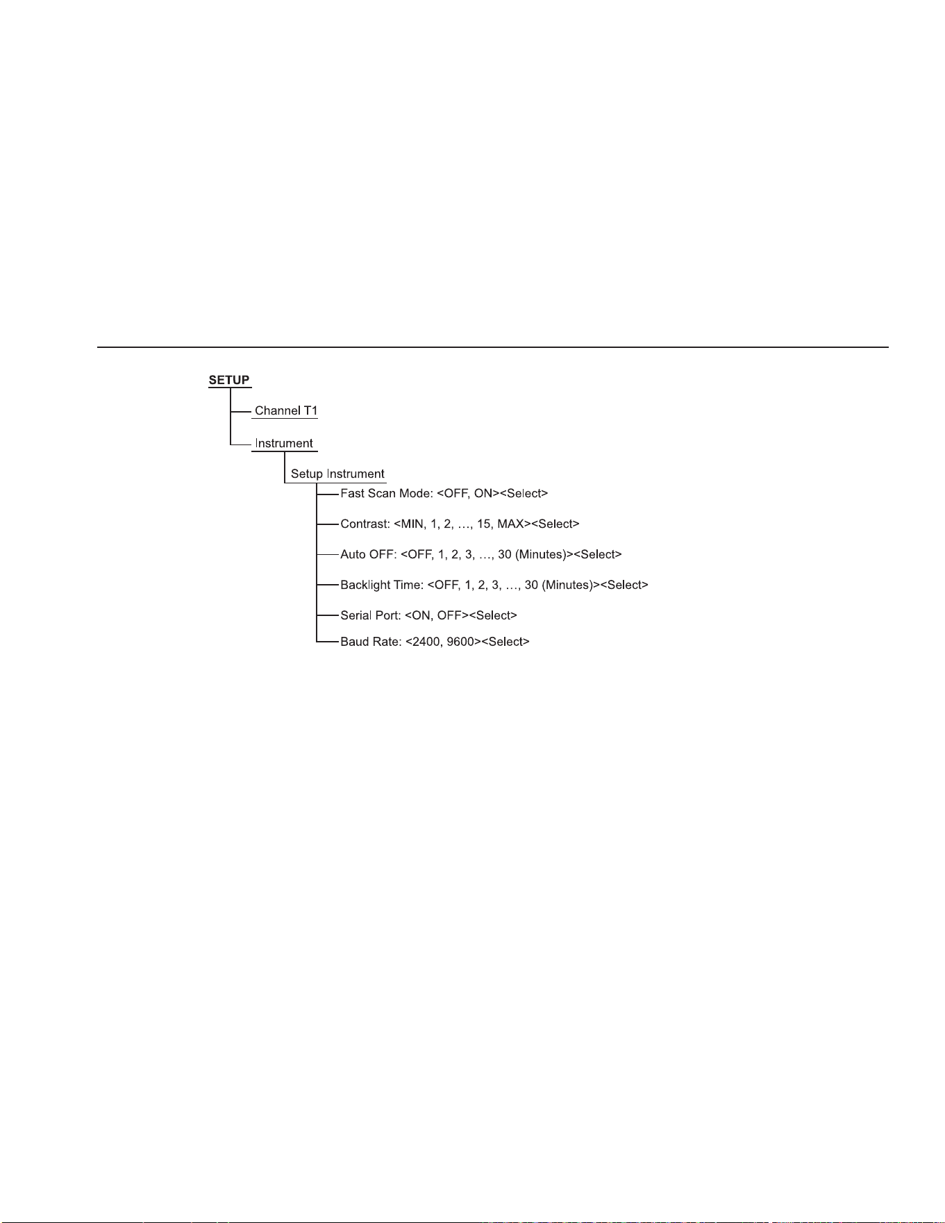
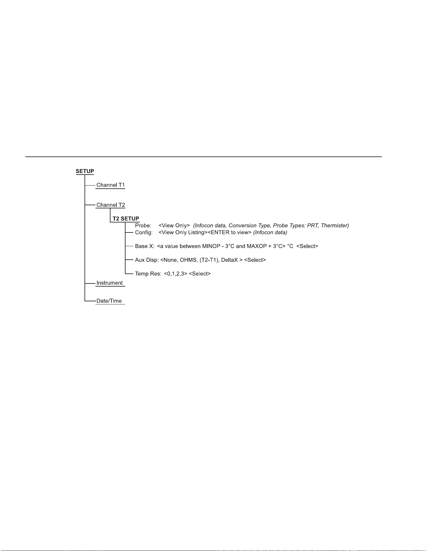
Figure 6 1523 Menu (cont)
1.888.610.7664 sales@GlobalTestSupply.com
Fluke-Direct.com
1523, 1524 Thermometer Readout
Setup
16
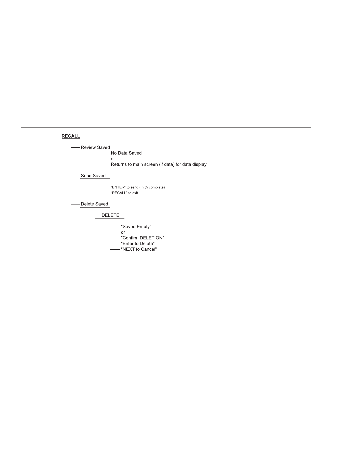
Figure 7 1523 Menu (cont)
1.888.610.7664 sales@GlobalTestSupply.com
Fluke-Direct.com
Quick Start
Setup
17
1524 Key FunctionsTable 5
No Key Description
1
Power on or off
2
Yellow Second or Special Function Key
3
Turns the backlight on or off
4
STATS
1st Press: Max, 2nd Press: Min, 3rd Press: Ave, 4th Press: STD DEV
5
°
C
°
F
Units, °C/°F
6
HOLD
1st press - Holds value on screen "-- HOLD --" across bottom of screen. 2nd press - Releases Screen hold.
7
SETUP
Enters setup menu, see menu structure
8
SAVE
Saves measurement as a logged data point
9
Arrows increment or decrement selections in an active field. In Graph Mode, Arrows change the scale of the
graph.
1.888.610.7664 sales@GlobalTestSupply.com
Fluke-Direct.com
1523, 1524 Thermometer Readout
Setup
18
No Key Description
10
ENTER
Selects highlighted selection, Saves a new selection.
11
RECALL
1st press - Enters Recall Menu, 2nd press - Exits Recall Menu
12
NEXT
Moves down to next option on screen.
13
+
STATS
“RESET” - Resets Stats Data
14
+
°
C
°
F
“Ω mV” - Toggles from °C to Ω or Ω to °C (PRT, thermistor), °C to mV or mV to °C (TC)
15
+
HOLD
“TREND” - Starts Graphing data
16
+
SAVE
“LOG” - Log a series of measurements, see Auto Log in menu structure
17
+
ENTER
“HOME” Returns user to main screen
1.888.610.7664 sales@GlobalTestSupply.com
Fluke-Direct.com
Quick Start
Setup
19
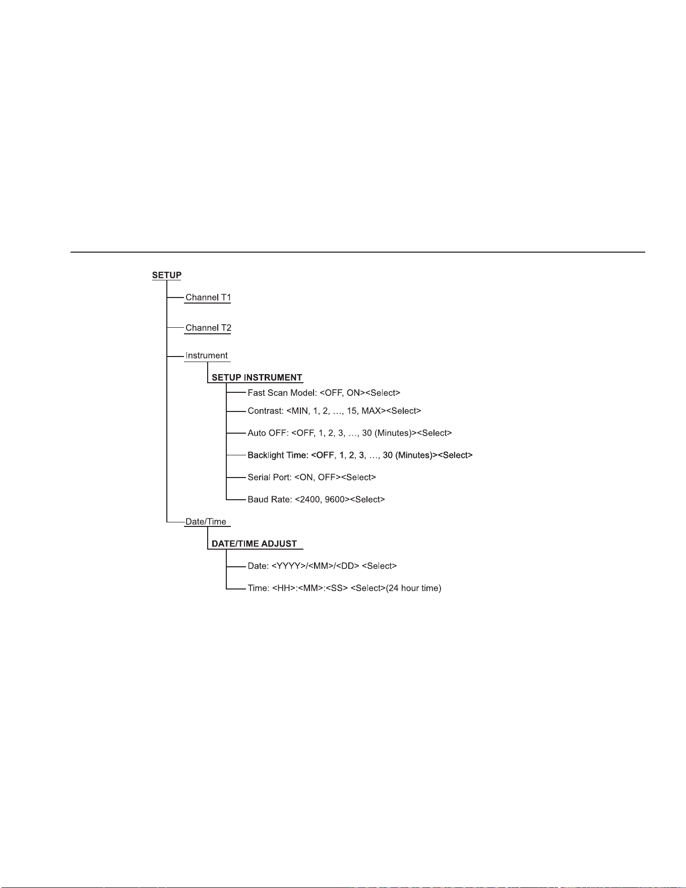
Figure 8 1524 Menu
1.888.610.7664 sales@GlobalTestSupply.com
Fluke-Direct.com
1523, 1524 Thermometer Readout
Setup
20
Figure 9 1524 Menu (cont)
1.888.610.7664 sales@GlobalTestSupply.com
Fluke-Direct.com
Quick Start
Setup
21
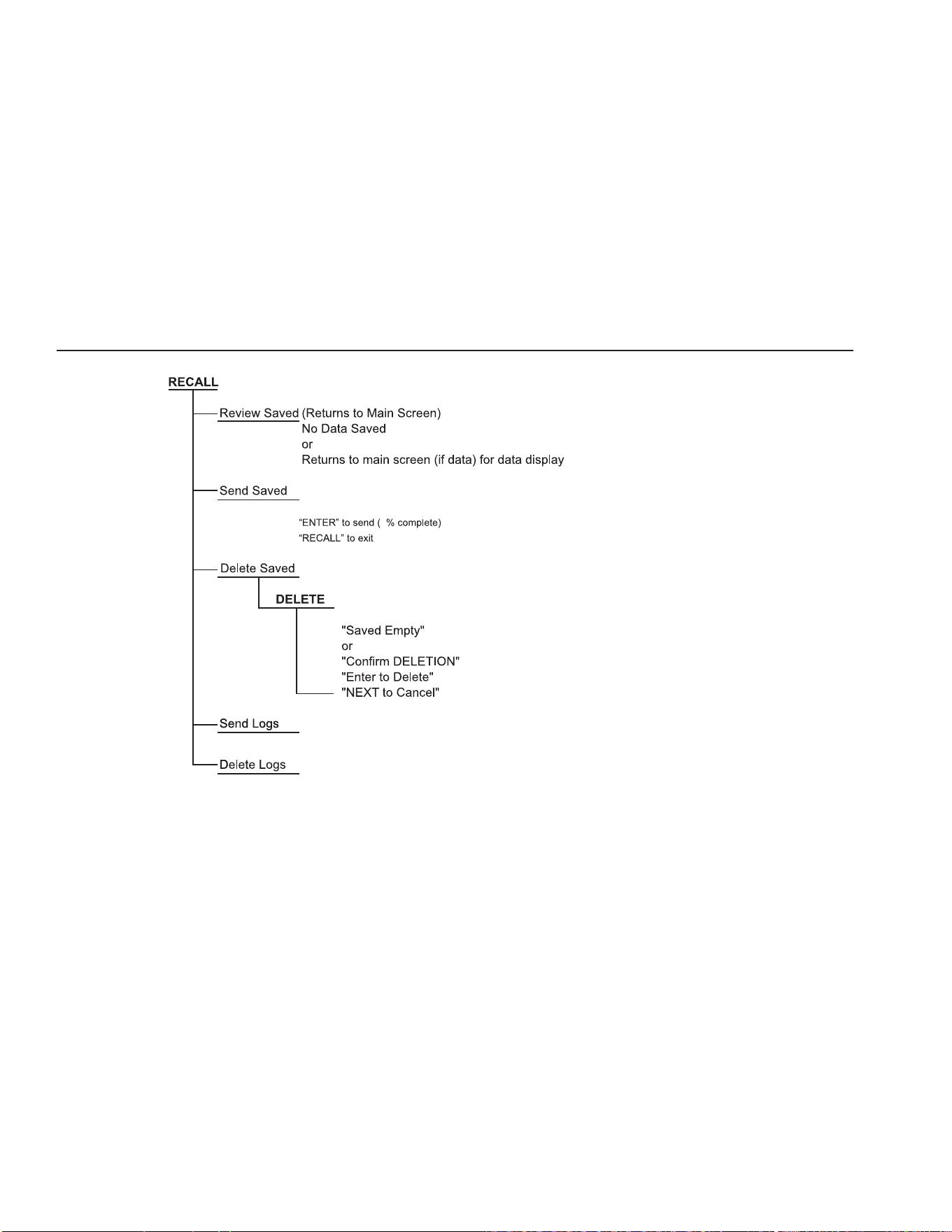
Figure 10 1524 Menu (cont)
1.888.610.7664 sales@GlobalTestSupply.com
Fluke-Direct.com
1523, 1524 Thermometer Readout
Setup
22
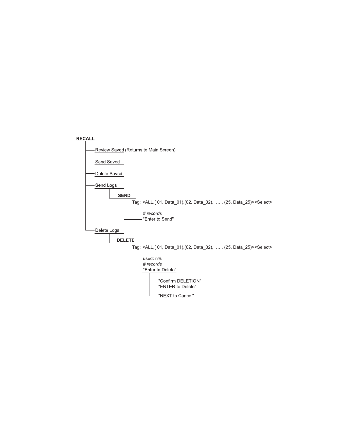
Figure 11 1524 Menu (cont)
1.888.610.7664 sales@GlobalTestSupply.com
Fluke-Direct.com
Quick Start
Setup
23
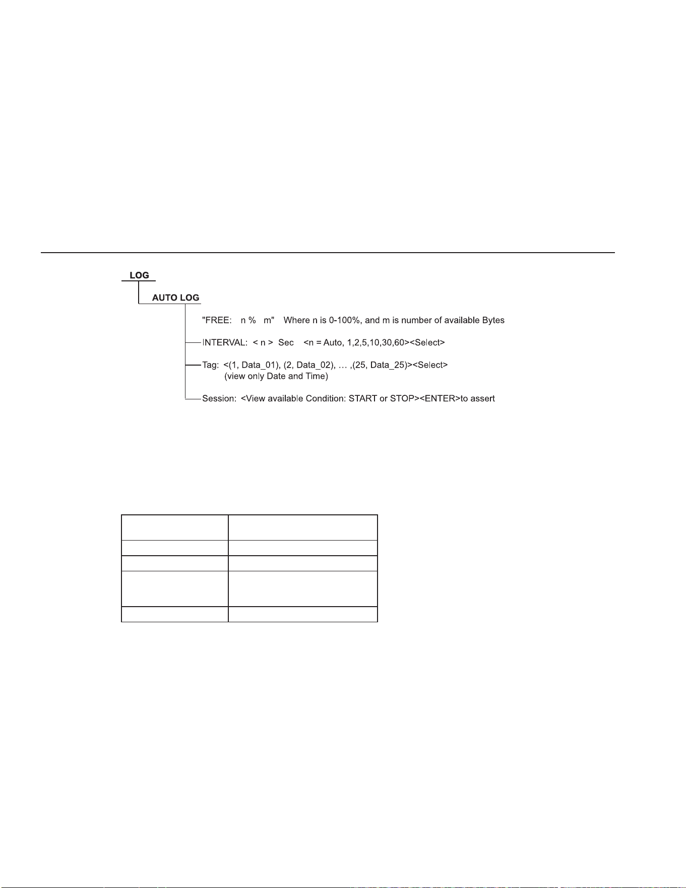
Figure 12 1524 Menu (cont)
1.888.610.7664 sales@GlobalTestSupply.com
Fluke-Direct.com
1523, 1524 Thermometer Readout
Specications
24
Figure 13 1524 Menu (cont)
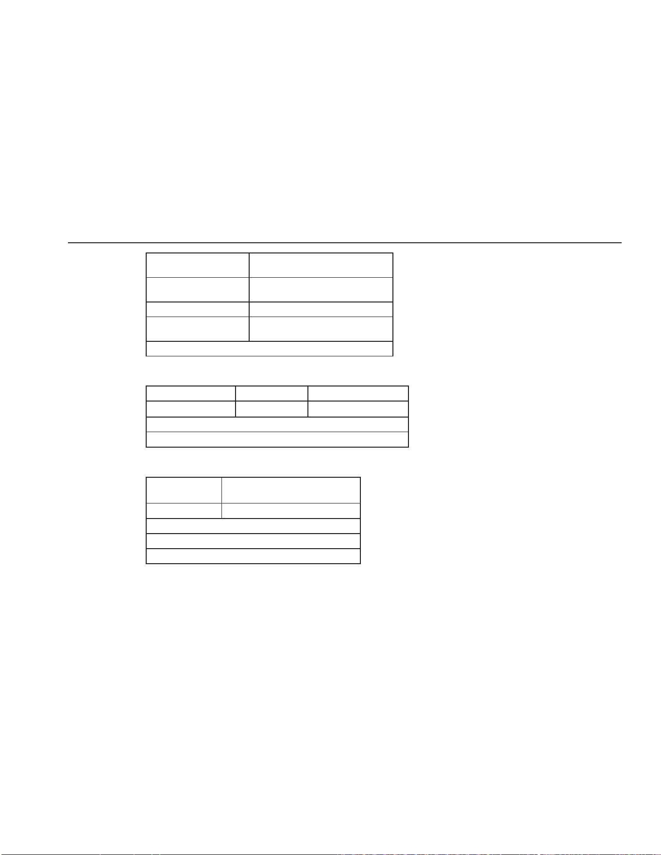
Specications2.2
Specications are based on a one year calibration cycle and apply from 13 °C to 33 °C unless stated
otherwise. All specications assume a ve minute warm up period.
General SpecificationsTable 6
Operating
Temperature
†
–10 °C to 60 °C
Storage Temperature –20 °C to 70 °C
Operating altitude 10,000 meters above mean sea level
Relative Humidity (%
RH operating without
condensation)
0 % to 90 % (non condensing)
Vibration Random, 2g, 5–500 Hz
1.888.610.7664 sales@GlobalTestSupply.com
Fluke-Direct.com
Quick Start
Specications
25
Power requirements 3 AA alkaline batteries
12 V dc universal power supply
Size 96 x 200 x 47 mm
(3.75 x 7.9 x 1.86 inches)
Weight 0.65 kg (1.4 lb)
Safety EN 61010-1:2001, CAN/CSA C22.2 No.
61010.1-04
†
Environmental conditions for all specifications: 13 °C to 33 °C
Millivolt MeasurementTable 7
Range Resolution Accuracy
–10 mV to 75 mV 0.001 mV
± (0.005 % + 5 µV)
Temperature Coefficient ( –10 °C to 13 °C, +33 °C to 60 °C):
± (0.001 %/°C + 1 µV/°C)
Ohms Measurement, RTDsTable 8
Ohms Range
Accuracy ± Ω
4 Wire
0 Ω to 400 Ω ± (0.004 % + 0.002 Ω)
Temperature Coefficient ( –10 °C to 13 °C, +33 °C to 60 °C):
0.0008 %/°C + 0.0004 Ω
Excitation Current: 1 mA
1.888.610.7664 sales@GlobalTestSupply.com
Fluke-Direct.com

1523, 1524 Thermometer Readout
Specications
26
Ohms Measurement, ThermistorTable 9
Ohms Range
Accuracy ± Ω, 4 Wire
200 Ω to 50 kΩ ± (0.01 % + 0.5 Ω)
50 kΩ to 500 kΩ
± (0.03 %)
Temperature Coefficient ( –10 °C to 13 °C , +33 °C to 60 °C):
0.002 %/°C + 0.1 Ω (0 Ω to 50 kΩ)
0.06 %/°C + 0.1 Ω (50 kΩ to 500 kΩ)
Excitation Current:
10 µA (0 Ω to 50 kΩ)
2 µA (50 kΩ to 500 kΩ)
Equivalent temperature accuracies derived from primary specications (Ω, mV)
Temperature, ThermocouplesTable 10
Type Range
Measure
Accuracies (ITS-90)
B 600 °C to 800 °C
800 °C to 1000 °C
1000 °C to 1800 °C
0.85 °C
0.68 °C
0.57 °C
C 100 °C to 550 °C
550 °C to 2300 °C
0.32 °C
0.71 °C
E –200 °C to 0 °C
0 °C to 950 °C
0.52 °C
0.22 °C
J –200 °C to 0 °C
0 °C to 1200 °C
0.52 °C
0.23 °C
K –200 °C to 0 °C
0 °C to 1370 °C
0.61 °C
0.24 °C
1.888.610.7664 sales@GlobalTestSupply.com
Fluke-Direct.com

Quick Start
Specications
27
Type Range
Measure
Accuracies (ITS-90)
L –200 °C to 0 °C
0 °C to 900 °C
0.36 °C
0.23 °C
M –20 °C to 0 °C
0 °C to 400 °C
400 °C to 1400 °C
0.26 °C
0.25 °C
0.22 °C
N –200 °C to 0 °C
0 °C to 1300 °C
0.72 °C
0.28 °C
R –20 °C to 0 °C
0 °C to 500 °C
500 °C to 1750 °C
1.09 °C
0.97 °C
0.49 °C
S –20 °C to 0 °C
0 °C to 500 °C
500 °C to 1750 °C
1.05 °C
0.95 °C
0.56 °C
T –200 °C to 0 °C
0 °C to 400 °C
0.60 °C
0.25 °C
U –200 °C to 0 °C
0 °C to 400 °C
0.54 °C
0.24 °C
Resolution: 0.01 °
Note 1: Accuracies are based on internal Reference
Junction Compensation. Refer to Technical manual for
equivalent external reference accuracies.
1.888.610.7664 sales@GlobalTestSupply.com
Fluke-Direct.com

1523, 1524 Thermometer Readout
Specications
28
Temperature, RTD Ranges, Table 11
and Accuracies (ITS-90)
Accuracy ± °C 4 Wire Probe
± 0.011 at –100 °C
± 0.015 at 0 °C
± 0.019 at 100 °C
± 0.023 at 200 °C
± 0.031 at 400 °C
± 0.039 at 600 °C
Resolution: 0.001°C (0.001°F)
Temperature, ThermistorTable 12
Accuracy ± °C
± 0.002 at 0 °C
± 0.003 at 25 °C
± 0.006 at 50 °C
± 0.014 at 75 °C
± 0.030 at 100 °C
Resolution: 0.001 °C (0.001 °F)
Based on a 10 kΩ (at 25 °C) thermister
with a beta value of 4000 Ω. See
technical manual for details.
1.888.610.7664 sales@GlobalTestSupply.com
Fluke-Direct.com