®
PN 2149032
September 2004 Rev. 3, 6/09
© 2004-2009 Fluke Corporation. All rights reserved. Printed in China.
Specifications are subject to change without notice.
All product names
are trademarks of their respective companies.
63/66/68
Infrared Thermometers
Users Manual
1.888.610.7664 sales@GlobalTestSupply.com
Fluke-Direct.com

LIMITED WARRANTY AND LIMITATION OF LIABILITY
This Fluke product will be free from defects in material and
workmanship for two years from the date of purchase. This
warranty does not cover fuses, disposable batteries, or
damage from accident, neglect, misuse, alteration, con-
tamination, or abnormal conditions of operation or handling.
Resellers are not authorized to extend any other warranty
on Fluke’s behalf. To obtain service during the warranty
period, contact your nearest Fluke authorized service cen-
ter to obtain return authorization information, then send the
product to that Service Center with a description of the
problem.
THIS WARRANTY IS YOUR ONLY REMEDY. NO OTHER
WARRANTIES, SUCH AS FITNESS FOR A PARTICULAR
PURPOSE, ARE EXPRESSED OR IMPLIED. FLUKE IS
NOT LIABLE FOR ANY SPECIAL, INDIRECT, INCIDEN-
TAL OR CONSEQUENTIAL DAMAGES OR LOSSES,
ARISING FROM ANY CAUSE OR THEORY. Since some
states or countries do not allow the exclusion or limitation of
an implied warranty or of incidental or consequential dam-
ages, this limitation of liability may not apply to you.
1.888.610.7664 sales@GlobalTestSupply.com
Fluke-Direct.com

i
Table of Contents
Title Page
Introduction....................................................... 1
Contacting Fluke .............................................. 1
Safety Information ............................................ 2
Symbols and Safety Markings........................ 3
Features ........................................................... 5
Display ............................................................. 7
Display (63).................................................... 8
Display (66/68)............................................... 8
Buttons (66/68)................................................. 9
How the Thermometers Work........................... 9
Operating the Thermometer ............................. 10
Temperature Measurement............................ 10
Locating a Hot or Cold Spot ........................... 10
Distance and Spot Size.................................. 11
Field of View .................................................. 13
Emissivity....................................................... 13
Switching °C and °F ....................................... 15
Trigger Lock (66/68)....................................... 15
Backlight and Laser On/Off Switch (63) ......... 16
Function Button Functions (66/68) ................. 16
Selecting a Function (66/68) .......................... 17
Setting the High Alarm, Low Alarm, and
Emissivity (66/68)........................................... 18
1.888.610.7664 sales@GlobalTestSupply.com
Fluke-Direct.com

63/66/68
Infrared Thermometers
ii
Using a Contact Temperature Probe (PRB)
(66/68) ........................................................... 18
HOLD ............................................................ 19
Storing Data (66/68) ...................................... 19
Recalling Data (66/68)................................... 19
LOG Clear Function....................................... 19
Maintenance .................................................... 20
Changing the Battery..................................... 20
Cleaning the Lens.......................................... 20
Cleaning the Housing .................................... 20
Troubleshooting ............................................... 21
Accessories...................................................... 21
CE Certification ................................................ 22
Specifications................................................... 22
1.888.610.7664 sales@GlobalTestSupply.com
Fluke-Direct.com

1
63/66/68
Introduction
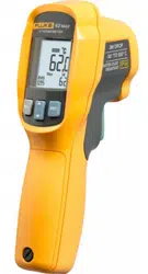
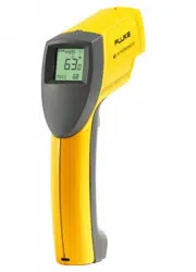
The Fluke Models 63, 66, and 68 Infrared Thermometers (“the
thermometers”) are for non-contact temperature measurement.
These thermometers determine an object’s surface temperature by
measuring the amount of infrared energy radiated by the object’s
surface. See Figure 2.
1.888.610.7664 sales@GlobalTestSupply.com
Fluke-Direct.com

63/66/68
Infrared Thermometers
2
Safety Information
XW Warning
A Warning identifies conditions and actions that pose
hazards to the user. To avoid electrical shock or personal
injury, follow these guidelines:
• * Do not point laser directly at eye or indirectly off
reflective surfaces.
• Before using the thermometer inspect the case. Do not
use the thermometer if it appears damaged. Look for
cracks or missing plastic.
• Replace the batteries as soon as the battery indicator
( ) appears.
• Do not use the thermometer if it operates abnormally.
Protection may be impaired. When in doubt, have the
thermometer serviced.
• Do not operate the thermometer around explosive gas,
vapor, or dust.
• Do not connect the optional external probe to live
electrical circuits.
• To avoid a burn hazard, remember that highly reflective
objects will result in lower than actual temperature
measurements.
• Do not use in a manner not specified by this manual or
the protection supplied by the equipment may be
impaired.
W Caution
To avoid damaging the thermometer or the equipment
under test protect them from the following:
• EMF (electro-magnetic fields) from arc welders,
induction heaters, etc.
• Static electricity
• Thermal shock (caused by large or abrupt ambient
temperature changes - allow 30 minutes for
thermometer to stabilize before use).
• Do not leave the thermometer on or near objects of
high temperature.
1.888.610.7664 sales@GlobalTestSupply.com
Fluke-Direct.com
63/66/68
Safety Information
3
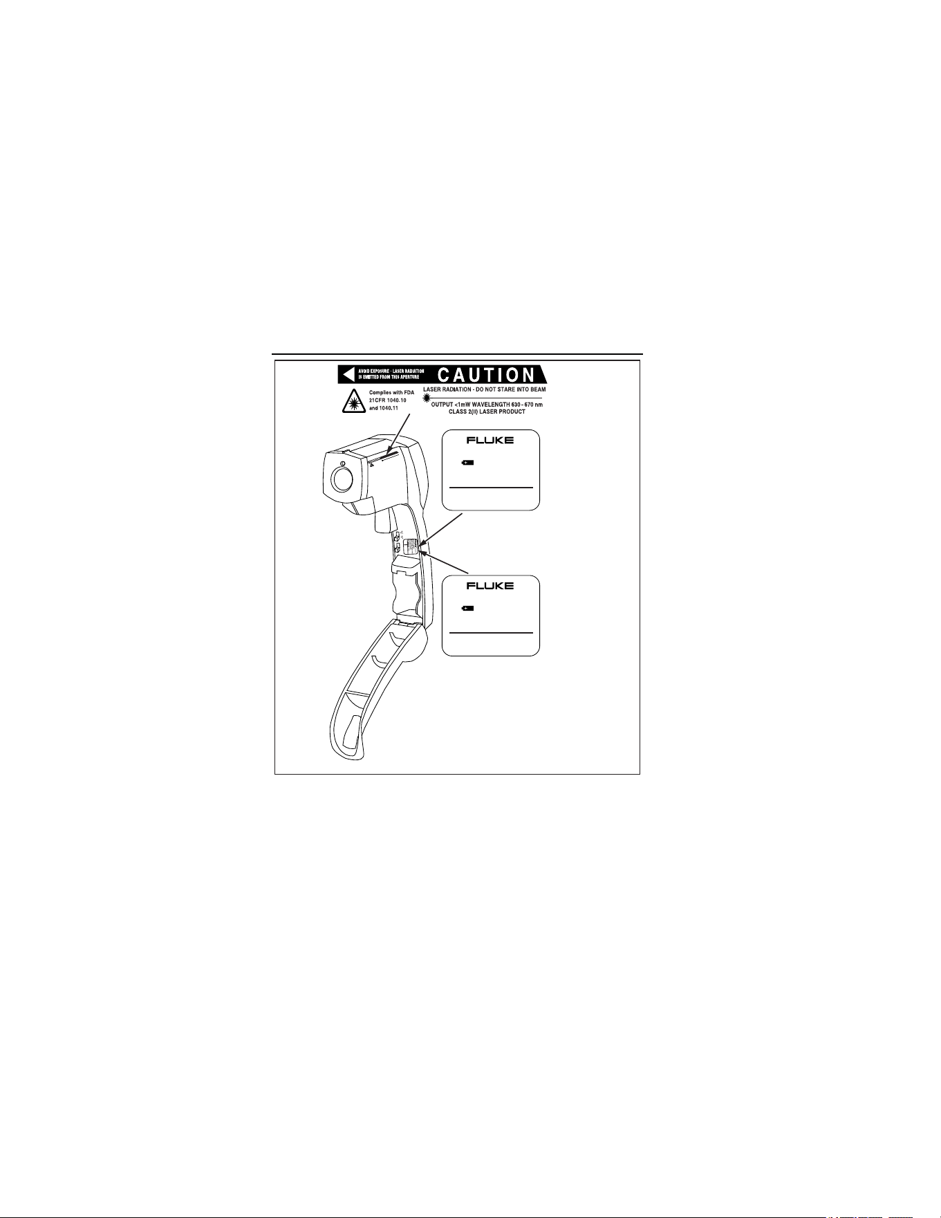
Symbols and Safety Markings
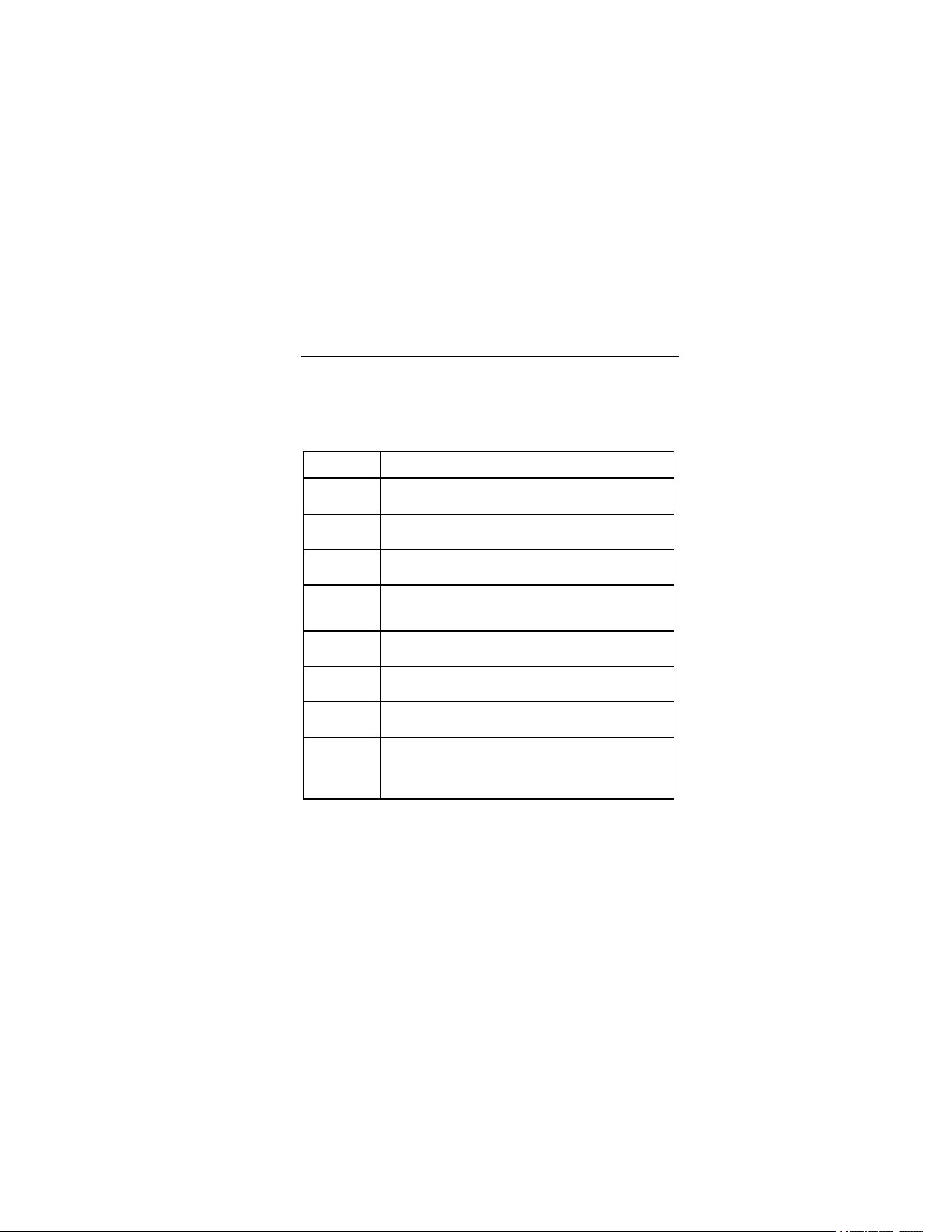
Table 1 and Figure 1 show various symbols and safety markings
that are on the thermometers and in this manual.
Table 1. Symbols
Symbol Explanation
W
Risk of danger. Important information. See Manual.
X
Hazardous voltage. Precedes warning
*
Warning. Laser.
P
Conforms to requirements of European Union and
European Free Trade Association (EFTA)
°C
Celsius
°F
Fahrenheit
M
Battery
~
Do not dispose of this product as unsorted
municipal waste. Go to Fluke’s website for recycling
information.
1.888.610.7664 sales@GlobalTestSupply.com
Fluke-Direct.com
63/66/68
Infrared Thermometers
4
CAUTION
LASER RADIATIO
N - D
O
NO
T STARE INTO
BEA
M
CLASS 2 (II) LASER PR
OD
UCT
O
UTPUT <1m
W
W
AVELENG
TH
630 - 670 nm
Com
plies with FDA
21C
FR 1040.10
and 1040.11
ON
OFF
63
66/68
MADE IN CHINA
MFG DATE: Dec 29, 2004
SERIAL #: 2421540101-0070
9V NEDA 1604
LASER / LIGHT
°C °F OFF ON
MADE IN CHINA
MFG DATE: Dec 29, 2004
SERIAL #: 2423260201-0030
9V NEDA 1604
LOCK
°C °F OFF ON
ame0010.eps
Figure 1. Safety Markings on the Thermometers
1.888.610.7664 sales@GlobalTestSupply.com
Fluke-Direct.com

63/66/68
Features
5
Features
The thermometers include:
• Single-spot laser sighting
• MAX temperature display
• Backlit display
• Durable, ergonomic construction
• Tripod mount
• Hard case and wrist strap
• MAX, MIN, DIF, AVG temperature displays (66/68)
• Adjustable emissivity (66/68)
• High and low alarm (66/68)
• Data logging (66/68)
• Trigger Lock (66/68)
• Contact probe jack (66/68)
1.888.610.7664 sales@GlobalTestSupply.com
Fluke-Direct.com
63/66/68
Infrared Thermometers
6
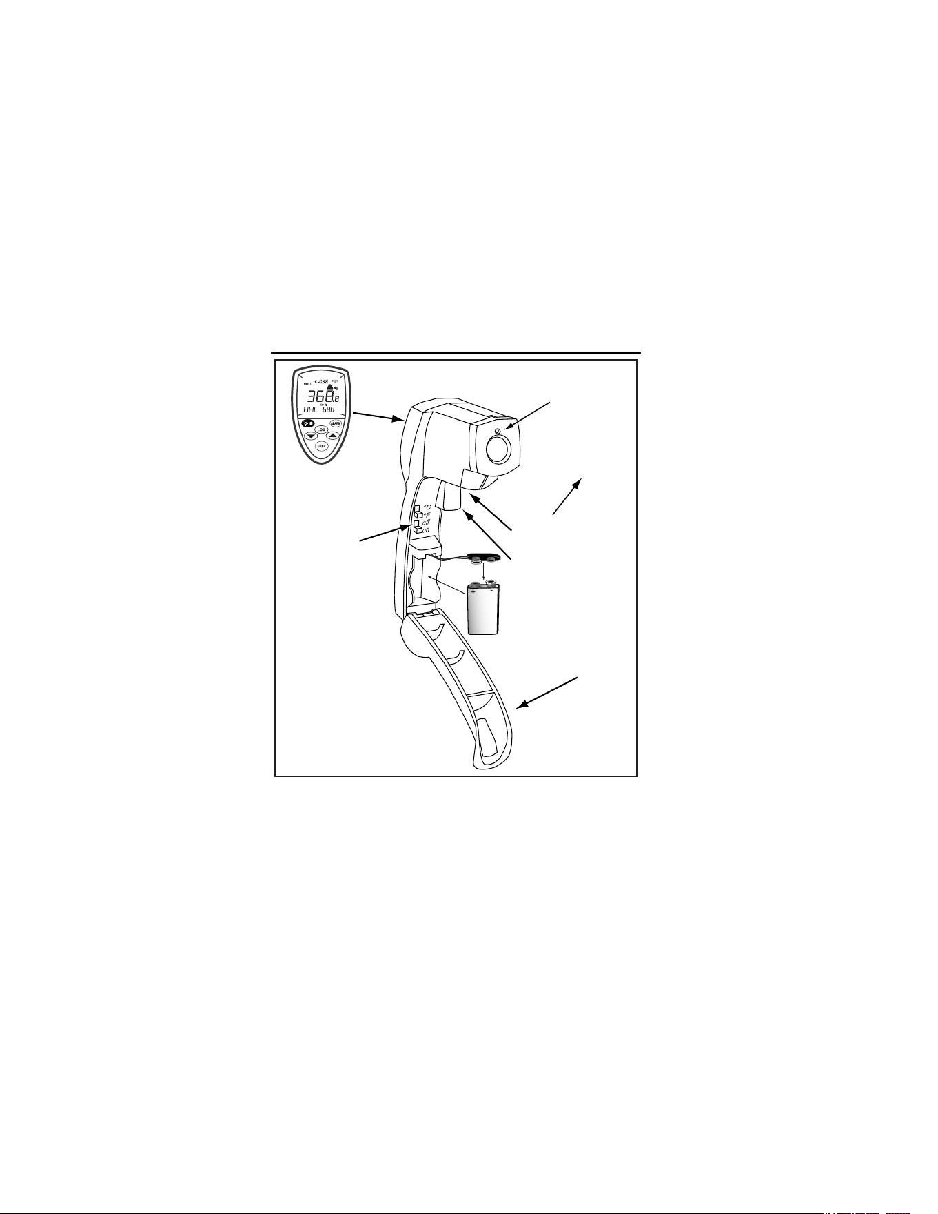
Display
(66/68 shown)
63: Backlight On/Off
66/68: Trigger
Lock On/Off
Battery Cover
Trigger
Battery Door
Release Button
Laser
ame007.eps
Figure 2. Infrared Thermometer
1.888.610.7664 sales@GlobalTestSupply.com
Fluke-Direct.com

63/66/68
Display
7
Display
A
B
C
D
E
F
G
H
I
J
ame001.eps
A
Backlight “On” symbol (63/66/68)
B
°C/°F symbol (Celsius/Fahrenheit) (63/66/68)
C
High alarm and low alarm symbol (66/68)
D
Maximum temperature display (63)
Temperature values for the MAX, MIN, DIF, AVG, HAL,
LAL, PRB (66/68)
E
Icon for MAX (63/66/68)
Icon for MIN, DIF, AVG, HAL, LAL, PRB (66/68)
F
LOG icon shows log mode for data storage (66/68)
G
Live temperature value (63/66/68)
H
SCAN or HOLD (63/66/68)
I
Emissivity symbol and value (63/66/68)
J
Low Battery and Laser “On” symbols (63/66/68)
Lock symbol (66/68)
1.888.610.7664 sales@GlobalTestSupply.com
Fluke-Direct.com

63/66/68
Infrared Thermometers
8
Display (63)
In the SCAN mode, the backlit reading displays both the live
temperature (G) and maximum temperature (D) in Celsius or
Fahrenheit (B). The thermometer holds the last reading for 7
seconds after the trigger is released and “HOLD” appears (H).
Display (66/68)
In SCAN mode, both the live temperature (G) and the selected
mode function (D,E) are displayed in Celsius or Fahrenheit (B).
The thermometer holds the last reading for 7 seconds after the
trigger is released and “HOLD” appears (H).
Notes
For all units, when the battery is low,
appears but the
thermometer will no longer function.
For the 66/68, to activate the laser and backlight, pull the
trigger. Press
once to activate the backlight, twice to
turn both laser and backlight on, and a third time to turn
them off.
1.888.610.7664 sales@GlobalTestSupply.com
Fluke-Direct.com
63/66/68
Buttons (66/68)
9
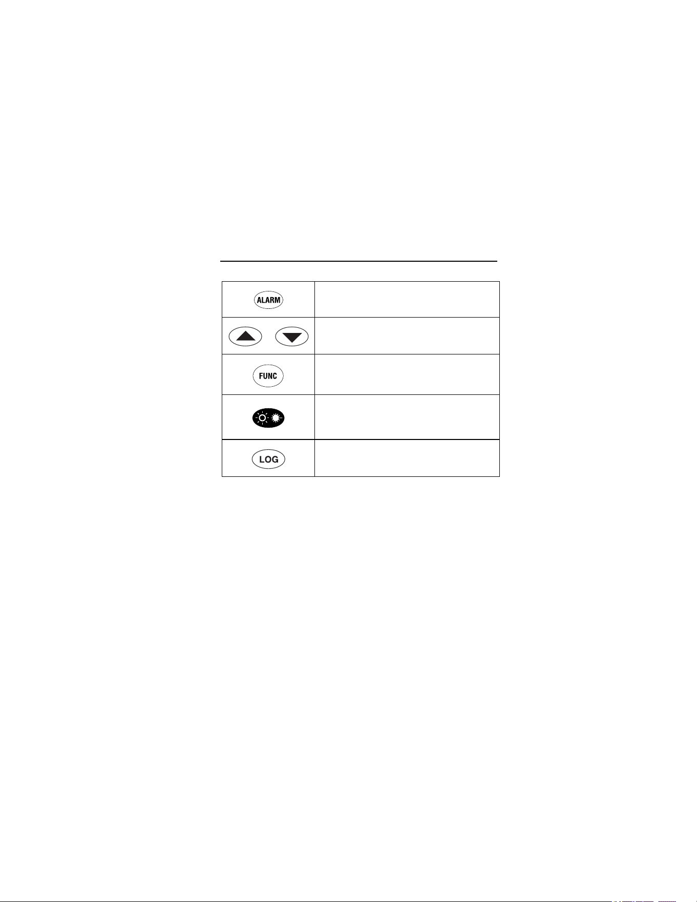
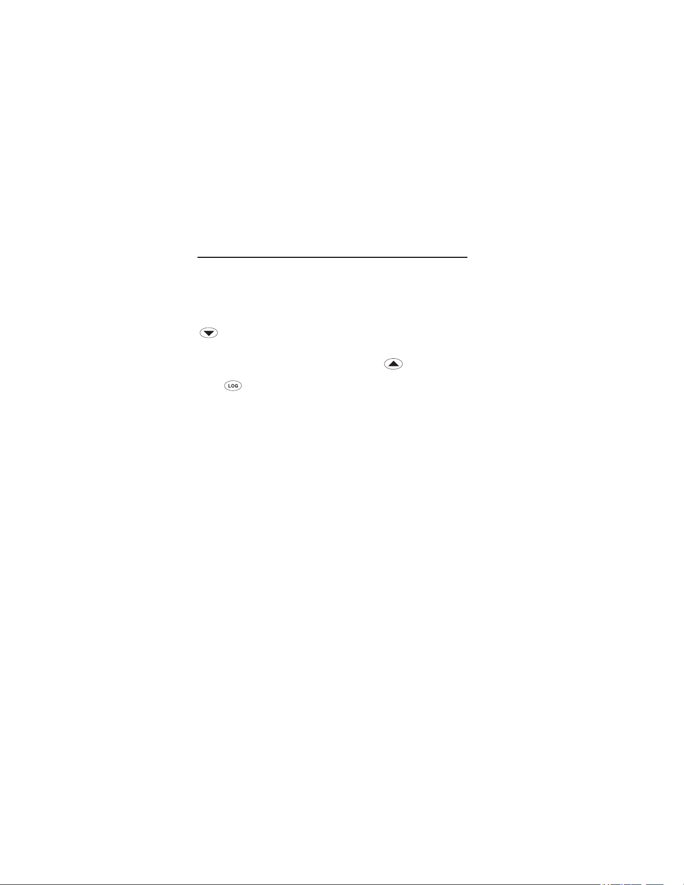
Buttons (66/68)
Sets high and low alarm
Up and down
Cycles through the function loop
Laser/Backlight on/off button (pull trigger
and press button to activate
laser/backlight)
LOG button (for storing data)
How the Thermometers Work
Infrared thermometers measure the surface temperature of an
opaque object. The thermometer’s optics sense emitted, reflected,
and transmitted energy, which is collected and focused onto a
detector. The unit’s electronics translate the information into a
temperature reading which the unit displays. The laser is used for
aiming purposes only. See Figure 3.
1.888.610.7664 sales@GlobalTestSupply.com
Fluke-Direct.com

63/66/68
Infrared Thermometers
10
Reflected energy
Emitted
Energy
Transmitted energy
Target
ame002.eps
Figure 3. How the Thermometer Works
Operating the Thermometer
Temperature Measurement
To measure temperature, point the unit at an object and pull the
trigger. Be sure to consider distance-to-spot size ratio and field of
view. The laser is used for aiming only.
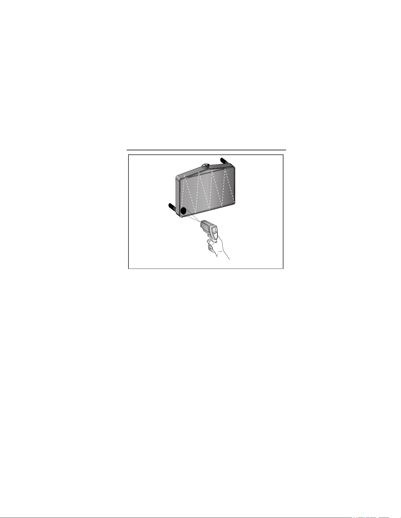
Locating a Hot or Cold Spot
To find a hot or cold spot, aim the thermometer outside the desired
area. Then, slowly scan across the area with an up and down
motion until you locate the hot or cold spot. See Figure 4.
1.888.610.7664 sales@GlobalTestSupply.com
Fluke-Direct.com
63/66/68
Operating the Thermometer
11
ame003.eps
Figure 4. Locating a Hot or Cold Spot
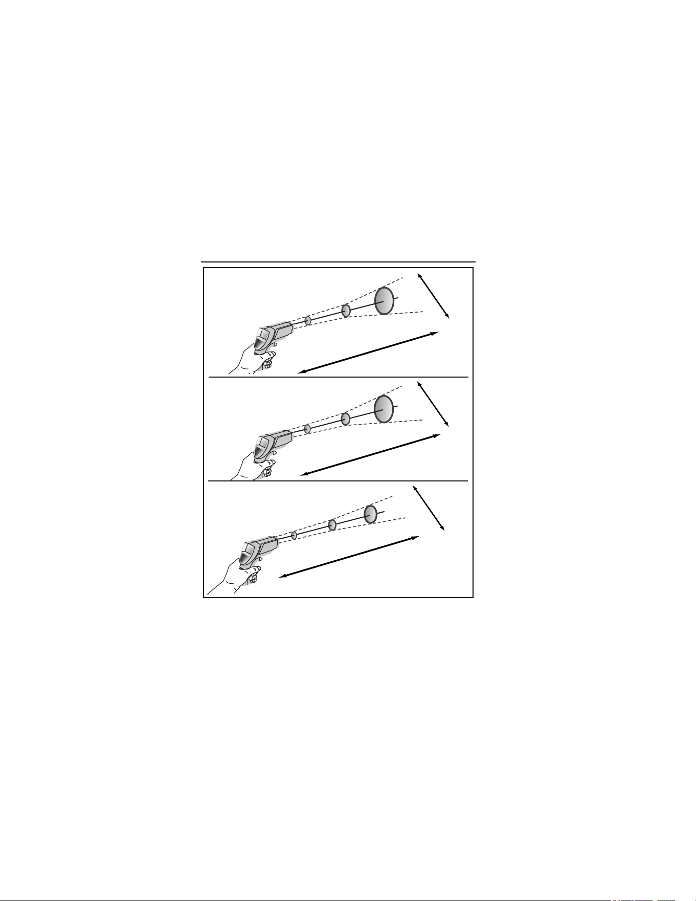
Distance and Spot Size
As the distance (D) from the object being measured increases, the
spot size (S) of the area measured by the unit becomes larger. The
relationship between distance and spot size for each unit is shown
in Figure 5. The focal point of each unit is 914 mm (36 in). The spot
sizes indicate 90 % encircled energy. See Figure 5.
1.888.610.7664 sales@GlobalTestSupply.com
Fluke-Direct.com
63/66/68
Infrared Thermometers
12
63
D:S=12:1
38 mm @
300 mm
75 mm @
900 mm
132 mm @
1500 mm
1.5 " @
12 "
3 " @
36 "
5.3 " @
60 "
S
D
66
D:S=30:1
24 mm @
300 mm
30 mm @
900 mm
62 mm @
1500 mm
0.9 " @
12 "
1.2 " @
36 "
2.5 " @
60 "
D
S
68
D:S=50:1
19 mm @
300 mm
18 mm @
900 mm
42 mm @
1500 mm
0.8 " @
12 "
0.7 " @
36 "
1.7 " @
60 "
D
S
ame005.eps
Figure 5. Distance and Spot Size
1.888.610.7664 sales@GlobalTestSupply.com
Fluke-Direct.com

63/66/68
Operating the Thermometer
13
Field of View
Make sure that the target is larger than the unit’s spot size. The
smaller the target, the closer you should be to it. See Figure 6.
ame004.eps
Figure 6. Field of View
Emissivity
Emissivity describes the energy-emitting characteristics of
materials. Most organic materials and painted or oxidized surfaces
have an emissivity of 0.95.
The 63 has a preset emissivity of 0.95. To compensate for
inaccurate readings that may result from measuring shiny metal
surfaces, cover the surface to be measured with masking tape or
flat black paint (<148 °C/300 °F). Allow time for the tape or paint to
1.888.610.7664 sales@GlobalTestSupply.com
Fluke-Direct.com
63/66/68
Infrared Thermometers
14
reach the same temperature as the surface beneath it. Measure
the temperature of the tape or painted surface.
The 66/68 thermometers allow you to adjust the unit’s emissivity for
the type of surface being measured. Refer to Table 2.
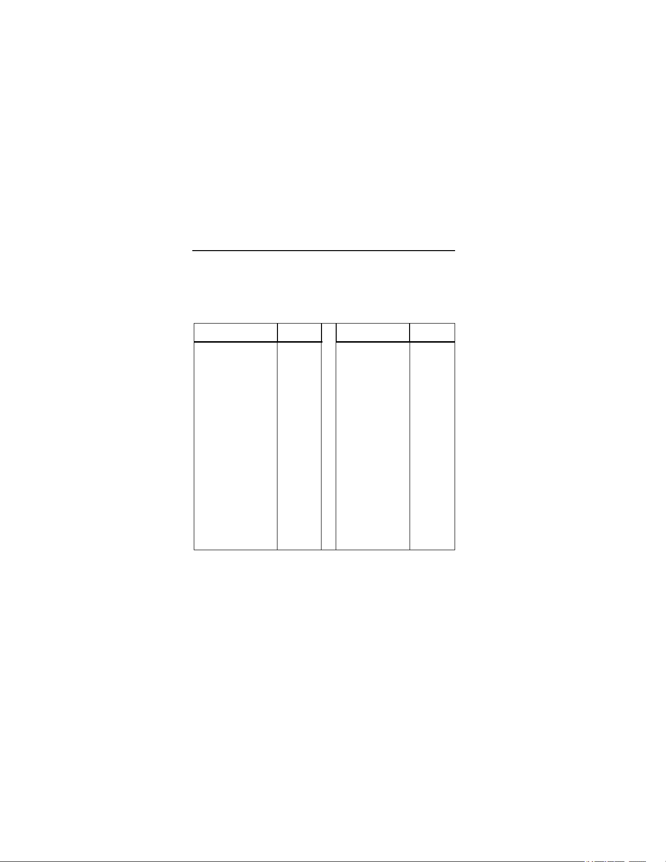
Table 2. Surface Emissivity
Measured Surface Emissivity Measured Surface Emissivity
METALS Iron
Aluminum
Oxidized 0.5-0.9
Oxidized 0.2-0.4 Rusted 0.5-0.7
Alloy A3003 Iron, Cast
Oxidized 0.3 Oxidized 0.6-0.95
Roughened 0.1-0.3 Unoxidized 0.2
Brass Molten 0.2-0.3
Burnished 0.3 Iron, Wrought
Oxidized 0.5 Dull 0.9
Copper Lead
Oxidized 0.4-0.8 Rough 0.4
Electrical Terminal
Blocks
0.6 Oxidized 0.2-0.6
Haynes Molybdenum
Alloy 0.3-0.8 Oxidized 0.2-0.6
Inconel Nickel
Oxidized 0.7-0.95 Oxidized 0.2-0.5
Sandblasted 0.3-0.6 Platinum
Electoropolished 0.15 Black 0.9
1.888.610.7664 sales@GlobalTestSupply.com
Fluke-Direct.com
63/66/68
Operating the Thermometer
15
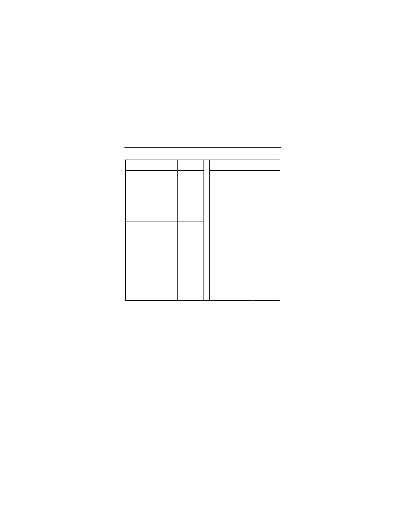
Table 2. Surface Emissivity (cont.)
Measured Surface Emissivity Measured Surface Emissivity
Steel Clay 0.95
Cold-Rolled 0.7-0.9
Concrete 0.95
Ground Sheet 0.4-0.6
Cloth 0.95
Polished Sheet 0.1
Glass
Zinc
Plate 0.85
Oxidized 0.1
Gravel 0.95
NON-METALS
Gypsum 0.8-0.95
Asbestos 0.95
Ice 0.98
Asphalt 0.95
Limestone 0.98
Basalt 0.7
Paper
(any color) 0.95
Carbon
Plastic
Unoxidized 0.8-0.9
Opaque 0.95
Graphite 0.7-0.8
Soil 0.9-0.98
Carborundum 0.9
Water 0.93
Ceramic 0.95
Wood (natural) 0.9-0.95
Switching
°
C and
°
F
Open the unit by pushing the button on the underside of the
thermometer near the trigger and pulling down and forward at the
top of the handle.
To toggle between °C and °F, slide the top switch to the
appropriate position. See Figure 2.
1.888.610.7664 sales@GlobalTestSupply.com
Fluke-Direct.com

63/66/68
Infrared Thermometers
16
Trigger Lock (66/68)
To lock the unit on for continuous measurement, slide the bottom
switch down. See Figure 2. If the trigger is pulled while the unit is
locked on, the laser and backlight will turn on if they have been
activated. When the unit is locked on, the laser will turn off when
the trigger is released. However, the backlight remains on unless it
is turned off using the keypad.
Backlight and Laser On/Off Switch (63)
To turn the backlight and laser on or off, slide the backlight and
laser switch to the appropriate position. See Figure 2.
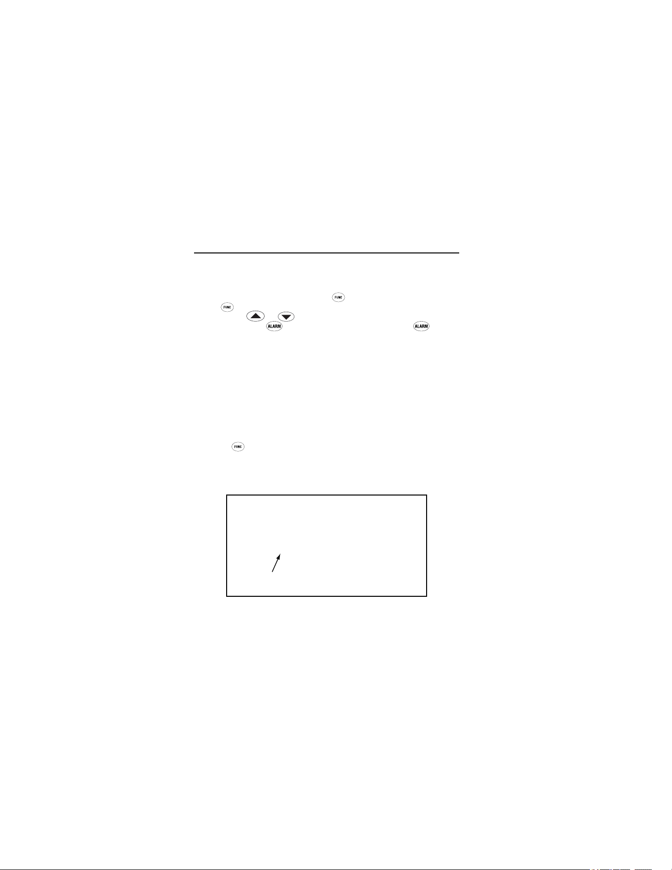
Function Button Functions (66/68)
Models 66 and 68 measure Maximum (MAX), Minimum (MIN),
Differential (DIF), and Average (AVG) temperatures each time a
reading is taken. DIF shows the difference between maximum and
minimum temperatures measured. AVG shows the average
temperature reading for each time the trigger is pulled or the unit is
locked on. This data is stored and can be recalled with
until a
new measurement is taken. See “Hold” for information on how to
recall stored data. When the trigger is pulled again, the unit will
being measuring in the last mode selected.
Pressing
also allows access to the High Alarm (HAL), Low
Alarm (LAL), Emissivity (EMS), Probe temperature (PRB-only
available when the probe is connected to the thermometer), and
Data logger (LOG). Each time
is pressed the unit advances the
function cycle. Figure 7 shows the sequence of functions in the
function cycle.
1.888.610.7664 sales@GlobalTestSupply.com
Fluke-Direct.com

63/66/68
Operating the Thermometer
17
ame006.eps
Figure 7. Function Cycle
Selecting a Function (66/68)
To select the MAX, MIN, DIF, or AVG mode, pull the trigger. While
holding the trigger, press
until the appropriate icon appears in
the lower left corner of the display. Each time
is pressed, the
thermometer advances through the function cycle. The function
cycle is shown in Figure 7.
1.888.610.7664 sales@GlobalTestSupply.com
Fluke-Direct.com
63/66/68
Infrared Thermometers
18
Setting the High Alarm, Low Alarm, and
Emissivity (66/68)
To set values for the High Alarm (HAL), Low Alarm (LAL), and
Emissivity, pull the trigger or press
to activate the display.
Press
until the appropriate icon appears in the lower left of the
display. Use
or to adjust the desired values. To activate
the alarms, press
. To deactivate the alarms, press
again.
Using a Contact Temperature Probe (PRB) (66/68)
XW Warning
To avoid electrical shock or personal injury, do not
connect the optional external probe to live electrical
circuits.
Connect the probe to the input on the side of the unit. PRB
appears in the left of the display. The probe temperature appears
in the lower right of the display. The live infrared temperature
continues to show in the center of the display. While the probe is
connected, you may still cycle through the mode functions by
pressing
. See Figure 8.
Note
PRB is only available in the Function loop when a probe
is connected to the unit. The probe temperature will not
activate the high alarm or low alarm.
Temperature
Probe
ame009.eps
Figure 8. Connecting a Temperature Probe
1.888.610.7664 sales@GlobalTestSupply.com
Fluke-Direct.com

63/66/68
Operating the Thermometer
19
HOLD
The unit’s display will remain activated for seven seconds after the
trigger is released, unless the unit is locked on (lock on 66/68
only). HOLD appears in the upper left of the display. During HOLD
or after the unit shuts off, recall stored values by pressing
without pulling the trigger (66/68). Each time
is pressed, the
unit advances through the function cycle. When the trigger is pulled
again, the unit will begin measuring in the last function selected.
Storing Data (66/68)
The thermometers are capable of storing up to 12 data locations.
The infrared temperature, temperature scale (°C or °F), and
emissivity are also stored.
To store data from an infrared reading, pull the trigger. While
holding the trigger, press
until LOG appears in the lower left of
the display. A log location number is shown below LOG. If no
temperature has been recorded in the shown LOG location, 3
dashes will appear in the lower right corner. Aim the unit at the
desired target and press
. A tone confirms that the location
temperature has been recorded. The recorded temperature
appears in the lower right corner of the display. To select another
log location, press
or .
Recalling Data (66/68)
Recall stored data after the unit shuts off by pressing until LOG
appears in the display’s lower left corner. A LOG location is shown
below LOG and the stored temperature for that location will be
shown in the display’s lower right corner. To move to another LOG
location, press
or .
LOG Clear Function
The LOG Clear function allows you to quickly clear all logged data
points. This function can only be used when the unit is in LOG
1.888.610.7664 sales@GlobalTestSupply.com
Fluke-Direct.com
63/66/68
Infrared Thermometers
20
mode. It can be used when the thermometer has any number of
log locations stored.
Note
Only use the LOG Clear function if you want to clear all
the LOG location data that is stored in the unit’s memory.
To use LOG Clear, while in LOG mode, pull the trigger then press
until the unit reaches LOG location “0”.
Note
This can only be done when the trigger is pulled. LOG
location “0” cannot be accessed by using
.
When LOG location “0” shows in the display’s lower left corner,
press
. Three tones sound and the LOG location automatically
changes to “1”, signifying that all data locations have been cleared.
Maintenance
Changing the Battery
To install or change the 9 V battery, open the unit and attach the
battery to the battery snaps with the positive side facing toward the
rear of the battery compartment. See Figure 2.
Cleaning the Lens
Blow off loose particles using clean compressed air. Carefully wipe
the surface with a moist cotton swab. The swab may be moistened
with water.
Cleaning the Housing
Use soap and water on a damp sponge or soft cloth.
WCaution
To avoid damaging the thermometers, do NOT
submerge them in water.
1.888.610.7664 sales@GlobalTestSupply.com
Fluke-Direct.com
63/66/68
Troubleshooting
21
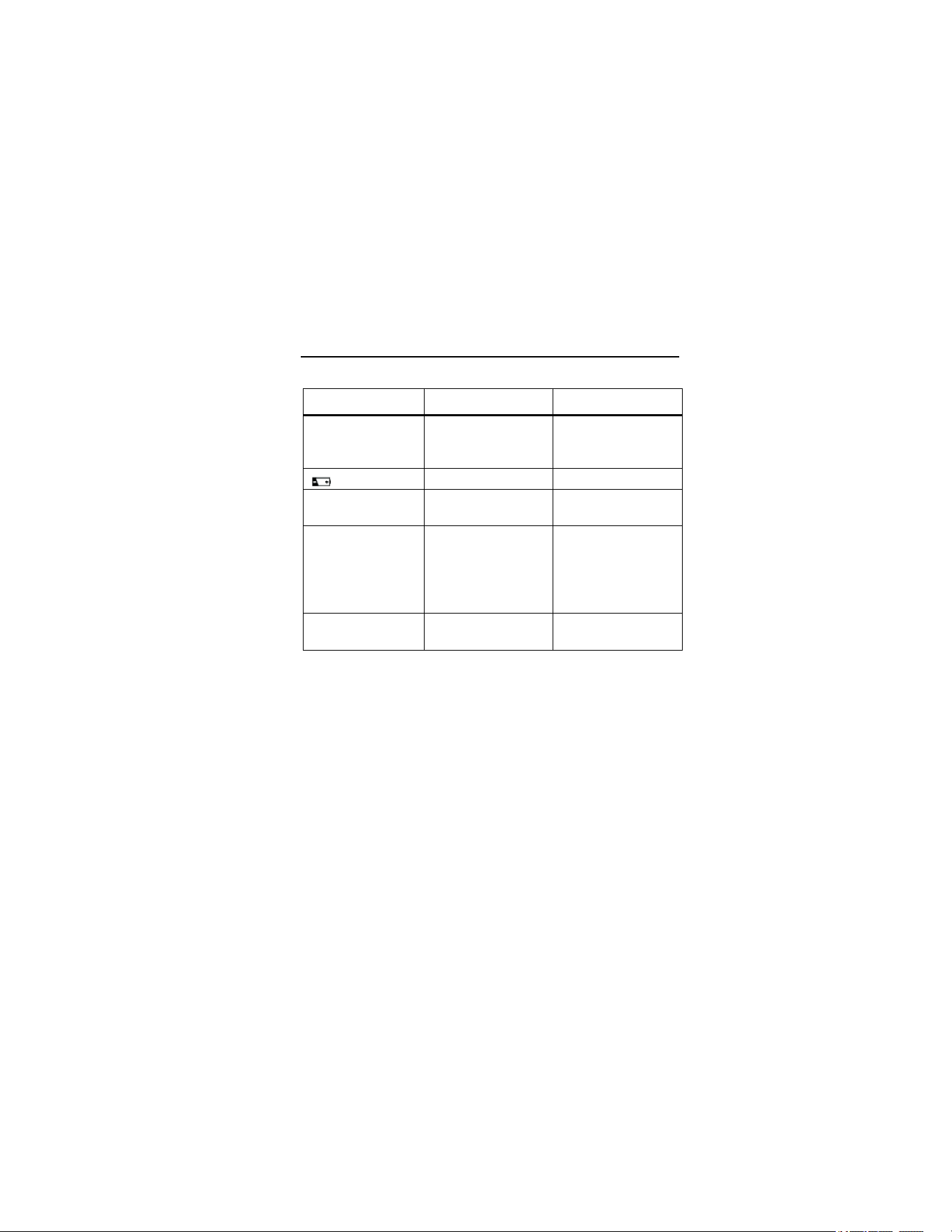
Troubleshooting
Symptom Problem Action
--- (on display) Target temperature
is over or under
range
Select target within
specifications
Low battery Replace battery
Blank display Possible dead
battery
Check and/or
replace battery
Laser does not
work
1. Low or dead
battery
2. Ambient
temperature above
40 °C (104 °F)
1. Replace battery
2. Use in area with
lower ambient
temperature
ERR Possible damage by
EMF
Contact your
distributor
Accessories
Optional accessories for the thermometers are:
• Contact probe (RTD) (66/68) - Fluke PN 2148313
• Nylon Soft Carrying Case – Fluke PN 2152040
• NIST/DKD certification
1.888.610.7664 sales@GlobalTestSupply.com
Fluke-Direct.com

63/66/68
Infrared Thermometers
22
CE Certification
The thermometers conform to the following standards:
• EN61326-1 EMC
• EN61010-1
• EN60825-1 Safety
Certification testing was conducted using a frequency range of 80-
1000 MHz with the instrument in three orientations.
Notes
63: Between 165 MHz and 880 MHz (
±
5%) at 3 V/m, the
instrument may not meet its stated accuracy.
66/68: Between 162 MHz and 792 MHz (
±
5%) at 3 V/m, the
instrument may not meet its stated accuracy.
Specifications
Temperature Range
Assumes ambient operating temperature of 23 °C (73 °F) to
25 °C (77 °F)
63: -32 °C to 535 °C (-25 °F to 999 °F)
66: -32 °C to 600 °C (-25 °F to 1100 °F)
68: -32 °C to 760 °C (-25 °F to 1400 °F)
Accuracy
Target Temperature:
Above 510 °C (63) ±1.5 % of reading
Above 510 °C (66/68) ±1 % of reading or ±1 °C (±2 °F),
whichever is greater
23 °C to 510 °C ±1% of reading or ±1 °C (±2 °F),
whichever is greater
-18 °C to 23 °C ±2 °C (±3 °F)
-26 °C to -18 °C ±2.5 °C (±4 °F)
-32 °C to -26 °C ±3 °C (±5 °F)
Resolution
63: 0.2 °C (0.5 °F)
66/68: 0.1 °C (0.1 °F)
1.888.610.7664 sales@GlobalTestSupply.com
Fluke-Direct.com

63/66/68
Specifications
23
Distance to Spot Ratio
63: 12:1
66: 30:1
68: 50:1
Emissivity
(Adjustment for surface measured)
63: Pre-set at 0.95
66/68: Digitally adjustable from 0.10 to 1.0
Response Time
500 mSec
Repeatability
±0.5 % of reading or ±1 °C (±2 °F), whichever is greater
Spectral Response
8 µm to 14 µm
Laser Sighting
Laser turns off above ambient temperature of 40 °C (104 °F)
Relative Humidity
10 % to 90 % RH non-condensing, at <30 °C (86 °F)
Tripod Mount
¼ in. 20 UNC threading
Operating Temperature
0 °C to 50 °C (32 °F to 120 °F)
Storage Temperature
-20 °C to 60 °C (-4 °F to 140 °F)
Weight
320 g (0.7 lbs)
Dimensions
200 mm x 160 mm x 55 mm (7.8 in x 6.30 in x 2.17 in)
Battery Type
9 V Alkaline or NiCd
Battery Life
63: 10 hours with laser and backlight on
40 hours with laser and backlight off
66/68: 20 hours with laser and backlight on
40 hours with laser and backlight off
1.888.610.7664 sales@GlobalTestSupply.com
Fluke-Direct.com

63/66/68
Infrared Thermometers
24
Optional Contact Probe (66/68)
Temperature Range -40 °C to 260 °C (-40 °F to 500 °F)
Accuracy
(Assumes ambient operating temperature of 23 °C (73 °F) to
25 °C (77 °F))
±1% of reading or ±1°C (±2°F), whichever is greater
Certifications: CE,
1.888.610.7664 sales@GlobalTestSupply.com
Fluke-Direct.com