
a
WARNING
To ensure the safety of operating personnel, and to avoid damage to this equipment:
DO NOT operate this unit without a properly grounded, properly polarized power cord.
DO NOT connect this unit to a non-grounded, non-polarized outlet.
DO USE a ground fault interrupt device.
WARNING
To ensure the safety of personnel, and to avoid damage to this equipment:
DO NOT use this unit in environments other than those listed in the user’s manual.
Follow all safety guidelines listed in the user’s manual.
WARNING
CALIBRATION EQUIPMENT SHOULD ONLY BE USED BY TRAINED PERSONNEL.
1.888.610.7664 sales@GlobalTestSupply.com
Fluke-Direct.com

Table of Contents
1 Introduction. . . . . . . . . . . . . . . . . . . . . . 1
2 Specifications and Environmental Conditions . . . 3
2.1 Specifications . . . . . . . . . . . . . . . . . . . . . . . 3
2.2 Environmental Conditions . . . . . . . . . . . . . . . . 4
2.3 Warranty . . . . . . . . . . . . . . . . . . . . . . . . . 4
3 Safety Guidelines . . . . . . . . . . . . . . . . . . 7
4 Quick Start . . . . . . . . . . . . . . . . . . . . . . 9
4.1 Unpacking . . . . . . . . . . . . . . . . . . . . . . . . 9
4.2 Power . . . . . . . . . . . . . . . . . . . . . . . . . . . 9
4.3 Connecting the Probe. . . . . . . . . . . . . . . . . . . 9
4.4 DC Power Option . . . . . . . . . . . . . . . . . . . . 10
5 Parts and Controls . . . . . . . . . . . . . . . . . 13
5.1 Front Panel Buttons . . . . . . . . . . . . . . . . . . . 13
5.2 Rear Panel . . . . . . . . . . . . . . . . . . . . . . . 14
6 General Operation . . . . . . . . . . . . . . . . . 15
6.1 Selecting Units . . . . . . . . . . . . . . . . . . . . . 15
6.2 Parameter Menus . . . . . . . . . . . . . . . . . . . . 15
6.3 Menu Lockout . . . . . . . . . . . . . . . . . . . . . . 15
6.4 Selecting the Probe Characterization . . . . . . . . . . 17
6.4.1 Setting the Probe Characterization Type . . . . . . . . . . . . 17
6.4.2 Setting the Characterization Coefficients . . . . . . . . . . . . 17
6.4.3 ITS-90 PRT and Coefficients . . . . . . . . . . . . . . . . . . 18
6.4.4 Callendar-Van Dusen (RTD) Conversion . . . . . . . . . . . . 20
6.4.5 IPTS-68 Conversion . . . . . . . . . . . . . . . . . . . . . . 20
6.4.5.1 Setting the Characterization Coefficients . . . . . . 21
6.4.5.2 Testing the Coefficients . . . . . . . . . . . . . . . 21
6.5 Filtering . . . . . . . . . . . . . . . . . . . . . . . . . 21
6.6 Setting the Current . . . . . . . . . . . . . . . . . . . 22
6.7 Power Saver. . . . . . . . . . . . . . . . . . . . . . . 22
7 Digital Communications Interface . . . . . . . . . 23
7.1 Serial Interface . . . . . . . . . . . . . . . . . . . . . 23
7.1.1 Setting the Baud Rate. . . . . . . . . . . . . . . . . . . . . . 24
7.1.2 Automatic Transmission of Measurements . . . . . . . . . . . 24
7.1.3 Time Stamp and System Clock . . . . . . . . . . . . . . . . . 24
7.1.4 Duplex Mode and Linefeed . . . . . . . . . . . . . . . . . . . 25
7.2 GPIB Interface. . . . . . . . . . . . . . . . . . . . . . 25
7.2.1 Setting the Address . . . . . . . . . . . . . . . . . . . . . . . 26
7.2.2 Setting the Termination Character . . . . . . . . . . . . . . . 26
7.2.3 Time Stamp . . . . . . . . . . . . . . . . . . . . . . . . . . . 26
i
1.888.610.7664 sales@GlobalTestSupply.com
Fluke-Direct.com

7.3 Remote Commands . . . . . . . . . . . . . . . . . . . 26
7.3.1 Measurement Commands . . . . . . . . . . . . . . . . . . . 26
7.3.1.1 Reading Temperature . . . . . . . . . . . . . . . . 28
7.3.1.2 Automatically Transmitting Measurements. . . . . . 29
7.3.1.3 Selecting the Unit of Measurement . . . . . . . . . 29
7.3.1.4 Enabling the Time Stamp . . . . . . . . . . . . . . 29
7.3.1.5 Setting the Clock . . . . . . . . . . . . . . . . . . . 29
7.3.2 Probe Characterization Commands. . . . . . . . . . . . . . . 29
7.3.2.1 Selecting the Characterization . . . . . . . . . . . . 29
7.3.2.2 Testing the Characterization . . . . . . . . . . . . . 30
7.3.3 Sample Commands . . . . . . . . . . . . . . . . . . . . . . . 30
7.3.3.1 Setting the Filter . . . . . . . . . . . . . . . . . . . 30
7.3.3.2 Setting the Probe Current . . . . . . . . . . . . . . 30
7.3.3.3 Setting the Power Saver . . . . . . . . . . . . . . . 31
7.3.4 Communication Commands . . . . . . . . . . . . . . . . . . 31
7.3.4.1 Setting the Duplex Mode . . . . . . . . . . . . . . . 31
7.3.4.2 Setting the Linefeed Option . . . . . . . . . . . . . 31
7.3.5 Calibration Commands . . . . . . . . . . . . . . . . . . . . . 31
7.3.5.1 Entering the Password . . . . . . . . . . . . . . . . 31
7.3.5.2 Setting the Menu Lockout . . . . . . . . . . . . . . 31
7.3.5.3 Setting the Calibration Coefficients . . . . . . . . . 32
7.3.5.4 Setting the Serial Number . . . . . . . . . . . . . . 32
7.3.6 Other Commands . . . . . . . . . . . . . . . . . . . . . . . . 32
7.3.6.1 Instrument Identification . . . . . . . . . . . . . . . 32
7.3.6.2 Reading a List of Commands . . . . . . . . . . . . 32
8 Calibration Procedure . . . . . . . . . . . . . . . 33
8.1 Accessing the Calibration Parameters . . . . . . . . . 33
8.2 Calibration Procedure . . . . . . . . . . . . . . . . . . 34
9 Maintenance . . . . . . . . . . . . . . . . . . . . 35
10 Troubleshooting . . . . . . . . . . . . . . . . . . 37
ii
1.888.610.7664 sales@GlobalTestSupply.com
Fluke-Direct.com

iii
Figures and Tables
Figure 1 Connecting a four-wire probe . . . . . . . . . . . . . . . . 10
Figure 2 12 V DC power source polarity . . . . . . . . . . . . . . . 11
Figure 3 1502A Front Panel . . . . . . . . . . . . . . . . . . . . . 13
Figure 4 1502A Back Panel . . . . . . . . . . . . . . . . . . . . . 14
Figure 5 Parameter Menu Structure . . . . . . . . . . . . . . . . . 16
Table 1 Matching Certificate Values to 1502A ITS-90 Coefficients . 18
Table 2 Setting Coefficients Rtpw, a5, and b5 . . . . . . . . . . . . 19
Table 3 Setting Coefficients Rtpw, a8, b8, a4, and b4 . . . . . . . . 19
Table 4 Setting Coefficients R(273.16), a6, b6, c6, and d . . . . . . 20
Figure 6 Serial Cable Wiring . . . . . . . . . . . . . . . . . . . . . 23
Table 5 Command List. . . . . . . . . . . . . . . . . . . . . . . . 27
Table 5 Command List Continued . . . . . . . . . . . . . . . . . . 28
1.888.610.7664 sales@GlobalTestSupply.com
Fluke-Direct.com

1 Introduction
The Hart Model 1502A is a low-cost high-accuracy digital thermometer readout
designed to be used with 25Ω and 100Ω RTDs and SPRTs. Its unique combi-
nation of features makes it suitable for a wide variety of applications from labo-
ratory measurement to industrial processes. Features of the 1502A include:
•
Measures 25Ω and 100Ω RTDs and SPRTs
•
Four-wire connection eliminates lead resistance effects
•
Accuracy: 0.006°C at 0°C
•
Resolution: 0.001°C
•
Fast one-second measurement cycle
•
Adjustable digital filter
•
Accepts ITS-90 characterization coefficients
•
Also accepts Callendar-Van Dusen and IPTS-68 coefficients
•
Adjustable excitation current
•
Displays temperature in Celsius, Fahrenheit, or Kelvin or displays resis-
tance in ohms
•
Password protection of critical parameters
• Large, bright eight-digit LED display
• Serial RS-232 interface standard; IEEE-488 GPIB interface optional
•
Detachable power cord
• Optional 12 V DC power
•
Light weight, small and portable
•
Sturdy, reliable construction
1502A Manual Rev. 952801 1
1 Introduction
1.888.610.7664 sales@GlobalTestSupply.com
Fluke-Direct.com

2 Specifications and Environmental
Conditions
2.1 Specifications
Specifications
Resistance Range
0Ω to 400Ω, auto-ranging
Resistance Accuracy, one
year
1
0Ω to 20Ω: 0.0005Ω
20Ω to 400Ω: 0.0025% (25 ppm) of reading
Resistance Accuracy, short
term
1, 2
0Ω to 30Ω: 0.0005Ω
30Ω to 400Ω: 0.0015% (15 ppm) of reading
Temperature Range
3
–200°C to 962°C (–328°F to 1764°F)
Temperature Accuracy
1, 3, 4
–100°C: 0.004°C
0°C: 0.006°C
100°C: 0.009°C
200°C: 0.012°C
300°C: 0.015°C
400°C: 0.018°C
500°C: 0.021°C
600°C: 0.024°C
Temperature Coefficient of
Resistance
1
1 ppm/°C
Resistance Resolution
0Ω to 20Ω: 0.0001Ω
20Ω to 400Ω: 0.001Ω
Temperature Resolution
0.001°C
Probe
Nominal R(0.01°C): 25Ω to 100Ω
RTD, PRT, or SPRT
Probe Connection
4-wire with shield, 5-pin DIN connector
Maximum acceptable lead re-
sistance
100Ω
Probe Characterizations
ITS-90 sub-ranges 4, 6, 7, 8, 9, 10, and 11
IPTS-68: R
0
, α, δ, a
4
, and c
4
Callendar-Van Dusen: R
0
, α, δ, and β
Probe Excitation Current
0.5 and 1 mA , reverses every 0.25 seconds
Measurement Period
1 second
Digital Filter
Exponential, 0 to 60 seconds time constant (user-selectable)
Communications
RS-232 serial standard
IEEE-488 (GPIB) optional, conforms to IEEE-488.1, capability
AH1, SH1, T6, L4, DC1
Display
8-digit, 7-segment, yellow-green LED; 0.5 inch high characters
Clock accuracy, typical
0.01%
Operating Temperature
Range
Full accuracy: 16°C to 30°C
Absolute: 0°C to 55°C
AC power
115 VAC ±10%, 50/60 Hz, 10 VA, nominal
230 VAC ±10%, 50/60 Hz, 10 VA (optional)
Detachable power cord
DC power (optional)
10 to 14 VDC, 1 A maximum
(220 mA typical, normal mode; 120 mA typical, power saver
mode)
Size
5.6 inches (14.3 cm) wide x 7.1 inches (18.1 cm) deep x 2.4
inches (6.1 cm) high
Weight
2.2 lb. (1.0 kg)
1502A Manual Rev. 952801 3
2 Specifications and Environmental Conditions
1.888.610.7664 sales@GlobalTestSupply.com
Fluke-Direct.com

1
Accuracy specifications apply within the recommended operating temperature range. Accuracy
limits are increased by a factor of the temperature coefficient outside this range.
2
Short-term accuracy includes nonlinearity and noise uncertainties. It does not include drift or cal
-
ibration uncertainties.
3
The temperature range may be limited by the sensor.
4
Temperature accuracy is for the 1502A only. It does not include probe uncertainty or probe char
-
acterization errors.
2.2 Environmental Conditions
Although the instrument has been designed for optimum durability and trou-
ble-free operation, it must be handled with care. The instrument should not be
operated in an excessively dusty or dirty environment. Maintenance and clean-
ing recommendations can be found in the Maintenance Section of this manual.
The instrument operates safely under the following conditions:
•
temperature range: Absolute 0–55°C (32–131°F); Recommended
16–30°C (61–86°F)
•
ambient relative humidity: 15–50%
•
pressure: 75kPa–106kPa
• mains voltage within ±10% of nominal
• vibrations in the calibration environment should be minimized
• altitude does not effect the performance or safety of the unit
4 Manual Rev. 952801 Hart Scientific
2 Specifications and Environmental Conditions
1.888.610.7664 sales@GlobalTestSupply.com
Fluke-Direct.com

3 Safety Guidelines
•
Operate the instrument in room temperatures between 16–30°C
(61–86°F) (recommended). Allow sufficient air circulation by leaving at
least 3 inches of space between the thermometer and nearby objects.
Note: Accuracy specifications apply within the recommended operating
temperature range. Accuracy limits are increased by a factor of the tem-
perature coefficient outside this range.
•
The thermometer is a precision instrument. Although it has been designed
for optimum durability and trouble free operation, it must be handled with
care. The instrument should not be operated in wet, oily, dusty, or dirty en-
vironments.
•
The instrument can measure extreme temperatures. Precautions must be
taken to prevent personal injury or damage to objects. Probes may be ex-
tremely hot or cold while connected to the thermometer and when re-
moved from the heat source. Cautiously handle probes to prevent
personal injury. Carefully place probes on a heat/cold resistant surface or
rack until they are at room temperature.
•
Use only a grounded AC mains supply of the appropriate voltage to power
the instrument. The thermometer requires less than 1 amp at 115 VAC
(±10%), 50/60 Hz and 230 VAC (±10%), 50/60 Hz.
•
Optional DC power of 10 to 14 V DC with 1 amp maximum.
• If a mains supply power fluctuation occurs, immediately turn off the instru-
ment. Power bumps from brown-outs and black-outs can possibly dam-
age the thermometer. Wait until the power has stabilized before
re-energizing the instrument.
1502A Manual Rev. 952801 7
3 Safety Guidelines
1.888.610.7664 sales@GlobalTestSupply.com
Fluke-Direct.com

4 Quick Start
4.1 Unpacking
Unpack the thermometer carefully and inspect it for any damage that may
have occurred during shipment. If there is shipping damage, notify the carrier
immediately.
Verify that the following components are present:
•
1502A Thermometer
•
Extra Probe Connector
•
Power Cord
•
Manual
•
Probe (optional—must be purchased separately)
•
Battery Pack (optional—must be purchased separately)
4.2 Power
Your 1502A is configured for either 115 VAC (±10%) operation or 230 VAC
(±10%) operation. Be careful to only connect the 1502A to a mains supply of
the correct voltage. Otherwise, the instrument may be damaged. The required
voltage is indicated on the back of the 1502A. The 1502A may draw up to 10
VA. The IEC type power cord connects to the back of the 1502A. The cord
must be plugged in to a grounded outlet. The power switch is located at the
back of the 1502A.
When the 1502A is powered on, wait briefly while it initializes. It will then begin
measuring and displaying temperature.
Because of the quality of the components used in the 1502A, it exhibits nearly
negligible drift as it warms up. The warm-up drift is typically less than 5 ppm.
Nevertheless, to ensure the best accuracy and stability, you may want to allow
the 1502A to warm up for ten minutes before use.
Accurate measurement requires that the probe be connected properly to the
input and the correct probe characterization set.
4.3 Connecting the Probe
The RTD or SPRT probe connects to the back of the 1502A using a five-pin
DIN plug. Figure 1 shows how a four-wire probe is wired to the five-pin DIN
connector. One pair of wires attaches to pins 1 and 2 and the other pair atta-
ches to pins 4 and 5. (Pins 1 and 5 source current and pins 2 and 4 sense the
potential.) If a shield wire is present it should be connected to pin 3.
A two-wire probe can also be used with the 1502A. It is connected by attach-
ing one wire to both pins 1 and 2 of the plug and the other wire to both pins 4
and 5. If a shield wire is present it should be connected to pin 3. Accuracy may
be significantly degraded using a two-wire connection because of lead resis
-
tance.
1502A Manual Rev. 952801 9
4 Quick Start
1.888.610.7664 sales@GlobalTestSupply.com
Fluke-Direct.com

4.4 DC Power Option
With the DC power option (Model 2502) installed the 1502A can be powered
from a 12 V battery or other 12 V DC power source. The DC power socket is
located on the rear panel of the 1502A above the AC power jack. The 1502A
accepts a 7/32 inch diameter, two-conductor DC power plug such as
Switchcraft® PN. 760. Observe the correct polarity as shown in Figure 2. The
outside conductor is positive and the inside is negative. The AC power switch
on the rear panel of the 1502A will not switch the DC power.
The optional Model 9313 Battery Pack, available from Hart Scientific, can be
used as a portable power source for the 1502A. It includes a 1.2 amp-hr 12V
sealed lead-acid battery, a DC power cord that plugs into the 1502A’s DC in-
put, a carrying bag, and a battery charger. The battery pack can provide four
to ten hours of operation with each charge depending on whether the power
saver feature is enabled (see Section 6.7).
10 Manual Rev. 952801 Hart Scientific
4 Quick Start
1
2
4
5
RTD Sensor
Probe Connector
3
Shield
Figure 1 Connecting a four-wire probe
1.888.610.7664 sales@GlobalTestSupply.com
Fluke-Direct.com

To recharge the battery, disconnect the battery’s plug from the 1502A and plug
it into the mating connector from the battery charger. Attach the charger’s AC
plug into an AC supply of the proper voltage (normally 100 to 125V AC, 50/60
Hz; optionally 200 to 230V AC, 50/60 Hz.). The charger takes about six hours
to fully charge the battery. The charger will stop charging automatically when
the battery is full.
Certain precautions must be observed with the battery and charger. These de-
vices can present safety concerns if misused or damaged. To avoid the risk of
electric shock or fire do not use the charger outdoors or in a dusty, dirty, or wet
environment. If the cord, case, or plug of the charger is damaged in any way
discontinue its use immediately and have it replaced. Never disassemble the
charger. The battery may contain chemicals that are hazardous. To avoid the
risk of exposure to dangerous substances or explosion, immediately discon-
tinue use of the battery if it leaks or becomes damaged. Never allow the bat-
tery to be shorted, heated, punctured, dropped, or squashed. Store the battery
where it will not come into contact with metal or fluids that might short circuit
the battery and where it will be safe from excessive temperatures. When no
longer usable the battery must be recycled. The battery may be returned to the
seller for recycling. Do not dispose the battery in a landfill. Never dispose the
battery in fire as there is danger of explosion which may cause injury or prop-
erty damage.
1502A Manual Rev. 952801 11
4 Quick Start
+
–
Figure 2 12 V DC power source polarity
1.888.610.7664 sales@GlobalTestSupply.com
Fluke-Direct.com
5 Parts and Controls
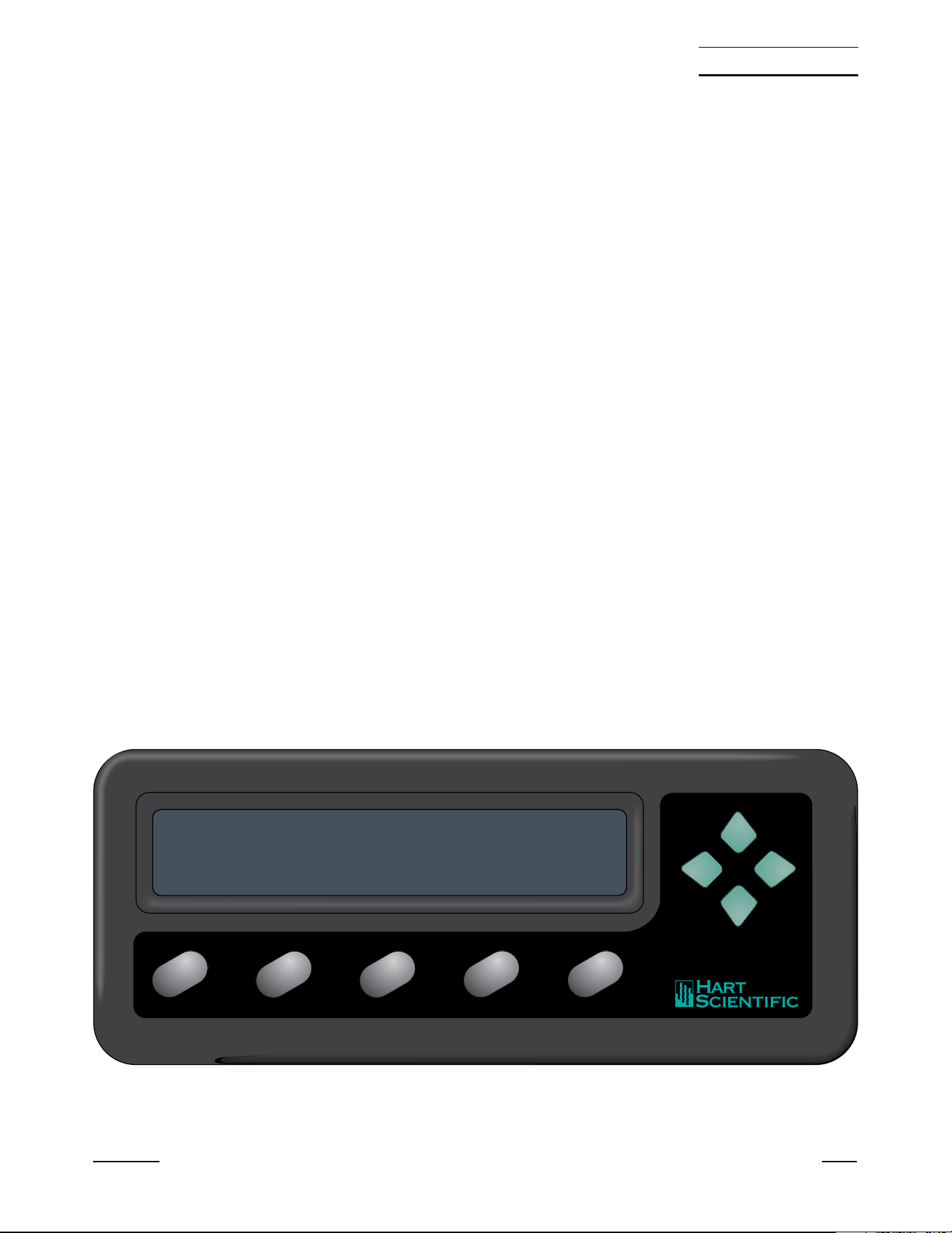
5.1 Front Panel Buttons
See Figure 3.
The front panel buttons are used to select units of measurement, access oper-
ating parameters, and alter operating parameters. The function of each button
is as follows:
C/Probe—This button selects units of degrees Celsius. In conjunction with the
Menu button, it selects the probe parameter menu.
F/Sample—This button selects units of degrees Fahrenheit. In conjunction
with the Menu button, it selects the sample parameter menu.
K/Comm—This button selects units of Kelvin. In conjunction with the Menu
button, it selects the communication parameter menu.
Ω/Exit (Cal)—This button selects resistance in ohms. While editing a parame-
ter, it cancels the immediate operation and skips to the next parameter. If the
Exit button is pressed for more than one-half second the menu is exited. In
conjunction with the Menu button, it selects the calibration parameter menu.
Menu/Enter—This button allows one of the unit/menu buttons to select a
menu. When editing a parameter, it accepts the new value and skips to the
next operation.
L and R —When editing a numeric parameter, these buttons move be-
tween digits. The selected digit flashes.
U and D— When editing a parameter, these buttons increase or decrease
the value of the parameter or a selected digit.
1502A Manual Rev. 952801 13
5 Parts and Controls
1502 A
C
Probe
F
Comm
K
Sample
Ω
Exit
Menu
Enter
84.981 C
Figure 3 1502A Front Panel
1.888.610.7664 sales@GlobalTestSupply.com
Fluke-Direct.com
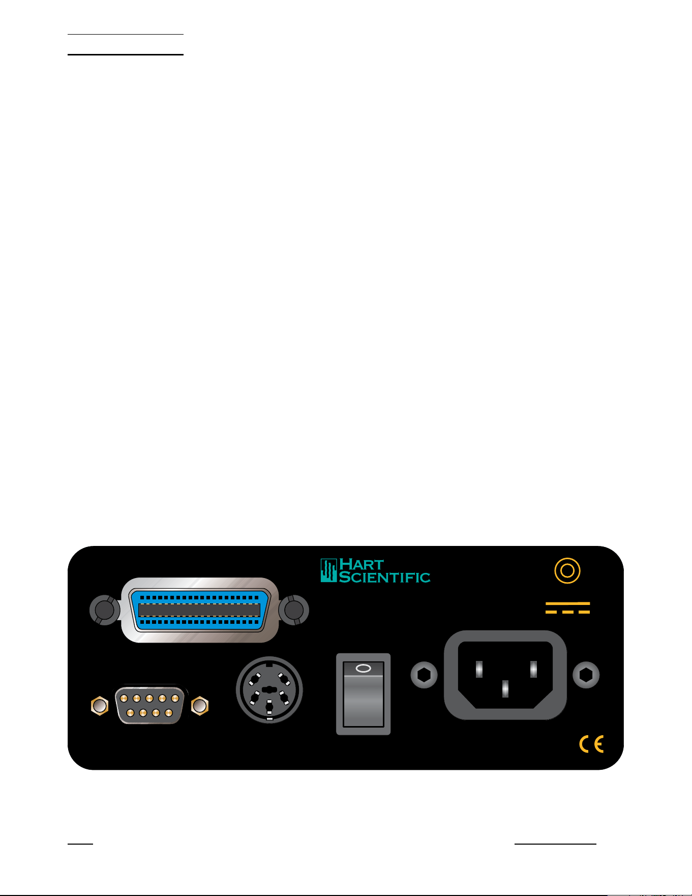
5.2 Rear Panel
See Figure 4.
Serial Port - The DB-9 connector is for interfacing the thermometer to a com-
puter or terminal with serial RS-232 communications.
Probe Connector - At the rear of the thermometer is the probe connector. The
probe must be connected for operation.
Power Switch - The power switch is located on the rear of the thermometer.
The AC power switch turns the unit on and off. It does not control the DC
power.
Power Cord - At the rear of the calibrator is the removable power cord that
plugs into a standard 115 VAC grounded socket. (230 VAC optional)
DC Power - The DC power, located on the rear of the thermometer, powers
the unit immediately when connected.
IEEE-488 Port (optional) - The GPIB connector is for interfacing the thermom-
eter to a computer or terminal with IEEE-488 communications.
14 Manual Rev. 952801 Hart Scientific
5 Parts and Controls
RS-232
IEEE-488
PROBE
POWER
Made in USA
AMERICAN FORK · UTAH 84003
12V 1.0A
–
+
l
0
Figure 4 1502A Back Panel
1.888.610.7664 sales@GlobalTestSupply.com
Fluke-Direct.com

6 General Operation
This section explains basic operation of the 1502A Thermometer.
6.1 Selecting Units
Temperature can be displayed in degrees Celsius (indicated with “C”), degrees
Fahrenheit (indicated with “F”), or Kelvin (indicated with “A” for absolute). The
resistance of the sensor can also be displayed (indicated with “o” for ohms).
Simply press the appropriate unit button, C, F, K, or Ω to select the units.
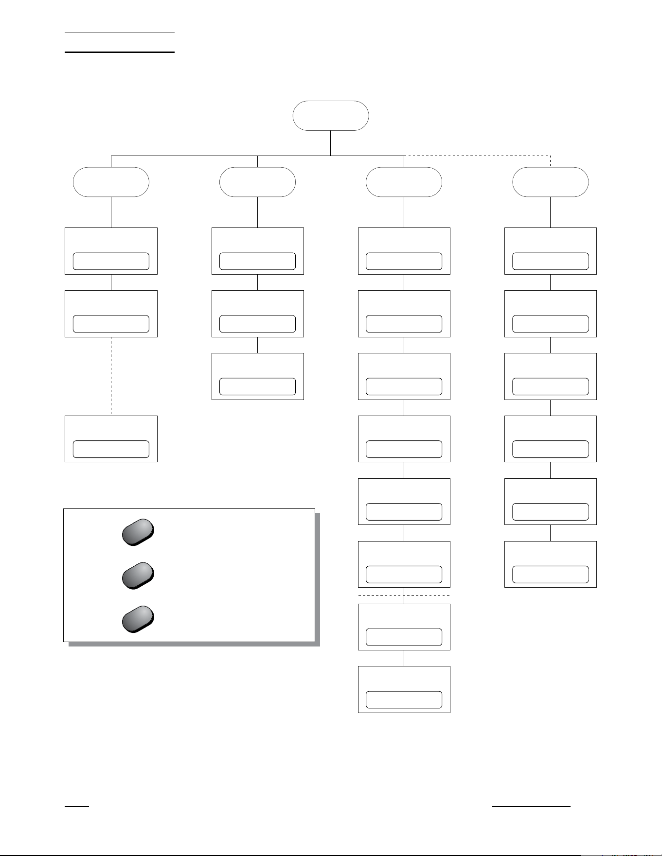
6.2 Parameter Menus
Except for unit selection, all functions and operating parameters are accessed
and edited within the parameter menus. There are four menus: the Probe pa-
rameter menu, Sample parameter menu, Comm (communication) parameter
menu, and Cal (calibration) parameter menu. The arrangement of parameters
in the menus is shown in Figure 5 on page 16.
Menus are selected by pressing the Menu/Enter button followed by the appro-
priate menu selection button. The name of the menu will briefly appear on the
display. For example, the Probe menu is selected by pressing the Menu/Enter
button (“SEt?” appears on the display) followed by the C/Probe button
(“ProbE” appears). Selecting the Cal menu requires that you press the
Menu/Enter button then press the Ω/Exit button and hold it down for at least
one second.
The Probe menu contains parameters for selecting the probe characterization
and setting the characterization coefficients. These parameters are explained
in Section 6.4. The Sample menu contains parameters for setting the filter and
excitation current. These are explained in Sections 6.5 and 6.6. The Comm
menu contains communication parameters such as the serial baud rate or
IEEE-488 address. These are explained in Sections 7.1 and 7.2. The Cal
menu contains the calibration parameters. These are explained in Section 8.1.
6.3 Menu Lockout
All menus can be locked out to prevent inadvertently changing parameters. By
default, only the Cal menu is locked out. The lockout option is accessed in the
Cal menu (see Section 8.1 “Accessing the Calibration Parameters”).
If menus are locked out you must enter the correct password (“2051”) to gain
access. After you select the menu (see the previous section) the display will
show “PA= 0000” and allow you to change the number to the correct pass-
word. Use the L and R buttons to move between the password digits and
the U and D buttons to increase or decrease the value of a digit. Press En-
ter when all the digits are correct. If the password is entered correctly the first
parameter in the menu will appear.
1502A Manual Rev. 952801 15
6 General Operation
1.888.610.7664 sales@GlobalTestSupply.com
Fluke-Direct.com
16 Manual Rev. 952801 Hart Scientific
6 General Operation
Menu
Sample Comm (Cal)Probe
Set clockSet filterSet probe type Enter password
Set time stampSet currentSet coefficients Set menu lockout
Set baud rateSet power saver Set CAL0
Set sample periodTest conversion Set CAL 100
Set duplex Set CAL 400
Set linefeed Factory reset
Set GPIB address
Set GPIB EOS
11.23.30FI= 4Pr= t90 PA= 0000
ts= OFFCur= 1.0 LO=CaL
2400 bPS= OFF -0.0006
00.00.01100.0000 +0.0128
duP=FULL -0.0011
LF= ON rESEt?
Add= 22
E= LF
Press after changing a parameter
Press briefly to skip a parameter
Hold to exit the menu
Enter
Exit
Exit
Figure 5 Parameter Menu Structure
1.888.610.7664 sales@GlobalTestSupply.com
Fluke-Direct.com

6.4 Selecting the Probe Characterization
Before the 1502A can measure temperature accurately it must know how to
calculate temperature from the resistance of the sensor. You must select a
conversion type and enter the proper characterization coefficients. There are
several temperature conversion algorithms available. The one to use depends
on the type of probe you are using and its calibration. The conversion algo-
rithms use coefficients that characterize the sensor. Coefficients are deter-
mined when the probe is calibrated. SPRTs and PRTs often use the ITS-90
algorithms and are provided with ITS-90 characterization coefficients.
6.4.1 Setting the Probe Characterization Type
The probe characterization type and characterization coefficients are set in the
Probe menu. Press the Menu button (“SEt?” appears), then the C/Probe but-
ton. The menu name, “ProbE”, will appear briefly then the characterization
type. The probe characterization types are indicated on the display as follows:
Pr= t90
ITS-90
Pr= rtd
Callendar-Van Dusen
Pr= t68
IPTS-68
Select the desired probe characterization type using the U and D buttons
and pressing the Enter button. After the characterization type is selected the
characterization coefficients follow. The coefficients that appear depend on the
probe type that was selected.
6.4.2 Setting the Characterization Coefficients
Probe characterization coefficients are set within the Probe menu after select-
ing the probe characterization type. Each coefficient appears with the name of
a coefficient shown briefly followed by its value. For example,
A4
+4.336079
For some coefficients, you only need to set the digits in the number. Other co-
efficients also have a sign as shown above (positive sign appears as “
+”). Use
the L and R buttons to move between the digits (and the sign). The se-
lected digit will flash. Use the U and D buttons to change a digit. Once the
sign and digits are correct, press Enter to accept the number. If you decide to
cancel any changes you have made, you may do so by pressing the Ω/Exit
button. This will immediately skip to the next coefficient.
If the coefficient also requires an exponent, it will appear after setting the num
-
ber as follows:
1502A Manual Rev. 952801 17
6 General Operation
1.888.610.7664 sales@GlobalTestSupply.com
Fluke-Direct.com

E -04
Increase or decrease the exponent using the U and D buttons. Once the ex
-
ponent is correct, press Enter to accept it.
6.4.3 ITS-90 PRT and Coefficients
The ITS-90 option is for PRTs calibrated and characterized using the
Interna-
tional Temperature Scale of 1990
equations. The parameters that appear
when ITS-90 is selected are “R0.01", ”A", “b”, “C”, “d”, “A4", and ”b4". These
should be set with the corresponding values that appear on the calibration cer-
tificate for the PRT. The parameter “R0.01" takes the triple point of water resis-
tance, often labeled ”Rtpw" or “R(273.16K)” on the certificate. Parameters “A”,
“b”, “C”, and “d” take the a
n
, b
n
,c
n
, and d coefficients where
n
is a number
from 5 to 11. Parameters “A4" and ”b4" take the a4 and b4 coefficients or the
a5 and b5 coefficients on the certificate.
Any ITS-90 parameter of the 1502A
that does not have a corresponding coefficient on the PRT’s certificate must
be set to 0.
The following table shows which parameter to set for each of the coefficients
that may appear on the certificate. The examples that follow demonstrate how
to set the ITS-90 parameters for certain cases. (Note: If the certificate has two
sets of coefficients, one set for “zero-power” calibration and one set for 1 mA
calibration, use the coefficients for the 1 mA calibration.)
18 Manual Rev. 952801 Hart Scientific
6 General Operation
1502A ITS-90 Coefficient Certificate Value
A a5, a6, a7, a8, a9, a10, or a11
b b5, b6, b7, b8, or b9
C c6 or c7
dd
A4 a4 or a5
b4 b4 or b5
Table 1 Matching Certificate Values to 1502A ITS-90 Coefficients
1.888.610.7664 sales@GlobalTestSupply.com
Fluke-Direct.com

Example 1:
A PRT was calibrated to ITS-90 and its calibration certificate states values for
coefficients Rtpw, a4, b4, a8, and b8. Set the 1502A parameters with values
from the certificate as follows.
Example 2:
A PRT was calibrated to ITS-90 and its calibration certificate states values for
coefficients Rtpw, a5 and b5. Set the 1502A parameters with values from the
certificate as follows:
1502A Manual Rev. 952801 19
6 General Operation
1502A Coefficient Certificate Value
R0.01 Rtpw
Aa5
bb5
C0
d0
A4 a5
b4 b5
Table 2 Setting Coefficients Rtpw, a5, and b5
1502A Coefficient Certificate Value
R0.01 Rtpw
Aa8
bb8
C0
d0
A4 a4
b4 b4
Table 3 Setting Coefficients Rtpw, a8, b8, a4, and b4
1.888.610.7664 sales@GlobalTestSupply.com
Fluke-Direct.com

Example 3:
A PRT was calibrated to ITS-90 and its calibration certificate states values for
coefficients R(273.16K), a6, b6, c6, and d. Set the 1502A parameters with val
-
ues from the certificate as follows:
6.4.4
Callendar-Van Dusen (RTD) Conversion
The RTD conversion uses the Callendar-Van Dusen equation:
[]
()
rt C
Rt
tt
t
Rt
°=
+− −
÷
≥
+
0
0
1
100 100
10
1
αδ
α
−−
÷
−−
÷
÷
δβ
tt t t
100 100
1
100
1
100
3
<
t
0
The coefficients
R
0
, α, β , and δ can be set by the user. They are indicated as
“r0”, “ALPHA”, “bEtA”, and “dELtA” on the display. For IEC-751 or DIN-43760
sensors, the coefficients for “r0”, “ALPHA”, “bEtA”, and “dELtA” should be
100.0, 0.00385, 1.507, and 0.111 respectively.
Some probes may be provided with A, B, and C coefficients for the
Callendar-Van Dusen equation in the following form:
[]
()
()
()
[]
rt C
RAtB
RAtBtCt t
t
t
°=
++
++ + −
≥
<
0
2
0
23
1
1 100
0
0
The A, B, and C coefficients can be converted to α, δ, and β coefficients using
the following formulas:
αδ β=+ =−
+
=−
+
AB
A
B
C
AB
100
100
100
1
10
100
8
6.4.5 IPTS-68 Conversion
The IPTS-68 characterization converts resistance to temperature according to
the International Practical Temperature Scale of 1968. The applicable coeffi
-
cients are
R
0
(“r0”), α (“ALPHA”), δ (“dELtA”), a
4
(“A4”), and c
4
(“C4”). You can
also select the temperature scale (“SCALE”) as IPTS-68 (“68”) or ITS-90
20 Manual Rev. 952801 Hart Scientific
6 General Operation
1502A Coefficient Certificate Value
R0.01 R(273.16K)
Aa6
Bb6
Cc6
Dd
A4 0.0
b4 0.0
Table 4 Setting Coefficients R(273.16), a6, b6, c6, and d
1.888.610.7664 sales@GlobalTestSupply.com
Fluke-Direct.com

(“90”). Selecting ITS-90 causes the temperature to be adjusted by a small
amount equal to the difference between the ITS-90 and IPTS-68 temperature
scales.
6.4.5.1 Setting the Characterization Coefficients
Probe characterization coefficients are set within the Probe menu after select-
ing the probe characterization type. Each coefficient appears with its name
shown briefly followed by its value. For example,
A4
+4.336079
For some coefficients, you only need to set the digits in the number. Other co-
efficients also have a sign as shown above (positive sign appears as “+”). Use
the L and R buttons to move between digits (and the sign). The selected
digit will flash. Use the U and D buttons to change a digit. Once the sign and
digits are correct, press Enter to accept the number. If you decide you would
like to cancel any changes you have made, you may do so by pressing the
Ω/Exit button. This will immediately skip to the next coefficient.
If the coefficient also requires an exponent, it will appear after setting the num-
ber as follows:
E -04
Increase or decrease the exponent using the p and q buttons. Once the expo-
nent is correct press Enter to accept it.
6.4.5.2 Testing the Coefficients
The 1502A provides a convenient method for testing the coefficients you have
entered to make sure they have been entered correctly. This is done by calcu-
lating temperature for given resistances and comparing the results with tem-
peratures listed on the probe’s calibration report. This conversion test function
is located at the end of the Probe menu. After setting the coefficients “tESt”
appears briefly followed by the resistance value. You can change the resis-
tance by using the U and D buttons to move between digits and the L and
R buttons to change a digit. After setting the resistance press Enter. The
1502A will calculate and display the temperature corresponding to the resis-
tance you entered. Compare this temperature with the temperatures listed on
the probe calibration report to verify that the coefficients you entered are cor-
rect.
6.5 Filtering
While measuring temperature, the readings may appear to vary. This may be
due to actual variations in temperature or electrical noise internal to the
1502A. The filter helps to smooth variations in the measurements and improve
resolution. The drawback is that filtering tends to slow the response to
changes in temperature. You can increase the filter time constant to further im
-
prove accuracy and resolution or decrease the time constant to reduce the re
-
1502A Manual Rev. 952801 21
6 General Operation
1.888.610.7664 sales@GlobalTestSupply.com
Fluke-Direct.com

sponse time. You can set it to any value between 0 and 60 seconds. A value
of 0 disables the filter. The default time constant is 4 seconds.
To change the filter value, enter the Sample menu. This is done by first press
-
ing the Menu button (“SEt?” appears) then pressing the F/Sample button.
The display will briefly indicate “SA Par”, then “FILtEr”, then the current filter
value. Use the U and D buttons to increase or decrease the filter value then
press Enter. The next parameter in the menu, the current, will then appear.
6.6 Setting the Current
You can select one of two options for the probe excitation current: 1.0 mA (de-
fault) or 0.5 mA. The current is set within the Sample menu. Press the Menu
button (“SEt?” appears) then press the F/Sample button. The filter value will
appear. Press Enter to continue. The display will briefly show “CurrEnt” fol-
lowed by the value for the current. You can use the Uand Dbuttons to change
the value for the current. Press Enter to continue.
6.7 Power Saver
The power saver feature is useful for conserving power when operating from a
battery. It causes the display to blank after a period of no user activity. The
power saver feature can reduce operating current by as much as 100 mA.
While the display is blanked a small illuminated dot appears on the left side of
the display as an indication that the 1502A is still operating. Pressing any but-
ton on the front panel restores the display. You can program the power saver
to activate after a specified period of time from 5 minutes to 60 minutes in in-
tervals of 5 minutes. You can also disable the power saver feature completely.
The power saver is off by default.
The power saver is programmed in the Sample menu. Press the Menu button
(“SEt?” appears) then press the Sample menu button. Press Exit twice to
skip to the power saver parameter. The display will briefly show “PO SA” fol-
lowed by the power saver setting. You can use the U and D buttons to
change the power saver period (in minutes) or set it to OFF. Press Enter to
continue.
22 Manual Rev. 952801 Hart Scientific
6 General Operation
1.888.610.7664 sales@GlobalTestSupply.com
Fluke-Direct.com
7 Digital Communications Interface
Remote communications allows an external device, such as a computer, to
communicate with the 1502A to obtain measurement data and control its oper-
ation. Communication is accomplished with various commands issued to the
1502A through the RS-232 port or optional IEEE-488 port. A full list of com-
mands is given in Section 7.3.
7.1 Serial Interface
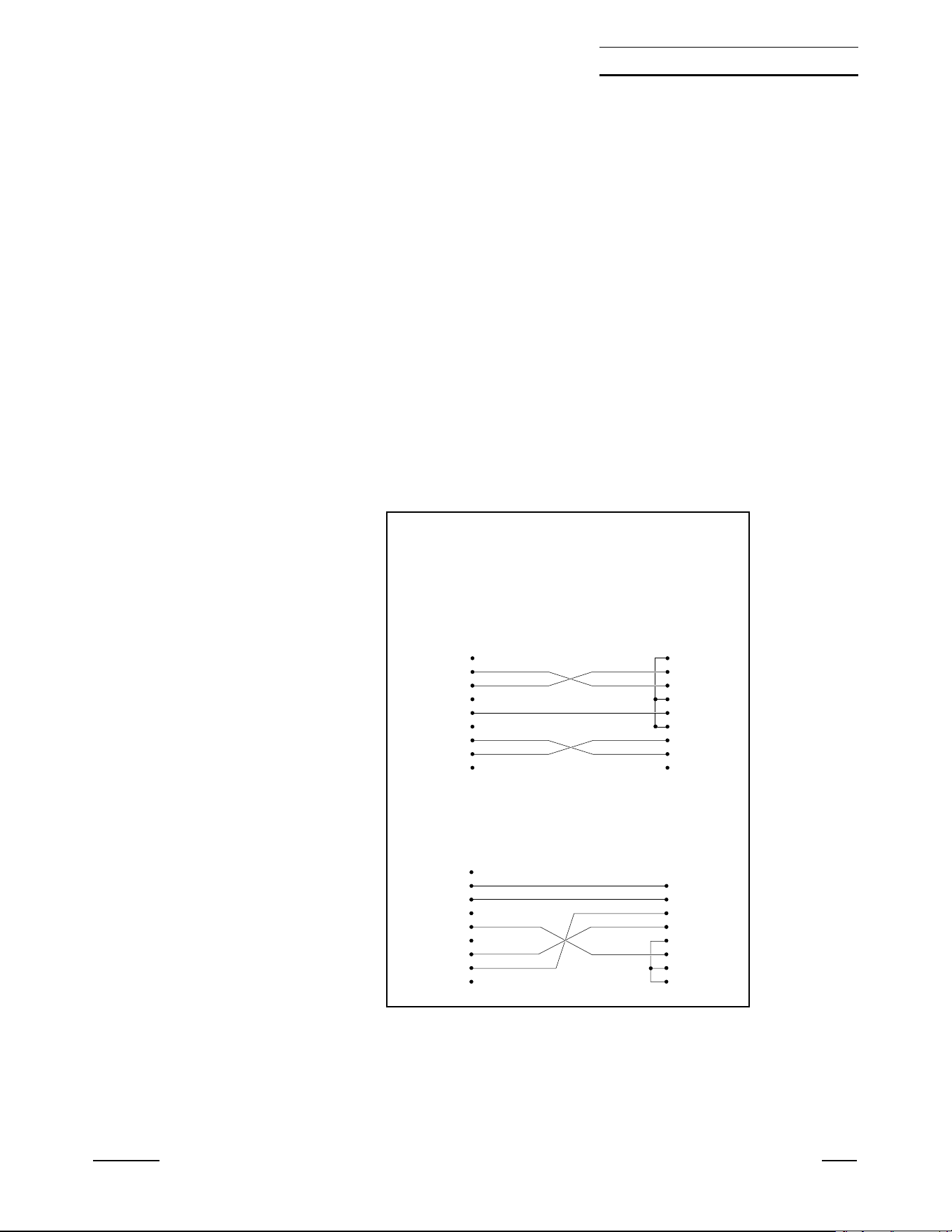
The 1502A is equipped with an RS-232 serial port. The RS-232 interface is
useful for connecting the 1502A to most any microcomputer. The RS-232
socket is located on the back panel of the 1502A. Wiring of the interface cable
should be as shown in Figure 6 below. To eliminate noise, the serial cable
should be shielded with low resistance between the connector (DB-9) and the
shield. The protocol for RS-232 communications is 8 data bits, 1 stop bit, and
no parity. The RS-232 interface uses RTS and CTS for flow control.
1502A Manual Rev. 952801 23
7 Digital Communications Interface
RS-232 Cable Wiring for
IBM PC and Compatibles
1NC
2RxD
3TxD
4NC
5GND
6NC
7RTS
8CTS
9NC
2TxD
3RxD
4RTS
5CTS
6
7GND
8
20
1502 Thermometer
Connector
(DB 9-Pin)
Computer (DTE)
Connector
(DB 25-Pin)
1NC
2RxD
3TxD
4NC
5GND
6NC
7RTS
8CTS
9NC
1NC
2RxD
3TxD
4NC
5GND
6NC
7RTS
8CTS
9NC
1502 Thermometer
Connector
(DB 9-Pin)
Computer (DTE)
Connector
(DB 9-Pin)
Figure 6 Serial Cable Wiring
1.888.610.7664 sales@GlobalTestSupply.com
Fluke-Direct.com

7.1.1 Setting the Baud Rate
The 1502A must be set to the same baud rate as the remote device. The baud
rate of the 1502A can be set to 1200, 2400, 4800, or 9600. The default is
2400. The baud rate is set in the Comm menu. Press the Menu button
(“SEt?” appears) then press the K/Comm button. The display will briefly indi-
cate “SErIAL”, then “bAUd” and then display the current baud rate. Use the U
and D buttons to increase or decrease the baud rate then press Enter. The
next parameter in the Comm menu, the serial sample period, will then appear.
7.1.2 Automatic Transmission of Measurements
The 1502A can be programmed to automatically send measurements to a re-
mote printer or terminal. The transmission interval is set using the “SA PEr”
sample period parameter. This is set in the Comm menu after the baud rate
parameter. The display will briefly indicate “SA PEr” and then display the cur-
rent sample period. The sample period is specified in hours, minutes, and sec-
onds. Setting the sample period to 0 disables automatic transmission of
measurements. Use the L and R buttons to move between digits. The se-
lected digit will flash. Use the U and D buttons to increase or decrease the
digit. When the sample period is set as desired press Enter.
The sample period can also be set using the “SA” communications command.
The period can be specified in seconds, in minutes and seconds, or in hours,
minutes, and seconds. For example, SA=15<EOS> causes the 1502A to
transmit measurements at 15-second intervals. SA=10:00<EOS> causes the
1502A to transmit a measurement every ten minutes. SA=2:00:00<EOS>
causes the 1502A to transmit a measurement every two hours. (<EOS> repre-
sents the termination character which is either a linefeed or carriage return).
7.1.3 Time Stamp and System Clock
The 1502A has a built-in system clock that counts hours, minutes, and sec-
onds while the power is on. The clock can be used to time stamp measure-
ment data read from the communications interfaces. When the power is
switched on the clock is set to 00:00:00. You can set the clock to show the ac-
tual time-of-day. This can be done within the Comm menu. Press the Menu
button (“SEt?” appears) and then the Comm menu button. The display will
briefly show “CLOC” then the current clock time in hours, minutes, and sec-
onds. The time is represented in 24-hour format with 00 hours meaning 12:00
a.m. and 23 hours meaning 11:00 p.m. Use the L and R buttons to move
between digits. The selected digit will flash. Use the U and D buttons to
change the digit. Once the digits are correct, press Enter to accept the new
time. If you decide not to change the time press the Exit button instead.
The clock can also be set using the “CL” communications command:
CL=hh:mm:ss <EOS>.
The time stamp allows you to record the time-of-day with measurements that
are printed or transmitted to a computer. The given time is the value of the
system clock at the time of transmission. An example of time-stamped read
-
ings is shown below.
t: 31.787 F 14:04:40
24 Manual Rev. 952801 Hart Scientific
7 Digital Communications Interface
1.888.610.7664 sales@GlobalTestSupply.com
Fluke-Direct.com

t: 31.788 F 14:04:50
t: 31.792 F 14:05:00
t: 31.793 F 14:05:10
The time stamp control is also accessed in the Comm menu. Press the Menu
button (“SEt?” appears) and then the Comm menu button. Press Exit to skip
to the time stamp parameter. The display will briefly show “ti Sta” then the
time stamp state which is either ON or OFF. Use the U and D buttons to
change the state and press Enter. ON enables transmission of the time stamp
and OFF disables it.
The time stamp can also be set using the “ST” communications command.
The command ST=ON<EOS> enables the time stamp and ST=OF<EOS> dis-
ables it.
The clock and time stamp parameters affect the time stamp of data read
through both the RS-232 and IEEE-488 interfaces.
7.1.4 Duplex Mode and Linefeed
Commands sent to the 1502A through the RS-232 interface are normally ech-
oed back to the remote device. To disable this feature set the duplex option to
half instead of full. The duplex parameter is found in the Comm menu after the
sample period parameter. The display will briefly indicate “dUPL” and then dis-
play the current duplex setting. Use the U and D buttons to set duplex to
“HaLF” or “FULL” then press Enter.
Duplex can also be set using the “DU” communications command. The com-
mand DU=H<EOS> sets duplex to half and DU=F<EOS> sets duplex to full.
Transmissions from the 1502A through the RS-232 interface are normally fol-
lowed by a linefeed character (ASCII decimal 10). The linefeed character can
be disabled by setting the linefeed “LF” parameter to “OFF”. The linefeed pa-
rameter is found in the Comm menu after the duplex parameter. The display
will briefly indicate “LF” and then display the current linefeed setting. Use the
U and D buttons to set linefeed “On” or “OFF” then press Enter.
The linefeed can also be set using the “LF” communications command. The
command LF=OF<EOS> disables the linefeed character and LF=ON<EOS>
enables it.
7.2 GPIB Interface
The 1502A is available with an optional IEEE-488 (GPIB) port. The IEEE-488
interface is useful when one computer needs to control and collect data from
many instruments simultaneously. The IEEE-488 connector is located on the
back panel of the 1502A above the RS-232 connector. To eliminate noise, the
GPIB cable should be shielded.
The 1502A is equipped with basic communication capabilities as specified in
IEEE-488.1. The particular capabilities of the IEEE-488 interface are AH1,
SH1, T6, L4, DC1 (TE0, LE0, SR0, RL0, PP0, DT0). Refer to “IEEE Std
488.1-1987". The 1502A can talk and listen and accepts the DCL and SDC
clear commands. The 1502A does not respond to trigger (GET), serial poll,
parallel poll, or remote/local commands and is not capable of talk-only mode.
1502A Manual Rev. 952801 25
7 Digital Communications Interface
1.888.610.7664 sales@GlobalTestSupply.com
Fluke-Direct.com

7.2.1 Setting the Address
The IEEE-488 bus requires that each device has a unique address. The de
-
fault address of the 1502A is 22 but can be changed if necessary. The
IEEE-488 address of the 1502A is set within the Comm menu after the serial
linefeed parameter. (This menu option will not appear if the IEEE-488 interface
is not installed). Press the Menu button (“SEt?” appears) then press the
Comm button. The display will briefly indicate “SErIAL”, then “bAUd” and then
display the current baud rate. Press Enter several times until “IEEE” appears.
The display will briefly indicate “AddreSS” and then display the current
IEEE-488 address. Use the U and D buttons to change the number then
press Enter.
7.2.2 Setting the Termination Character
The 1502A will normally terminate transmissions from the IEEE-488 port with a
linefeed (newline) character. Some systems may require a terminating car-
riage return instead. The termination character can be changed if necessary.
The termination character is set within the Comm menu after the IEEE-488
address parameter. (This menu option will not appear if the IEEE-488 interface
is not installed). The display will briefly indicate “EOS” (end of string) and then
display the current setting. Use the U and D buttons to change the termina-
tion character then press Enter.
7.2.3 Time Stamp
Measurement data read from the GPIB interface can be stamped with the
time-of-day. For instructions on setting the time stamp and system clock see
Section 7.1.3 above.
7.3 Remote Commands
ASCII commands are used to instruct the 1502A to perform certain actions.
Table 5 provides a complete list of commands. These commands can be used
with either the RS-232 or IEEE-488 interface. All commands sent to the 1502A
must be terminated with a carriage return or linefeed. Either upper or lower
case letters are accepted. Commands used to set a parameter are issued with
the command header, an “=“ character, and the parameter value. For example,
U=C<EOS> sets the units to Celsius. (The symbol <EOS> represents the ter-
mination character.) Commands used to request data are issued with only the
command header. For example, T<EOS> causes the 1502A to return the most
recent measurement. Basic operations using commands are explained in the
following sub-sections.
7.3.1 Measurement Commands
The following commands relate to reading measurement data.
26 Manual Rev. 952801 Hart Scientific
7 Digital Communications Interface
1.888.610.7664 sales@GlobalTestSupply.com
Fluke-Direct.com

1502A Manual Rev. 952801 27
7 Digital Communications Interface
Command Description
Measurement Commands
T read measurement (includes label, unit, and time)
F[ETCH?] read measurement value (SCPI compatible)
SA[=[[[hh:]mm:]ss] read [or set] serial sample period
U=C|F|K|O select units
ST[=ON/OF] read [or set] the time stamp
CL[=hh:mm:ss] read [or set] the system clock
Probe Characterization Commands
PR[=90|68|R|S] read [or select] the characterization type
R0[=<value>] read [or set] R0 or R(0.01°C) depending on the selected charac-
terization
AL[=<value>]
read [or set] α for the Callendar-Van Dusen or IPTS-68 character-
ization
DE[=<value>]
read [or set] δ for the Callendar-Van Dusen or IPTS-68 character-
ization
BE[=<value>]
red [or set] β for the Callendar-Van Dusen characterization
A4[=<value>] read [or set]
a
4
for the ITS-90 or IPTS-68 characterization
B4[=<value>] read [or set]
b
4
for the ITS-90 characterization
C4[=<value>] read [or set]
c
4
for the IPTS-68 characterization
A
n
[=<value>] read [or set]
a
6
, a
7
, a
8
, a
9
, a
10
, or
a
11
for the ITS-90 characteriza-
tion
B
n
[=<value>] read [or set]
b
6
, b
7
, b
8
,
or
b
9
for the ITS-90 characterization
C
n
[=<value>] read [or set]
c
6
or
c
7
for the ITS-90 characterization
D6[=<value>] read [or set]
d
6
for the ITS-90 characterization
SC[=68/90] read [or set] IPTS-68 scale conversion
CO=<value> test resistance to temperature conversion
Sample Parameter Commands
FI[=<value>] read [or set] filter time constant
CU[=<value>] read [or set] probe current
PS[=<value.] read [or set] the power saver period
Table 5 Command List
1.888.610.7664 sales@GlobalTestSupply.com
Fluke-Direct.com

7.3.1.1 Reading Temperature
The most recent temperature measurement can be read using the following
command:
T<EOS> reads the most recent measurement
The syntax of the response is as follows:
t:_nnnn.nnn_u
or
t:_nnnn.nnn_u_hh:mm:ss
The _’s represent space characters. The n’s represent the digits of the mea-
surement value. If fewer digits are needed the leading positions are filled with
space characters. The u represents the unit which is either ‘C’, ‘F’, ‘K’, or ‘O’
(for ohms). The time stamp appears if this option is enabled (see Section
7.3.1.4 below). The time appears in 24-hour format with two digits each for
hours, minutes, and seconds.
The following SCPI compatible command can also be used to return the most
recent measurement but without the label and unit.
FETC?<EOS> or
FETCH?<EOS> returns the value of the most recent measurement
28 Manual Rev. 952801 Hart Scientific
7 Digital Communications Interface
Command Description
Communication parameter commands
DU[=F/H] read [or set] serial sample duplex mode
LF[=ON/OF] read [or set] serial linefeed
Calibration Commands
*PA=<password> disable password lockout of calibration commands
*LO=[=CA|AL] read [or set] menu lockout
*C0[=<value>]
read [or set] the 0Ω calibration parameter
*C1[=<value>]
read [or set] the 100Ω calibration parameter
*C4[=<value>]
read [or set] the 400Ω calibration parameter
*SN[=<value>] read [or set] the instrument serial number
Miscellaneous Commands
*VER read model number and firmware version number
IDN? read manufacturer, model number, serial number, and firmware
version number (SCPI compatible)
H read a list of commands
Command List Continued
1.888.610.7664 sales@GlobalTestSupply.com
Fluke-Direct.com

7.3.1.2 Automatically Transmitting Measurements
By setting the sample period, the 1502A can be programmed to automatically
transmit measurements from the RS-232 port at specified intervals. The sam
-
ple period can be set remotely using the commands:
SA=[[hh:]mm:]ss<EOS> sets the sample period
SA=0<EOS> disables automatic transmission of measurements
The value of the sample period can be from 0 seconds to 24 hours. It is not
necessary to give hours or minutes for values in seconds. A value of 0 dis-
ables automatic transmission of measurements. Following are some example
commands.
SA=10<EOS> sets the sample period to 10 seconds
SA=5:00<EOS> sets the sample period to 5 minutes
SA=1:00:00<EOS> sets the sample period to 1 hour
7.3.1.3 Selecting the Unit of Measurement
The selected unit is used in displaying measurements on the front panel and in
reading measurements from the communications interfaces. The following
commands can be used to select the unit of measurement:
U=C<EOS> selects Celsius
U=F<EOS> selects Fahrenheit
U=K<EOS> selects Kelvin
U=O<EOS> selects ohms
7.3.1.4 Enabling the Time Stamp
Enabling the time stamp causes the time of the system clock to be transmitted
along with measurement data. The time stamp can be enabled or disabled us-
ing the following commands:
ST=ON<EOS> enables the time stamp
ST=OFF<EOS> disables the time stamp
7.3.1.5 Setting the Clock
The system clock is set in 24-hour format using the command:
CL=hh:mm:ss<EOS>
For example:
CL=14:24:00 sets the time to 2:24 pm.
7.3.2 Probe Characterization Commands
The following commands relate to reading measurement data.
7.3.2.1 Selecting the Characterization
The following commands can be used to select the probe characterization and
coefficients:
P=90<EOS> selects the ITS-90 characterization
1502A Manual Rev. 952801 29
7 Digital Communications Interface
1.888.610.7664 sales@GlobalTestSupply.com
Fluke-Direct.com

P=68<EOS> selects the IPTS-68 characterization
P=R<EOS> or P=S<EOS> selects the standard Callendar-Van Dusen
characterization
R0=<value><EOS> sets R
0
or R(0.01C) depending on the selected char-
acterization
AL=<value><EOS> sets α for the Callendar-Van Dusen or IPTS-68 char-
acterization
DE=<value><EOS> sets δ for the Callendar-Van Dusen or IPTS-68 char-
acterization
BE=<value><EOS> sets β for the Callendar-Van Dusen characterization
A4=<value><EOS> sets
a
4
for the ITS-90 or IPTS-68 characterization
B4=<value><EOS> sets
b
4
for the ITS-90 characterization
C4=<value><EOS> sets
c
4
for the IPTS-68 characterization
A
n
=<value><EOS> sets
a
6
,
a
7
,
a
8
,
a
9
,
a
10
, or
a
11
for the ITS-90 character-
ization.
n
is a number from 6 to 11.
B
n
=<value><EOS> sets
b
6
,
b
7
,
b
8
, or
b
9
for the ITS-90 characterization.
n
is a number from 6 to 9.
C
n
=<value><EOS> sets
c
6
, or
c
7
for the ITS-90 characterization.
n
is 6 or
7.
D6=<value><EOS> sets
d
6
for the ITS-90 characterization
SC=69<EOS> or SC=90<EOS> sets the temperature scale for the
IPTS-68 characterization
7.3.2.2 Testing the Characterization
The following command can be used to test the probe characterization:
CO=<value><EOS> returns a temperature calculated from resistance
The 1502A will respond with a temperature value computed from the given re-
sistance value. The temperature is given in the currently selected unit. As an
example, if the Callendar-Van Dusen characterization is selected with IEC-751
coefficients and the selected unit is Celsius, sending this command with a re-
sistance value of 138.5 will return a temperature value of 100.0°C.
7.3.3 Sample Commands
The following commands ralate to the measurement process.
7.3.3.1 Setting the Filter
The filter helps to reduce variations in the measurements. The filter can be set
remotely using the command:
FI=<value><EOS> sets the filter time constant
FI=0<EOS> disables the filter
The value is the filter time constant in seconds. It must be between 0 and 60
inclusive. A value of 0 disables the filter.
7.3.3.2 Setting the Probe Current
The probe excitation current can be set remotely using the commands:
30 Manual Rev. 952801 Hart Scientific
7 Digital Communications Interface
1.888.610.7664 sales@GlobalTestSupply.com
Fluke-Direct.com

CU=1<EOS> sets the current to 1 mA
CU=.5<EOS> sets the current to 0.5 mA
7.3.3.3 Setting the Power Saver
Activating the power saver can conserve power which is an advantage when
operating from a battery. The power saver causes the display to blank if no
front panel buttons are pressed for a given number of minutes. The power
saver can be set using the commands:
PS=<value><EOS> sets the power saver time in minutes
PS=0<EOS> or PS=OF<EOS> disables the power saver
The value is the power saver time-out period in minutes. It must be between 0
and 60 inclusive. It is automatically rounded to a multiple of five minutes. A
value of 0 or OFF disables the power saver.
7.3.4 Communication Commands
The following commands relate to external communications.
7.3.4.1 Setting the Duplex Mode
When the RS-232 duplex mode is set to FULL all commands received by the
1502A from the RS-232 port are echoed back. Setting the mode to HALF dis-
ables the echo. The duplex mode can be set remotely using the commands:
DU=F<EOS> sets duplex to full
DU=H<EOS> sets duplex to half
7.3.4.2 Setting the Linefeed Option
When the RS-232 linefeed option is enabled any data transmitted from the
RS-232 port is terminated with a carriage return and a linefeed. Disabling the
linefeed sets the termination to carriage return only. The linefeed option can be
set remotely using the commands:
LF=ON<EOS> enables linefeed
LF=OF<EOS> disables linefeed
7.3.5 Calibration Commands
The following commands are used in calibrating the instrument.
7.3.5.1 Entering the Password
In order to set the calibration parameters the password must be issued first.
The following command enables access to the calibration parameters:
*PA=2051<EOS> enables the calibration commands
Calibration parameters can be locked out again by sending *PA=0 or by cy-
cling the power.
7.3.5.2 Setting the Menu Lockout
The following commands can be used to select the menu lockout options:
1502A Manual Rev. 952801 31
7 Digital Communications Interface
1.888.610.7664 sales@GlobalTestSupply.com
Fluke-Direct.com

*LO=CA<EOS> locks out only the calibration menu
*LO=AL<EOS> locks out all menus
7.3.5.3 Setting the Calibration Coefficients
The instrument calibration coefficients are used to maintain the resistance
measurement accuracy of the 1502A. These coefficients must not be changed
except by a qualified technician during the calibration of the 1502A. The fol-
lowing commands can be used to set the instrument calibration coefficients:
*C0=<value><EOS> sets the calibration parameter CAL0
*C1=<value> <EOS> sets the calibration parameter CAL100
*C4=<value><EOS> sets the calibration parameter CAL400
7.3.5.4 Setting the Serial Number
The following command is used to set the serial number of the 1502A:
*SN=<value><EOS> sets the instrument’s serial number
7.3.6 Other Commands
Remaining commands are described below.
7.3.6.1 Instrument Identification
The following command returns the model number and firmware version num-
ber:
*VER<EOS> returns the model and firmware version numbers
The syntax of the response is as follows:
ver.
mmmmm,v.vv
The
m
’s represent digits of the model number. The
v
’s represent the digits of
the firmware version number. As an example, if the version number was 1.10
the response would be “ver.1502A,1.10".
The following IEEE-488.2 and SCPI compatible command can be used to read
the manufacturer, model number, serial number, and firmware version number.
*IDN?<EOS> returns identification data for the instrument
The syntax of the response is as follows:
HART,1502A,<
serial number>,v.vv
The
v
’s represent the digits of the firmware version number. As an example, if
the serial number was 6A1202 and the version number was 1.10 the response
would be “HART,1502A,6A1202,1.10".
7.3.6.2 Reading a List of Commands
The following command returns a list of commands:
H<EOS>
or
HELP<EOS> returns a list of commands
32 Manual Rev. 952801 Hart Scientific
7 Digital Communications Interface
1.888.610.7664 sales@GlobalTestSupply.com
Fluke-Direct.com

8 Calibration Procedure
The 1502A uses a three-point calibration scheme with a quadratic polynomial
correction function to maintain the accuracy of its resistance measurement.
The three calibration points are at 0Ω, 100Ω, and 400Ω. Three calibration pa-
rameters determine the correction function: CAL0, CAL100, and CAL400. The
CAL0 parameter sets the correction at 0Ω resistance (but does not affect the
correction at 100Ω). The CAL100 parameter sets the correction at 100Ω resis-
tance (but does not affect the correction at 0Ω). The CAL400 parameter sets
the correction at 400Ω resistance (but does not affect the correction at 0 and
100Ω). Adjusting the calibration parameters directly affects the measurement
at the specific resistances. For example, increasing the CAL100 parameter by
0.005 increases the measured value at 100Ω by 0.005Ω.
8.1 Accessing the Calibration Parameters
The calibration parameters are accessed in the Cal menu. The calibration pa-
rameters are protected by requiring the correct password to access them.
Press the Menu button, “SEt?” appears. Press the Ω/Exit button and hold it
down for one second, “CAL” appears briefly. The display will show “PA= 0000”
and allow you to change the number to the correct password. You must enter
the password (“2051”). Use the L and R buttons to move between the
password digits and the U and D buttons to increase or decrease the value
of a digit. Press Enter when all the digits are correct. If the password is en-
tered correctly the first parameter in the calibration menu will appear.
The first parameter in the Cal menu is the lockout control parameter, indicated
on the display as “LOCOUt”. This parameter has two options, “CAL” and “ALL”.
“CAL” (default) locks out the calibration menu only. “ALL” locks out all menus
and access to any menu requires the correct password. Use the L and R
buttons to select the lockout option and press Enter to continue. The instru-
ment calibration parameters follow.
The calibration parameters appear with the name shown briefly then the value.
You can change the sign and digits of each parameter. Use the L and R
buttons to move between digits and the U and D buttons to increase or de-
crease the value of the digit. Press Enter to save the new value.
The last parameter in the Cal menu is the factory reset function. This can be
used to clear the internal memory and reset all parameters to the defalut val-
ues. This is intended to be used only at the factory.
The calibration parameters can also be set using remote commands through
the RS-232 or IEEE-488 interface. The *PA=<password><EOS> command
must be used first, using the correct password (“2051”), to enable access to
the calibration parameters. Lockout protection is automatically set by cycling
the power. The *C0=<value><EOS>, *C1=<value> <EOS>, and
*C4=<value><EOS> commands can be used to set the values of the CAL0,
CAL100, and CAL400 parameters respectively.
1502A Manual Rev. 952801 33
8 Calibration Procedure
1.888.610.7664 sales@GlobalTestSupply.com
Fluke-Direct.com

8.2 Calibration Procedure
Calibration requires four-wire 100Ω and 400Ω resistors of 10 ppm accuracy
and a 0Ω resistor (or short). For verification, 25Ω and 200Ω resistors of 10
ppm accuracy are also required. The resistors are connected to the input the
same way probes are. The calibration procedure is as follows:
1.
Connect a 0Ω resistor to the input and measure its resistance. Note the av-
erage error in the measurement. Adjust the CAL0 parameter by subtracting
the measured error. For example, if the input is exactly 0.0000Ω and read-
out shows –0.0011Ω, the CAL0 parameter should be adjusted by adding
0.0011 to it.
2.
Connect a 100Ω resistor to the input and measure its resistance. Note the
average error in the measurement. Adjust the CAL100 parameter by sub-
tracting the measured error. For example, if the input is exactly 100.000Ω
and the readout shows 100.029Ω, the CAL100 parameter should be ad-
justed by subtracting 0.029 from it.
3.
Connect a 400Ω resistor to the input and measure its resistance. Note the
average error in the measurement. Adjust the CAL400 parameter by sub-
tracting the measured error. For example, if the input is exactly 400.000Ω
and the readout shows 399.991Ω, the CAL400 parameter should be ad-
justed by adding 0.009 to it.
4.
Verify the accuracy at 0Ω,25Ω , 100Ω, 200Ω, and 400Ω. The accuracy
should be within the short-term accuracy limits given in the specifications.
34 Manual Rev. 952801 Hart Scientific
8 Calibration Procedure
1.888.610.7664 sales@GlobalTestSupply.com
Fluke-Direct.com

9 Maintenance
•
The calibration instrument has been designed with the utmost care. Ease
of operation and simplicity of maintenance have been a central theme in
the product development. Therefore, with proper care the instrument
should require very little maintenance. Avoid operating the instrument in
an oily, wet, dirty, or dusty environments.
•
If the outside of the instrument becomes soiled, it may be wiped clean with
a damp cloth and mild detergent. Do not use harsh chemicals on the sur-
face which may damage the paint or the plastic of the outside shell.
•
If a hazardous material is spilt on or inside the equipment, the user is re-
sponsible for taking the appropriate decontamination steps as outlined by
the national safety council with respect to the material.
•
If the mains supply cord becomes damaged, replace it with a cord with the
appropriate gauge wire for the current of the instrument. If there are any
questions, call Hart Scientific Customer Service for more information.
•
Before using any cleaning or decontamination method except those rec-
ommended by Hart, users should check with Hart Scientific Customer Ser-
vice to be sure that the proposed method will not damage the equipment.
•
If the instrument is used in a manner not in accordance with the equipment
design, the operation of the thermometer may be impaired or safety haz-
ards may arise.
1502A Manual Rev. 952801 35
9 Maintenance
1.888.610.7664 sales@GlobalTestSupply.com
Fluke-Direct.com

10 Troubleshooting
In case you run into difficulty while operating the 1502A, this section provides
some suggestions that may help you solve the problem. Below are several sit-
uations that may arise followed by possible causes of the problem and sug-
gested actions you might take.
Incorrect Temperature Reading
While attempting to measure temperature the display shows an incorrect
value.
If the temperature readings seem to be incorrect you should first check to see
if the resistance is being measured correctly. Select ohms to display resis-
tance. If the resistance is incorrect refer to the next subsection for trouble-
shooting incorrect resistance readings. If the resistance is being measured
correctly but the displayed temperature value is incorrect consider the follow-
ing possibilities.
•
One or more coefficients are incorrect. This is a common mistake.
While entering coefficients it is easy to miss a digit or sign. Check all the
values carefully comparing them with the values on the calibration certifi-
cate for the probe.
•
The selected conversion type is incorrect. Check to make sure the cor-
rect conversion type (ITS-90, RTD, or IPTS-68) is selected.
• The measurement is out of range. The 1502A may not be able to calcu-
late temperature accurately if the resistance is outside the valid range. The
measured resistance may be too low or too high if the actual temperature
is too low or too high or if there is a problem with the sensor (see below).
Incorrect Resistance Reading
While attempting to measure resistance the display shows an incorrect value.
Consider the following possibilities.
•
Poor or incorrect connection of the probe. Acommon mistake is to con-
nect the wires of the probe to the wrong terminals. Check the wiring care-
fully (see Figure 1 on page 10).
•
Open, shorted, or damaged sensor or lead wires. Check the resistance
across the sensor using a hand-held DMM. Also check the resistance be-
tween common pairs of leads. Check to make sure there is no conductivity
between any of the leads and the probe sheath. Use a good-quality sensor
to avoid errors caused by drift, hysteresis, or insulation leakage.
•
Electrical interference. Intense radio-frequency radiation near the
1502A or the probe can induce noise into the measurement circuits result-
ing in erratic readings. The 1502Ais intended to operate in a laboratory en-
vironment with limited radio-frequency noise. If interference seems to be a
problem you might try eliminating the source of interference or moving the
1502A to a different location. A well-grounded, shielded cable should be
used for the probe leads.
•
Stem conduction error. The problem may be that the actual temperature
of the sensor is not what you expect. This is often the result of stem con
-
duction where heat flowing through the stem of the probe to ambient af
-
fects the temperature of the probe. It is very important that immersion
1502A Manual Rev. 952801 37
10 Troubleshooting
1.888.610.7664 sales@GlobalTestSupply.com
Fluke-Direct.com

probes be inserted to an adequately depth into the material being mea
-
sured. Measuring temperature using a surface sensor can be especially
difficult as the sensor is directly exposed to ambient.
Error Message at Power Up
The 1502A reports an error during the power up self-test.
On power up the 1502A performs a self-test of several of its key components.
A failure of a component will cause an error message to be displayed such as
“Err 4”. The possible error messages and their meanings are as follows:
Err 1
Static RAM failure.
Err 2
Nonvolatile RAM failure.
Err 3
Internal data structure error.
Err 4
ADC initialization failure.
Err 5
ADC operation error.
Generally, each of these conditions require a qualified factory technician to re-
place a faulty component. Contact the factory for assistance. One possible ex-
ception might be if a large static discharge nearby disturbs the circuits. Cycling
the power off and back on again may allow the 1502A to resume normal oper-
ation. Another might be if the AC source voltage is incorrect, e.g. using 115 V
when the 1502A is configured for 230 V. Check the source voltage and the
1502A’s configuration and make sure they agree.
38 Manual Rev. 952801 Hart Scientific
10 Troubleshooting
1.888.610.7664 sales@GlobalTestSupply.com
Fluke-Direct.com