
PREMIER 12/24V 6400A WHEELED ROADSTART®
JUMP STARTER
MODEL NO: PRS6400
Thank you for purchasing a Sealey product. Manufactured to a high standard, this product will, if used according to these instructions,
and properly maintained, give you years of trouble free performance.
IMPORTANT: PLEASE READ THESE INSTRUCTIONS CAREFULLY. NOTE THE SAFE OPERATIONAL REQUIREMENTS, WARNINGS & CAUTIONS. USE
THE PRODUCT CORRECTLY AND WITH CARE FOR THE PURPOSE FOR WHICH IT IS INTENDED. FAILURE TO DO SO MAY CAUSE DAMAGE AND/OR
PERSONAL INJURY AND WILL INVALIDATE THE WARRANTY. KEEP THESE INSTRUCTIONS SAFE FOR FUTURE USE.
1. SAFETY
1.1. ELECTRICAL SAFETY FOR SMART CHARGER FOR CHARGING ROADSTART BATTERIES
WARNING! It is the user’s responsibility to check the following:
Check all electrical equipment and appliances to ensure that they are safe before using. Inspect power supply leads, plugs and
all electrical connections for wear and damage. Sealey recommend that an RCD (Residual Current Device) is used with all electrical
products.
If this product is used in the course of business duties, it must be maintained in a safe condition and routinely PAT (Portable
Appliance Test) tested.
Electrical safety information. It is important that the following information is read and understood.
1.1.1. Ensure that the insulation on all cables and on the appliance is safe before connecting it to the power supply.
1.1.2. Regularly inspect power supply cables and plugs for wear or damage and check all connections to ensure that they are secure.
1.1.3. Important: Ensure that the voltage rating on the appliance suits the power supply to be used and that the plug is tted with the
correct fuse - see fuse rating in these instructions.
8 DO NOT pull or carry the appliance by the power cable.
8 DO NOT pull the plug from the socket by the cable. Remove the plug from the socket by maintaining a rm grip on the plug.
8 DO NOT use worn or damaged cables, plugs or connectors. Ensure that any faulty item is repaired or replaced immediately by a
qualied electrician.
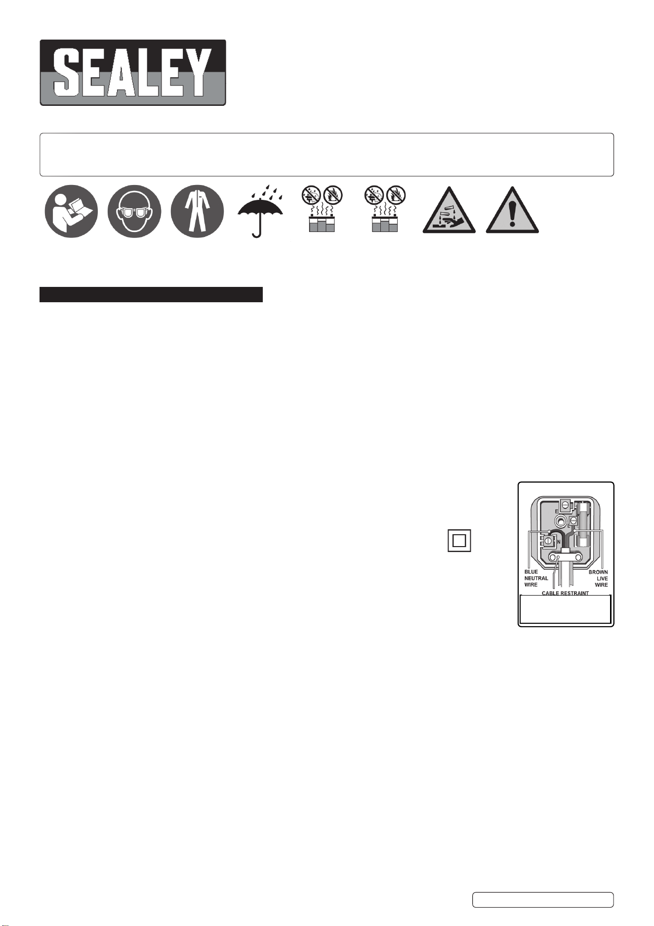
1.1.4. This product is tted with a BS1363/A 3 pin plug.
If the cable or plug is damaged during use, switch off the electricity supply and remove from use.
Replace a damaged plug with a BS1363/A 3 pin plug. If in doubt contact a qualied electrician.
Class II products are wired with live (brown) and neutral (blue) only and are marked with the
Class II symbol;
A) Connect the BROWN live wire to the live terminal ‘L’.
B) Connect the BLUE neutral wire to the neutral terminal ‘N’.
C) After wiring, check that there are no bare wires and ensure that all wires have been correctly connected.
Ensure that the cable outer sheath extends inside the cable restraint and that the restraint is tight.
DO NOT connect either wire to the earth terminal.
Sealey recommend that repairs are carried out by a qualied electrician.
1.2. GENERAL SAFETY
Modern vehicles contain extensive electronic systems. You are required to check with the vehicle manufacturer, for any
specicinstructionsregardingtheuseofthistypeofequipmentoneachvehicle.
No liability will be accepted for damage/injury, where this product is not used in accordance with all instructions.
PLEASE SAVE THIS OWNER’S MANUAL AND READ BEFORE EACH USE.
9 This manual will explain how to use the unit safely and effectively. Please read and follow these instructions and precautions carefully.
9 If someone else uses the Roadstart, make they are well informed on how to use it safely, and have read and understood the operating
instructions. The longevity of the Roadstart depends on it.
9 Charge the Roadstart’s internal battery immediately after purchase, after each use and as often as possible. It is highly recommended
to leave the Roadstart permanently connected to the automatic charger.
9 Read the entire manual before using this product. Failure to do so could result in serious injury or death.
9 Keep out of reach of children.
9 This Roadstart is not intended for use by persons (including children) with reduced physical, sensory or mental capabilities, or lack
of experience and knowledge, unless they have been given supervision or instruction concerning the use of the Roadstart by a person
responsible for their safety.
9 This appliance can be used by children aged from 8 years and above and persons with reduced physical, sensory or mental
capabilities or lack of experience and knowledge if they have been given supervision or instruction concerning use of the appliance in
a safe way and understand the hazards involved.
9 Children shall not play with the appliance.
8 DO NOT put ngers or hands into the product.
8 DO NOT expose the Roadstart to rain or snow.
9 Use only recommended attachments. Use of an attachment not recommended or sold by Sealey may result in a risk of re, electric
shock or injury to persons or damage to property.
PRS6400 Issue 2 18/04/23
Original Language Version
© Jack Sealey Limited
Warning!Refer to
instruction
manual
Do not expose
to rain
Use in a well
ventilated area
Corrosive
substance
Keep away
from sparks
and ame -
battery could
emit explosive
gases
Wear eye
protection
Wear protective
clothing
Recommended fuse rating
5Amp

9 To reduce the risk of damage to the electric plug or cord, pull by the plug rather than the cord when disconnecting the Roadstart.
9 To reduce the risk of electric shock, unplug the Roadstart charger from the outlet before attempting any maintenance or cleaning.
Simply turning off the controls will not reduce this risk.
8 DO NOT operate the Roadstart or charger with a damaged output cable; have the damaged part replaced immediately by a qualied
service person.
9 If the supply cord is damaged, it must be replaced by the manufacturer, its service agent or similarly qualied persons in order to avoid
a hazard.
8 NEVER wait until the Roadstart is completely discharged before recharging.
8 DO NOT operate the Roadstart if it has received a sharp blow, been dropped or otherwise damaged in any way; take it to a qualied
service person.
8 DO NOT disassemble the Roadstart or charger; take it to a qualied service person when service or repair is required. Incorrect
reassembly may result in a risk of re or electric shock.
RISK OF EXPLOSIVE GASES. PREVENT FLAMES AND SPARKS. PROVIDE ADEQUATE VENTILATION DURING CHARGING.
WORKING IN THE VICINITY OF A LEAD-ACID BATTERY IS DANGEROUS. BATTERIES GENERATE EXPLOSIVE GASES
DURING NORMAL OPERATION. FOR THIS REASON, IT IS IMPORTANT THAT YOU FOLLOW THESE INSTRUCTIONS EACH
TIME YOU USE THE ROADSTART.
9 The Roadstart must be placed in a well-ventilated area.
9 To reduce the risk of a battery explosion, follow these instructions and those published by the battery manufacturer and the
manufacturer of any equipment you intend to use in the vicinity of the battery. Review the cautionary markings on these products and
on the engine.
1.3. PERSONAL PRECAUTIONS
RISK OF EXPLOSIVE GASES. A SPARK NEAR THE BATTERY MAY CAUSE A BATTERY EXPLOSION. TO REDUCE THE RISK
OF A SPARK NEAR THE BATTERY:
9 NEVER smoke or allow a spark or ame in the vicinity of a battery or engine.
8 DO NOT permit the internal battery of the Roadstart to freeze. Never charge a frozen battery.
9 When charging the internal battery, work in a well ventilated area and do not restrict the ventilation in any way.
9 Be sure the area around the battery is well ventilated while the Roadstart is being used.
9 Remove personal metal items such as rings, bracelets, necklaces and watches when working with a lead-acid battery. A lead-acid
battery can produce a short-circuit current high enough to weld a ring or the like to metal, causing a severe burn.
9 Be extra cautious, to reduce the risk of dropping a metal tool onto the battery. It might spark or short-circuit the battery or other
electrical part that may cause an explosion.
9 To prevent sparking, NEVER allow clamps to touch together or contact the same piece of metal.
9 Consider having someone close enough by to come to your aid when you work near a lead-acid battery.
9 Have plenty of fresh water and soap nearby in case battery acid contacts your skin, clothing or eyes.
9 Wear complete eye and body protection, including safety goggles and protective clothing. Avoid touching your eyes while working near
the battery.
9 If battery acid contacts your skin or clothing, immediately wash the area with soap and water. If acid enters your eye, immediately ood
the eye with cold running water for at least 10 minutes and get medical attention right away.
9 If battery acid is accidentally swallowed, drink milk, the whites of eggs or water. DO NOT induce vomiting. Seek medical attention
immediately.
2. INTRODUCTION
High performance 66Ah AGM battery, specially formulated to jump-start up to 8-cylinder engines, 9.0L diesel and 12.0L petrol. Highly durable
casing and totally portable thanks to a retractable handle and puncture proof wheels. Easy-to-read digital voltmeter. 0/12/24V Rotary switch for
spark-free connection. Supplied with heavy-duty brass clamps with inbuilt short circuit protection fuse (in the + clamp). Reverse polarity alarm,
both visual and audible. 12V Fused output socket can be used as a memory saver, as well as to power accessories such as mini compressors.
Supplied with an automatic 12/24V 7A smart charger and maintainer. Made in Switzerland.
3. SPECIFICATION
Model No: ................................................................PRS6400
Auxiliary Output: .........................................................1 x 12V
Cable & Clamp Length: .................................................. 1.7m
Cold Cranking Amps: ......................2500A(12V)/1250A(24V)
Peak Amps: .....................................6400A(12V)/3200A(24V)
4. FEATURES
1. Reverse polarity alarm
2. Voltmeter
3. Charge status
4. Circuit breaker
5. On/off 12/24V switch
6. Charging input/output socket
Fuse Location:
7. Positive clamp handle cover
8. Fuse
fig.
1
PRS6400 Issue 2 18/04/23
Original Language Version
© Jack Sealey Limited

4.1. REVERSE POLARITY ALARM
4.1.1. Will emit a sound and light when it detects a reverse polarity. It can only work with the ON/OFF switch turned off.
4.1.2. Always have the Roadstart turned OFF or disconnected before use.
4.1.3. Then connect the clamps to the vehicle’s terminals or battery and at this moment the alarm will emit a noise and light if it detects a
reverse polarity connection. If the clamps are properly connected, nothing will happen.
4.1.4. Then turn your unit ON, and select the proper voltage (12 or 24V), before jump starting your vehicle.
4.2. Always have your device turned OFF when not in use or when connecting your clamps to your vehicle or battery. Only turn it ON after
you made sure the clamps are properly connected to the vehicle. Once the vehicle has started please remove the Negative clamp
rst, then turn your ON/OFF switch OFF and then remove the positive clamp.
4.3. VOLTMETER
4.3.1. Will indicate the voltage of the Roadstart. Turn switch to 12V or 24V press test button g1.3.
4.3.2. If your Roadstart is below 12.7V, you need to recharge it.
4.3.3. When you leave your Roadstart connected on the vehicle for 10 seconds maximum, the voltmeter should read the voltage output
of the alternator, which will let you know if the alternator is working properly or not. (A working alternator has an output of
approximately 14V).
4.4. CHARGING OUTPUT SOCKET
Refer to section 8
4.5. ON/OFF 12/24V SWITCH
4.5.1. Switch in the centre (position OFF).
4.5.2. Select the proper voltage, refer to the battery of the vehicle (by reading the user manual of the vehicle itself). Once you have made
sure of the voltage, either turn the switch to 12V or 24V.
4.5.3. It is important to select the correct voltage to avoid damaging the vehicle, or Roadstart and to avoid any explosion due to over charge.
4.5.4. Before turning the Roadstart ON, make sure that the clamps are properly connected and that there is no reverse polarity. Then turn the
Roadstart ON to jump start the vehicle. Once the vehicle has started, please remove rst the negative clamp, turn the Roadstart OFF
and then remove the positive clamp.
5. OPERATION
5.1. Turn OFF the air conditioning, the radio and the lights before jump starting.
5.2. Always wear safety equipment before trying to jump start your vehicle. Make sure the area is well ventilated and that the terminals are
clean.
5.3. Make sure that your unit is fully charged before attempting to jump start.
5.4. Make sure the On/off switch is off.
5.5. Make sure that the cables are not in the path of moving parts in the vehicle’s engine bay.
5.6. The battery terminal not connected to the frame should be connected rst. The other terminal should be connected to the frame, far
from the battery and the fuel line.
5.7. After starting, remove the frame connection rst, then the connection from the battery in the same order.
5.8. JUMP STARTING
5.8.1. Connect the positive (red) clamp to the positive terminal.
5.8.2. Connect the negative (black) clamp to the frame of the vehicle (earth/ground).
5.8.3. Choose the voltage with the voltage selector switch.
5.8.4. Turn On/Off switch to the ON position.
5.8.5. Then start your engine and stay clear of the battery and the Start Roadstart while jump-starting. Make sure that it cannot fall inside the
engine compartment.
5.8.6. Once started, rst disconnect the black (negative) clamp, then turn the On/Off switch on OFF.
5.8.7. Then disconnect the red (positive) clamp.
5.8.8. Store both clamps immediately in their respective positions on the Roadstart’s casing.
5.8.9. Recharge the Jump Starter with the supplied automatic charger.
Important: Should the vehicle refuse to start within 10 seconds, have the Start Roadstart cool down for 3 minutes before the next
attempt. If it still doesn’t start, have your car battery or engine checked. It may be that the car battery is defective as well and refuses
to accept the current from the Jump Starter.
5.9. This Start Roadstart can also be used as a source of power. For example, you can use a 12V OBD Memory Saver cable or 12V LED
lights which can be connected to the input/output socket of the Roadstart.
5.10. Always recharge the Start Roadstart after use.
6. MAINTENANCE
6.1. No special maintenance is needed on any of the Start Roadstarts. The most important is to always make sure that your Battery Start
Roadstart or Hybrid Start Roadstart is always fully charged. Keeping your unit discharged would damage it and void the warranty.
6.2. Only use the supplied battery charger to recharge it.
6.3. Do not try to open the unit yourself. Have an authorized agent do it for you.
6.4. Keeping your unit clean and stored at room temperature. Extreme temperatures will damage the batteries.
6.5. When not in use for an extended period of time, always make sure it is fully charged (at least once a month.)
7. FREQUENTLY ASKED QUESTIONS
Q. Roadstart doesn’t have power at the clamps.
A. Check the On/Off switch, the 12/24V connector or that the Safety Fuse has not blown, g.1.8.
Check that the clamps are connected properly.
Q. The Roadstart is not taking the charge.
A. Please check the fuse inside the charger. Please also check that the charger is working by checking its voltage output on the
clamps with a voltmeter.
PRS6400 Issue 2 18/04/23
Original Language Version
© Jack Sealey Limited
Q. Can a battery, charger or clamp be replaced?
A. Yes, anything on this Roadstart can be repaired or replaced.
8. CHARGING THE ROADSTART
8.1. The charger is fully automatic, therefore will not overcharge the Roadstart.
8.2. Charge by connecting the charger to the Roadstart using the charging socket on the
front of the Roadstart.
8.3. Follow the Safety advice at the start of this manual.
8.4. SMART CHARGER SPECIFIC SAFETY
9 This charger is designed for charging various SLA batteries widely used in auto, motorcycle and other vehicle types with capacity
ranges from 12V 14Ah -225Ah or 24V 14Ah-110Ah. It also may be used with some WET, GEL and AGM etc. batteries. (Please refer to
your battery user manual for correct application and charging methods.) This device has a water resist and dust rating of IP65.
9 Make sure you have a 12V or 24V Lead-Acid battery and read battery user manual carefully.
9 Clean your battery terminals. Take care to keep corrosion from coming in contact with your eyes.
9 Be sure the area around the battery is well ventilated during the charging process. When the battery is being charged you may notice
bubbling in the uid caused by battery generated explosive gases during charging duration.
9 If your battery is the AutoFill type, the battery uid containers and lter cap must be left in place for the duration of charging.
9 Connect the crocodile clips to the battery in the following order:
a) First-connect the positive charging lead (red colour) to the positive terminal post.
b) Second-connect the negative lead (black colour) to the negative terminal post.
9 It is important to ensure that both crocodile clips are making good contact with the respective terminal posts.
9 When connected to the power supply, the device will reset itself automatically and will stay in standby state if no further modes are
selected.
9 Connect to mains power and then select the suitable charge mode to begin charging. If the battery leads are wrongly connected, the
pole-changing switch will ensure the battery and charger are not damaged. The fault indicator will light. In which case start from the
beginning again.
9 The charging lamp will now indicate charging or the maintenance lamp will indicate that the battery is fully charged.
9 If the full charge stage does not arrive in 120 hours (MAX), the charger must be disconnected manually.
9 For indoor use only.
WARNING: EXPLOSIVE GASES. Prevent ames or sparks. Provide adequate ventilation during charging.
9 Use battery charger on 12V or 24V14Ah -225Ah Lead-acid rechargeable battery only.
8 Not intended to supply power to a low voltage electrical system. Do not use it for any other purpose.
WARNING! DO NOT ATTEMPT TO CHARGE A NON-RECHARGEABLE BATTERY.
9 Use the correct power supply otherwise the function of the device may be affected.
8 DO NOT use the battery charger for charging dry-cell batteries as they may burst and cause injury to persons and damage to property.
8 DO NOT operate charger if the cable is damaged. Have a damaged cord repaired by the manufacturer or his agent.
8 DO NOT operate charger if charger case is broken. Take it to a qualied person for inspection and repair.
8 DO NOT disassemble charger, incorrect reassembly my result in electric shock or re.
9 Locate charger as far away from battery as cable will permit. Never place charger above battery being charged, gases from battery will
corrode and damage charger.
8 Never touch the battery clips together when the charger is energized.
9 Connect and disconnect DC output clips only after removing AC cord from electric outlet.
8 DO NOT face battery when making nal connection.
9 Connect the appropriate positive (red) DC clip to the positive battery post. (the battery post which is not connected to the automobile
chassis.)
9 Connect the negative (black) DC clip to the negative pole or the chassis away from the battery and away from the fuel line.
9 Disconnect the power supply before making or breaking connections to the battery.
9 The positive (red) battery terminal (not connected to the chassis) has to be connected rst. The negative (black) connection is to be
made to the negative pole or the chassis remote from the battery and fuel line. The battery charger is then to be connected to the
mains supply.
9 After charging, disconnect the battery charger from the mains supply, then remove the negative or chassis connection and the positive
battery connection in this order.
9 These chargers are not intended for use by persons (including children) with reduced physical, sensory or mental capabilities, or
lack of experience and knowledge, unless they have been given supervision or instruction concerning use of the appliance by a person
responsible for their safety.
9 Children should be supervised to ensure that they do not play with the charger.
PRS6400 Issue 2 18/04/23
Original Language Version
© Jack Sealey Limited

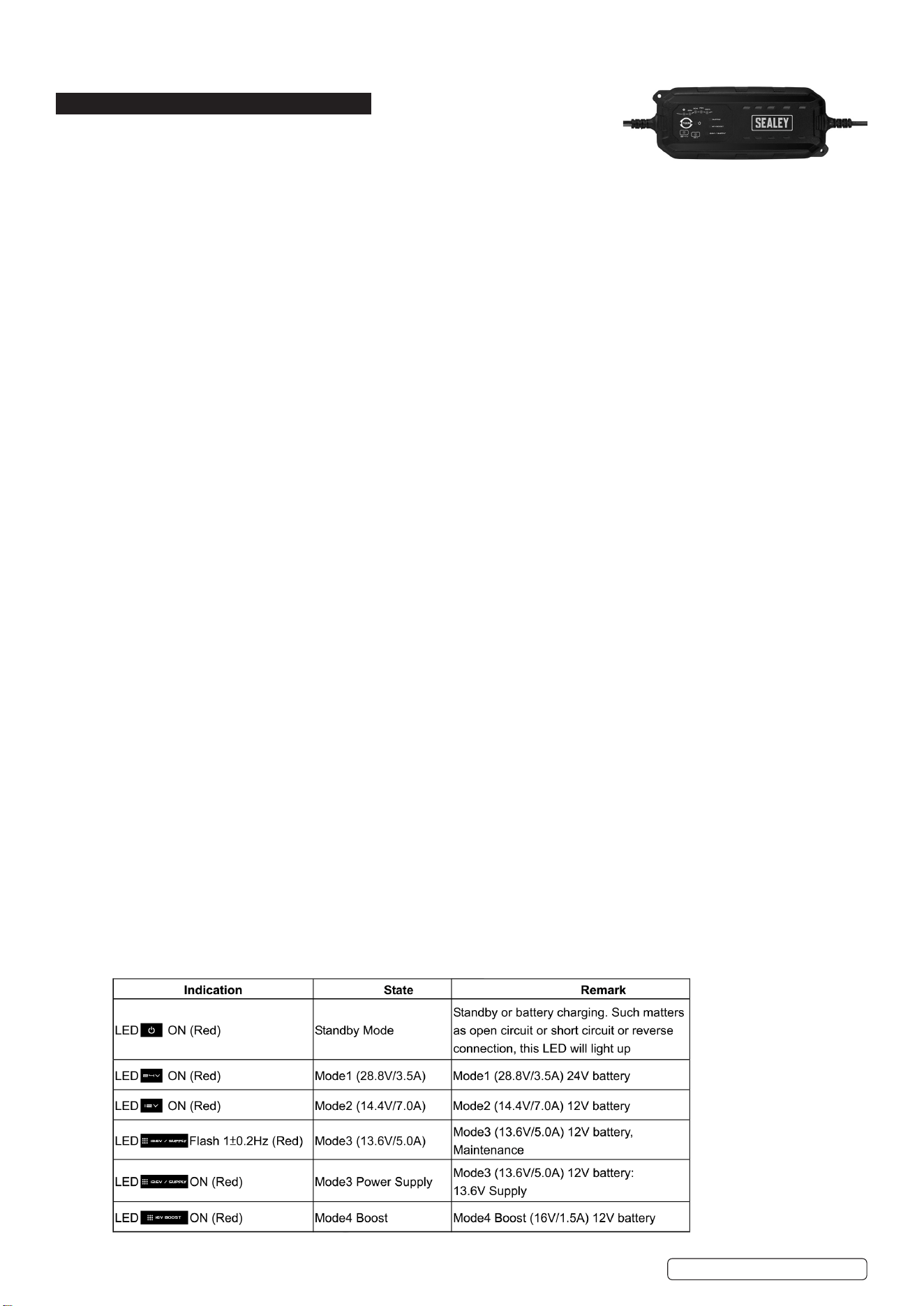
8.5. CHARGE LEDS
8.5.1. 4 red percentage charge LEDs. When charge = 100% charger enters Maintenance mode.
8.6. RESET
8.6.1. When connected to power supply device will reset itself to standby state if no other modes are selected.
8.7. MODE 1 (28.8V/3.5A) 24V BATTERY
8.7.1. Mainly used for batteries with larger capacity of more than 14Ah in normal condition.
8.7.2. Connect output terminals to battery with correct polarity and press MODE button to select 24V mode.
8.7.3. Corresponding 24V LED will light up together with % LED. Charging will begin with 3.5A±10% current. Light will remain on during
charging up to 28.8V±2%.
8.7.4. When battery is fully charged the charge 100% LED will turn on and a trickle current will maintain the battery.
8.8. MODE 2 (14.4/7A)
8.8.1. Mainly used for batteries with larger capacity of more than 14Ah in normal condition.
8.8.2. Connect output terminals to battery with correct polarity and press MODE button to select 12V mode.
8.8.3. Corresponding 12V LED will light up with % LED. Charging will begin with 7A±10% current. LED will remain on until battery is charged
up to 14.4V±0.25V.
8.8.4. When battery is fully charged the charge 100% LED will turn on and a trickle current will maintain the battery.
8.9. MODE 3 13.6V SUPPLY (13.6V/5.0A)
8.9.1. Mainly used for batteries with larger capacity of more than 14Ah in normal condition or to use as a 13.6V/5.0A power supply. The
charger has an overload protection feature (6.0A max.) If output voltage falls below 4.5V the charger returns to Standby mode.
CAUTION! There is no reversed polarity protection.
8.9.2. Maintenance 12V SLA batteries
Connect output terminals to battery with correct polarity and press MODE button to select the correct mode. The corresponding LED
13.6V/supply will light and the unit will supply ‘maintenance’ at 13.6±0.5V and 5A±10%.
8.9.3. Power source
Press MODE button for more than 3 seconds, LED 13.6V/supply will illuminate and the power source will supply 13.6V±0.5V and
5A ±10 constant voltage and current output.
8.10. MODE 4 16V boost (16V/1.5A) 12V battery only
8.10.1. For recovering batteries with a larger capacity of more than 14Ah in normal condition.
8.10.2. Connect output terminals to battery with correct polarity and press MODE button to select the correct mode. The corresponding
LED ‘16V boost’ will illuminate and the unit will start the recovery mode at 16.5V±0.5V and 1.5A±0.5A. If the battery is very at,
(deep discharged and sulphated, the LED ‘16V boost’ may continue to indicate for up to 3 hours whilst a special high voltage (about
17V maximum) is applied to force a xed current (1500mA) into the battery in a recovery attempt. After 4 hours maximum or as soon
as the battery can accept the normal charging programme, the LED ‘16V boost’ will ash with 0.5s on 1s off.
8.11. PULSE RESCUE DEAD BATTERY
8.11.1. Once connected to a battery the charger detects the battery’s voltage and will begin pulse charge mode if the battery’s voltage is
within the range of 4.5±0.5V or 16V±0.25V to 10.5V± or 21V±0.25V for 12V or 24V battery.
8.11.2. The pulse charging mode will not stop until the battery voltage rises to 10.5V±0.5v or 21V±0.25V.
8.11.3. If pulse charging continues for over 6 hours and the battery voltage is below 10.5±0.5V or 21V±0.25V for 12V or 24V battery, the
charger will return to power mode. Once this point has been reached the charger changes to the normal charging mode selected by
the user at the beginning and now the battery will be charged up quickly and safely.
8.12. ABNORMALITY PROTECTION
8.12.1. Whenever one of the following abnormalities, such as:
-short circuit,
-recovery mode over hours,
-bulk charging over 41 hours,
-12V battery voltage below 4.5±0.5V,
-24V battery voltage below 15V± 0.25V,
-open circuit or reverse connection of the output terminals;
the charger will turn off the electronic switch and automatically resets the system immediately to avoid damage.
8.12.2. If there is no further input received, the system will remain in the standby state of power mode. Additionally, if reverse connection
happens, the ! LED will illuminate to indicate the mistake.
8.13. TEMPERATURE PROTECTION
8.13.1. If the charger becomes too hot for any reason, it will reduce its power output to protect itself from damage.
PRS6400 Issue 2 18/04/23
Original Language Version
© Jack Sealey Limited
8.14. SHIFTING BETWEEN THE 4 MODES
8.14.1. User can select the required mode just by pressing down the selection button. It is assumed that every time it starts from the standby
state for ease description.
8.14.2. Once the user presses down the selection button after 0.5 seconds, the charging mode will shift in order like this:
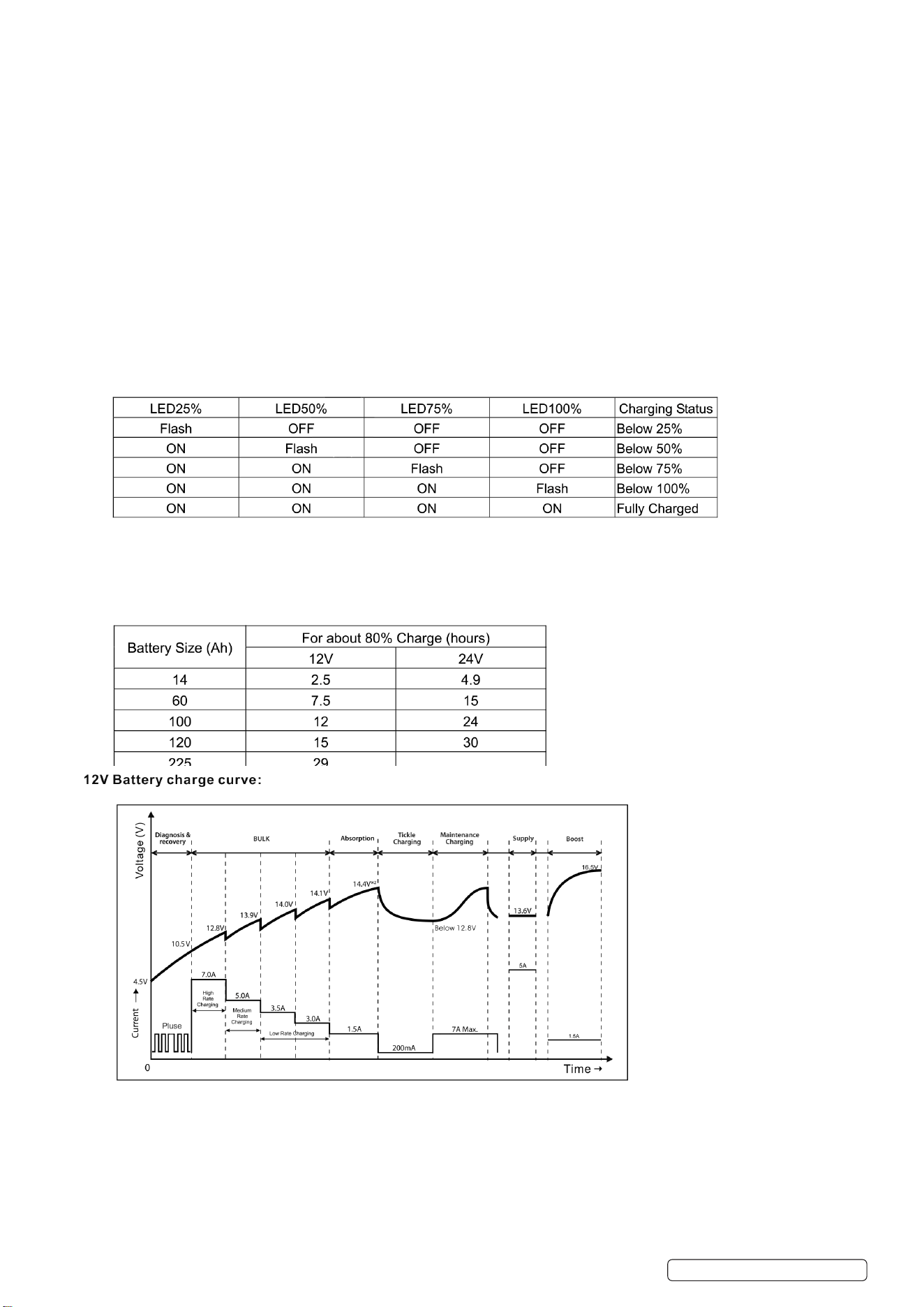
A. 12V BATTERY (10.5-14.6V±0.25V): power--->mode2--->mode3--->mode4 and then start the next cycle.
Every time the user presses down the button it will shift to the next mode and then execute it.
However, if a battery is not disconnected from the charger when fully charged, it will remain in the trickle charging mode even if the
user shifts the charging mode, which is useful for protecting the fully charged battery from damage. (NOTE: 13.6V Power Supply will
be selected by pressing mode button for 3 seconds.)
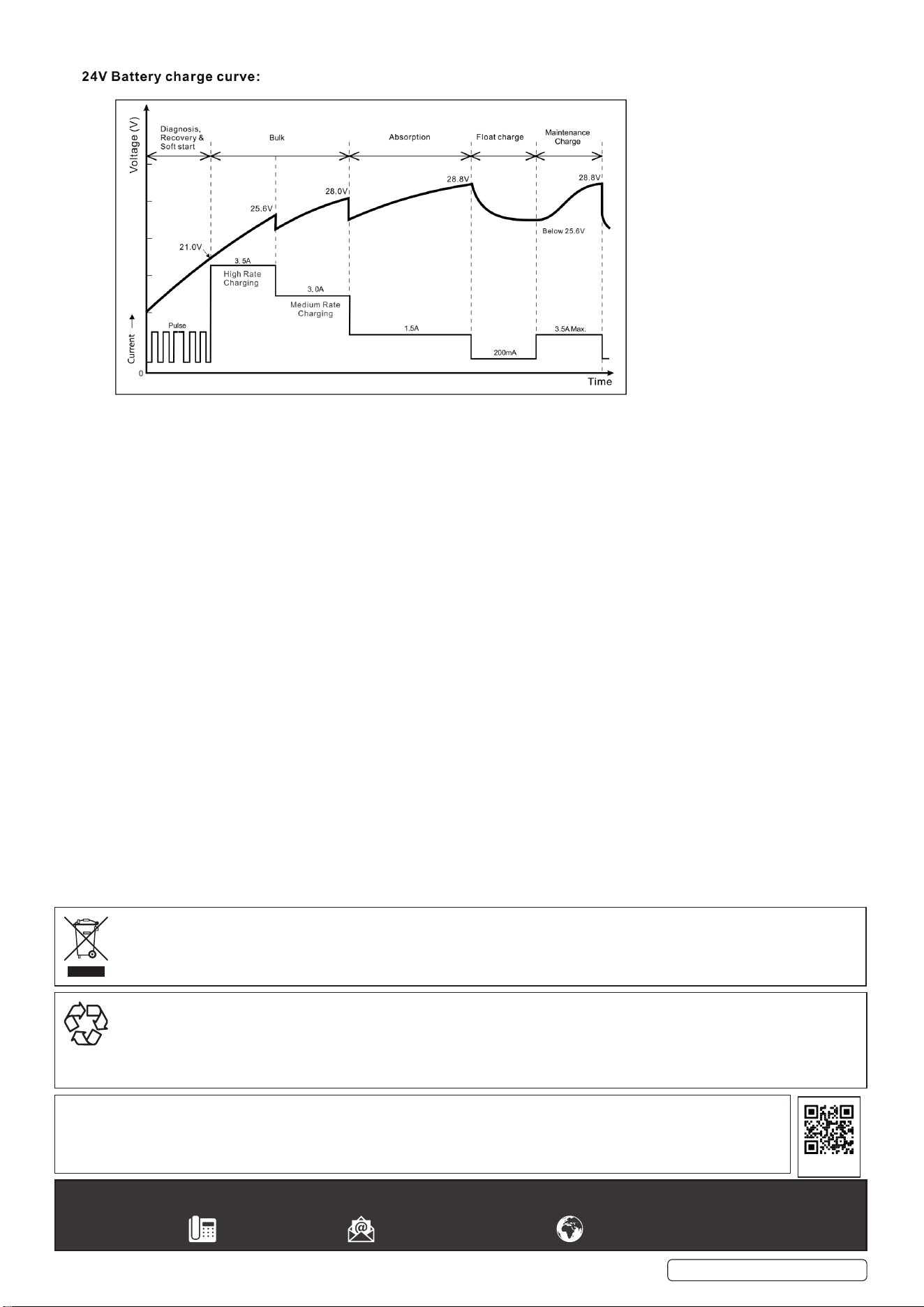
B. 24V BATTERY (21-30V±2%): power-,.mode1 and then start the next cycle. Every time the user presses down the button it will shift
to the next mode and then execute it. However, if a battery is not disconnected from the charger when fully charged, it will remain the
trickle charging mode even if the user shifts the charging mode, which is useful for protecting the fully charged battery from damage.
C. 14.6-21V±0.25V BATTERY (it may be a full-charged 12V battery or a deep discharged 24V battery):
Once the button is pressed down the charging LED will ash with the frequency of 2±0.2Hz. The embedded-in MCU will keep detecting
the trend of the battery voltage change automatically in the following 1-2 minutes. If battery voltage remains at the original value or
rises to a higher value, then it will be looked at as a 24V battery, otherwise as a 12V battery. Once this judgment is made the system
will adopt the corresponding action described in item a. or item b., and execute it until the battery is disconnected.
8.15. CHARGING STATUS INDICATION
8.16. MEMORY FUNCTION
8.16.1. This Smart Battery charger has a unique memory function (not included in 13.6V Supply and 16V boost mode). The charger returns to
last selected mode automatically when power is switched on. However, to charge various batteries at different ambient temperature a
specic charging mode could be selected manually by Pressing the MODE selection button until the light for correct voltage
indicates charging.
8.17. BULK CHARGING TIME
PRS6400 Issue 2 18/04/23
Original Language Version
© Jack Sealey Limited
Sealey Group, Kempson Way, Suffolk Business Park, Bury St Edmunds, Suffolk. IP32 7AR
01284 757500 sales@sealey.co.uk www.sealey.co.uk
ENVIRONMENT PROTECTION
Recycle unwanted materials instead of disposing of them as waste. All tools, accessories and packaging should be sorted, taken to
a recycling centre and disposed of in a manner which is compatible with the environment. When the product becomes completely
unserviceable and requires disposal, drain any fluids (if applicable) into approved containers and dispose of the product and fluids
according to local regulations.
Note: It is our policy to continually improve products and as such we reserve the right to alter data, specifications and component parts
without prior notice.
Important: No Liability is accepted for incorrect use of this product.
Warranty: Guarantee is 24 months from purchase date, proof of which is required for any claim.
WEEE REGULATIONS
Dispose of this product at the end of its working life in compliance with the EU Directive on Waste Electrical and Electronic Equipment
(WEEE). When the product is no longer required, it must be disposed of in an environmentally protective way. Contact your local solid
waste authority for recycling information.
REGISTER YOUR
PURCHASE HERE
8.18. ABNORMALITY PROTECTION FEATURE
8.18.1. If the charger is in bulk mode for more than 96 hours (105Ah cut-off) the charger will automatically turn off and turn on the ‘failure’ LED.
8.18.2. As with other failures, all other LEDs will ash on and off and no charge will be applied to the charger output. This feature prevents
damage if the battery is faulty.
PRS6400 Issue 2 18/04/23
Original Language Version
© Jack Sealey Limited