16232
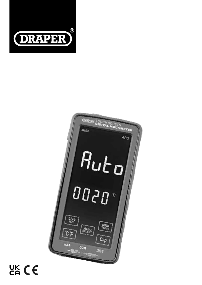
TOUCH SCREEN
DIGITAL
MULTIMETER
EN
Original Instructions
Version 1 – January 2024
1. Preface
These are the original product instructions. This
document is part of the product; retain it for the life of
the product, passing it on to subsequent holders.
Read this manual in full before attempting to
assemble, operate or maintain this product.
This Draper Tools manual describes the purpose
of the product and contains all the necessary
information to ensure its correct and safe use.
Following all the instructions and guidance in
this manual will ensure the safety of both the product
and the operator and increase the
lifespan of the product.
All photographs and drawings within this manual are
supplied by Draper Tools to help illustrate correct
operation of the product.
Every eort has been made to ensure the information
contained in this manual is accurate. However, Draper
Tools reserves the right to amend this document
without prior warning. Always use the latest version of
the product manual.
1.1 Product Reference
User Manual for: Touch Screen Digital Multimeter,
Stock No.: 16232
Part No.: DMM500
1.2 Revisions
Version 1: January 2024
First release
Please visit drapertools.com/manuals for the latest version
of this manual and the associated parts list, if applicable.
1.3 Understanding the Safety Content
of This Manual
WARNING! – Situations or actions that may result in
personal injury or death.
CAUTION! – Situations or actions that may result in
damage to the product or surroundings.
Important: – Information or instructions of particular
importance.
1.4 Copyright © Notice
Copyright © Draper Tools Limited.
Permission is granted to reproduce this manual for
personal and educational use ONLY. Commercial copying,
redistribution, hiring or lending is strictly prohibited.
No part of this manual may be stored in a retrieval system
or transmitted in any other form or means without written
permission from Draper Tools Limited.
In all cases, this copyright notice must remain intact.
2. Contents
1. Preface 2
1.1 Product Reference 2
1.2 Revisions 2
1.3 Understanding the Safety Content
of This Manual 2
1.4 Copyright © Notice 2
2. Contents 2
3. Product Introduction 3
3.1 Intended Use 3
3.2 Specication 3
4. Explanation of Symbols 4
5. Health and Safety Information 5
6. Identication and Unpacking 6 – 7
6.1 Product Overview 6
6.2 What’s in the Box? 7
6.3 Packaging 7
7. Operating Instructions 7 – 9
7.1 Charging the Multimeter 7
7.2 Operating the Multimeter 7 – 8
7.3 AC/ DC Voltage and Resistance Test
Measurements 8
7.4 AC/DC Current Measurement 8
7.5 Diode Testing 8
7.6 Capacitance Measurement 8
7.7 Temperature Measurement 8
7.8 Frequency 8
7.9 NCV Test Function 9
7.10 Live Circuit Recognition 9
7.11 Data Hold 9
7.12 Torch Feature 9
8. Product Care and Disposal 9
8.1 Maintenance and Storage 9
8.2 Disposal 9
9. Warranty 10
Notes 11
– 2 –

3. Product Introduction
3.1 Intended Use
This device is designed to measures current, resistance,
capacitance, frequency, temperature, diode and
non-contact voltage. It can also automatically identify and
measure AC/DC voltage and resistance.
Any other application beyond the conditions established
for use will be considered misuse. Draper Tools accepts no
responsibility for improper use of this product.
Read this manual in full before operating or maintaining
the product and retain it for later use.
3.2 Specication
Stock No.: 16232
Part No.: DMM500
Multimeter rating: CAT III, 600V
Dimensions: W 75 × H 150 × D 24 mm
Battery: 1 × 3.7V/2800mA USB-C Rechargeable
Weight: 220g
Circuit protection: Fuse
Overload protection: 250V DC or AC (RMS)
DC voltage:
Input resistance: 10MΩ
Input sensitivity: 0.8V
Maximum input voltage: 1000V
Measurement range: 0.001V to 1000V,
Accuracy: <60V = +/-(0.5% +3) >60V = +/-(0.8% +10)
Max Resolution: 0.001V
AC voltage:
Input resistance: 10MΩ
Input sensitivity: 0.8V
Maximum input current: 10A DC or AC RMS
Measurement range: 0.001V to 750V,
Accuracy: <60V = +/-(0.8% +3) >60V = +/-(1.0% +10)
Max Resolution: 0.001V
AC/DC current:
Overload protection: FF20A/250V fuse
Current Range: 1mA to 10A
(5A for 15 seconds maximum)
Accuracy: <6000mA = +/-(1.0% +5) >6000mA =
+/-(2.5% +10)
Max Resolution: 1mA
Resistance:
Measurement Range: 0.1Ω to 60MΩ
Accuracy: <600Ω = +/-(0.8% +3), 6MΩ = +/-(1.2% +3)
>6MΩ=+/-(2.5% +5)
Max Resolution: - 0.1Ω
Capacitance:
Measurement Range: 0.01nF to 100.0mF
Accuracy: <6.000mF = +/-(4.0% +20) 60.00mF =
+/-(5.0% +5) >60.00mF =For reference
Max Resolution: - 0.01nF
Frequency:
Measurement Range: 0.001Hz to 999.9kHz
Accuracy: +/-(0.8% +3)
Max Resolution: 0.001Hz
Diode check:
Test current Forward DC: 1mA typical
Test Current Reverse DC: 3.2V typical
Measurement range: 3.2VDC typical
Circuit On/O Test
Open circuit voltage: 1V typical
Temperature Test
Measurement Range:
( Excluding probes) -20 to +1000°C
-4 to +1832°F
Accuracy: 0.1 – 1°C/1°F
Operating conditions:
Operating temperature: 18–28°C
Storage Temperature 10 - 50°C
– 3 –
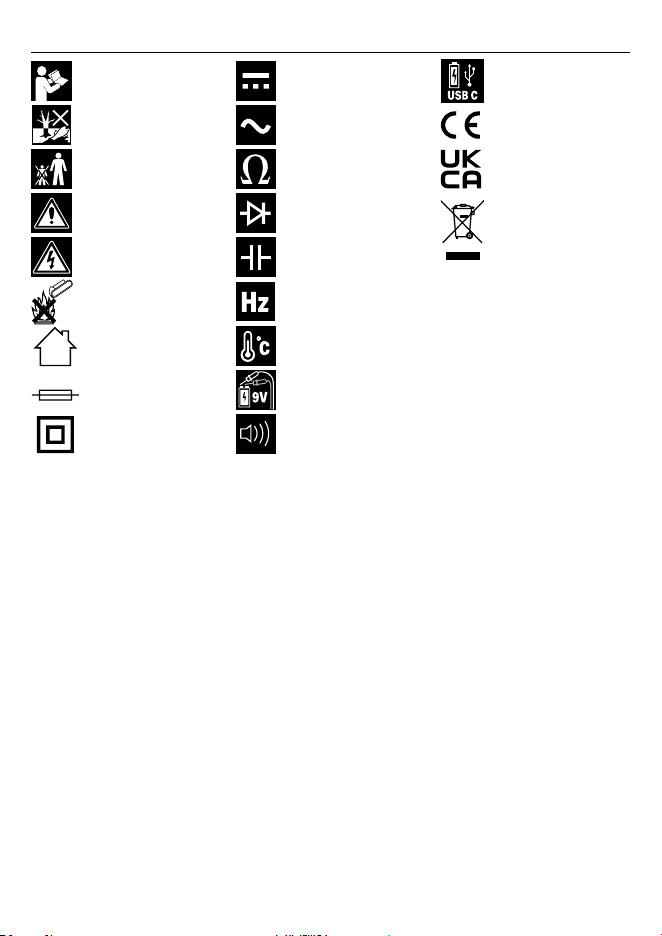
4. Explanation of Symbols
– 4 –
Read the instruction manual
Do not abandon in the
environment
Keep out of the reach of
children
Warning!
Warning! Risk of shock
Do not incinerate or throw
onto re
For indoor use only;
do not expose to rain
F200m A
Fuse protective device
Class II construction
(Double insulated)
Measures DC Voltage
Measures AC Voltage
Measures resistance
Measures diode forward
voltage drop
Measures capacitors
Measures frequency
Measures temperature
Measures battery voltage
up to 9V
Buzzer
USB C rechargeable battery
European conformity
UK Conformity Assessed
WEEE – Waste Electrical &
Electronic Equipment
Do not dispose of Waste
Electrical & Electronic
Equipment in with domestic
rubbish

5. Health and Safety Information
Important: Read all the Health and Safety instructions
before attempting to use this product. Non-compliance
may result in serious injury or death.
WARNING! Contact with live circuits can result in
severe electrical shock. When measuring voltage
above 30A, current above 10mA or AC power with
an inductive load:
− DO NOT enter voltages above 1000V DC or
750V AC (RMS).
− DO NOT apply voltages above 1000VAC or
750WAV between the common terminal and
Earth ground.
− DO NOT measure the current on a circuit when
the open circuit voltage and ground exceeds
250V.
− Discharge all high-voltage capacitors before
measuring capacitance.
• Take care not to touch the exposed contacts as they
may give a serious electric shock.
• ONLY trained and competent personnel may operate
this device.
• Use this product ONLY as instructed in this manual.
• This product is safe to use on three-phase distribution
circuits with overvoltage of up to 1,000V.
• Use ONLY accessories and spare parts supplied by
Draper Tools.
− DO NOT use any other leads with this product than
those supplied. Contact Draper Tools for
replacement options if the leads become damaged.
− DO NOT attempt to replace the rechargeable battery
as it is non-replaceable.
• Observe all standard precautions and good practice
when working with live electrical currents.
• Inspect the product for damage before every use,
particularly the contact tips.
− DO NOT use this product if the device or test leads
are damaged in any way.
− DO NOT operate this device with the casing open,
missing or damaged.
• Ensure that the device is clean, dry and free from grease
before use.
• Ensure that the correct function is selected before
switching on the device.
• DO NOT use this product if it is functioning abnormally.
Have it checked by a qualied and authorised
technician before next use.
– 5 –
• DO NOT exceed the maximum rated capacity per
function for this device as it may expose you to a shock
hazard.
• Ensure that the test lead contacts are disconnected from
the load or test circuit before selecting a function.
• DO NOT measure resistors, capacitors and diodes whilst
they are charged. Discharge fully before carrying out a
measurement.
• Assess any specic additional risks to the operator
before each use.
• DO NOT expose this product to excessive ambient
temperature, high humidity, ammable substances or
environments that produce a strong magnetic eld.
• DO NOT use this this product around explosive gases,
vapours or dust.
• DO NOT immerse this device in water or expose it to wet
conditions.
• ALWAYS wear protective insulated gloves while using
this product.
• ALWAYS keep your ngers behind the guards on the
test lead contact at all times during use.
• NEVER insert the test lead contacts into the device
terminals.
• DO NOT attempt to repair this device; it contains no
user-serviceable parts.
• Keep this product out of reach of children.
WARNING! ALWAYS ensure that the operator is
not in contact with the ground while taking
measurements, use insulating materials to prevent
the current from earthing.
– 6 –
(18)
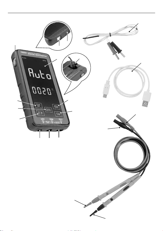
6.IdenticationandUnpacking
6.1 Product Overview
(5)
(2)
(3)
(4)
(1)
(10)
(9)
(8)
(6)
(13)
(12)
(11)
(7)
1. Power button
2. Torch & function indicator
3. NCV zone
4. LCD touch screen
5. USB charging port cover
6. Hold or Torch button
7. Capacity (CAP) button
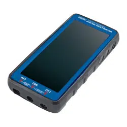
8. Voltage, resistance, circuit on/o,
frequency, temperature terminal
9. Common earth probe terminal
10. maA probe terminal
11. Temperature °C/°F button
12. Auto/ Function Select button
13. Live Non-Contact Voltage (NCV)
button
14. Negative (black) test lead
15. Negative contact tip cover
16. Positive (red) test lead
17. Positive contact tip cover
18. Temperature probe
19. USB C charging cable
(19)
(16)
(14)
(17)
(15)
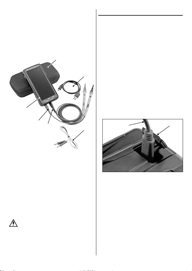
6.2 What’s in the Box?
Carefully remove the product from the packaging and
examine it for any signs of damage that may have occurred
during shipment.
Before assembling the product, lay the contents out and
check them against the parts listed below. If any part is
damaged or missing, do not attempt to use the product.
Please contact the Draper Helpline; contact details can be
found at the back of this manual.
A. 1 × Digital multimeter
B. 1 × Positive (red) test lead
C. 1 × Negative (black) test lead
D. 1 × Temperature probe
E. 1 × USB C charging cable
F. 1 × Carry case
Please visit drapertools.com for our full range of
accessories and consumables.
6.3 Packaging
Keep the product packaging for the duration of the
warranty period in case the product needs to be returned
for repair.
WARNING! Keep packaging materials out of reach
of children. Dispose of packaging correctly and
responsibly and in accordance with local
regulations.
7. Operating Instructions
Important: Before operating this product, read and
understand all the safety instructions listed in this manual.
Important: Inspect the device for signs of damage,
particularly the probes and and insulated test leads.
Replace faulty leads immediately.
For each measurement type, connect the negative test lead
(14) to the common earth probe terminal (9) and connect
the positive test lead (16) to either the voltage, resistance,
circuit on/o, frequency, temperature terminal (8) or
amperage probe terminal (10).
Remove the contact covers (15) and (17) before use.
If a negative value is shown on the display, check the
polarity of the test leads at the component contacts and
the device terminals.
7.1 Charging the Multimeter
Important: The rechargeable battery is not replaceable.
1.
Open the USB cover (5) and connect the USB cable (19).
Then connect the other end to a suitable USB power
outlet.
1 Fig.
(5)
(19)
3. The Torch indicator light (2) will be red when charging
and will turn green when fully charged.
4. Always charge when the low battery warning is
displayed.
7.2 Operating the Multimeter
1. To turn on the Multimeter, press and hold the POWER
button (1) for 3 seconds.
2. AUTO mode will be displayed on the screen. In this
mode AC/DC voltage and resistance are automatically
detected and measured.
3. To select the functions manually press the AUTO
SELECT button then scroll through until the required
mode is selected. Note: Always disconnect the test
leads when changing between functions.
– 7 –
(F)
(E)
(B)
(A)
(C)
(D)

– 8 –
• Automatic Power OFF – The Multimeter will
automatically switch o after 15 minutes if no operation
has occurred. There will be 5 beeps before it shuts down.
• Buzzer – will sound when switching on or any button is
pressed, or a function is selected. It will also sound if the
reading is over the specied range of the Multimeter.
7.3 AC/ DC Voltage and Resistance Test
Measurements
1. Use the AUTO mode or press the SELECT button (12) to
select the required measurement type.
2. Connect the negative test lead (14) to the common earth
probe terminal (9) and connect the Positive test lead (16)
to the voltage, resistance, circuit on/o, frequency,
temperature terminal (8).
3. Position the test lead contacts across the source of the
circuit to be measured, observing the correct polarity.
4. Enable the power to the circuit to be measured. The
voltage value is displayed on the LCD screen (4) along
with the voltage polarity if reversed.
Resistance
− If the resistance to be tested is part of a circuit,
switch the circuit o, disconnect the power and
allow all capacitors to discharge before
measurement.
WARNING! NEVER measure resistance
across a voltage source or on a powered
circuit.
− Touch the probe contacts at either side of the
resistance to be measured.
− The current value is displayed on the LCD screen (4).
7.4 AC/DC Current Measurement
1. Press the AUTO SELECT button (12) to select the
required measurement type.
2. Connect the negative test lead (14) to the common earth
probe terminal (9) and connect the Positive test lead (16)
to MaA terminal (10).
3. Open the circuit to be measured and connect the test
leads in series, using the correct polarity, to bridge the
gap.
4. Enable the power to the circuit to be measured. The
current value is displayed on the LCD screen (4).
Note: If the input exceeds 10A the display screen will show
‘OL’.
7.5 Diode Testing
1. Press the AUTO SELECT button (12) until the diode test
function
is selected.
2. Touch the test lead contacts against the contacts of the
diode, observing the correct polarity.
3. The approximate forward voltage drop of the diode is
displayed on the LCD screen (4); a typical diode
functioning normally will deliver a reading of 0.5–0.8V.
Note: If the polarity of the test probes is reversed the
display screen will show ‘OL’.
7.6 Capacitance Measurement
1. Press the CAP button (7) to select the capacitance test
function.
2. Connect the negative test lead (14) to the common earth
probe terminal (9) and connect the positive test lead
(16) to the voltage, resistance, circuit on/o, frequency,
temperature terminal (8).
3. Completely discharge the capacitor before connecting
the probes.
4. The current value is displayed on the LCD screen (4).
Note:
− When measuring large capacitance, it will take time
for the reading to stabilise.
− When measuring polar capacitors, pay attention to
the corresponding polarity to avoid damaging the
Multimeter.
7.7 Temperature Measurement
1. Press the °C°F button (11) to select the temperature
function and select between Celsius or Fahrenheit.
2 . To use the temperature probe (18) connect the negative
black test lead to the common earth probe terminal (9)
and connect the positive red test lead to the voltage,
resistance, circuit on/o, frequency, temperature
terminal (8).
3. The temperature will be displayed on the LCD screen (4).
Note: K-type thermocouples can measure up to a maximum
of 250°C.
7.8 Frequency
1. Press the AUTO SELECT button (12) until the frequency
(Hz) test function is selected.
2. Connect the negative test lead (14) to the common earth
probe terminal (9) and connect the positive test lead (16)
to the voltage, resistance, circuit on/o, frequency,
temperature terminal (8).
3. The current value is displayed on the LCD screen (4).
7.9 NCV Test Function
1. Press the LIVE NCV button (13) to select the
non-contact voltage test function. ‘EF’ will be displayed
on the screen.
2. Place the NCV zone (3) close to the live line of AC voltage
(less than 5mm).
− ‘- - L’ will be displayed and the indicator light (2) will
come on if the signal detected is weak.
− While the red indicator light is on ‘- - H’ will be
displayed and an alarm will sound when closer to the
AC voltage line.
7.10 Live Circuit Recognition
1. Press the LIVE NCV button (13) twice and connect the
positive test lead (16) to the voltage, resistance, circuit
on/o, frequency, temperature terminal (8). {Li uE} will
be displayed on the screen.
2. Once a reliable contact is made the display screen will
show ‘---H’ and the buzzer will sound.
7.11 Data Hold
When taking measurements to retain the reading on the
screen, press the HOLD/TORCH button (6) once to lock the
value. To unlock press the HOLD/TORCH button again.
7.12 Torch Feature
1. Press and hold the POWER button (1) for 3 seconds to
turn on the Multimeter.
2. Press the HOLD/TORCH (6) for 3 seconds to turn the
torch on. Press again to turn o the torch.
8. Product Care and Disposal
Important: Disconnect the test leads from the terminals
and any other source of voltage before performing any
maintenance on this product.
8.1 Maintenance and Storage
• Keep the product clean and free from dust, debris and
grease.
• Use a dry cloth ONLY to clean the housing of this device.
CAUTION! DO NOT use abrasives, solvents or
other aggressive chemicals as these may damage
plastic or insulated parts.
• Replace the test leads IMMEDIATELY if they are
damaged in any way or the conductors are exposed;
contact Draper Tools for replacement options.
• Important: Replacement test leads must be rated CAT III
1,000V.
• If the low battery indicator is shown on the display
charge the battery - , Refer to section 7.1 charging the
multimeter.
• Store the device in a cool, clean and dry environment,
out of direct sunlight and out of reach of children.
8.2 Disposal
For spare parts, servicing, and repair and replacement
options, please contact the Draper Tools Product Helpline
for details of your nearest authorised agent.
Draper Tools will endeavour to hold any spare parts, if
applicable, for seven years from the date that it sells the
nal matching stock item.
Any servicing or repairs carried out by unauthorised
personnel or installation of spare parts not supplied by
Draper Tools will invalidate your warranty.
At the end of its working life, dispose of the product
responsibly and in line with local regulations. Recycle
where possible.
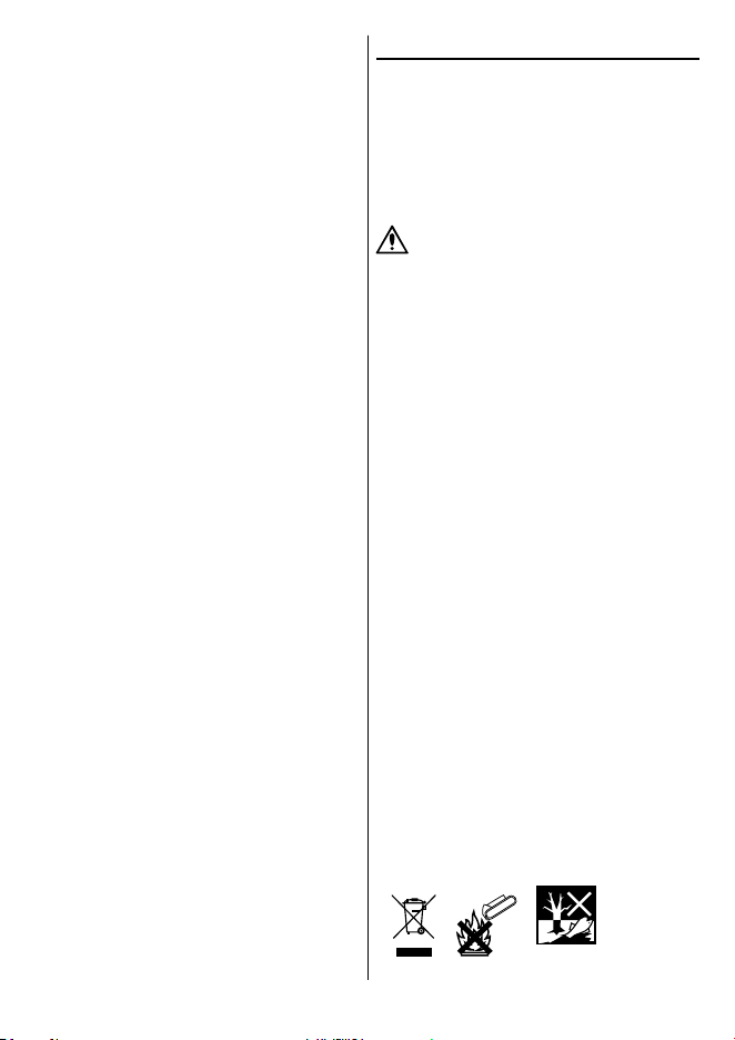
• DO NOT dispose of this product with domestic waste;
most local authorities provide appropriate recycling
facilities.
• DO NOT burn or mutilate batteries; this may release
toxic or corrosive substances.
• Dispose of batteries separately and in accordance with
local regulations.
– 9 –

9. Warranty
Draper Tools products are carefully tested and inspected
before shipment and are guaranteed to be free from
defective materials and workmanship.
Should the tool develop a fault, return the complete tool to
your nearest distributor or contact Draper Tools directly.
Contact information can be found at the back of this
manual.
Proof of purchase must be provided.
If, upon inspection, it is found that the fault occurring is
due to defective materials or workmanship, repairs will be
carried out free of charge. This warranty period covers
parts and labour for 12 months from the date of purchase.
Where tools have been hired out, the warranty period
covers 90 days from the date of purchase.
This warranty does not apply to any consumable parts,
batteries or normal wear and tear, nor does it cover any
damage caused by misuse, careless or unsafe handling,
alterations, accidents, or repairs attempted or made by any
personnel other than the authorised Draper Tools repair
agent.
In all cases, to make a claim for faulty workmanship or
materials within the standard warranty period, please
contact or return the product to the place of purchase.
Proof of purchase may be required.
If the place of purchase is no longer trading or if you
experience any diculties with your warranty, please
contact Customer Services with the product details and
your proof of purchase. Contact details can be found at the
back of this manual.
If the tool is not covered by the terms of this warranty,
repairs and carriage charges will be quoted and charged
accordingly.
This warranty supersedes any other guarantees expressed
or implied and variations of its terms are not authorised.
Your Draper Tools guarantee is not eective until you can
produce, upon request, a dated receipt or invoice to verify
your purchase within the guarantee period.
Please note that this warranty is an additional benet and
does not aect your statutory rights.
Draper Tools Limited
– 10 –

Notes
– 11 –

Contact Details
Draper Tools
Draper Tools Limited
Hursley Road
Chandler’s Ford
Eastleigh
Hampshire
SO53 1YF
UK
Website: drapertools.com
Email: [email protected]
Product Helpline: +44 (0) 23 8049 4344
Telephone Sales Desk: +44 (0) 23 8049 4333
General Enquiries: +44 (0) 23 8026 6355
General Fax: +44 (0) 23 8026 0784
Please contact the Draper Tools Product Helpline for repair and servicing enquiries.
© Published by Draper Tools Limited
Delta International
Delta International BV
Oude Graaf 8
6002 NL
Weert
Netherlands