02590
EN
Original Instructions
Version 1 - August 2024
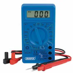
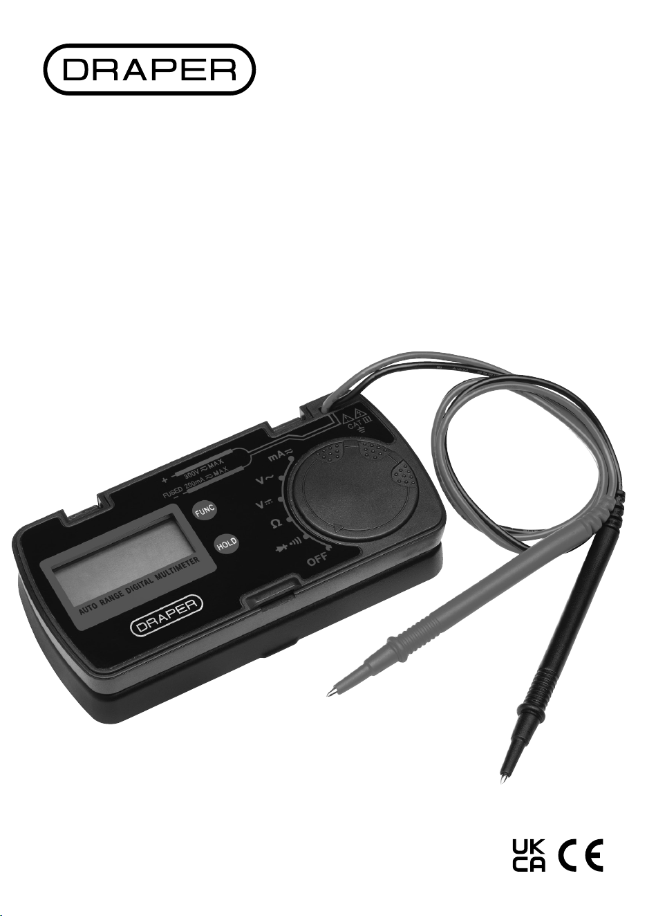
POCKE T
DIGITAL
MULTIMETER
1.1 Product Reference
User Manual for: Pocket Digital Multimeter
Stock No: 02590
Part No: DMM100
1.2 Revisions
Version 1: August 2024 – First release
Read this manual in full before using this product and
retain it for future use. Always use the latest version of
the manual. Please visit drapertools.com/manuals
for the latest version.
2. Intended Use
This compact meter is designed to measure AC/DC
voltage, AC/DC current, resistance, diode and continuity.
Any other application beyond the conditions established
for use will be considered misuse. Draper Tools accepts no
responsibility for improper use of this product.
2.1 Specication
1. Preface
– 2 –
EN
Stock No. 02590
Part No. DMM100
Multimeter Rating: CAT III, 300V
Dimensions: L 115 X W 56 x H 23mm
Batteries Required:
2 x LR44/1.5V button cell
(not supplied)
Fuse Protection: F250mAH 300V
Overload Protection: 300V DC/AC rms
Weight (approx.): 100g
IP Rating: IP20
Operating Temperature: 0°C to 40°C
Storage Temperature: -10°C to 50°C
Humidity: <85%
Range Selection Range Resolution Accuracy
DC Voltage
Input impedance: 10MΩ
200mV
2V
20V
200V
300V
0.1mV
0.001V
0.01V
0.1V
1V
+/- 0.8% reading +/-5 digits
+/- 1% reading +/-5 digits
AC Voltage
Input impedance: 10MΩ
Frequency range
40 – 400Hz
2V
20V
200V
300V
0.001V
0.01V
0.1V
1V
+/- 1% reading +/-5 digits
+/- 1.2% reading +/-5 digits
DC Current 20mA
200mA
0.01mA
0.1mA
+/- 1.2% reading +/-5 digits
AC Current
Frequency range 40 – 400Hz
20mA
200mA
0.01mA
0.1mA
+/- 1.5% reading +/-5 digits
Resistance 200Ω
2kΩ
20kΩ
200kΩ
2MΩ
20MΩ
0.1Ω
0.001kΩ
0.01kΩ
0.1kΩ
0.001MΩ
0.01MΩ
+/- 1.2% reading +/-5 digits
+/- 1% reading +/-5 digits
+/- 1.2% reading +/-5 digits
+/- 1.5% reading +/-5 digits
Diode Approx. forward voltage drop of the diode displayed.
Open circuit voltage about 1.5V
Continuity Open circuit voltage about 0.5V
The buzzer will sound if resistance is <30Ω and will not sound if >100Ω.

3. Health and Safety Information
– 3 –
EN
Important: Read all the Health and Safety instructions
before attempting to use this product. Failure to follow
these instructions may result in serious injury or death.
CAUTION! Contact with live circuits can result in
severe electrical shock.
− Take care not to touch the exposed contacts as
they may give a serious electric shock.
− Use caution when working with voltage above
60V DC, 30V AC RMS or 42V peak.
− DO NOT measure voltage above 300V DC or
AC (RMS).
− DO NOT apply voltages to the probe while
measuring current, diodes or continuity.
• ONLY trained and competent personnel may operate
this device.
• Use this product ONLY as instructed in this manual.
• ALWAYS connect the black test lead before
connecting the red test lead and disconnect the red
test lead rst.
• Use ONLY accessories and spare parts supplied by
Draper Tools.
− If the fuse must be replaced, use an identical item
with the same specication.
− If the battery must be replaced, use ones with the
same specication.
• Observe all standard precautions and good practice
when working with live electrical currents.
• Inspect the product for damage before every use,
particularly the contact tips.
• DO NOT use this product if the device, case or probe
leads are damaged in any way or if there is evidence of
battery leakage. Contact Draper Tools for
replacement options if the leads become damaged.
− If battery acid comes into contact with your skin,
wash it o immediately with plenty of clean water.
− If battery acid comes into contact with your eyes,
ush them with plenty of clean water and seek
immediate medical attention.
• Ensure that the device is clean, dry and free from
grease before use.
• Ensure that the function dial is in the correct position
before switching on the device.
• DO NOT use this product if it exhibits abnormal
behaviour and have it checked by a qualied and
authorised technician before next use.
• DO NOT exceed the maximum rated capacity per
function for this device as it may expose you to a
shock hazard.
• Ensure that the probe contacts are disconnected from
the load or test circuit before moving the function
dial.
• Assess any specic additional risks to the operator
before each use.
• DO NOT expose this product to excessive ambient
temperature, high humidity, ammable substances or
environments that produce a strong magnetic eld.
• DO NOT use this this product around explosive gases,
vapours or dust.
• DO NOT immerse this device in water or expose it to
wet conditions.
• ALWAYS wear protective insulated gloves while using
this product.
• Keep your ngers behind the guards on the test
probes during use.
• ALWAYS turn the function dial to the ‘OFF’ position
before opening the back panel to replace the batteries
or the fuse.
• DO NOT operate this device with the rear housing
open or missing and DO NOT use it if the rear housing
cannot be closed properly.
• DO NOT abuse, mutilate or burn the battery.
• Remove the batteries when the product is stored for
extended periods.
• DO NOT attempt to repair this device; it contains no
user-serviceable parts.
• Keep this product out of reach of children.
WARNING! ALWAYS ensure that the operator is
not in contact with the ground while taking
measurements, using insulating materials to
prevent the current from earthing.
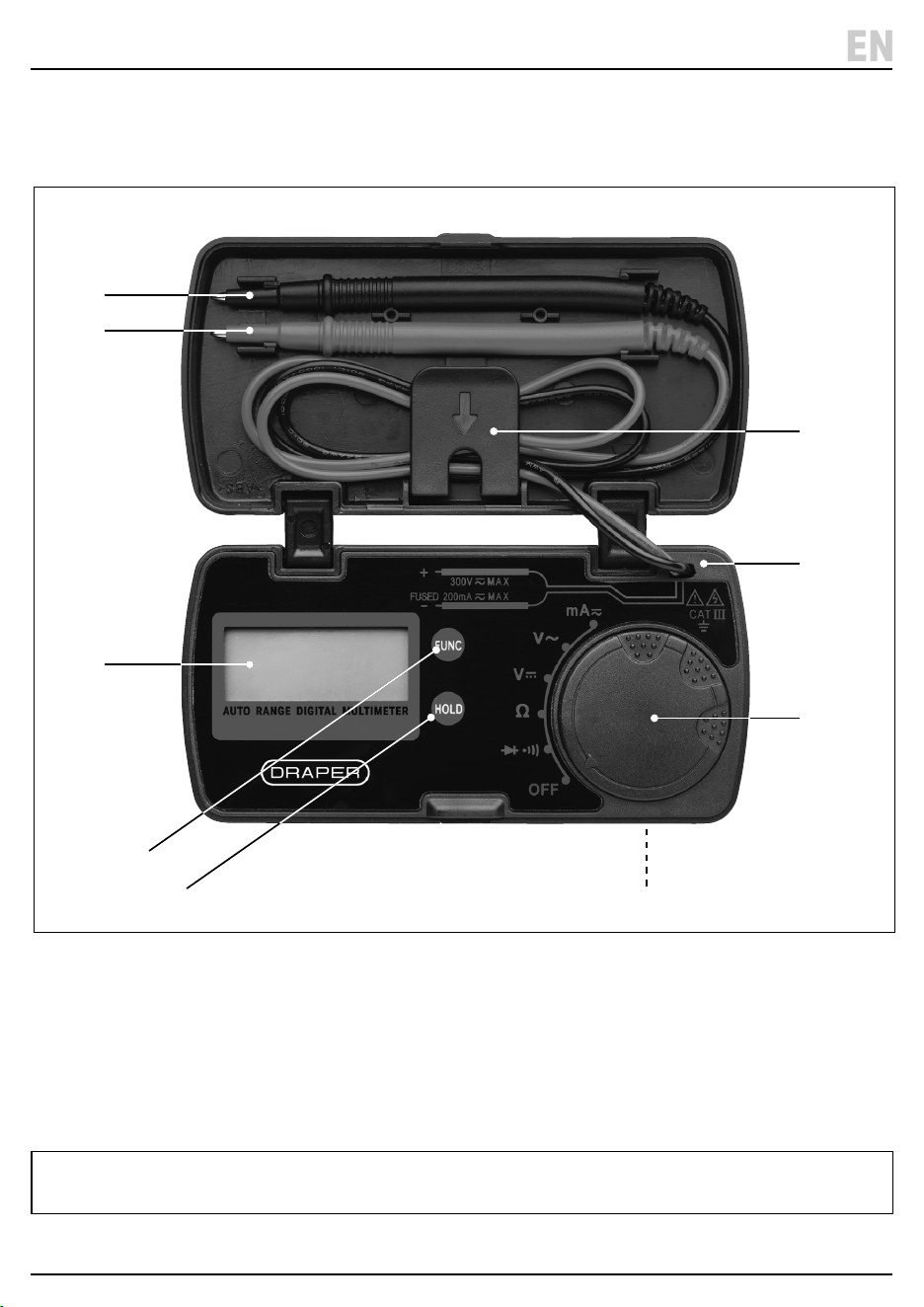
4. Identication and Unpacking
– 4 –
EN
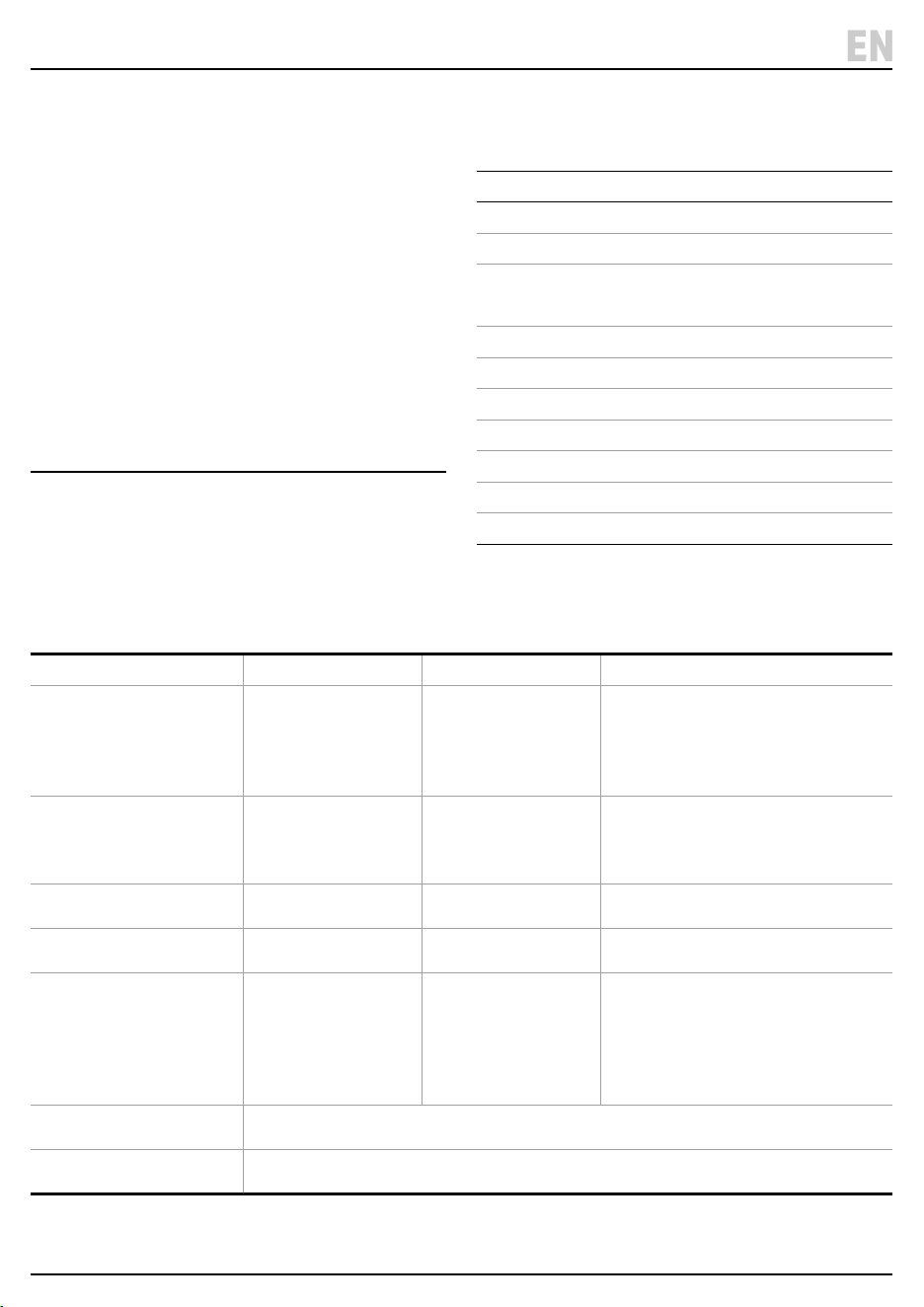
1. Display screen
2. ‘FUNC’ Function button
3. ‘HOLD’ button
4. Function select dial
5. Storage case
6. Lead retainer clip
7. Negative (black) test lead and probe
8. Positive (red) test lead and probe
9. Back cover (battery/fuse compartment)
Carefully remove the product from the packaging and
examine it for any signs of damage that may have
occurred during shipment.
If any part is damaged or missing, do not attempt to use
the product. Please contact the Draper Helpline; contact
details can be found at the back of this manual.
(7)
(8)
(2)
(3)
(9)
(5)
(6)
(4)
(1)
Please visit drapertools.com for our full range of accessories and consumables.
5. Operating Instructions
– 5 –
EN
Important: Before operating this product, read and
understand all the safety instructions listed in this
manual.
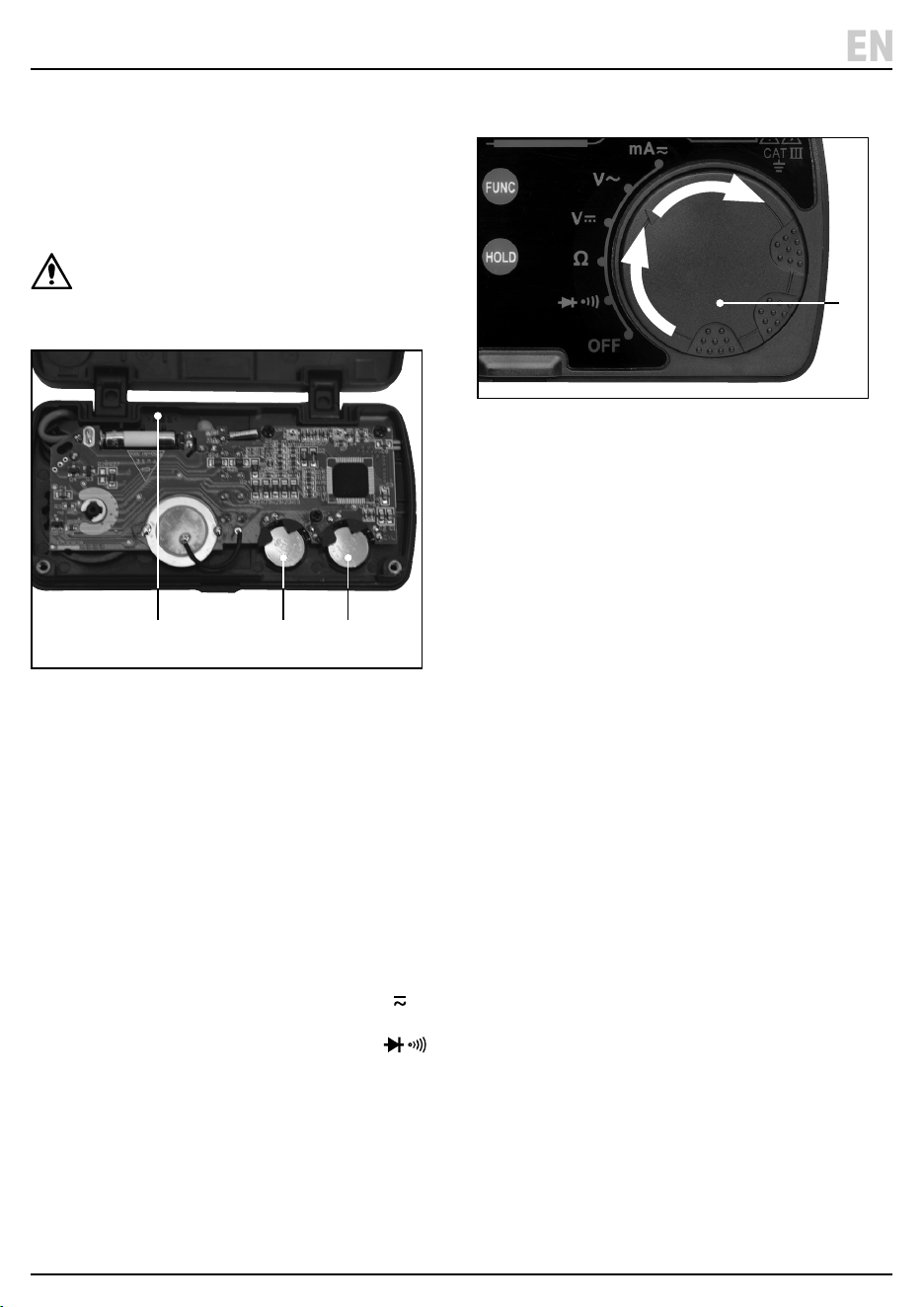
5.1 Installing/Replacing the Battery
Important: Use ONLY LR44 batteries.
WARNING! Remove the test leads from the
circuit under test and turn the function dial to
the ‘OFF’ position before opening the back
cover.
Fig. 1
1. Unscrew and lift the back cover o.
2. Fit two LR44 batteries (A) – ensuring polarity
connections are correct (follow the indicators on the
battery compartment).
3. Ret and screw the back cover on and tighten
securely.
5.2 Function Button ‘FUNC’ (2)
• Turn the function select dial (4) to the required
measurement mode. Then press the function button
(2) to switch between;
− AC and DC current measurement when mA
mode selected.
− Continuity and diode test functions when
mode selected.
5.3 Data ‘HOLD’ Button (3)
• Press to retain the measured value on the screen.
• ‘HOLD’ will appear on the screen when the data hold
mode is selected.
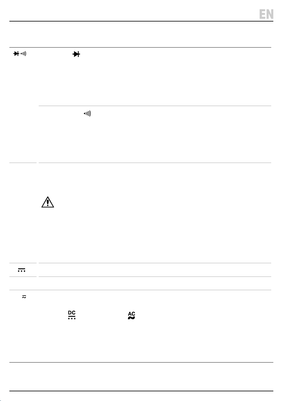
5.4 Function Select Dial (4)
Fig. 2
• Turn the function select dial (4) to select the required
measurement mode.
• Always return the dial to the ‘OFF’ position after
testing.
5.5 Auto Power O
• The meter will automatically go into sleep mode if the
meter has not been operated for 15 minutes.
• Turn the function dial or press any button to turn the
meter back on.
• Note: If the ‘HOLD’ button is pressed while in sleep
mode the auto power o function will be disabled.
(A)(B) (A)
(4)
– 6 –
EN
5. Operating Instructions
Dial
Position
Function Mode
Diode Mode
1. Press the function button (2) to select the diode function.
2. Touch the probe contacts against the contacts of the diode, observing the correct polarity.
3. The approximate forward voltage drop of the diode is displayed on the screen (1); a typical diode
functioning normally will deliver a reading of 0.5–0.7.
• If the connection is reversed ‘OL’ will be displayed.
Continuity Mode
1. Press the function button (2) to select the continuity function.
2. Connect the test leads across the circuit to be tested.
3. If the resistance is less than about 30Ω, the buzzer will sound.
Note: Before testing, disconnect all power to the circuit to be tested and discharge all capacitors
thoroughly.
Ω
Resistance Mode
• If the resistance to be tested is part of a circuit, switch the circuit o, disconnect the power and
allow all capacitors to discharge before measurement.
WARNING! NEVER measure resistance across a
voltage source or on a powered circuit.
• Touch the probe contacts at either side of the resistance to be measured. The current value is
displayed on the screen (1).
Note:
− For resistance measurements > 1M, the reading may take a few seconds to stabilise. This is
normal.
− When the test leads are in open circuit state ‘OL’ will be displayed to indicate over range.
V
DC Voltage mode
V ~
AC Voltage mode
mA AC/DC Current mode
Use the function button to switch between AC and DC
DC Current on screen. AC Current on screen.
1. Turn o power to the circuit to be tested. Then discharge all capacitors.
2. Break the circuit path to be tested, then connect the test leads in series with the circuit.
3. Turn on power to the circuit, then read the display.
4. For DC current measurements, the polarity of the red test lead connection will be indicated as well.
– 7 –
EN
Important: Disconnect the probes from any source of
voltage and turn the Multimeter o before performing
any maintenance on this product. DO NOT attempt to
repair or service the meter unless qualied to do so.
6.1 Maintenance and Storage
• Keep the product clean and free from dust, debris and
grease.
• Use a dry cloth ONLY to clean the housing of this
device.
CAUTION! DO NOT use abrasives, solvents or
other aggressive chemicals as these may
damage plastic or insulated parts.
• If the low battery indicator ( ) is shown on the
display, replace the battery as soon as possible; see
5.1 Installing the Battery.
• If the fuse (B) must be replaced, follow section
5.1 battery installation, remove the fuse from its
holder and install an equivalent fuse its place.
• Important: This product requires a F200mA/250V
fast fuse.
• Remove the batteries when storing the device for
extended periods.
• Store the device in a cool, clean and dry environment,
out of direct sunlight and out of reach of children.
1.2 Disposal
At the end of its working life, dispose of the product
responsibly and in line with local regulations. Recycle
where possible.
• DO NOT dispose of this product with
domestic waste; most local authorities
provide appropriate recycling facilities.
• DO NOT burn or mutilate batteries; this may
release toxic or corrosive substances.
• Dispose of batteries separately and in
accordance with local regulations.
7. Warranty
• Warranty period is 12 months from the date of
purchase.
• Visit drapertools.com/warranty for full details.
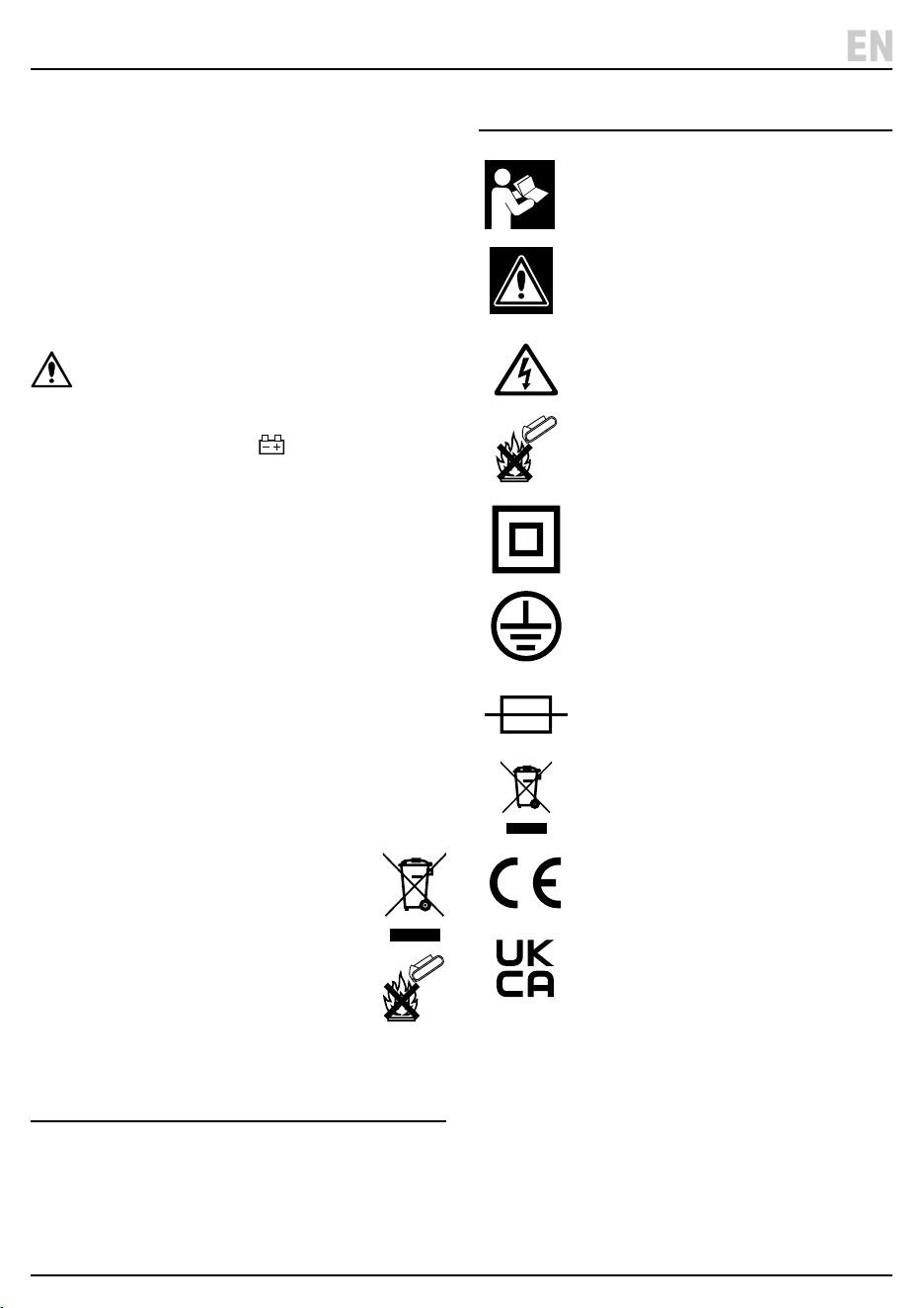
8. Explanation of Symbols
6. Product Care and Disposal
Read the instruction manual
Warning!
Danger! High voltage/current
Do not incinerate or throw onto re
Class II construction
(Double insulated)
Earthed
Fuse
WEEE – Waste Electrical &
Electronic Equipment
Do not dispose of Waste Electrical & Electronic
Equipment in with domestic rubbish
European conformity
UK Conformity Assessed

© Published by Draper Tools Limited© Published by Draper Tools Limited
Delta International
Delta International BV
Oude Graaf 8
6002 NL
Weert
Netherlands
Contact Details
Draper Tools
Draper Tools Limited
Hursley Road
Chandler’s Ford
Eastleigh
Hampshire
SO53 1YF
UK
Website: drapertools.com
Email: [email protected]
Product Helpline: +44 (0) 23 8049 4344
Telephone Sales Desk: +44 (0) 23 8049 4333
General Enquiries: +44 (0) 23 8026 6355
Please contact the Draper Tools Product Helpline for repair and servicing enquiries.