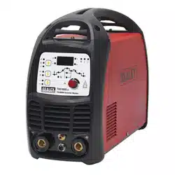
200A TIG/MMA HF AC/DC INVERTER WELDER
230V
MODEL NO: TIG200HFACDC.V2
Thank you for purchasing a Sealey product. Manufactured to a high standard, this product will, if used according to these
instructions, and properly maintained, give you years of trouble free performance.
IMPORTANT: PLEASE READ THESE INSTRUCTIONS CAREFULLY. NOTE THE SAFE OPERATIONAL REQUIREMENTS, WARNINGS & CAUTIONS. USE
THE PRODUCT CORRECTLY AND WITH CARE FOR THE PURPOSE FOR WHICH IT IS INTENDED. FAILURE TO DO SO MAY CAUSE DAMAGE AND/OR
PERSONAL INJURY AND WILL INVALIDATE THE WARRANTY. KEEP THESE INSTRUCTIONS SAFE FOR FUTURE USE.
1. SAFETY
1.1. ELECTRICAL SAFETY
WARNING! It is the owner’s responsibility to read, understand and comply with the following:
You must check all electrical equipment and appliances to ensure that they are safe before use. You must inspect power supply leads,
plugs and all electrical connections for wear and damage. You must ensure the risk of electric shock is minimised by the installation of
appropriate safety devices. An RCCB (Residual Current Circuit Breaker) should be incorporated in the main distribution board. We
also recommend that an RCD (Residual Current Device) is used with all electrical products. It is particularly important to use
an RCD with portable products that are plugged into an electrical supply not protected by an RCCB. If in doubt consult a
qualified electrician.
You must also read and understand the following instructions concerning electrical safety.
1.1.1. The Electricity At Work Act 1989 requires all portable electrical appliances, if used on business premises, to be tested by a
qualiedelectrician,usingaPortableApplianceTester(PAT),atleastonceayear.
1.1.2. The Health & Safety at Work Act 1974 makes owners of electrical appliances responsible for the safe condition of the appliance
and the safety of the appliance operator. If in any doubt about electrical safety, contact a qualified electrician.
Ensure the insulation on all cables and the product itself is safe before connecting to the mains power supply.
See1.1.1.&1.1.2.aboveanduseaPortableApplianceTester(PAT).
Ensure that cables are always protected against short circuit and overload.
Regularly inspect power supply, leads, plugs for wear and damage and all electrical connections
to ensure that none is loose.
Important: Ensure the voltage marked on the product is the same as the electrical power supply
to be used and check that supply is correctly fused, see fuse rating at right.
8 DO NOT pull or carry the powered appliance by its power supply lead.
8 DO NOT pull power plugs from sockets by the power cable.
8 DO NOT use worn or damaged leads, plugs or connections. Immediately replace or have
repaired by a qualified electrician.
This product comes without a plug. You must contact a qualified electrician to ensure an
adequate supply is available.
If fitting such a plug -
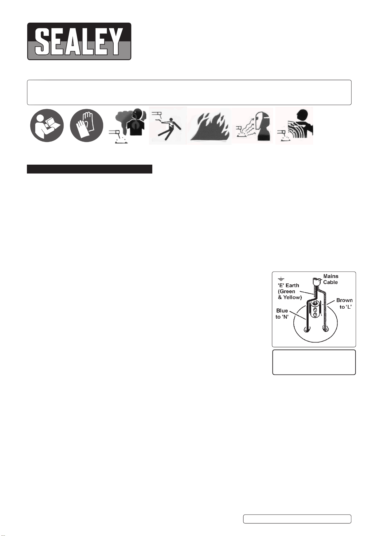
Ensure that the unit is correctly wired and earthed, as follows:
a) Connect the GREEN/YELLOW earth wire to the earth terminal ‘E’.
b) Connect the BROWN live wire to live terminal ‘L’.
c) Connect the BLUE neutral wire to the neutral terminal ‘N’.
d) After wiring, check there are no bare wires, that all wires have been correctly connected, that the cable outer insulation is
clamped by the cable grip and that the grip is tight.
WARNING! The welder may produce voltage surges in the mains supply which can damage other sensitive equipment
(e.g. computers). To prevent this happening, it is recommended that the welder is connected to a power supply that does not
feed any sensitive equipment.
To achieve maximum output this welder will require a 32A fused supply. We recommend you discuss the installation of
an industrial round pin plug and socket with a competent electrician.
WARNING! Be very cautious if using a generator to power the welding set. The generator must be self-regulating and stable with
regard to voltage, wave form and frequency. The output must be greater than the power consumption of the welding set.
If any of the requirements are not met the electronics within the welding set may be affected.
NOTE: The use of an unregulated generator may be dangerous and will invalidate the warranty on the welding set.
WARNING! The welding set may produce voltage surges in the mains supply which can damage other sensitive equipment
(e.g. computers). To prevent this happening, it is recommended that the welding set is connected to a power supply that
does not feed any sensitive equipment.
1.2. GENERAL SAFETY
▲ DANGER! Unplug the inverter from the mains power supply before connecting or disconnecting cables or performing maintenance or
service. Direct contact with the inverter circuit is dangerous.
9 Keep the inverter and cables in good working order and condition. (Take immediate action to repair or replace damaged parts).
9 Use genuine parts and accessories only. (Non recommended parts may be dangerous and will invalidate the warranty).
THIS PRODUCT REQUIRES A
MINIMUM 32 AMP
SUPPLY
TIG200HFACDC.V2 Issue 3 (1) 31/01/2023
Original Language Version
© Jack Sealey Limited
Refer to
instructions
Wear protective
gloves
Warning:
Fumes & Gases
Warning:
Electric Shock
Warning:
Fire Risk
Warning:
Arc Rays
Warning:
Magnetic Fields
9 Locate inverter in an adequate working area for its function. Ensure area has adequate ventilation as welding fumes are harmful.
WARNING! If it is necessary for you to assemble the work clamp cable, ensure that sufficient copper strands are exposed and
turned back to make full contact within the dinse plug to ensure a good electrical contact. Loose connection will cause overheating,
rapid deterioration and loss in efficiency.
9 Ensure there is no obstruction to the flow of clean cool air through the ventilation apertures and ensure there are no conductive dusts,
corrosive vapours or humidity which could enter the inverter and cause serious damage.
9 Keep working area clean and tidy and free from unrelated materials. Also ensure the working area has adequate lighting.
WARNING! Use welding head shield to protect eyes and avoid exposing skin to ultraviolet rays given off by electric arc. Wear safety
welding gauntlets.
9 Remove ill fitting clothing, remove ties, watches, rings, and other loose jewellery, and contain long hair.
9 Ensure the workpiece is correctly secured before operating the inverter.
9 Avoid unintentional contact with workpiece. Accidental or uncontrolled switching on of the torch may be dangerous and will cause the
nozzle to wear.
9 Keep unauthorised persons away from the working area, and any persons working within the area must wear the same protective
items as the user.
9 Operators must receive adequate training before using the inverter. The inverter must only be operated under supervision.
9 Stand correctly keeping a good footing and balance, ensure the floor is not slippery, and wear non-slip shoes.
WARNING! When unit is switched off wait for 15 seconds whilst capacitors discharge before opening the case.
9 Turn voltage switch to “0” (off) when not in use.
8 DO NOT operate the inverter if it or its cables are damaged.
8 DO NOT use welding cables over 10m in length. (Cables should be as short as possible).
8 DO NOT attempt to fit any non genuine torches, components, or parts to the inverter unit. To do so may cause damage and will
invalidate the warranty.
8 DO NOT use any metallic structure which is not part of the work piece as a substitute for the return cable. This may jeopardise results
and may be dangerous. Exception: Metallic work bench, but connect as near to weld as possible.
8 DO NOT hit the electrode on the workpiece, this may damage the electrode and make strike-up difficult.
8 DO NOT get inverter wet or use in damp or wet locations or areas where there is condensation.
▲ DANGER! DO NOT weld near inflammable materials, solids, liquids, or gases.
8 DO NOT weld containers or pipes which have held flammable materials or gases, liquids or solids. Avoid operating on materials
cleaned with chlorinated solvents or near such solvents.
8 DO NOT pull the inverter by the cable, or the torch, and DO NOT bend or strain cables, protect from sharp or abrasive items, and DO
NOTstandoncablesorleads.Protectfromheat.Longlengthsofslackmustbegathered&neatlycoiled.DO NOT place cables
where they may endanger
8 DO NOT touch the workpiece close to the weld as it will be very hot. Allow to cool.
8 DO NOT touch the torch immediately after use. Allow the torch to cool.
8 DO NOT operate inverter while under the influence of drugs, alcohol or intoxicating medication, or if fatigued.
9 When not in use store the inverter in a safe, dry, childproof area.
2. INTRODUCTION
Fan-cooled AC/DC power supply for pulse TIG and MMA welding applications. Suitable for welding aluminium, magnesium, stainless steel,
steel, copper, nickel and titanium. TIG cycle includes post gas and current down-slope regulation. Features regulated high frequency (HF)
push-button arc that prevents having to touch the workpiece to start, keeping the tip in good condition for longer. Includes connector for foot
pedal when more control is required.
3. SPECIFICATION
Model No: .............................................. TIG200HFACDC.V2
Power Output: ...........................................................10-200A
Duty Cycle: ................................ 100% @ 77A, 15% @ 200A
Electrode Capacity: ............................................... Ø1.6-4mm
AbsorbedPower: ............................................................8kW
Supply: ......................................................................... 230V*
4. OPERATION
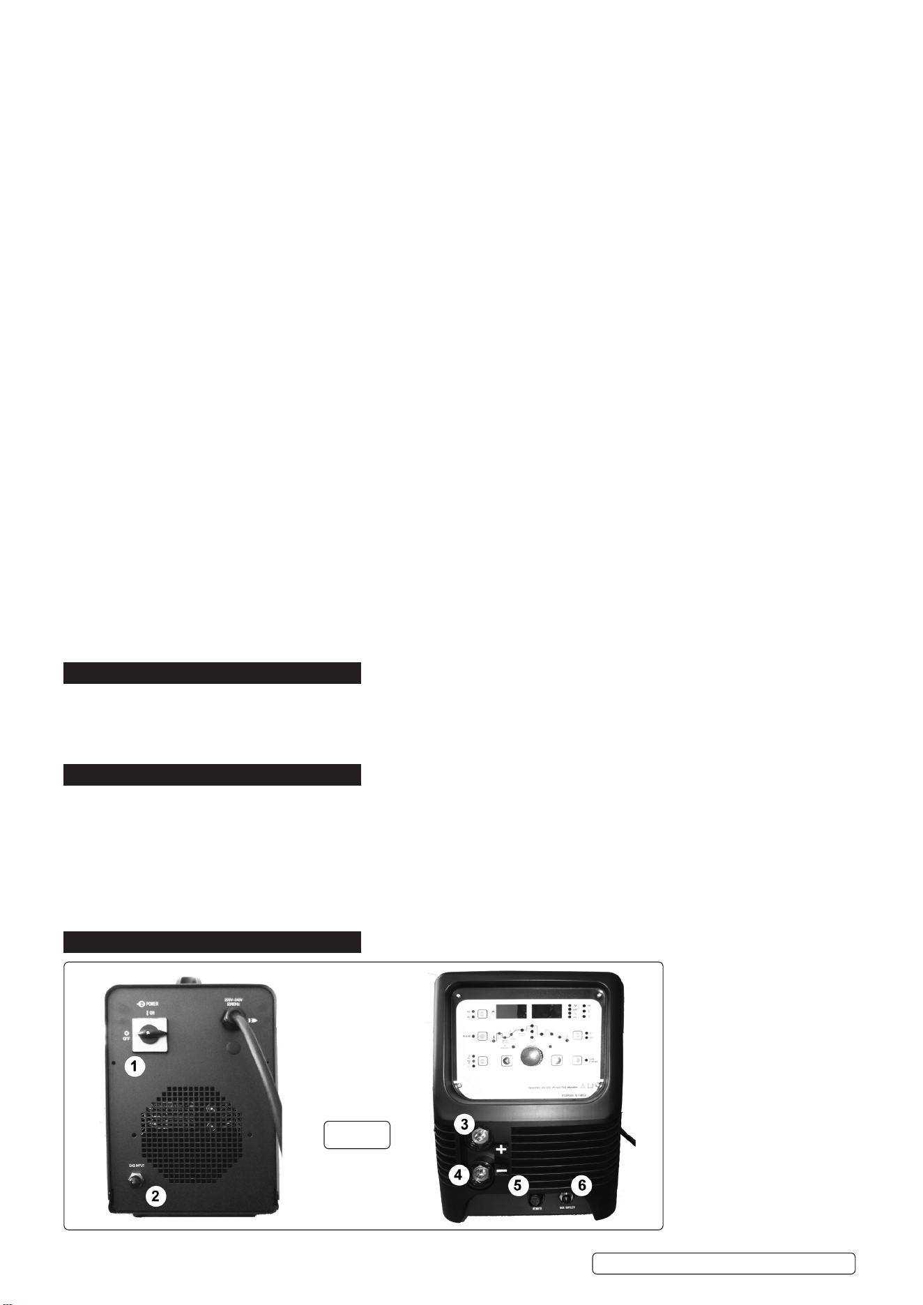
Key to fig.1
1: On/Off Switch
2: Gas Inlet
3:PositiveConnection
4: Negative Connection
5: Control Connection
6: Gas Outlet
g.1
Original Language Version
© Jack Sealey Limited
Insulation Class:.................................................................. H
Protection: .................................................................... IP21S
Accessories: ..........................................................................
Electrode Holder (Optional): .......................................MMA01
FootPedal(Optional): ............................... TIG200HFACDCF
Note: *to achieve maximum power a 32A supply may be required.
TIG200HFACDC.V2 Issue 3 (1) 31/01/2023
4.1. LEAD CONNECTION
MMAMode:ConnecttheelectrodeholdertothePositive(+)connector(fig.1.3)andtheearthleadtotheNegative(-)connector(fig.1.4).
TIGMode:ConnecttheearthclamptothePositive(+)connectorandtheTIGtorchtothenegative(-)connector.
4.2. GAS CONNECTION
4.2.1. Using the clear tubing supplied connect the regulator to the gas inlet on the back of the inverter (fig.1.2) and gas outlet on the front
(fig.1.6). Secure the tubing on each connector by using the worm drive clamps supplied.
4.2.2. Open the regulator before opening the cylinder valve. Test for leaks.
4.2.3. Set the gas flow to suit the welding parameters required.
4.2.4. If necessary the gas flow can be adjusted during welding using the regulator knob.
4.3. CONTROL CONNECTION
4.3.1. Ifusingthetorchtrigger,connectthecontrolplugfromtheleadassemblyintothecontrolconnection(g.1.5).
4.3.2. OPTIONALPEDALCURRENTCONTROL(TIG200HFACDCF). Connect the plug from the control pedal to the control connector
(g.1.5),Leavetheleadfromtheleadassemblyhangingloose.
4.4. MMA: DC STICK ARC WELDING
4.4.1. UsingtheUpandDownkeys,settheweldingmodeselector(g.2.9) to, the welding current may be adjusted by means of the
adjustmentknob(g.2.1).
4.4.2. Thehotstartcurrent(g.3.2)andarcforcecurrentonly(g.3.13)canbeadjustedinthismodetomatchthematerialbeingwelded.
Toselecttheparameterusetheparameterselectors(gs.2.10&2.11)tocyclebetweenfunctions.Thevaluemaybeadjustedusing
theadjustmentknob(g.2.1).
4.5. DC TIG WELDING
4.5.1. UsingtheUpandDownkeys,settheweldingmodeselector(g.2.9)to for high frequency start or for lift start.
4.5.2. SwitchtheAC/DCselector(g.2.5)toDC.
4.5.3. Thepre-owtime(g.3.1),weldingcurrent(g.3.5)andgasdelaytimeindicator(g.3.12)maybeadjustedinthismode.
4.5.4. Toselecttheparameterusetheparameterselectors(gs.2.10&2.11)tocyclebetweenfunctions.Thevaluemaybeadjustedusing
theadjustmentknob(g.2.1).
4.5.5. 2or4touchtriggercontrolmaybeselectedbyusingthetriggermodeselector(g.2.8).
2 touch allows the power to be applied whilst the trigger is pressed.
4 touch latches the trigger until the pressed for a second time.
The 4 touch mode is useful for long runs of weld, saving operator fatigue and allowing a steadier weld. In this mode the power will be
applied until the selected down slope time has elapsed
4.6. DC PULSE TIG WELDING
4.6.1. UsingtheUpandDownkeys,settheweldingmodeselector(g.2.9)to for high frequency start or for lift start.
4.6.2. SwitchtheAC/DCselectorto(g.2.5)DC.
4.6.3. Thepre-owtime(g.3.1),pulsepeakcurrent(g.3.6),pulsewidth(g.3.7),pulsefrequency(g.3.8),pulsebackgroundcurrent
(g.3.9)andgasdelaytime(g.3.12)mayallbeadjustedinthismode.
4.6.4. Toselecttheparameterusetheparameterselectors(gs.2.10&2.11)tocyclebetweenfunctions.Thevaluemaybeadjustedusing
theadjustmentknob(g.2.1).
4.7. AC TIG WELDING
4.7.1. UsingtheUpandDownkeys,settheweldingmodeselector(g.2.9)to for high frequency start or for lift start.
4.7.2. SwitchtheAC/DCselector(g.2.5.)toAC.
Original Language Version
© Jack Sealey Limited
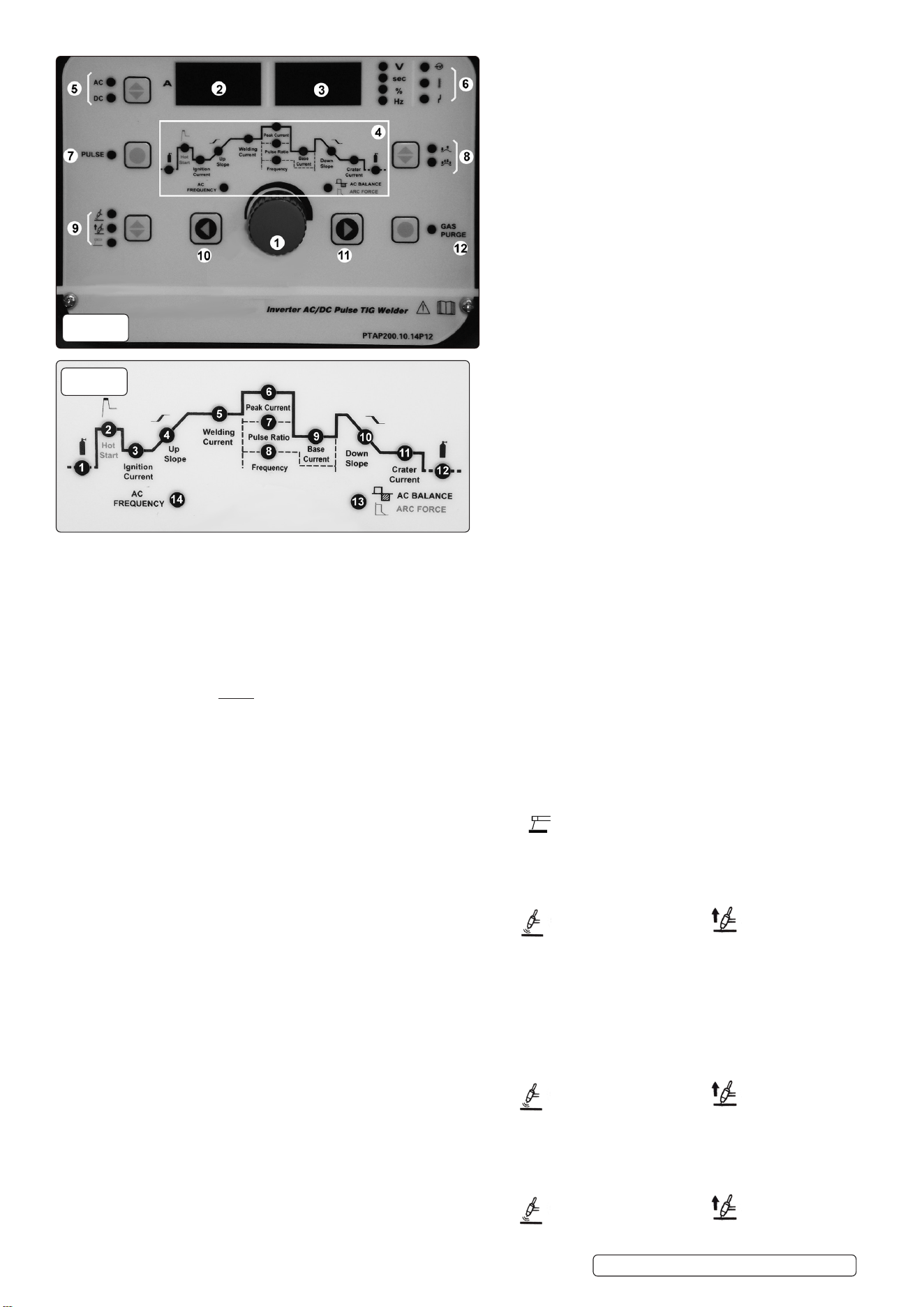
Key to fig.3
1:Pre-flowtimeindicator
2: Hot Start Current Indicator (MMA)
3: Arc Starting Current Indicator (4T)
4: Uphill Time Indicator (4T)
5: Welding Current Indicator (CC)
6:PeakCurrentIndicator(Pulse)
7:PulseWidthIndicator(Pulse)
8:PulseFrequencyIndicator(Pulse)
9:BackgroundCurrentIndicator(Pulse)
10: Minus Grade Time Indicator (4T)
11: Arc Stopping Current Indicator (4T)
12: Gas Delay Time Indicator
13: Clear Area Width (ACTIG) / Arc Force (MMA)
14: AC Frequency (ACTIG)
Key to fig.2
1: Adjustment Knob
2: Current Display
3: Voltage Display
4:ProcedureParameters
(see fig.3)
5: AC/DC Selector
6: Status Indicator
7:PulseSelector
8: Trigger Mode Selector
9:WeldingModeSelector
10:Parameter Minus Selector
11:ParameterPlusSelector
12: Gas Check Selector
g.2
g.3
TIG200HFACDC.V2 Issue 3 (1) 31/01/2023
4.7.3. Thepre-owtime(g.3.1),weldingcurrent(g.3.5),gasdelaytime(g.3.12),clearareawidth(g.3.13)andACfrequency(g.3.14)
may all be adjusted in this mode.
4.7.4. Toselecttheparameterusetheparameterselectors(gs.2.10&2.11)tocyclebetweenfunctions.Thevaluemaybeadjustedusing
theadjustmentknob(g.2.1).
4.7.5. Choose 2 or 4 touch control (see section 4.5.5).
4.8. AC PULSE TIG WELDING
4.8.1. UsingtheUpandDownkeys,settheweldingmodeselector(g.2.9)to for high frequency start or for lift start.
4.8.2. SwitchtheAC/DCselector(g.2.5.)toAC.
4.8.3. Selectpulsebyusingthepulseselector(g.2.7).
4.8.4. Thepre-owtime(g.3.1),pulsepeakcurrent(g.3.6),pulsewidth(g.3.7),pulsefrequency(g.3.8),pulsebackgroundcurrent
(g.3.9),gasdelaytime(g.3.12),clearareawidth(g.3.13)andACfrequency(g.3.14)mayallbeadjustedinthismode.
4.8.5. Toselecttheparameterusetheparameterselectors(gs.2.10&2.11)tocyclebetweenfunctions.Thevaluemaybeadjustedusing
theadjustmentknob(g.2.1).
4.8.6. Choose 2 or 4 touch control (see section 4.5.5).
4.9. GAS CHECK FUNCTION
To check that the gas supply is working correctly, press the gas check selector (fig.2.12). This function also releases the pressure in the
gas line after turning the regulator off before disconnecting.
4.10. STATUS INDICATOR
From the top the status indicator lights denote:
PowerOn
Over Temperature Indicator (If this shows, allow the welder to cool down before continuing).
High/Low Voltage
5. MAINTENANCE
▲ DANGER! Unplug the inverter from the mains power supply before connecting or disconnecting cables or performing
maintenance or service. Direct contact with the inverter circuit is dangerous.
5.1. To avoid a build up of dust inside the machine which may block or restrict the ventilation system, periodically remove the covers and
remove the dust with a low pressure air jet or vacuum cleaner. Replace covers immediately. Under no circumstances should the
machine be operated with the covers removed.
5.2. TORCH. Avoid resting the torch and its associated cable on any hot surfaces. If the insulation is damaged in any way the torch
must not be used.
5.3. Periodicallychecktheconditionofthegastubingandtheconnections.
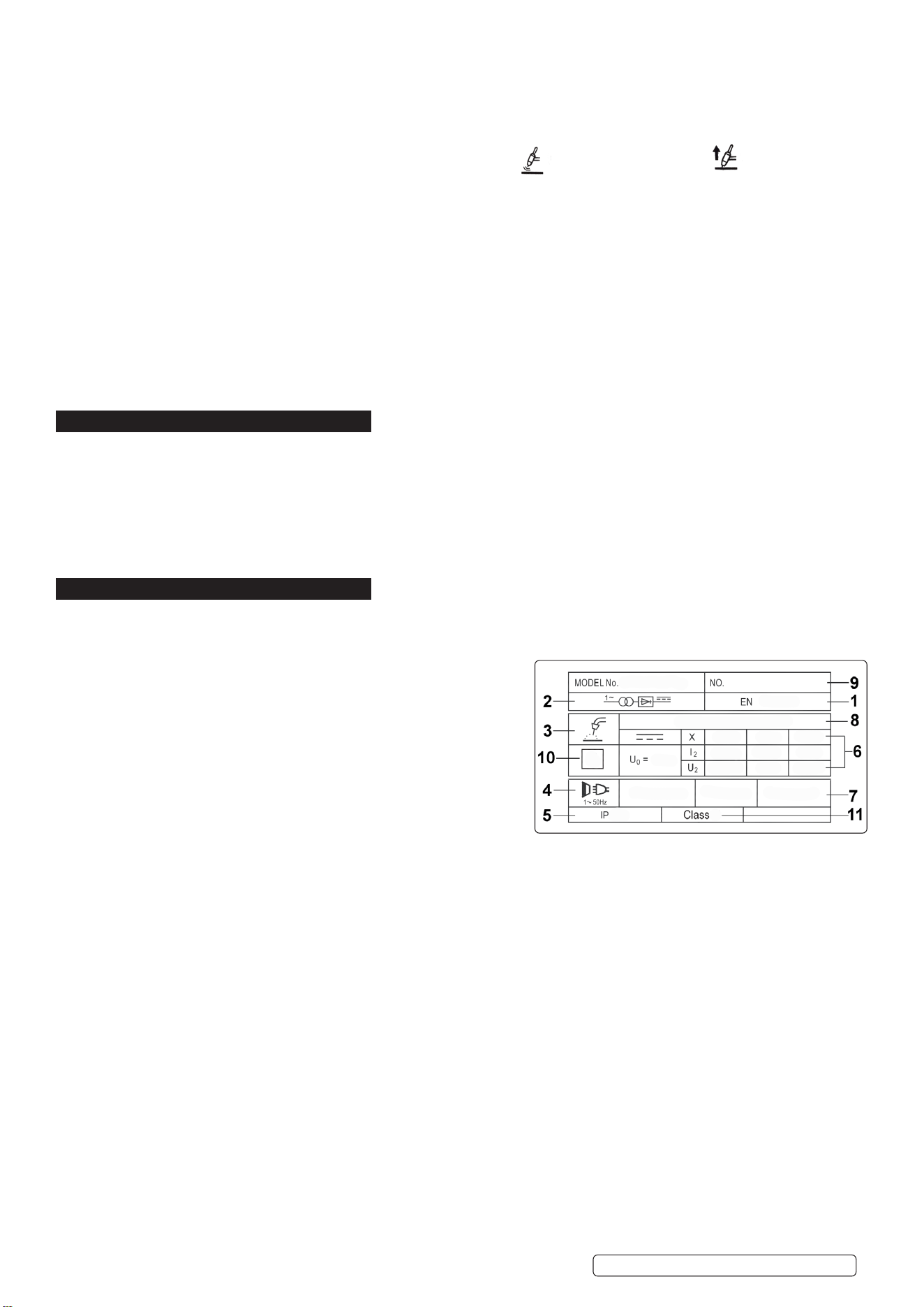
6. RATINGS PLATE SYMBOLS
6.1. Detailed technical data relative to the performance of the machine is located on the back panel plate. Please note that the ratings plate
shown below is an example only intended to assist with the explanations of symbols. To determine the correct technical values of the
machine in your possession, you must refer to the data plate.
6.2. On the rear of the inverter is the ratings plate, giving the following data:
1 - The BS/EU standard relating to the safety and construction of
arc welding and associated equipment.
2 - Inverter-transformer-rectifier symbols.
3 - Symbol indicates welding with a continuous flow of welding wire.
4 - Symbol for Single-phase AC supply.
5 - Rating of internal protection provided by casing.
6 - Output:
U0: Maximum open-circuit voltage.
I2, U2: Current and corresponding voltage.
X: Welding ratio based on a 10 minute cycle.
20% indicates 2 minutes welding and 8 minutes rest,
100% would indicate continuous welding.
7 - Mains Supply
U1: Rated supply voltage and frequency.
I1max: Maximum current. I1eff: Maximum effective current.
8 - A/V - A/V: Welding current adjustment range and corresponding voltages.
9- SerialNumber.Specificallyidentifieseachwelder.
10- Symbol for welding power sources which are suitable for supplying power to welding operations carried out in an environment with
increased risk of electric shock (if applicable).
11- Insulation Class.
Original Language Version
© Jack Sealey Limited
TIG200HFACDC.V2 Issue 3 (1) 31/01/2023
Sealey Group, Kempson Way, Suffolk Business Park, Bury St Edmunds, Suffolk. IP32 7AR
01284 757500 sales@sealey.co.uk www.sealey.co.uk
ENVIRONMENT PROTECTION
Recycle unwanted materials instead of disposing of them as waste. All tools, accessories and packaging should be sorted,
taken to a recycling centre and disposed of in a manner which is compatible with the environment. When the product
becomes completely unserviceable and requires disposal, drain any fluids (if applicable) into approved containers and
dispose of the product and fluids according to local regulations.
WEEE REGULATIONS
Dispose of this product at the end of its working life in compliance with the EU Directive on Waste Electrical and Electronic Equipment
(WEEE). When the product is no longer required, it must be disposed of in an environmentally protective way. Contact your local solid
waste authority for recycling information.
Note: It is our policy to continually improve products and as such we reserve the right to alter data, specifications and component parts without prior
notice. Pleasenotethatotherversionsofthisproductareavailable.Ifyourequiredocumentationforalternativeversions,pleaseemailorcall
our technical team on technical@sealey.co.uk or 01284 757505.
Important: No Liability is accepted for incorrect use of this product.
Warranty: Guarantee is 12 months from purchase date, proof of which is required for any claim.
Original Language Version
© Jack Sealey Limited
REGISTER YOUR
PURCHASE HERE
TIG200HFACDC.V2 Issue 3 (1) 31/01/2023