

“Operating, servicing and maintaining
a passenger vehicle or off-road
vehicle can expose you to chemicals
including engine exhaust, carbon
monoxide, phthalates, and lead, which
are known to the State of California
to cause cancer and birth defects or
other reproductive harm. To minimize
exposure, avoid breathing exhaust, do
not idle the engine except as necessary,
service your vehicle in a well-ventilated
area and wear gloves or wash your
hands frequently when servicing your
vehicle. For more information go to
www.P65Warnings.ca.gov/passenger-
vehicle.”
WARNING
– California
Proposition 65

FOREWORD
Dear Customer,
Thank you for selecting your new Kia vehicle.
As a global car manufacturer focused on building high-quality vehicles with excep
-
tional value, Kia is dedicated to providing you with a customer service experience that
exceeds your expectations.
An authorized Kia dealership where factory-trained technicians, recommended spe
-
cial tools, and genuine Kia replacement parts are provided can help if you need tech
-
nical assistance.
This Owner's Manual will acquaint you with the operation of features and equipment
that are either standard or optional on this vehicle, along with the maintenance
needs of this vehicle. Therefore, you may find some descriptions and illustrations not
applicable to your vehicle. You are advised to read this publication carefully and follow
the instructions and recommendations. Please always keep this manual in the vehicle
for your, and any subsequent owner's, reference.
All information contained in this Owner's Manual was accurate at the time of publica
-
tion. However, as Kia continues to make improvements to its products, the company
reserves the right to make changes to this manual or any of its vehicles at any time
without notice and without incurring any obligations.
Please drive safely, and enjoy your Kia vehicle!
2021 Kia America, Inc.
All rights reserved. May not be reproduced or translated in whole or in part without the written consent of Kia
America, Inc.
Printed in Korea


How to use this manual
We want to help you get the great
-
est possible driving pleasure from
your vehicle. Your Owner's Manual
can assist you in many ways.
We strongly recommend that you
read the entire manual. In order to
minimize the chance of death or
injury, you must read the WARNING
and CAUTION sections in the man
-
ual.
Illustrations complement the words
in this manual to best explain how
to enjoy your vehicle. By reading
your manual, you learn about fea
-
tures, important safety information,
and driving tips under various road
conditions.
The general layout of the manual is
provided in the Table of Contents.
Use the index when looking for a
specific area or subject, it has an
alphabetical listing of all information
in your manual.
Chapters: This manual has nine
chapters plus an index. Each chapter
begins with a brief list of contents
so you can tell at a glance if that
chapter has the information you
want.
You will find various WARNINGS,
CAUTIONS, and NOTICES in this
manual. These WARNINGS were
prepared to enhance your personal
safety. You should carefully read
and follow ALL procedures and rec
-
ommendations provided in these
WARNINGS, CAUTIONS and NOTICES.
WARNING
A WARNING indicates a situation in
which harm, serious bodily injury or
death could result if the warning is
ignored.
CAUTION
A CAUTION indicates a situation in
which damage to your vehicle could
result if the caution is ignored.
NOTICE
A NOTICE indicates interesting or
helpful information is being pro
-
vided.


Table of Contents
1
2
3
4
5
6
7
8
9
A
I
Hybrid system overview
Introduction
Your vehicle at a glance
Safety features of your vehicle
Features of your vehicle
Driving your vehicle
What to do in an emergency
Maintenance
Specifications, Consumer information and Reporting
safety defects
Abbreviation
Index


1Hybrid system overview
Hybrid system over view
PHEV (Plug-in Hybrid Electric Vehicle) system ...................1-2
HEV (Hybrid Electric Vehicle) system.................................... 1-3
Charging the plug-in hybrid vehicle....................................... 1-4
䳜 Charging information............................................................. 1-4
䳜 Charging time.......................................................................... 1-4
䳜 Charging types........................................................................ 1-4
䳜 Charging status ...................................................................... 1-5
䳜 AC charging connector lock................................................... 1-6
䳜 Scheduled charging ................................................................ 1-6
䳜 Charging precautions ............................................................. 1-8
䳜 AC charger .............................................................................1-10
䳜 Trickle charger (portable charging cable).........................1-13
䳜 How to disconnect charging connector in emergency...1-20
Driving the hybrid/plug-in hybrid vehicle...........................1-21
䳜 Starting the vehicle..............................................................1-21
䳜 Changing plug-in hybrid mode (Plug-in hybrid vehicle).1-22
䳜 Special features....................................................................1-23
䳜 Hybrid system gauge ..........................................................1-24
䳜 Warning and indicator lights...............................................1-27
䳜 LCD display messages .........................................................1-28
䳜 Energy flow ...........................................................................1-35
䳜 Aux. Battery Saver+ (Plug-in hybrid vehicle) ..................1-38
Components of the hybrid/plug-in hybrid vehicle ............1-40
䳜 Plug-in hybrid vehicle components...................................1-40
䳜 Hybrid vehicle components.................................................1-43
䳜 Service interlock connector ................................................1-47
䳜 If an accident occurs ............................................................1-47
䳜 When the hybrid vehicle shuts off ....................................1-48
Hybrid system overview
21
PHEV (Plug-in Hybrid Electric Vehicle) system
Hybrid system overview
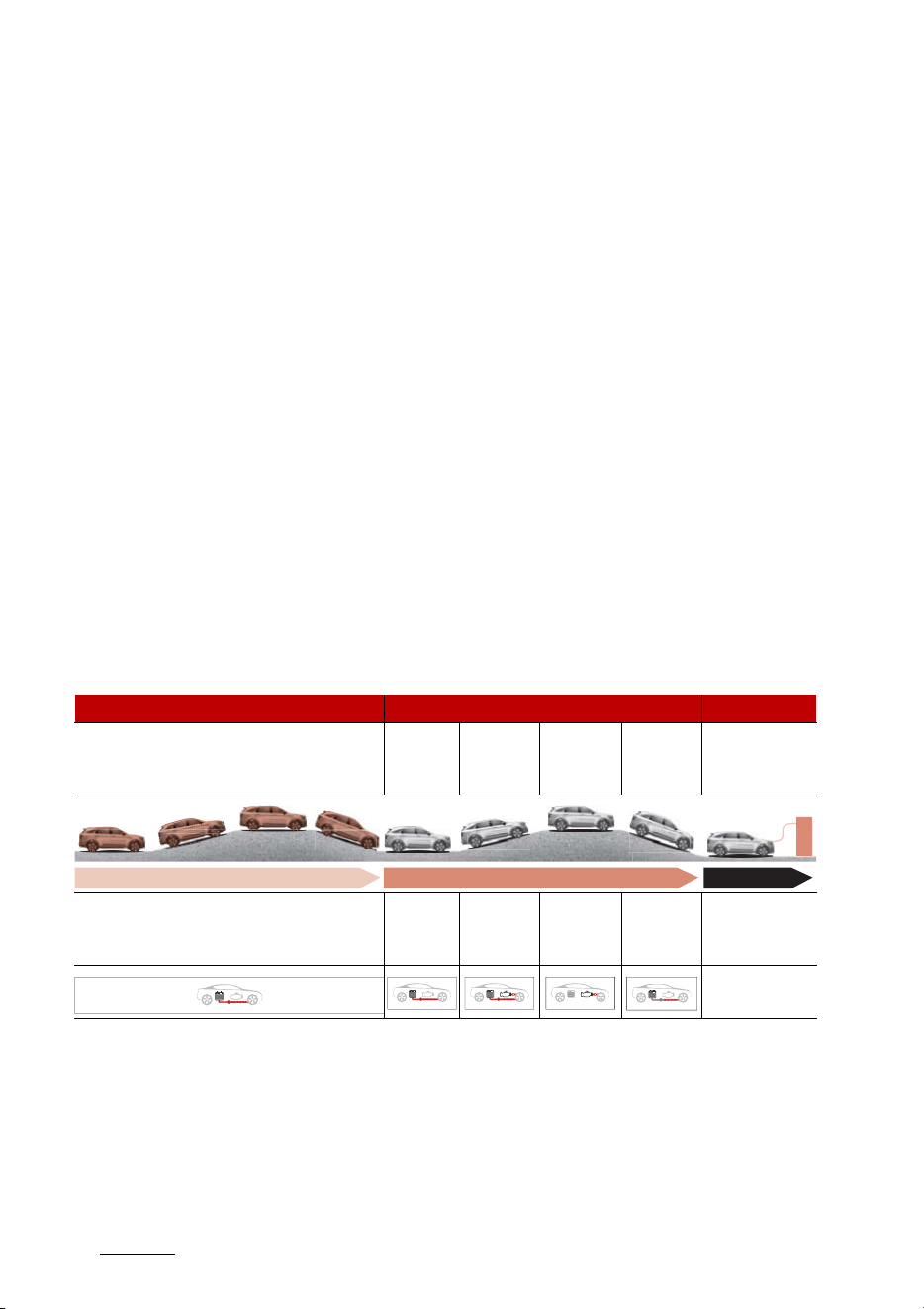
PHEV (Plug-in Hybrid Electric
Vehicle) system
The Kia Plug-in Hybrid Electric Vehi
-
cle (PHEV) shares the characteris
-
tics of both a conventional hybrid
electric vehicle and an all-electric
vehicle.
When used as a conventional hybrid
electric vehicle, the HEV computer
selectively operates between the
engine and the electric motor or
even both at the same time.
When it is operating in the electric
vehicle mode, the vehicle is driven
only using the electric motor over a
certain distance until the hybrid
battery becomes low. The driving
distance in EV mode depends on
customer driving style and road
conditions. Aggressive driving
maneuvers may at times temporar
-
ily enable the engine to operate.
The engine power could be limited
during emission reduction control
period at cold engine condition.
The hybrid battery can be fully
charged by connecting a plug to an
external electric power source.
An engine can be turned on due to
factors such as heater and a fre
-
quent operation of the accelerator
pedal by a driver in CD mode.
CD (Charge Depleting) Mode CS (Charge Sustaining) Mode Charging
Electric motor Motor
Engine +
Motor
Engine +
Motor or
Motor
Charging
Battery
charging
1. Electric Vehicle Mode
2. Start
up/Low
speed
3. High
speed
4. Acceler
-
ation
5. Decel
-
eration
6. External
Charging
3
1
1
Hybrid system overview HEV (Hybrid Electric Vehicle) system
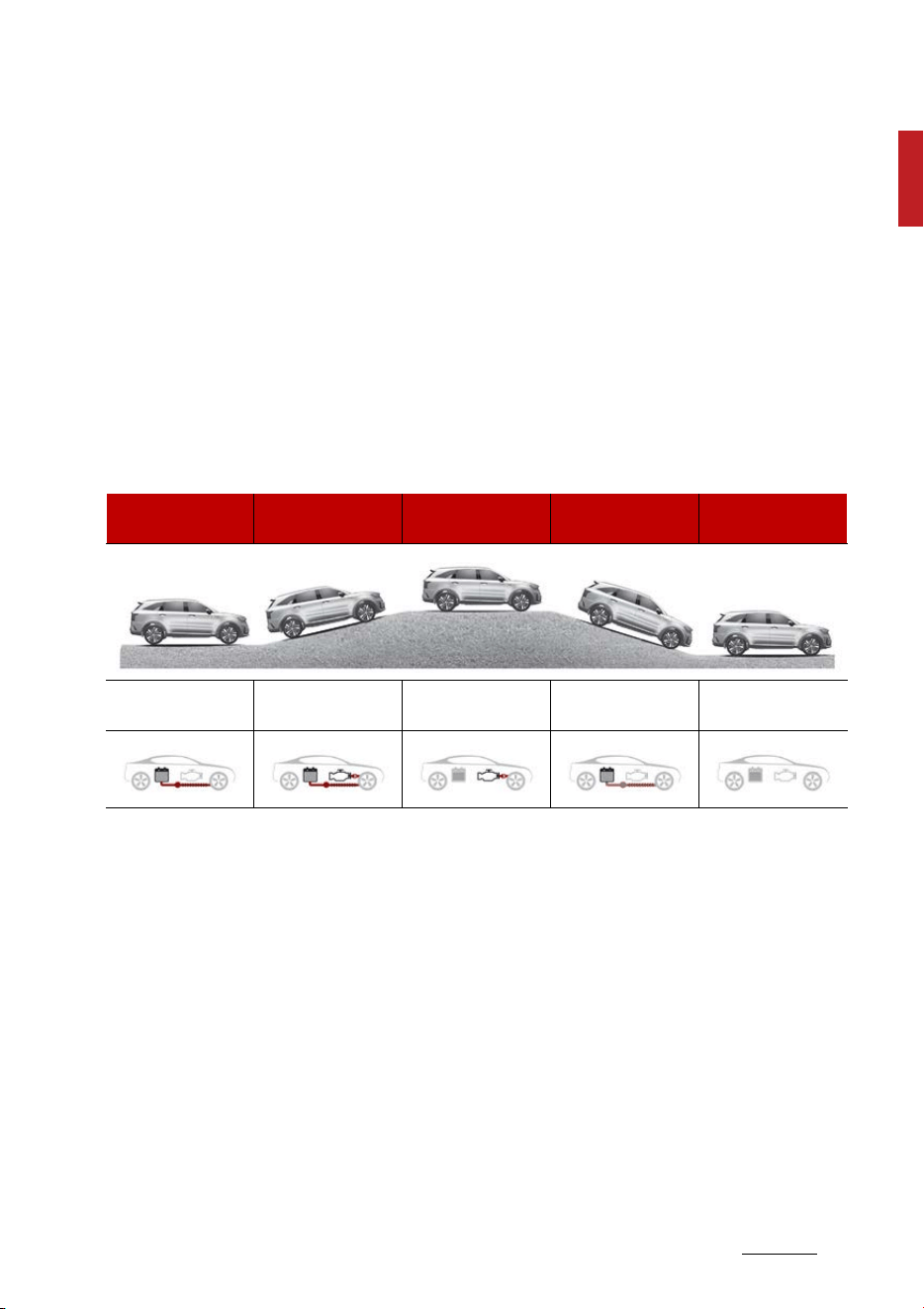
HEV (Hybrid Electric Vehicle)
system
The Kia Hybrid Electric Vehicle (HEV)
uses both the gasoline engine and
the electric motor for power. The
electric motor is run by a high-volt
-
age HEV battery.
Depending on the driving condi
-
tions, the HEV computer selectively
operates between the engine and
the electric motor or even both at
the same time.
Fuel efficiency increases when the
vehicle is driven by the electric
motor with the HEV battery.
The HEV battery charge must be
maintained, so at times the engine
will come on even at idle to act as a
generator. Charging also occurs
when decelerating or by regenera
-
tive braking.
Electric motor
Electric motor +
Engine
Engine Charging Engine OFF
1. Startup/Low
speed cruise
2. Acceleration 3. High speed cruise 4. Deceleration 5. Stop
Hybrid system overview
41
Charging the plug-in hybrid vehicle
Charging the plug-in hybrid vehicle
Charging information
䳜 AC Charger: The plug-in hybrid
vehicle is charged by plugging into
a AC charger installed in your
home or a public charging station.
(For further details, refer to "AC
charger" on page 1-10.)
䳜 Trickle Charger: The plug-in
hybrid vehicle can be charged by
using household electricity.
The electrical outlet in your home
must comply with regulations and
can safely accommodate the
Voltage/Current (Amps)/Power
(Watts) ratings specified on the
trickle charge. Use only as a
backup charger.
Charging time
䳜 AC Charger: Takes about 2 hours
15 minutes at room temperature
(Can be charged to 100%.).
Depending on the condition and
durability of the high-voltage
battery, charger specifications,
and ambient temperature, the
time required for charging the
high-voltage battery may vary.
䳜 Trickle Charger: For charging at
home. Please note that the Trickle
Charger is slower than the AC
Charger. Please note that the
Trickle Charger is slower than the
AC Charger, taking approximately
9 hours.
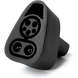
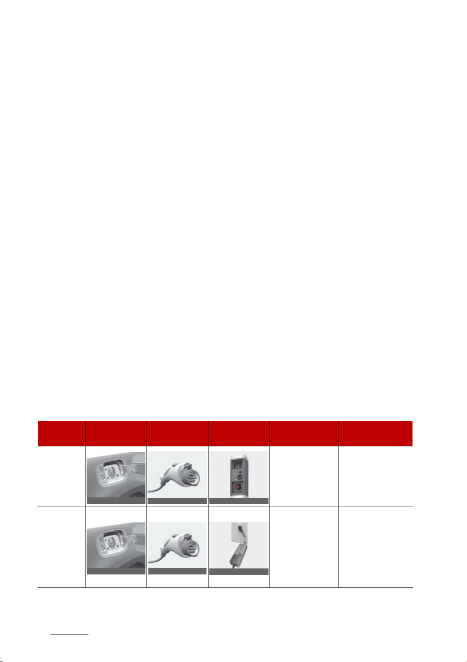
Charging types
䳜 Depending on the condition and durability of the high voltage battery, charger specifications, and ambi
-
ent temperature, the time required for charging the high voltage battery may vary.
䳜 Actual charger image and charging method may vary in accordance with the charger manufacturer.
Category
Charging Inlet
(Vehicle)
Charging Con
-
nector
Charging Outlet Charging Method Charging Time
AC Charger
AC charger
installed in homes
or public charging
stations
Approximately 2
hours 15 minutes
(to fully charge the
plug-in hybrid,
100%)
Trickle
Charger
Household current
For charging at
home. The included
Trickle charger
takes about 9 hours
at room tempera
-
ture (Can be
charged to 100%.).
OMQ4Q011001N
OMQ4Q011002N
OBDCPQ019003RE
OMQ4Q011001N
OMQ4Q011002N
OAEEQ016024
5
1
1
Hybrid system overview Charging the plug-in hybrid vehicle
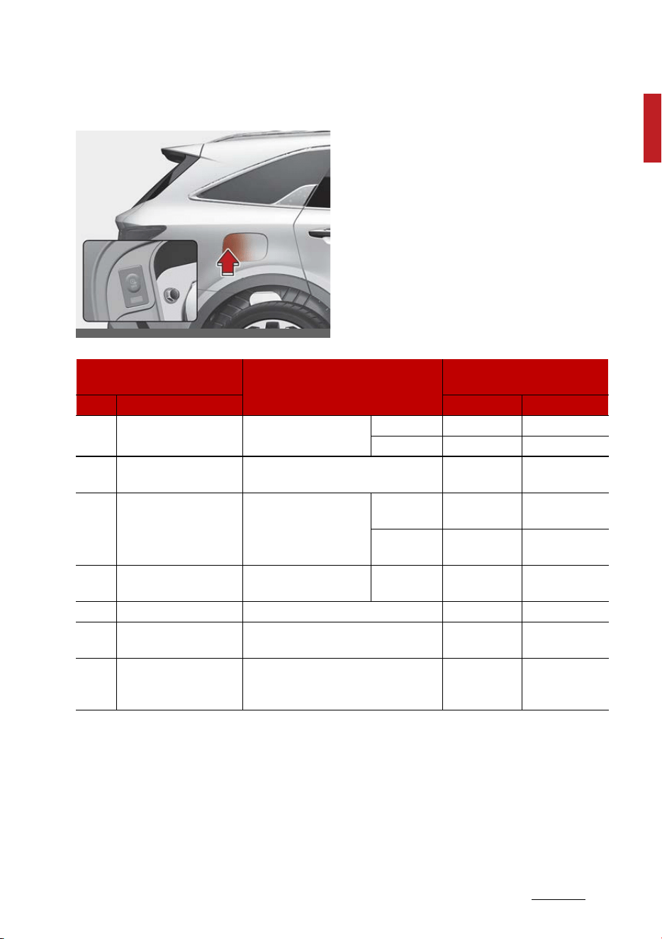
Charging status
You can check the charging status
at the outside of vehicle when
charging or using (it is not driving
status) the high-voltage battery.
It takes about 2 ~ 3 hours or more to
complete charging.
OMQ4PH010014L
Classification
Details
Operation of charging indicator
lamp
Mode Status Charging inlet Charging button
A READY Non-charging state
0 ~ 65 % On (Yellow) Off
65 ~ 100 % On (Green) Off
B
Aux. Battery Saver/High
voltage warning
Charging the 12V auxiliary battery /
High voltage warning state
On (Red) Off
C Charging Charging
0 ~ 65 %
Blinking (Yel
-
low)
Off
65 ~ 100 %
Blinking
(Green)
Off
D Charging complete
Charging completed
(turns off in 5 seconds)
100 %
On (Green) >
OFF
Off
E Charging failed Error while charging Blinking (Red) Off
F
Scheduled charging
standby
Reserved charging is operating (turns
OFF after 3 minutes)
Off On
G Error CAN communication error status
On (Green) >
On (Orange) >
On (Red)
Off
Hybrid system overview
61
Charging the plug-in hybrid vehicle
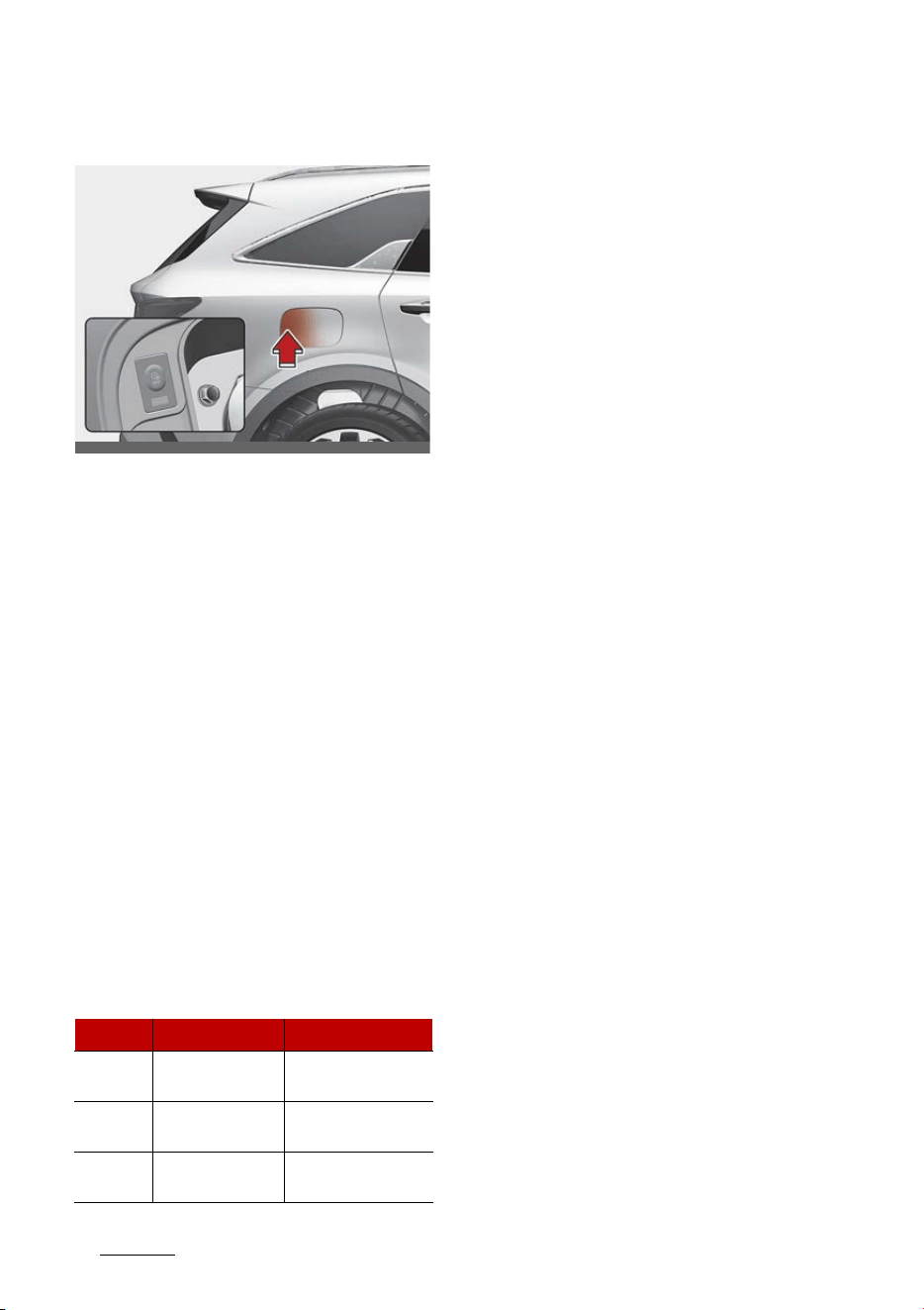
Checking charging status
You can check the charging status
at the outside of vehicle when
charging or using (it is not driving
status) the high-voltage battery.
It takes about 2 ~ 3 hours or more to
complete charging.
For more information about
charging status indicator, refer to
"Charging status" on page 1-5.
AC charging connector lock
This AC charging connector lock
function prevents an outsider from
removing the charging connector
from the charging inlet.
Connector lock
Always lock
The connector locks when the
charging connector is plugged into
the charging inlet. The connector is
locked until all doors are unlocked by
the driver. This mode can be used to
prevent charging cable theft.
䳜 If the charging connector is
unlocked when all doors are
unlocked, but the charging cable is
not disconnected within 15 sec
-
onds, the connector will be auto
-
matically locked again.
䳜 If the charging connector is
unlocked when all doors are
unlocked, but all doors are locked
again, immediately, the connec
-
tor will be automatically locked
again.
Lock while charging
The connector locks when charging
starts. The connector unlocks when
charging is complete.
Scheduled charging
䳜 You can set reserved charging
using the infotainment system.
Refer to the infotainment system
for detailed information about
setting reserved charging.
䳜 Scheduled charging can only be
done when using a AC charger or
the portable charging cable (ICCB:
In-Cable Control Box).
䳜 When scheduled charging is set
and the AC charger or the porta
-
ble charging cable (ICCB: In-Cable
Always lock Lock while charging
Before
charging
O X
While
charging
O O
After
charging
O X
OMQ4PH010014L
7
1
1
Hybrid system overview Charging the plug-in hybrid vehicle
Control Box) is connected for
charging, the scheduled charge
release button is illuminated (for
3 minutes) to indicate that sched
-
uled charging is set.
䳜 When scheduled charging is set,
charging is not initiated immedi
-
ately when the AC charger or por
-
table charging cable (ICCB: In-
Cable Control Box) is connected.
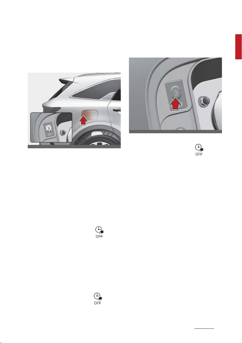
䳜 If charging is required immedi
-
ately, turn off the scheduled
charge using the infotainment
system and UVO application, or
press the vehicle's scheduled
charge release button ( )
more than 2 seconds.
䳜 When the scheduled charge is set,
the charge start time is calculated
by itself. In some cases, charging
may start immediately after con
-
necting the charger.
䳜 If you press the scheduled
charging deactivation ( ) but
-
ton to immediately charge the
battery, charging must be initi
-
ated 3 minutes after the charging
cable has been connected.
When you press the scheduled
charging deactivation ( ) but
-
ton for immediate charging, the
scheduled charge setting is not
completely deactivated. If you
need to completely deactivate the
scheduled charge setting, use the
infotainment system to finalize
the deactivation.
Refer to "AC charger" on page 1-
10 or "Trickle charger (portable
charging cable)" on page 1-13 for
details about connecting the AC
charger and the portable charger
(ICCB: In-Cable Control Box).
OMQ4PH011014L
OMQ4PH010015L
Hybrid system overview
81
Charging the plug-in hybrid vehicle
Charging precautions
AC Charger
WARNING
Fires caused by dust or water
Do not connect the charging cable
connector plug to the vehicle if there
is water or dust on the charging
inlet. Connecting while there is
water or dust on the charging cable
connector and plug may cause a fire
or electric shock.There may be a risk
of fire and injury when using old
worn out public electrical outlets.
WARNING
Interference with electronic medical
devices
When using medical electric devices
such as an implantable cardiac
pacemaker, make sure to ask the
medical team and manufacturer
whether charging your electric vehi
-
cle will impact the operation of the
medical devices. In some instances,
electromagnetic waves that are
generated from the charger can
seriously impact medical electric
devices such as an implantable car
-
diac pacemaker.
WARNING
Old or Worn out Electric Outlets
Do not use old or worn out electric
outlets to charge your vehicle. There
may be a risk of fire and injury when
using old worn out public electrical
outlets.
WARNING
Touching the charging connector
Do not to touch the charging con
-
nector, charging plug, and the
charging inlet when connecting the
cable to the charger and the
charging inlet on the vehicle. Doing
so may result in electrocution.
䳜 Comply with the following in order
to prevent electrical shock when
charging:
- Use a waterproof charger
- Make sure to not touch the
charging connector and
charging plug when your hand
is wet
- Do not charge when there is
lightning
OBDCPQ019003RE

9
1
1
Hybrid system overview Charging the plug-in hybrid vehicle
-Do not charge when the
charging connector and plug is
wet
WARNING
Charging cable
䳜 Immediately stop charging when
you find abnormal symptoms
(smell, smoke).
䳜 Replace the charging cable if the
cable coating is damaged to pre
-
vent electrical shock.
䳜 When connecting or removing the
charging cable, make sure to hold
the charging connector handle
and charging plug.
If you pull the cable itself (without
using the handle), the internal
wires may disconnect or get dam
-
aged.This may lead to electric
shock or fire.
WARNING
Cooling fan
Do not touch the cooling fan while
vehicle is charging. When the vehicle
is switched OFF while charging, the
cooling fan inside the motor com
-
partment may automatically oper
-
ate.
WARNING
Make sure to use the designated
charger for charging the vehi
-
cle.Using any other charger may
cause failure or lead to electric
shock or fire.
䳜 Always keep the charging connec
-
tor and charging plug in clean and
dry condition. Be sure to keep the
charging cable in a condition
where there is no water or mois
-
ture.
䳜 Make sure to use the designated
charger for charging the vehicle.
Using any other charger may
cause failure.
䳜 Before charging the battery, turn
the vehicle OFF.
䳜 Be careful not to drop the
charging connector. The charging
connector can be damaged.
䳜 Always inspect the charging con
-
nector terminals for damage or
overheating. Do not use if dam
-
aged, as this may damage the
vehicle side charge connector and
is not a warrantable repair.
Hybrid system overview
101
Charging the plug-in hybrid vehicle
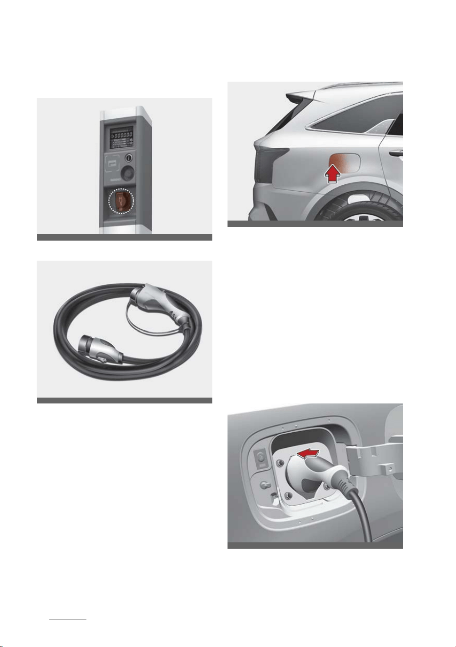
AC charger
AC Charger
AC charger cable
You can charge your vehicle by plug
-
ging into a public charger at a
charging station.
How to connect AC charger
1. Depress the brake pedal and apply
the parking brake.
2. Turn OFF all switches, move the
shift dial to P (Park), and turn OFF
the vehicle.
3. Open the charging inlet door by
pressing rear center edge of the
charging inlet door.
4. Remove any dust on the charging
connector and charging inlet.
5. Hold the charging connector han
-
dle.
Then, insert the charger into the
charging inlet, until you hear a
click sound. If it is not fully con
-
OBDCPQ019003RE
OMQ4Q011004N
OMQ4PHQ010040L
OMQ4PHQ010041L

11
1
1
Hybrid system overview Charging the plug-in hybrid vehicle
nected, a bad connection between
the charging connector and the
charging terminals may cause a
fire.
6. Check if the charging cable con
-
nection indicator ( ) of the
high voltage battery in the instru
-
ment cluster is turned ON.
Charging does not occur when the
indicator is OFF. When the
charging connector is not con
-
nected properly, reconnect the
charging cable to charge.
NOTICE
䳜 The charging is in progress only
with the shift dial is in P (Park).
Charging the battery with the
ENGINE START/STOP button in
the ACC position is possible. How
-
ever, it may discharge the 12V
battery. Thus, if possible, charge
the battery with the ENGINE
START/STOP button in the OFF
position.
䳜 Moving the shift dial from P (Park)
to R (Reverse)/N (Neutral)/D
(Drive) stops the charging pro
-
cess. To restart the charging pro
-
cess, move the shift dial to P
(Park), press the ENGINE START/
STOP button to the OFF position,
and disconnect the charging cable.
Then, connect the charging cable.
Charging connector lock mode
When the charging connector is
plugged into the charging inlet, the
connector lock timing varies with
the modes selected by the user set
-
tings menu or the infotainment
screen menu.
䳜 Always lock: The connector locks
when the charging connector is
plugged into the charging inlet.
䳜 Lock while charging: The connec
-
tor locks when charging starts.
The connector unlocks when
charging is completed.
For more details, refer to "AC
charging connector lock" on page 1-
6.
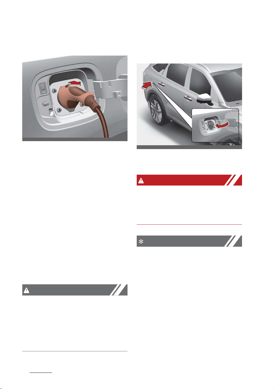
How to disconnect AC charger
1. The vehicle doors must be
unlocked in order to be able to
disconnect the charging connec
-
tor. A lock system prevents char
-
ger cable disconnection when the
vehicle's doors are locked.
CAUTION
In order to disconnect the charging
connector, unlock the doors to
unlatch the charging connector lock
system. If not, the charging connec
-
tor and the vehicle's charging inlet
may be damaged.
Hybrid system overview
121
Charging the plug-in hybrid vehicle
2. Hold the charging connector han
-
dle and pull it out.
To prevent charging cable theft,
the charging connector cannot be
disconnected from the inlet when
the doors are locked.
However, if the vehicle is in the
charging connector AUTO mode,
the charging connector automati
-
cally unlocks from the inlet when
charging is completed.
If the connector is not automati
-
cally unlocked after charging is
completed in AUTO mode, the
connector is unlocked when all of
the doors are unlocked.
For more details, refer to "AC
charging connector lock" on page
1-6.
CAUTION
When disconnecting the charging
connector, do not try to disconnect
it by force while not pressing the
release button. This may damage
the charging connector and vehicle
charging inlet.
3. Close the charging door by press
-
ing the rear center edge of the
charging door.
* The charging door does not have
a locking system.
WARNING
Do not modify or disassemble the
charging cable components. It may
cause a fire or an electric shock with
personal injury.
NOTICE
䳜 If you cannot open the charging
door due to freezing weather, tap
lightly or remove any ice near the
charging door. Do not try to forci
-
bly open the charging door. If you
open it by force, the charging
door may be damaged.
䳜 Keep the charging connector and
the charging plug clean and dry.
The charging cable should be also
kept dry.
OMQ4PH010010L
OMQ4011005N
13
1
1
Hybrid system overview Charging the plug-in hybrid vehicle
䳜 Use an air gun to blow any foreign
substances from the charging
connector and the charging plug.
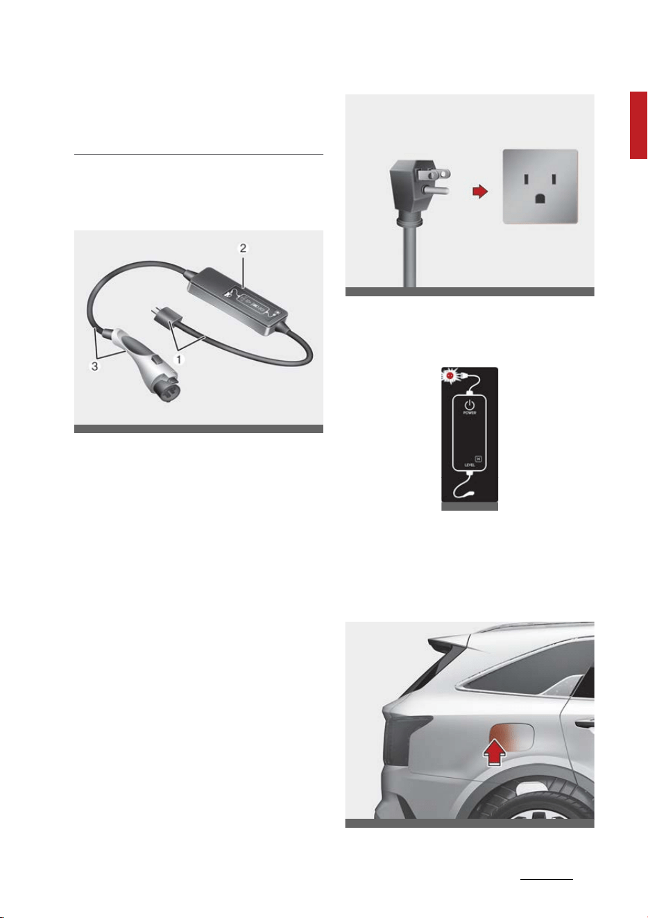
Trickle charger (portable charging
cable)
Trickle charger can be used if AC
Charger is unavailable.
1. Plug and cable
2. Control box (ICCB)
3. Charging connector/cable
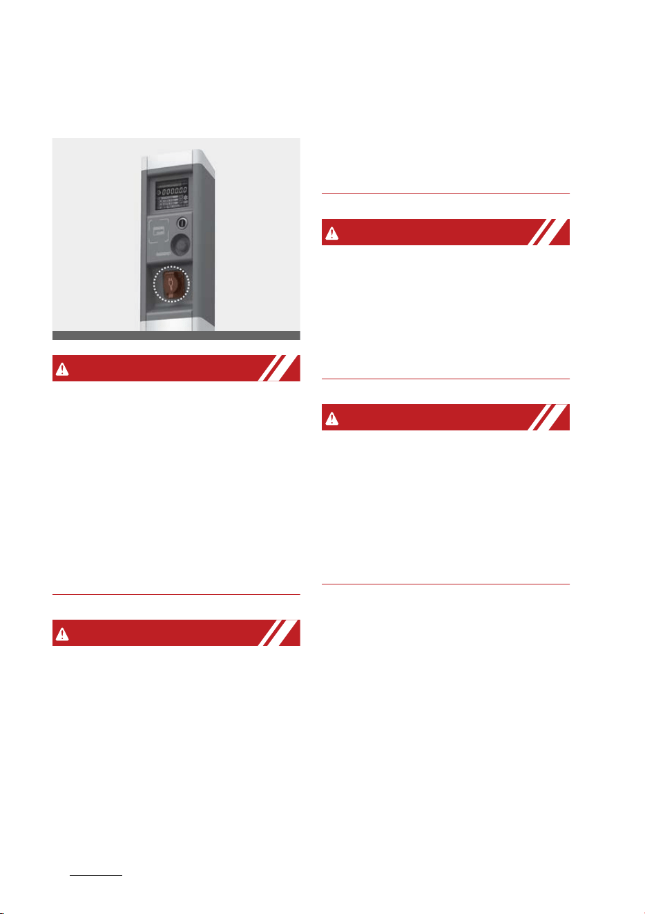
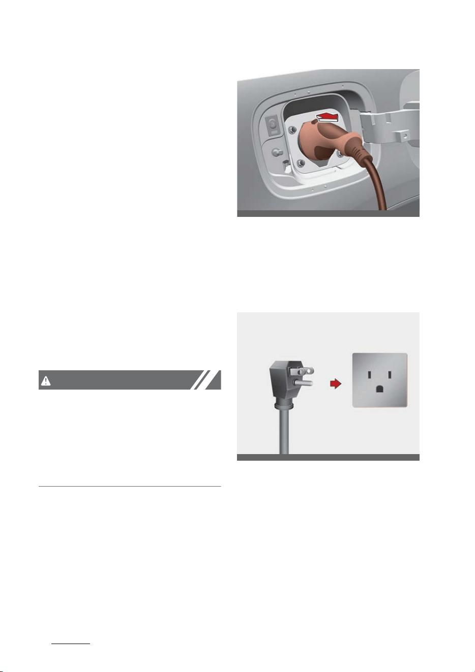
How to connect portable charging
cable (ICCB: In-Cable Control Box)
1. Turn OFF all switches, move the
shift dial to P (Park), and turn OFF
the vehicle.
2. Connect the plug to a household
electric outlet.
3. Make sure that the power con
-
nection indicator (green) lights in
the control box.
4. Depress the brake pedal and apply
the parking brake.
5. Open the charging inlet door by
pressing rear center edge of the
charging inlet door.
OMQ4Q011005N
OMQ4Q011003N
OCDPQ019051
OMQ4PHQ010040L
Hybrid system overview
141
Charging the plug-in hybrid vehicle
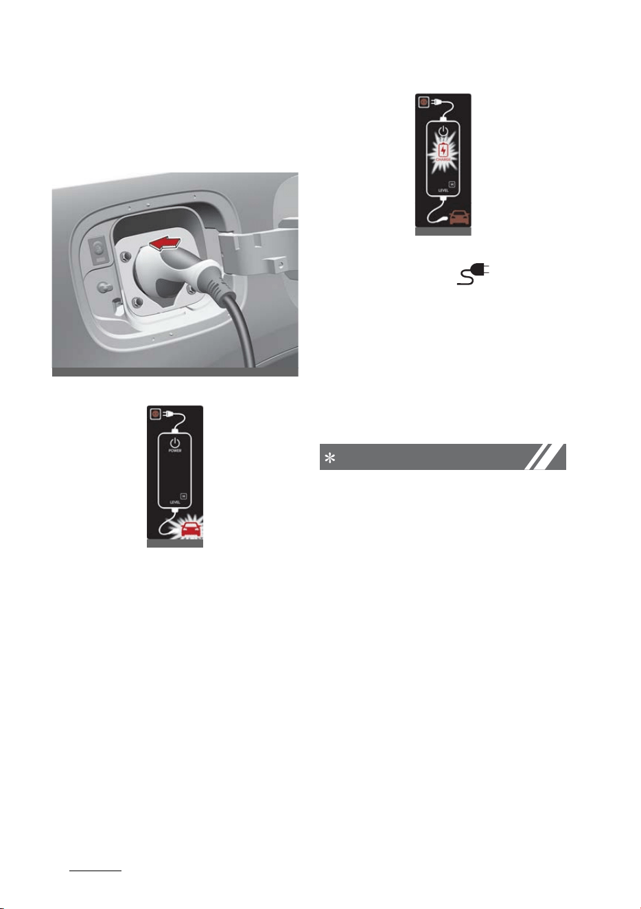
6. Remove any dust on the charging
connector and charging inlet.
7. Hold the charging connector han
-
dle.
Vehicle connection
Then, insert it into the charging
inlet, until you hear a click sound.
If it is not fully connected,
improper connection between the
charging connector and the
charging terminals are a potential
fire hazard.
8. Charging starts automatically and
the charging light blinks.
9. Check if the charging cable con
-
nection indicator ( ) of the
high voltage battery in the instru
-
ment cluster is turned ON.
Charging does not occur when the
indicator is OFF. When the
charging connector is not con
-
nected properly, reconnect the
charging cable to charge.
NOTICE
䳜 The charging is in progress only
with the shift dial is in P (Park).
Charging the battery with the
ENGINE START/STOP button in
the ACC position is possible. How
-
ever, it may discharge the 12V
battery. Thus, if possible, charge
the battery with the ENGINE
START/STOP button in the OFF
position.
䳜 Moving the shift dial from P (Park)
to R (Reverse)/N (Neutral)/D
(Drive) stops the charging pro
-
cess. To restart the charging pro
-
cess, move the shift dial to P
(Park), press the ENGINE START/
STOP button to the OFF position,
and disconnect the charging cable.
OMQ4PHQ010041L
OCDPQ019052
OCDPQ019053
15
1
1
Hybrid system overview Charging the plug-in hybrid vehicle
Then, connect the charging cable
and restart the charging process.
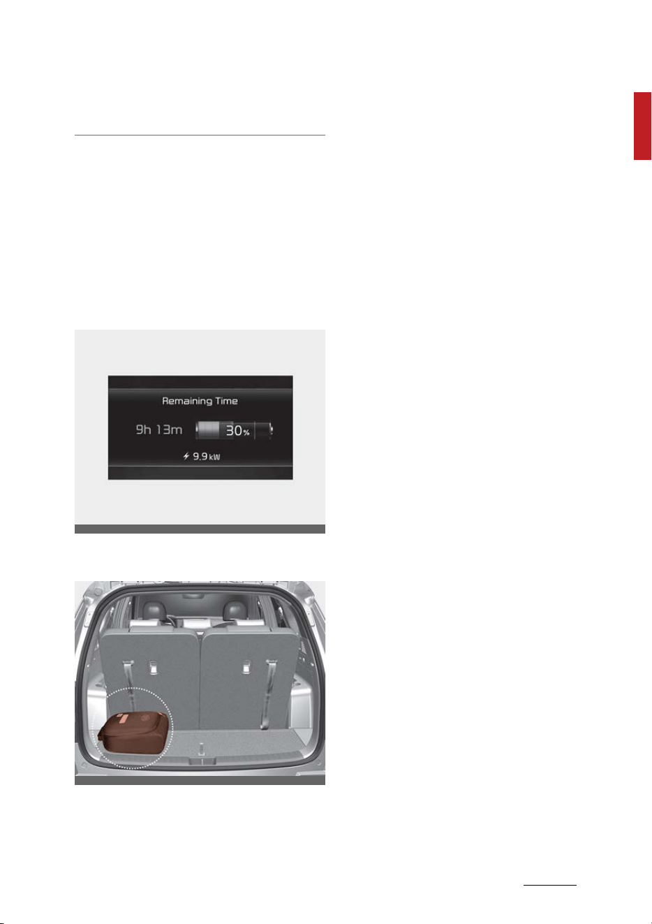
10.After charging has started, the
estimated charging time is dis
-
played on the instrument cluster
for about 1 minute. It is also dis
-
played, when the driver's door is
opened with charging in progress.
When scheduled charging is set,
the estimated charging time is
displayed as "--".
Charging cable storage
We recommend that the trickle
charger cable should be put in the
storage box after use.
OMQ4PHQ010048L
OMQ4PHQ010043L
Hybrid system overview
161
Charging the plug-in hybrid vehicle
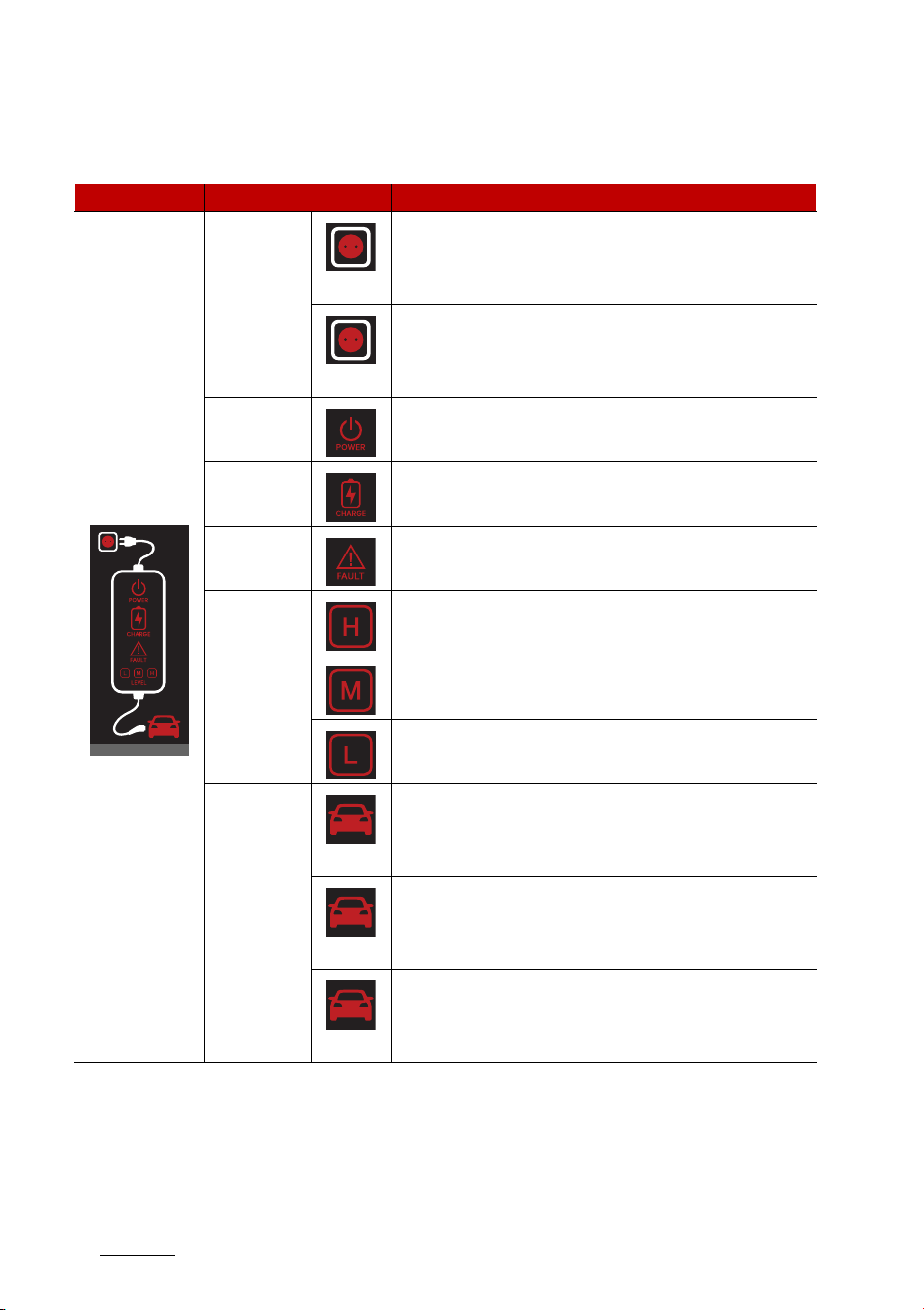
Charging status indicator lamp for portable charging cable
Control Box Indicator Details
PLUG
(Green)
On: Power on
Blink: Plug temperature sensor failure
(Red)
On: Plug high temperature protection
Blink: Plug high temperature warning
POWER On: Power on
CHARGE
Blink: Charging In power saving mode, only the CHARGE
indicator is illuminated.
FAULT Blink: Charging interrupted
CHARGE
LEVEL
Charging current 12A
Charging current 10A
Charging current 8A
VEHICLE
(Green)
Charging connector plugged
(Blue)
Charging
(Red)
Blink: Charging impossible
OCDPQ019047
17
1
1
Hybrid system overview Charging the plug-in hybrid vehicle
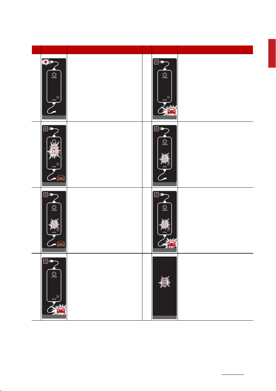
NO Control Box Status/Diagnosis/Countermeasure NO Control Box Status/Diagnosis/Countermeasure
1
䳜 Charging connector plugged into
vehicle (Green ON)
䳜 Plug temperature sensor fail
-
ure (Green blink)
䳜 Plug high temperature protec
-
tion (Red blink)
䳜 Plug high temperature warning
(Red ON)
Have the system inspected by an
authorized Kia dealer.
2
䳜 Charging connector plugged into
vehicle (Green ON)
3
䳜 While charging
- Charge indicator (Green
blink)
- Vehicle indicator (Blue ON)
4
䳜 Before plugging charging con
-
nector into vehicle (Red blink)
- Abnormal temperature
- ICCB (In-Cable Control Box)
failure
Have the system inspected by an
authorized Kia dealer.
5
䳜 Plugged into vehicle (Red blink)
- Diagnostic device failure
- Current leakage
- Abnormal temperature
Have the system inspected by an
authorized Kia dealer.
6
䳜 After plugging charging connec
-
tor into vehicle (Red blink)
- Communication failure
Have the system inspected by an
authorized Kia dealer.
7
䳜 Plug temperature sensor fail
-
ure (Green blink)
䳜 Plug high temperature protec
-
tion (Red blink)
䳜 Plug high temperature warning
(Red ON)
Have the system inspected by an
authorized Kia dealer.
8
䳜 Power saving mode
- 3 minutes after charging
starts (Green blink)
OCDPQ019051
OCDPQ019052
OCDPQ019053
OCDPQ019054
OCDPQ019055
OCDPQ019056
OCDPQ019052
ODEEV018071
Hybrid system overview
181
Charging the plug-in hybrid vehicle
How to disconnect portable
charging cable (ICCB: In-Cable Con
-
trol Box)
1. Before disconnecting the charging
connector, make sure the doors
are unlocked. When the door is
locked, the charging connector
lock system will not allow discon
-
nection. To prevent charging cable
theft, the charging connector
cannot be disconnected from the
inlet when the doors are locked.
However, if the vehicle is in the
charging connector AUTO mode,
the charging connector automati
-
cally unlocks from the inlet when
charging is completed.
For more details, refer to "AC
charging connector lock" on page
1-6.
CAUTION
In order to disconnect the charging
connector, unlock the doors to
unlatch the charging connector lock
system. If not, the charging connec
-
tor and the vehicle's charging inlet
may be damaged.
2. While holding the charging con
-
nector, pressing the locking
release button and then pull it
out.
3. Make sure to securely close the
charging door.
4. Disconnect the plug from the
household electric outlet. Do not
pull the cable when disconnecting
the plug.
5. Close the protective cover for the
charging connector so that for
-
eign material cannot get into the
terminal.
6. Put the charging cable inside the
cable compartment to protect it.
OMQ4PH010010L
OMQ4Q011003N

19
1
1
Hybrid system overview Charging the plug-in hybrid vehicle
Precautions for portable charging
cable (ICCB: In-Cable Control Box)
䳜 Use the portable charging cable
that is certified by Kia.
䳜 Do not try to repair, disassemble,
or adjust the portable charging
cable.
䳜 Do not use an extension cord or
adapter.
䳜 Stop using immediately if failure
warning light occurs.
䳜 Do not touch the plug and
charging connector with wet
hands.
䳜 Do not touch the terminal part of
the AC charging connector and
the AC charging inlet on the vehi
-
cle.
䳜 Do not connect the charging con
-
nector to voltage that does not
comply with regulations.
䳜 Do not use the portable charging
cable if it is worn out, exposed, or
there exists any type of damage
on the portable charging cable.
䳜 If the ICCB case and AC charging
connector is damaged, cracked, or
the wires are exposed in any way,
do not use the portable charging
cable.
䳜 Do not let children operate or
touch the portable charging cable.
䳜 Keep the control box free of
water.
䳜 Keep the AC charging connector
or plug terminal free of foreign
substances.
䳜 Do not step on the cable or cord.
Do not pull the cable or cord and
do not twist or bend it.
䳜 Do not charge when there is light
-
ning.
䳜 Do not drop the control box or
place a heavy object on the con
-
trol box.
䳜 Do not place an object that can
generate high temperatures near
the charger when charging.
䳜 Charging with the worn out or
damaged household electric out
-
let can result in a risk of electric
shock. If you are in doubt to the
household electric outlet condi
-
tion, have it checked by a licensed
electrician.
䳜 Stop using the portable charging
cable immediately if the house
-
hold electric outlet or any compo
-
nents is overheated or you notice
burnt odors.
Actions to be taken for electric
vehicle charging issues
When you cannot charge the high
voltage battery after connecting
the charger, check the following:
1. Check the charging settings for
the vehicle.
(e.g. when scheduled charging is
set, charging is not initiated
immediately when the AC char
-
ger or portable charger is con
-
nected.)
Hybrid system overview
201
Charging the plug-in hybrid vehicle
2. Check the operation status of the
AC charger, portable charger.
(Refer to "Charging status indica
-
tor lamp for portable charging
cable" on page 1-16.)
* Actual method for indicating the
charging status may vary in
accordance with the charger
manufacturer.
3. When the vehicle does not charge
and a warning message appears
on the instrument cluster, check
the corresponding message.
4. If the vehicle is properly charged
when charged with another nor
-
mally working charger, contact
the charger manufacturer.
5. If the vehicle does not charge
when charged with another nor
-
mally working charger, contact an
authorized Kia dealer for inspec
-
tion.
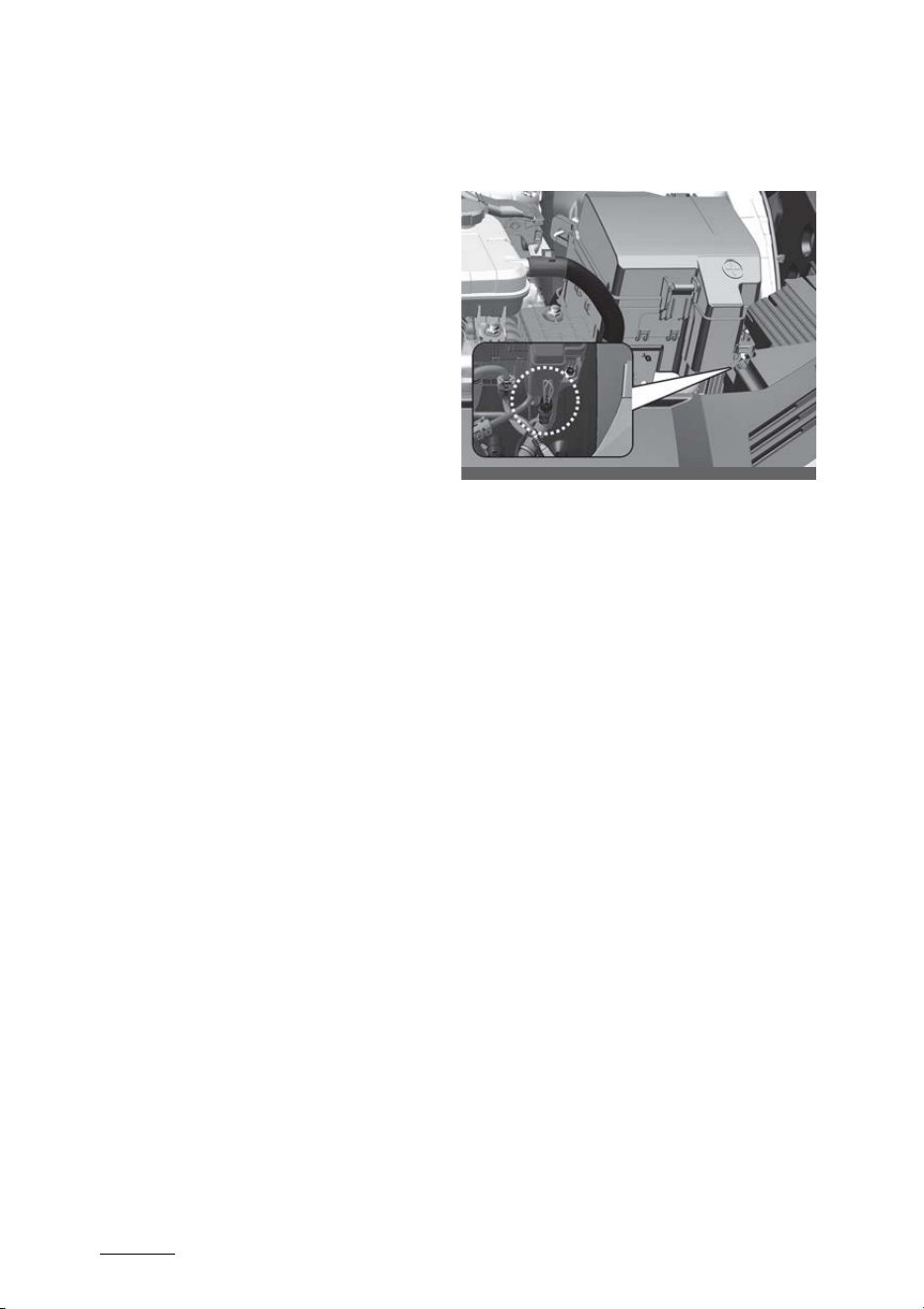
How to disconnect charging con
-
nector in emergency
If the charging connector does not
disconnect due to battery discharge
and/or failure of the electric sys
-
tem, open the hood and slightly pull
the emergency cable. The charging
connector will then disconnect.
If the charging door is not opened
immediately with the emergency
cable in operation, press the
charging door lightly and pull the
emergency cable again.
The charging cable lock may not
work properly when foreign materi
-
als such as dust enters the cable or
the cable is encrusted with ice.
In that case, the charging cable may
not be disconnected from the car.
If this happens, open the hood and
pull the emergency cable lightly 2 to
3 times before disconnecting.
OMQ4H070020

21
1
1
Hybrid system overview Driving the hybrid/plug-in hybrid vehicle
Driving the hybrid/plug-in
hybrid vehicle
Starting the vehicle
Vehicles with smart key system
1. Carry the smart key or leave it
inside the vehicle.
2. Make sure the parking brake is
firmly applied.
3. Place the shift dial in P (Park).
With the shift dial in N (Neutral),
you cannot start the vehicle.
4. Depress the brake pedal.
5. Press the ENGINE START/STOP
button. If the hybrid system
starts, the ( ) READY/ON indica
-
tor will come on.
Whether the engine is cold or
warm, it should be started with
-
out depressing the accelerator.
After following the start proce
-
dures, ( ) READY/ON indicator on
the instrument cluster will turn on.
For more details, please refer to
"Starting the vehicle" on page 1-21.
Economical and safe operation of
Hybrid system
䳜 Drive smoothly. Accelerate at a
moderate rate and maintain a
steady cruising speed. Do not
make "jackrabbit" start. Do not
race between stoplights.
Avoid heavy traffic whenever
possible. Always maintain a safe
distance from other vehicles so
you can avoid unnecessary brak
-
ing. This also reduces brake wear
out.
䳜 The regenerative brake generates
energy when the vehicle deceler
-
ates.
䳜 When the hybrid battery power is
low, the hybrid system automati
-
cally recharges the hybrid bat
-
tery.
䳜 When the engine is running with
the shift dial in N (Neutral), the
hybrid system cannot generate
electricity. The hybrid battery
cannot recharge with the shift dial
in N (Neutral).
NOTICE
In the hybrid system, the engine
automatically runs and stops. When
the hybrid system operates, the
( ) indicator is illuminated.
In the following situation, the engine
may operate automatically.
䳜 When the engine is ready to run.
䳜 When the hybrid battery is being
charged.
䳜 Depending on the temperature
condition of the hybrid battery.
Hybrid system overview
221
Driving the hybrid/plug-in hybrid vehicle
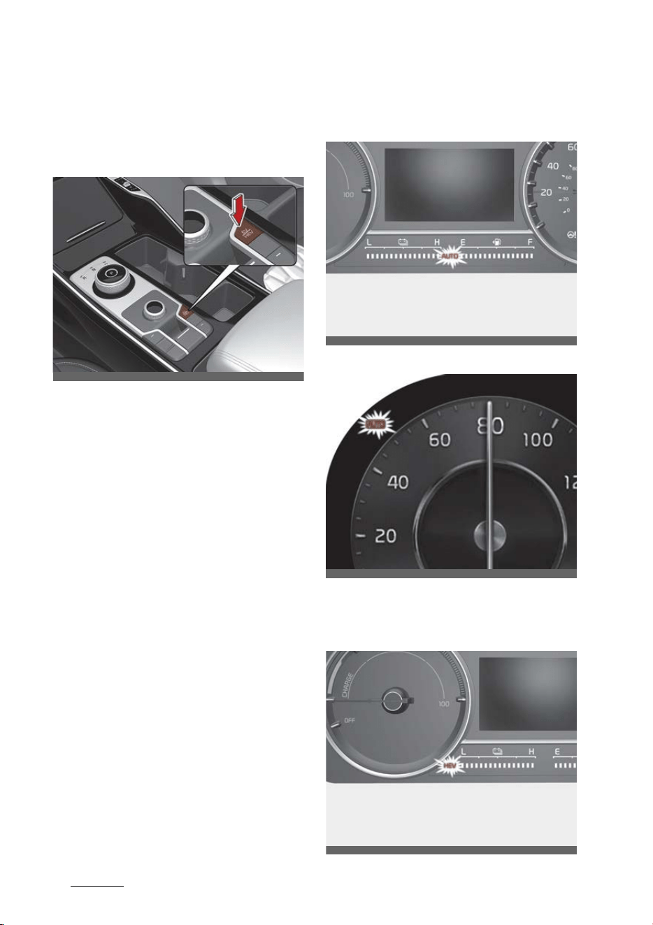
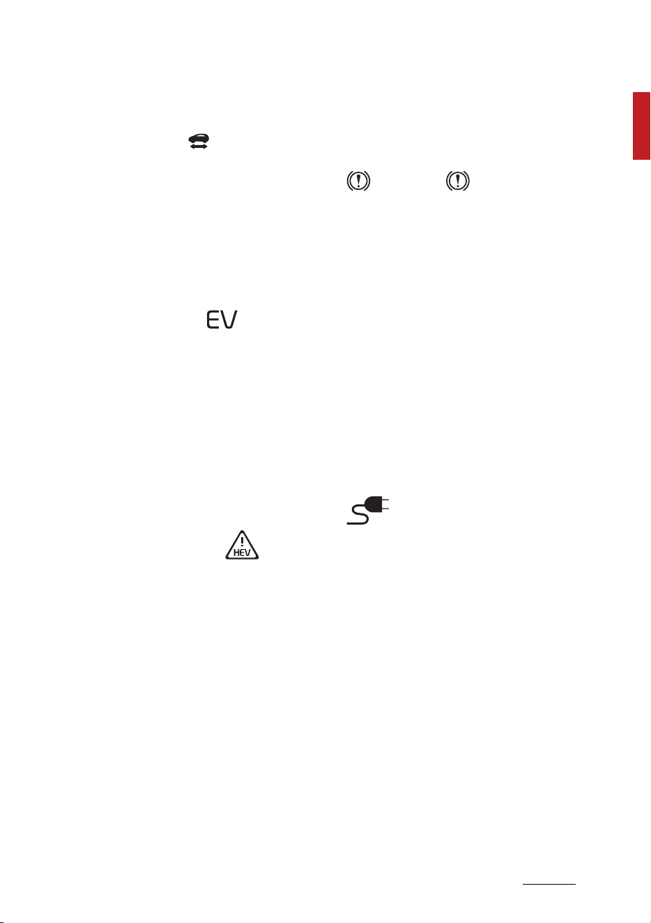
Changing plug-in hybrid mode
(Plug-in hybrid vehicle)
EV/HEV button
Whenever you press the [EV/HEV]
button, Plug-in hybrid system drive
mode will be changed in sequential
as:
Automatic (AUTO) mode - Hybrid
(CS) mode - Electric (CD) mode.
Each time the mode is changed a
corresponding LED is displayed on
the instrument cluster as follows.
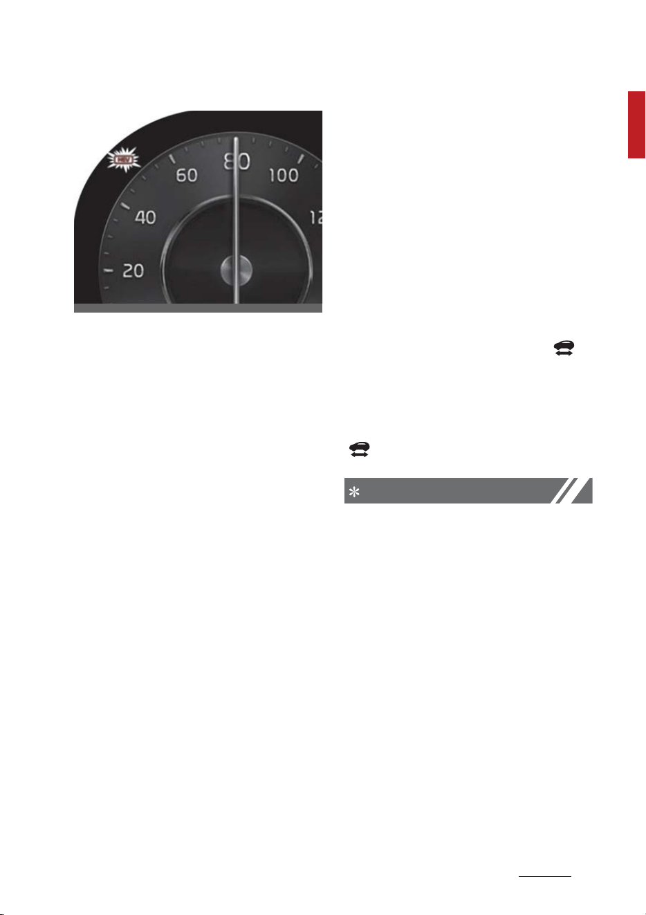
Automatic (AUTO) mode
Type A
Type B
Hybrid (CS) mode
Type A
OMQ4PHQ010044L
OMQ4Q011006N
OMQ4041110N
OMQ4PHQ010046L
23
1
1
Hybrid system overview Driving the hybrid/plug-in hybrid vehicle
Type B
Special features
Hybrid vehicles sound different from
gasoline engine vehicles. When the
hybrid system operates, you may
hear a sound from the hybrid bat
-
tery system under the passenger
side seat floor. If you apply the
accelerator pedal rapidly, you may
hear an unconventional sound.
When you apply the brake pedal,
you may hear a sound from the
regenerative brake system. When
the hybrid system is turned off or
on, you may hear a sound in the
engine compartment. If you depress
the brake pedal repeatedly when
the hybrid system is turned on, you
may hear a sound in the engine
compartment. None of these
sounds indicate a problem. These
are normal characteristics of hybrid
vehicles.
If any of the following occurs, it's a
normal condition if you hear a motor
sound in the engine compartment:
䳜 After turning off the hybrid sys
-
tem, the brake pedal is released.
䳜 When the hybrid system is turned
off, the brake pedal is applied.
䳜 When the driver door is opened.
When the hybrid system is turned
ON, the gasoline engine may run or
may not. In this situation, you may
feel a vibration. This does not indi
-
cate a malfunction. When the ( )
indicator illuminates, the hybrid
system is ready to begin driving.
Even if the engine is off, you can
operate the vehicle as long as the
( ) indicator is illuminated.
NOTICE
The hybrid system contains many
electronic components. High volt
-
age components, such as cables and
other parts, may emit electromag
-
netic waves. Even when the electro
-
magnetic cover blocks
electromagnetic emissions, electro
-
magnetic waves may have an effect
on electronic devices. When your
vehicle is not used for a long period
of time, the hybrid system will dis
-
charge. You need to drive the vehicle
several times a month. We recom
-
mend driving at least for 1 hour or
10 miles (16 km). When the hybrid
battery is discharged, or when it is
OMQ4041111N
Hybrid system overview
241
Driving the hybrid/plug-in hybrid vehicle
impossible to jump start the vehicle,
contact your authorized Kia dealer.
When you start the hybrid system
with the shift dial in P (Parking), the
( ) indicator illuminates on the
instrument cluster. The driver can
drive the vehicle, even when the
gasoline engine is off.
WARNING
䳜 When you leave the vehicle, you
should turn OFF the hybrid sys
-
tem or locate the shift dial in P
(Park). When you depress the
accelerator pedal by mistake, or
when the shift dial is not in P
(Park), the vehicle will abruptly
move, possibly resulting in serious
injury or death.
Virtual Engine Sound System
(VESS)
Virtual Engine Sound System gener
-
ates engine sound for pedestrians
to hear vehicle sound because there
is limited sound while motor power
is used.
䳜 If the vehicle is moving at low
speed, the VESS will operate.
䳜 When the gear is shifted to R
(Reverse), an additional warning
sound will be heard.
What does regenerative braking
do?
It uses an electric motor when
decelerating and when braking and
transforms kinetic energy to elec
-
trical energy in order to charge the
high voltage battery.
Battery
䳜 The vehicle is composed of a high
voltage battery that drives the
motor and air conditioner, and a
12V lead battery with the HEV
battery that drives the lamps,
wipers, and audio system.
䳜 The 12V battery is automatically
charged when the vehicle is in the
ready ( ) mode.
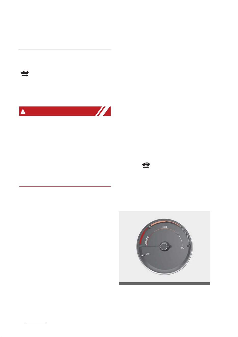
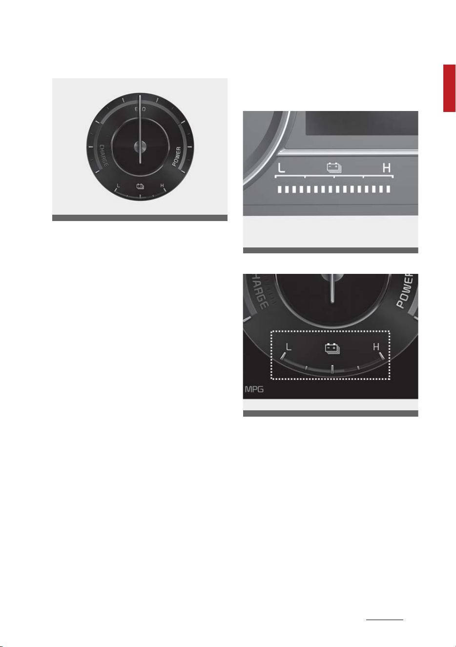
Hybrid system gauge
Power gauge
Type A
OMQ4H040105
25
1
1
Hybrid system overview Driving the hybrid/plug-in hybrid vehicle
Type B
The hybrid system gauge indicates
whether the current driving condi
-
tion is fuel efficient or not.
䳜 CHARGE:
Shows that the energy made by
the vehicle is being converted to
electrical energy. (Regenerated
energy)
䳜 ECO:
Shows that the vehicle is being
driven in an Eco-friendly manner.
䳜 POWER:
Shows that the vehicle is exceed
-
ing the Eco-friendly range.
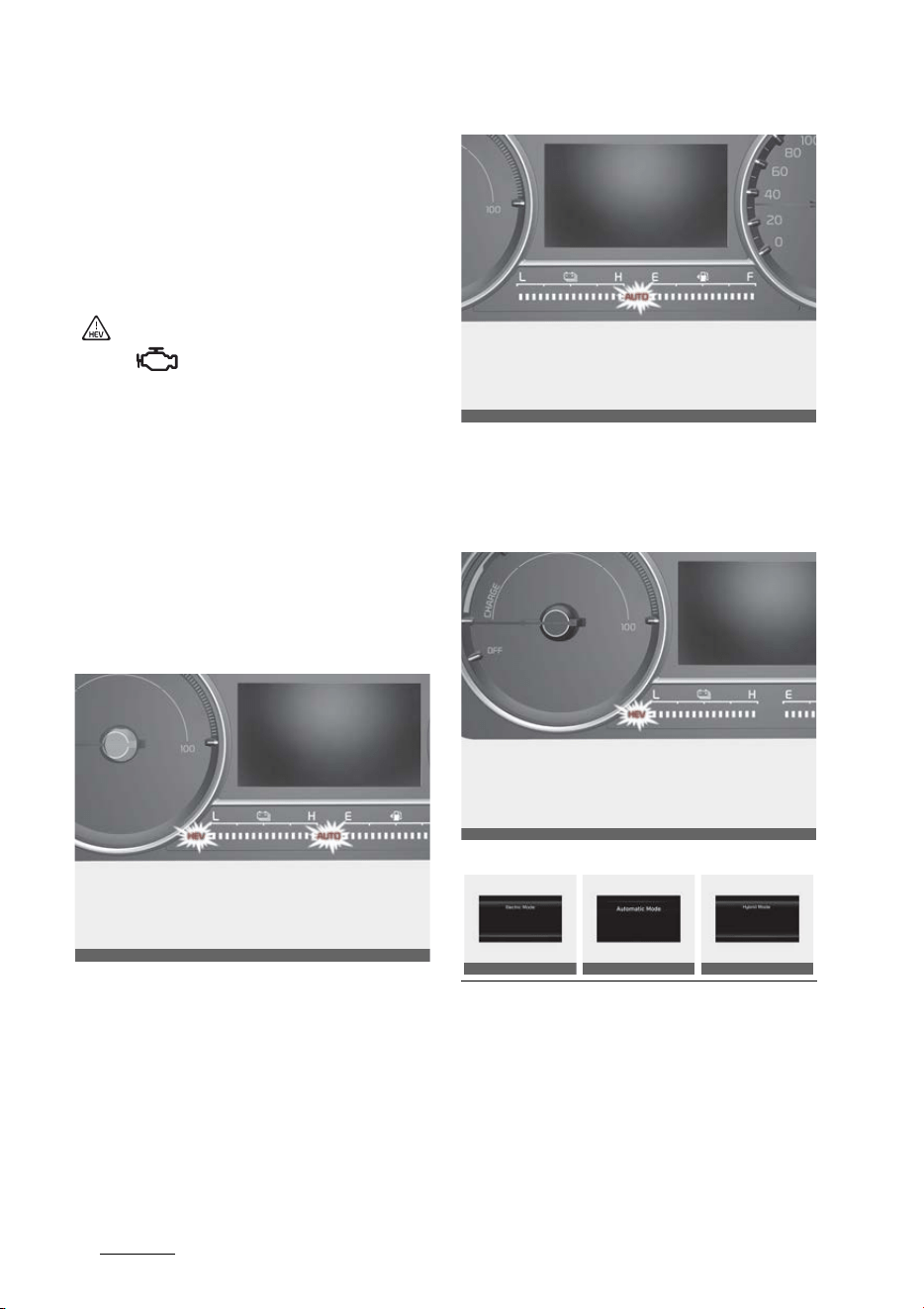
Hybrid battery SOC (State of
Charge) gauge
Type A
Type B
OMQ4H040103
OMQ4H040107
OMQ4AH040104
Hybrid system overview
261
Driving the hybrid/plug-in hybrid vehicle
This gauge indicates the remaining
hybrid battery power. If the SOC is
near the "L (Low)" level, the vehicle
automatically operates the engine
to charge the battery.
However, if the Service Indicator
( ) and Malfunction Indicator Lamp
(MIL) ( ) turn on when the SOC
gauge is near the "L (Low)" level,
have the vehicle be checked by an
authorized Kia dealer.
Plug-in hybrid mode indicator
(Plug-in hybrid vehicle)
䳜 CD (Charge Depleting, Electric)
mode: The high-voltage (hybrid)
battery is used to drive the vehi
-
cle.
䳜 AUTO mode: The AUTO mode will
automatically select from either
from Electric (CD) mode or Hybrid
(CS) mode by the system accord
-
ing to the driving condition.
䳜 CS (Charge Sustaining, Hybrid)
mode: The high-voltage (hybrid)
battery and gasoline engine is
used to drive the vehicle.
A corresponding message is dis
-
played to indicate the selected
mode.
OMQ4PH050353L
OMQ4PHQ010045L
OMQ4PHQ010046L
OMQ4PH050364L
OMQ4PH050360L
OMQ4PH050366L
27
1
1
Hybrid system overview Driving the hybrid/plug-in hybrid vehicle
Warning and indicator lights
Ready indicator
This indicator illuminates:
When the vehicle is ready to be
driven.
䳜 ON: Normal driving is possible.
䳜 OFF: Normal driving is not possi
-
ble, or a problem has occurred.
EV mode indicator
This indicator illuminates:
When the vehicle is driven by the
electric motor.
䳜 "EV" indicator ON : Vehicle is
driven using the electric motor or
the gasoline engine is stopped.
䳜 "EV" indicator OFF : Vehicle is
driven using the gasoline engine.
Service warning light
This warning light illuminates:
䳜 When you set the ENGINE START/
STOP button to the ON position.
- The service warning light illumi
-
nates for approximately 3 sec
-
onds and then turns off when
all checks have been performed.
䳜 When there is a problem with the
hybrid vehicle control system or
hardware.
When the warning light illuminates
during driving, or does not go OFF
after starting the vehicle, have the
vehicle inspected by an authorized
Kia dealer.
Regenerative brake warning light
(red color) (yellow color)
This warning light illuminates:
When the regenerative brake does
not operate and the brake does not
perform well. This causes the Brake
Warning light (red) and Regenera
-
tive Brake Warning Light (yellow) to
illuminate simultaneously.
If this occurs, drive safely and have
your vehicle inspected by an autho
-
rized Kia dealer. The operation of
the brake pedal may be more diffi
-
cult than normal and the braking
distance may increase.
Charging cable connection indicator
(Plug-in hybrid vehicle)
This indicator illuminates in red
when the charging cable is con
-
nected.
Hybrid system overview
281
Driving the hybrid/plug-in hybrid vehicle
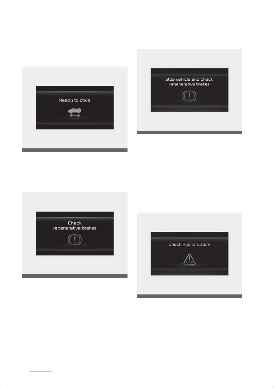
LCD display messages
Ready to start driving
This message is displayed when the
vehicle is ready to be driven.
Check regenerative brakes
This message is displayed when the
brake performance is low or the
regenerative brake does not work
properly due to a failure in the brake
system.
If this occurs, it may take longer for
the brake pedal to operate and the
braking distance may become lon
-
ger.
Stop vehicle and check brakes
This message is displayed when a
failure occurs in the brake system.
If this occurs, park the vehicle in a
safe location tow your vehicle to the
nearest authorized Kia dealer and
have the vehicle inspected.
Check Hybrid system
This message is displayed when
there is a problem with the hybrid
control system. Refrain from driving
when the warning message is dis
-
played.
OMQ4HQ010035L
OMQ4HQ010036L
OMQ4HQ010018L
OMQ4HQ010013L
29
1
1
Hybrid system overview Driving the hybrid/plug-in hybrid vehicle
If this occurs, have the vehicle
inspected by an authorized Kia
dealer.
Stop safely and check Hybrid sys
-
tem
This message is displayed when
there is a problem with the hybrid
control system. The ( ) indicator
will blink and a warning chime will
sound until the problem is solved.
Refrain from driving when the
warning message is displayed.
If this occurs, have the vehicle
inspected by an authorized Kia
dealer.
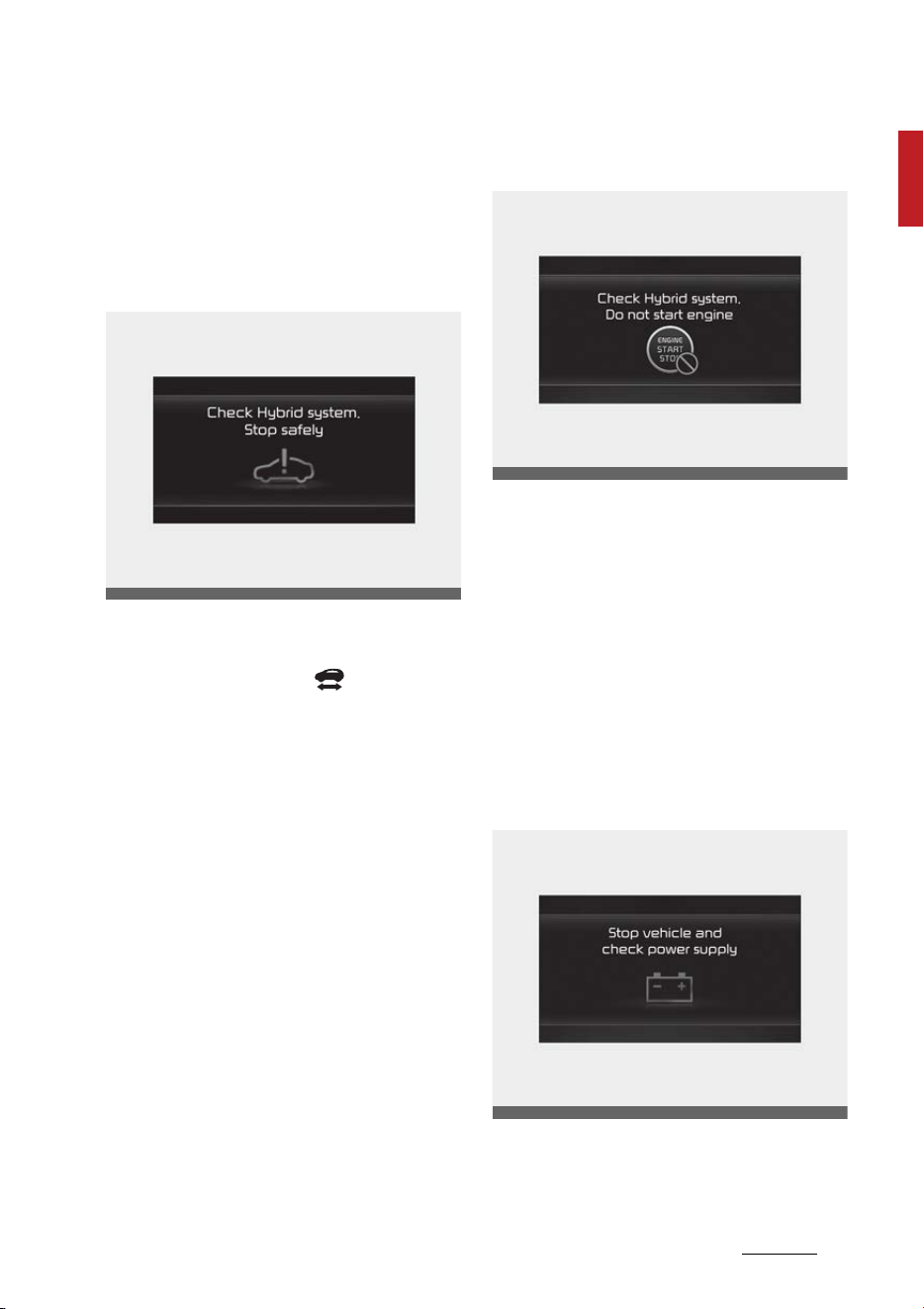
Check Hybrid system. Do not start
engine
This message is displayed when the
hybrid battery power (SOC) level is
low. A warning chime will sound until
the problem is solved. Refrain from
driving when the warning message
is displayed.
If this occurs, have the vehicle
inspected by an authorized Kia
dealer.
Stop safely and check power supply
This message is displayed when a
failure occurs in the power supply
system.
OMQ4PH041595L
OMQ4HQ010015L
OMQ4HQ010016L
Hybrid system overview
301
Driving the hybrid/plug-in hybrid vehicle
If this occurs, park the vehicle in a
safe location and tow your vehicle
to the nearest authorized Kia dealer
and have the vehicle inspected.
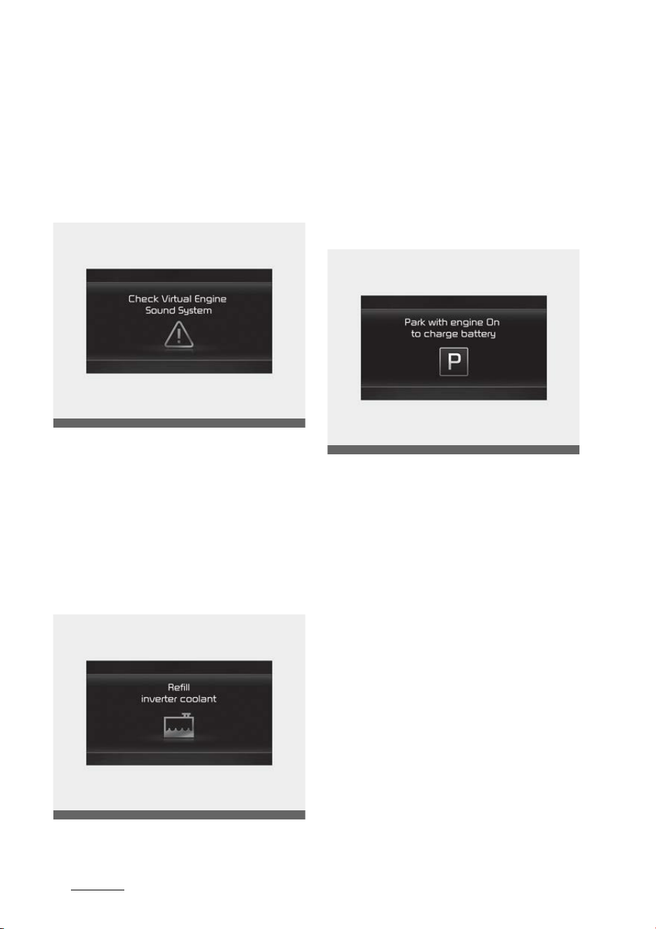
Check Virtual Engine Sound System
This message is displayed when
there is a problem with the Virtual
Engine Sound System (VESS).
If this occurs, have the vehicle
inspected by an authorized Kia
dealer.
Refill inverter coolant
This message is displayed when the
inverter coolant is nearly empty.
You should refill the inverter cool
-
ant.
Park with engine On to charge bat
-
tery
This message is displayed when the
hybrid battery power (SOC) level is
low.
If this occurs, park the vehicle in a
safe location and wait until the
hybrid battery is charged.
OMQ4HQ010012L
OMQ4HQ010017L
OMQ4HQ010020L
31
1
1
Hybrid system overview Driving the hybrid/plug-in hybrid vehicle
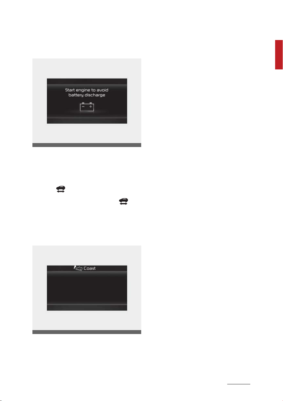
Start engine to avoid battery dis
-
charge
This message is displayed to inform
the driver the 12V battery may be
discharged if the ENGINE START/
STOP button is in ON position (with
-
out the indicator ON).
Set the vehicle to the ready ( )
mode to prevent the 12V battery
from being discharged.
Coasting guide (if equipped)
A chime will sound and the coasting
guide indicator will be displayed to
inform the driver when to take the
foot off the accelerator by antici
-
pating a decelerating event* based
on the analysis of driving routes and
road conditions stored in the navi
-
gation system. It encourages the
driver to remove the foot from the
pedal and allow coasting down the
road with EV motor only. This helps
preventing unnecessary fuel con
-
sumption and increases fuel effi
-
ciency.
* Example of a deceleration event is
going down an extended hill, slow
-
ing down approaching a toll booth,
and approaching reduced speed
zones.
䳜 User settings
Press the ENGINE START/STOP
button and put the shift dial in P
(Park). In the User Settings Mode,
select Driver assistance, Coasting
Guide, and then On to turn on the
system. Cancel the selection of
coasting guide to turn off the
system. For the explanation of
the system, press and hold the
[OK] button.
䳜 Operation conditions
To activate the system, take the
following procedures. Enter your
destination information on the
navigation and select the driving
route. Select the ECO mode in the
Integrated Driving Control Sys
-
tem. Then, satisfy the following:
- The driving speed should be
between 19 mph (30 km/h) and
99 mph (160 km/h).
OMQ4HQ010022L
OMQ4PH050357L
Hybrid system overview
321
Driving the hybrid/plug-in hybrid vehicle
* The operating speed may vary due
to difference between instrument
cluster and navigation effected by
tire inflation level.
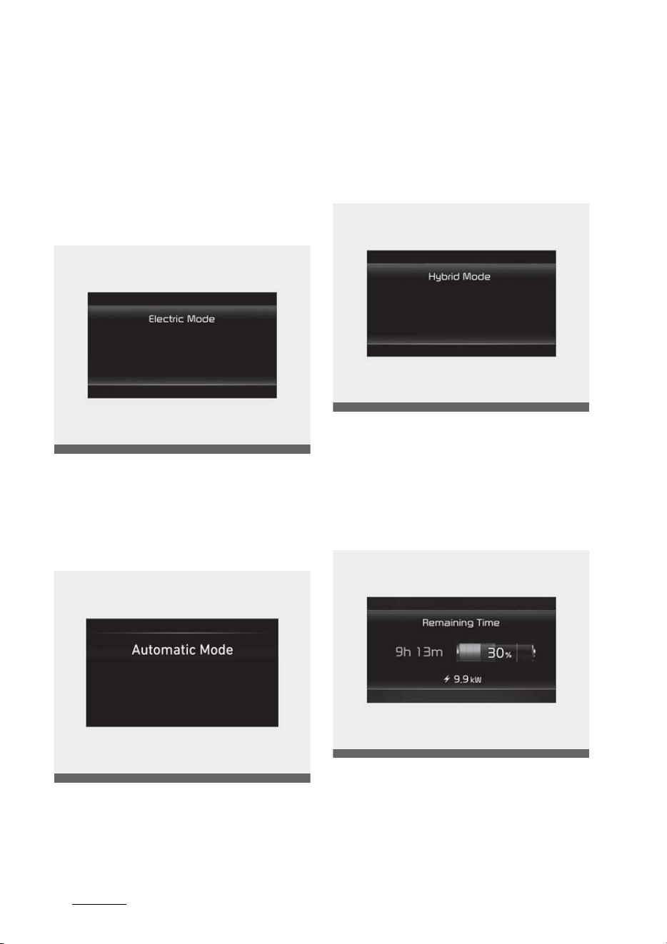
CD (Charge Depleting, Electric)
mode (Plug-in hybrid vehicle)
The high-voltage (hybrid) battery is
used to drive the vehicle.
AUTO (Automatic) mode (Plug-in
hybrid vehicle)
The drive mode will be automatically
selected from either Electric (CD)
mode or Hybrid (CS) mode by the
system according to the driving
condition.
CS (Charge Sustaining, Hybrid)
mode (Plug-in hybrid vehicle)
The high-voltage (hybrid) battery
and gasoline engine is used to drive
the vehicle.
Remaining charge time (Plug-in
hybrid vehicle)
The message is displayed to notify
the remaining time to fully charge
the battery.
OMQ4PH050364L
OMQ4PH050360L
OMQ4PH050366L
OMQ4PHQ010048L

33
1
1
Hybrid system overview Driving the hybrid/plug-in hybrid vehicle
Charging stopped. Check the AC
charger (Plug-in hybrid vehicle)
This messages is displayed when
the charging failed by external char
-
ger error.
The purpose of this message is to
let you know the error has occurred
in the charger itself, not in the vehi
-
cle.
Charging stopped. Check the cable
connection (Plug-in hybrid vehicle)
This messages is displayed when
charging is stopped because the
charging connector is not correctly
connected to the charging inlet. If
this occur, separate the charging
connector and re-connect it and
check whether there is any problem
(external damage, foreign sub
-
stances, etc.) with the charging con
-
nector and charging inlet. If the
same problem occurs when charging
the vehicle with a replaced charging
cable or genuine Kia portable char
-
ger, have the vehicle inspected by a
professional workshop. Kia recom
-
mends to visit an authorized Kia
dealer/service partner.
Low/High System Temp. Maintain
-
ing Hybrid mode (Plug-in hybrid
vehicle)
This message is displayed when the
temperature of the high-voltage
(hybrid) battery is too low or too
high.
This warning message is to protect
the battery and the hybrid system.
Low/High System Temp. Switching
to Hybrid mode (Plug-in hybrid
vehicle)
This message is displayed when the
temperature of the high-voltage
(hybrid) battery is too low or high.
This warning message is to protect
the battery and the hybrid system.
Switching to Hybrid mode to allow
heating (Plug-in hybrid vehicle)
䳜 When the outdoor temperature is
lower than 5 F (-15 C) and the
coolant temperature is lower than
158 F (70 C), you turn the cli
-
mate control On for heating, the
above message will be displayed
in the cluster. Then, the vehicle
will automatically switch to HEV
mode and EV mode will not be
activated (although EV/HEV but
-
ton is pressed)
䳜 When the outdoor temperature is
higher than 14 F (-10 C), or the
coolant temperature is higher
than 176 F (80 C) or you turn
the climate control Off, the vehi
-
cle will automatically return to EV
mode.

Hybrid system overview
341
Driving the hybrid/plug-in hybrid vehicle
Wait until fuel door unlocks (Plug-in
hybrid vehicle)
The message is displayed when you
attempt to unlock the fuel filler door
with the fuel tank pressurized. Wait
until the fuel tank is depressurized.
NOTICE
䳜 It may take up to 20 seconds to
unlock fuel filler door.
䳜 If the fuel filler door does not
open because ice has formed
around it, tap lightly or push on
the door to break the ice and
release the door.
䳜 Do not pry on the door. If neces
-
sary, spray around the door with
an approved de-icer fluid (do not
use radiator anti-freeze) or move
the vehicle to a warm place and
allow the ice to melt.
Fuel door unlocked (Plug-in hybrid
vehicle)
This message is displayed when the
fuel filler door is unlocked.
Also means "Ready to refuel".
Please press the rear center edge of
fuel filler door to open.
Check fuel door (Plug-in hybrid
vehicle)
This message is displayed when the
fuel filler door is open while driving
or an abnormality has occurred.
Charging door open (Plug-in hybrid
vehicle)
This message indicates that the
charging door is open while in driving
ready state to encourage you to
inspect and close the door.
(Driving with the charging door open
may result in moisture inflow or
damage. This message is used to
prevent such occurrences.)
Unplug vehicle to start (Plug-in
hybrid vehicle)
The message is displayed when you
start the engine without unplugging
the charging cable. Unplug the
charging cable, and then start the
vehicle.
Maintaining Hybrid mode to con
-
tinue heating (Plug-in hybrid vehi
-
cle)
A message is displayed when heat
-
ing is in operation and the HEV
mode is maintained to meet the
heating operating conditions when
attempting to switch to EV mode by
pressing the EV/HEV button.
EV/HEV modes (Plug-in hybrid
vehicle)
A corresponding message is dis-
played when a mode is selected by
pressing the EV/HEV button.
35
1
1
Hybrid system overview Driving the hybrid/plug-in hybrid vehicle
PHEV infotainment system (Plug-
in hybrid vehicle)
Press [PHEV] on the [Home screen].
The Plug-in Hybrid menu consists of
five sections: [EV range], [Energy
information], [Charge manage
-
ment], [ECO driving], [Energy flow].
For more information, please refer
to the infotainment manual that
was separately supplied with your
vehicle.
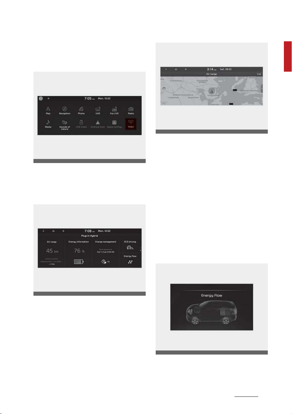
Energy flow
The hybrid system informs the driv
-
ers its energy flow in various oper
-
ating modes. During driving, the
current energy flow is specified in
11 modes.
Vehicle stop
The vehicle is stopped.
(No energy flow)
OMQ4PH040493L
OMQ4PH040492L
OMQ4PH040491L
OMQ4HQ010002L
Hybrid system overview
361
Driving the hybrid/plug-in hybrid vehicle
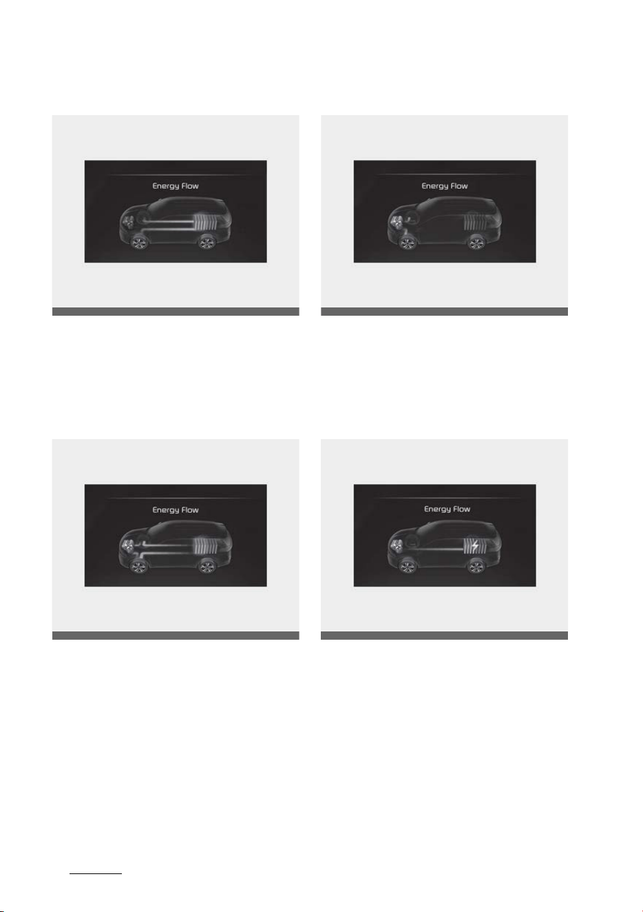
EV propulsion
Only the motor power is used to
drive the vehicle.
(Battery → Wheel)
Power assist
Both the motor and the engine
power are used to drive the vehicle.
(Battery & Engine → Wheel)
Engine only propulsion
Only the engine power is used to
drive the vehicle.
(Engine → Wheel)
Engine generation
When the vehicle is stopped, the
high-voltage battery is charged up
by the engine.
(Engine → Battery)
OMQ4HQ010003L
OMQ4HQ010004L
OMQ4HQ010005L
OMQ4PH041596L
37
1
1
Hybrid system overview Driving the hybrid/plug-in hybrid vehicle
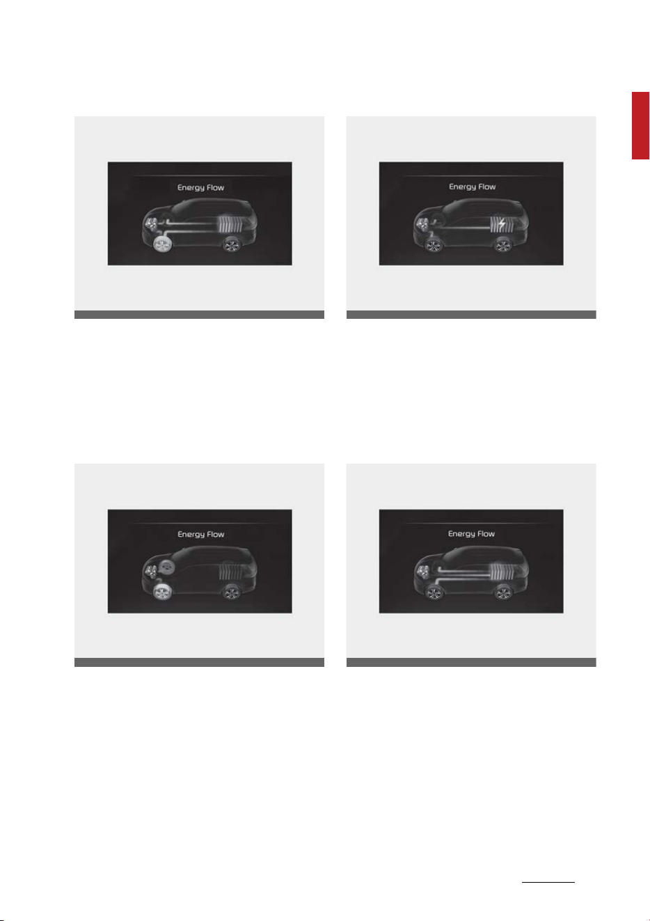
Regeneration
The high-voltage battery is charged
up by the regenerative brake sys
-
tem.
(Wheel → Battery)
Engine brake
The engine braking is used to decel
-
erate the vehicle.
(Wheel → Engine)
Power reserve
The engine is simultaneously used
to drive the vehicle and to charge up
the high-voltage battery.
(Engine → Wheel & Battery)
Engine generation/motor drive
The engine charges up the high-
voltage battery. The motor power is
used to drive the vehicle.
(Engine → Battery → Wheel)
OMQ4HQ010030L
OMQ4HQ010007L
OMQ4PH041597L
OMQ4HQ010009L
Hybrid system overview
381
Driving the hybrid/plug-in hybrid vehicle
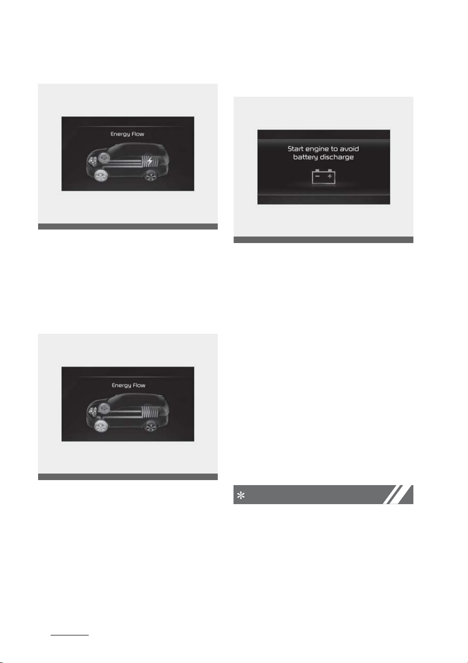
Engine generation/regeneration
The engine and regenerative brake
system charges up the high-voltage
battery.
(Engine & Wheel → Battery)
Engine brake/regeneration
The engine braking is simultane
-
ously used to decelerate the vehicle
and to charge up the high-voltage
battery.
(Wheel → Engine & Battery)
Start engine to avoid battery dis
-
charge
If the engine is not turned on with
the ENGINE START/STOP button in
ACC or ON for a while, the battery
can be discharged. Please turn on
the engine to prevent 12V battery
from discharge.
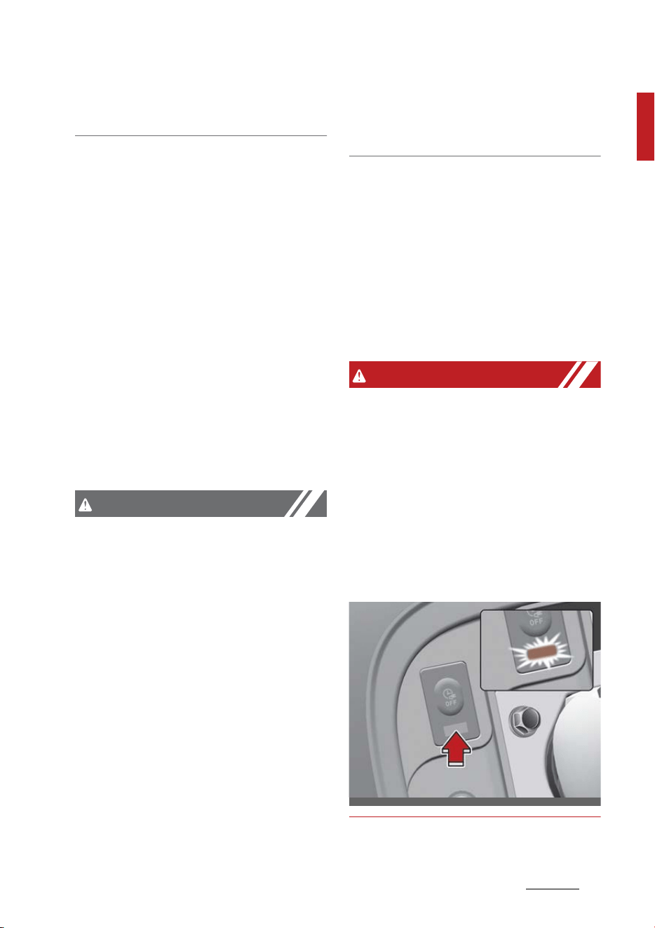
Aux. Battery Saver+ (Plug-in hybrid
vehicle)
The Aux. Battery Saver+ is a func
-
tion that monitors the charging sta
-
tus of the 12V auxiliary battery. If
the auxiliary battery level is low, the
main high voltage battery charges
the auxiliary battery.
NOTICE
The Aux. Battery Saver+ function
will be ON when the vehicle is deliv
-
ered. If the function is not needed,
you may turn it off in the Users
Settings mode on the LCD display.
For more information, refer to the
OMQ4PH041598L
OMQ4HQ010011L
OMQ4HQ010022L
39
1
1
Hybrid system overview Driving the hybrid/plug-in hybrid vehicle
"System setting" on the following
page.
Mode
䳜 Cycle Mode: When the vehicle is
OFF with all doors, hood and tail
-
gate closed, the Aux. Battery
Saver+ periodically activates
according to the auxiliary battery
status.
䳜 Automatic Mode: When the
ENGINE START/STOP button is in
the ON position with the charging
connector plugged in, the function
activates according to the auxil
-
iary battery status to prevent
over-discharge of the auxiliary
battery.
CAUTION
䳜 The Aux. Battery Saver+ activates
for a maximum of 20 minutes. If
the Aux. Battery Saver+ function
activates more than 10 times
consecutively, in the Automatic
Mode the function will stop acti
-
vating, judging that there is a
problem with the auxiliary bat
-
tery. In this case, drive the vehicle
for some period of time. The
function will start activating if the
auxiliary battery returns to nor
-
mal.
䳜 The Aux. Battery Saver+ function
cannot prevent battery discharge
if the auxiliary battery is dam
-
aged, worn out, used as a power
supply or unauthorized electronic
devices are used.
System setting
The driver can activate the Aux.
Battery Saver+ function by placing
the ENGINE START/STOP button to
the ON position and by selecting:
"User Settings → Other Features →
Aux. Battery Saver+"
WARNING
When the function is activating the
charging indicator lamp will quickly
blink and high voltage electricity will
be flowing in the vehicle. Do not touch
the high voltage electric wire (orange),
connector, and all electric components
and devices. This may cause electric
shock and lead to injuries. Also, do not
modify your vehicle in any way. This
may affect your vehicle performance
and lead to an accident.
OMQ4PH010016L
Hybrid system overview
401
Components of the hybrid/plug-in hybrid vehicle
Components of the hybrid/plug-in hybrid vehicle
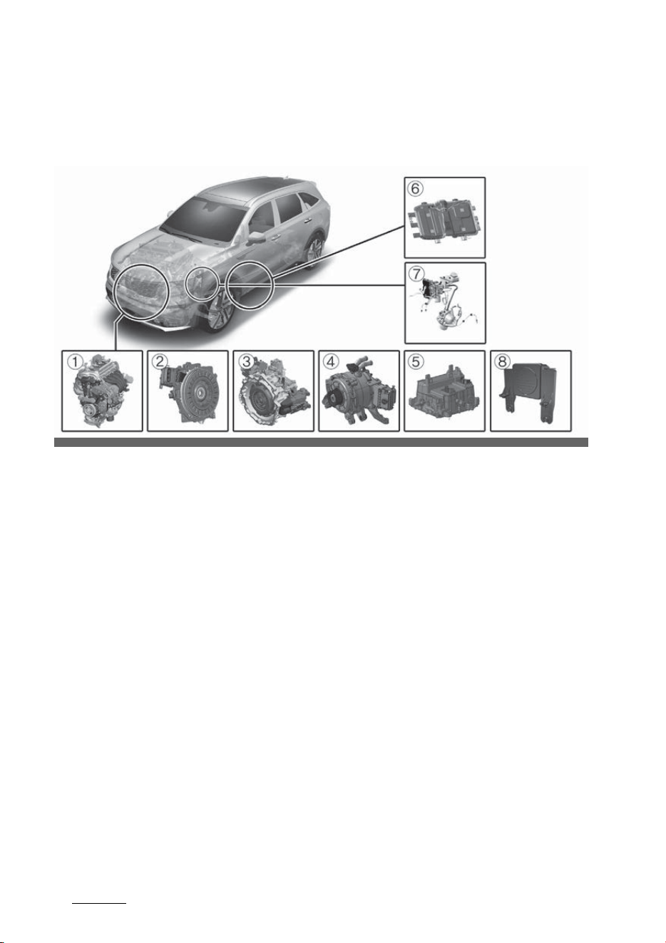
Plug-in hybrid vehicle components
* The actual shape may differ from the illustration.
1. Engine: 1.6L
2. Motor: 66.9kW
3. Transmission: 6AT
4. Hybrid starter generator (HSG)
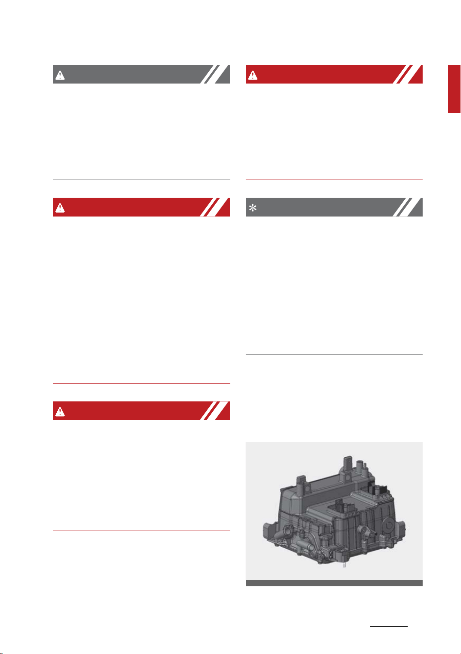
5. HPCU (Hybrid Power Control Unit)
6. High voltage battery system
7. Regenerative brake system
8. Virtual Engine Sound System (VESS)
The Hybrid battery uses high voltage to operate the electric motor and
other components. High voltage is dangerous if touched.
Your vehicle is equipped with orange colored insulation and covers over the
high voltage components to protect people from electric shock. High voltage
warning labels are attached to some system components as additional
warnings. Have your vehicle serviced by an authorized Kia dealer.
OMQ4PHQ010047L
41
1
1
Hybrid system overview Components of the hybrid/plug-in hybrid vehicle
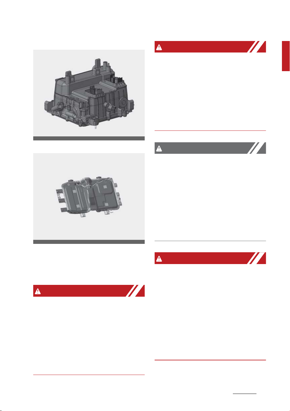
HPCU (Hybrid Power Control Unit) *1
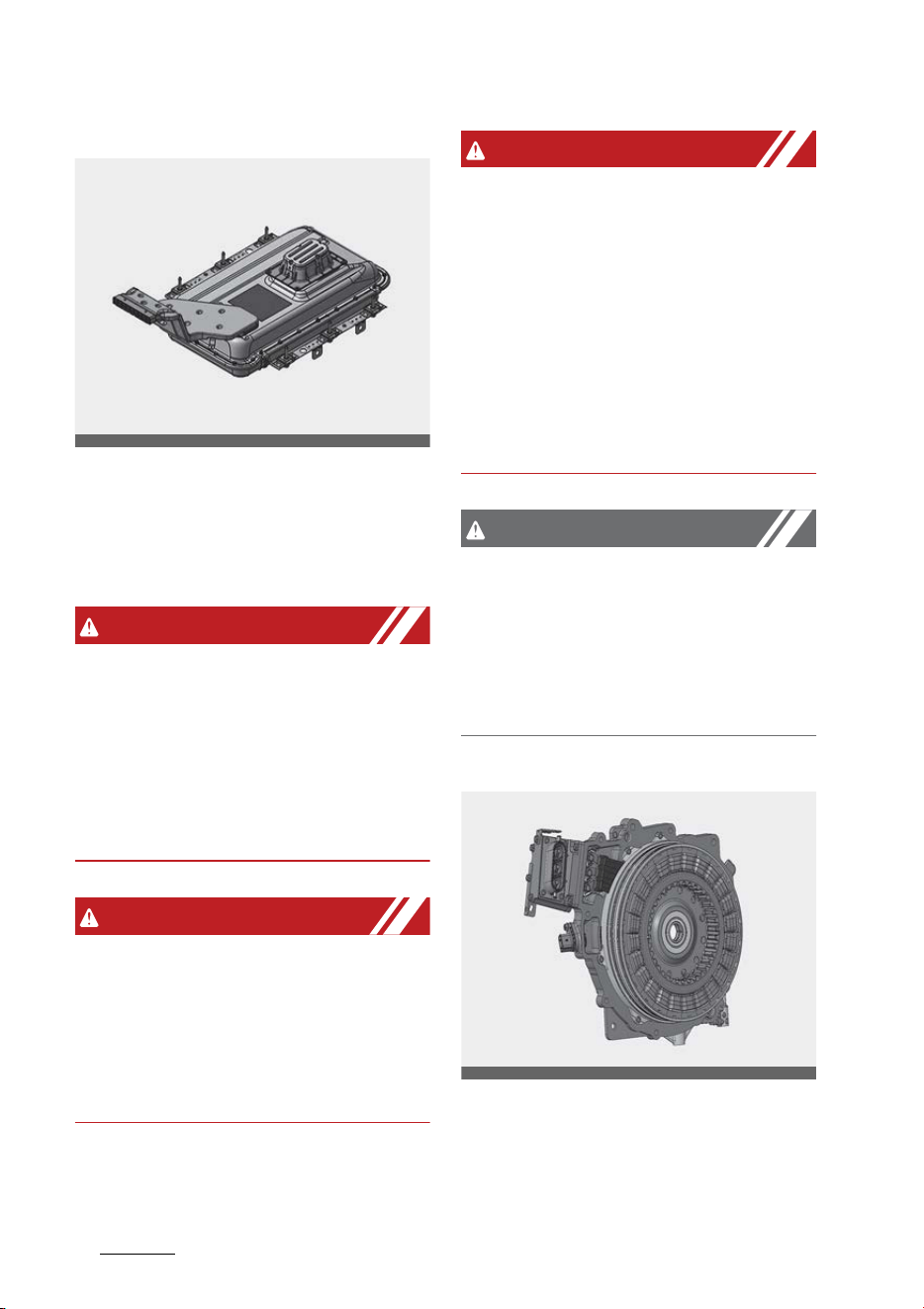
High voltage battery system *2
* 1: Located in the engine compart
-
ment
* 2: Located under the 1st row seats
WARNING
High voltage components
Never touch orange colored or high
voltage labeled components, includ
-
ing wires, cables, and connections.
When the insulators or covers are
damaged or removed, severe injury
or death from electrocution may
occur.
WARNING
Avoid Touching Hybrid Power Con
-
trol Unit
While replacing the fuses in the
engine compartment, never touch
the HPCU. The HPCU carries high
voltage. Touching the HPCU may
result in electrocution, serious
injury, or death.
CAUTION
High Voltage Battery Damage
When loading your vehicle, be care
-
ful of transporting items in a man
-
ner that could damage the high
voltage battery. Do not store items
on top of the high voltage battery or
overload the trunk area. Such
actions may ultimately damage the
high voltage battery unit.
WARNING
In the hybrid system, the hybrid
battery uses high voltage to oper
-
ate the motor and other compo
-
nents. This high voltage hybrid
battery system can be very danger
-
ous.
Never touch the hybrid system.
When you touch the hybrid battery
system, serious injury or death may
occur.
OMQ4HQ010034
OMQ4PH010013L
Hybrid system overview
421
Components of the hybrid/plug-in hybrid vehicle
CAUTION
䳜 Be careful when loading flamma
-
ble liquid in the passenger com
-
partment. It could cause
operational and safety degrada
-
tion if the liquid leaks and flows in
the high voltage battery.
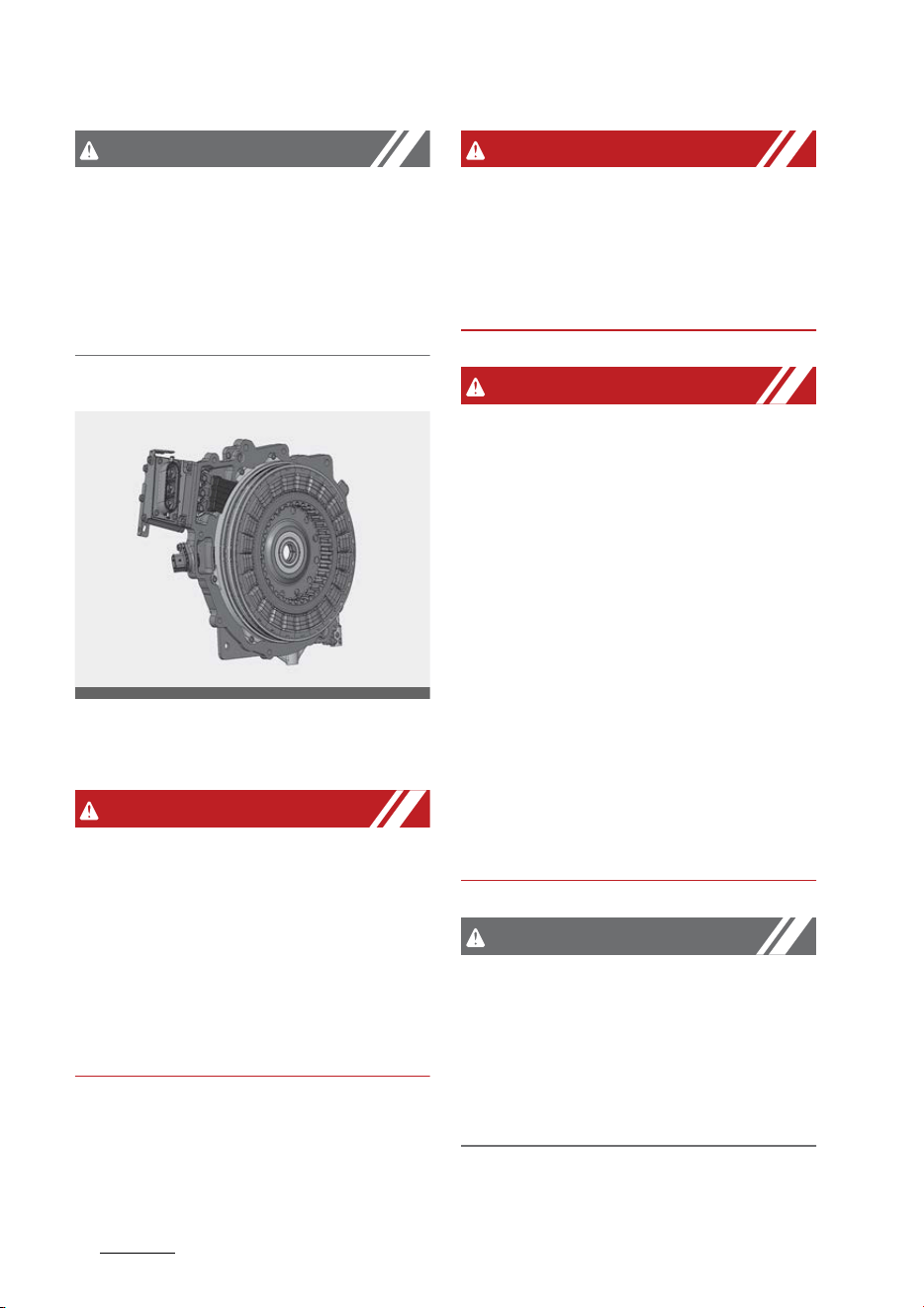
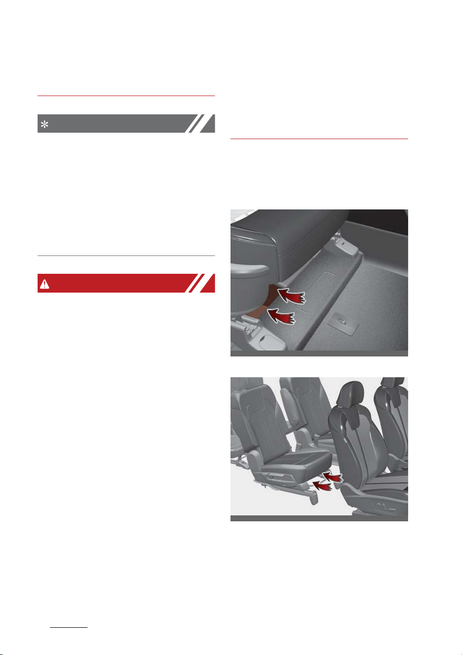
Drive motor *3
* 3: Located in the engine compart
-
ment
WARNING
Battery electrolyte
As with all batteries, avoid fluid con
-
tact with the hybrid battery. If the
battery is damaged and if electro
-
lyte comes in contact with your
body, clothes or eyes, immediately
flush with a large quantity of fresh
water and seek medical attention.
WARNING
After market battery charger
Do not use an after-market battery
charger to charge the hybrid bat
-
tery. Doing so may result in death or
serious injury.
WARNING
High waters
䳜 Avoid high waters as this may
result in your vehicle becoming
saturated with water and could
compromise the high voltage
components.
䳜 Do not touch the any of the high
voltage components within your
vehicle if your vehicle has been
submerged in water equal to half
of the vehicle height. Touching
high voltage components once
submerged in water could result
in severe burns or electric shock
that could result in death or seri
-
ous injury.
CAUTION
Carrying liquids in tailgate
Do not load large amounts of water
in open containers into the vehicle. If
the water spills onto the HEV bat
-
tery, it may cause a short and dam
-
age the battery.
OMQ4HQ010033
43
1
1
Hybrid system overview Components of the hybrid/plug-in hybrid vehicle
CAUTION
Cleaning engine
When you clean the engine com
-
partment, do not wash using water.
Water may cause electric arcing to
occur and damage electronic parts
and components.
WARNING
Exposure to high voltage
䳜 High voltage in the hybrid battery
system is very dangerous and can
cause severe burns and electric
shock. This may result in serious
injury or death.
䳜 For your safety, never touch,
replace, dismantle or remove any
portion of the hybrid battery sys
-
tem including components, cables
and connectors.
WARNING
Use of water or liquids
If water or liquids come into contact
with the hybrid system compo
-
nents, and you are also in contact
with the water, severe injury or
death due to electrocution may
occur.
WARNING
Hot components
When the hybrid battery system
operates, the HEV battery system
can be hot. Heat burns may result
from touching even insulated com
-
ponents of the HEV system.
NOTICE
Prolonged parking
Prolonged parking might cause bat
-
tery discharge and operation failure
due to natural discharge. Driving the
vehicle approximately once every 2
months, more than 9 miles (15 km)
is recommended.The battery will be
charged automatically when driving
the vehicle.
Hybrid vehicle components
High voltage battery system
HPCU (Hybrid Power Control Unit) *1
OMQ4HQ010034
Hybrid system overview
441
Components of the hybrid/plug-in hybrid vehicle
High voltage battery system *2
* 1: Located in the engine compart
-
ment
* 2: Located under the passenger
side seat floor
WARNING
Never touch orange colored or high
voltage labeled components, includ
-
ing wires, cables, and connections.
When the insulators or covers are
damaged or removed, severe injury
or death from electrocution may
occur.
WARNING
While replacing the fuses in the
engine compartment, never touch
the HPCU. The HPCU carries high
voltage. Touching the HPCU may
result in electrocution, serious
injury, or death.
WARNING
In the hybrid system, the hybrid
battery uses high voltage to oper
-
ate the motor and other compo
-
nents. This high voltage hybrid
battery system can be very danger
-
ous.
Never touch the hybrid system.
When you touch the hybrid battery
system, serious injury or death may
occur.
CAUTION
䳜 Be careful when loading flamma
-
ble liquid in the passenger side
seat floor. It could cause opera
-
tional and safety degradation if
the liquid leaks and flows in the
high voltage battery.
Drive motor *3
* 3: Located in the engine compart
-
ment
OMQ4HQ010032
OMQ4HQ010033

45
1
1
Hybrid system overview Components of the hybrid/plug-in hybrid vehicle
WARNING
䳜 Do not disassemble the high volt
-
age motor connector. The high
voltage motor connector may
contain residual high voltage.
Coming in contact with high volt
-
age may result in death or serious
injury.
䳜 Your vehicle's hybrid system
should only be inspected or
repaired by an authorized Kia
dealer.
WARNING
䳜 Do not disassemble or assemble
the high voltage battery system.
Doing so may result in electric
shock, causing death or serious
injury.
䳜 If you disassemble or assemble
hybrid system components
improperly, it may damage the
performance and reliability of
your vehicle.
䳜 If electrolyte comes in contact
with your body, clothes or eyes,
immediately flush with a large
quantity of fresh tap water. Have
your eyes examined by a doctor
as soon as possible.
WARNING
Never assemble or disassemble the
high voltage battery system.
䳜 If you assemble or disassemble
the high voltage battery system,
the durability and performance of
the vehicle may be damaged.
䳜 When you want to check the high
voltage battery system, have the
vehicle inspected by an authorized
Kia dealer.
䳜 Do not touch the high voltage
battery and high voltage cable
connected to motor (orange
color). Severe burns and electric
shock may occur. For your safety,
do not touch the cover of elec
-
tronic components and electronic
cable. Do not remove the cover of
electronic components and elec
-
tronic cable. In particular, never
touch the high voltage battery
system when the hybrid system
in operation. It may result in
death or serious injury.
WARNING
䳜 Never use the package modules
(high voltage battery, inverter
and converter) for any other pur
-
pose.
䳜 Do not use an unauthorized bat
-
tery charger to charge the high
voltage battery. Doing so may
result in death or serious injury.
䳜 Never locate the high voltage sys
-
tem near or in a fire.
䳜 Never drill into or strike the pack
-
age module. Otherwise, it may be
damaged. An electric shock may
Hybrid system overview
461
Components of the hybrid/plug-in hybrid vehicle
occur, resulting in serious injury or
death.
NOTICE
䳜 When the vehicle is paint baked,
do not bake over 30 minutes in
158F (70C) or 20 minutes in
176F (80C) degree.
䳜 Do not wash the engine compart
-
ment, using water. Water may
cause an electric shock and dam
-
age the electronic components.
WARNING
This hybrid vehicle uses the hybrid
battery system inverter and con
-
verter to generate high voltage.
High voltage in the hybrid battery
system is very dangerous and may
cause severe burns and electric
shock. This may result in serious
injury or death.
䳜 For your safety, never touch,
replace, disassemble or remove
the hybrid battery system includ
-
ing components, cables and con
-
nectors. Severe burns or electric
shock may result in serious injury
or death when you fail to follow
this warning.
䳜 When the hybrid battery system
operates, the hybrid battery sys
-
tem can be hot. Always be careful
because burns or electric shock
may be caused by high voltage.
䳜 Do not spill liquid on the HPCU,
HSG, motor and fuses. If the
hybrid system components come
in contact with liquid, it may
result in electric shock.
Hybrid battery cooling duct (Hybrid
vehicle)
Inlet duct
Outlet duct
The hybrid battery cooling duct is
located below the right side of the
front seats. The cooling duct cools
down the hybrid battery. When the
hybrid battery cooling duct is
OMQ4AH080007
OMQ4081009N
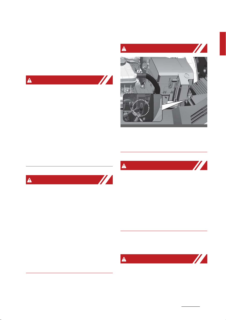
47
1
1
Hybrid system overview Components of the hybrid/plug-in hybrid vehicle
blocked, the hybrid battery may be
overheated.
Clean the cooling duct for the hybrid
battery with a dry cloth on a regular
basis.
WARNING
Air Intake
䳜 Blocking the air intake behind the
rear seats may damage the HEV
battery.
䳜 Do not allow any water into the
air intake even when cleaning. If
any water enters the air intake,
the Hybrid battery may cause an
electric shock which can cause
serious injury or death due to
electrocution.
WARNING
Interference with electronic medical
devices
Electromagnetic waves that are
generated from the charger can
impact medical electric devices such
as an implantable cardiac pace
-
maker. When using such medical
electric devices, ask your medical
professional and the device manu
-
facturer whether charging your
electric vehicle will impact the oper
-
ation of the medical electric devices.
Service interlock connector
WARNING
In case of emergency, cut the ser
-
vice interlock connector cable to iso
-
late the high voltage of the battery.
WARNING
Service interlock connector
Never touch the safety plug. The
safety plug is attached to the high
voltage hybrid battery system.
Touching the safety plug may result
in death. Service personnel should
follow the appropriate procedures in
the service manual.
If an accident occurs
WARNING
䳜 For your safety, do not touch the
high voltage cables, connectors
and package modules. High volt
-
OMQ4H070020

Hybrid system overview
481
Components of the hybrid/plug-in hybrid vehicle
age components are orange in
color.
䳜 Exposed cables or wires may be
visible inside or outside of the
vehicle. Never touch the wires or
cables, because an electrical
shock, an injury, or a death may
occur.
䳜 Any gas or electrolyte leakage
from your vehicle is not only poi
-
sonous but also flammable. Upon
witnessing one of those, open the
windows, and remain a safe dis
-
tance from the vehicle out of the
road.
Immediately call an emergency
services or contact an authorized
Kia dealer and advise them that a
hybrid vehicle is involved.
䳜 When the vehicle is severely dam
-
aged, remain a safe distance of
49 ft. (15 m) or more between
your vehicle and other vehicles/
flammables.
NOTICE
If a fire occurs:
䳜 If a small scale fire occurs, use a
fire extinguisher (ABC, BC) that is
meant for electrical fires.
If it is impossible to extinguish the
fire in the early stage, remain a
safe distance from the vehicle and
immediately call your local fire
emergency responders. Also,
advise them that a hybrid vehicle
is involved.
If the fire spreads to the high
voltage battery, large amount of
water is needed to put out the
fire.
Using small amount of water or
fire extinguishers not meant for
electrical fires could cause serious
injury or death from electrical
shocks.
䳜 Upon witnessing any sparks,
gases, flames, or fuel leakage of
your vehicle, immediately call
emergency services or contact an
authorized Kia dealer. Also, advise
them that a hybrid vehicle is
involved.
WARNING
When a submersion in water occurs:
When your vehicle is flooded in
water, a high-voltage battery may
cause shock or fires. Thus, turn the
hybrid system OFF, take the key in
your possession and escape to a
safe place. Never attempt physical
contact with your flooded vehicle.
Immediately contact an authorized
Kia dealer and advise them that a
hybrid vehicle is involved.
When the hybrid vehicle shuts off
When the high voltage battery or 12
volt battery is discharged, or when

49
1
1
Hybrid system overview Components of the hybrid/plug-in hybrid vehicle
the fuel tank is empty, the hybrid
system may not operate while driv
-
ing. When the Hybrid system does
not operate, do the followings:
1. Gradually reduce the vehicle
speed. Pull over your vehicle off
the road in a safe area.
2. Locate the shift dial in P (Park).
3. Turn ON the hazard warning
flashers.
4. Turn OFF the vehicle, and try to
start the hybrid system again,
while depressing the brake pedal
and turning on the ENGINE
START/STOP button.
5. When the hybrid system still does
not operate, refer to "Emergency
starting" on page 7-5.
Before jump-starting the vehicle,
check the fuel level and the exact
procedure to jump start. When
the fuel level is low, do not
attempt to drive the vehicle only
with the battery power. The high
voltage battery may be dis
-
charged, and the hybrid system
will turn OFF.
WARNING
Vehicle accident
Never touch electric wires or cable.
If exposed electric wires or cables
are visible inside or outside of your
vehicle, an electric shock may occur.
WARNING
Putting out fire
Never use a small quantity of water
to put out a fire in your vehicle. If a
fire occurs, evacuate the car imme
-
diately and contact the fire depart
-
ment.


2Introduction
Introduction
Fuel requirements .................................................................... 2-2
Vehicle modifications ............................................................... 2-4
Vehicle break-in process ......................................................... 2-5
Risk of burns when parking or stopping vehicle..................2-5
Vehicle handling instructions .................................................. 2-6
Vehicle data collection and Event Data Recorders.............. 2-6
HEV/PHEV powertrain ............................................................. 2-7

Introduction
22
Fuel requirements
Introduction
Fuel requirements
Your new vehicle is designed to use
only unleaded fuel having a pump
octane number ((R+M)/2) of 87
(Research Octane Number 91) or
higher. (Do not use methanol blend-
ed fuels.)
Your new vehicle is designed to
obtain maximum performance with
UNLEADED FUEL, as well as mini-
mize exhaust emissions and spark
plug fouling.
Never add any fuel system cleaning
agents to the fuel tank other than
what has been specified. (Consult an
authorized Kia dealer for details.)
䳜 Tighten the cap until it clicks one
time, otherwise the Check Engine
light will illuminate.
WARNING
Refueling
䳜 Do not "top off" after the nozzle
automatically shuts off. Attempts
to force more fuel into the tank
can cause fuel overflow onto you
and the ground, causing a risk of
fire.
䳜 Always check that the fuel cap is
installed securely to prevent fuel
spillage, especially in the event of
an accident.
Gasoline containing alcohol and
methanol
Gasohol, a mixture of gasoline and
ethanol (also known as grain alco
-
hol), and gasoline or gasohol con
-
taining methanol (also known as
wood alcohol) are being marketed
along with or instead of leaded or
unleaded gasoline.
Pursuant to Environmental Protec
-
tion Agency (EPA) regulations, etha
-
nol may be used in your vehicle.
Do not use gasohol containing more
than 15% ethanol, and do not use
gasoline or gasohol containing any
methanol. Ethanol provides less
energy than gasoline and attracts
water. Thus, it is likely to reduce
your fuel efficiency and could lower
your MPG results.
Methanol may cause drivability
problems and damage to the fuel
system, engine control system and
emission control system.
Discontinue using gasohol of any
kind if drivability problems occur.
Vehicle damage or drivability prob
-
lems may not be covered by the
manufacturer's warranty if they
result from the use of:
1. Gasoline or gasohol containing
methanol.
2. Leaded fuel or leaded gasohol.
3. Gasohol containing more than
15% ethanol.

3
2
2
Introduction Fuel requirements
"E85" fuel is an alternative fuel
comprised of 85% ethanol and 15%
gasoline, and is manufactured
exclusively for use in Flexible Fuel
Vehicles. "E85" is not compatible
with your vehicle. Use of "E85" may
result in poor engine performance
and damage to your vehicle's engine
and fuel system. Kia recommends
that customers do not use fuel with
an ethanol content exceeding 15%.
NOTICE
Your New Vehicle Limited Warranty
does not cover damage to the fuel
system or any performance prob
-
lems caused by the use of "E85"
fuel.
NOTICE
Never use any fuel containing meth
-
anol. Discontinue use of any metha
-
nol containing products which may
inhibit proper drivability.
Other fuels
Using fuels that contain Silicone (Si),
MMT (Methylcyclopentadienyl Man
-
ganese Tricarbonyl), Manganese
(Mn) contained fuel, and other
metallic additives, may cause vehicle
and engine damage or cause misfir
-
ing, poor acceleration, engine stall
-
ing, catalyst melting, clogging,
abnormal corrosion, life cycle reduc
-
tion, etc.
Also, the Malfunction Indicator Lamp
(MIL) may illuminate.
NOTICE
Damage to the fuel system or per
-
formance problems caused by the
use of these other fuels may not be
covered by your New Vehicle Limited
Warranty.
Gasoline containing MMT
Some gasoline contains harmful
manganese- based fuel additives
Such as MMT (Methylcyclopentadie
-
nyl Manganese Tricarbonyl). Kia
does not recommend the use of
gasoline containing MMT. This type
of fuel can reduce vehicle perfor
-
mance and affect your emission
control system. The Malfunction
Indicator Lamp (MIL) on the cluster
may come on.
Do not use methanol
Fuels containing methanol (wood
alcohol) should not be used in your
vehicle. This type of fuel can reduce
vehicle performance and damage
components of the fuel system,
engine control system and emission
control system.

Introduction
42
Vehicle modifications
Fuel additives
Kia recommends that you use
unleaded gasoline which has an
octane rating of RON (Research
Octane Number) 95 / AKI (Anti
Knock Index) 91 or higher (for
Europe) or Octane Rating of RON
(Research Octane Number) 91 / AKI
(Anti-Knock Index) 87 or higher
(except Europe).
For customers who do not use good
quality gasolines including fuel addi
-
tives regularly, and have problems
starting or the engine does not run
smoothly, one bottle of additives
should be added to the fuel tank at
every 15,000 km (For Europe) /
10,000 km (Except Europe).
Additives are available from a pro
-
fessional workshop along with
information on how to use them. Kia
recommends to visit an authorized
Kia dealer/service partner.
Operation in foreign countries
If you are going to drive your vehicle
in another country, be sure to:
䳜 Observe all regulations regarding
registration and insurance.
䳜 Determine that acceptable fuel is
available.
Vehicle modifications
This vehicle should not be modified.
Modification of your vehicle could
affect its performance, safety or
durability and may even violate gov
-
ernmental safety and emissions
regulations.
In addition, damage or performance
problems resulting from any modifi
-
cation may not be covered under
warranty.
䳜 If you use unauthorized electronic
devices, it may cause the vehicle
to operate abnormally, wire dam
-
age, battery discharge and fire.
For your safety, do not use unau
-
thorized electronic devices.

5
2
2
Introduction Vehicle break-in process
Vehicle break-in process
By following a few simple precau
-
tions for the first 4,000 miles (6,000
km) you may add to the perfor
-
mance, economy and life of your
vehicle.
䳜 Do not race the engine.
䳜 While driving, keep your engine
speed (rpm, or revolutions per
minute) between 2,000 rpm and
4,000 rpm.
䳜 Do not maintain a single engine
speed for long periods of time,
either fast or slow. Varying
engine speeds is needed to prop
-
erly break-in the engine.
䳜 Avoid hard stops, except in emer
-
gencies, to allow the brakes to
seat properly.
䳜 Don't tow a trailer during the first
1,200 miles (2,000 km) of opera
-
tion.
䳜 Fuel economy and engine perfor
-
mance may vary depending on
vehicle break-in process and be
stabilized after 4,000 miles (6,000
km). New engines may consume
more oil during the vehicle break-
in period.
Risk of burns when parking or
stopping vehicle
䳜 Do not park or stop the vehicle
near flammable items such as
leaves, paper, oil, and tire. Such
items placed near the exhaust
system can become a fire hazard.
䳜 When an engine idles at a high
speed with the rear side of the
vehicle touching the wall, heat of
the exhaust gas can cause discol
-
oration or fire. Keep enough space
between the rear part of the
vehicle and the wall.
䳜 Be sure not to touch the exhaust/
catalytic systems while engine is
running or right after the engine
is turned off. There is a risk of
burns since the systems are
extremely hot.

Introduction
62
Vehicle handling instructions
Vehicle handling instructions
As with other vehicles of this type,
failure to operate this vehicle cor
-
rectly may result in loss of control,
an accident or vehicle rollover.
Specific design characteristics
(higher ground clearance, track,
etc.) give this vehicle a higher center
of gravity than other types of vehi
-
cles. In other words they are not
designed for cornering at the same
speeds as conventional 2-wheel
drive vehicles.
Avoid sharp turns or abrupt maneu
-
vers. Again, failure to operate this
vehicle correctly may result in loss
of control, an accident or vehicle
rollover.
Be sure to read the "Reducing the
risk of a rollover" on page 6-215.
Vehicle data collection and Event
Data Recorders
This vehicle is equipped with an
Event Data Recorder (EDR). The
main purpose of an EDR is to record,
in certain crash or near crash-like
situations, such as an air bag
deployment or hitting a road obsta
-
cle, data that will assist in under
-
standing how a vehicle's systems
performed. The EDR is designed to
record data related to vehicle
dynamics and safety systems for a
short period of time, typically 30
seconds or less. The EDR in this
vehicle is designed to record such
data as:
䳜 How various systems in your
vehicle were operating;
䳜 Whether or not the driver and
passenger safety belts were
buckled/fastened;
䳜 How far (if at all) the driver was
depressing the accelerator and/or
brake pedal; and,
䳜 How fast the vehicle was travel
-
ing.
These data can help provide a bet
-
ter understanding of the circum
-
stances in which crashes and
injuries occur. NOTE: EDR data are
recorded by your vehicle only if a
non-trivial crash situation occurs;
no data are recorded by the EDR
under normal driving conditions and
no personal data (e.g., name, gen
-

7
2
2
Introduction HEV/PHEV powertrain
der, age, and crash location) are
recorded. However, other parties,
such as law enforcement, could
combine the EDR data with the type
of personally identifying data rou
-
tinely acquired during a crash inves
-
tigation.
To read data recorded by an EDR,
special equipment is required, and
access to the vehicle or the EDR is
needed. In addition to the vehicle
manufacturer, other parties, such
as law enforcement, that have the
special equipment, can read the
information if they have access to
the vehicle or the EDR.
HEV/PHEV powertrain
By following a few simple precau
-
tions for the first 600 miles (1,000
km) you may increase the perfor
-
mance economy and life of your
vehicle.
䳜 Do not race the engine.
䳜 Avoid hard stops, except in emer
-
gencies, to allow the brakes to
seat properly.


3Your vehicle at a glance
Your vehicle at a glance
Exterior overview...................................................................... 3-2
Interior overview....................................................................... 3-5
Instrument panel overview ..................................................... 3-7
Engine compartment ............................................................... 3-9
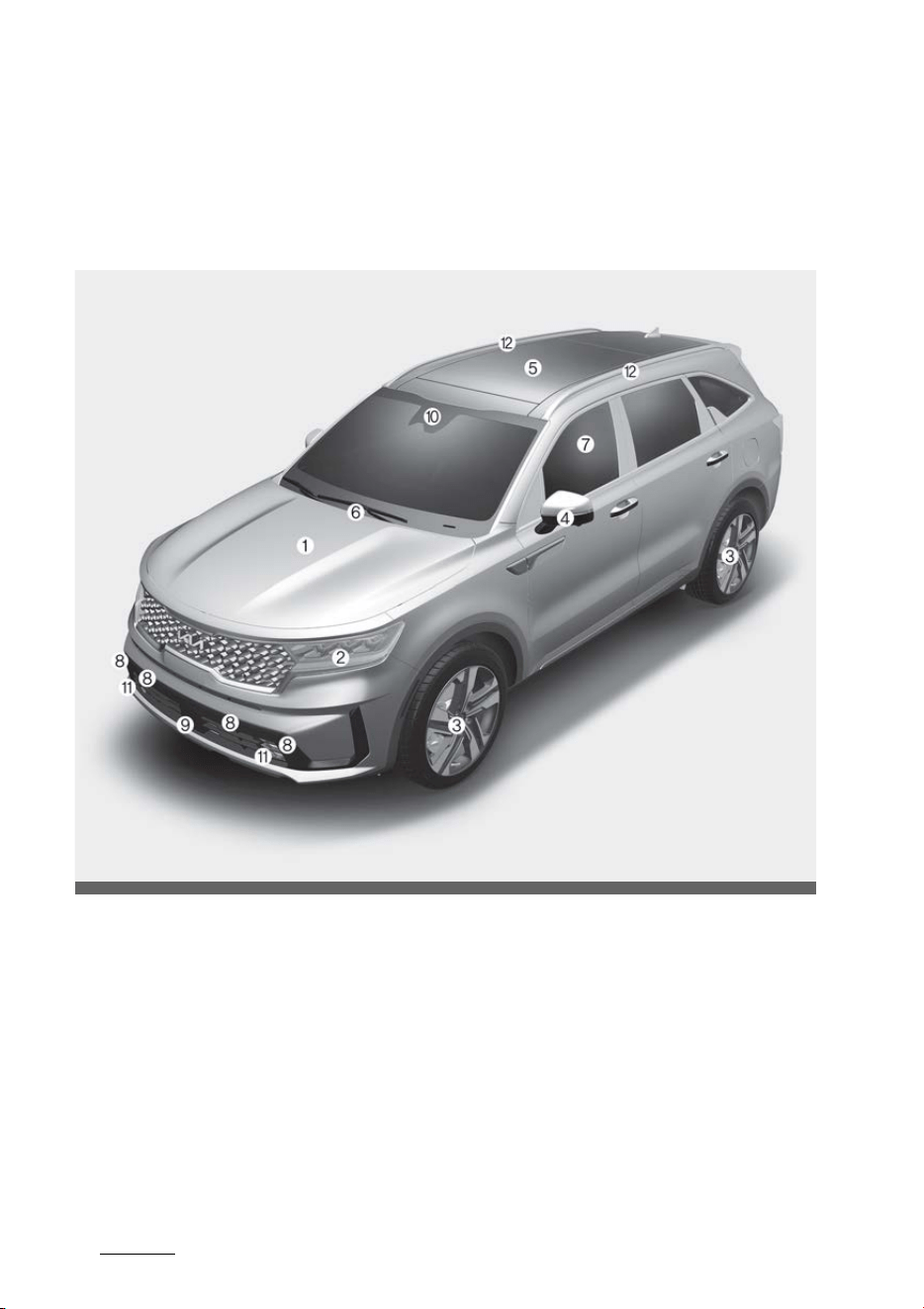
Your vehicle at a glance
23
Exterior overview
Your vehicle at a glance
Exterior overview
Front view
* The actual shape may differ from the illustration.
1. Hood 5-47
2. Headlamp 5-140, 8-68
3. Wheel and tire 7-17, 9-6
4. Outside rear view mirror 5-76
5. Panorama sunroof 5-55
6. Front windshield wiper blades 5-147, 8-32
7. Windows 5-42
8. Front ultrasonic sensors 5-134
9. Front radar 6-73
10.Front view camera 6-60, 6-73
OMQ4AH011001

3
3
3
Your vehicle at a glance Exterior overview
11.Front fog lamp 8-70
12.Roof rack 5-196
13.Charging door 1-4
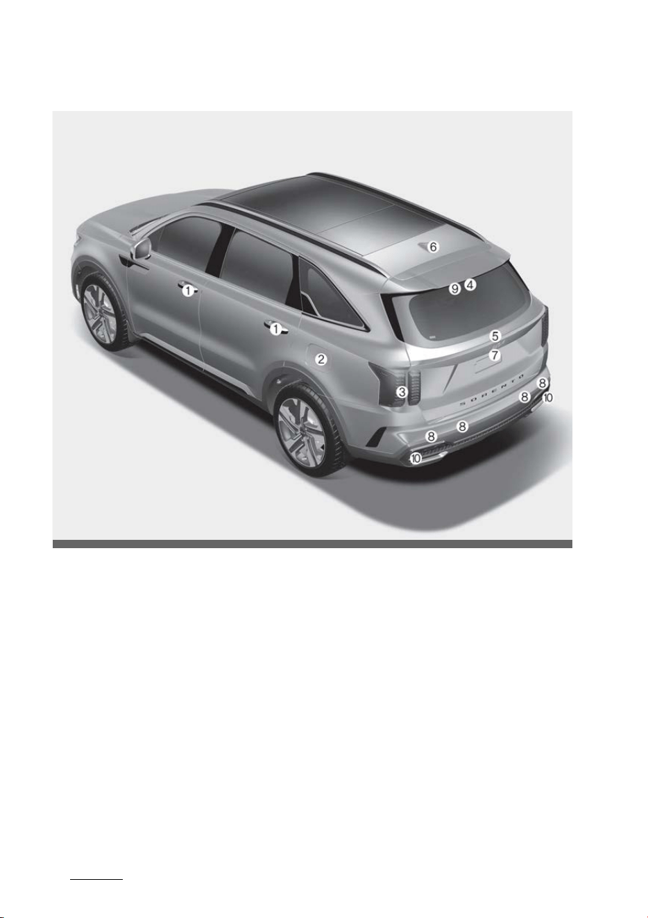
Your vehicle at a glance
43
Exterior overview
Rear view
* The actual shape may differ from the illustration.
1. Doors 5-17
2. Fuel filler door 5-48
3. Rear combination lamp 8-71, 8-72, 8-73
4. High mounted stop lamp 8-74
5. Liftgate 5-29, 5-32, 5-38
6. Antenna 5-197
7. Rear view camera 5-124
8. Rear ultrasonic sensors 5-130, 5-134
9. Rear wiper 5-147, 8-32
10.Reversing lamp 8-73
OMQ4AH011002
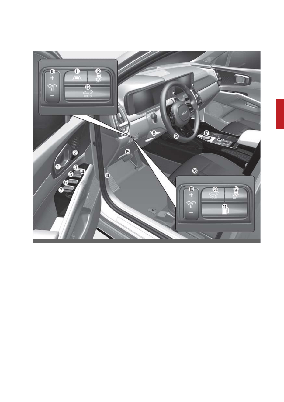
5
3
3
Your vehicle at a glance Interior overview
Interior overview
* The actual shape may differ from the illustration.
1. Inside door handle 5-19
2. Seat position memory system 5-26
3. Outside rear view mirror folding switch 5-76
4. Outside rear view mirror control switch 5-76
5. Central door lock/unlock switch 5-19
6. Power window switches 5-43
7. Power window lock button 5-45
Electronic power child safety lock button 5-22
8. Steering wheel tilt/telescopic lever 5-61
9. Steering wheel 5-60
10.Instrument panel illumination control switch 5-82
11.Fuel door open button 5-49
12.ESC OFF button 6-44
OMQ4011006N

Your vehicle at a glance
63
Interior overview
13.Power liftgate open/close button 5-29, 5-32, 5-38
14.Hood release lever 5-47
15.Instrument panel fuse 8-51
16.Seat 4-5
17.Shift dial SBW 6-14
18.Lane Safety button 6-89
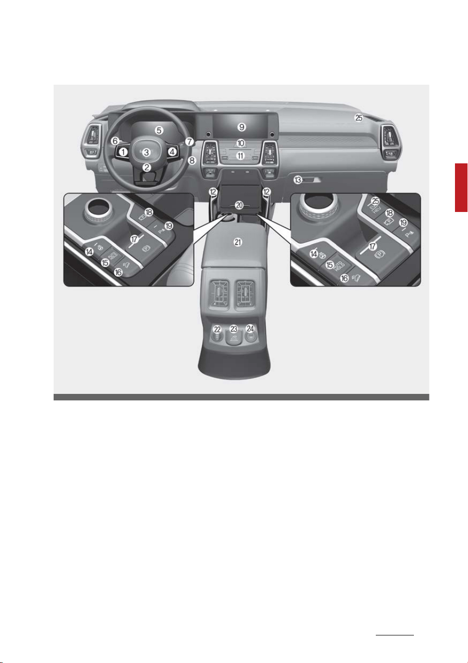
7
3
3
Your vehicle at a glance Instrument panel overview
Instrument panel overview
* The actual shape may differ from the illustration.
1. Audio remote control button 5-60
2. Driver's front air bag 4-60
3. Horn 5-63
4. Driving Assist button 6-136, 6-139
5. Instrument cluster 5-80
6. Light control/turn signals lever 5-140
7. Wiper and washer control lever 5-147
8. ENGINE START/STOP button 6-9
9. Infotainment system 5-197
10.Hazard warning flasher switch 7-2
11.Climate control system 5-161
12.Front seat warmer and air ventilation seat button 5-179, 5-181
13.Glove box 5-176
OMQ4PH011004N

Your vehicle at a glance
83
Instrument panel overview
14.Steering wheel heater button 5-62
15.AUTO HOLD button 6-39
16.DBC switch 6-47
17.EPB switch 6-34
18.Parking/View button 5-124, 5-126
19.Parking Safety button 5-130, 5-134
20.Wireless charging system 5-187
21.Center console storage box 5-176
22.Power outlet 5-184
23.AC Inverter 5-183
24.USB charger 5-183
25.Passenger's front air bag 4-60
26.EV/HEV button 1-22
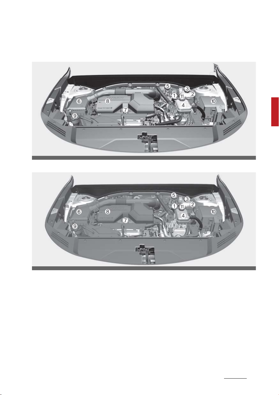
9
3
3
Your vehicle at a glance Engine compartment
Engine compartment
Smartstream G1.6 T-GDi HEV
Smartstream G1.6 T-GDi PHEV
* The actual engine room in the vehicle may differ from the illustration.
1. Electric Control Unit (ECU) 8-5
2. Engine coolant reservoir 8-22
3. Engine coolant reservoir cap 8-22
4. Inverter coolant reservoir 8-24
5. Brake fluid reservoir 8-26
6. Air cleaner 8-30
7. Engine oil dipstick 8-20
8. Engine oil filler cap 8-20
9. Windshield washer fluid reservoir 8-28
10.Fuse box 8-51
OMQ4H070021
OMQ4PH070021L

Your vehicle at a glance
103
Engine compartment
11.Inverter coolant reservoir cap 8-22

4Safety features of your vehicle
Safety feat ures of your veh icle
Important safety precautions ................................................ 4-3
Seat ............................................................................................. 4-5
䳜 Feature of Seat Leather........................................................ 4-8
䳜 Front seat adjustment for manual seat ............................ 4-8
䳜 Front seat adjustment for power seat ............................4-10
䳜 Rear seat adjustment..........................................................4-12
䳜 Headrest (for front seat)....................................................4-18
䳜 Headrest (for rear seat)......................................................4-21
䳜 Seatback pocket ...................................................................4-23
䳜 Small pocket ..........................................................................4-24
Seat belts .................................................................................4-24
䳜 Seat belt restraint system .................................................4-24
䳜 Seat belt precautions........................................................... 4-33
䳜 Care of seat belts .................................................................4-35
Child Restraint System (CRS) ...............................................4-36
䳜 Children always in the rear.................................................4-36
䳜 Selecting a CRS .....................................................................4-37
䳜 Installing a CRS......................................................................4-39
Air bag - Advanced Supplemental Restraint System.......4-46
䳜 How does the air bag system operate .............................4-47
䳜 Air bag warning and indicator ............................................4-49
䳜 Supplemental Restraint System (SRS) components and
functions ................................................................................4-50
䳜 Occupant Detection System (ODS).................................... 4-53
䳜 Driver's and passenger's front air bag..............................4-60
䳜 Side air bag ............................................................................ 4-63
䳜 Curtain air bag ......................................................................4-64
䳜 Air bag collision sensors ......................................................4-66

4 Safety features of your vehicle
䳜 Why didn't my air bag go off in a collision?
(Inflation and non-inflation conditions of the air bag)...4-67
䳜 Supplemental Restraint System (SRS) care ....................4-70
䳜 Additional safety precautions ............................................4-71
䳜 Adding equipment to or modifying
your air bag-equipped vehicle ............................................4-72
䳜 Air bag warning labels .........................................................4-73

3
4
4
Safety features of your vehicle Important safety precautions
Safety features of your vehicle
For the safety of the driver and
vehicle passengers, you should
become familiar with the vehicle's
safety features.
Important safety precautions
You will find many safety precau
-
tions and recommendations
throughout this section, and
throughout this manual.
The safety precautions in this sec
-
tion are among the most important.
Always wear your seat belt
A seat belt is your best protection in
all types of accidents. Air bags are
designed to supplement seat belts,
not replace them. So even though
your vehicle is equipped with air
bags, ALWAYS make sure you and
your passengers always wear their
seat belts, and wear them properly.
Restrain all children
All children under age 13 should ride
in your vehicle properly restrained in
a rear seat, not the front seat.
Infants and small children should be
restrained in an appropriate child
restraint. Larger children should use
a booster seat with the lap/shoulder
belt until they can use the seat belt
properly without a booster seat.
Air bag hazards
While air bags can save lives, they
can also cause serious or fatal inju
-
ries to occupants who sit too close
to them, or who are not properly
restrained. Infants, young children,
and shorter adults are at the great
-
est risk of being injured by an inflat
-
ing air bag. Follow all instructions
and warnings in this manual.
Driver distraction
Driver distraction presents a serious
and potentially deadly danger, espe
-
cially for inexperienced drivers.
Safety should be the first concern
when behind the wheel and drivers
need to be aware of the wide array
of potential distractions, such as
drowsiness, reaching for objects,
eating, personal grooming, other
passengers, and using cellular
phones.
Drivers can become distracted when
they take their eyes and attention
off the road or their hands off the
wheel to focus on activities other
than driving. To reduce your risk of
distraction or getting into an acci
-
dent:

Safety features of your vehicle
44
Important safety precautions
䳜 ALWAYS set up your mobile
devices (i.e., MP3 players, phones,
navigation units, etc.) when your
vehicle is parked or safely
stopped.
䳜 ONLY use your mobile device
when allowed by laws and when
conditions permit safe use.
NEVER text or email while driving.
Most states have laws prohibiting
drivers from texting. Some states
and cities also prohibit drivers
from using handheld phones.
䳜 NEVER let the use of a mobile
device distract you from driving.
You have a responsibility to your
passengers and others on the
road to always drive safely, with
your hands on the wheel as well
as your eyes and attention on the
road.
Control your speed
Excessive speed is a major factor in
crash injuries and deaths. Generally,
the higher the speed, the greater
the risk, but serious injuries can also
occur at lower speeds. Never drive
faster than is safe for current driv
-
ing conditions, regardless of the
maximum speed posted.
Keep your vehicle in safe condition
Having a tire blowout or a mechani
-
cal failure can be extremely hazard
-
ous. To reduce the possibility of
such problems, check your tire pres
-
sures and conditions frequently, and
perform all regularly scheduled
maintenance.
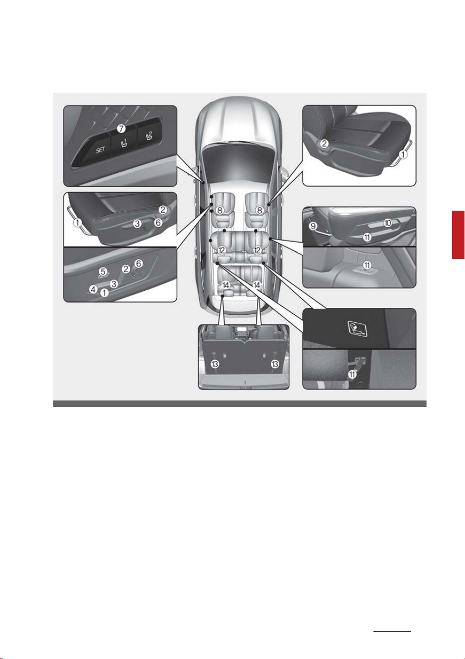
5
4
4
Safety features of your vehicle Seat
Seat
* The actual feature in the vehicle may differ from the illustration.
Front seat
1. Forward and backward
2. Seatback angle
3. Seat cushion height
4. Seat cushion tilt
5. Cushion extension (Driver's seat)
6. Lumbar support
7. Driver position memory system
8. Headrest
2nd row seat
9. Forward and backward
10.Seatback angle and folding
11.Walk-in switch/strap
12.Headrest
3rd row seat
13.Folding
14.Headrest
OMQ4AH031001
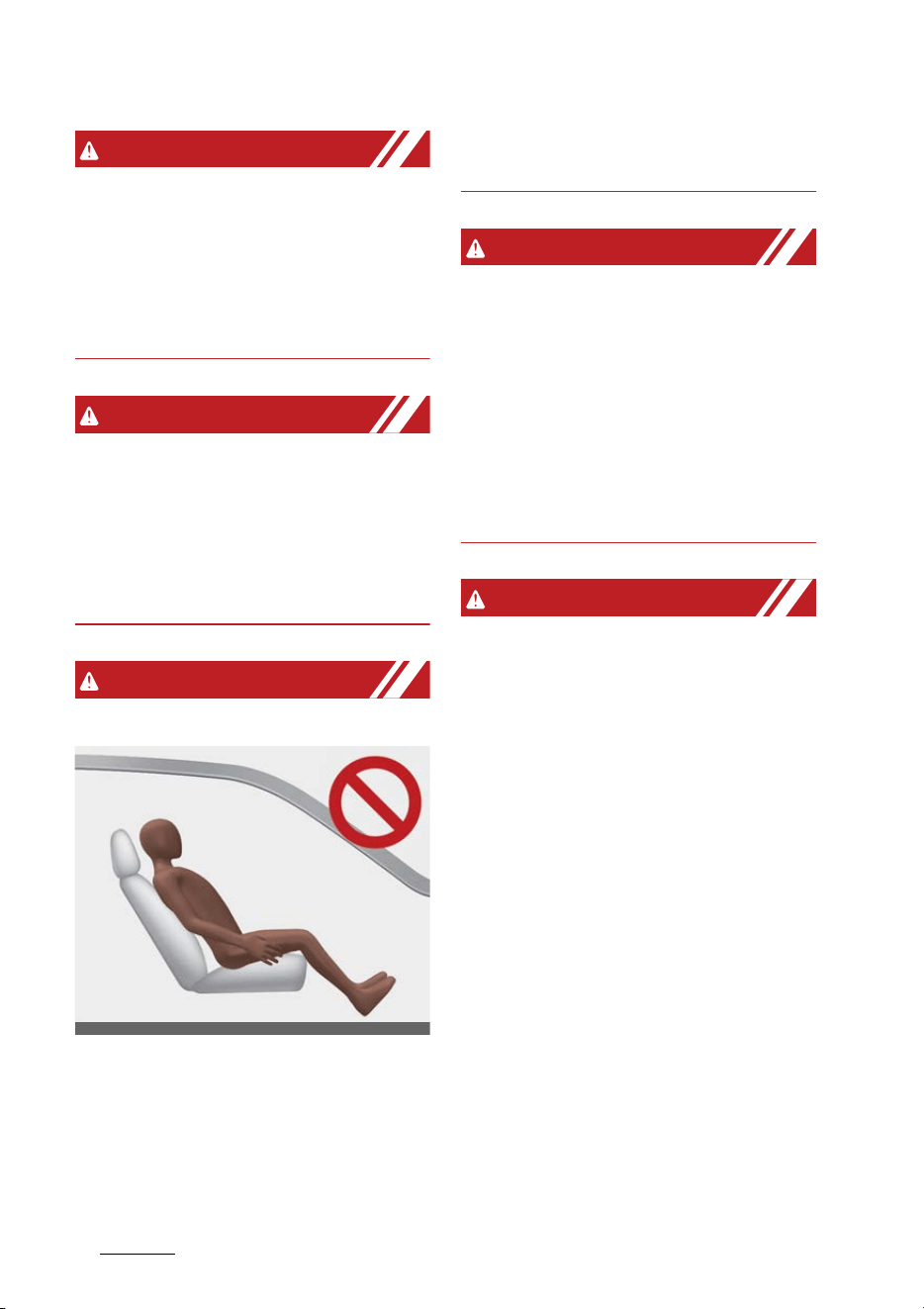
Safety features of your vehicle
64
Seat
WARNING
Loose objects
Loose objects in the driver's foot
area could interfere with the opera
-
tion of the foot pedals, possibly
causing an accident. Do not place
anything under the front seats.
WARNING
Uprighting seat
Do not press the release lever on a
manual seatback without holding
and controlling the seatback. The
seatback will spring upright, possibly
impacting you or other passengers.
WARNING
Driver responsibility for passengers
The driver must advise the passen
-
gers to keep the seatback in an
upright position whenever the vehi
-
cle is in motion. If a seat is reclined
during an accident, the restraint
system's ability to restrain the pas
-
senger will be greatly reduced.
WARNING
Seat cushion
Occupants should never sit on after
-
market seat cushions or sitting
cushions. The passenger Occupant
Detection System may not operate
properly, or the passenger's hips
may slide under the lap portion of
the seat belt during an accident or a
sudden stop.
WARNING
Driver's seat
䳜 Never attempt to adjust the seat
while the vehicle is moving. This
could result in loss of control of
your vehicle.
䳜 Do not allow anything to interfere
with the normal position of the
seatback. For example, storing
items against the seatback could
result in serious or fatal injury in a
sudden stop or collision.
䳜 Sit as far back as possible from
the steering wheel while still
maintaining comfortable control
of the your vehicle. A distance of
at least 10 inches (25 cm) from
your chest to the steering wheel
is recommended. Failure to do so
ODEEV058002NR

7
4
4
Safety features of your vehicle Seat
can result in air bag inflation inju
-
ries to the driver.
WARNING
Rear seatbacks
Always lock the rear seatback
before driving. Failure to do so could
result in passengers or objects being
thrown forward, injuring vehicle
occupants.
WARNING
Unexpected seat movement
After adjusting a manual seat,
always check that it is locked by
shifting your weight to the front
and to the back. Sudden or unex
-
pected movement of the driver's
seat could cause you to lose control
of the vehicle.
WARNING
Seat adjustment
䳜 Do not adjust the seat while
wearing seat belts. Moving the
seat forward will cause strong
pressure on the abdomen.
䳜 Do not place your hand near the
seat bottom or seat track while
adjusting the seat. Your hand
could get caught in the seat
mechanism.
WARNING
Luggage and cargo
Do not stack or pile luggage or cargo
higher than the seatback in the
cargo area. In an accident the cargo
could strike and injure a passenger.
If objects are large, heavy or must
be piled, they must be secured in
the cargo area.
WARNING
Cargo area
Do not allow passengers to ride in
the cargo area under any circum
-
stance. The cargo area is solely for
the purpose of transporting luggage
or cargo.
WARNING
Small objects
Use extreme caution when picking
up small objects trapped under the
seats or between the seat and the
center console. Your hands might be
cut or injured by the sharp edges of
the seats mechanism.
CAUTION
Precautions with seat covers
Use caution when working on the
seat cover. A short circuit or discon
-
nection may occur, which could lead

Safety features of your vehicle
84
Seat
to noise, damage the ventilation
system.
WARNING
Seat short circuit risk
Be aware of wires or air vents when
placing a seat cover or covering the
seat with plastic cover. A short cir
-
cuit may occur, which could lead to
fire.
Feature of Seat Leather (if
equipped)
䳜 Leather is made from the outer
skin of an animal, which goes
through a special process to be
available for use. Since it is a nat
-
ural substance, each part differs
in thickness or density. Wrinkles
may appear as a natural result of
stretching and shrinking depend
-
ing on the temperature and
humidity.
䳜 The seat cover is made of
stretchable material to improve
comfort of passengers.
䳜 The parts contacting the body are
curved and the side supporting
area is high which provides driving
comfort and stability.
䳜 Wrinkles may appear naturally
from usage. It is not a fault of the
product.
CAUTION
䳜 Belts with metallic accessories,
zippers or keys inside the back
pocket may damage the seat fab
-
ric.
䳜 Make sure not to wet the seat. It
may change the nature of leather.
䳜 Jeans or clothes which could
bleach may contaminate the sur
-
face of the seat covering fabric.
NOTICE
Wrinkles or abrasions may appear
naturally from usage. It is not a
fault of product. Wrinkles or abra
-
sions are not covered by warranty.
Front seat adjustment for manual
seat (if equipped)
The front seat can be adjusted by
using the control levers located on
the outside of the seat cushion.
Moving forward and backward
Adjust the seat before driving, and
make sure the seat is locked
securely by trying to move forward
and backward without using the
lever. If the seat moves, it is not
locked properly.
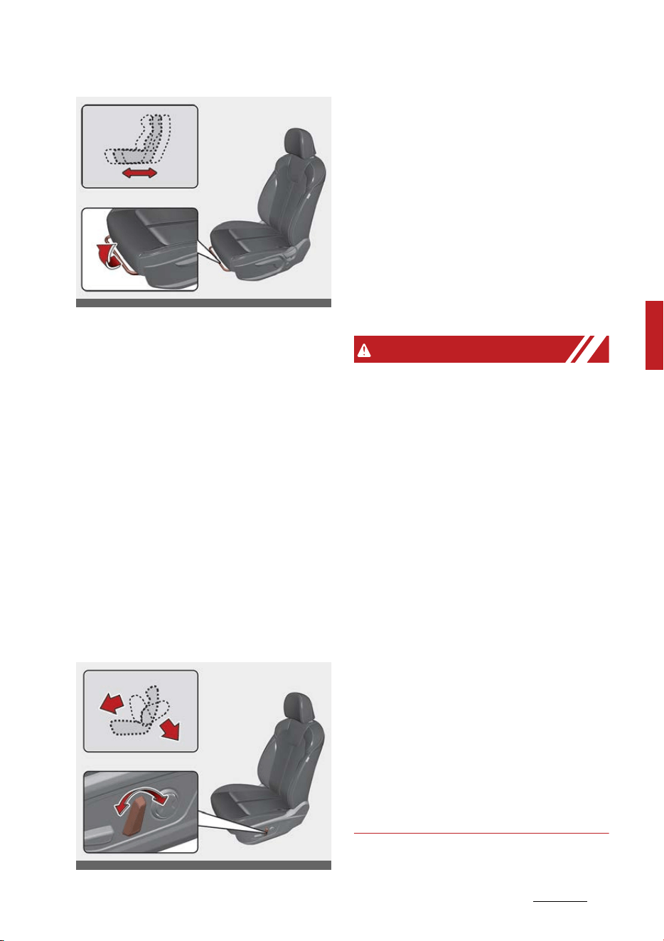
9
4
4
Safety features of your vehicle Seat
To move the seat forward or back
-
ward:
1. Pull the seat slide adjustment
lever up and hold it.
2. Slide the seat to the position you
desire.
3. Release the lever and make sure
the seat is locked in place.
Adjust the seat before driving, and
make sure the seat is locked
securely by trying to move forward
and backward without using the
lever. If the seat moves, it is not
locked properly.
Reclining seatback
To recline the seatback:
1. Lean forward slightly and lift up
the seatback recline lever.
2. Carefully lean back on the seat
and adjust the seatback of the
seat to the position you desire.
3. Release the lever and make sure
the seatback is locked in place.
(The lever MUST return to its
original position for the seatback
to lock.)
WARNING
Reclining seatback
Sitting in a reclined position when
the vehicle is in motion can be dan
-
gerous. Even when buckled up, the
protections of your restraint sys
-
tem (seat belts and/or air bags) is
greatly reduced by reclining your
seatback.
Seat belts must be snug against
your hips and chest to work prop
-
erly. When the seatback is reclined,
the shoulder belt cannot do its job
because it will not be snug against
your chest. Instead, it will be in front
of you. During an accident, you could
be thrown into the seat belt, caus
-
ing neck or other injuries.
The more the seatback is reclined,
the greater chance the passenger's
hips will slide under the lap belt or
the passenger's neck will strike the
shoulder belt.
OMQ4AH030008
OMQ4AH030013
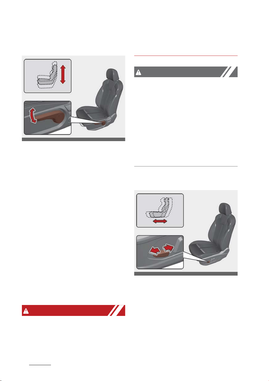
Safety features of your vehicle
104
Seat
Changing seat cushion height (for
driver's seat)
To change the height of the seat
cushion, push the lever upwards or
downwards.
䳜 To lower the seat cushion, push
down the lever several times.
䳜 To raise the seat cushion, pull up
the lever several times.
Front seat adjustment for power
seat (if equipped)
The driver's seat can be adjusted by
using the control switches located
on the outside of the seat cushion.
Before driving, adjust the seat to
the proper position so as to easily
control the steering wheel, pedals
and switches on the instrument
panel.
WARNING
Unattended children
Never leave children unattended in a
vehicle. Children might operate fea
-
tures of the vehicle that could injure
them.
CAUTION
Power seating adjustments
䳜 The power seating controls func
-
tion by electronic motor. Exces
-
sive operation may cause damage
to the electrical equipment.
䳜 Do not operate two or more
power seat control switches at
the same time. Doing so may
damage the power seat motor or
electrical components.
Moving forward and backward
To move the seat forward or back
-
ward:
1. Push the control switch forward
or backward to move the seat to
the desired position.
2. Release the switch once the seat
reaches the desired position.
OMQ4AH030010
OMQ4AH030012
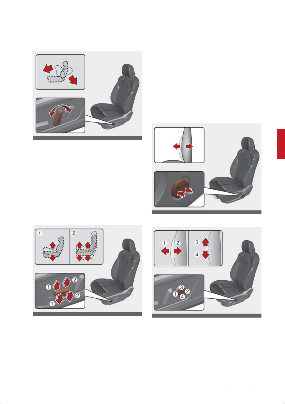
11
4
4
Safety features of your vehicle Seat
Reclining seatback
To recline the seatback:
1. Push the control switch forward
or backward to move the seat
-
back to the desired angle.
2. Release the switch once the seat
reaches the desired position.
Changing seat cushion tilt and
height
To change the height of the seat:
1. Pull the front portion of the con
-
trol switch up to raise or press
down to lower the front part of
the seat cushion.
Pull the rear portion of the control
switch up to raise or press down
to lower the seat cushion.
2. Release the switch once the seat
reaches the desired position.
Adjusting lumbar support (if
equipped)
Type A
Type B
The lumbar support can be adjusted
by pressing the lumbar support
switch on the side of the seat.
1. Press the front portion of the
switch to increase support, or the
OMQ4AH030013
OMQ4AH030015
OMQ4AH030011
OMQ4AH030016
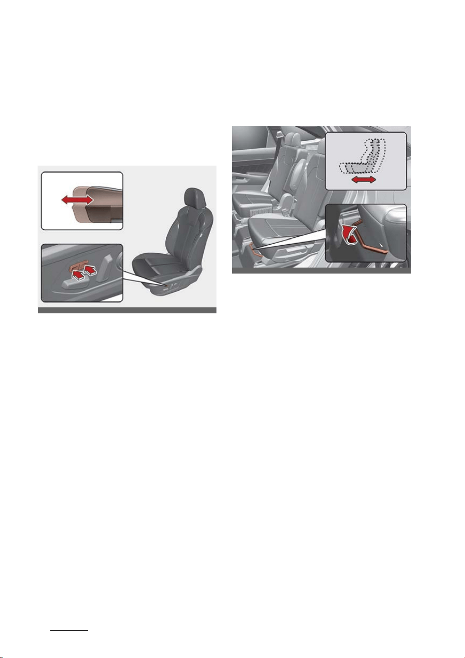
Safety features of your vehicle
124
Seat
rear portion of the switch, to
decrease support.
2. Release the switch once it
reaches the desired position.
Adjusting cushion extension for
driver's seat (if equipped)
1. Press the front portion of the
switch to raise the cushion exten
-
sion, or the rear portion of the
switch to lower it.
2. Release the switch once the cush
-
ion extension reaches the desired
position.
Rear seat adjustment
Forward and backward (2nd row
seat)
To move the seat forward or back
-
ward:
1. Pull the seat slide adjustment
lever up and hold it.
2. Slide the seat to the position you
desire.
3. Release the lever and make sure
the seat is locked in place.
Adjust the seat before driving, and
make sure the seat is locked
securely by trying to move forward
and backward without using the
lever. If the seat moves, it is not
locked properly.
OMQ4AH030014
OMQ4AH030026

13
4
4
Safety features of your vehicle Seat
Seatback angle (2nd row seat)
To recline the seatback:
1. Pull up the seatback recline lever.
2. Hold the lever and adjust the
seatback of the seat to the posi
-
tion you desire.
3. Release the lever and make sure
the seatback is locked in place.
(The lever MUST return to its
original position for the seatback
to lock.)
Walk-in seat (2nd row seat)
To get in or out of the 3rd row seat:
1. Routing the seat belt webbing
through the rear seat belt guide
clip. After inserting the seat belt,
tighten the belt webbing by pull
-
ing it up.
2. Press the switch (1) on the top of
the 2nd row seat or press the
switch (2) on the bottom of the
2nd row seat to unlock.
Or, the 2nd row seat can be
unlocked by pulling the strap
located beneath the 2nd row seat
seatback. If the strap is located
beneath the 2nd row seatback,
there is a label attached to show
where the strap is located in.
OMQ4AH030029
OMQ4030006
OMQ4AH030034
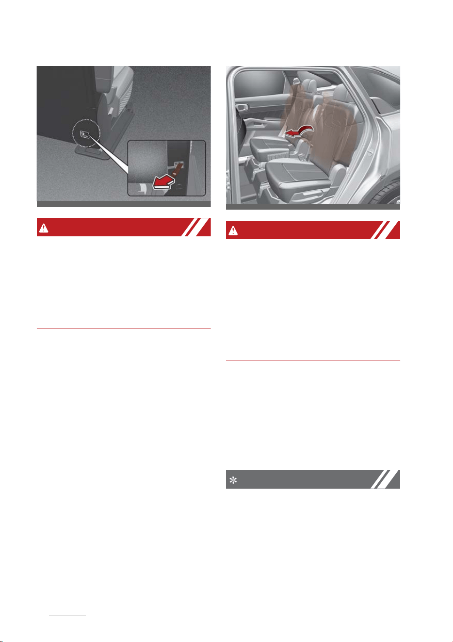
Safety features of your vehicle
144
Seat
WARNING
Never attempt to adjust using the
2nd row seat walk-in switch or
strap while the vehicle is moving or
seat is occupied as the seat may
suddenly move and cause the pas
-
senger on the seat to be injured.
3. The 2nd row seatback will be
folded and push the seat to the
farthest forward position.
After getting in or out, slide the
2nd row seat to the farthest
backward position and pull the
seatback firmly backward until it
clicks into place. Make sure that
the seat is locked in place.
WARNING
Do not pull the strap when the 2nd-
row seats are occupied.
Sudden movement of the seats may
result in injury. Use the strap only
when the folding switch in the 2nd
row (in the upper part of the sec
-
ond-row seatback or the outer part
of the seat) does not work.
Folding the rear seat
The rear seatbacks can be folded to
facilitate carrying long items or to
increase the luggage capacity of the
vehicle.
NOTICE
Folded seatback
Do not sit on folded down seat
-
backs. The purpose of the fold-
down rear seatbacks is to allow you
to carry longer objects that could
not otherwise be accommodated.
OMQ4030090
OMQ4AH030035
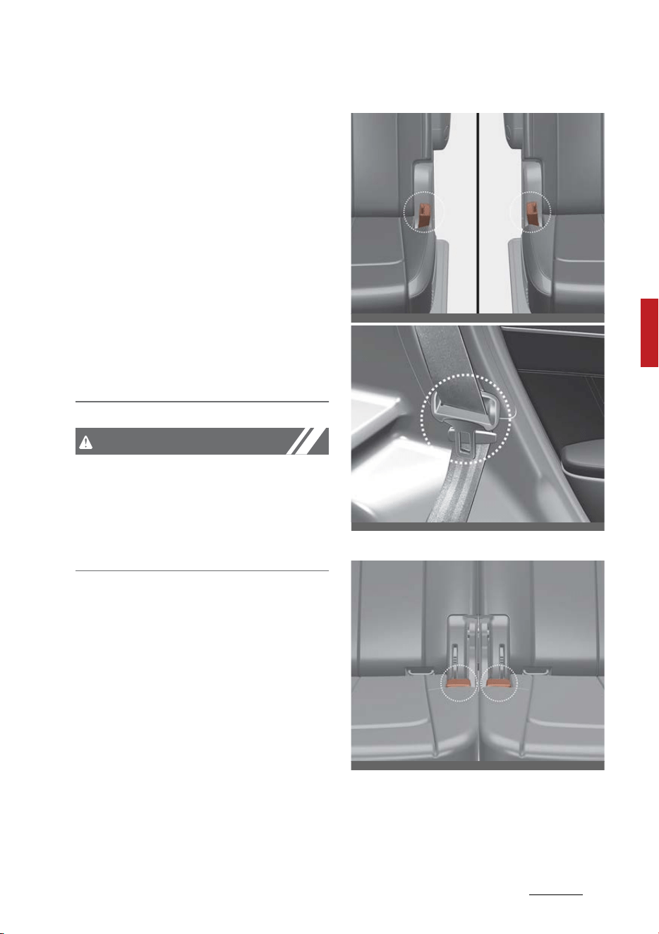
15
4
4
Safety features of your vehicle Seat
䳜 Never allow a passenger to sit on
top of the folded down seatback
while the car is moving. This is not
a proper seating position since
the seat has important crash pro
-
tection features and seat belts
are not available in this seat con
-
figuration.
䳜 To reduce the risk of injury caused
by sliding cargo within the pas
-
senger compartment of the vehi
-
cle, objects carried on the folded
down seatback should not extend
higher than the top of the front
seats.
CAUTION
Blocked Hybrid battery duct
Do not put objects on the left side of
rear seats. This could block the bat
-
tery cooling duct causing battery
degradation.
1. Insert the rear seat belt buckle in
the pocket between the rear
seatback and cushion, and insert
the rear seat belt webbing in the
guide to prevent the seat belt
from being damaged.
2nd row seat
3rd row seat
OMQ4AH030071
OMQ4030006
OMQ4AH030072
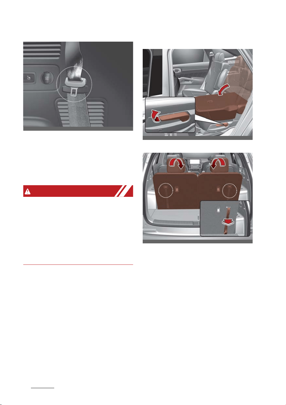
Safety features of your vehicle
164
Seat
2. Set the front seatback to the
upright position and if necessary,
slide the front seat forward.
3. Lower the rear headrests to the
lowest position.
WARNING
Objects
Objects carried on the folded down
seatback should not extend higher
than the top of the front seatbacks.
This could allow cargo to slide for
-
ward and cause injury or damage
during sudden stops.
4. Pull on the seatback folding lever
(for 2nd row) or strap (for 3rd
row), then fold the seat toward
the front of the vehicle. When you
return the seatback to its upright
position, always be sure it has
locked into position by pushing on
the top of the seatback.
2nd row seat
3rd row seat
5. To use the rear seat, lift and pull
the seatback backward by pulling
on the folding lever (for 2nd row)
or strap (for 3rd row). Pull the
seatback firmly until it clicks into
place. Make sure the seatback is
locked in place.
OMQ4030003
OMQ4AH030036
OMQ4AH030037
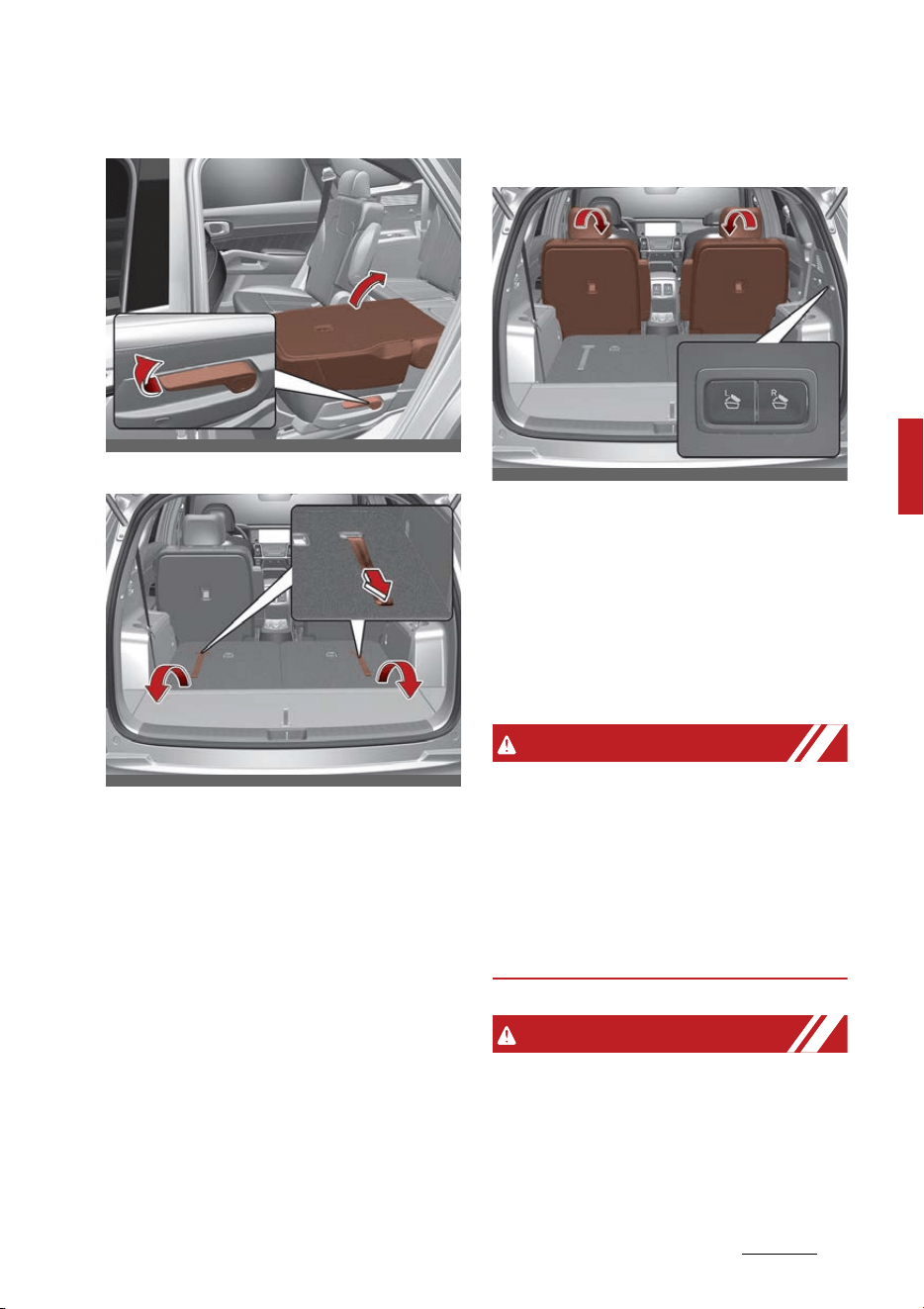
17
4
4
Safety features of your vehicle Seat
2nd row seat
3rd row seat
6. Return the rear seat belt to the
proper position.
2nd row seat folding (from 3rd
row)
2nd row seat folding switch is
located on the right side of the 3rd
row seat. The 2nd row seat back will
be folded. If you press the left
switch, left side seat back and cen
-
ter seat back will be folded. If you
press the right switch, right side
seat back will be folded.
WARNING
Do not fold the rear seatbacks down
until the driver has positioned his
seat properly. Doing so can cause
the driver to operate the vehicle out
of position and increase the risk of
bodily injury in a sudden stop or col
-
lision.
WARNING
Uprighting seat
When you return the seatback to its
upright position, hold the seatback
and return it slowly. If the seatback
is returned without holding it, the
OMQ4AH030038
OMQ4AH030039
OMQ4AH030040

Safety features of your vehicle
184
Seat
back of the seat could spring for
-
ward, resulting in injury caused by
being struck by the seatback.
WARNING
Rear seatback
To ensure maximum protection in
the event of an accident or sudden
stop, when returning the rear seat
to the upright position:
䳜 Be careful not to damage the seat
belt webbing or buckle.
䳜 Do not allow the seat belt web
-
bing or buckle to become pinched
or caught in the rear seat.
䳜 Ensure the seatback is completely
locked into its upright position by
pushing on the top of the seat
-
back.
CAUTION
Damaging rear seat belt buckles
When you fold the rear seatback,
insert the buckle between the rear
seatback and cushion. Doing so can
prevent the buckle from being dam
-
aged by the rear seatback.
CAUTION
Rear seat belts
When returning the rear seatbacks
to the upright position, remember
to return the rear shoulder belts to
their proper position.
WARNING
Cargo
Cargo should always be secured to
prevent it from being thrown about
the vehicle in a collision and causing
injury to the vehicle occupants. Do
not place objects in the rear seats,
since they cannot be properly
secured and may hit the front seat
occupants in a collision.
WARNING
Cargo loading
Make sure the engine is off, the
shift dial SBW is in P (Park) and the
parking brake is securely applied
whenever loading or unloading
cargo. Failure to take these steps
may allow the vehicle to move if the
shift lever is inadvertently moved to
another position.
Headrest (for front seat)
The driver's and front passenger's
seats are equipped with a headrest
for the occupant's safety and com
-
fort.
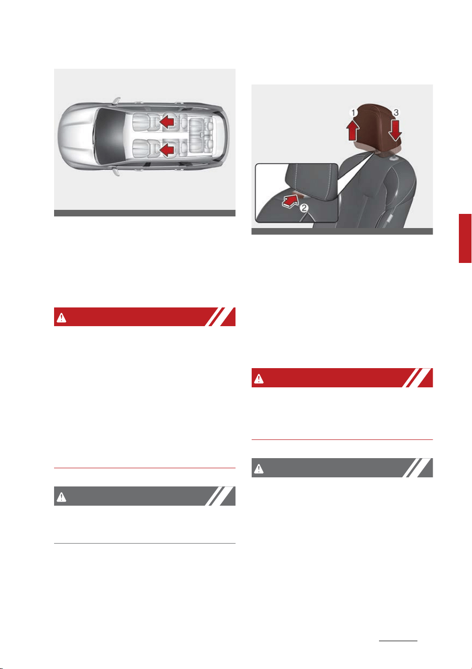
19
4
4
Safety features of your vehicle Seat
The headrest not only provides
comfort for the driver and front
passenger, but also helps protect
the head and neck in the event of a
collision.
WARNING
Headrest removal/adjustment
䳜 Do not operate the vehicle with
the headrests removed. Head
-
rests can provide critical neck and
head support in a crash.
䳜 Do not adjust the headrest height
while the vehicle is in motion.
Driver may lose control of the
vehicle.
CAUTION
Excessive pulling or pushing may
damage the headrest.
Adjusting the height up and down
To raise the headrest:
1. Pull it up to the desired position
(1).
2. To lower the headrest, push and
hold the release button (2) on the
headrest support.
3. Lower the headrest to the desired
position (3).
WARNING
Make sure the headrest locks in
position after adjusting it to prop
-
erly protect the occupants.
CAUTION
If you recline the seatback towards
the front with the headrest and
seat cushion raised, the headrest
may come in contact with the sun
visor or other parts of the vehicle.
OMQ4AH030108
OMQ4AH030020
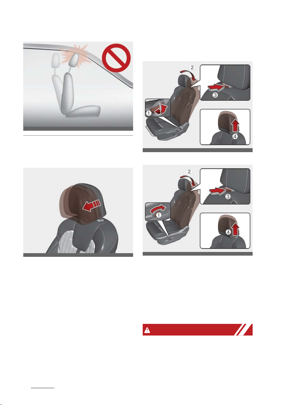
Safety features of your vehicle
204
Seat
Forward and backward adjustment
(if equipped)
The headrest may be adjusted for
-
ward to 3 different positions by
pulling the headrest forward to the
desired position.
To adjust the headrest to it's fur
-
thest backwards position, pull it fully
forward to the farthest position and
release it.
Adjust the headrest so that it prop
-
erly supports the head and neck.
Removing headrest
Type A
Type B
To remove the headrest:
1. Recline the seatback (2) with the
recline lever or switch (1).
2. Raise headrest as far as it can go.
3. Press the headrest release button
(3) while pulling the headrest up
(4).
WARNING
Removing headrest
NEVER allow anyone to ride in a
seat with the headrest removed or
reversed. Headrests can provide
ODEEV058008NR
OMQ4030021
OMQ4AH030022
OMQ4AH030024
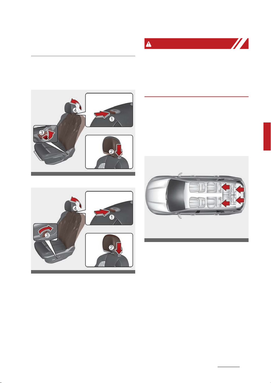
21
4
4
Safety features of your vehicle Seat
critical neck and head support in a
crash.
Reinstalling headrest
Type A
Type B
To reinstall the headrest:
1. Recline the seatback (4) with the
recline lever or switch (3).
2. Put the headrest poles (2) into
the holes while pressing the
release button (1).
3. Adjust the headrest to the appro
-
priate height.
WARNING
Headrest reinstallation
To reduce the risk of injury to the
head or neck, always make sure the
headrest is locked into position and
adjusted properly after reinstalling.
Headrest (for rear seat)
The rear seats are equipped with
headrests in all the seating positions
for the occupant's safety and com
-
fort.
The headrest not only provides
comfort for passengers, but also
helps protect the head and neck in
the event of a collision.
For maximum effectiveness in case
of accidents, the headrest should be
adjusted so the middle of the head
-
rest is as high as the center of grav
-
ity of an occupant's head. Generally,
the center of gravity of most peo
-
ple's heads is similar with the height
as the top of their eyes.
OMQ4AH030023
OMQ4AH030025
OMQ4AH030083
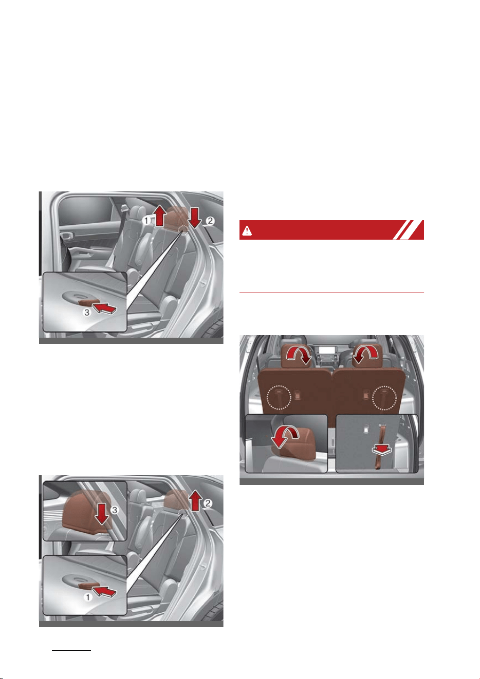
Safety features of your vehicle
224
Seat
Also, adjust the headrest as close to
your head as possible. For this rea
-
son, the use of a cushion that holds
the body away from the seatback is
not recommended.
Adjusting the height up and down
(2nd row seat)
To raise the headrest, pull it up to
the desired position (1). To lower
the headrest, push and hold the
release button (3) on the headrest
support and lower the headrest to
the desired position (2).
Removal (2nd row seat)
To remove the headrest, raise it as
far as it can go then press the
release button (1) while pulling the
headrest up (2).
To reinstall the headrest, put the
headrest poles (3) into the holes
while pressing the release button
(1). Then adjust it to the appropri
-
ate height.
WARNING
Make sure the headrest locks in
position after adjusting it to prop
-
erly protect the occupants.
3rd row headrest
OMQ4AH030031
OMQ4AH030032
OMQ4AH030106
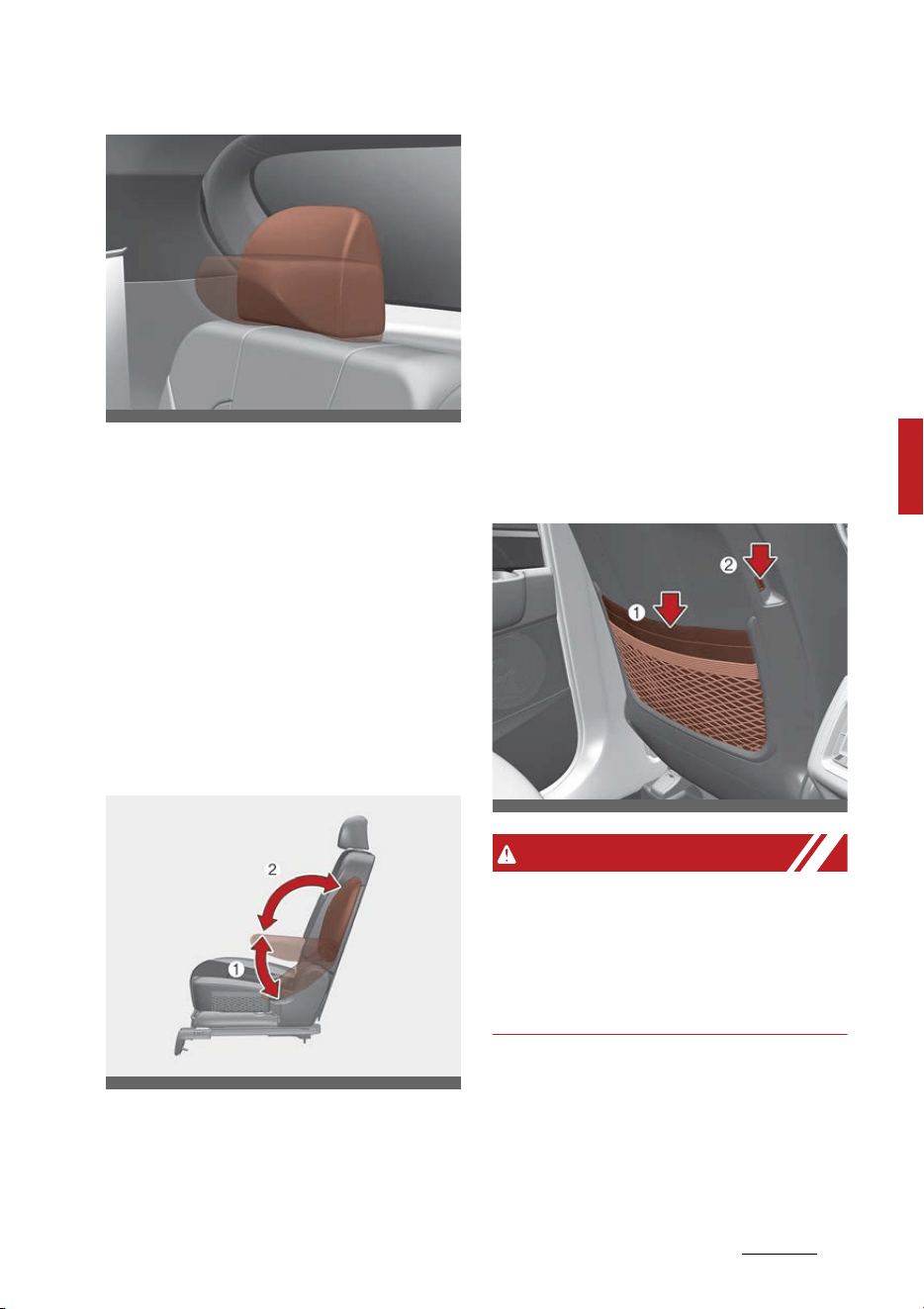
23
4
4
Safety features of your vehicle Seat
The headrest will fold down auto
-
matically when folding the seatback.
To fold the headrest manually, pull
the strap.
To unfold the headrest, raise the
headrest manually.
Always be sure the headrest has
locked into position after you return
the seatback.
Armrest
To use the armrest, pull it forward
from the seatback.
Adjustable armrest is located on
each side of 2nd row seatback. To
use the armrest, pull it forward
from the seatback and adjust to
desired angle. Pull it backward to
relocate the armrest.
Seatback pocket (if equipped)
There is a double pocket (1) in the
front seat back for storing simple
books or atlases, and USB charger
(2) (if equipped) for rear passen
-
gers.
WARNING
Seatback pockets
Do not put heavy or sharp objects in
the seatback pockets. In an accident
they could come loose from the
pocket and injure vehicle occupants.
OMQ4AH030107
OMQ4AH030088
OMQ4030027
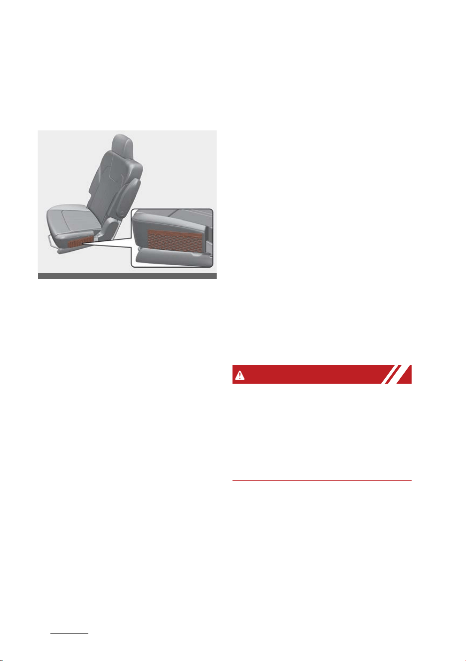
Safety features of your vehicle
244
Seat belts
Small pocket
There is a small pocket in the 2nd
row seat cushion for storing simple
objects.
Seat belts
Seat belts are designed to bear upon
the bony structure of the body, and
should be worn low across the front
of the pelvis, chest and shoulders.
Seat belt restraint system
For maximum restraint system pro
-
tection, the seat belts must always
be used whenever the vehicle is
moving.
䳜 A properly positioned shoulder
belt should be positioned midway
over your shoulder, across your
collarbone.
䳜 Never allow children to ride in the
front passenger seat. See "Child
Restraint System (CRS)" on page
4-36 for further discussion.
WARNING
Twisted seat belt
Make sure your seat belt is not
twisted when worn. A twisted seat
belt may not properly protect you in
an accident and could even cut into
your body.
OMQ4AH030089

25
4
4
Safety features of your vehicle Seat belts
WARNING
Shoulder belt
䳜 Never wear the shoulder belt
under your arm or behind your
back. An improperly positioned
shoulder belt cannot protect the
occupant in the event of a crash.
䳜 Always wear both the shoulder
portion and lap portion of the lap/
shoulder belt.
WARNING
Damaged seat belt
Any damage in webbing or hardware
may lead to serious injury or death
in a crash. For your safety, replace
the entire seat belt assembly when
any part of the webbing or hard
-
ware is damaged.
Seat belts are designed to bear upon
the bony structure of the body, and
should be worn low across the front
of the pelvis, chest and shoulders,
as applicable; wearing the lap sec
-
tion of the belt across the abdomi
-
nal area must be avoided.
Seat belts should be adjusted as
firmly as possible, consistent with
comfort, to provide the protection
for which they have been designed.
A slack belt will greatly reduce the
protection afforded to the wearer.
Care should be taken to avoid con
-
tamination of the webbing with pol
-
ishes, oils and chemicals, and
particularly battery acid. Cleaning
may safely be carried out using mild
soap and water. The belt should be
replaced if webbing becomes frayed,
contaminated or damaged.
䳜 No modifications or additions
should be made by the user which
would either prevent the seat belt
adjusting devices from operating
to remove slack, or prevent the
seat belt assembly from being
adjusted to remove slack.
䳜 When you fasten the seat belt, be
careful not to latch the seat belt
in buckles of other seats. It is very
dangerous and you may not be
protected by the seat belt prop
-
erly.
䳜 Do not unfasten the seat belt and
do not fasten and unfasten the
seat belt repeatedly while driving.
This could result in loss of control,
and an accident causing death,
serious injury, or property dam
-
age.
䳜 When fastening the seat belt,
make sure that the seat belt does
not pass over objects that are
hard or can break easily.

Safety features of your vehicle
264
Seat belts
WARNING
Seat belt buckle
Do not allow foreign material (gum,
crumbs, coins, liquids, etc.) to
obstruct the seat belt buckle. This
may prevent the seat belt from fas
-
tening securely.
Seat belt warning
The seat belt warning light and
warning chime operate under the
following conditions.
Driver's seat belt warning
As a reminder to the driver, the seat
belt warning light will illuminate for
approximately 6 seconds each time
you turn the ENGINE START/STOP
button ON regardless of belt fas
-
tening. If the seatbelt is not fas
-
tened, the warning chime will sound
for about 6 seconds.
If you start to drive without the
seat belt fastened over approxi
-
mately 5 mph (9 km/h) and less
than approximately 12 mph (20 km/
h), the corresponding warning light
will illuminate. The warning light will
turn off when the vehicle speed
drops below approximately 5 mph
(9 km/h).
If you start to drive without the
seat belt fastened or you unfasten
the seat belt when you drive
approximately 12 mph (20 km/h)
and faster, the warning light will
blink and warning chime will sound
for approximately 100 seconds.
When the seat belt is unfastened
during driving, the warning light will
illuminate when the speed is under
approximately 12 mph (20 km/h).
When the speed is approximately 12
mph (20 km/h) and faster, the
warning light will blink and warning
chime will sound for approximately
100 seconds.
Front passenger's seat belt warn
-
ing
As a reminder to the front passen
-
ger, the seat belt warning light will
illuminate for approximately 6 sec
-
onds each time you turn the ENGINE
START/STOP button ON regardless
of belt fastening. If you start to
drive without the passenger seat
belt fastened when you drive over
approximately 5 mph (9 km/h) and
less than approximately 12 mph (20
km/h), the corresponding warning
light will illuminate. The warning
light will turn off when the vehicle
speed drops approximately below 5
mph (9 km/h).
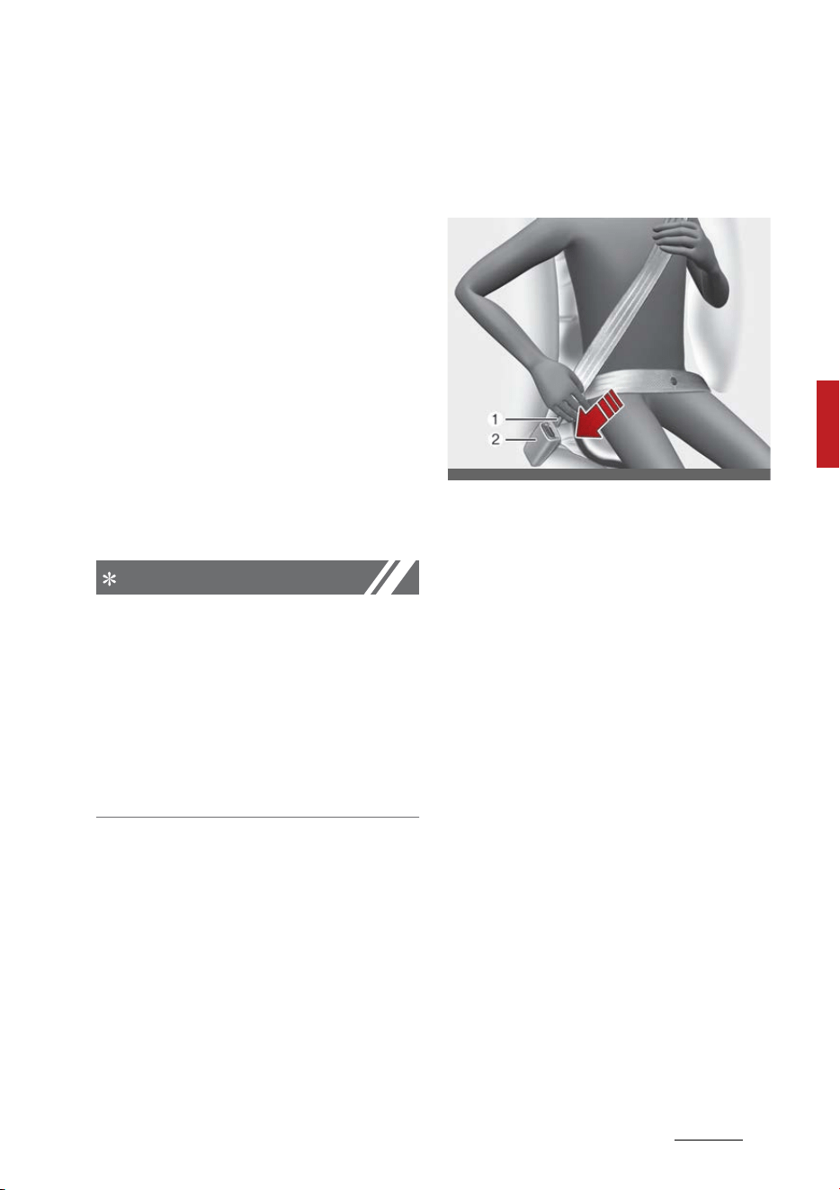
27
4
4
Safety features of your vehicle Seat belts
If you start to drive without the
passenger seat belt fastened or you
unfasten the seat belt when you
drive approximately 12 mph (20 km/
h) and faster, the warning light will
blink and warning chime will sound
for approximately 100 seconds.
When the passenger seat belt is
unfastened during driving, the
warning light will illuminate when
the speed is approximately under 12
mph (20 km/h). When the speed is
approximately 12 mph (20 km/h)
and faster, the warning light will
blink and warning chime will sound
for approximately 100 seconds.
NOTICE
䳜 Even if the front passenger seat
is not occupied, the seat belt
warning light will illuminate for
approximately 6 seconds.
䳜 The front passenger's seat belt
warning may operate when lug
-
gage is placed on the front pas
-
senger seat.
Seat belt - Driver's 3-point system
with emergency locking retractor
Fastening the seat belt
䳜 To fasten your seat belt, pull it
out of the retractor and insert the
metal tab (1) into the buckle (2).
There will be an audible "click"
when the tab locks into the
buckle.
The seat belt automatically adjusts
to the proper length only after the
lap belt portion is adjusted manually
so that it fits snugly around your
hips. If you lean forward in a slow,
easy motion, the belt will extend
and let you move around. If there is
a sudden stop or impact, however,
the belt will lock into position. It will
also lock if you try to lean forward
too quickly.
ODEEV058025NR
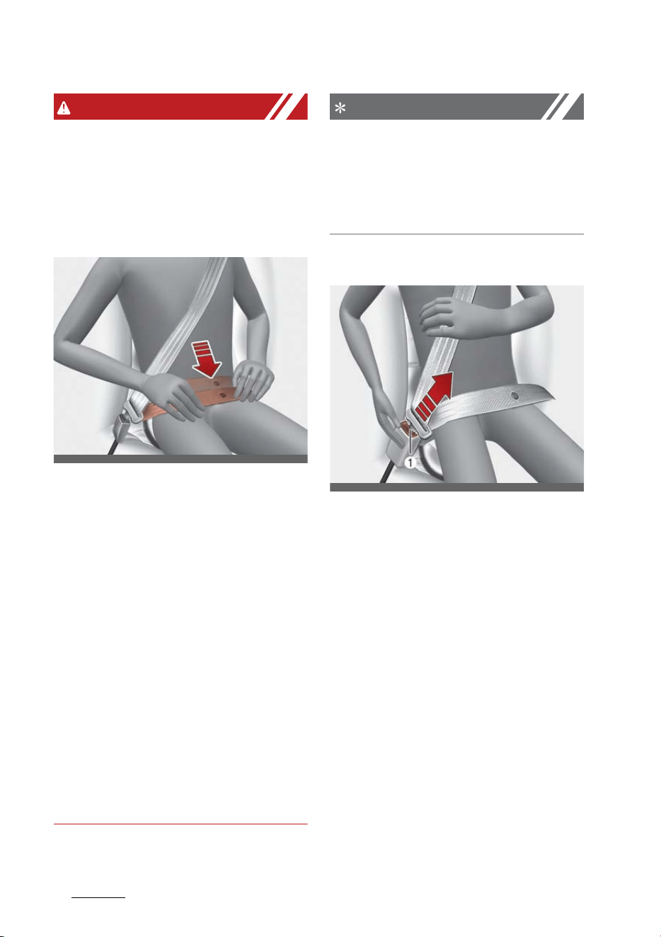
Safety features of your vehicle
284
Seat belts
WARNING
You should place the lap belt portion
as low as possible and snugly across
your hips. If the lap belt is located
too high on your waist, it may
increase the chance of injury in the
event of a collision.
The arm closest to the seat belt
buckle should be over the belt while
the other arm should be under the
belt as shown in the illustration.
Never wear the seat belt under the
arm closest to the door.
The seat belt automatically adjusts
to the proper length only after the
lap belt portion is adjusted manually
so that it fits snugly around your
hips. If you lean forward in a slow,
easy motion, the belt will extend
and let you move around. If there is
a sudden stop or impact, however,
the belt will lock into position. It will
also lock if you try to lean forward
too quickly.
NOTICE
If you are not able to pull out the
seat belt from the retractor, firmly
pull the belt out and release it. Then
you will be able to pull the belt out
smoothly.
Releasing the seat belt
䳜 Press the release button (1) in the
locking buckle.
When it is released, the belt should
automatically draw back into the
retractor.
If this does not happen, check the
belt to be sure it is not twisted, then
try again.
Adjusting the height of shoulder
belt
You can adjust the height of the
shoulder belt anchor to one of 4
positions for maximum comfort and
safety.
ODEEV058026NR
ODEEV058078NR
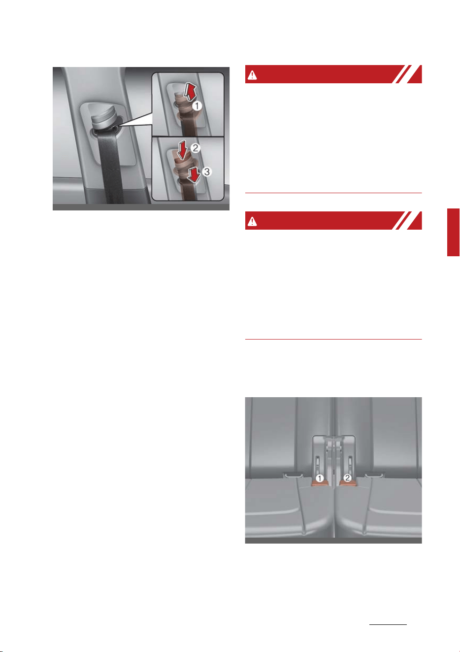
29
4
4
Safety features of your vehicle Seat belts
The height of the adjusting seat belt
should not be too close to your neck.
You will not be getting the most
effective protection. The shoulder
portion should be adjusted so that it
lies across your chest and midway
over your shoulder near the door
and not your neck.
To adjust the height of the seat belt
anchor, lower or raise the height
adjuster into an appropriate posi
-
tion.
䳜 To raise the height adjuster, pull it
up (1).
䳜 To lower it, push it down (3) while
pressing the height adjuster but
-
ton (2).
Release the button to lock the
anchor into position. Try sliding the
height adjuster to make sure that it
has locked into position.
Improperly positioned seat belts can
cause serious injuries in an accident.
WARNING
Shoulder belt positioning
Verify the shoulder belt anchor is
locked into position at the appropri
-
ate height. Never position the shoul
-
der belt across your neck or face.
Improperly positioned seat belts can
cause serious injuries in an accident.
WARNING
Seat belt replacement
Replace your seat belts after being
in an accident. Failure to replace
seat belts after an accident could
leave you with damaged seat belts
that will not provide protection in
the event of another collision.
The seat belt should be locked into
the buckle on each seat cushion to
be properly fastened.
ODEEV058027NR
OMQ4AH030070
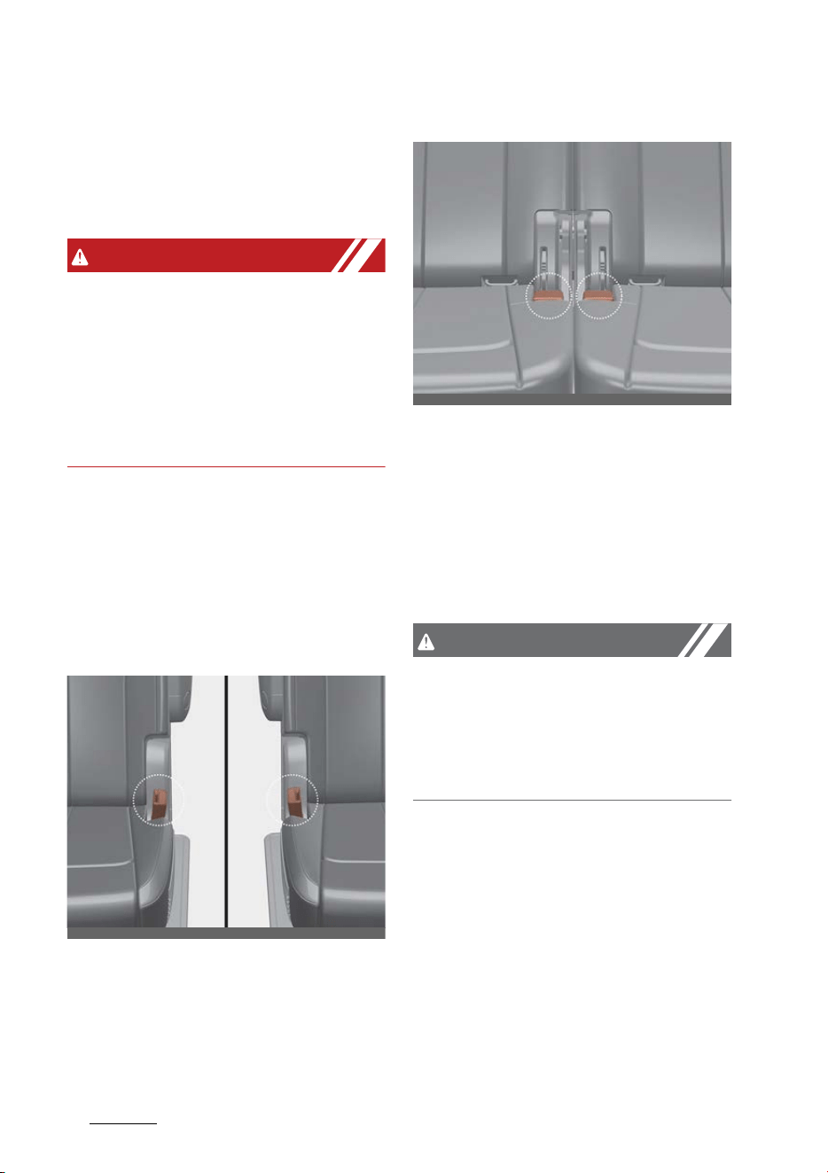
Safety features of your vehicle
304
Seat belts
1. Rear right seat belt fastening
buckle
2. Rear left seat belt fastening
buckle
WARNING
Prior to fastening the rear seat
belts, ensure the latch matches the
seat belt buckle. Forcefully fasten
-
ing the left or right seat belt to the
center buckle can result in an
improper fastening scenario that
will not protect you in an accident.
Stowing the rear seat belt
The rear seat belt buckles can be
stowed in the pocket between the
rear seatback and cushion when not
in use.
2nd row seat
3rd row seat
1. Route the seat belt webbing
through the rear seat belt guides.
It will help keep the belts from
being trapped behind or under the
seats.
2. After inserting the seat belt,
tighten the belt webbing by pull
-
ing it up.
CAUTION
When pulling out to wear the seat
belt, the tongue should be slowly
pulled out of the seat belt guide so
that the seat belt guide does not
come off the trim.
OMQ4AH030071
OMQ4AH030072
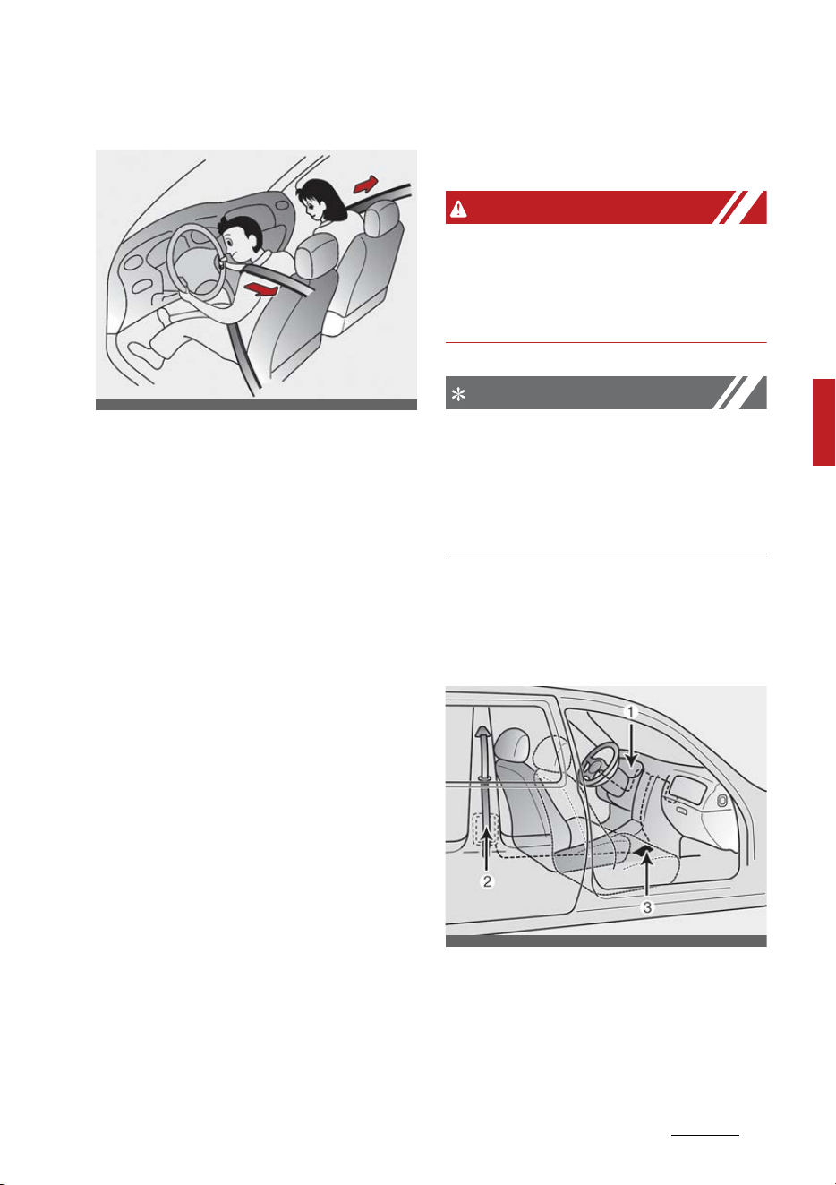
31
4
4
Safety features of your vehicle Seat belts
Pre-tensioner seat belt
Your vehicle is equipped with driver's
and front passenger's pre-tensioner
seat belts.
The purpose of the pre-tensioner is
to make sure that the seat belts fit
tightly against the occupant's body
in certain collisions.
The pre-tensioner seat belts may
be activated in crashes where the
collision is severe enough.
When the vehicle stops suddenly, or
if the occupant tries to lean forward
too quickly, the seat belt retractor
will lock into position. In certain
frontal collisions, the pre-tensioner
will activate and pull the seat belt
into tighter contact against the
occupant's body.
If the system senses excessive ten
-
sion on the driver or passenger's
seat belt when the pre-tensioner
system activates, the load limiter
inside the retractor pre-tensioner
will release some of the pressure on
the affected seat belt.
WARNING
For your safety, be sure that the
belt webbing is not loose or twisted
and always sit properly on your
seat.
NOTICE
The pre-tensioner may activate not
only in a frontal collision but also in a
side collision, if the vehicle is
equipped with a side or curtain air
bag.
The seat belt pre-tensioner system
consists mainly of the following
components. Their locations are
shown in the illustration:
1. SRS air bag warning light
2. Front retractor pre-tensioner
assembly
3. SRS control module
OON038092NR
OON039121NR
Safety features of your vehicle
324
Seat belts
WARNING
Skin irritation
Wash all exposed skin areas thor
-
oughly after an accident in which
the pre-tensioner seat belts were
activated. The fine dust from the
pre-tensioner activation may cause
skin irritation and should not be
inhaled for prolonged periods.
NOTICE
䳜 Both the driver's and front pas
-
senger's seat belt pre-tensioner
systems may be activated not
only in certain frontal collisions,
but also in certain side collisions
or rollovers, if the vehicle is
equipped with a side or curtain air
bag.
䳜 Because the sensor that activates
the SRS air bag is connected with
the pre-tensioner seat belt, the
SRS air bag warning light on
the instrument panel will illumi
-
nate for approximately 3~6 sec
-
onds after the ENGINE START/
STOP button has been turned to
the ON position, and then it should
turn off.
䳜 If the pre-tensioner seat belt sys
-
tem is not working properly, this
warning light will illuminate even
if there is not a malfunction with
the SRS air bag. If the SRS air bag
warning light does not illuminate
when the ENGINE START/STOP
button has been turned to the ON
position, or if it remains illumi
-
nated after illuminating for
approximately 3 ~ 6 seconds, or if
it illuminates while the vehicle is
being driven, have an authorized
Kia dealer inspect the pre-ten
-
sioner seat belt and SRS air bag
system as soon as possible.
NOTICE
Do not attempt to service or repair
the pre-tensioner seat belt system
in any manner. Do not attempt to
inspect or replace the pre-ten
-
sioner seat belts yourself. This must
be done by an authorized Kia dealer.
WARNING
Hot pre-tensioner
Do not touch the pre-tensioner seat
belt assemblies for several minutes
after they have been activated.
When the pre-tensioner seat belt
mechanism fires during a collision
the pre-tensioner becomes hot and
can burn you.
Pre-tensioners are designed to
operate only one time. After activa
-
tion, pre-tensioner seat belts must
be replaced. If the pre-tensioner
must be replaced, contact an autho
-
rized Kia dealer.

33
4
4
Safety features of your vehicle Seat belts
Seat belt precautions
Take the following precautions
when using seat belts.
Infant or small child
All 50 states have child restraint
laws. You should be aware of the
specific requirements in your state.
Child and/or infant seats must be
properly placed and installed in the
rear seat. For more information
about the use of these restraints,
refer to "Child Restraint System
(CRS)" on page 4-36.
NOTICE
Small children are best protected
from injury in an accident when
properly restrained in the rear seat
by a Child Restraint System that
meets the requirements of the Fed
-
eral Motor Vehicle Safety Standards
(FMVSS). Before buying any Child
Restraint System, make sure that it
has a label certifying that it meets
Federal Motor Vehicle Safety Stan
-
dard 213. The restraint must be
appropriate for your child's height
and weight. Check the label on the
child restraint for this information.
Refer to "Child Restraint System
(CRS)" on page 4-36.
Larger children
Children who are too large for Child
Restraint System should always
occupy the rear seat and use the
available lap/shoulder belts. The lap
portion should be fastened and snug
on the hips as low as possible. Check
periodically to insure that the belt
fits. A child's squirming could put the
belt out of position. Children are
given the most safety in the event
of an accident when they are
restrained by a proper restraint
system in the rear seat. If a larger
child (over age 13) must be seated
in the front seat, the child should be
securely restrained by the available
lap/shoulder belt and the seat
should be placed in the rearmost
position. Children age 13 and under
should be restrained securely in the
rear seat. NEVER place a child age
13 and under in the front seat.
NEVER place a rear facing child seat
in the front seat of a vehicle.
If the shoulder belt portion slightly
touches the child's neck or face, try
placing the child closer to the center
of the vehicle. If the shoulder belt
still touches their face or neck they
need to be returned to a Child
Restraint System.

Safety features of your vehicle
344
Seat belts
WARNING
Small children
Do not allow small children to ride in
the vehicle without an appropriate
Child Restraint System. If the shoul
-
der belt comes in contact with your
child's neck or face, your child is too
small to ride in the vehicle. In a
crash, the seat belt will inflict injury
to your child's neck, throat and face.
Restraint of pregnant women
Pregnant women should wear lap/
shoulder belt assemblies whenever
possible according to specific rec
-
ommendations by their doctors. The
lap portion of the belt should be
worn AS SECURELY AND LOW AS
POSSIBLE.
WARNING
Pregnant women
Pregnant women must never place
the lap portion of the seat belt
above or on the abdomen where the
fetus is located. The force of the
seat belt during a collision will crush
the fetus.
Injured person
A seat belt should be used when an
injured person is being transported.
When this is necessary, you should
consult a physician for recommen
-
dations.
One person per belt
Two people (including children)
should never attempt to use a single
seat belt. This could increase the
severity of injuries in case of an
accident.
Do not lie down
To reduce the chance of injuries in
the event of an accident and to
achieve maximum effectiveness of
the restraint system, all passengers
should be sitting up and the front
and rear seats should be in an
upright position when the vehicle is
moving. A seat belt cannot provide
proper protection if the person is
lying down in the rear seat or if the
front and rear seats are in a reclined
position.

35
4
4
Safety features of your vehicle Seat belts
Care of seat belts
Seat belt systems should never be
disassembled or modified. In addi
-
tion, care should be taken to assure
that seat belts and belt hardware
are not damaged by seat hinges,
doors or other abuse.
WARNING
Pinched seat belt
Make sure that the webbing and/or
buckle does not get caught or
pinched in the rear seat when
returning the rear seatback to its
upright position. A caught or pinched
webbing/buckle may become dam
-
aged and could fail during a collision
or sudden stop.
WARNING
Seatbelts can become hot in a vehi
-
cle that has been closed up in sunny
weather. Please handle with care, as
they could burn infants and children,
if used abruptly.
Periodic inspection
All seat belts should be inspected
periodically for wear or damage of
any kind. Any damaged parts should
be replaced as soon as possible.
Keep belts clean and dry
Seat belts should be kept clean and
dry. If belts become dirty, they can
be cleaned by using a mild soap
solution and warm water. Bleach,
dye, strong detergents or abrasives
should not be used because they
may damage and weaken the fabric.
When to replace seat belts
The entire in-use seat belt assem
-
bly or assemblies should be replaced
if the vehicle has been involved in an
accident. This should be done even if
no damage is visible. Additional
questions concerning seat belt
operation should be directed to an
authorized Kia dealer.

Safety features of your vehicle
364
Child Restraint System (CRS)
Child Restraint System (CRS)
Infants and younger children must
be restrained in an appropriate
rear-facing or forward-facing Child
Restraint System (CRS) that has
first been properly secured to the
rear seat of the vehicle.
Children always in the rear
Children under age 13 must always
ride in the rear seats and must
always be properly restrained to
minimize the risk of injury in an
accident, sudden stop or sudden
maneuver.
WARNING
Restraint Location
Never install a child or infant seat on
the front passenger's seat. A child
riding in the front passenger seat
can be forcefully struck by an inflat
-
ing airbag and get seriously injured.
WARNING
Hot Child Restraint
A Child Restraint System can
become very hot if it is left in a
closed vehicle on a sunny day. Be
sure to check the seat cover, buckles
and latches before placing a child in
the restraint system.
According to accident statistics,
children are safer when properly
restrained in the rear seats than in
the front seat. Even with air bags,
children can be seriously injured or
killed. Children too large for a child
restraint must use the seat belts
provided.
All 50 states have child restraint
laws which require children to travel
in approved child restraint devices.
The laws governing the age or
height/weight restrictions at which
seat belts can be used instead of
child restraints differs among
states, so you should be aware of
the specific requirements in your
state, and where you are traveling.
The CRS must be properly placed
and installed in the rear seat. You
must use a commercially available
CRS that meets the requirements of
the Federal Motor Vehicle Safety
Standards (FMVSS).
A CRS is generally designed to be
secured in a vehicle seat by lap belt
portion of a lap/shoulder belt, or by
a LATCH system in the rear seats of
the vehicle.

37
4
4
Safety features of your vehicle Child Restraint System (CRS)
Child Restraint System (CRS)
Infants and younger children must
be restrained in an appropriate
rear-facing or forward-facing CRS
that has first been properly secured
to the rear seat of the vehicle. Read
and comply with the instructions for
installation and use provided by the
manufacturer of the CRS.
Child Restraint Installation
An improperly secured child
restraint can increase the risk of
serious injury or death in an acci
-
dent. Always take the following pre
-
cautions when using a Child
Restraint System:
䳜 Always follow the Child Restraint
System manufacturer's instruc
-
tions for installation and use.
䳜 Always properly restrain your
child in the child restraint.
䳜 If the vehicle head restraint pre
-
vents proper installation of a child
seat (as described in the Child
Restraint System manual), the
head restraint of the respective
seating position shall be read
-
justed or entirely removed.
䳜 Do not use an infant carrier or a
child safety seat that "hooks"
over a seatback as it may not
provide adequate protection in an
accident.
䳜 A child restraint in the center
seating position may also contact
or push up against the safety belt
buckles, which can damage the
buckles and make them unusable
or unsafe. Always check that the
child restraint does not contact
any of the safety belt buckles.
Check the placement of the child
restraint regularly to make sure
that it has not shifted and come
into contact with any of the
safety belt buckles.
NOTICE
After an accident, have a Kia dealer
check the Child Restraint System,
seat belts, tether anchors and lower
anchors.
Selecting a CRS
When selecting a CRS for your child,
always:
䳜 Make sure the CRS has a label
certifying that it meets applicable
Federal Motor Vehicle Safety
Standards (FMVSS 213).
䳜 Select a child restraint based on
your child's height and weight.
The required label or the instruc
-
tions for use typically provide this
information.
䳜 Select a child restraint that fits
the vehicle seating position where
it will be used.
䳜 Read and comply with the warn
-
ings and instructions for installa
-
tion and use provided with the
CRS.
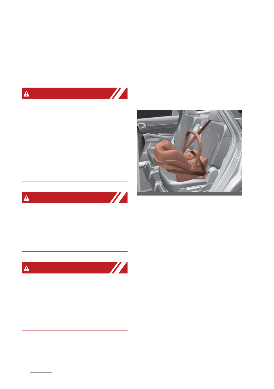
Safety features of your vehicle
384
Child Restraint System (CRS)
䳜 The American Academy of Pedi
-
atrics provides helpful fit and
safety information about child
restraints at www.healthychil
-
dren.org.
WARNING
Holding children
Never hold a child in your arms or
lap when riding in a vehicle. The vio
-
lent forces created during a crash
will tear the child from your arms
and throw the child against the car's
interior. Always use a Child Restraint
System which is appropriate for
your child's height and weight.
WARNING
Unattended children
Never leave children unattended in a
vehicle. The car can heat up very
quickly, resulting in injuries to the
child in the vehicle.
WARNING
Seat belt use
Do not use one seat belt for two
occupants at the same time. This
will eliminate any safety benefit
provided by the seat belt to the
occupants.
CRS types
There are three main types of the
CRS: rear-facing seats, forward-
facing seats, and booster seats.
They are classified according to the
child's age, height and weight.
Rear-facing child seats
A rear-facing child seat provides
restraint with the seating surface
against the back of the child. The
harness system holds the child in
place, and in an accident, acts to
keep the child positioned in the seat
and reduces the stress to the neck
and spinal cord.
All children under age one must
always ride in a rear-facing infant
child restraint.
Convertible and 3-in-1 child seats
typically have higher height and
weight limits for the rear-facing
position, allowing you to keep your
child rear-facing for a longer period
of time.
Continue to use a rear-facing child
seat for as long as your child will fit
within the height and weight limits
OMQ4AH030102
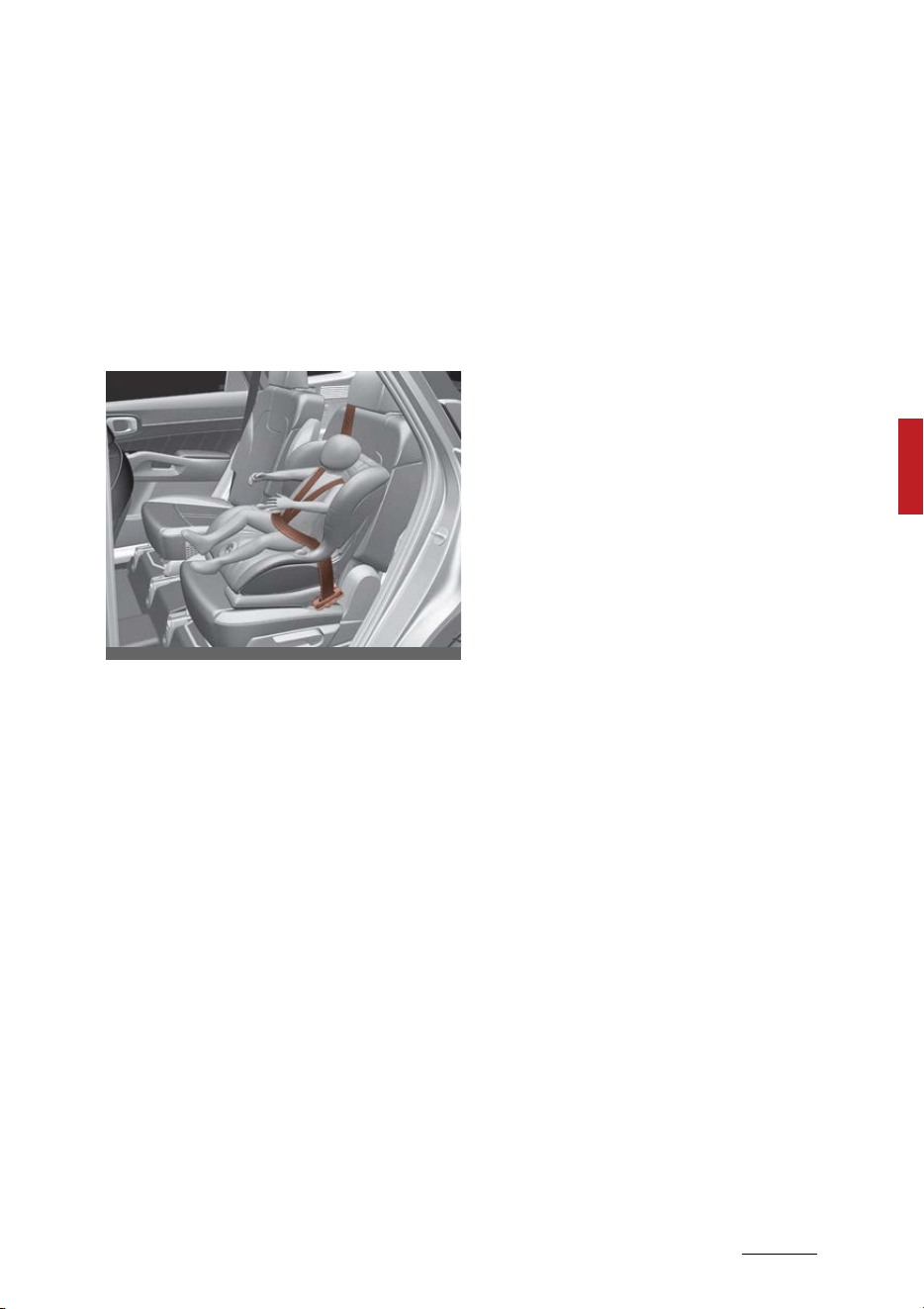
39
4
4
Safety features of your vehicle Child Restraint System (CRS)
allowed by the child seat manufac
-
turer. It's the best way to keep
them safe. Once your child has out
-
grown the rear-facing child
restraint, your child is ready for a
forward-facing child restraint with a
harness.
Forward-facing child restraints
A forward-facing child seat provides
restraint for the child's body with a
harness. Keep children in a forward-
facing child seat with a harness until
they reach the top height or weight
limit allowed by your child
restraint's manufacturer.
Once your child outgrows the for
-
ward-facing child restraint, your
child is ready for a booster seat.
Booster seats
A booster seat is a restraint
designed to improve the fit of the
vehicle's seat belt system. A booster
seat positions the seat belt so that
it fits properly over the lap of your
child.
Keep your child in a booster seat
until they are big enough to sit in
the seat without a booster and still
have the seat belt fit properly. For a
seat belt to fit properly, the lap belt
must lie snugly across the upper
thighs, not the stomach. The shoul
-
der belt should lie snug across the
shoulder and chest and not across
the neck or face. Children under age
13 must always ride in the rear
seats and must always be properly
restrained to minimize the risk of
injury.
Installing a CRS
After selecting a proper child seat
for your child, check to make sure it
fits properly in your vehicle.
Follow the instructions provided by
the manufacturer when installing
the child seat. Note these general
steps when installing the seat to
your vehicle:
䳜 Properly secure the child restraint
to the vehicle. All child restraints
must be secured to the vehicle
with the lap part of a lap/shoulder
belt or with the LATCH system.
䳜 Make sure the child restraint is
firmly secured. After installing a
child restraint to the vehicle, push
and pull the seat forward and
from side-to-side to verify that it
is securely attached to the seat. A
child restraint secured with a seat
belt should be installed as firmly
as possible. However, some side-
to-side movement can be
expected.
OMQ4AH030103
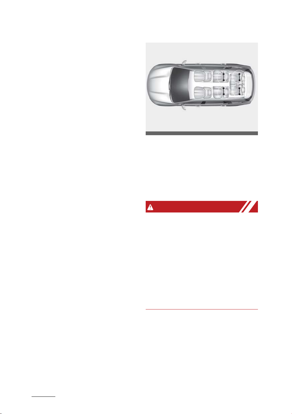
Safety features of your vehicle
404
Child Restraint System (CRS)
䳜 Secure the child in the child
restraint. Make sure the child is
properly strapped in the child
restraint according to the manu
-
facturer instructions.
Lower Anchors and Tether for Chil
-
dren (LATCH) system
The LATCH system holds a child
restraint during driving and in an
accident. This system is designed to
make installation of the child
restraint easier and reduce the pos
-
sibility of improperly installing your
child restraint. The LATCH system
uses anchors in the vehicle and
attachments on the child restraint.
The LATCH system eliminates the
need to use seat belts to secure the
child restraint to the rear seats.
Lower anchors are metal bars built
into the vehicle. There are two lower
anchors for each LATCH seating
position that will accommodate a
child restraint with lower attach
-
ments.
To use the LATCH system in your
vehicle, you must have a child
restraint with LATCH attachments.
The child seat manufacturer will
provide you with instructions on
how to use the child seat with its
attachments for the LATCH lower
anchors.
LATCH anchors have been provided
in the left and right outboard rear
seating positions. Their locations are
shown in the illustration. There are
no LATCH anchors provided for the
center rear seating position.
WARNING
LATCH Lower Anchors
Never attempt to attach a LATCH
equipped seat in the center seating
position. LATCH lower anchors are
only to be used in the left and right
rear outboard seating positions. You
may damage the anchors or the
anchors may fail and break in a colli
-
sion if the seat is in the center seat
-
ing position.
The lower anchor position indicator
symbols are located on the left and
right rear seatbacks to identify the
position of the lower anchors in
your vehicle (see arrows in illustra
-
tion).
OMQ4AH030043
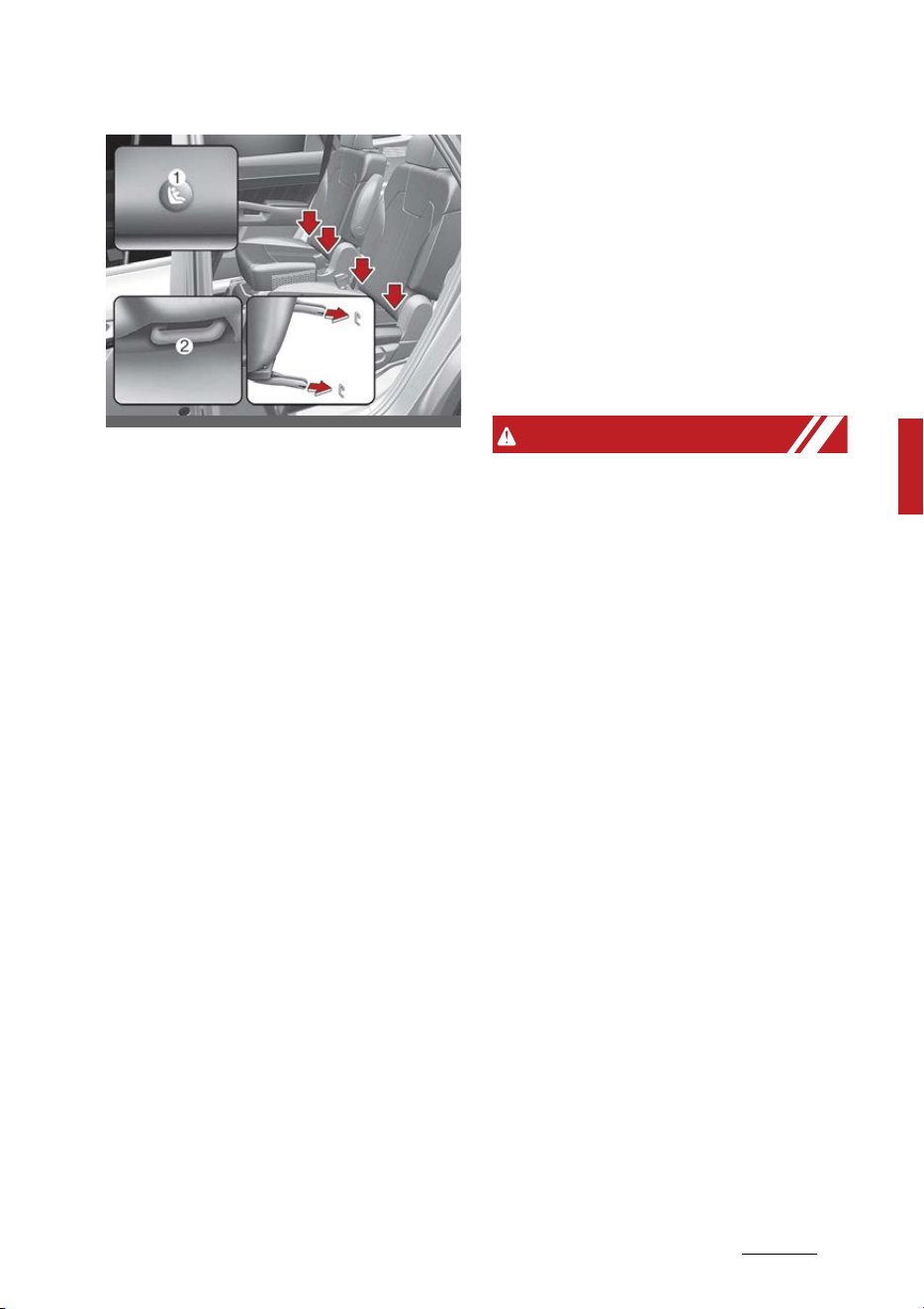
41
4
4
Safety features of your vehicle Child Restraint System (CRS)
1. Lower Anchor position indicator
2. Lower Anchor
The LATCH anchors are located
between the seatback and the seat
cushion of the rear seat left and
right outboard seating positions.
To use the lower anchor, push the
upper portion of the lower anchor
cover.
Securing a child restraint with the
LATCH anchors system
To install a LATCH-compatible child
restraint in either of the rear out
-
board seating positions:
1. Move the seat belt buckle away
from the lower anchors. Other
-
wise, the webbing or buckle can
be damaged by the latch anchor,
which can make them become
unusable or unsafe.
2. Move any other objects away
from the anchors that could pre
-
vent a secure connection between
the child restraint and the lower
anchors.
3. Place the child restraint on the
vehicle seat, then attach the seat
to the lower anchors according to
the instructions provided by the
child restraint manufacturer.
4. Follow the child restraint instruc
-
tions for properly adjusting and
tightening the lower attach
-
ments on the child restraint to
the lower anchors.
WARNING
Take the following precautions
when using the LATCH system:
䳜 Read and follow all installation
instructions provided with your
Child Restraint System.
䳜 To prevent the child from reaching
and taking hold of the unused
seat belts, buckle all unused rear
seat belts before the child is
placed into the vehicle. Lock each
unused seatbelt following the
instructions in the "automatic
locking mode" subsection, and
place the webbing behind the child
seat or against an unused seat
-
back. Children can be strangled if
a shoulder belt becomes wrapped
around their neck and the seat
belt tightens.
䳜 NEVER attach more than one child
restraint to a single anchor. This
could cause the anchor or attach
-
ment to come loose or break.
OMQ4AH030044
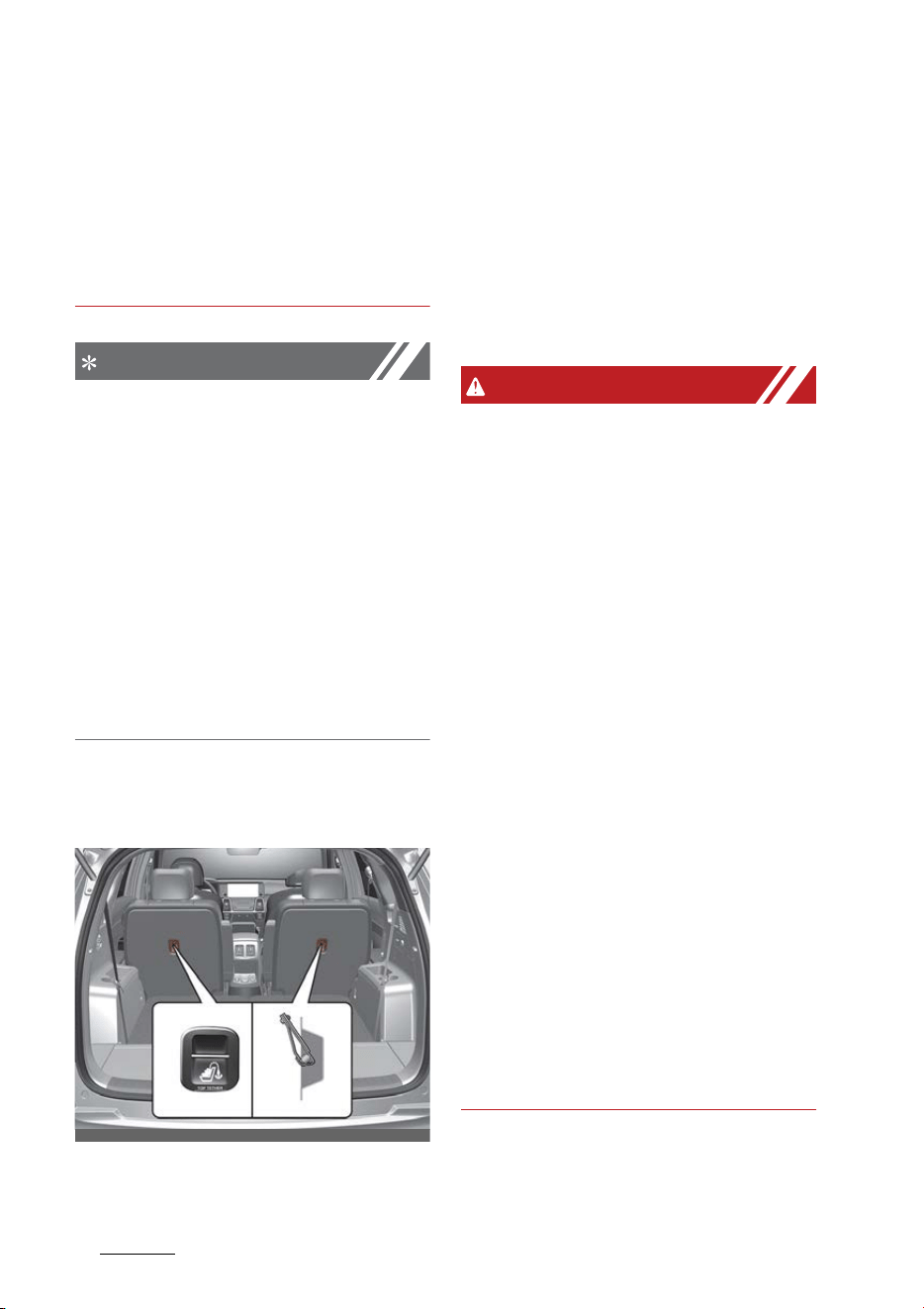
Safety features of your vehicle
424
Child Restraint System (CRS)
䳜 Always have the LATCH system
inspected by your authorized Kia
dealer after an accident. An acci
-
dent can damage the LATCH sys
-
tem and may not properly secure
the child restraint.
NOTICE
The recommended maximum
weight for the LATCH system is 65
lbs. (30 kg). When selecting a proper
child restraint, consider that the
maximum total weight of the child
plus the child restraint should be
less than 65 lbs. (30 kg). As a guide,
the MAX child restraint weight
should be determined by the follow
-
ing calculation: Child Restraint
Weight = 65 - (child's total weight in
lbs.)
Securing a child restraint seat with
"Tether Anchor" system
First secure the child restraint with
the LATCH lower anchors or the
seat belt. If the child restraint man
-
ufacturer recommends that the top
tether strap be attached, attach
and tighten the top tether strap to
the top tether strap anchor.
Child Restraint hook holders are
located on the seat back.
WARNING
Take the following precautions
when installing the tether strap:
䳜 Read and follow all installation
instructions provided with your
Child Restraint System.
䳜 NEVER attach more than one child
restraint to a single tether anchor.
This could cause the anchor or
attachment to come loose or
break.
䳜 Do not attach the tether strap to
anything other than the correct
tether anchor. It may not work
properly if attached to something
else.
䳜 Do not use the tether anchors for
adult seat belts or harnesses, or
for attaching other items or
equipment to the vehicle.
䳜 Always fasten the seat belts
behind the child restraint seat
when they are not used to secure
the child seat. Failure to do so
may result in child strangulation.
To install the tether anchor:
OMQ4AH030042
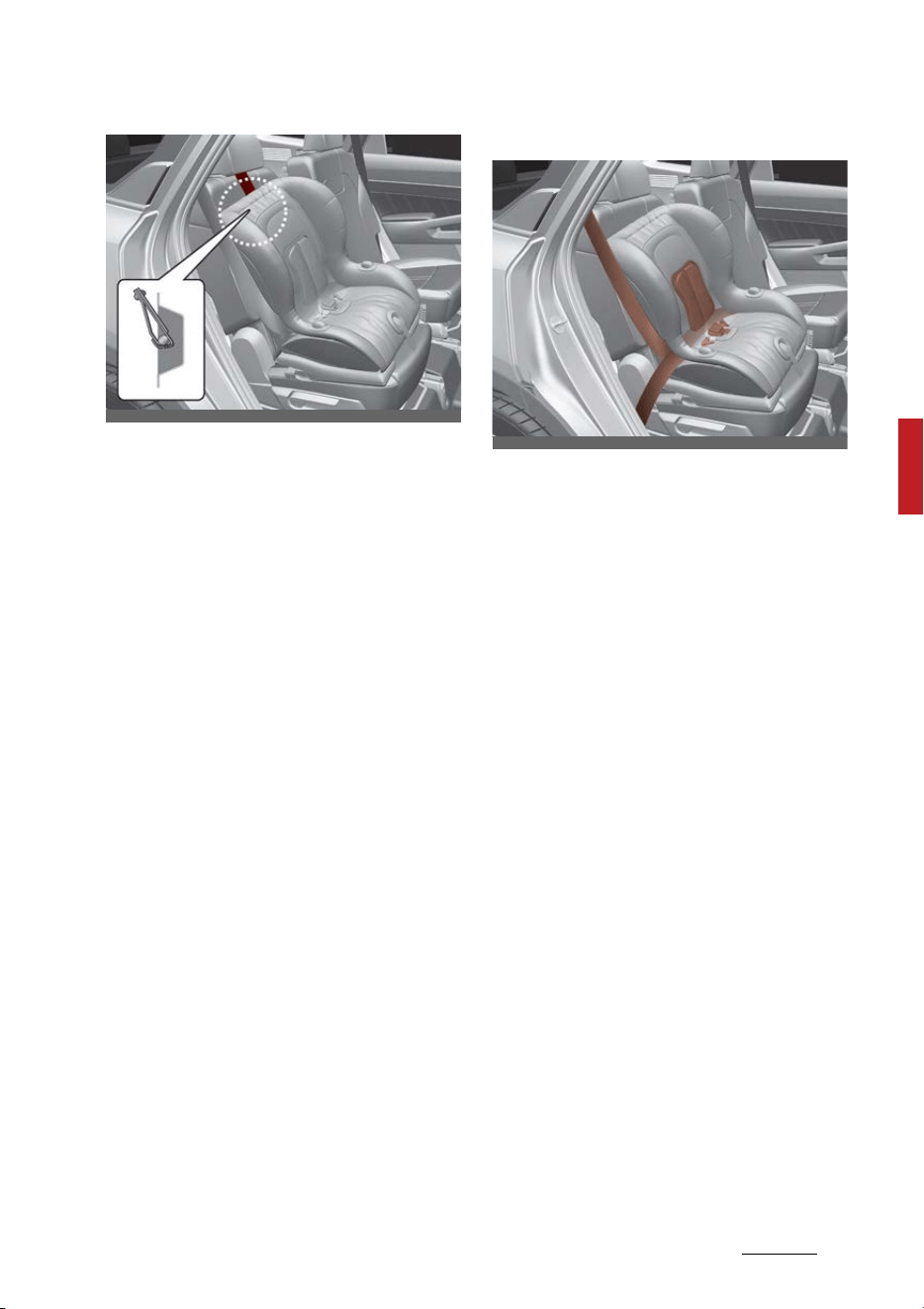
43
4
4
Safety features of your vehicle Child Restraint System (CRS)
1. Route the Child Restraint System
seat strap over the seatback.
For vehicles with adjustable head
-
rest, route the tether strap under
the headrest and between the
headrest posts, otherwise route
the tether strap over the top of
the seatback.
2. Connect the top-tether to the
top-tether anchorage, then
tighten the top-tether according
to the instructions of your Child
Restraint System's manufacturer
to firmly attach the Child
Restraint System to the seat.
3. Check that the child restraint is
securely attached to the seat by
pushing and pulling the seat for
-
ward and from side-to-side.
Securing a child restraint with a
lap/shoulder belt
When not using the LATCH system,
all child restraints must be secured
to a vehicle rear seat with the lap
part of a lap/shoulder belt.
Automatic locking mode
All passenger seat belts move freely
under normal conditions and only
lock under extreme or emergency
conditions (emergency locking
mode). So, in order to secure a child
restraint, you must manually pull
the seat belt all the way out to shift
the retractor to the "automatic
locking" mode.
The "automatic locking" mode will
help prevent the normal movement
of the child in the vehicle from caus
-
ing the seat belt to loosen and com
-
promise the CRS.
To install a CRS on the rear seats, do
the following:
1. Place the CRS on a rear seat and
route the lap/shoulder belt
around or through the child
restraint, following the restraint
manufacturer's instructions.
Be sure the seat belt webbing is
not twisted.
2. Fasten the lap/shoulder belt latch
into the buckle. Listen for the dis
-
tinct "click" sound.
OMQ4AH030104
OMQ4AH030105
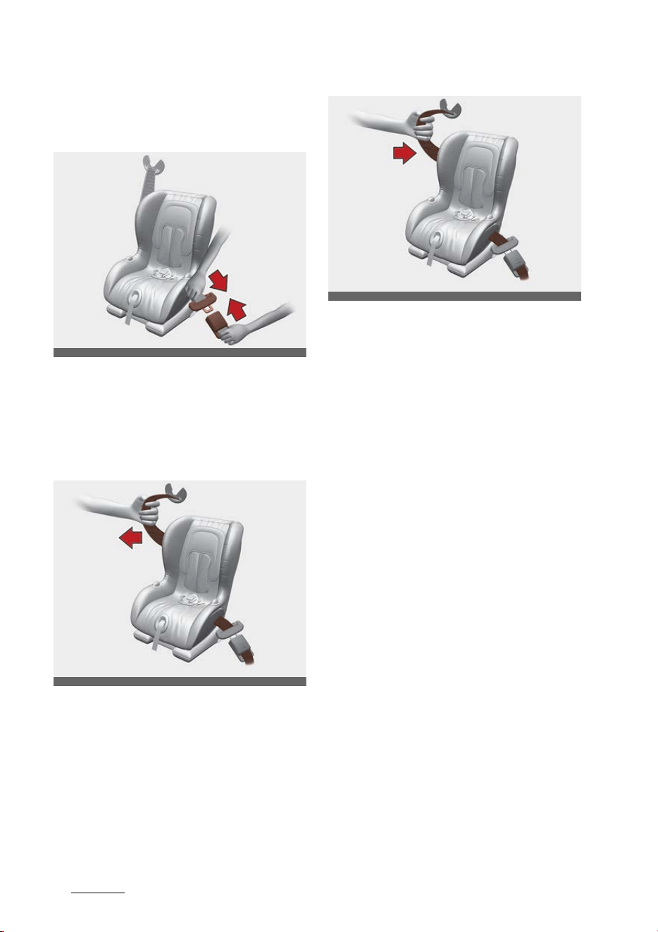
Safety features of your vehicle
444
Child Restraint System (CRS)
Position the release button so
that it is easy to access in case of
an emergency.
3. Pull the shoulder portion of the
seat belt all the way out. When
the shoulder portion of the seat
belt is fully extended, it will shift
the retractor to the "automatic
locking" (child restraint) mode.
4. Slowly allow the shoulder portion
of the seat belt to retract and lis
-
ten for an audible "clicking" or
"ratcheting" sound. This indicates
that the retractor is in the "auto
-
matic locking" mode. If no distinct
sound is heard, repeat steps 3 and
4.
5. Remove as much slack from the
belt as possible by pushing down
on the CRS while feeding the
shoulder belt back into the
retractor.
ODEEV058042NR
ODEEV058043NR
ODEEV058044NR

45
4
4
Safety features of your vehicle Child Restraint System (CRS)
6. Push and pull on the CRS to con
-
firm that the seat belt is holding it
firmly in place. If it is not, release
the seat belt and repeat steps 2
through 6.
7. Double check that the retractor is
in the "automatic locking" mode
by attempting to pull more of the
seat belt out of the retractor. If
you cannot, the retractor is in the
"automatic locking" mode.
If your CRS manufacturer instructs
or recommends you to use a tether
anchor with the lap/shoulder belt,
refer to "Securing a child restraint
seat with "Tether Anchor" system"
on page 4-42 for more information.
NOTICE
When the seat belt is allowed to
retract to its fully stowed position,
the retractor will automatically
switch from the "automatic locking"
mode to the emergency lock mode
for normal adult usage.
WARNING
Auto lock mode
Set the retractor to Automatic Lock
mode when installing any Child
Restraint System. If the retractor is
not in the automatic locking mode,
the child restraint can move when
your vehicle turns or stops sud
-
denly. A child can be seriously
injured or killed if the child restraint
is not properly anchored in the car.
To remove the child restraint, press
the release button on the buckle
and then pull the lap/shoulder belt
out of the restraint and allow the
seat belt to retract fully.
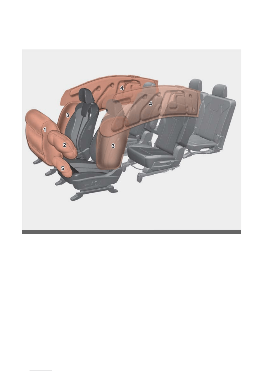
Safety features of your vehicle
464
Air bag - Advanced Supplemental Restraint
System
Air bag - Advanced Supplemental Restraint System
* The actual air bags in the vehicle may differ from the illustration.
1. Passenger's front air bag
2. Driver's front air bag
3. Side air bag
4. Curtain air bag
5. Driver's knee air bag
Even in vehicles with air bags, you and your passengers must always wear
the safety belts provided in order to minimize the risk and severity of injury
in the event of a collision or rollover.
OMQ4AH030069

47
4
4
Safety features of your vehicle Air bag - Advanced Supplemental Restraint
System
How does the air bag system oper
-
ate
䳜 Air bags are activated (able to
inflate if necessary) only when
the ENGINE START/STOP Button
is in the ON Position and it can be
activated within about 3 minutes
after vehicle off.
䳜 The appropriate air bags inflate
instantly in the event of a serious
frontal collision or side collision in
order to help protect the occu
-
pants from serious physical
injury.
䳜 There is no single speed at which
the air bags will inflate. Generally,
air bags are designed to inflate
based upon the severity of a colli
-
sion and its direction, etc. Several
factors determine whether the
sensors produce an electronic
deployment/inflation signal.
䳜 Air bags will not deploy in every
crash or collision situations. Air
bag deployment depends on a
number of factors including vehi
-
cle speed, angles of impact, and,
the density and stiffness of the
vehicles or objects which your
vehicle hits in the collision. The
determining factors are not lim
-
ited to those mentioned above.
䳜 The front air bags will completely
inflate and deflate in an instant. It
is virtually impossible for you to
see the air bags inflate during an
accident. It is much more likely
that you will simply see the
deflated air bags hanging out of
their storage compartments after
the collision.
䳜 In addition to inflating in serious
side collisions, side and/or curtain
air bags will inflate if the sensing
system detects a rollover.
䳜 When a rollover is detected, side
and/or curtain airbags will remain
inflated longer. This helps provide
protection from ejection, espe
-
cially when used in conjunction
with the seat belts.
䳜 In order to help provide protec
-
tion, the air bags must inflate
rapidly. The airbag inflates
extremely fast between the
occupant and the vehicle struc
-
tures before the occupant
impacts the vehicle structures.
This speed of inflation reduces
the risk of serious or life-threat
-
ening injuries and is thus a neces
-
sary part of the air bag design.
However, airbag inflation can also
cause injuries which can include
facial abrasions, bruises and bro
-
ken bones. This is because the
rapid inflation also causes the air
-
bags to expand with a great deal
of force.

Safety features of your vehicle
484
Air bag - Advanced Supplemental Restraint
System
䳜 There are even circumstances
under which contact with the
steering wheel or passenger air
bag can cause fatal injuries, espe
-
cially if the occupant is positioned
excessively close to the steering
wheel or passenger air bag.
WARNING
Airbag inflation
Sit as far back as possible from the
steering wheel while still maintain
-
ing comfortable control of the vehi
-
cle. A distance of at least 10 inches
(25 cm) from your chest to the
steering wheel is recommended.
Failure to do so can result in airbag
inflation injuries to the driver.
Noise and smoke
When inflated, the air bags make a
loud noise and leave smoke and
powder in the air inside the vehicle.
This is normal and is a result of the
vehicle of the air bag inflator. After
the air bag inflates, you may feel
substantial discomfort in breathing
due to the contact of your chest
with both the seat belt and the air
bag, as well as from breathing the
smoke and powder. Open your doors
and/or windows as soon as possible
after impact in order to reduce dis
-
comfort and prevent prolonged
exposure to the smoke and powder.
Though smoke and powder are non
-
toxic, it may cause irritation to the
skin (eyes, nose and throat, etc). If
this is the case, wash and rinse with
cold water immediately and consult
a doctor if the symptom persists.
WARNING
Hot components
Do not touch the air bag storage
area's internal components immedi
-
ately after airbag inflation. The air
bag related parts in the steering
wheel, instrument panel and the
roof rails above the front and rear
doors are very hot. Hot components
can result in burn injuries.
WARNING
Do not install or place any accesso
-
ries near air bag deployment areas,
such as the instrument panel, win
-
dows, pillars, and roof rails.
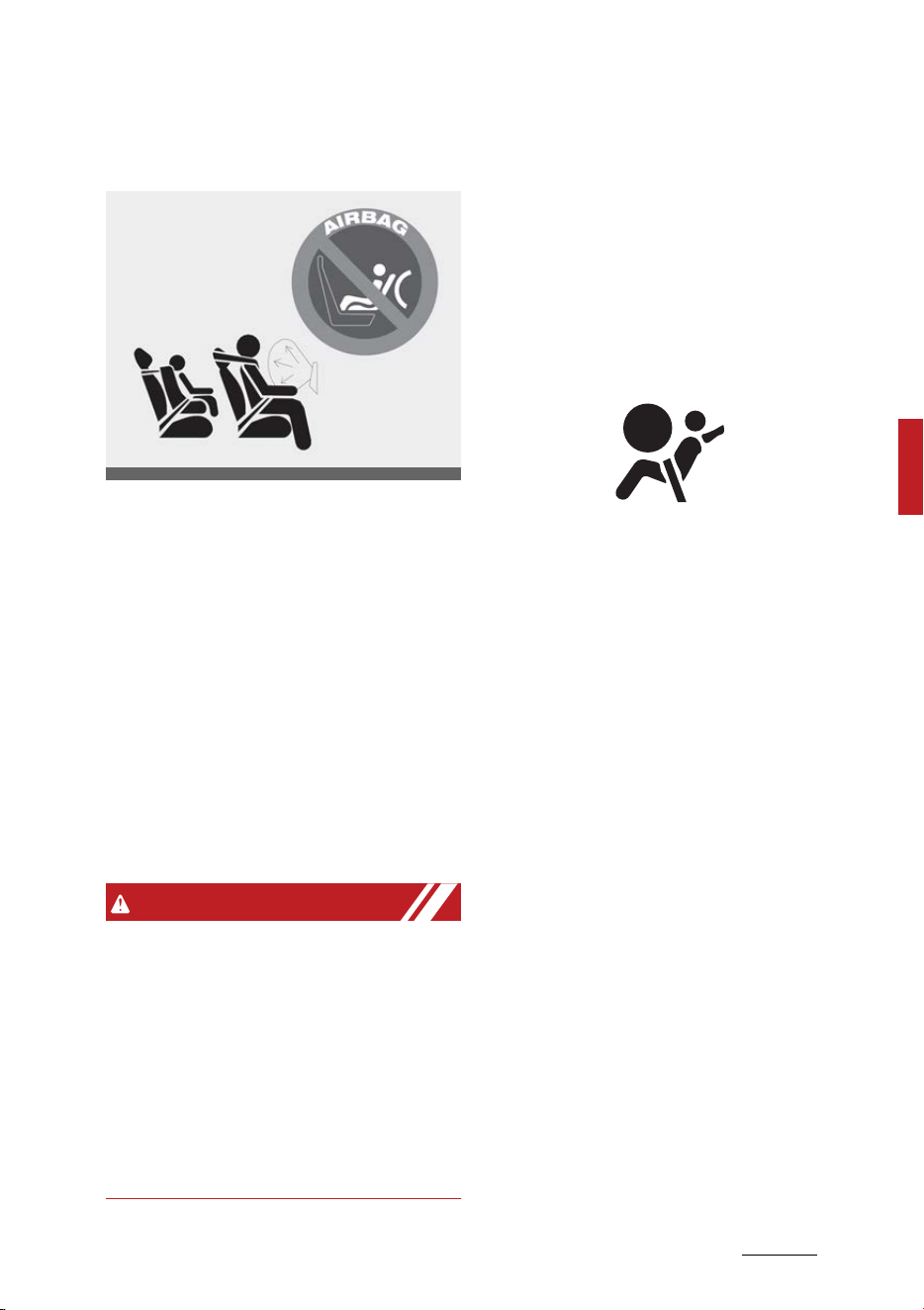
49
4
4
Safety features of your vehicle Air bag - Advanced Supplemental Restraint
System
Do not install a child restraint on
the front passenger's seat
Never place a rear-facing child
restraint in the front passenger's
seat.
If the air bag deploys, it would
impact the rear-facing child
restraint, causing serious or fatal
injury.
In addition, do not place front-facing
child restraints in the front passen
-
ger's seat. If the front passenger air
bag inflates, it could cause serious
or fatal injuries to the child.
WARNING
Air bag deployment
When children are seated in the rear
outboard seats of a vehicle equipped
with side and/or curtain air bags,
install the Child Restraint System as
far away from the door side as pos
-
sible. Inflation of the side and/or
curtain air bags could impact the
child.
Air bag warning and indicator
Air bag warning light
The purpose of air bag warning light
in your instrument panel is to alert
you of a potential problem with
your air bag system, which could
include your side and/or curtain air
bags used for rollover protection.
If the air bag warning light is illumi
-
nated for more than 6 seconds after
the ENGINE START/STOP button has
been turned to the ON position, or if
it illuminates during vehicle opera
-
tion, an SRS component may not be
functioning properly and you should
have your vehicle checked by an
authorized Kia dealer.
If any of the following conditions
occur, this indicates a malfunction in
the air bag system. Have an autho
-
rized Kia dealer inspect the air bag
system as soon as possible.
䳜 The light does not turn on briefly
when you turn the ENGINE
START/STOP button to the ON
position.
䳜 The light stays on after illuminat
-
ing for approximately 3 ~ 6 sec
-
onds.
䳜 The light comes on while the vehi
-
cle is in motion.
ODEEV058046NR
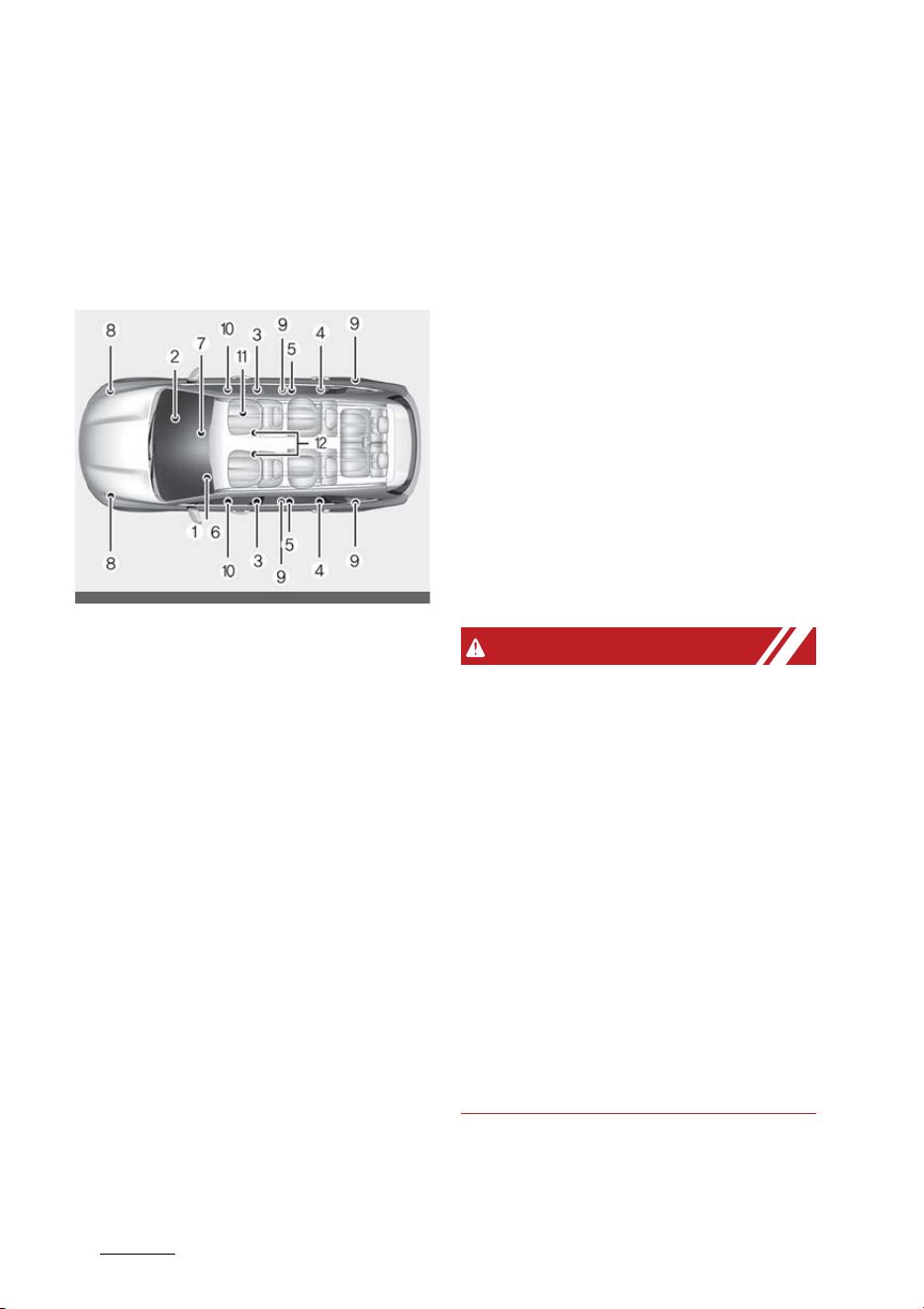
Safety features of your vehicle
504
Air bag - Advanced Supplemental Restraint
System
䳜 The light blinks when the ENGINE
START/STOP button to the ON
position.
Supplemental Restraint System
(SRS) components and functions
* The actual position of SRS compo
-
nents may differ from the illus
-
tration.
The SRS consists of the following
components:
1. Driver's front air bag module
2. Passenger's front air bag module
3. Side air bag modules
4. Curtain air bag modules
5. Retractor pre-tensioner assem
-
blies
6. Air bag warning light
7. SRS control module (SRSCM)/roll
-
over sensor
8. Front impact sensors
9. Side impact sensors
10.Side pressure sensors
11.Occupant Detection System
12.Front driver/passenger's seat
belt buckle sensor
The SRSCM continually monitors all
elements while the ENGINE START/
STOP Button is in the ON Position or
approximately within 3 minutes
after vehicle off to determine if a
frontal, near-frontal impact or side
impact is severe enough to require
air bag deployment or pre-tensioner
seat belt deployment.
The SRS air bag warning light on the
instrument panel will illuminate for
about 3 ~ 6 seconds after the
ENGINE START/STOP button is
turned to the ON position, after
which the air bag warning light
should go out.
WARNING
If any of the following conditions
occurs, this indicates a malfunction
of the SRS. In this case, have the
system inspected by an authorized
Kia dealer.
䳜 The light does not turn on briefly
when you turn the ENGINE
START/STOP button ON.
䳜 The light stays on after illuminat
-
ing for approximately 6 seconds.
䳜 The light comes on while the vehi
-
cle is in motion.
䳜 The light blinks when the ENGINE
START/STOP button is in ON posi
-
tion.
OMQ4AH030068
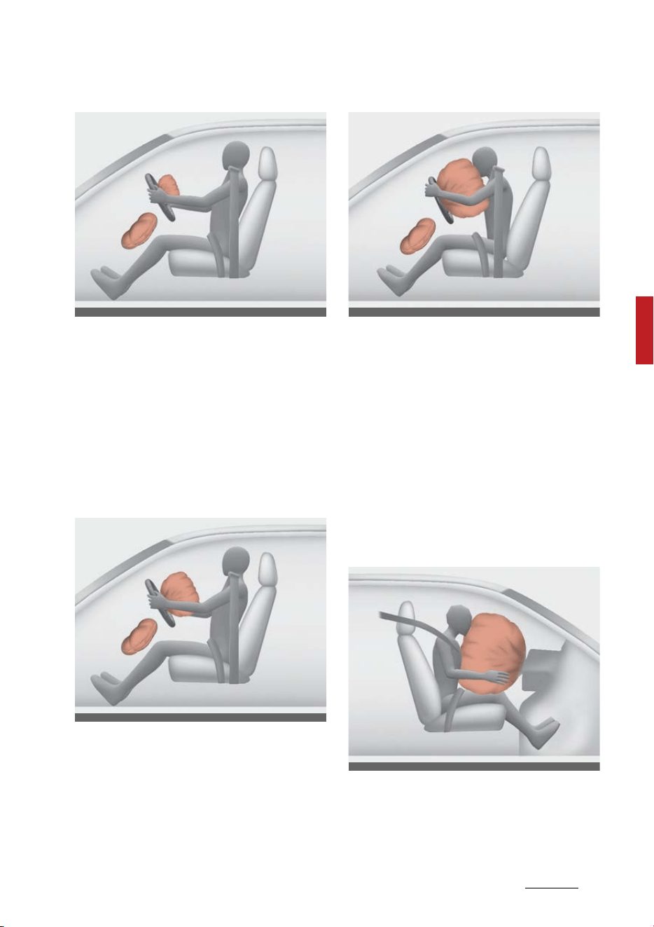
51
4
4
Safety features of your vehicle Air bag - Advanced Supplemental Restraint
System
Driver's front air bag (1)
The air bag modules are located
both in the center of the steering
wheel and in the front passenger's
panel above the glove box. When the
SRSCM detects a sufficiently severe
impact to the front of the vehicle, it
will automatically deploy the front
air bags.
Driver's front air bag (2)
Upon deployment, tear seams
molded directly into the pad covers
will separate under pressure from
the expansion of the air bags. Fur
-
ther opening of the covers then
allows full inflation of the air bags.
Driver's front air bag (3)
A fully inflated air bag, in combina
-
tion with a properly worn seat belt,
slows the driver's or the passenger's
forward motion, reducing the risk of
head and chest injury.
After complete inflation, the air bag
immediately starts deflating,
enabling the driver to maintain for
-
ward visibility and the ability to
steer or operate other controls.
Passenger's front air bag
OMQ4A030341
OMQ4A030342
OMQ4A030340
ODEEV058051NR

Safety features of your vehicle
524
Air bag - Advanced Supplemental Restraint
System
WARNING
Air bag obstructions
Do not install or place any accesso
-
ries on the steering wheel, instru
-
ment panel, or on the front
passenger's panel above the glove
box in a vehicle. Such objects may
become dangerous projectiles if the
air bag deploys.
WARNING
Flying objects
Do not place any objects (an
umbrella, bag, etc.) between the
front door and the front seat. Such
objects may become dangerous
projectiles if the side airbag inflates.
䳜 If an air bag deploys, there may
be a loud noise followed by a fine
dust released in the vehicle. These
conditions are normal and are not
hazardous - the air bags are
packed in this fine powder. The
dust generated during air bag
deployment may cause skin or
eye irritation as well as aggravate
asthma for some persons. Always
wash all exposed skin areas thor
-
oughly with cold water and a mild
soap after an accident in which
the air bags were deployed.
䳜 The SRS can function only when
the ENGINE START/STOP button
is in the ON Position or approxi
-
mately within 3 minutes after
vehicle off. The SRS is not working
properly if any of the following
situations occur :
- the SRS airbag warning light
does not illuminate
- the SRS airbag warning light
remains on continuously after
illuminating for about 3~6 sec
-
onds when the ENGINE START/
STOP button is turned to the
ON position or after the vehicle
is in ready mode
- the SRS airbag warning light
comes on while driving
If this occurs, have your vehicle
immediately inspected by an
authorized Kia dealer.
NOTICE
Before you replace a fuse or discon
-
nect a battery terminal, turn the
ENGINE START/STOP button to the
OFF position. Never remove or
replace the air bag related fuse(s)
when the ENGINE START/STOP but
-
ton is ON position. Failure to heed
this warning will cause the SRS air
bag warning light to illuminate.
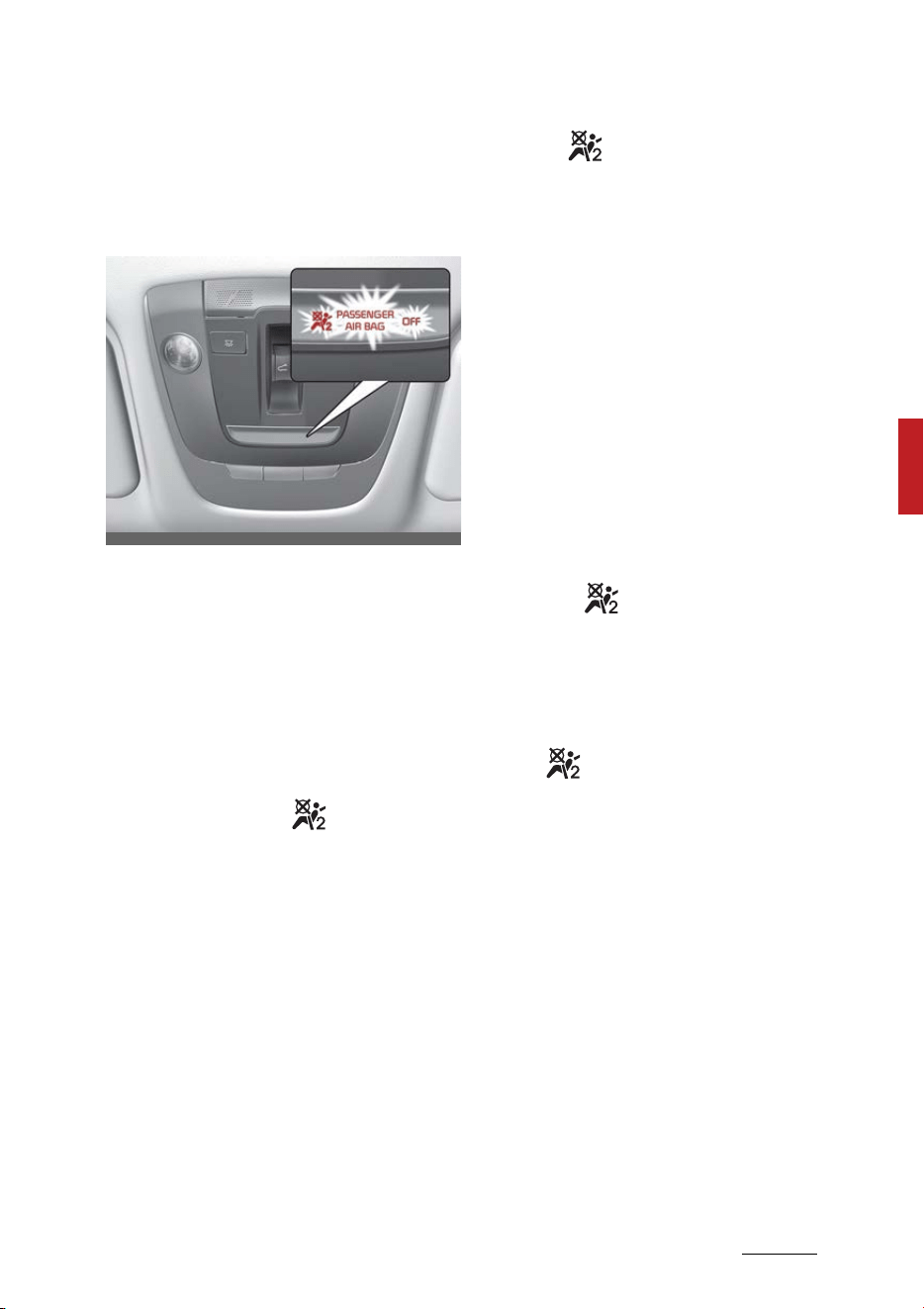
53
4
4
Safety features of your vehicle Air bag - Advanced Supplemental Restraint
System
Occupant Detection System (ODS)
Your vehicle is equipped with an
Occupant Detection System (ODS) in
the front passenger's seat.
The ODS is designed to detect the
presence of a properly-seated front
passenger and determine if the
passenger's front air bag should be
enabled (may inflate) or not. Only
the front passenger front air bag is
controlled by the ODS.
Do not put anything in front of the
passenger air bag ( ) indicator.
Main components of the ODS
䳜 A detection device is located
within the front passenger seat
cushion.
䳜 An electronic system determines
whether the passenger air bag
systems should be activated or
deactivated.
䳜 An indicator light located on the
overhead console which illumi
-
nates the words PASSENGER AIR
BAG ( ) indicates the front pas
-
senger air bag system is deacti
-
vated.
䳜 The overhead console air bag
warning light is interconnected
with the ODS.
If the front passenger seat is occu
-
pied by a person that the system
determines to be of appropriate
size, and he/she sits properly (sit
-
ting upright with the seatback in an
upright position, centered on the
seat cushion with their seat belt on,
legs comfortably extended and their
feet on the floor), the PASSENGER
AIR BAG ( ) indicator will turn off
and the front passenger's air bag
will be able to inflate, if necessary,
in frontal crashes.
You will find the PASSENGER AIR
BAG ( ) indicator on the overhead
console. This system detects the
conditions 1~4 in the following table
and activates or deactivates the
front passenger air bag based on
these conditions.
Always be sure that you and all
vehicle occupants are seated and
restrained properly (sitting upright
with the seat in an upright position,
centered on the seat cushion, with
the person's legs comfortably
extended, feet on the floor, and
wearing the safety belt properly)
OMQ4041589N

Safety features of your vehicle
544
Air bag - Advanced Supplemental Restraint
System
for the most effective protection by
the air bag and the safety belt.
The ODS may not function properly
if the passenger takes actions which
can defeat the detection system.
These include:
䳜 Failing to sit in an upright position.
䳜 Leaning against the door or cen
-
ter console.
䳜 Sitting towards the sides or the
front of the seat.
䳜 Putting legs on the dashboard or
resting them on other locations
which reduce the passenger
weight on the front seat.
䳜 Improperly wearing the safety
belt.
䳜 Reclining the seatback.

55
4
4
Safety features of your vehicle Air bag - Advanced Supplemental Restraint
System
Conditions and operation of the front passenger ODS
* 1. The system judges a person of adult size as an adult. When a smaller
adult sits in the front passenger seat, the system may recognize him/her
as a child depending on his/her physique and posture.
* 2. Do not allow children to ride in the front passenger seat. When a larger
child who has outgrown a CRS sits in the front passenger seat, the system
may recognize him/her as an adult depending upon his/her physique or
sitting position.
* 3. Never install a CRS on the front passenger seat.
* 4. The PASSENGER AIR BAG ( ) indicator may turn on or off when a child
above 12 months to 12 years old (with or without a CRS) sits in the front
passenger seat. This is a normal condition.
Condition detected by the
occupant classification sys
-
tem
Indicator/Warning light Devices
"PASSENGER
AIR BAG OFF"
indicator light
SRS warning
light
Front passenger
air bag
1. Adult
*1
Off Off Activated
2. Child Restraint System
(CRS) with child under 12
months old
*2*3*4
On Off Deactivated
3. Unoccupied On Off Deactivated
4. Malfunction in the system Off On Activated
Safety features of your vehicle
564
Air bag - Advanced Supplemental Restraint
System
WARNING
䳜 Do not install a child restraint seat
in the passenger seat when the
seat is heavily soaked with any
type of liquid.
䳜 Do not alter or remodel the Occu
-
pant Detection System (ODS).
This may damage the system and
prevent its proper function in a
collision.
NOTICE
䳜 Do not use car seat cushions that
cover up the surface of the seat
and aftermarket manufactured
passenger seat heaters.
䳜 After conducting car interior
cleaning using steam or deter
-
gent, the seat should be dried
properly. Afterward, check for
normal operation of the PASSEN
-
GER AIR BAG "OFF" and air bag
warning lights.
䳜 Any service related to the pas
-
senger seat and the ODS must be
done at an authorized Kia dealer
-
ship.
䳜 After the passenger seat has
been removed or installed for
repair purposes, check for normal
operation of the PASSENGER AIR
BAG ( ) and air bag warning
lights with a person seated or not
seated in the passenger seat.
NOTICE
When the PASSENGER AIR BAG ( )
symbol is illuminated, the passenger
air bag system will not operate. The
passenger air bag system will oper
-
ate when necessary if the symbol is
not illuminated.
NOTICE
Do not modify or replace the front
passenger seat. Don't place any
-
thing on or attach anything such as
a blanket, front seat cover or after
-
market seat heater to the front
passenger seat. This can adversely
affect the Occupant Detection Sys
-
tem.
WARNING
Occupant Detection System
Riding in an improper position
adversely affects the Occupant
Detection System and may result in
the deactivation of the front pas
-
senger airbag. It is important for the
driver to instruct the passenger as
to the proper seating instructions as
contained in this manual.
䳜 Do not place a heavy load in the
front passenger seatback pocket
or on the front passenger seat.
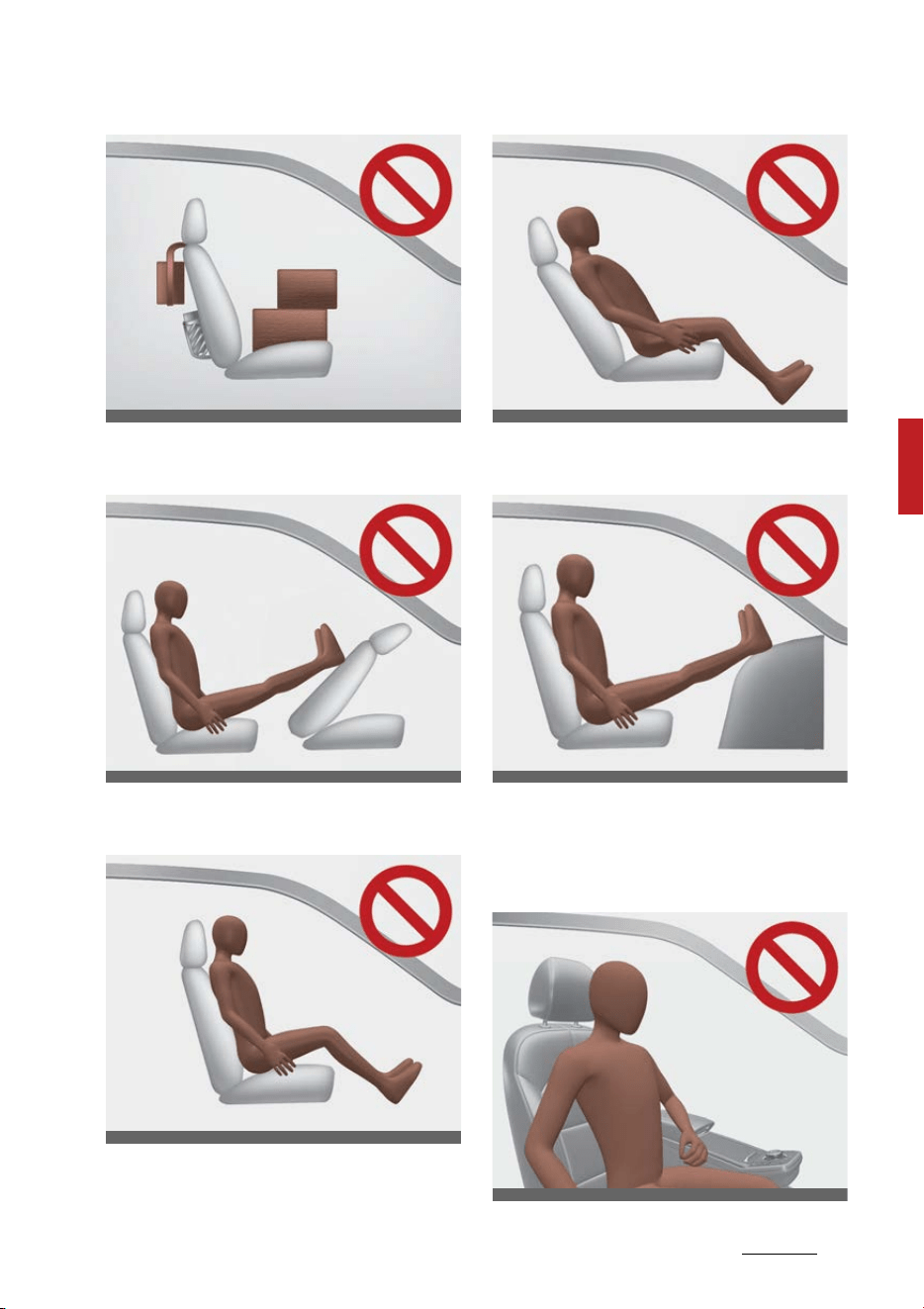
57
4
4
Safety features of your vehicle Air bag - Advanced Supplemental Restraint
System
䳜 Do not place feet on the front
passenger seatback.
䳜 Never sit with hips shifted
towards the front of the seat.
䳜 Never excessively recline the
front passenger seatback.
䳜 Never place feet on the dash
-
board.
䳜 Never lean on the door or center
console.
䳜 Never sit on one side of the front
passenger seat.
ODEEV058055NR
ODEEV058056NR
ODEEV058057NR
ODEEV058002NR
ODEEV058059NR
ODEEV058060NR
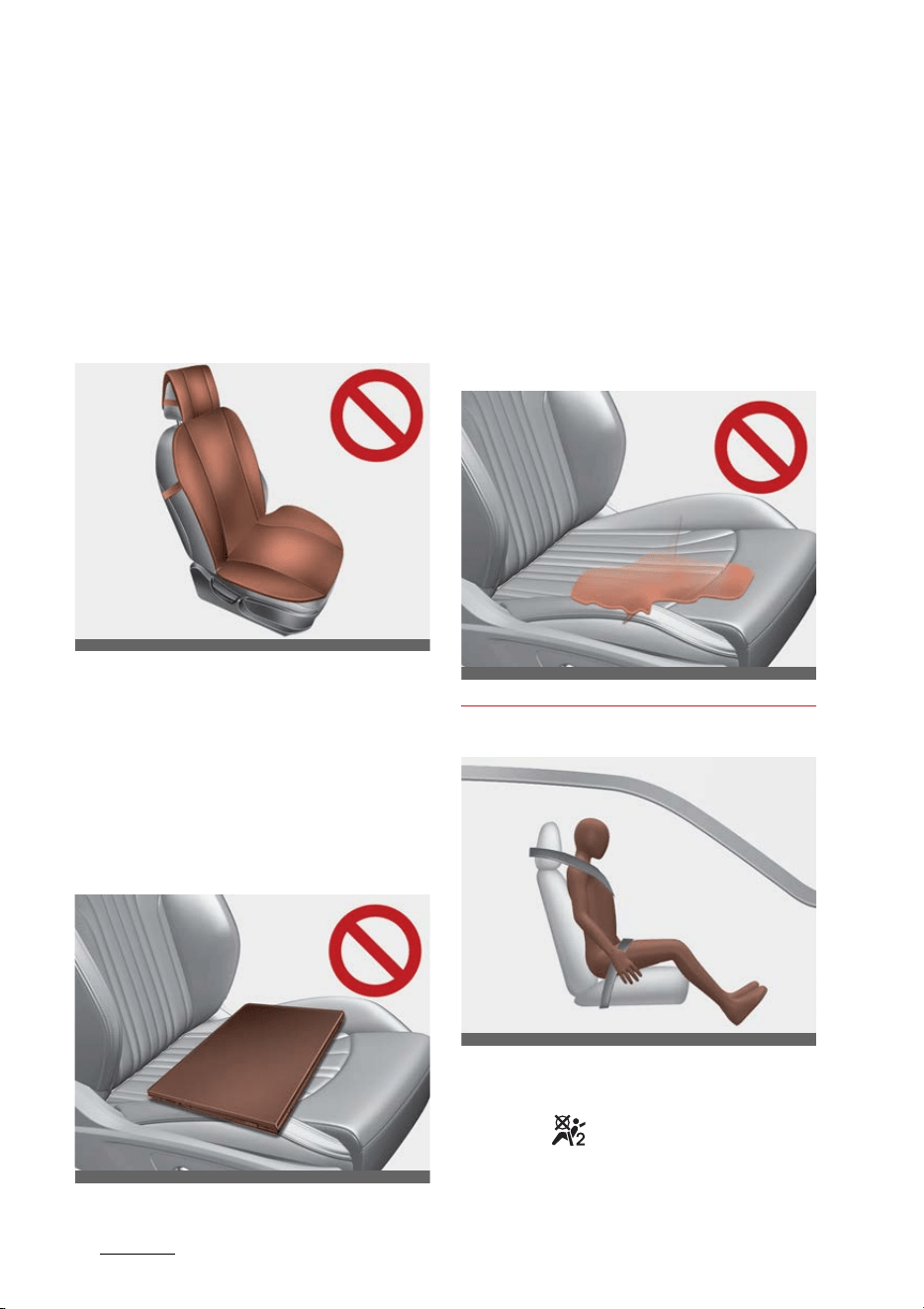
Safety features of your vehicle
584
Air bag - Advanced Supplemental Restraint
System
䳜 Do not use car seat accessories
such as thick blankets and cush
-
ions which cover up the car seat
surface.
䳜 Do not sit on the passenger seat
wearing heavily padded clothes
such as ski wear and hip protec
-
tor.
䳜 Do not place electronic devices
such as laptops, DVD player, or
conductive materials such as
water bottles on the passenger
seat.
䳜 Do not use electronic devices such
as laptops and satellite radios
which use inverter chargers.
䳜 Wet passenger seat:
Do not spill liquid in the passenger
seat. Spilled liquid on the passen
-
ger seat may cause the air bag
warning light to illuminate or mal
-
function. If any liquid is spilled,
make sure the seat has been
completely dried before driving
the vehicle.
Proper position
When an adult is seated in the front
passenger seat, if the PASSENGER
AIR BAG ( ) indicator is on, change
the ENGINE START/STOP button to
the OFF position and ask the pas
-
ODEEV058061NR
ODL3039048
ODL3039049
ODEEV058064NR
59
4
4
Safety features of your vehicle Air bag - Advanced Supplemental Restraint
System
senger to sit properly (sitting
upright with the seatback in an
upright position, centered on the
seat cushion with their seat belt on,
legs comfortably extended and their
feet on the floor). Restart the vehi
-
cle and have the person remain in
that position. This will allow the sys
-
tem to detect the person and to
enable the passenger air bag.
If the PASSENGER AIR BAG ( )
indicator is still on, ask the passen
-
ger to move to the rear seat.
WARNING
PASSENGER AIR BAG ( ) light
Do not allow an adult passenger to
ride in the front seat when the PAS
-
SENGER AIR BAG ( ) indicator is
illuminated, because the air bag will
not deploy in the event of a crash.
The driver must instruct the pas
-
senger to reposition himself in the
seat. Failure to properly position
yourself may lead to air bag deacti
-
vation resulting in air bag non-
deployment in a collision. If the PAS
-
SENGER AIR BAG ( ) indicator
remains illuminated after the pas
-
senger repositions themselves
properly and the car is restarted, it
is recommended that passenger
move to the rear seat because the
passenger's front air bag will not
deploy.
NOTICE
The PASSENGER AIR BAG ( ) indi
-
cator does not illuminate if the front
passenger seat is occupied, the
occupant detection sensor will then
classify the front passenger after
several more seconds Also, if the
ENGINE START/STOP button is
turned to the ON position when
about 3 minutes have elapsed since
the vehicle is in OFF position.
䳜 Even though your vehicle is
equipped with the Occupant
Detection System, never install a
Child Restraint System in the
front passenger's seat. A deploy
-
ing air bag can forcefully strike a
child resulting in serious injuries or
death.
Any child age 13 and under should
ride in the rear seat. Children too
large for child restraints should use
the available lap/shoulder belts. No
matter what type of crash, children
of all ages are safer when
restrained in the rear seat.
If the ODS is not working properly,
the Supplemental Restraint System
(SRS) air bag warning light on the
instrument panel will illuminate
because the passenger's front air
bag is connected with the ODS. If
there is a malfunction of the ODS
the PASSENGER AIRBAG ( ) indi
-
cator will not illuminate. In this case,
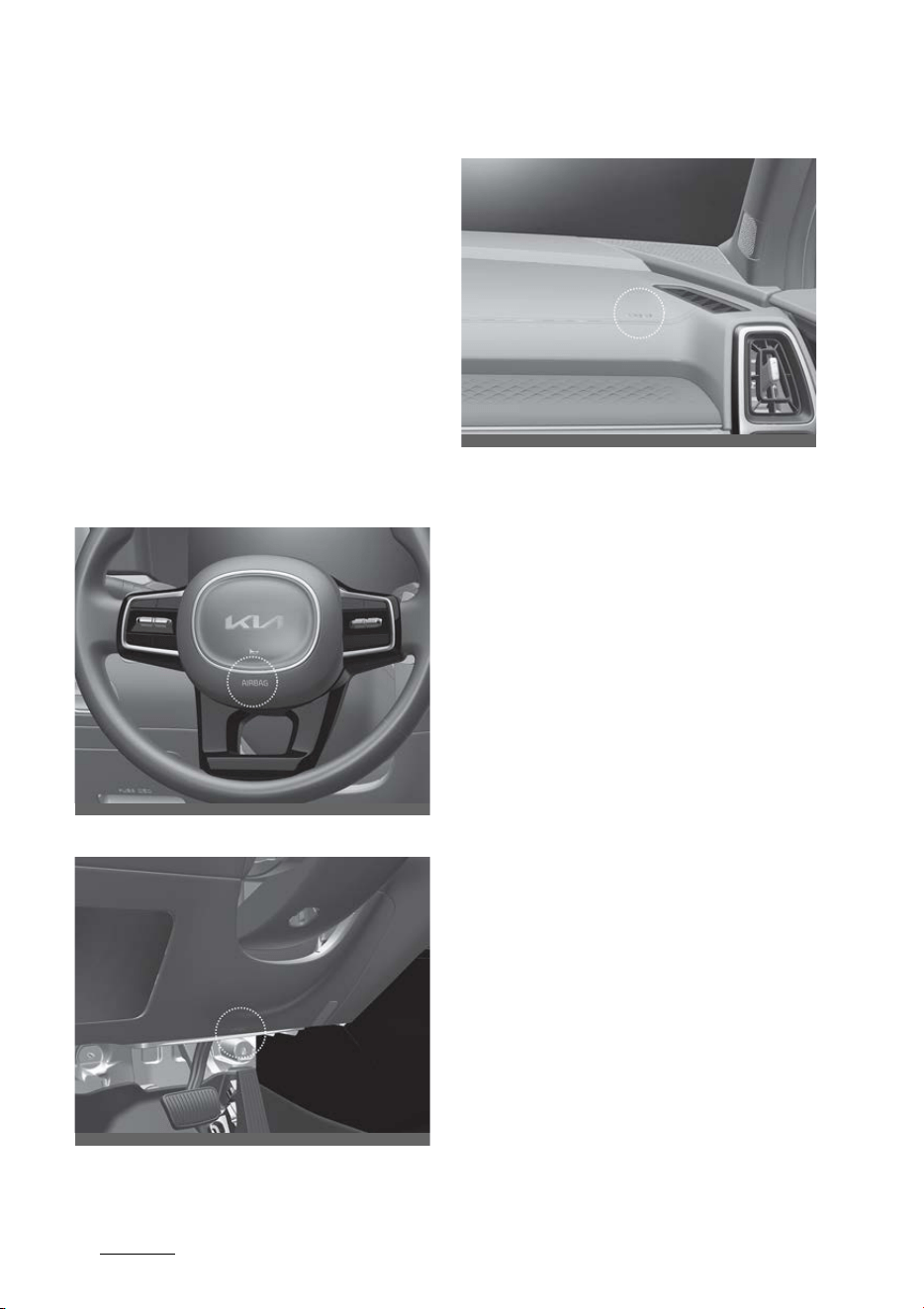
Safety features of your vehicle
604
Air bag - Advanced Supplemental Restraint
System
the passenger's front airbag will
inflate in frontal impact crashes
even if there is no occupant in the
front passenger seat.
Driver's and passenger's front air
bag
Your vehicle is equipped with an
advanced supplemental restraint
(air bag) system and lap/shoulder
belts at both the driver and passen
-
ger seating position.
Driver's front air bag
Driver's knee air bag
Passenger's front air bag
The indication of the system's pres
-
ence are the letters "AIR BAG"
located on the air bag pad cover on
the steering wheel and the passen
-
ger's side front panel pad above the
glove box.
The Supplemental Restraint System
(SRS) consists of air bags installed
under the pad covers in the center
of the steering wheel and the pas
-
senger's side front panel above the
glove box.
OMQ4031045
OMQ4AH030109
OMQ4030046

61
4
4
Safety features of your vehicle Air bag - Advanced Supplemental Restraint
System
The purpose of the SRS is to provide
the vehicle's driver and/or the front
passenger with additional protec
-
tion than that offered by the seat
belt system alone in case of a fron
-
tal impact of sufficient severity. The
SRS uses sensors to gather infor
-
mation about the driver's and front
passenger's seat belt usage and
impact severity.
The seat belt buckle sensor deter
-
mines if the front passenger's seat
belt is fastened.
These sensors provide the ability to
control the SRS deployment based
on whether or not the seat belts are
fastened, and how severe the
impact is.
The advanced SRS offers the ability
to control the air bag inflation with
two levels. A first stage level is pro
-
vided for moderate-severity
impacts. A second stage level is pro
-
vided for more severe impacts.
According to the impact severity
and seat belt usage, the SRS Control
Module (SRSCM) controls the air bag
inflation. Failure to properly wear
seat belts can increase the risk or
severity of injury in an accident.
Additionally, your vehicle is equipped
with an Occupant Detection System
(ODS) in the front passenger's seat.
The ODS detects the presence of a
passenger in the front passenger's
seat and will turn off the front pas
-
senger's air bag under certain condi
-
tions. For more detail, see "Occupant
Detection System (ODS)" on page 4-
53.
WARNING
Modification to the seat structure is
more likely to cause the air bag to
deploy at a different level than
should be provided.
Manufacturers are required by gov
-
ernment regulations to provide a
contact point concerning modifica
-
tions to the vehicle for persons with
disabilities, which modifications may
affect the vehicle's advanced air bag
system. That contact is Kia's tollfree
Customer Assistance center at 1-
800-333-4Kia. However, Kia does
not endorse nor will it support any
changes to any part or structure of
the vehicle that could affect the
advanced air bag system, including
the ODS.

Safety features of your vehicle
624
Air bag - Advanced Supplemental Restraint
System
WARNING
Replacement/modifications
The front passenger seat, dash
-
board or door should not be replaced
except by an authorized Kia dealer
using original Kia parts designed for
this vehicle and model. Any other
such replacement or modification
could adversely affect the operation
of the Occupant Detection System
and your advanced air bags.
Advanced air bags are combined
with pre-tensioner seat belts to
help provide enhanced occupant
protection in frontal crashes. Front
air bags are not intended to deploy
in collisions in which sufficient pro
-
tection can be provided by the seat
belt.
NOTICE
Air bags can only be used once 䳍
have an authorized Kia dealer
replace the air bag immediately
after deployment.
Front air bags are not intended to
deploy in side-impact, rear-impact
or rollover crashes. However, when
frontal deployment threshold is sat
-
isfied at side-impact, front air bags
may deploy. In addition, front air
bags will not deploy in frontal
crashes below the deployment
threshold.
WARNING
SRS wiring
Do not tamper with or disconnect
SRS wiring or other components of
the SRS system. Doing so could
result in injury, due to accidental
deployment of the air bags or by
rendering the SRS inoperative.
WARNING
No attaching objects
No objects (such as crash pad cover,
cellular phone holder, cup holder,
perfume or stickers) should be
placed over or near the air bag mod
-
ules on the steering wheel, instru
-
ment panel, windshield glass, and
the front passenger's panel above
the glove box. Such objects could
cause harm if the vehicle is in a
crash severe enough to cause the
air bags to deploy.
Do not place any objects over the air
bag or between the air bag and
yourself.
Additionally, never place or insert
any object into any small opening
near side airbag labels attached to
the vehicle seats.
When the air bag deploys, the object
may affect the deployment and
result in unexpected accident or
bodily harm.
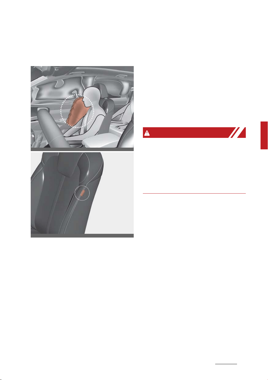
63
4
4
Safety features of your vehicle Air bag - Advanced Supplemental Restraint
System
Side air bag
Your vehicle is equipped with a side
air bag in each front seat.
* The actual air bags in the vehicle
may differ from the illustration.
The purpose of the air bag is to pro
-
vide the vehicle's driver and/or the
front passenger with additional pro
-
tection than that offered by the
seat belt alone.
䳜 The side air bags are designed to
deploy during certain side-impact
collisions, depending on the crash
severity of impact.
䳜 The side air bags may deploy on
the side of the impact or on both
sides.
䳜 The side and/or curtain air bags
on both sides of the vehicle will
deploy if a rollover or possible
rollover is detected.
䳜 The side air bags are not designed
to deploy in all side impact or roll
-
over situations.
WARNING
Unexpected deployment
Avoid impact to the side impact air
-
bag sensor when the ENGINE
START/STOP button is ON to pre
-
vent unexpected deployment of the
side air bag.
䳜 The side air bag is supplemental
to the driver's and the passen
-
ger's seat belt systems and is not
a substitute for them. Therefore
your seat belts must be worn at
all times while the vehicle is in
operation.
䳜 For best protection from the side
air bag system and to avoid being
injured by the deploying side air
bag, both front seat occupants
should sit in an upright position
with the seat belt properly fas
-
tened. The driver's hands should
be placed on the steering wheel at
the 9:00 and 3:00 positions. The
passenger's arms and hands
should be placed on their laps.
OMQ4AH030074
OMQ4AH030049
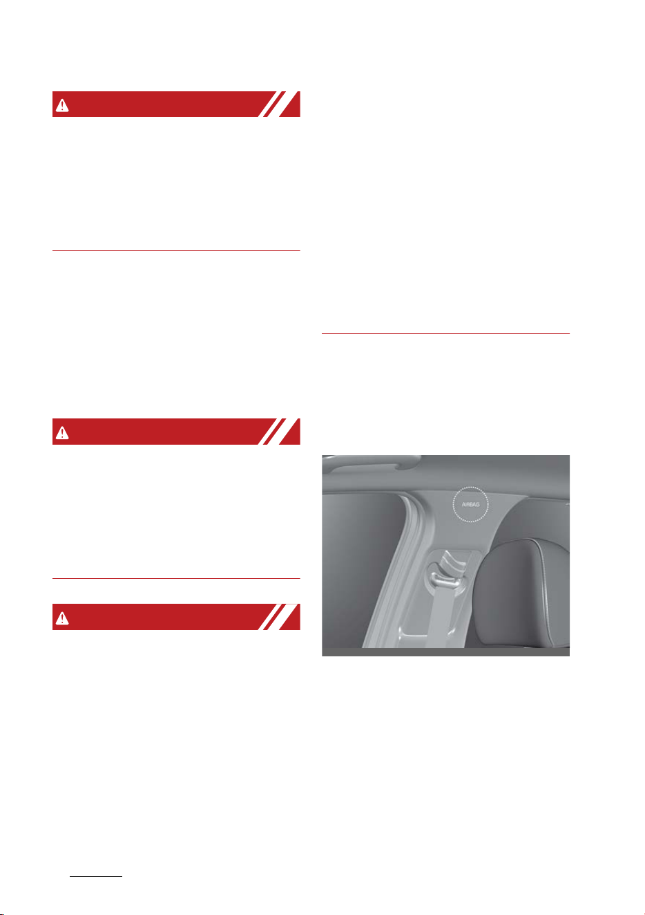
Safety features of your vehicle
644
Air bag - Advanced Supplemental Restraint
System
WARNING
Deployment
Do not install any accessories
including seat covers, on the side or
near the side air bag as this may
affect the deployment of the side
air bags.
䳜 If the seat or seat cover is dam
-
aged, have the vehicle checked
and repaired by an authorized Kia
dealer. Inform the dealer that
your vehicle is equipped with side
air bags and an Occupant Detec
-
tion System (ODS).
WARNING
Flying objects
Do not place any objects (an
umbrella, bag, etc.) between the
front door and the front seat. Such
objects may become dangerous
projectiles if the side airbag inflates.
WARNING
No attaching objects
䳜 Do not place any objects over the
air bag or between the air bag and
yourself. Also, do not attach any
objects around the area the air
bag inflates such as the door, side
door glass, front and rear pillar.
䳜 Do not put any objects between
the side airbag label and seat
cushion. It could cause harm if the
vehicle is in a crash severe enough
to cause the air bags to deploy.
䳜 Never place or insert any object
into any small opening near side
airbag labels attached to the vehi
-
cle seats. When the air bag
deploys, the object may affect
the deployment and result in
unexpected accident or bodily
harm.
䳜 Do not install any accessories on
the side or near the side air bags.
Curtain air bag
Curtain air bags are located along
both sides of the roof rails above
the front and rear doors.
OMQ4030077
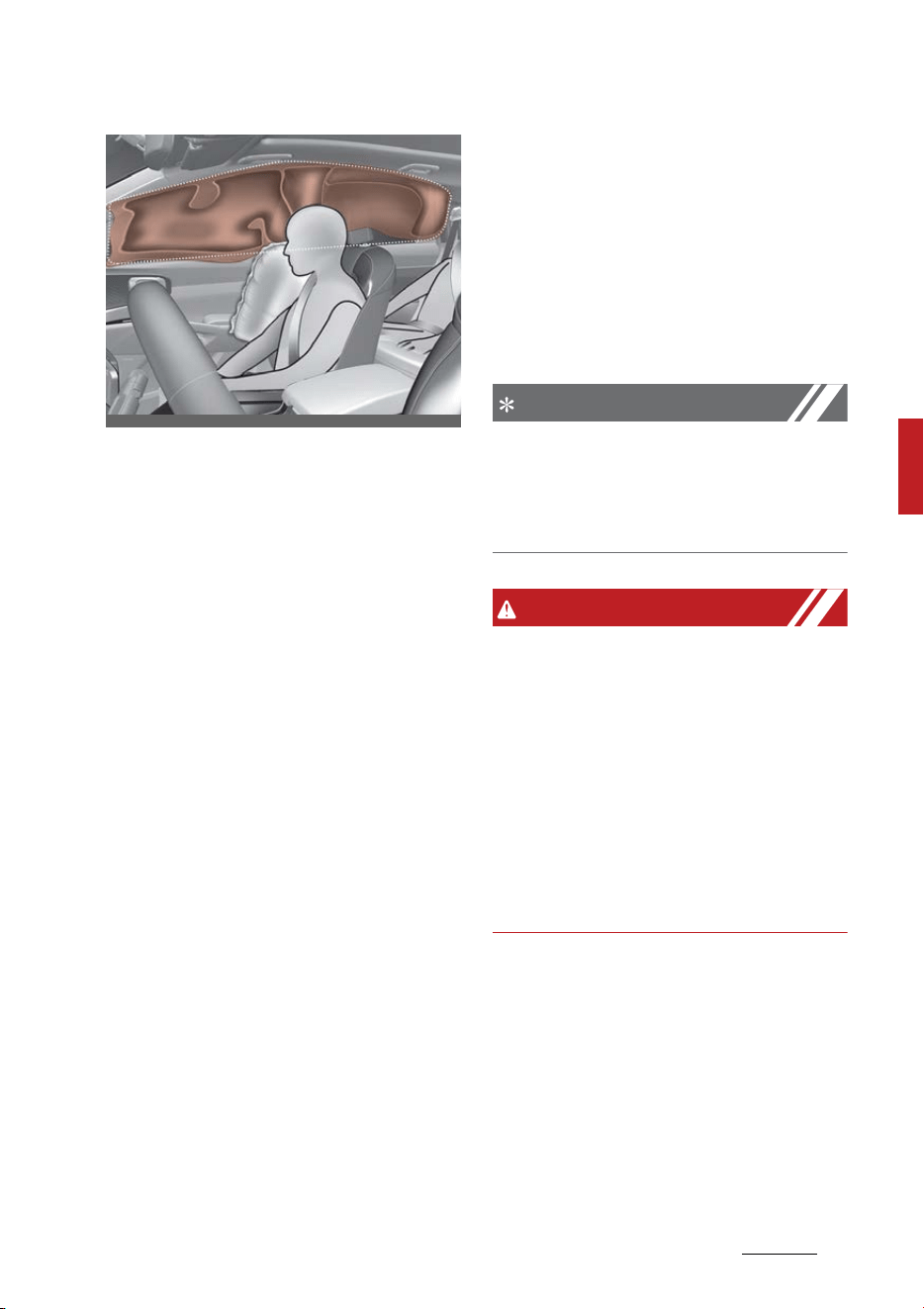
65
4
4
Safety features of your vehicle Air bag - Advanced Supplemental Restraint
System
* The actual air bags in the vehicle
may differ from the illustration.
They are designed to help protect
occupants in certain side impacts
and to help prevent them from
ejecting out of the vehicle as a result
of a rollover, especially when the
seat belts are also in use.
䳜 The curtain air bags are designed
to deploy during certain side
impact collisions, depending on
the severity of impact. However,
when side deployment threshold
is satisfied at front-impact, side
air bags may deploy.
䳜 The curtain air bags may deploy
on the side of the impact or on
both sides.
䳜 Also, the curtain air bags on both
sides of the vehicle will deploy in
certain rollover situations.
䳜 The curtain air bags are not
designed to deploy in all side
impact or rollover situations.
Do not allow the passengers to lean
their heads or bodies against the
doors, put their arms on the doors,
stretch their arms out of the win
-
dow or place objects between the
doors and passengers when they
are seated on seats equipped with
side impact and/or curtain air bags.
NOTICE
Never try to open or repair any
components of the side and curtain
air bag system. This should only be
done by an authorized Kia dealer.
WARNING
No attaching objects
䳜 Do not place any objects over the
air bag. Also, do not attach any
objects around the area the air
bag inflates such as the door, side
door glass, front and rear pillar,
roof side rail.
䳜 Do not hang hard, breakable, or
heavy objects on the coat hooks
for safety reasons.
OMQ4AH030076
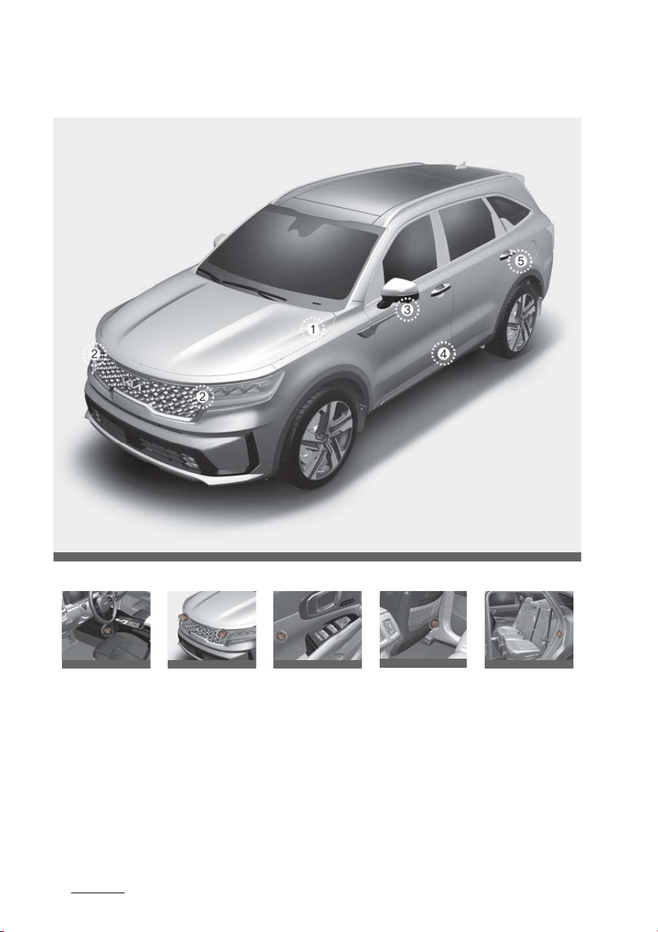
Safety features of your vehicle
664
Air bag - Advanced Supplemental Restraint
System
Air bag collision sensors
* The actual shape and position of sensors may differ from the illustration.
1. Supplemental Restraint System (SRS) control module/rollover sensor
2. Front impact sensor
3. Side pressure sensors (front door)
4. Side impact sensor (B-pillar)
5. Side impact sensor (C-pillar)
OMQ4H031002
1 2 3 4 5
OMQ4AH031051
OMQ4031052
OMQ4030053
OMQ4030080
OMQ4A031054MX
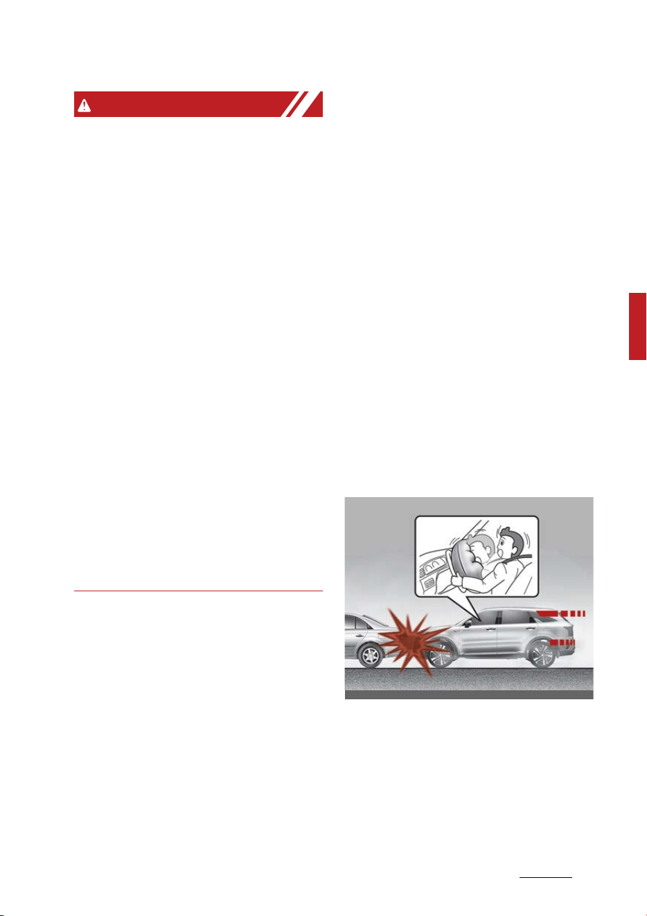
67
4
4
Safety features of your vehicle Air bag - Advanced Supplemental Restraint
System
WARNING
Air bag sensors
䳜 Do not hit or allow any objects to
impact the locations where air
bags or sensors are installed.
This may cause unexpected air
bag deployment, which could
result in serious personal injury or
death.
䳜 If the installation location or angle
of the sensors is altered in any
way, the air bags may deploy
when they should not or they
may not deploy when they
should.
Therefore, do not try to perform
maintenance on or around the air
bag sensors. Have the vehicle
checked and repaired by an
authorized Kia dealer.
䳜 Do not arbitrarily touch the front
impact sensor. When the angle of
the sensor is changed, the air bag
system may malfunction.
Problems may arise if the sensor
installation angles are changed due
to the deformation of the front
bumper, front end module, body or
front doors where side collision sen
-
sors are installed. Have the vehicle
checked and repaired by an autho
-
rized Kia dealer.
Installing bumper guards (or side
step or running board) or replacing a
bumper (or front door module) with
non-genuine parts may adversely
affect your vehicle's collision and air
bag deployment performance.
Why didn't my air bag go off in a
collision? (Inflation and non-infla
-
tion conditions of the air bag)
There are many types of accidents
in which the air bag would not be
expected to provide additional pro
-
tection.
These include rear impacts, second
or third collisions in multiple impact
accidents, as well as low speed
impacts.
Air bag inflation conditions
Front air bags
Front air bags are designed to
inflate in a frontal collision depend
-
ing on several factors, including the
severity of impact of the front colli
-
sion.
OMQ4H030003
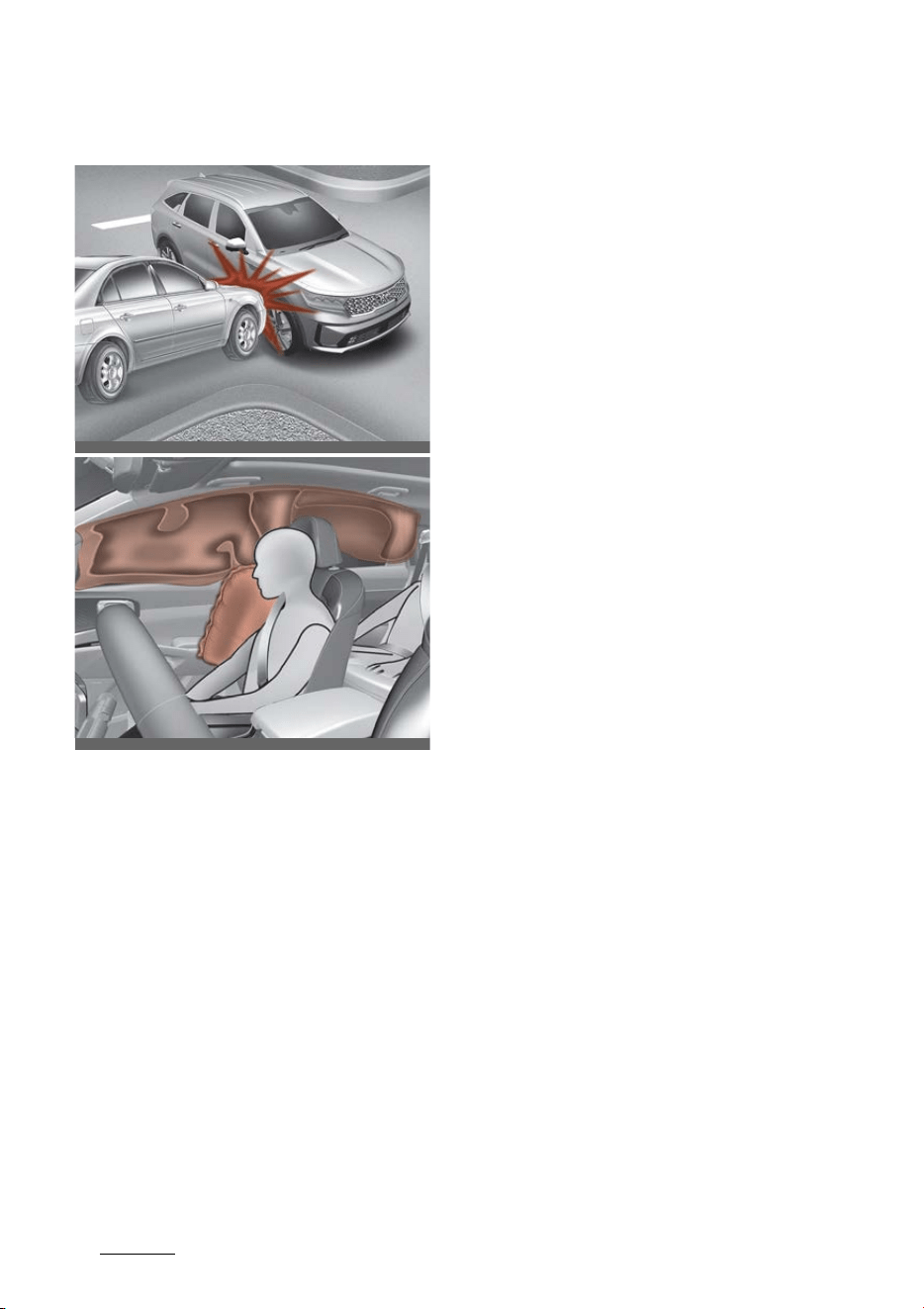
Safety features of your vehicle
684
Air bag - Advanced Supplemental Restraint
System
Side and curtain air bags
* The actual air bags in the vehicle
may differ from the illustration.
Side and/or curtain air bags are
designed to inflate when an impact
is detected by side collision sensors
depending on several factors,
including the severity of impact
resulting from a side impact colli
-
sion.
Also, the side and curtain air bags
are designed to inflate when a roll
-
over is detected by a rollover sensor.
Although the front air bags (driver's
and front passenger's air bags) are
primarily designed to inflate in fron
-
tal collisions, they may inflate in
other types of collisions if the front
impact sensors detect a sufficient
frontal force in another type of
impact.
Similarly, although side and curtain
air bags are designed to inflate in
certain side impact collisions, they
may inflate in other types of colli
-
sions where a side force is detected
by the sensors. For instance, side air
bag and/or curtain air bags may
inflate if rollover sensors indicate
the possibility of a rollover occurring
(even if none actually occurs) or in
other situations, including when the
vehicle is tilted while being towed.
Even if side and/or curtain air bags
do not provide impact protection in
a rollover, they will deploy to pre
-
vent ejection of occupants, espe
-
cially those who are restrained with
seat belts.
If the vehicle chassis is impacted by
bumps or objects on unimproved
roads, the air bags may deploy.
Drive carefully on unimproved roads
or on surfaces not designed for
vehicle traffic to prevent unintended
air bag deployment.
OMQ4PH031004L
OMQ4AH030078
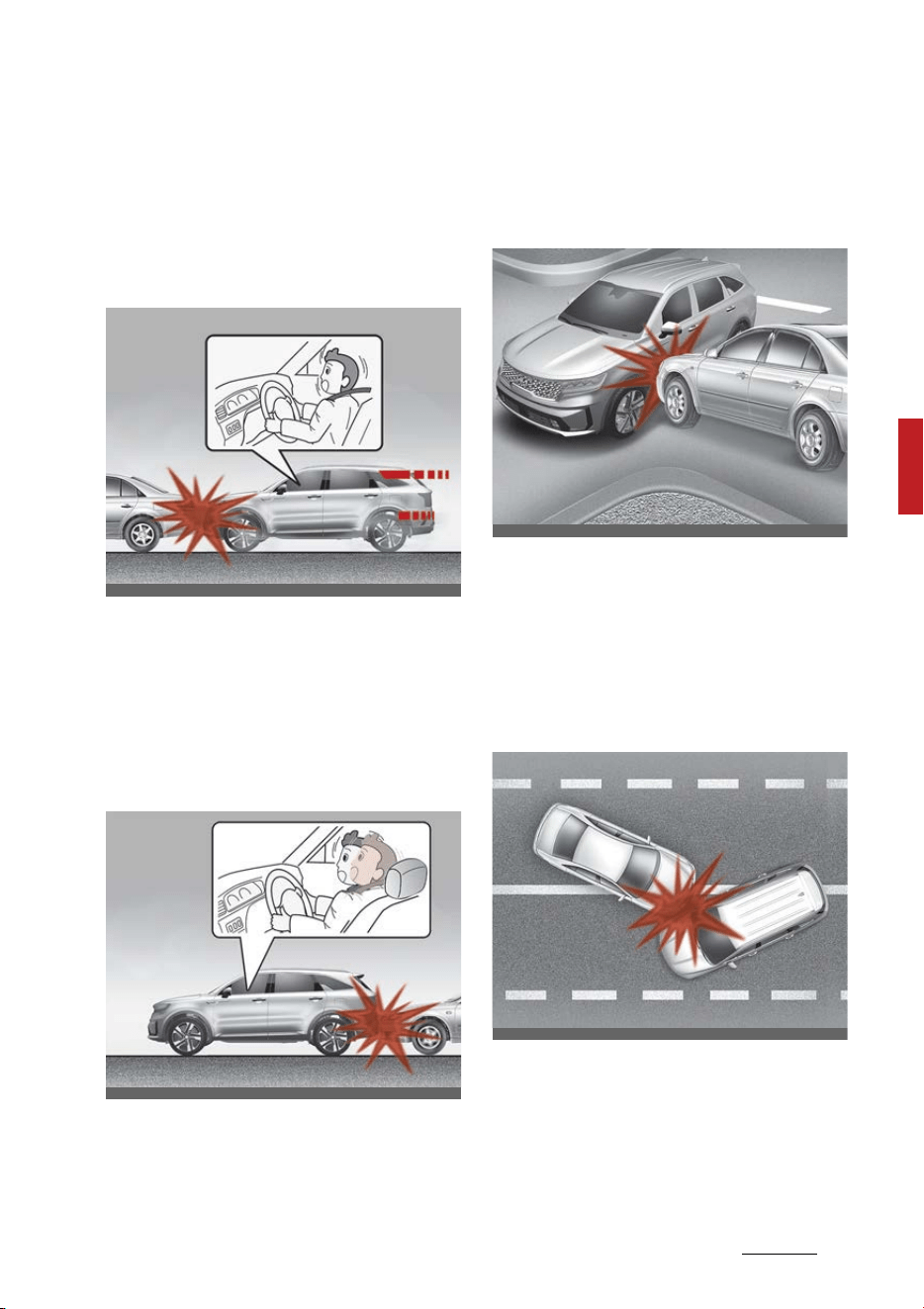
69
4
4
Safety features of your vehicle Air bag - Advanced Supplemental Restraint
System
Air bag non-inflation conditions
䳜 Air bags may not deploy in certain
low-speed collisions where the air
bag would not add any benefit
beyond the protection already
offered by the seat belts.
䳜 Front air bags are not designed to
inflate in rear collisions, because
occupants are moved backward
by the force of the impact. In this
case, inflated air bags would not
be able to provide any additional
benefit.
䳜 Front airbags may not inflate in
side impact collisions, because
passengers move in the direction
of the collision. Thus, in side
impacts, frontal airbag deploy
-
ment would not provide additional
occupant protection.
䳜 In an angled collision, the force of
impact may direct the occupants
in a direction where the air bags
would not be able to provide any
additional benefit, and thus the
sensors may not deploy any air
bags.
䳜
䳜 Just before impact, drivers often
brake heavily. Such heavy braking
lowers the front portion of the
vehicle causing it to "ride" under a
vehicle with a higher ground
OMQ4H030005
OMQ4H030006
OMQ4H031007
OMQ4030060
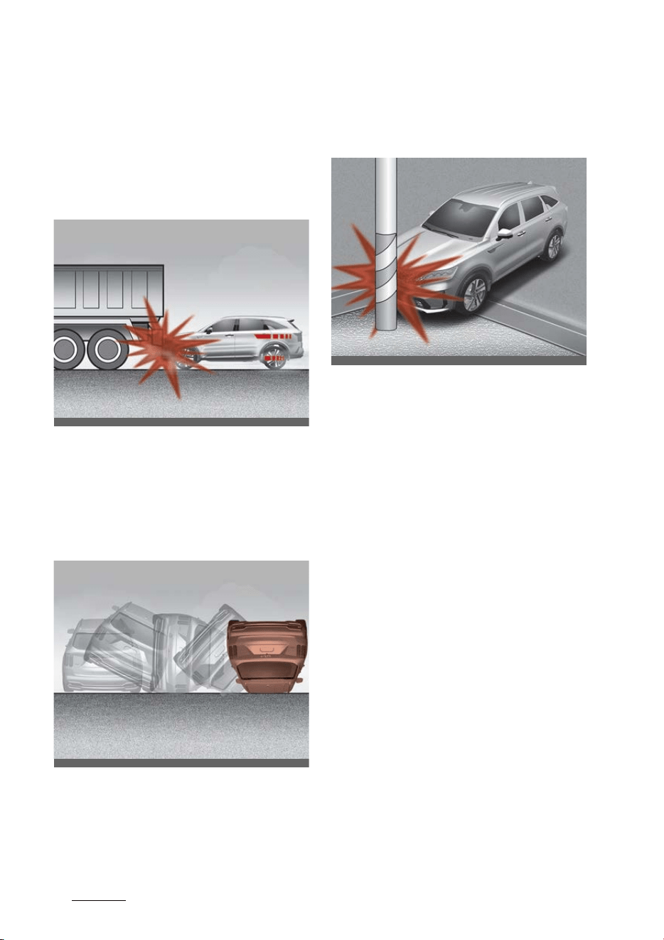
Safety features of your vehicle
704
Air bag - Advanced Supplemental Restraint
System
clearance. Air bags may not
inflate in this "under-ride" situa
-
tion because deceleration forces
that are detected by sensors may
be significantly reduced by such
"under-ride" collisions.
䳜 Front air bags may not inflate in
all rollover accidents when the
SRS Control Module (SRSCM) indi
-
cates that the front air bag
deployment would not provide
additional occupant protection.
䳜 Airbags may not inflate if the
vehicle collides with an object such
as a utility pole or tree. This is
because the point of impact is
concentrated in one area and the
full force of the impact is not
delivered to the sensors.
Supplemental Restraint System
(SRS) care
The Supplemental Restraint System
(SRS) is virtually maintenance-free
and so there are no parts you can
safely service by yourself.
If the SRS air bag warning light does
not illuminate, or continuously
remains on, have your vehicle
immediately inspected by an autho
-
rized Kia dealer.
Any work on the SRS, such as
removing, installing, repairing, or
any work on the steering wheel, the
front passenger's panel, front seats
and roof rails must be performed by
an authorized Kia dealer. Improper
handling of the SRS may result in
serious personal injury.
OMQ4H030008
OMQ4031061
OMQ4H031009

71
4
4
Safety features of your vehicle Air bag - Advanced Supplemental Restraint
System
For cleaning the air bag pad covers,
use only a soft, dry cloth or one
which has been moistened with
plain water. Solvents or cleaners
could adversely affect the air bag
covers and proper deployment of
the system.
If components of the air bag system
must be discarded, or if the vehicle
must be scrapped, certain safety
precautions must be observed. An
authorized Kia dealer knows these
precautions and can give you the
necessary information. Failure to
follow these precautions and proce
-
dures could increase the risk of
bodily injury.
WARNING
Tampering with SRS
Do not tamper with or disconnect
SRS wiring or other components of
the SRS system. Doing so could
result in the accidental inflation of
the air bag or render the SRS inop
-
erative.
WARNING
Towing vehicle
Always have the vehicle off and wait
for 3 minutes when your vehicle is
being towed. The side air bags may
inflate if the vehicle is tilted such as
when being towed because of the
rollover sensors in the vehicle.
Additional safety precautions
䳜 Never let passengers ride in the
cargo area or on top of a folded-
down back seat. All occupants
should sit upright, fully back in
their seats with their seat belts
on and their feet on the floor.
䳜 Passengers should not move out
of or change seats while the vehi
-
cle is moving. A passenger who is
not wearing a seat belt during a
crash or emergency stop can be
thrown against the inside of the
vehicle, against other occupants,
or out of the vehicle.
䳜 Each seat belt is designed to
restrain one occupant. If more
than one person uses the same
seat belt, they could be seriously
injured or killed in a collision.
䳜 Do not use any accessories on
seat belts. Devices claiming to
improve occupant comfort or
reposition the seat belt can
reduce the protection provided by
the seat belt and increase the
chance of serious injury in a crash.
䳜 Passengers should not place hard
or sharp objects between them
-
selves and the air bags. Carrying
hard or sharp objects on your lap
or in your mouth can result in
injuries if an air bag inflates.

Safety features of your vehicle
724
Air bag - Advanced Supplemental Restraint
System
䳜 Keep occupants away from the
air bag covers. All occupants
should sit upright, fully back in
their seats with their seat belts
on and their feet on the floor. If
occupants are too close to the air
bag covers, they could be injured
if the air bags inflate.
䳜 Do not attach or place objects on
or near the air bag covers. Any
object attached to or placed on
the front or side air bag covers
could interfere with the proper
operation of the air bags.
䳜 Do not modify the front
seats.Modification of the front
seats could interfere with the
operation of the supplemental
restraint system sensing compo
-
nents or side air bags.
䳜 Do not place items under the
front seats. Placing items under
the front seats could interfere
with the operation of the supple
-
mental restraint system sensing
components and wiring har
-
nesses.
䳜 Never hold an infant or child on
your lap. The infant or child could
be seriously injured or killed in the
event of a crash. All infants and
children should be properly
restrained in appropriate child
safety seats or seat belts in the
rear seat.
WARNING
䳜 Sitting improperly or out of posi
-
tion can cause occupants to be
shifted too close to a deploying air
bag, strike the interior structure
or be thrown from the vehicle
resulting in serious injury or
death.
䳜 Always sit upright with the seat
-
back in an upright position, cen
-
tered on the seat cushion with
your seat belt on, legs comfort
-
ably extended and your feet on
the floor.
Adding equipment to or modifying
your air bag-equipped vehicle
If you modify your vehicle by chang
-
ing your vehicle's frame, bumper
system, front end or side sheet
metal or ride height, this may affect
the operation of your vehicle's air
bag system.
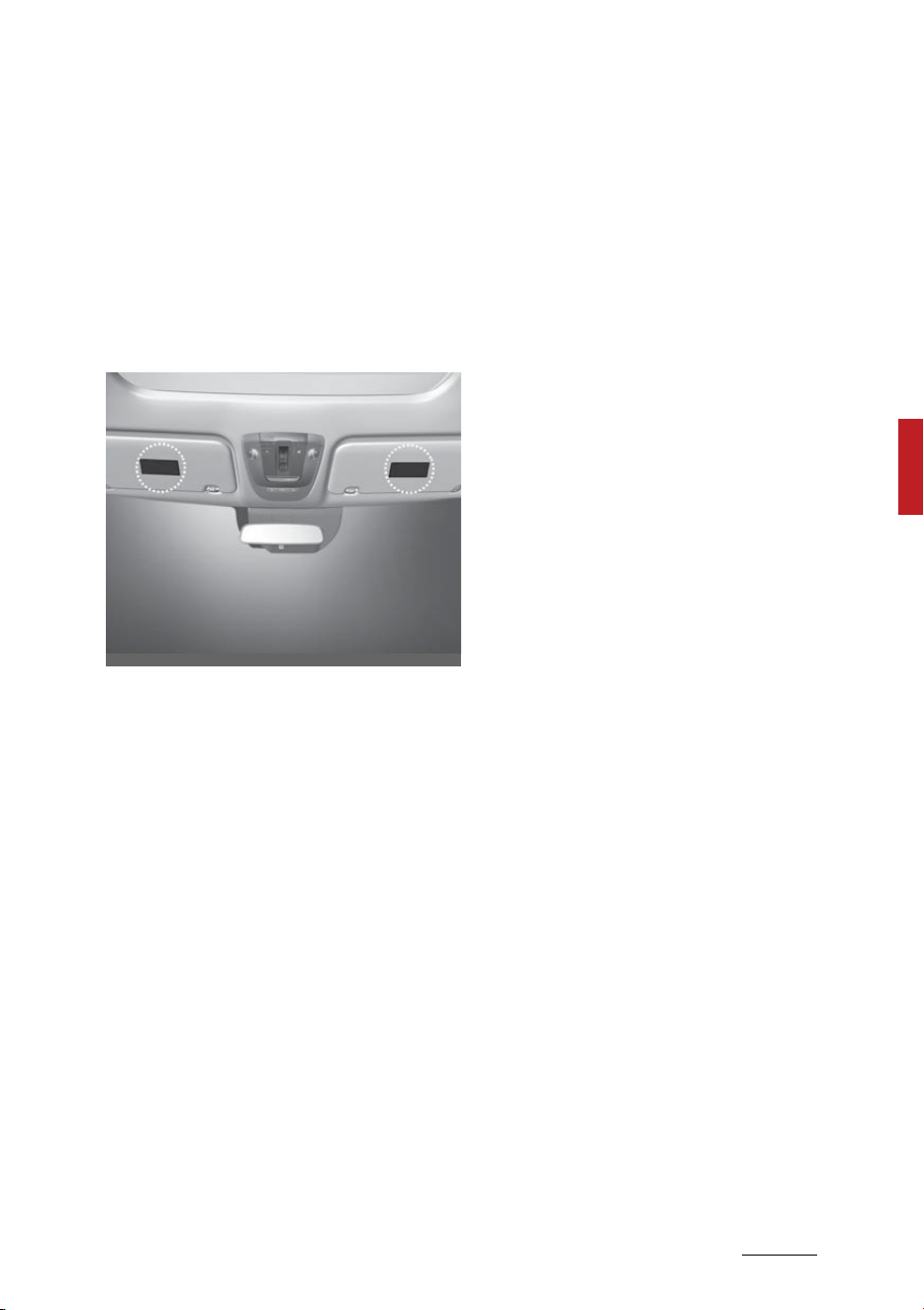
73
4
4
Safety features of your vehicle Air bag - Advanced Supplemental Restraint
System
Air bag warning labels
Air bag warning labels, some
required by the U.S. National High
-
way Traffic Safety Administration
(NHTSA), are attached to the sun
visor to alert the driver and passen
-
gers of potential risks of the air bag
system.
OMQ4AH030100


5Features of your vehicle
Features of your vehicle
Keys ............................................................................................ 5-7
䳜 Smart key ................................................................................ 5-7
䳜 Battery replacement ........................................................... 5-11
Immobilizer system................................................................5-13
䳜 Smart key immobilizer system..........................................5-13
Theft-alarm system ..............................................................5-14
䳜 Armed stage..........................................................................5-14
䳜 Theft-alarm stage ...............................................................5-15
䳜 Disarmed stage.....................................................................5-15
Door locks.................................................................................5-17
䳜 With the smart key..............................................................5-17
䳜 With the mechanical key.....................................................5-18
䳜 Operating door locks from inside the vehicle ..................5-19
䳜 Door lock/unlock features...................................................5-21
䳜 Child-protector rear door lock ...........................................5-22
䳜 Electronic child safety lock system...................................5-22
䳜 In case of an emergency .....................................................5-23
䳜 Rear Occupant Alert (ROA) System ..................................5-24
Driver Position Memory System..........................................5-26
䳜 Storing memory positions ..................................................5-27
䳜 Recalling memory positions ...............................................5-27
䳜 Driver position memory system reset .............................5-27
䳜 Easy access function ...........................................................5-28
Liftgate.....................................................................................5-29
䳜 Opening the liftgate.............................................................5-29
䳜 Closing the liftgate...............................................................5-30
䳜 Emergency liftgate safety release....................................5-30
Power liftgate .........................................................................5-32

5 Features of your vehicle
䳜 Opening the liftgate .............................................................5-33
䳜 Closing the liftgate ...............................................................5-34
䳜 Power liftgate non-opening conditions............................5-35
䳜 How to reset the power liftgate........................................5-36
䳜 Power liftgate speed adjustment......................................5-36
䳜 Power tailgate opening height...........................................5-37
Smart Liftgate with Auto Open............................................5-38
䳜 How to use the Smart Liftgate with Auto Open.............5-38
䳜 How to deactivate the Smart Liftgate with Auto Open func
-
tion using the smart key .....................................................5-39
䳜 Detecting area.......................................................................5-40
Windows ...................................................................................5-42
䳜 Window opening and closing...............................................5-43
䳜 Power window lock button .................................................5-45
Hood ..........................................................................................5-47
䳜 Opening the hood .................................................................5-47
䳜 Hood open warning ..............................................................5-47
䳜 Closing the hood ...................................................................5-47
Fuel filler door .........................................................................5-48
䳜 Opening the fuel filler door (hybrid vehicle).....................5-48
䳜 Opening the fuel filler door (Plug-in hybrid vehicle).......5-49
䳜 Closing the fuel filler door...................................................5-51
Panoramic sunroof .................................................................5-55
䳜 Power sunshade ...................................................................5-56
䳜 Tilt open/close.......................................................................5-56
䳜 Slide open/close ....................................................................5-57
䳜 Automatic reversal...............................................................5-57
䳜 Resetting the sunroof .........................................................5-58
䳜 Sunroof open warning .........................................................5-59

5Features of your vehicle
Steering wheel ........................................................................5-60
䳜 Electric power steering (EPS).............................................5-60
䳜 Tilt & telescopic steering wheel ......................................... 5-61
䳜 Heated steering wheel ........................................................5-62
䳜 Horn ........................................................................................5-63
Mirrors ......................................................................................5-64
䳜 Inside rear view mirror ........................................................5-64
䳜 Outside rear view mirror.....................................................5-76
Instrument cluster..................................................................5-80
䳜 Full LCD cluster .....................................................................5-81
䳜 Adjusting instrument cluster illumination........................5-82
䳜 Gauges....................................................................................5-83
䳜 Transmission shift indicator...............................................5-88
LCD display...............................................................................5-90
䳜 LCD display modes ...............................................................5-91
LCD displays...........................................................................5-100
䳜 Trip information (trip computer).....................................5-100
䳜 Service mode.......................................................................5-103
䳜 LCD display messages .......................................................5-104
Warning and indicator lights...............................................5-111
䳜 Warning lights .....................................................................5-111
䳜 Indicator lights ....................................................................5-118
Head-Up Display (HUD)........................................................5-122
䳜 Head-Up Display Information...........................................5-123
䳜 Head-Up Display Setting...................................................5-123
Rear View Monitor (RVM)....................................................5-124
䳜 Rear View Monitor Settings .............................................5-125
䳜 Rear View Monitor Operation...........................................5-125

5 Features of your vehicle
䳜 Rear View Monitor Malfunction and Limitations ......... 5-126
Surround View Monitor (SVM) ........................................... 5-126
䳜 Surround View Monitor Settings .................................... 5-128
䳜 Surround View Monitor Operation.................................. 5-128
䳜 Surround View Monitor Malfunction and Limitations . 5-129
Reverse Parking Distance Warning (PDW)....................... 5-130
䳜 Reverse Parking Distance Warning Settings................. 5-130
䳜 Reverse Parking Distance Warning Operation.............. 5-131
䳜 Reverse Parking Distance Warning................................. 5-131
䳜 Reverse Parking Distance Warning Malfunction and Precau
-
tions ..................................................................................... 5-132
Forward/Reverse Parking Distance Warning (PDW)...... 5-134
䳜 Detecting sensor ............................................................... 5-134
䳜 Forward/Reverse Parking Distance Warning Settings 5-134
䳜 Forward/Reverse Parking Distance Warning
Operation ............................................................................ 5-135
䳜 Forward/Reverse Parking Distance Warning
Malfunction and Precautions ........................................... 5-138
Lighting.................................................................................. 5-140
䳜 Battery saver function ..................................................... 5-140
䳜 Headlamp delay function ................................................. 5-140
䳜 Daytime Running Light (DRL) .......................................... 5-141
䳜 Lighting control.................................................................. 5-141
䳜 Operating high beam ....................................................... 5-142
䳜 Operating turn signals and lane change signals........... 5-143
䳜 Operating front fog light ................................................. 5-144
䳜 High Beam Assist (HBA) ................................................... 5-144
Wipers and washers ............................................................ 5-147
䳜 Auto control........................................................................ 5-148

5Features of your vehicle
䳜 Operating windshield washers.........................................5-149
䳜 Operating rear window wiper and washer switch........5-150
Welcome system ..................................................................5-151
Interior lights .........................................................................5-152
䳜 Automatic turn off function.............................................5-152
䳜 Map lamp .............................................................................5-153
䳜 Room lamp ..........................................................................5-154
䳜 Luggage room lamp ...........................................................5-154
䳜 Vanity mirror lamp.............................................................5-155
䳜 Glove box lamp....................................................................5-155
Climate control system .......................................................5-156
䳜 System operation...............................................................5-156
䳜 Climate control air filter ....................................................5-158
䳜 Air conditioning refrigerant label.....................................5-159
䳜 Checking the amount of air conditioner refrigerant
and compressor lubricant .................................................5-159
Automatic climate control system ....................................5-161
䳜 Heating and air conditioning automatically ...................5-163
䳜 Heating and air conditioning manually ...........................5-165
Windshield defrosting and defogging ...............................5-172
䳜 Defogging inside windshield .............................................5-172
䳜 Defrosting outside windshield..........................................5-173
䳜 Auto defogging system.....................................................5-173
䳜 Defroster .............................................................................5-174
䳜 Defogging logic ...................................................................5-175
Storage compartment .........................................................5-176
䳜 Center console storage .....................................................5-176
䳜 Glove box..............................................................................5-176
Interior features ...................................................................5-177

5 Features of your vehicle
䳜 Ambient light...................................................................... 5-177
䳜 Cup holder........................................................................... 5-178
䳜 Seat warmer....................................................................... 5-179
䳜 Air ventilation seat ............................................................ 5-181
䳜 Sun visor.............................................................................. 5-182
䳜 USB charger........................................................................ 5-183
䳜 Power outlet....................................................................... 5-184
䳜 AC Inverter.......................................................................... 5-185
䳜 Wireless smart phone charging system........................ 5-187
䳜 Coat hook ............................................................................ 5-190
䳜 Side curtain......................................................................... 5-191
䳜 Floor mat anchors ............................................................. 5-192
䳜 Luggage net holder ........................................................... 5-192
䳜 Cargo security screen ....................................................... 5-193
䳜 Luggage board ................................................................... 5-194
䳜 Luggage tray ...................................................................... 5-195
䳜 Luggage side tray.............................................................. 5-195
Exterior features ................................................................. 5-196
䳜 Roof rack............................................................................. 5-196
Infotainment system .......................................................... 5-197
䳜 Audio system ..................................................................... 5-197
Declaration of Conformity.................................................. 5-202
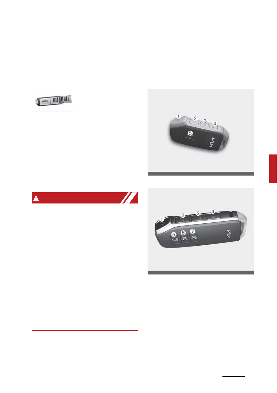
7
5
5
Features of your vehicle Keys
Features of your vehicle
Keys
Record your key number
The key code num
-
ber is stamped on
the key code tag
attached to the key set. Should you
lose your keys, this number will
enable an authorized Kia dealer to
duplicate the keys easily. Remove
the key code tag and store it in a
safe place. Also, record the key code
number and keep it in a safe and
handy place, but not in the vehicle.
WARNING
Never leave the keys in your vehicle
Leaving children unattended in a
vehicle with the keys is dangerous
even if the vehicle is ACC or ON posi
-
tion.
Unattended children could press the
ENGINE START/STOP button and
may operate power windows or
other controls, or even make the
vehicle move, which could result in
serious bodily injury or even death.
Never leave the keys in your vehicle
with unsupervised children, when
the engine is running.
Smart key
With a smart key, you can lock or
unlock a door and even start the
engine without inserting the key.
Type A
Type B
Lock (1)
All doors are locked if the lock but
-
ton is pressed. If all doors are closed,
the hazard warning lights will blink
and the chime will sound once to
indicate that all doors are locked.
Also, if the lock button is pressed
once more within 4 seconds, the
OMQ4041584
OMQ4041578

Features of your vehicle
85
Keys
hazard warning lights will blink and
the chime will sound once to confirm
that the door is locked.
However, if any door remains open,
the hazard warning lights (and/or
the chime) will not operate. But if all
doors are closed after the lock but
-
ton is pressed, the hazard warning
lights will blink once.
Unlock (2)
The driver's door is unlocked if the
unlock button is pressed once. The
hazard warning lights will blink twice
to indicate that the driver's door is
unlocked.
All doors are unlocked if the unlock
button is pressed once more within
4 seconds. The hazard warning
lights will blink and the chime will
sound twice again to indicate that all
doors are unlocked. After pressing
this button, the doors will lock auto
-
matically unless you open any door
within 30 seconds.
If you attempt to lock or unlock the
door by pressing the door lock/
unlock button in any of the following
states, the door will not be locked or
unlocked.
䳜 When you want to lock or unlock
the door in the ACC or ON state.
䳜 When you want to lock a door in a
car with one or more doors open.
Depending on the vehicle, the driver
can turn off or set the 2-press
unlock setting function.
NOTICE
If the smart key is inoperative due
to exposure to water or liquids, it
will not be covered by your manu
-
facturer's vehicle warranty.
Liftgate unlock/open (3)
The liftgate is unlocked or opened (if
equipped) if the button is pressed
for more than 1 second.
Panic alarm (4)
The horn sounds and the hazard
warning lights blink for about 30
seconds if this button is pressed for
more than 0.5 seconds. To stop the
horn and lights, press any button on
the transmitter.
Remote start (5) (if equipped)
You can start the vehicle using the
remote start button (5) of the
smart key.
To start the vehicle remotely:
䳜 Lock the doors by pressing the
door lock button (1) within 32 ft
(10 m) distance from the vehicle.
䳜 Press the remote start button for
over 2 seconds within 4 seconds
after locking the doors.
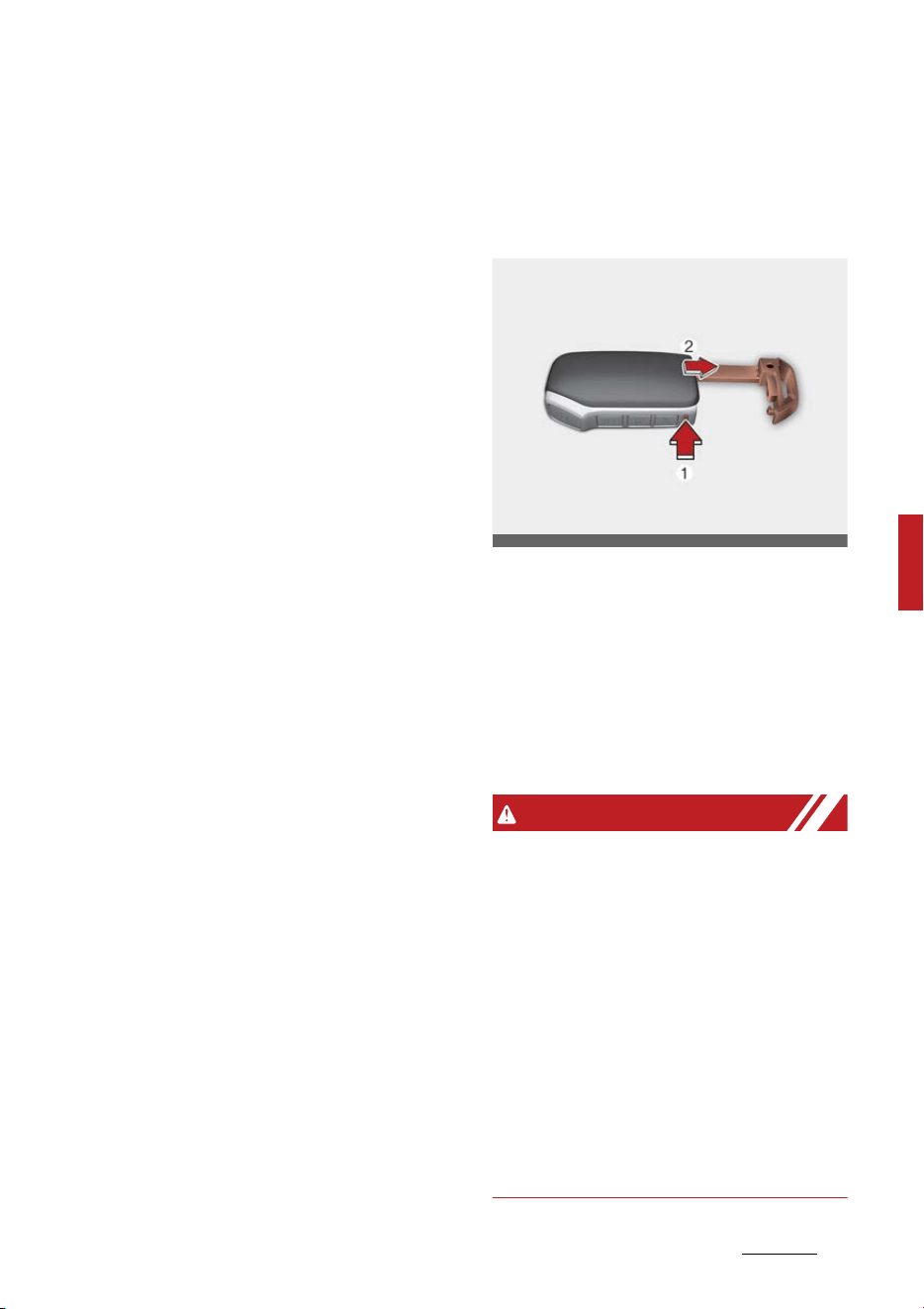
9
5
5
Features of your vehicle Keys
Press the remote start button once
to turn off the vehicle.
If no further action for operating/
driving the vehicle is taken, the vehi
-
cle will be turned off 10 minutes
after starting the vehicle remotely.
While remote starting, the hazard
warning lights blink 3 times. If you
want to stop the engine, press the
Remote Start button (5) again.
Remote smart parking assist
(RSPA) (6, 7) (if equipped)
The Remote smart parking assist
(RSPA) helps the drivers park their
vehicle by using sensors to measure
parking spaces and control the
steering wheel, gear shift and vehi
-
cle speed to semi-automatically
park the vehicle. With the smart
key, the driver can move the vehicle
forward or backward using the for
-
ward/backward buttons (6, 7) on
the smart key. For more informa
-
tion, refer to "Remote Smart Park
-
ing Assist (RSPA) (if equipped)" on
page 5-233.
Start-up
You can start the vehicle without
inserting the key.
* For more information, refer to
"ENGINE START/STOP button (if
equipped)" on page 6-9.
Mechanical key
If the smart key does not operate
normally, you can lock or unlock the
door by using the mechanical key.
To remove the mechanical key,
press and hold the release button
(1) and remove the mechanical key
(2).
To reinstall the mechanical key, put
the key into the hole and push it
until a "click" sound is heard.
WARNING
Smart key
Never leave the keys in your vehicle
with unsupervised children. Leaving
children unattended in a vehicle with
a smart key is dangerous.
Children copy adults and they could
press the start button. The key
would enable children to operate
power windows or other controls, or
even make the vehicle move, which
could result in serious bodily injury
or death.
OSK3048400NR

Features of your vehicle
105
Keys
Smart key precautions
The smart key may not work if any
of the following occur:
䳜 The smart key is close to a radio
transmitter such as a radio sta
-
tion or an airport which can inter
-
fere with normal operation of the
smart key.
䳜 The smart key is near a mobile
two-way radio system or a cellu
-
lar phone.
䳜 Another vehicle's smart key is
being operated close to your vehi
-
cle.
When the smart key does not work
correctly, open and close the door
with the mechanical key and contact
an authorized Kia dealer.
If the smart key is in close proximity
to your cell phone or smart phone,
the signal from the smart key could
be blocked by normal operation of
your cell phone or smart phone. This
is especially important when the
phone is active, such as when mak
-
ing calls, receiving calls, text mes
-
saging, and/or sending/receiving
emails. Avoid placing the smart key
and your cell phone or smart phone
in the same pants or jacket pocket
and maintain adequate distance
between the two devices.
NOTICE
Loss of the smart key
A maximum of 2 smart keys can be
registered to a single vehicle.
If you happen to lose your smart
key, you will not be able to start the
vehicle. You should immediately
take the vehicle and remaining key
to your authorized Kia dealer (tow
the vehicle, if necessary) to protect
it from potential theft.
CAUTION
Transmitter
Keep the transmitter away from
water or any liquid, as it can become
damaged and not function properly.
NOTICE
If the smart key is inoperative due
to exposure to water or liquids, it
will not be covered by your manu
-
facturer's vehicle warranty.
NOTICE
To prevent the electronic key from
becoming damaged by magnetic
fields, do not leave it near the fol
-
lowing electrical appliances:
䳜 TVs
䳜 Personal computers
䳜 Cellular phones, cordless phones
and battery chargers
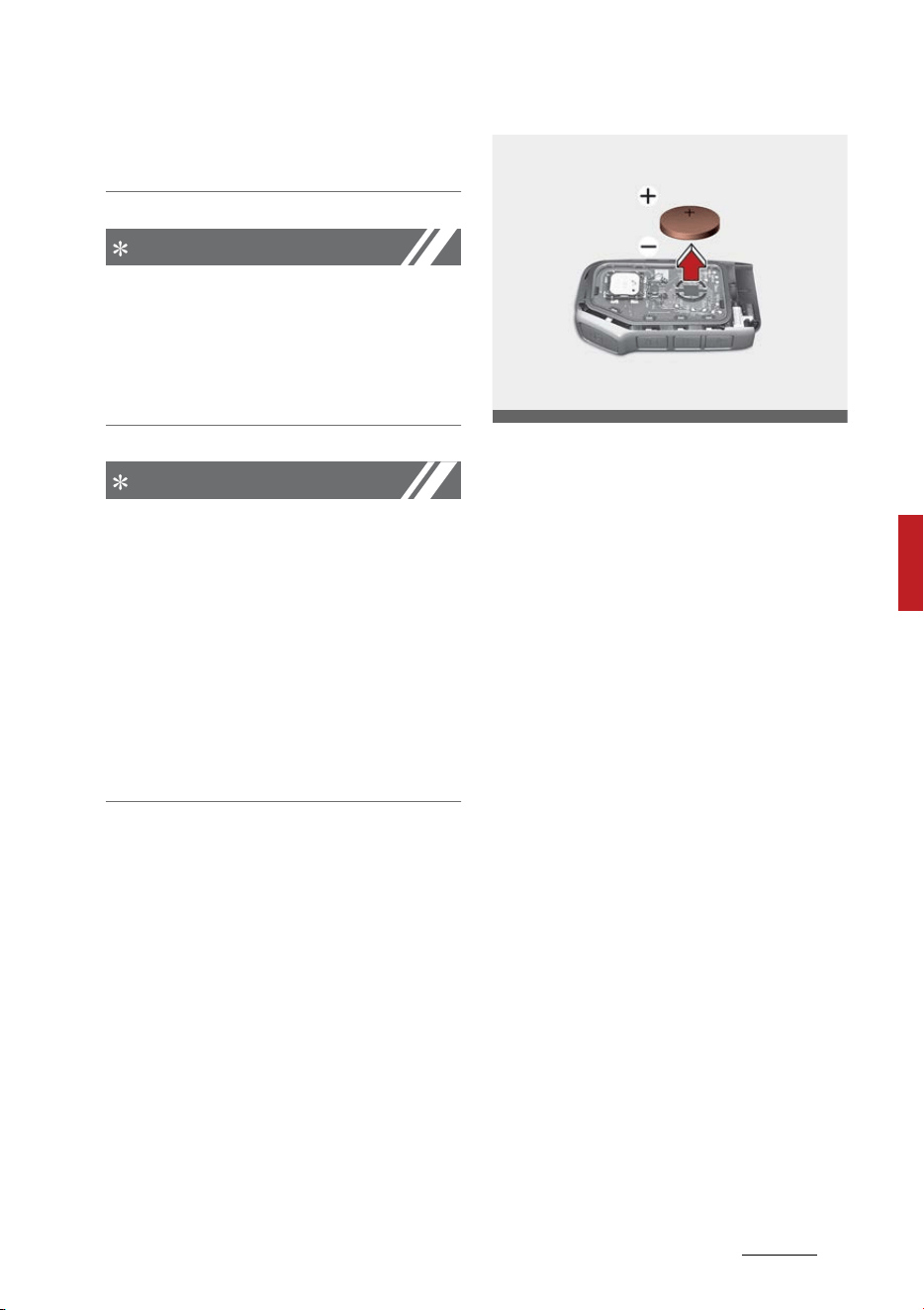
11
5
5
Features of your vehicle Keys
䳜 Table lamps
䳜 Induction cookers
NOTICE
If you have to leave the vehicle's key
with a parking attendant, remove
the mechanical key for your own
use and provide the attendant with
the electronic key only.
NOTICE
When bringing a smart key onto an
airplane, make sure you do not
press any button on the key while
inside the cabin. If you are carrying
the key in your bag etc., make sure
that the buttons cannot be pressed
accidentally. If you press a button,
the key may emit radio waves that
could interfere with the operation of
the aircraft.
Battery replacement
The smart key uses a 3 volt lithium
battery which will normally last for
several years.
If you are unsure how to use or
replace the battery, contact an
authorized Kia dealer.
1. Detach mechanical key from your
smart key.
2. Pry open the key cover.
3. Replace the smart key cover with
a new battery. (CR2032) When
replacing the battery, make sure
the battery position is correct.
4. Install the battery in the reverse
order of removal.
For smart key replacement, visit an
authorized Kia dealer.
The smart key is designed to give
you years of trouble-free use, how
-
ever it can malfunction if exposed to
moisture or static electricity. If you
are unsure how to use or replace
the battery, contact an authorized
Kia dealer.
Using the wrong battery can cause
the smart key to malfunction. Be
sure to use the correct battery.
OSK3048402NR

Features of your vehicle
125
Keys
An inappropriately dis
-
posed battery can be
harmful to the environ
-
ment and human health. Dispose
the battery according to your local
law(s) or regulation.
CAUTION
Smart key damage
The smart key can malfunction if
dropped, exposed to moisture,
static electricity, heat or direct sun
-
light.
This device complies with Part 15
of the FCC rules.
Operation is subject to the following
two conditions:
1. This device may not cause harm
-
ful interference.
2. This device must accept any
interference received, including
interference that may cause
undesired operation.
NOTICE
Changes or modifications not
expressly approved by the party
responsible for compliance could
void the user's authority to operate
the equipment. If the smart key is
inoperative due to changes or modi
-
fications not expressly approved by
the party responsible for compli
-
ance, it will not be covered by your
manufacturer's vehicle warranty.

13
5
5
Features of your vehicle Immobilizer system
Immobilizer system
Smart key immobilizer system
The immobilizer system protects
your vehicle from theft. If an
improperly coded key (or other
device) is used, the vehicle's power
system is disabled.
When the ENGINE START/STOP
button is placed in the ON position,
the immobilizer system indicator
should come on briefly, then go off.
If the indicator starts to blink, the
system does not recognize the cod
-
ing of the key.
Place the ENGINE START/STOP
button in the OFF position, then
place the ENGINE START/STOP
button in the ON position again.
If the system repeatedly does not
recognize the coding of the key,
contact your Kia dealer.
Do not attempt to alter this system
or add other devices to it. Electrical
problems could result that may
make your vehicle inoperable.
To deactivate the immobilizer sys
-
tem
Change the ENGINE START/STOP
button to the ON position.
To activate the immobilizer system
Change the ENGINE START/STOP
button to the OFF position. The
immobilizer system activates auto
-
matically. Without a valid smart key
for your vehicle, the engine will not
start.
NOTICE
When starting the vehicle, do not
use the key with other immobilizer
keys around. Otherwise, the vehicle
may not start or may stop soon
after it starts. Keep each key sepa
-
rate in order to avoid a starting
malfunction.
NOTICE
If you need additional keys or lose
your keys, contact an authorized Kia
dealer.
This device complies with Part 15
of the FCC rules.
Operation is subject to the following
two conditions:
1. This device may not cause harm
-
ful interference.
2. This device must accept any
interference received, including
interference that may cause
undesired operation.
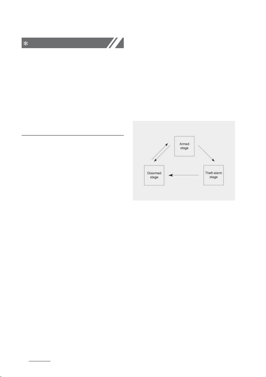
Features of your vehicle
145
Theft-alarm system
NOTICE
Changes or modifications not
expressly approved by the party
responsible for compliance could
void the user's authority to operate
the equipment. If the smart key is
inoperative due to changes or modi
-
fications not expressly approved by
the party responsible for compli
-
ance, it will not be covered by your
manufacturer's vehicle warranty.
Theft-alarm system
This system is designed to provide
protection from unauthorized entry
into the vehicle.
This system is operated in three
stages:
䳜 Armed stage
䳜 Theft-alarm stage
䳜 Disarmed stage
If triggered, the system provides an
audible alarm with blinking of the
hazard warning lights.
Armed stage
Using the smart key
Park the vehicle and stop the
engine. Arm the system as
described below.
1. Turn off the engine.
2. Make sure that all doors, the hood
and liftgate are closed and
latched.
3. Lock the doors by pressing the
button of the front outside door
handle with the smart key in your

15
5
5
Features of your vehicle Theft-alarm system
possession. After completion of
the steps above, the hazard
warning lights will operate once to
indicate that the system is
armed. If any door (or liftgate) or
hood remains open, the hazard
warning lights and the chime will
not operate and the theft-alarm
will not arm. If all doors and lift
-
gate and hood are closed after
the lock button is pressed, the
hazard warning lights blink once.
The system can also be armed by
locking the doors with the key
from the front doors; however,
the hazard warning lights will not
blink using this method.
4. Lock the doors by pressing the
lock button on the smart key.
After completion of the steps
above, the hazard warning lights
will operate once to indicate that
the system is armed.
NOTICE
The theft-alarm system can be
deactivated by an authorized Kia
dealer.
If you want this feature, consult an
authorized Kia dealer.
NOTICE
Do not arm the system until all pas
-
sengers have left the vehicle. If the
system is armed while a passen
-
ger(s) remains in the vehicle, the
alarm may be activated when the
remaining passenger(s) leaves the
vehicle. If any door (or liftgate) or
hood is opened within 30 seconds
after the system enters the armed
stage, the system will be disarmed
to prevent unnecessary alarm.
Theft-alarm stage
The alarm will be activated if any of
the following occurs while the sys
-
tem is armed.
䳜 A front or rear door is opened
without using the smart key.
䳜 The liftgate is opened without
using the smart key.
䳜 The hood is opened.
The horn will sound and the hazard
warning lights will blink continuously
for approximately 27 seconds, and
repeat the horn 3 times unless the
system is disarmed. To turn off the
system, unlock the doors with the
smart key.
Disarmed stage
The system will be disarmed when:
Smart key
䳜 The door unlock button is
pressed.
䳜 The button of the front outside
door is pressed while carrying the
smart key.

Features of your vehicle
165
Theft-alarm system
䳜 The engine is started. (within 3
seconds)
After pressing the unlock button,
the hazard warning lights will blink
and the chime will sound twice (in
smart key) to indicate that the sys
-
tem is disarmed.
After pressing the unlock button, if
any door (or liftgate) is not opened
within 30 seconds, the system will
be rearmed.
NOTICE
䳜 Avoid trying to start the engine
while the alarm is activated. The
vehicle starting motor is disabled
during the theft-alarm stage.
䳜 If you lose your keys, consult your
authorized Kia dealer.
CAUTION
Adjusting alarm system
Do not change, alter or adjust the
theft alarm system in your vehicle.
Improper installation of the alarm
system could damage the vehicle or
cause the system to malfunction.
NOTICE
Malfunctions caused by improper
alterations, adjustments or modifi
-
cations to the theft-alarm system
are not covered by your vehicle
manufacturer warranty.
This device complies with Part 15
of the FCC rules.
Operation is subject to the following
two conditions:
1. This device may not cause harm
-
ful interference.
2. This device must accept any
interference received, including
interference that may cause
undesired operation.
NOTICE
Changes or modifications not
expressly approved by the party
responsible for compliance could
void the user's authority to operate
the equipment. If the smart key is
inoperative due to changes or modi
-
fications not expressly approved by
the party responsible for compli
-
ance, it will not be covered by your
manufacturer's vehicle warranty.
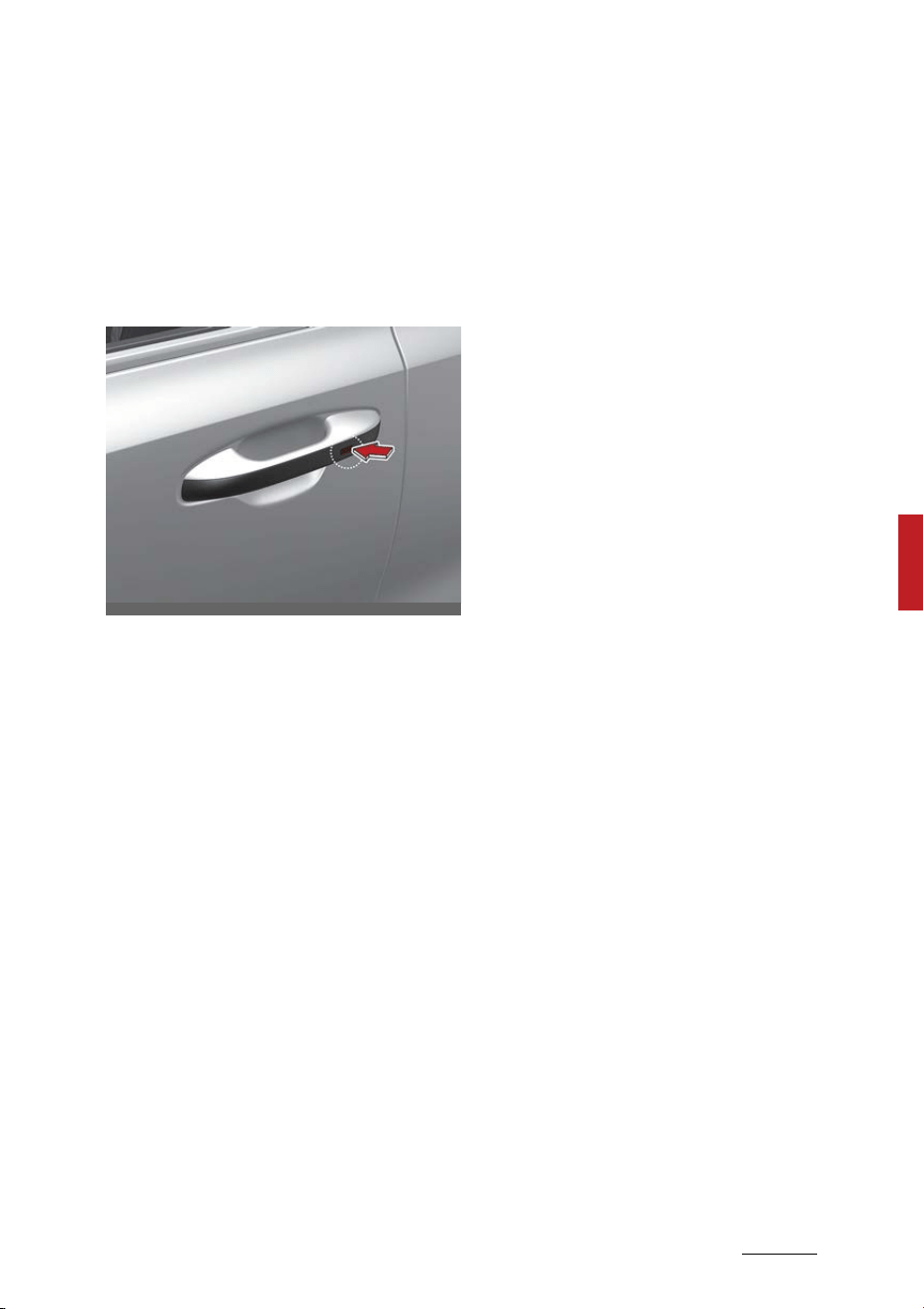
17
5
5
Features of your vehicle Door locks
Door locks
Know how to use the door lock so
that you can lock or unlock the door
if necessary.
With the smart key
Carrying the smart key, you may
lock and unlock the vehicle doors
(and liftgate). Also, you may start
the engine. Refer to the following
for more details.
Locking
Pressing the button of the front
driver side door handles with all
doors closed and any door unlocked,
locks all the doors. If all doors and
engine hood are closed, the hazard
warning lights will blink once to indi
-
cate that all doors are locked.
The button will only operate when
the smart key is within 28~40 inches
(0.7~1 m) from the driver side door
handle. If you want to make sure
that a door has locked or not, you
should pull the driver side door han
-
dle.
Even though you press the driver
side door handle buttons, the doors
will not lock and the chime will
sound for 3 seconds if any of fol
-
lowing occur:
䳜 The smart key is in the vehicle.
䳜 The ENGINE START/STOP button
is in the ACC or ON position.
䳜 Any door except the liftgate is
open.
Unlocking
Pressing the button of the front
driver side door handles with all
doors closed and locked, unlocks all
the doors. The hazard warning
lights blink twice to indicate that all
doors are unlocked.
The button will only operate when
the smart key is within 28~40 inches
(0.7~1 m) from the front driver side
door handle.
When the smart key is recognized in
the area of 28~40 inches (0.7~1 m)
from the front driver side door han
-
dle, other people can also open the
door without possession of the
smart key.
After pressing the button, the doors
will lock automatically unless you
open any door within 30 seconds.
OMQ4040522
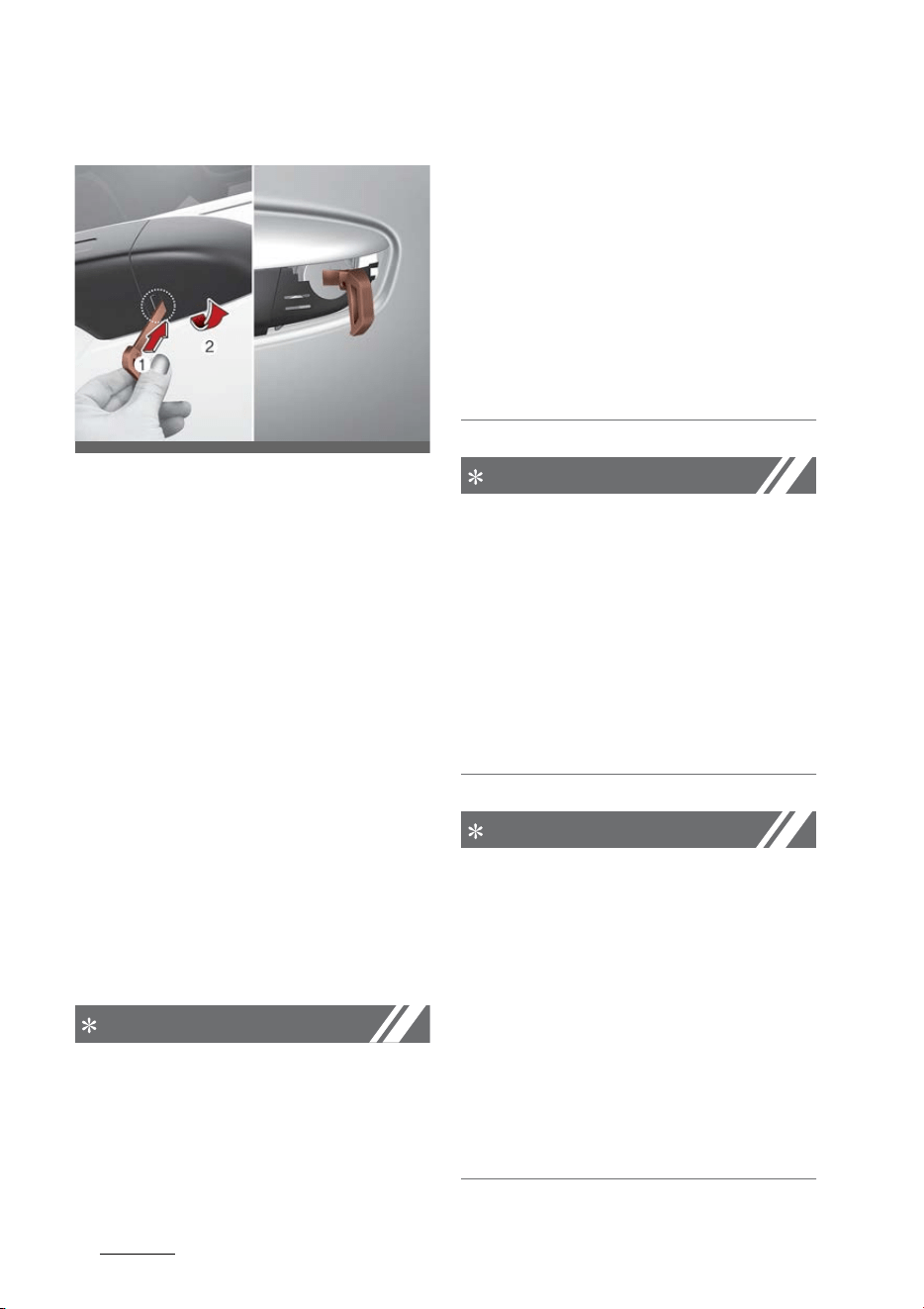
Features of your vehicle
185
Door locks
With the mechanical key
1. Pull out the door handle.
2. Press the lever (1) located inside
the bottom part of the cover with
a key or flat-head screwdriver.
3. Push out the cover (2) while
pressing the lever.
4. Turn the key toward the rear of
the vehicle to unlock and toward
the front of the vehicle to lock
(only the driver's door can be
locked/unlocked).
䳜 Doors can also be locked and
unlocked with the transmitter.
䳜 Once the doors are unlocked, they
may be opened by pulling the
door handle.
䳜 When closing the door, push the
door by hand. Make sure the
doors are closed securely.
NOTICE
䳜 When locking the door with a
mechanical key, be aware that
only the driver's door can be
locked/unlocked.
䳜 To lock all doors, operate the cen
-
tral lock switch inside the vehicle.
Open the car door using the inner
handle, then close the door and
lock the driver's door with a
mechanical key.
䳜 Refer to "Operating door locks
from inside the vehicle" on page
5-19 to lock from inside the vehi
-
cle.
NOTICE
Be careful not to lose or scratch the
cover when removing it.
When the key cover freezes and
does not open, tap it lightly or indi
-
rectly warm (hand temperature,
etc.) it up.
Do not apply excessive force to the
door and door handle. It may be
damaged.
NOTICE
䳜 In cold and wet climates, door lock
and door mechanisms may not
work properly due to freezing
conditions.
䳜 If the door is locked/unlocked
multiple times in rapid succession
with either the vehicle key or door
lock switch, the system may stop
operating temporarily in order to
protect the circuit and prevent
damage to system components.
OMQ4AH040543
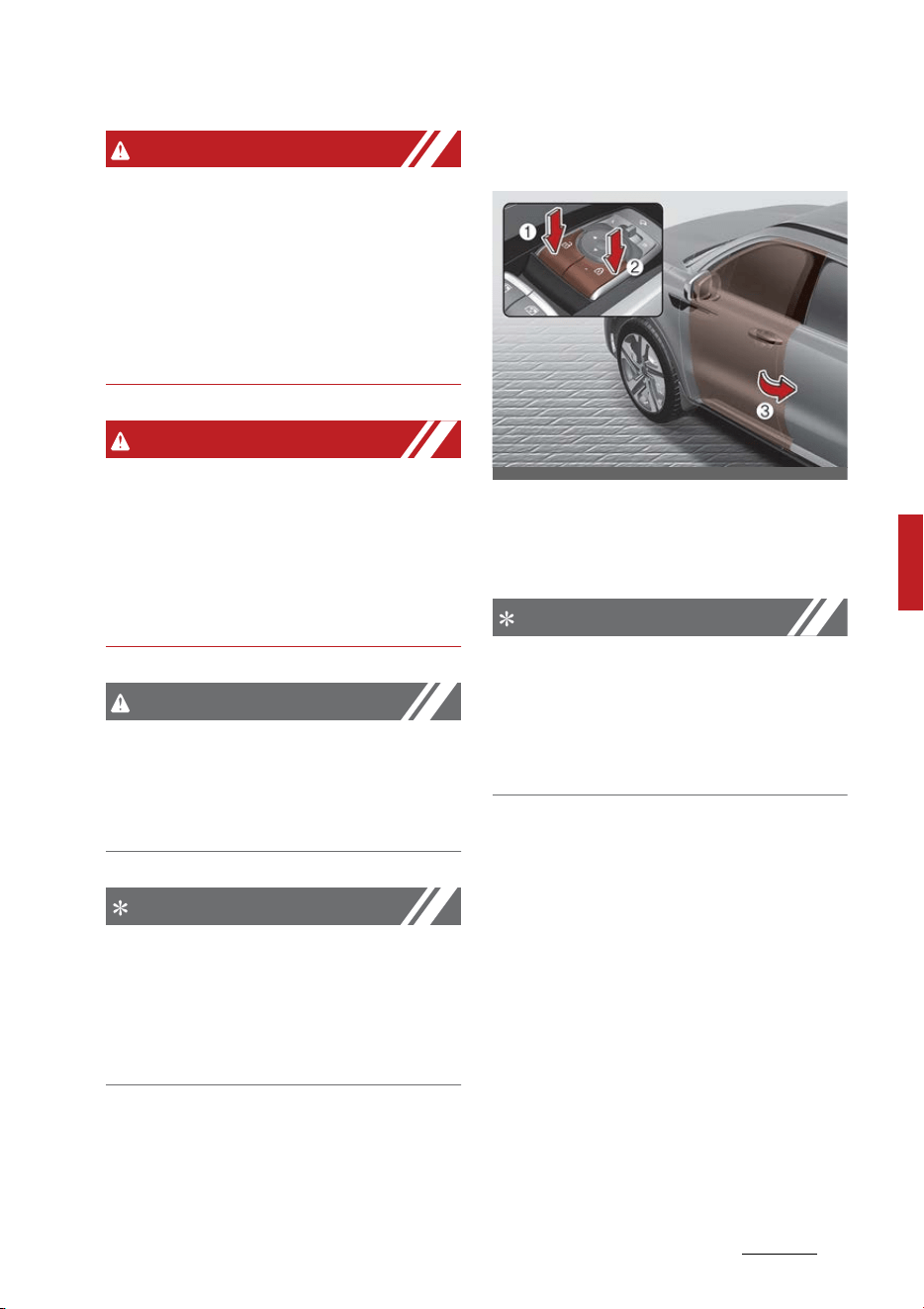
19
5
5
Features of your vehicle Door locks
WARNING
䳜 Securely close your door before
you begin driving. Failure to fully
close your door may cause it to
open during vehicle operation.
䳜 Keep your body out of the way of
the closing door to prevent inju
-
ries.
WARNING
If any passengers must remain in
the vehicle while it is very hot or cold
outside, there is risk of injuries or
danger to life. Do not lock the vehi
-
cle from the outside when there are
passengers in the vehicle.
CAUTION
Do not unnecessarily open and close
the door repeatedly or with exces
-
sive force. Such action can damage
the vehicle door.
NOTICE
Always place the ENGINE START/
STOP button in the OFF position,
engage the parking brake, close all
windows, and lock all doors when
leaving your vehicle unattended.
䳜 To lock a door without the key,
push the central door lock button
(2) when the ENGINE START/STOP
button is in the OFF position and
close the door (3).
䳜 If you lock the door with the cen
-
tral door lock button (2), all vehi
-
cle doors will lock automatically.
NOTICE
Always turn the ENGINE START/
STOP button off, engage the park
-
ing brake, close all windows, and
lock all doors when leaving your
vehicle unattended.
Operating door locks from inside
the vehicle
You can operate door locks with the
door lock handle or central door lock
switch.
OMQ4H040019
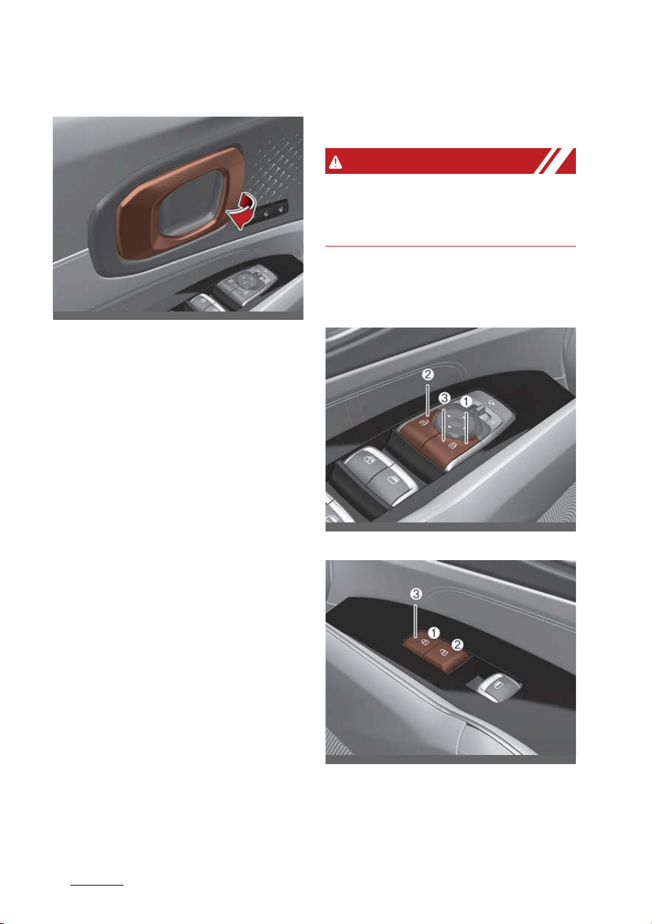
Features of your vehicle
205
Door locks
With the door handle
䳜 Front door
If the inner door handle is pulled
when the door is locked, the door
will unlock and open.
䳜 Rear door
If the inner door handle is pulled
once when the door is locked, the
door will unlock.
If the inner door handle is pulled
once more, the door will open.
Door lock malfunction
If a power door lock ever fails to
function while you are in the vehicle,
try one or more of the following
techniques to exit:
䳜 Operate the door unlock feature
repeatedly (both electronic and
manual) while simultaneously
pulling on the door handle.
䳜 Operate the other door locks and
handles, front and rear.
䳜 Lower a front window and use the
key to unlock the door from out
-
side.
䳜 Move to the cargo area and open
the liftgate.
WARNING
Do not pull the inner door handle of
driver's (or passenger's) door while
the vehicle is moving.
With central door lock switch
Driver side
Passenger side
1. Door Lock
2. Door Unlock
3. Doors indicating light
OMQ4040006
OMQ4AH040416
OMQ4AH040418

21
5
5
Features of your vehicle Door locks
Operate by pressing the central
door lock switch.
䳜 To lock all vehicle doors, press the
central door lock switch (1) of
driver and passenger side.
䳜 To unlock all vehicle doors, press
central door unlock switch (2) of
driver and passenger side.
When all vehicle doors are locked,
the indicating lights (3) on the
driver's door and passenger's door
will turn on. If any door is unlocked,
it would go off.
If the smart key is in the vehicle and
any door is opened, the doors will
not lock even though the central
door lock switch is pressed.
WARNING
Doors
䳜 The doors should always be fully
closed and locked while the vehicle
is in motion to prevent accidental
opening of the door. Locked doors
will also discourage potential
intruders when the vehicle stops
or slows down.
䳜 Be careful when opening doors
and watch for vehicles, motorcy
-
cles, bicycles or pedestrians
approaching the vehicle in the
path of the door. Opening a door
when something is approaching
can cause damage or injury.
NOTICE
Unlocked vehicles
Leaving your vehicle unlocked can
invite theft or possible harm to you
or others from someone hiding in
your vehicle while you are gone.
Always turn the ENGINE START/
STOP button off, close all windows
and lock all doors when leaving your
vehicle unattended.
WARNING
Unattended children/animals
Never leave children or animals
unattended in your vehicle. An
enclosed vehicle can become
extremely hot, causing death or
severe injury to unattended chil
-
dren or animals who cannot escape
the vehicle.
Door lock/unlock features
The vehicle is equipped with door
lock/unlock features for the safety
and convenience of passengers.
Impact sensing door unlock system
All doors will automatically unlock
when an impact causes the air bags
to deploy.
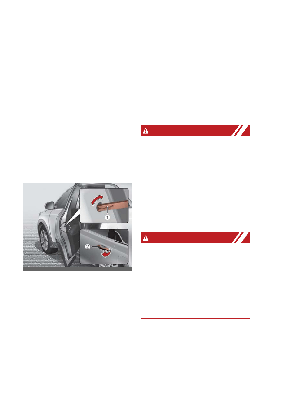
Features of your vehicle
225
Door locks
Speed sensing door lock system
All doors will automatically lock
after the vehicle speed exceeds 15
km/h.
You can activate or deactivate the
auto door lock/unlock features in
the vehicle. Refer to "User settings
mode" on page 5-93.
Child-protector rear door lock (if
equipped)
The child safety lock is provided to
help prevent children from acciden
-
tally opening the rear doors from
inside the vehicle.
The rear door safety locks should be
used whenever children are in the
vehicle.
The child safety lock is located on
the edge of each rear door. When
the child safety lock is in the lock
position (1), the rear door will not
open if the inner door handle is
pulled.
To lock the child safety lock, insert a
key (or screwdriver) into the hole
and turn it to the lock position.
To allow a rear door to be opened
from inside the vehicle, unlock the
child safety lock.
To open the rear door, pull the out
-
side door handle (2).
WARNING
Rear door locks
If children accidentally open the rear
doors while the vehicle is in motion,
they could fall out and be severely
injured or killed. To prevent children
from opening the rear doors from
the inside, the rear door safety locks
should be used whenever children
are in the vehicle.
WARNING
䳜 The system does not detect every
obstacle approaching the vehicle
exit.
䳜 The driver and passenger are
responsible for the accident
occurred while exiting the vehicle.
Always check the surrounding
before you exit the vehicle.
Electronic child safety lock system
(if equipped)
If you push the electronic child
safety lock switch and the indicator
OMQ4H040021
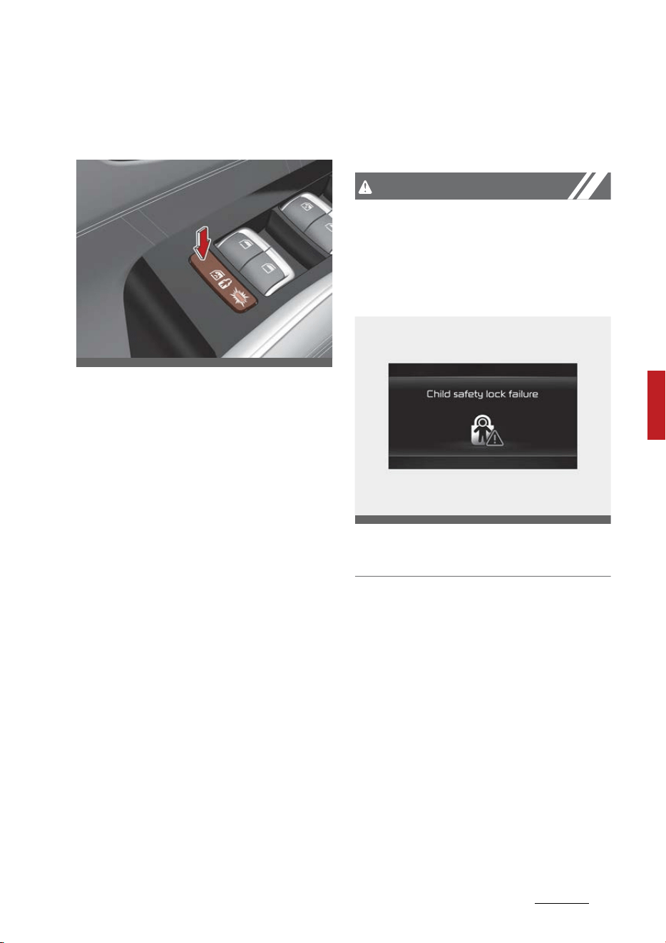
23
5
5
Features of your vehicle Door locks
illuminates, rear passengers cannot
open the rear door from inside the
vehicle.
To cancel the electronic child safety
lock, push the electronic child safety
lock switch one more time and then
the indicator turns off.
Safe Exit Assist is operated when
the electronic child safety lock is
activated and SEA is selected in the
cluster. However, SEA does not
automatically activate the electronic
child safety lock system.
The electronic child safety lock is
always on when the ENGINE START/
STOP button is in the ON and for
approximately 3 minutes after the
engine is turned off.
If your vehicle is equipped with the
Electronic child safety lock, the
Child-protector rear door locks,
which are manually operated, are
not provided.
If electronic child safety lock is acti
-
vated, rear passenger cannot open
or close the rear window also. For
more details, refer to "Windows" on
page 5-42.
CAUTION
If the Electronic child safety lock is
not operated when pushing the
Electronic child safety lock switch,
the message is displayed and the
alarm will sound.
If this occurs, have the system
checked by an authorized Kia dealer.
In case of an emergency
If the electrical power door lock
switch is not operating (e.g., dead
car battery) the only way to lock the
door(s) is with the mechanical key
from the outside key hole.
Doors without an outside key hole
can be locked as follows:
1. Open the door.
2. Insert the key into the emergency
door lock hole and turn the key to
the lock position as shown.
OMQ4AH040008
OMQ4040107L
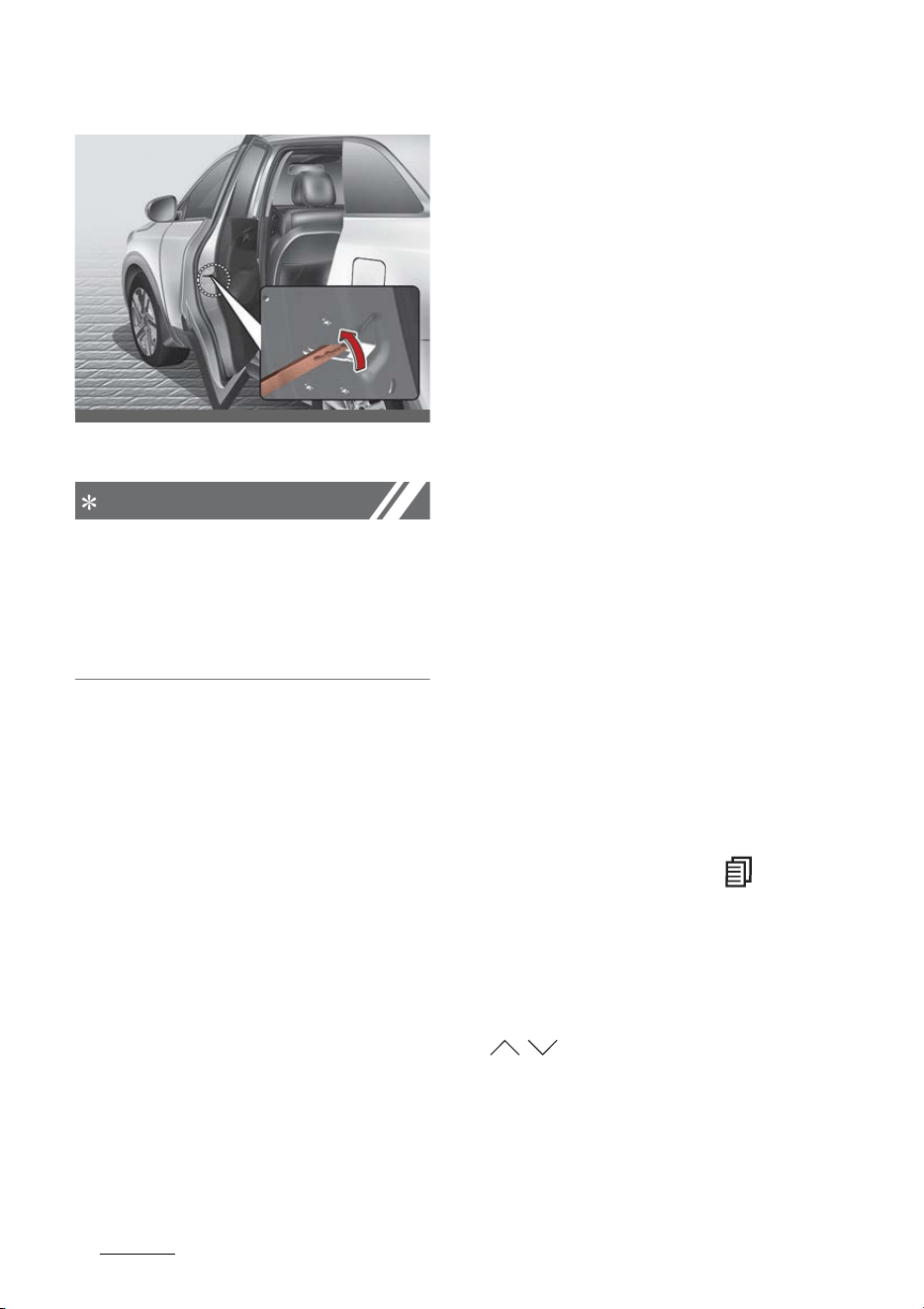
Features of your vehicle
245
Door locks
3. Close the door securely.
NOTICE
If the electrical power to door lock
switch is not operating (e.g., dead
car battery) and the liftgate is
closed, you will not be able to open
the liftgate until power is restored.
Rear Occupant Alert (ROA) System
(if equipped)
The Rear Occupant Alert (ROA) is
provided to help prevent exiting the
vehicle with a rear passenger left in
the vehicle.
1st alert
When you open the front door after
opening and closing the rear door
and turning off the engine, the
"Check rear seats" warning message
appears on the cluster.
2nd alert
䳜 After the 1st alert, the 2nd alert
operates when any movement is
detected in the rear seat after
the driver's door is closed and all
the doors are locked. The horn will
activate for about 25 seconds. If
the system continues to detect a
movement the alert operates up
to 8 times.
䳜 Unlock the door with the smart
key to stop the alert.
䳜 The system detects movement in
the vehicle for 24 hours after the
door is locked.
The 2nd alert is activated only after
the prior activation of the 1st alert.
Operation
You can activate or deactivate the
ROA from the User Settings mode in
the cluster LCD display.
The option can be found under the
following menu:
1. Press the MODE button ( ) sev
-
eral times on the steering wheel
until 'User Settings' menu appears
on the LCD.
2. Select 'Convenience → Rear Occu
-
pant Alert' with the MOVE switch
( / ) and the OK button on the
steering wheel.
If your vehicle is equipped with the
infotainment system, the option can
be found under the following menu:
OMQ4040020R
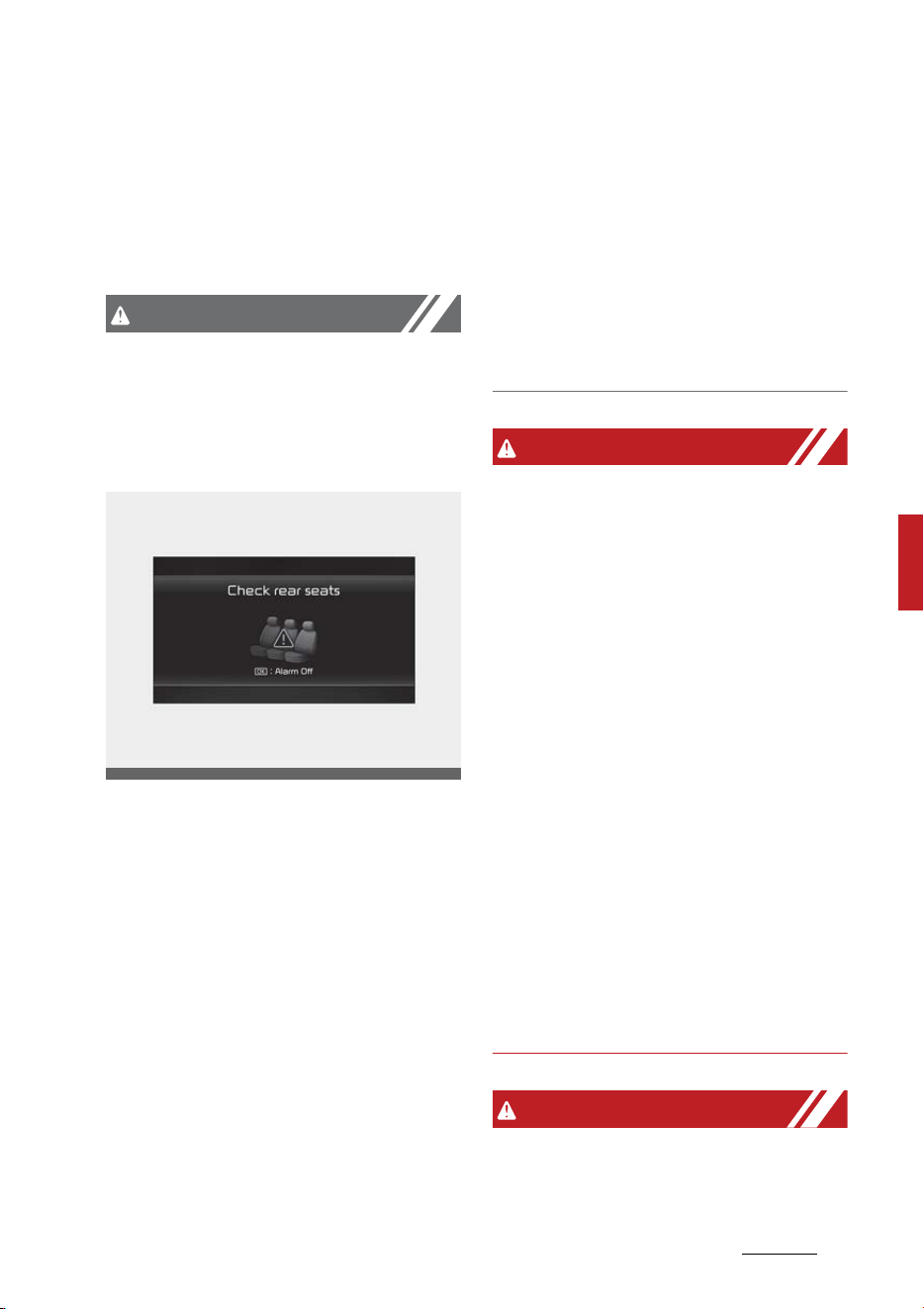
25
5
5
Features of your vehicle Door locks
1. Press the SETUP button of the
infotainment system.
2. Press 'Vehicle → Convenience →
Rear Occupant Alert' on the info
-
tainment system screen.
CAUTION
䳜 Make sure that all the windows
are closed. If the window is open,
the alert may activate by the
sensor detecting an unintended
movement (e.g., wind or bugs).
䳜 If you do not want to use the Rear
Occupant Alert (ROA) system,
press OK button on the steering
wheel when the 1st alert is dis
-
played on the cluster. Doing so will
deactivate the 2nd alert once.
䳜 If boxes or objects are stacked in
the vehicle, the system may not
detect the obstacle. Also, the
warning may generate if the box
or object falls off.
䳜 The sensor may not operate nor
-
mally if the senor is obscured by
foreign substances.
䳜 The alert may activate if move
-
ment in the driver or passenger
seat is detected.
䳜 The alert may activate with the
doors locked due to car wash or
surrounding vibration or noise.
䳜 Inside movement detection is
stopped under remote start sta
-
tus.
WARNING
䳜 Even if your vehicle is equipped
with the Rear Occupant Alert
(ROA) system, always make sure
you check the rear seat before
you get off the vehicle.
The alert may not operate if:
- The movement does not con
-
tinue for a certain period of
time or the movement is small.
- If a child sits on a vehicle seat
without a child car seat.
- The rear passenger is covered
with an obstacle such as a blan
-
ket.
- Also, always be cautious of the
passenger's safety as the
detection function and 2nd
alert may not operate depend
-
ing on the surrounding environ
-
ment and certain conditions.
WARNING
The door lock system may not work
if the electrical system is compro
-
OMQ4AH040553
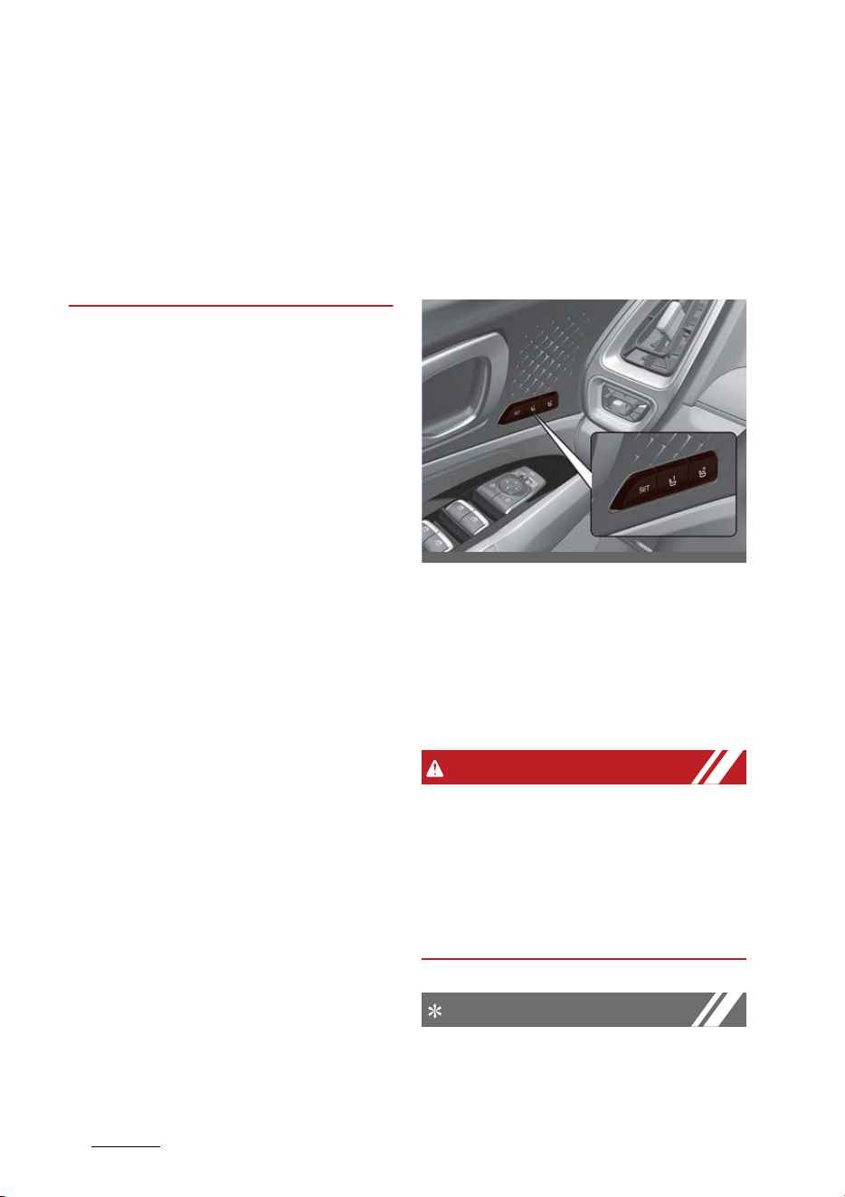
Features of your vehicle
265
Driver Position Memory System
mised. Accordingly, please train chil
-
dren passengers regarding how to
open the car door manually before
an emergency situation arises. That
way, they would be able to open the
door manually in the event an
emergency situation arises.
Driver Position Memory System
(if equipped)
The Driver Position Memory System
is provided to store and recall the
following memory settings with a
simple button operation.
䳜 Driver's seat position
䳜 Outside rear view mirror position
䳜 Instrument panel illumination
intensity
䳜 Head Up Display (HUD) position
and brightness (if equipped)
WARNING
Never attempt to operate the driver
position memory system while the
vehicle is moving.
This could result in loss of control,
and an accident causing death, seri
-
ous injury, or property damage.
NOTICE
䳜 If the battery is disconnected, the
memory settings will be erased.
OMQ4040004

27
5
5
Features of your vehicle Driver Position Memory System
䳜 If the Driver Position Memory
System does not operate nor
-
mally, have the system checked
by an authorized Kia dealer.
Storing memory positions
1. The ENGINE START/STOP button
is in the ON position.
2. Adjust the driver's seat position,
outside rear view mirror position
and instrument panel illumination
intensity to the desired position.
3. Press the SET button. The system
will beep once and notify you
"Press button to save settings"on
the LCD display.
4. Press one of the memory buttons
(1 or 2) within 4 seconds. The
system will beep twice when the
memory has been successfully
stored.
5. "Settings 1 (or 2) saved" will
appear on the LCD display.
Recalling memory positions
1. The ENGINE START/STOP button
is in the ON position.
2. Press the desired memory but
-
ton (1 or 2). The system will beep
once, and then the driver's seat
position, outside rear view mirror
position, instrument panel illumi
-
nation intensity and head-up dis
-
play height/brightness will
automatically adjust to the stored
positions.
3. "Settings 1 (or 2) applied" will
appear on the LCD display.
䳜 While recalling the "1" memory
position, pressing the SET or 1
button temporarily stops the
adjustment of the recalled mem
-
ory position. Pressing the 2 but
-
ton recalls the "2" memory
position.
䳜 While recalling the "2" memory
position, pressing the SET or 2
button temporarily stops the
adjustment of the recalled mem
-
ory position. Pressing the 1 but
-
ton recalls the "1" memory
position.
䳜 While recalling the stored posi
-
tions, pressing one of the control
buttons for the driver's seat, out
-
side rear view mirror, or instru
-
ment panel illumination will cause
the movement of that component
to stop and move in the direction
that the control button is pressed.
Driver position memory system
reset
If the Driver position memory sys
-
tem does not work properly, initial
-
ize the system as follows.
How to initialize:
1. Stop the vehicle and open the
driver's door with the ENGINE
START/STOP button in the ON
position and the vehicle shifted to
P (Park).

Features of your vehicle
285
Driver Position Memory System
2. Pull the driver's seat forward as
far as possible and have the seat
-
back upright as much as possible
using the driver's seat forward/
backward adjustment and seat
-
back angle (recline) switches.
3. Push the SET button and seat
forward movement switch for 2
seconds simultaneously.
Initialization in the process:
1. Initialization begins as the alarm
sounds.
2. The seat and seatback will auto
-
matically move backwards. The
alarm sound will continue while
the system is in operation.
3. Initialization will be complete
after the seat and seatback move
to the center with an alarm
sound. If, however, cases as fol
-
lows occur, the initialization pro
-
cess will come to a stop and the
alarm sound will stop as well.
䳜 When pushing driving position
memory system button
䳜 When pushing driver's seat height
adjustment switch
䳜 When shifting from P (Park) to
other positions
䳜 When driving speed exceeds 3
km/h
䳜 When the driver's door is closed
Easy access function
The system will move the driver's
seat automatically as follows:
With smart key system
䳜 It will move the driver's seat rear
-
ward when the ENGINE START/
STOP button is in the OFF position
and the driver's door is opened.
䳜 It will move the driver's seat for
-
ward when the vehicle is turned
ON or the driver's door is closed
with the smart key with you.
You can activate or deactivate the
Easy Access Function from the User
Settings Mode on the LCD display.
For more details, refer to "LCD dis
-
play" on page 5-90. If your vehicle is
equipped with additional navigation,
please refer to the infotainment
system manual separately supplied.
NOTICE
Upward/downward movement of
the seat may not work when pas
-
sengers get on/off the vehicle in
order to prevent foot injuries in cer
-
tain places.
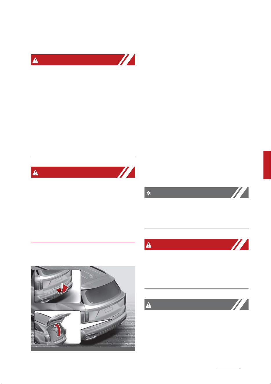
29
5
5
Features of your vehicle Liftgate
Liftgate
WARNING
Exhaust fumes
If you drive with the liftgate open,
you will draw dangerous exhaust
fumes into your vehicle which can
cause serious injury or death to
vehicle occupants.
If you must drive with the liftgate
open, keep the air vents and all win
-
dows open so that additional out
-
side air comes into the vehicle.
WARNING
Rear cargo area
Occupants should never ride in the
rear cargo area where no restraints
are available. To avoid injury in the
event of an accident or sudden
stops, occupants should always be
properly restrained.
Opening the liftgate
䳜 The liftgate is locked or unlocked
when all doors are locked or
unlocked with the transmitter (or
smart key) or central door lock
switch.
䳜 Only the liftgate is unlocked if the
liftgate unlock button on the
transmitter or smart key is
pressed for approximately 1 sec
-
ond.
䳜 If unlocked, the liftgate can be
opened by pressing the handle
and pulling it up.
䳜 Once the liftgate is opened and
then closed, the liftgate locks
automatically. (All doors must be
locked.)
NOTICE
In cold and wet climates, door lock
and door mechanisms may not work
properly due to freezing conditions.
WARNING
The liftgate swings upward. Make
sure no objects or people are near
the rear of the vehicle when opening
the liftgate.
CAUTION
Make certain that you close the lift
-
gate before driving your vehicle.
Possible damage may occur to the
liftgate gas lifters and attached
OMQ4AH041009
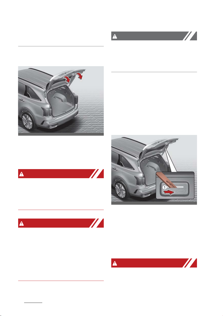
Features of your vehicle
305
Liftgate
hardware if the liftgate is not closed
prior to driving.
Closing the liftgate
䳜 To close the liftgate, lower and
push down the liftgate firmly.
Make sure that the liftgate is
securely latched.
WARNING
Make sure your hands, feet and
other parts of your body are safely
out of the way before closing the
liftgate.
WARNING
Exhaust fumes
The liftgate lid should be always
kept completely closed while the
vehicle is in motion. If it is left open
or ajar, poisonous exhaust gases
may enter the car and serious ill
-
ness or death may result.
CAUTION
Make sure nothing is near the lift
-
gate latch and striker while closing
the liftgate. It may damage the lift
-
gate's latch.
Emergency liftgate safety release
Your vehicle is equipped with the
emergency liftgate safety release
lever located on the bottom of the
liftgate. When someone is inadver
-
tently locked in the luggage com
-
partment.
The liftgate can be opened by doing
as follows:
1. Input the mechanical key into the
hole.
2. Push the mechanical key to the
right (1).
3. Push up the liftgate.
WARNING
䳜 You and your passengers must be
aware of the location of the
Emergency Liftgate Safety
OMQ4PH041486
OMQ4PH041014
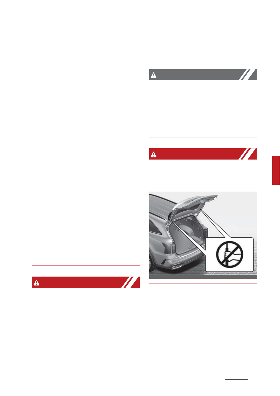
31
5
5
Features of your vehicle Liftgate
Release lever in this vehicle and
how to open the liftgate in case
you are accidentally locked in the
liftgate.
䳜 NEVER allow anyone to occupy
the liftgate of the vehicle at any
time. If the liftgate is partially or
totally latched and the person is
unable to get out, serious injury
or death could occur due to lack of
ventilation, exhaust fumes and
rapid heat build-up, or because of
exposure to cold weather condi
-
tions. The liftgate is also a highly
dangerous location in the event of
a crash because it is not a pro
-
tected occupant space but is a
part of the vehicle's crush zone.
䳜 Your vehicle should be kept locked
and the Smart Key should be kept
out of the reach of children. Par
-
ents should teach their children
about the dangers of playing in
liftgates.
䳜 Use the release lever for emer
-
gencies only.
WARNING
䳜 No one should be allowed to
occupy the cargo area of the vehi
-
cle at any time. The cargo area is
a very dangerous location in the
event of a crash.
䳜 Use the release lever for emer
-
gencies only. Use with extreme
caution, especially while the vehi
-
cle is in motion.
CAUTION
Make sure there are no people or
objects around the liftgate before
opening or closing the liftgate. Wait
until the liftgate is open fully and
stopped before loading or unloading
cargo from the vehicle.
WARNING
Do not grasp the part supporting
the liftgate (gas lifter), as this may
cause serious injury.
OMQ4PH041401
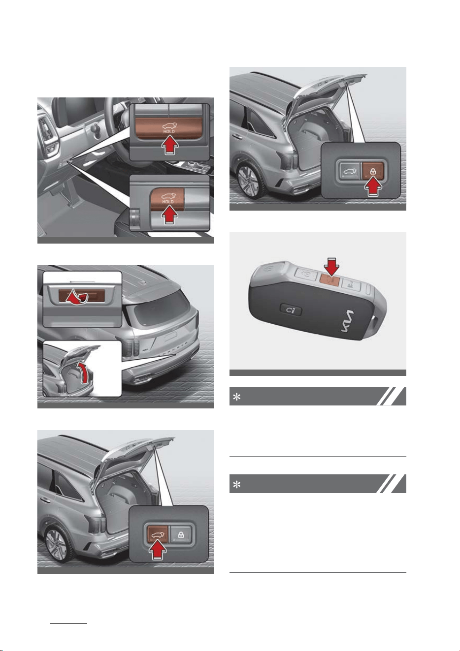
Features of your vehicle
325
Power liftgate
Power liftgate (if equipped)
1. Power liftgate open/close button
2. Power liftgate handle switch
3. Power liftgate close button
4. Power liftgate lock button
5. Power liftgate open/close button
NOTICE
If the ENGINE START/STOP button is
ON position, the power liftgate can
operate when the gear is in P (Park).
NOTICE
Do not put heavy stuffs on the
power liftgate when you operate
the power liftgate. Additional
weight on liftgate could cause dam
-
ages to the system.
OMQ4PH050262L
OMQ4AH041561
OMQ4H051031
OMQ4H051032
OMQ4041436
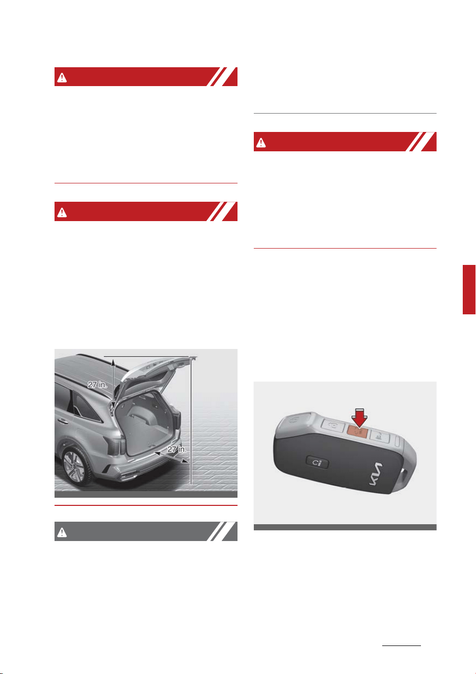
33
5
5
Features of your vehicle Power liftgate
WARNING
Never leave children or animals
unattended in your vehicle. Children
or animals might operate the power
liftgate that could result in injury to
themselves or others, or damage
the vehicle.
WARNING
Make sure that there are no people
or objects in the path of the power
liftgate (or smart liftgate) prior to
use. Serious injury, damage to the
vehicle or damage to surrounding
objects may result if contact with
the power liftgate (or smart lift
-
gate) occurs.
CAUTION
Do not close or open the power lift
-
gate manually. This may cause
damage to the power liftgate. If it is
necessary to close or open the
power liftgate manually when the
battery is discharged or discon
-
nected, do not apply excessive
force.
WARNING
Make sure there are no people or
objects around the liftgate before
opening or closing the power lift
-
gate. Wait until the liftgate is open
fully and stopped before loading or
unloading cargo from the vehicle.
Opening the liftgate
The power liftgate will open auto
-
matically by doing one of the fol
-
lowings:
䳜 Press the power liftgate open
button for approximately one
second.
OMQ4AH041488
OMQ4041436
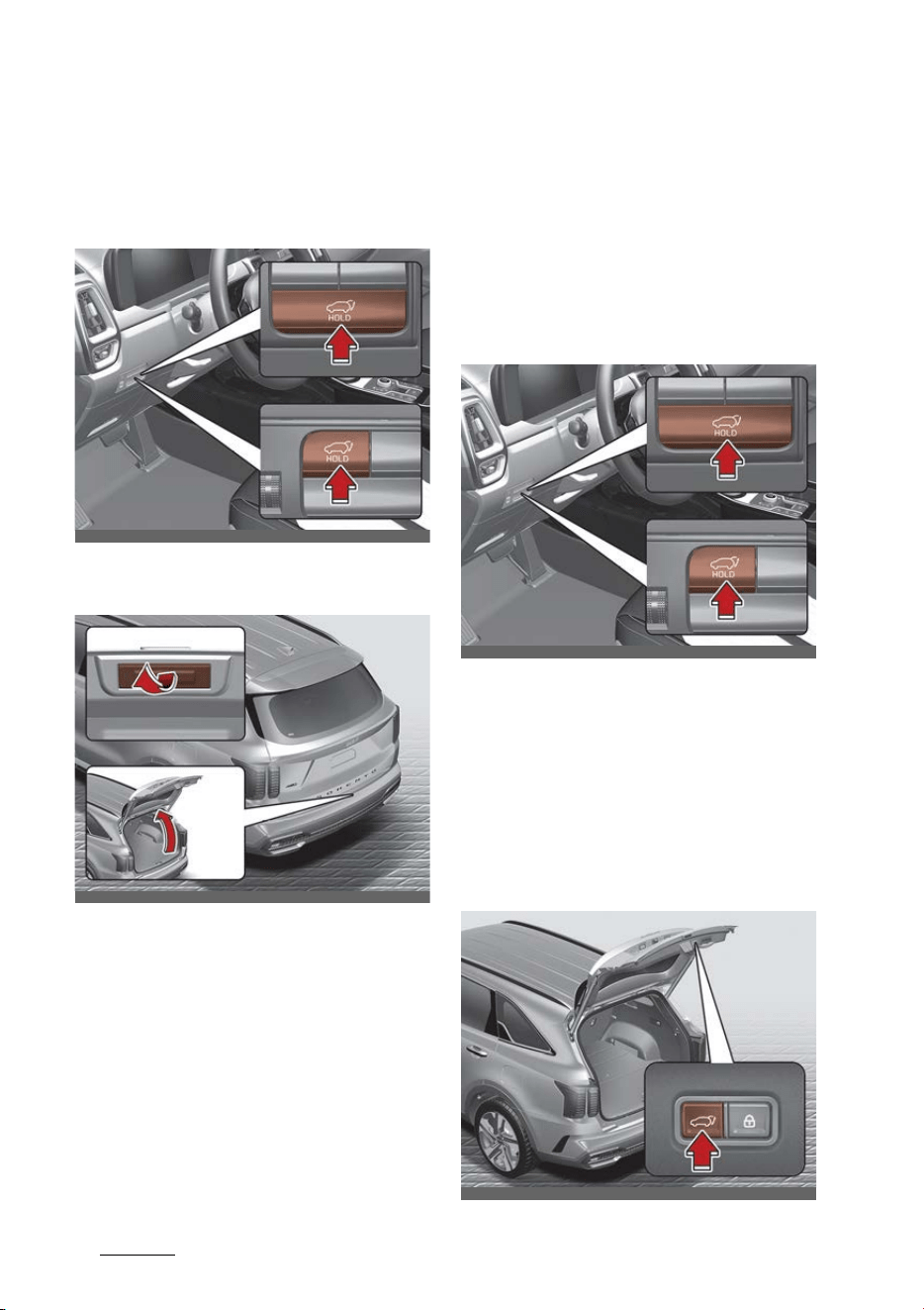
Features of your vehicle
345
Power liftgate
䳜 For emergency stop while power
liftgate operating, press the
power liftgate open/close button
shortly.
䳜 Press the liftgate handle switch
carrying the smart key with you.
Closing the liftgate
The power liftgate will close auto
-
matically by doing one of the fol
-
lowing:
䳜 Press the power liftgate close
button for approximately one
second when the liftgate is
opened.
The liftgate will close and lock
automatically.
䳜 For emergency stop while power
liftgate operating, press the
power liftgate open/close button
shortly.
䳜 Press the power liftgate close
button when the liftgate is
opened.
OMQ4PH050262L
OMQ4AH041561
OMQ4PH050262L
OMQ4H051031
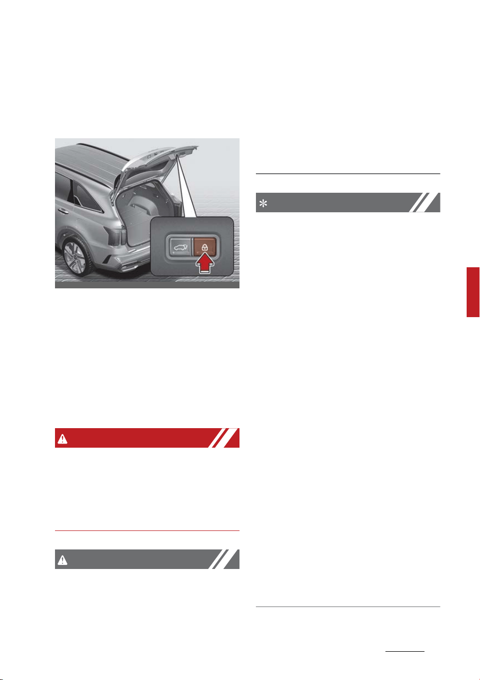
35
5
5
Features of your vehicle Power liftgate
The liftgate will close automati
-
cally.
䳜 Press the power liftgate lock but
-
ton with carrying a smart key,
when the liftgate is opened.
The liftgate will close and doors
will lock automatically.
Power liftgate non-opening condi
-
tions
The power liftgate will not open
automatically, when the vehicle is
moving more than 2 mph (3 km/h).
WARNING
The chime will sound continuously if
you drive over 2 mph (3 km/h) with
the liftgate opened. Stop your vehi
-
cle immediately at a safe place and
check if your liftgate is opened.
CAUTION
Do not operate the power liftgate
more than 5 times continuously.
It may damage the power liftgate
system. If the spindle is strained
due to continuous operation, the
chime will sound 3 times and the
power liftgate will not operate. At
this time, stop operating the liftgate
and leave it for more than 1 minute.
NOTICE
䳜 The power liftgate can be oper
-
ated when the engine is not run
-
ning. However the power liftgate
operation consumes large
amounts of vehicle electric power.
To prevent the battery from being
discharged, do not operate it
excessively e.g.: more than
approximately 10 times repeat
-
edly.
䳜 To prevent the battery from being
discharged, do not leave the
power liftgate in the open posi
-
tion for a long time.
䳜 Do not modify or repair any part
of the power liftgate by yourself,
visit an authorized Kia dealer.
䳜 When jacking up the vehicle to
change a tire or repair the vehicle,
do not operate the power liftgate.
This could cause the power lift
-
gate to operate improperly.
䳜 In cold and wet climates, the
power liftgate may not work
properly due to freezing condi
-
tions.
OMQ4H051032

Features of your vehicle
365
Power liftgate
Automatic reversal
During power opening and closing if
the power liftgate is blocked by an
object or part of the body, the
power liftgate will detect the resis
-
tance.
䳜 If the resistance is detected while
opening the liftgate, it will stop
and move in the opposite direc
-
tion.
䳜 If the resistance is detected while
closing the liftgate, it will stop and
move in the opposite direction.
However, if the resistance is weak
such as from an object that is thin
or soft, or the liftgate is near the
latched position, the automatic stop
and reversal may not detect the
resistance. If the automatic reversal
feature operates continuously more
than twice during opening or closing
operation, the power liftgate may
stop at that position. At this time,
close the liftgate manually and
operate the liftgate automatically
again.
NOTICE
䳜 Never intentionally place any
object or part of your body in the
path of the power liftgate to
make sure the automatic reversal
operates.
䳜 Never operate power liftgate
attached with any heavy objects
(ex. bicycles). It could damage the
power liftgate.
How to reset the power liftgate
If the battery has been discharged
or disconnected, or if the related
fuse has been replaced or discon
-
nected, for the power liftgate to
operate normally, reset the power
liftgate as follow:
1. Make sure the gear is shifted to P
(Park) position.
2. While Pressing the liftgate close
button, press the liftgate handle
switch for more than 3 seconds.
(the buzzer will sound)
3. Close the liftgate using the but
-
ton.
If the power liftgate does not work
properly after the above procedure,
have the system checked by an
authorized Kia dealer.
NOTICE
If the power liftgate does not oper
-
ate normally, check again if the gear
is in the correct position.
Power liftgate speed adjustment
To adjust the power liftgate speed,
go to 'User Settings → Door →
Power liftgate speed → Normal/
Fast' on the LCD display.
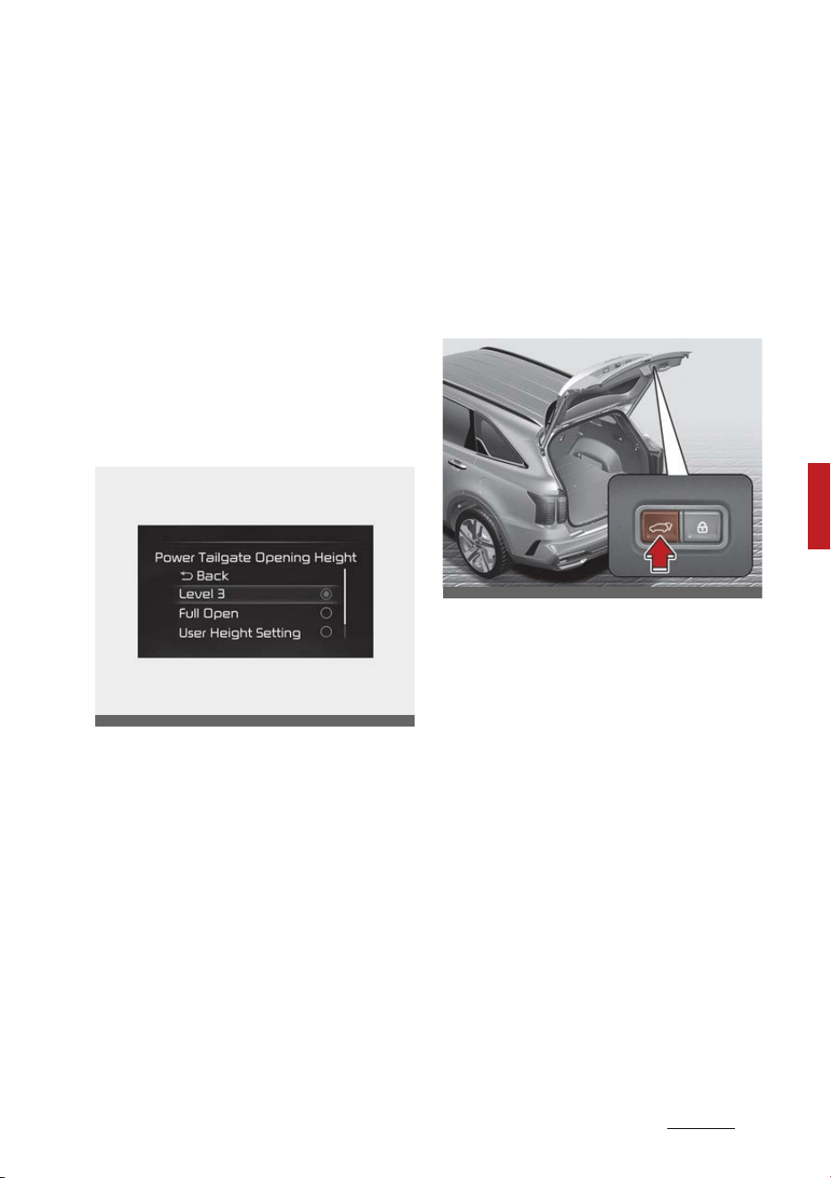
37
5
5
Features of your vehicle Power liftgate
䳜 If power liftgate function turns
off, you can not adjust the power
liftgate speed.
䳜 Initial speed of Power liftgate is
set as "Fast".
For more details, refer to"LCD dis
-
play" on page 5-90.
Power tailgate opening height (if
equipped)
The driver may set the height of a
fully opened tailgate by following
the below instruction.
The tailgate opening height can be
adjusted within the instrument
cluster settings or the infotainment
system.
To adjust the power tailgate open
-
ing height, go to 'User Settings →
Door → Power Tailgate Opening
Height → Level 1/Level 2/Level 3/
Full Open/User Height Setting' to
adjust the vehicle's tailgate height.
If your vehicle is equipped with an
infotainment system, you can learn
how to setup on the website via QR
code in the infotainment quick ref
-
erence guide.
Power tailgate opening height user
setting (if equipped)
The driver may set the height of a
fully opened tailgate by following
the below instruction.
The tailgate opening height can be
adjusted within the infotainment
system.
Go to "User Settings" → "Door" →
"Power Tailgate Opening Height" →
User Height Setting" in order to
adjust your vehicle's tailgate height.
1. Adjust the tailgate to the pre
-
ferred height.
2. Press the power tailgate close
button for approximately 3 sec
-
onds
3. After the beep sound appears, the
setup is finished
OMQ4050215L
OMQ4H051031
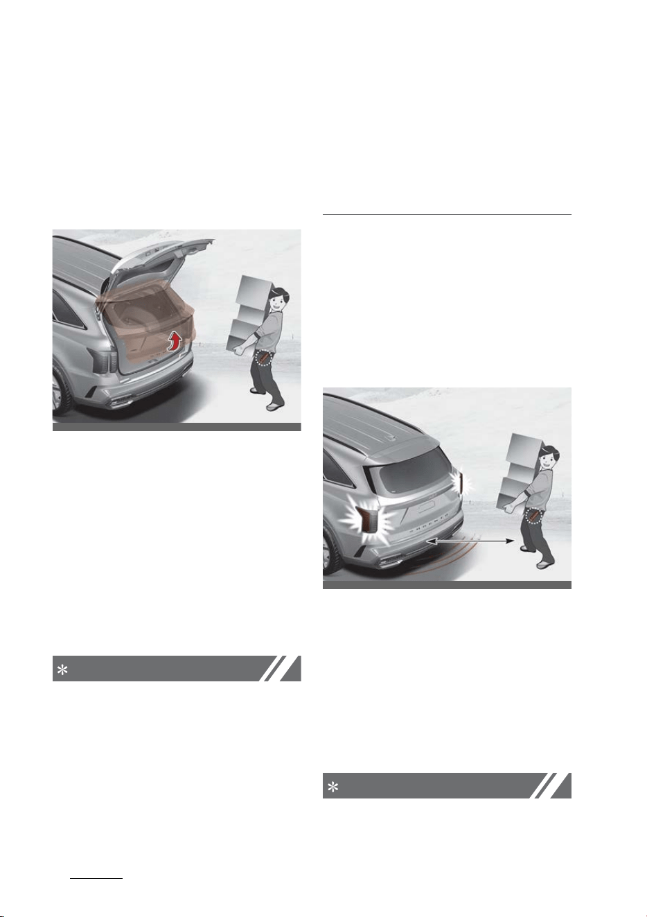
Features of your vehicle
385
Smart Liftgate with Auto Open
Smart Liftgate with Auto Open
(if equipped)
On a vehicle equipped with a smart
key, the liftgate can be opened
using the Smart Liftgate with Auto
Open system.
How to use the Smart Liftgate with
Auto Open
The liftgate can be opened with no-
touch activation satisfying all the
conditions below.
䳜 After 15 seconds when all doors
are closed and locked
䳜 Positioned in the detecting area
for more than 3 seconds.
NOTICE
The Smart Liftgate with Auto Open
does not operate when:
䳜 The smart key is detected within
15 seconds after the doors are
closed and locked, and is continu
-
ously detected.
䳜 The smart key is detected within
15 seconds after the doors are
closed and locked, and 60 in (1.5
m) from the front door handles.
(for vehicles equipped with Wel
-
come Light)
䳜 A door is not locked or closed.
䳜 The smart key is in the vehicle.
1. Setting
To activate the Smart Liftgate
with Auto Open, go to User Set
-
tings Mode and select Smart Lift
-
gate on the LCD display.
For more details, refer to "LCD
display" on page 5-90.
2. Detect and Alert
If you are positioned in the
detecting area (20~40 in [50~100
cm] behind the vehicle) carrying a
smart key, the hazard warning
lights will blink and chime will
sound to alert you the smart key
has been detected and the lift
-
gate will open.
NOTICE
Do not approach the detecting area
if you do not want the liftgate to
OMQ4AH041011
OMQ4AH041013
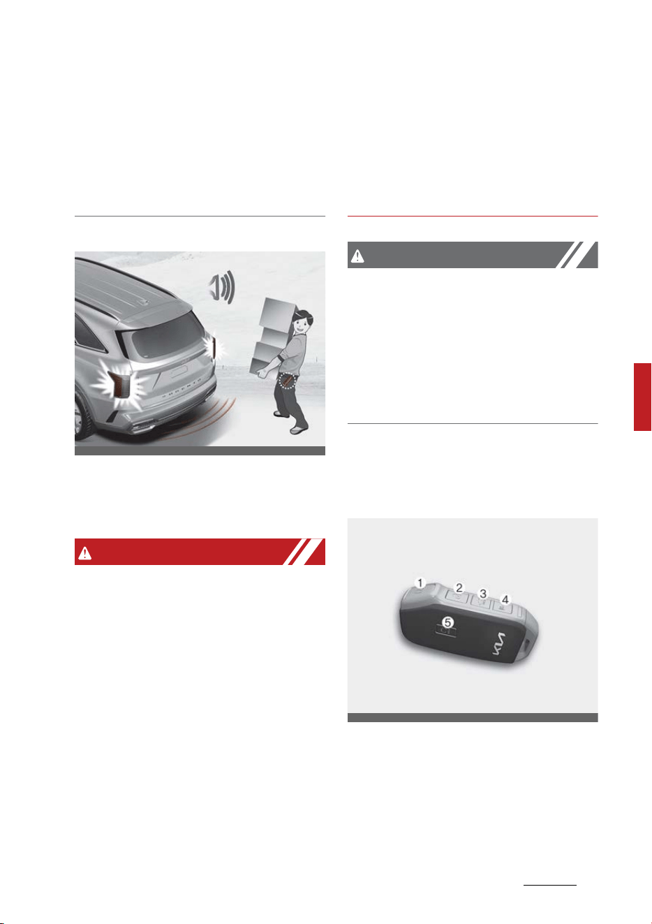
39
5
5
Features of your vehicle Smart Liftgate with Auto Open
open. If you have unintentionally
entered the detecting area and the
hazard warning lights and chime
starts to operate, leave the detect
-
ing area with the smart key. The
liftgate will stay closed.
3. Automatic opening
The hazard warning lights will
blink and chime will sound 6 times
and then the liftgate will open.
WARNING
䳜 Make sure you close the liftgate
before driving your vehicle.
䳜 Make sure there are no people or
objects around the liftgate before
opening or closing the liftgate.
䳜 Make sure objects in the liftgate
do not come out when opening
the liftgate on a slope. It may
cause serious injury.
䳜 Make sure to deactivate the
Smart Liftgate with Auto Open
when washing your vehicle. Oth
-
erwise, the liftgate may open
inadvertently.
䳜 The key should be kept out of
reach of children. Children may
inadvertently open the Smart
Liftgate with Auto Open while
playing around the rear area of
the vehicle.
CAUTION
Liftgate lift
Make certain that you close the lift
-
gate before driving your vehicle.
Possible damage may occur to the
liftgate gas lifters and attached
hardware if the liftgate is not closed
prior to driving.
How to deactivate the Smart Lift
-
gate with Auto Open function using
the smart key
1. Door lock
2. Door unlock
3. Liftgate open
4. Panic button
5. Remote start
OMQ4AH041014
OMQ4041584
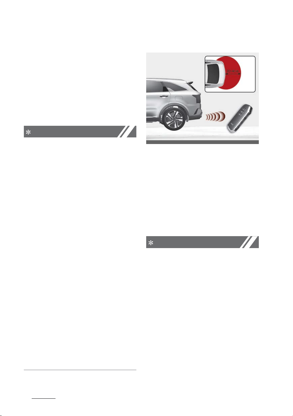
Features of your vehicle
405
Smart Liftgate with Auto Open
If you press any button of the smart
key during the Detect and Alert
stage, the Smart Liftgate with Auto
Open function will be deactivated.
Make sure to be aware of how to
deactivate the Smart Liftgate with
Auto Open function for emergency
situations.
NOTICE
䳜 If you press the door unlock but
-
ton (2), the Smart Liftgate with
Auto Open function will be deacti
-
vated temporarily. But, if you do
not open any door for 30 seconds,
the Smart Liftgate with Auto
Open function will be activated
again.
䳜 If you press the liftgate open but
-
ton (3) for more than 1 second,
the liftgate opens.
䳜 If you press the door lock button
(1) or liftgate open button (3)
when the Smart Liftgate with
Auto Open function is not in the
Detect and Alert stage, the Smart
Liftgate with Auto Open function
will not be deactivated.
䳜 In case you have deactivated the
Smart Liftgate with Auto Open
function by pressing the smart
key button and opened a door, the
Smart Liftgate with Auto Open
function can be activated again by
closing and locking all doors.
Detecting area
䳜 The Smart Liftgate with Auto
Open operates with a welcome
alert if the smart key is detected
within 20~40 in (50~100 cm) from
the liftgate.
䳜 The alert stops at once if the
smart key is positioned outside
the detecting area during the
Detect and Alert stage.
NOTICE
䳜 The Smart Liftgate with Auto
Open function will not work if any
of the following occurs:
- The smart key is close to a
radio transmitter such as a
radio station or an airport
which can interfere with normal
operation of the transmitter.
- The smart key is near a mobile
two way radio system or a cel
-
lular phone.
- Another vehicle's smart key is
being operated close to your
vehicle.
OMQ4AH041015

41
5
5
Features of your vehicle Smart Liftgate with Auto Open
䳜 The detecting range may
decrease or increase when :
- One side of the tire is raised to
replace a tire or to inspect the
vehicle.
- The vehicle is slantingly parked
on a slope or unpaved road, etc.
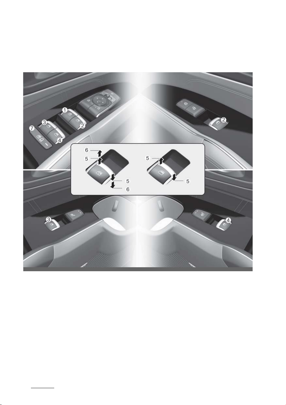
Features of your vehicle
425
Windows
Windows
The doors of this vehicle are equipped with power windows that can be
operated by a switch.
1. Driver's door power window switch
2. Front passenger's door power window switch
3. Rear door (left) power window switch
4. Rear door (right) power window switch
5. Window opening and closing
6. Automatic power window up*/down*
7. Power window lock switch
*: if equipped
OMQ4AH040016

43
5
5
Features of your vehicle Windows
NOTICE
In cold and wet climates, power win
-
dows may not work properly due to
freezing conditions.
The ENGINE START/STOP button
must be in the ON position for
power windows to operate.
Each door has a power window
switch that controls the door's win
-
dow. The driver has a power window
lock button which can block the
operation of rear passenger win
-
dows. The power windows can be
operated for approximately 3 min
-
utes after ENGINE START/STOP
button turned to the ACC or LOCK
position. However, if the front doors
are opened, the power windows
cannot be operated even within the
3 minutes period.
The driver's door has a master
power window switch that controls
all the windows in the vehicle.
If the window cannot be closed
because it is blocked by objects,
remove the objects and close the
window.
NOTICE
While driving with the rear windows
down or with the sunroof (if
equipped) in an open (or partially
open position), your vehicle may
demonstrate a wind buffeting or
pulsation noise. This noise is a nor
-
mal occurrence and can be reduced
or eliminated by taking the following
actions. If the noise occurs with one
or both of the rear windows down,
partially lower both front windows
approximately 1 inch (2.5 cm) If you
experience the noise with the sun
-
roof open, slightly reduce the size of
the sunroof opening.
CAUTION
Do not install any accessories in the
vehicle that extend into the open
window area. Such objects will
impact the proper function of the
Automatic reversal "jam protection"
feature.
NOTICE
If you press the one-touch window
button for micro adjustment, the
glass will go down to a specific loca
-
tion to improve your convenience.
Window opening and closing
You can open and close windows
using the power window switch.
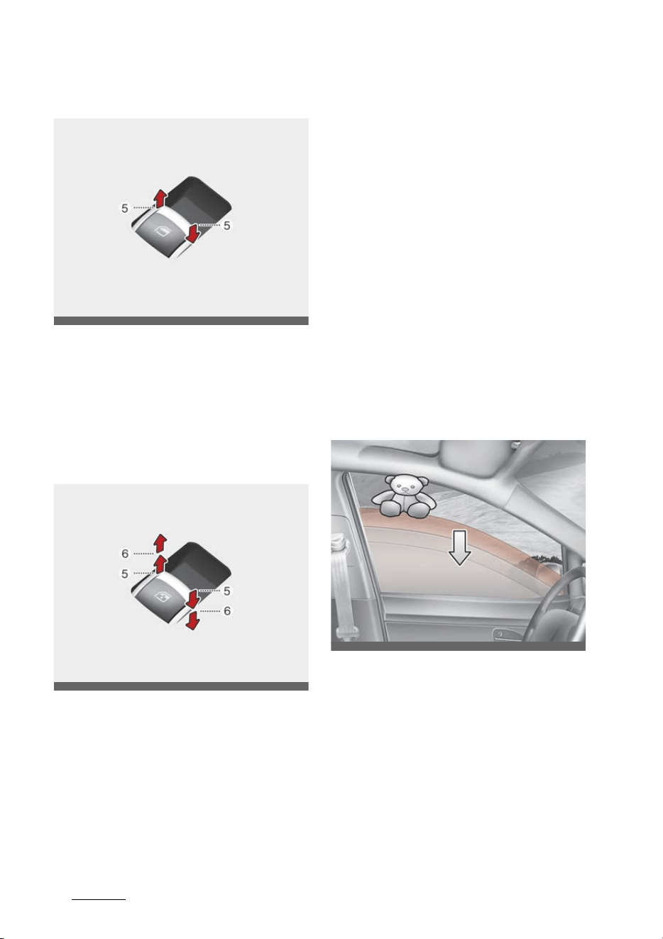
Features of your vehicle
445
Windows
Type A (if equipped)
To open or close a window, press
down or pull up the front portion of
the corresponding switch to the
first detent position (5).
Type B - Auto up/down window (if
equipped)
Pressing or pulling up the power
window switch momentarily to the
second detent position (6) com
-
pletely lowers or raises the window
even when the switch is released. To
stop the window at the desired
position while the window is in oper
-
ation, pull up or press down and
release the switch.
To reset the power windows
If the power window does not oper
-
ate normally, the automatic power
window system must be reset as
follows:
1. Turn the ENGINE START/STOP
button to the ON position.
2. Close the window and continue
pulling up the power window
switch for at least 1 second after
the window is completely closed.
Automatic reversal (if equipped)
If the upward movement of the
window is blocked by an object or
part of the body, the window will
detect the resistance and will stop
upward movement. The window will
then lower approximately 11.8
inches (30 cm) to allow the object to
be cleared.
If the window detects the resistance
while the power window switch is
OMQ4040444
OMQ4040445
ODEEV068020NR
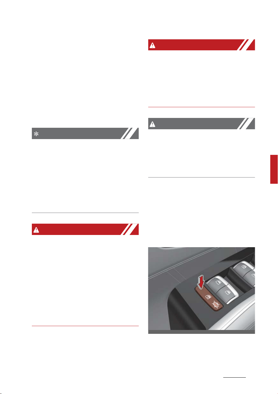
45
5
5
Features of your vehicle Windows
pulled up continuously, the window
will stop upward movement then
lower approximately 1 inch (2.5 cm).
And if the power window switch is
pulled up continuously again within
5 seconds after the window is low
-
ered by the automatic window
reversal feature, the automatic win
-
dow reversal will not operate.
NOTICE
The automatic reverse feature for
the window is only active when the
"auto up" feature is used by fully
pulling up the switch. The automatic
reverse feature will not operate if
the window is raised using the half
-
way position on the power window
switch.
WARNING
Always check for obstructions
before raising any window to avoid
injuries or vehicle damage. If an
object less than 0.16 of an inch (4
mm) in diameter is caught between
the window glass and the upper
window channel, the automatic
reverse window may not detect the
resistance and will not stop and
reverse direction.
WARNING
The automatic reverse feature
doesn't activate while resetting the
power window system. Make sure
body parts or other objects are
safely out of the way before closing
the windows to avoid injuries.
CAUTION
Do not install any accessories in the
vehicle that extend into the open
window area. Such objects could
prevent the automatic reverse fea
-
ture from functioning.
Power window lock button
The driver can disable the power
window switches on the rear pas
-
sengers' doors by pressing the
power window lock button to the
lock position (pressed).
When the power window lock button
is pressed:
OMQ4AH040017

Features of your vehicle
465
Windows
䳜 The driver's master control can
operate all passengers' power
windows.
䳜 The front passenger's control can
operate the front passenger's
power window.
䳜 The rear passengers' control can
-
not operate the rear passenger's
power window.
* If the power window lock switch is
operated (indicator turns on), rear
passenger cannot open the rear
door (if equipped with the Elec
-
tronic Child Safety Lock System).
For more details, refer to "Elec
-
tronic child safety lock system (if
equipped)" on page 5-22.
CAUTION
䳜 To prevent possible damage to
the power window system, do not
open or close two windows or
more at the same time. This will
also ensure the longevity of the
fuse.
䳜 Never try to operate the main
switch on the driver's door and
the individual door window switch
in opposite directions at the same
time. If this is done, the window
will stop and cannot be opened or
closed.
WARNING
Windows
䳜 NEVER leave the keys in your
vehicle with unsupervised chil
-
dren, when the engine is running.
䳜 NEVER leave any child unattended
in the vehicle. Even very young
children may inadvertently cause
the vehicle to move, entangle
themselves in the windows, or
otherwise injure themselves or
others.
䳜 Always double check to make sure
all arms, hands, head and other
obstructions are safely out of the
way before closing a window.
䳜 Do not allow children play with the
power windows. Keep the driver's
door power window lock button in
the LOCK position (pressed). SERI
-
OUS INJURY can result from unin
-
tentional window operation by
the child.
䳜 Do not extend heads or any limbs
outside the window while the
vehicle is in motion.
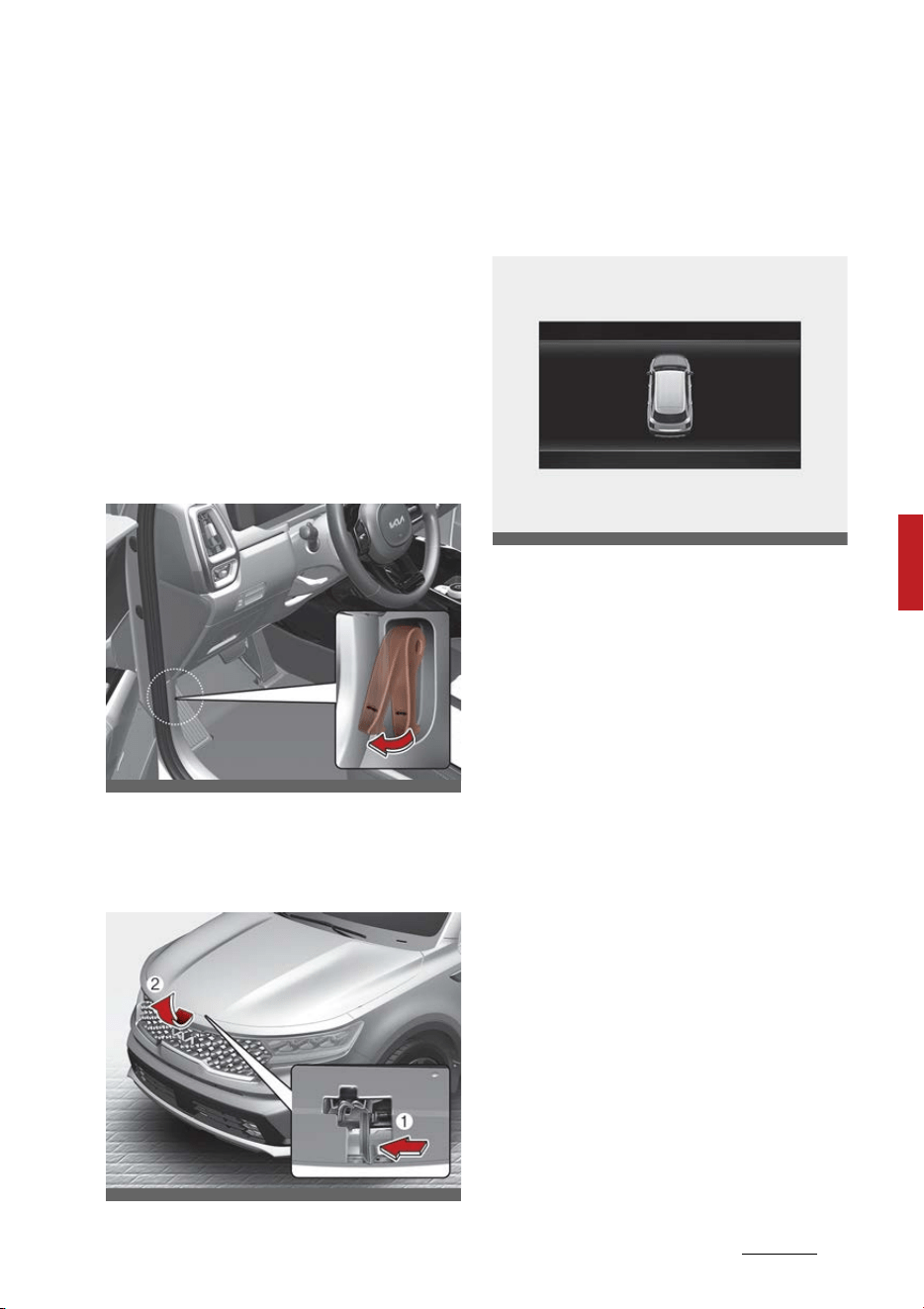
47
5
5
Features of your vehicle Hood
Hood
The hood serves as a cover for the
engine compartment.
Open the hood if maintenance work
needs to be performed in the engine
compartment or if you need to look
at the compartment.
Opening the hood
1. Pull the release lever to unlatch
the hood. The hood should pop
open slightly.
2. Go to the front of the vehicle,
raise the hood slightly, push the
secondary latch (1) to the left and
lift the hood (2).
Hood open warning
The hood warning message will
appear on the LCD display when
hood is open.
The warning chime will operate
when the vehicle is being driven at
or above 2 mph (3 km/h) with the
hood open.
Closing the hood
1. Before closing the hood, check the
following:
䳜 All filler caps in the engine com
-
partment must be correctly
installed.
䳜 Gloves, rags or any other com
-
bustible material must be
removed from the engine com
-
partment.
2. Lower the hood until it is about 30
cm above the closed position and
let it drop. Make sure that it locks
into place.
3. Check that the hood has engaged
properly.
䳜 If the hood can be raise slightly,
it is not properly engaged.
OMQ4041018
OMQ4041446
OMQ4040110
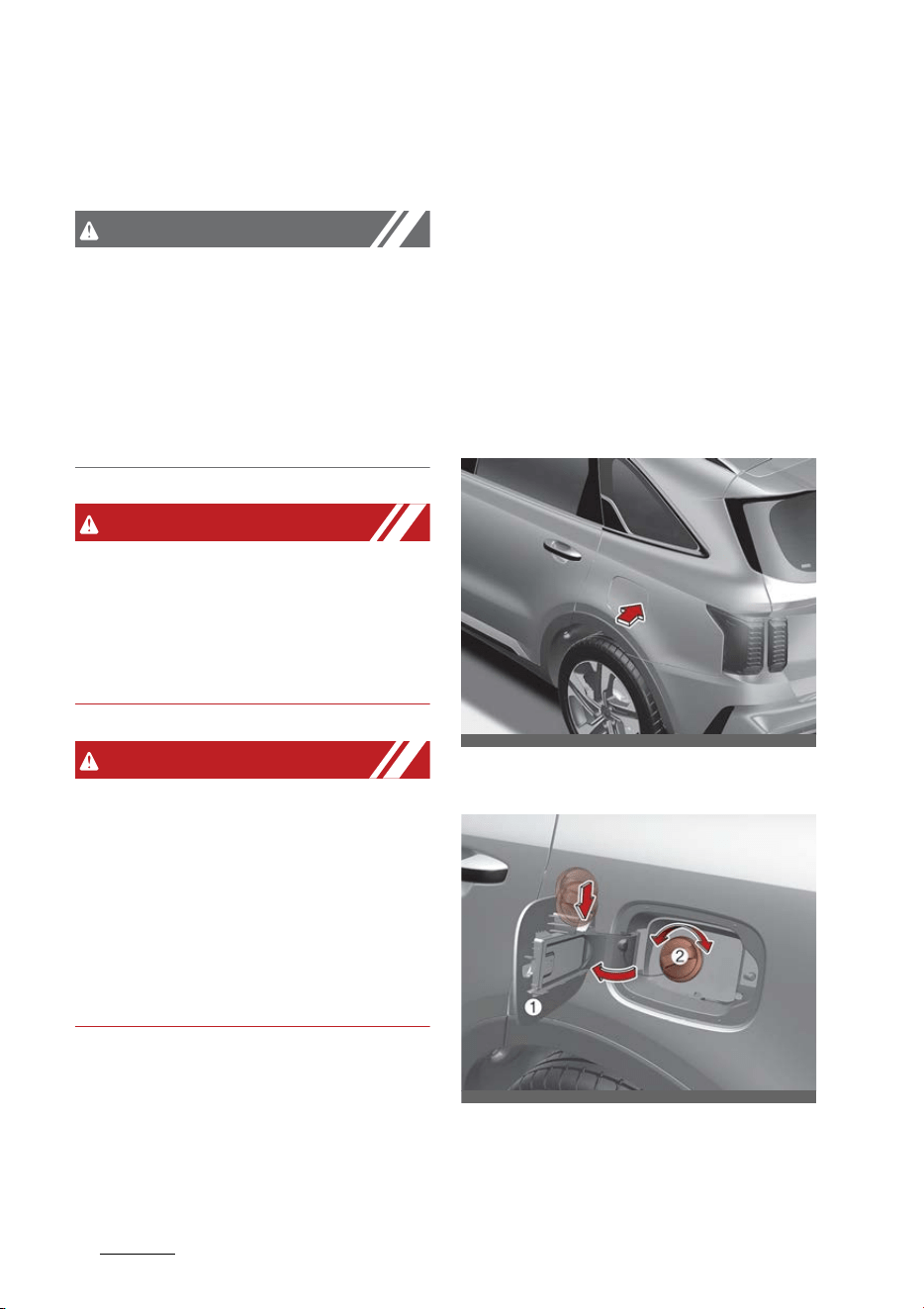
Features of your vehicle
485
Fuel filler door
䳜 Open it again and close it with a
little more force.
CAUTION
Hood obstruction
Before closing the hood, ensure that
all obstructions are removed from
the hood opening. Closing the hood
with an obstruction present in the
hood opening may result in severe
personal injury or properly damage.
WARNING
Fire risk
Do not leave gloves, rags or any
other combustible material in the
motor compartment. Doing so may
cause a heat-induced fire.
WARNING
Unsecured hood
Always double check to be sure that
the hood is firmly latched before
driving away. If it is not latched, the
hood could fly open while the vehicle
is being driven, causing a total loss
of visibility, which may result in an
accident.
Fuel filler door
The vehicle's fuel filler door must be
opened and closed by hand from
outside the vehicle.
Opening the fuel filler door (hybrid
vehicle)
1. Turn the engine off.
2. Ensure the all doors are unlocked.
3. Press the rear center edge of the
fuel filler door.
4. Pull the fuel filler door (1) out to
fully open.
5. To remove the fuel tank cap (2),
turn it counterclockwise. You may
OMQ4AH040562
OMQ4040023
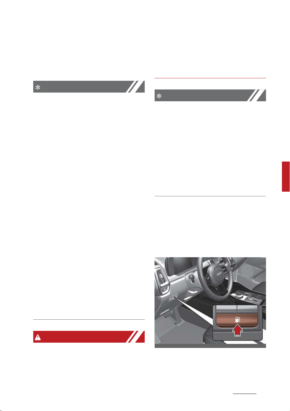
49
5
5
Features of your vehicle Fuel filler door
hear a hissing noise as the pres
-
sure inside the tank equalizes.
6. Place the cap on the fuel filler
door.
NOTICE
The fuel filler door will unlock when
Driver's door is unlocked.
To unlock fuel filler door:
䳜 Press the unlock button on your
smart key
䳜 Press the Central Door unlock
button on armrest trim of driver䳓s
door
䳜 Pull the driver䳓s inside door handle
outward
The fuel filler door will lock when all
doors are locked.
To lock fuel filler door:
䳜 Press the lock button on your
smart key
䳜 Press the Central Door lock but
-
ton on armrest trim of driver䳓s
door
* All doors will automatically lock
after the vehicle speed exceeds
9.3 mph (15 km/h).
Fuel door is also locked when vehicle
speed exceeds 9.3 mph (15 km/h).
WARNING
Before refueling, be sure to check
what type of fuel is used for your
vehicle.
If you put diesel fuel into a gasoline-
powered vehicle, it may affect the
fuel system and cause serious dam
-
age to the vehicle.
NOTICE
If the fuel filler door does not open
because ice has formed around it,
tap lightly or push on the door to
break the ice and release the door.
Do not pry on the door. If necessary,
spray around the door with an
approved de-icer fluid (do not use
radiator anti-freeze) or move the
vehicle to a warm place and allow
the ice to melt.
Opening the fuel filler door (Plug-in
hybrid vehicle)
1. Stop the engine. To open the fuel
filler door, push the fuel filler door
opener button.
2. Wait until the fuel tank is depres
-
surized. The message is dis
-
played when the fuel filler door
OMQ4PH051386L
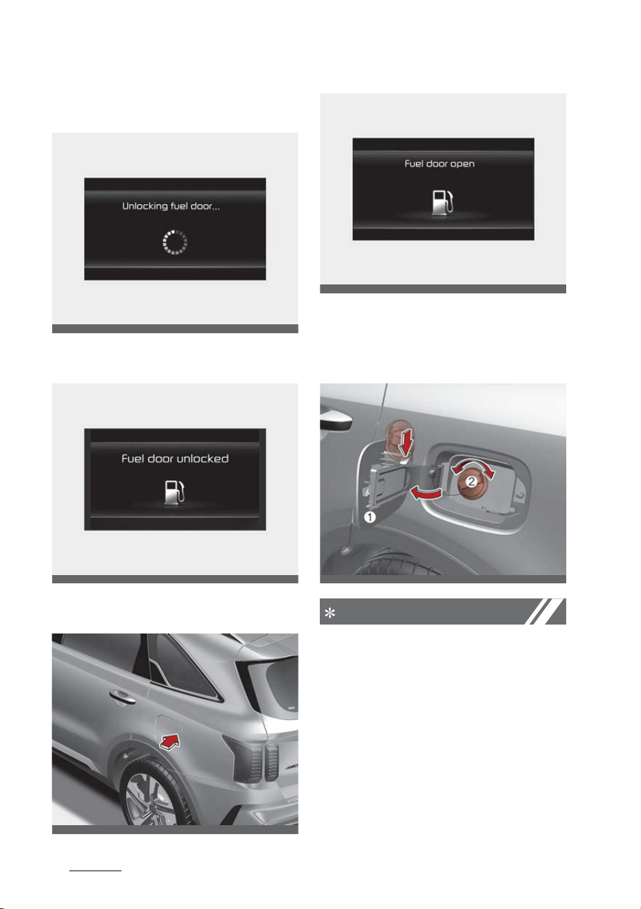
Features of your vehicle
505
Fuel filler door
unlocks after the fuel tank is
depressurized.
3. The fuel door is unlocked when
the message is displayed.
4. Press the rear center edge of the
fuel filler door.
5. Pull open the fuel filler door (1).
To remove the cap, turn the fuel
filler cap (2) counterclockwise.
Refuel as needed.
NOTICE
䳜 It may take up to 20 seconds to
unlock fuel filler door.
䳜 If the fuel filler door does not
open because ice has formed
around it, tap lightly or push on
the door to break the ice and
release the door.
䳜 Do not pry on the door. If neces
-
sary, spray around the door with
an approved de-icer fluid (do not
OMQ4PH050389L
OMQ4PH050383L
OMQ4H040016
OMQ4PH050362L
OMQ4040023

51
5
5
Features of your vehicle Fuel filler door
use radiator anti-freeze) or move
the vehicle to a warm place and
allow the ice to melt.
WARNING
Before refueling, be sure to check
what type of fuel is used for your
vehicle. If you put diesel fuel into a
gasoline-powered vehicle or gaso
-
line into a diesel-powered vehicle, it
may affect the fuel system and
cause serious damage to the vehicle.
NOTICE
䳜 Add fuel into the fuel tank within
20 minutes after opening the fuel
filler door. After 20 minutes, the
fuel tank may shut off, causing
fuel to overflow. In this case, re-
press the fuel filler door opening
button.
䳜 Do not leave the fuel filler door
opened for an extended period of
time. It may discharge the bat
-
tery.
䳜 Close the fuel filler door after
fueling the vehicle. If you start the
vehicle with the fuel filler door
opened, "Check fuel door" mes
-
sage illuminates on the LCD dis
-
play.
䳜 Avoid refueling the vehicle while
charging the (high-voltage) hybrid
battery. It may cause a fire or an
explosion due to static electricity.
WARNING
For Plug-in Hybrid
Avoid refueling the vehicle while
charging the (high-voltage) hybrid
battery. It may cause a fire or an
explosion due to static electricity.
Closing the fuel filler door
1. To install the fuel tank cap, turn it
clockwise until it "Clicks".
2. Close the fuel filler door by press
-
ing rear center edge of the fuel
filler door.
NOTICE
Make the vehicle door to LOCK posi
-
tion when the fuel filler door is com
-
pletely closed in order to lock the
fuel filler door.
If the fuel filler door is not com
-
pletely closed, the fuel filler door will
not be locked.
WARNING
Refueling
Always remove the fuel cap care
-
fully and slowly. If the cap is venting
fuel or if you hear a hissing sound,
wait until the condition stops before
completely removing the cap.
If pressurized fuel sprays out, it can
cover your clothes or skin and sub
-
ject you to the risk of fire and burns.

Features of your vehicle
525
Fuel filler door
NOTICE
When refueling on unlevel ground,
the fuel gauge may not point to the
F position. It is not a malfunction. If
you move your vehicle to a level
ground, the fuel gauge will move to
the full position.
NOTICE
Tighten the cap until it clicks one
time, otherwise, the engine warn
-
ing indicator light will illuminate.
CAUTION
Keep the door into LOCK position
when the vehicle is being washed
(i.e. high pressure washer, auto
-
matic car washer, etc.)
WARNING
Always tighten your fuel cap before
you leave the fuel station. Failure to
securely install your fuel cap can
lead to fuel spillage in an accident
and increase fire risk.
WARNING
Fire/explosion risk
Read and follow all warnings posted
at the gas station facility. Failure to
follow all warnings will result in
severe personal injury, severe burns
or death due to fire or explosion.
WARNING
Static electricity
䳜 Before touching the fuel nozzle,
you should eliminate potentially
dangerous static electricity dis
-
charge by touching another metal
part of the vehicle, a safe distance
away from the fuel filler neck,
nozzle, or other gas source.
䳜 Do not get back into a vehicle
once you have begun refueling
since you can generate static
electricity by touching, rubbing or
sliding against any item or fabric
(polyester, satin, nylon, etc.)
capable of producing static elec
-
tricity. Static electricity discharge
can ignite fuel vapors resulting in
rapid burning. If you must reenter
the vehicle, you should once again
eliminate potentially dangerous
static electricity discharge by
touching a metal part of the vehi
-
cle, away from the fuel filler neck,
nozzle or other gasoline source.
WARNING
Portable fuel container
When using an approved portable
fuel container, be sure to place the
container on the ground prior to
refueling. Static electricity discharge

53
5
5
Features of your vehicle Fuel filler door
from the container can ignite fuel
vapors causing a fire. Once refueling
has begun, contact with the vehicle
should be maintained until the filling
is complete. Use only approved por
-
table plastic fuel containers
designed to carry and store gaso
-
line.
WARNING
Cell phone fires
Do not use cellular phones while
refueling. Electric current and/or
electronic interference from cellular
phones can potentially ignite fuel
vapors causing a fire.
WARNING
Refueling & Vehicle fires
When refueling, always shut the
engine off. Sparks produced by elec
-
trical components related to the
engine can ignite fuel vapors causing
a fire. Once refueling is complete,
check to make sure the filler cap and
filler door are securely closed,
before starting the engine.
WARNING
Smoking
DO NOT use matches or a lighter
and DO NOT SMOKE or leave a lit
cigarette in your vehicle while at a
gas station especially during refuel
-
ing. Automotive fuel is highly flam
-
mable and can, when ignited, result
in fire.
Make sure to refuel your vehicle
according to "Fuel requirements" on
page 2-2.
If the fuel filler cap requires replace
-
ment, use only a genuine Kia cap or
the equivalent specified for your
vehicle. An incorrect fuel filler cap
can result in a serious malfunction
of the fuel system or emission con
-
trol system.
CAUTION
Exterior paint
Do not spill fuel on the exterior sur
-
faces of the vehicle. Any type of fuel
spilled on painted surfaces may
damage the paint.
WARNING
䳜 Do not allow anyone that has not
discharged static electricity from
their body to come close to an
open fuel tank.
䳜 Do not inhale vaporized fuel.
WARNING
Risk of injury from fuel
Fuels are poisonous and harmful to
your health.

Features of your vehicle
545
Fuel filler door
䳜 Fuel contains substances that are
harmful if inhaled.
䳜 Do not swallow fuel or let it come
into contact with skin, eyes or
clothing.
䳜 Do not inhale fuel vapors.
䳜 Keep children away from fuel.
If you or other people come into
contact with fuel, observe the fol
-
lowing:
䳜 Immediately rinse fuel off your
skin with soap and water.
䳜 If fuel comes into contact with
your eyes, immediately rinse
them thoroughly with clean
water. Seek medical attention
immediately.
䳜 If you swallow fuel, seek medical
attention immediately. Do not
induce vomiting.
䳜 Change immediately out of cloth
-
ing that has come into contact
with fuel.
NOTICE
Damage caused by the wrong fuel
Fuel that does not conform to the
required quality can lead to
increased wear as well as damage to
the engine and exhaust system.
Only use the fuel recommended.
NOTICE
Damage caused by the wrong fuel
Vehicles with a gasoline engine:
Even small amounts of the wrong
fuel could result in damage to the
fuel system, the engine and the
emission control system.
NOTICE
Do not use diesel to refuel vehicles
with a gasoline engine.
NOTICE
Do not press the ENGINE START/
STOP button if you accidentally
refuel with the wrong fuel. Other
-
wise, fuel can enter the fuel system.
Even small amounts of the wrong
fuel could result in damage to the
fuel system and the engine. Have
the system serviced by an autho
-
rized Kia dealer.
NOTICE
Do not overfill the fuel tank
Do not overfill the fuel tank; other
-
wise fuel may spill, causing harm to
the environment and damaging the
vehicle.
WARNING
In case of using EV drive mode for a
certain time without running engine,
EMM (Engine Maintenance Mode)
will automatically activate by the
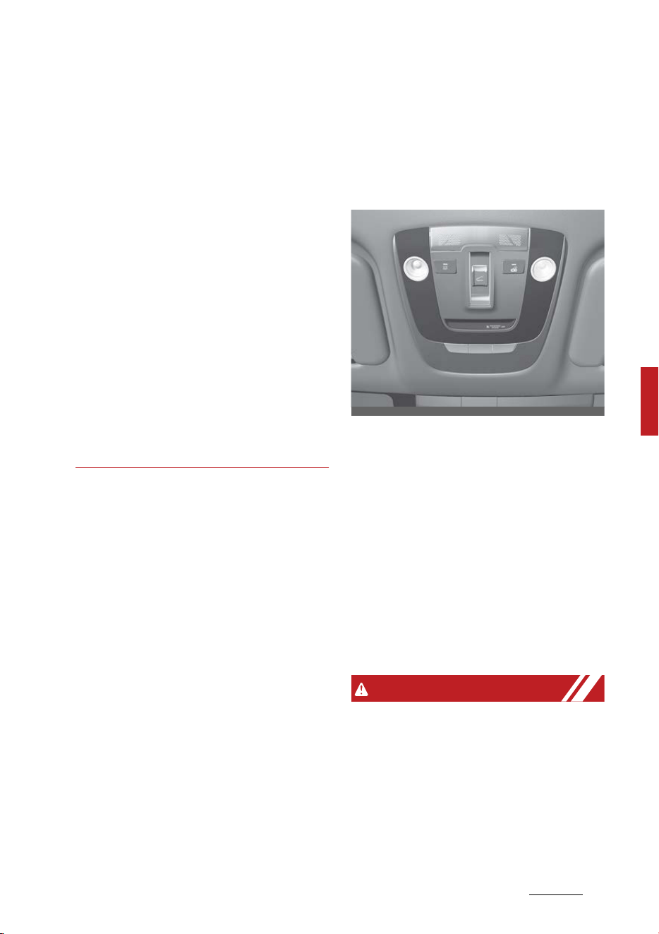
55
5
5
Features of your vehicle Panoramic sunroof
system to protect the fuel system
and the engine.
Therefore, even though if it is possi
-
ble to use EV drive mode with
enough battery power, the engine
may run by the system to protect
fuel system and the engine. If you
leave the fuel without refueling or
using for over 6 months, the
remained fuel in the fuel system
may be deteriorated. From this,
corrosion or blocking problem may
occur.
It is recommended using minimum
40% of remained fuel at least every
6 months by selecting Hybrid (CS)
mode and refuel the vehicle with
new fuel.
Panoramic sunroof (if equipped)
If your vehicle is equipped with a
sunroof, you can slide or tilt your
sunroof with the sunroof switch
located on the overhead console.
The sunroof can only be operated
when the ENGINE START/STOP
button is in the ON or START posi
-
tion.
The sunroof can be operated for
approximately 3 minutes after the
ENGINE START/STOP button is in
the ACC or LOCK/OFF position. How
-
ever, if the front door is open, the
sunroof cannot be operated even
within the 3 minute period.
WARNING
䳜 Never adjust the sunroof or sun
-
shade while driving. This could
result in loss of control and an
accident that may cause injury, or
property damage.
䳜 Do not leave the engine running
and the key in your vehicle with
OMQ4041590N
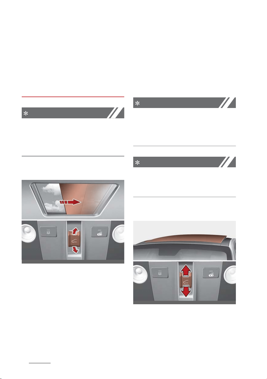
Features of your vehicle
565
Panoramic sunroof
unsupervised children. Unat
-
tended children could operate the
sunroof, which could result in
serious injury.
䳜 Do not sit on the top of the vehi
-
cle. It may cause injury or vehicle
damage.
NOTICE
䳜 Do not operate the sunroof when
roof bars are installed on the
vehicle or when there is luggage
on the roof.
Power sunshade
Use the power sunshade to block
direct sunlight coming through the
sunroof glass.
䳜 Push the sunroof switch rearward
to the first detent position, the
power sunshade automatically
slides open.
䳜 Push the sunroof switch forward
to the first detent position, the
power sunshade automatically
closes. However, if the sunroof
glass is open, the glass will close
first.
To stop the power sunshade at any
point, push the sunroof switch in
any direction.
NOTICE
Do not pull or push the power sun
-
shade by hand as such action may
damage the power sunshade or
cause it to malfunction.
NOTICE
Wrinkles formed on the power sun
-
shade are normal due to material
characteristic.
Tilt open/close
䳜 Push the sunroof switch upward,
the sunroof glass tilts open. How
-
ever, if the power sunshade is
close, the sunshade will open first.
OMQ4041490N
OMQ4PH041491
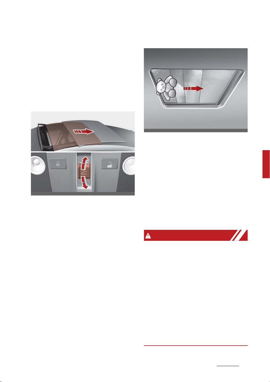
57
5
5
Features of your vehicle Panoramic sunroof
䳜 Push the sunroof switch forward,
the sunroof glass automatically
closes.
To stop the sunroof movement at
any point, push the sunroof switch
in any direction.
Slide open/close
䳜 Push the sunroof switch rearward
to the first detent position, the
sunroof glass opens. However, if
the power sunshade is close, the
power sunshade will open first.
䳜 Push the sunroof switch forward
to the first detent position, the
sunroof glass closes. However, if
the sunroof glass is close, the
power sunshade will close.
䳜 Push the sunroof switch forward
or rearward to the second detent
position, the power sunshade and
sunroof glass operate automati
-
cally (auto slide feature).
To stop the sunroof movement at
any point, push the sunroof
switch in any direction.
Automatic reversal
If the power sunshade or sunroof
glass senses any obstacle while it is
closing automatically, it will reverse
direction then stop at a certain posi
-
tion.
The auto reverse function may not
work if an object thin or soft is
caught between the sliding power
sunshade or sunroof glass and sun
-
roof sash.
WARNING
䳜 Make sure heads, hands, arms or
any other body parts or objects
are out of the way before operat
-
ing the sunroof. Body parts or
objects may get caught causing
injuries or vehicle damage.
䳜 Never deliberately use your body
parts to test the automatic rever
-
sal function. The power sunshade
or sunroof glass may reverse
direction, but there is a risk of
injury.
OMQ4041592N
OCDW049449
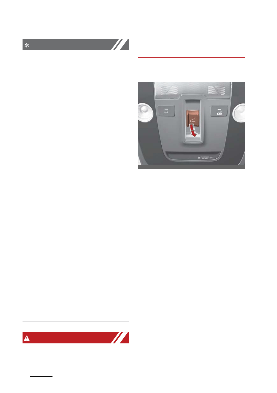
Features of your vehicle
585
Panoramic sunroof
NOTICE
䳜 Do not continue to push the sun
-
roof switch after the sunroof is
fully opened, closed, or tilted.
Damage to the sunroof motor
could occur.
䳜 Continuous operations such as
slide open/close, tilt open/close,
etc. may cause the motor or sun
-
roof system to malfunction.
䳜 Regularly remove any accumu
-
lated dust on the sunroof rail.
䳜 Dust accumulated between the
sunroof and roof panel can make
noise Open the sunroof and
remove dust regularly using a
clean cloth.
䳜 Do not try to open the sunroof
when the temperature is below
freezing or when the sunroof is
covered with snow or ice. The
sunroof may not work properly
and may break if opened by force.
䳜 Do not open or drive with the
sunroof glass open immediately
after rain or washing the vehicle.
Water may wet the interior of the
vehicle.
䳜 Do not extend any luggage out
-
side the sunroof while driving.
Vehicle damage may occur if the
vehicle suddenly stops.
WARNING
Do not extend your head, arms,
body parts or objects outside the
sunroof while driving. Injuries may
occur if the vehicle suddenly stops.
Resetting the sunroof
In some circumstances resetting the
sunroof operation may need to be
performed. Some instances where
resetting the sunroof may be
required include:
䳜 When the 12-volt battery is
either disconnected or discharged
䳜 When the sunroof fuse is replaced
䳜 If the sunroof one-touch AUTO
OPEN/CLOSE operation is not
functioning properly
Sunroof resetting procedure:
1. It is recommended to perform the
reset procedure with the vehicle
engine running. Start the vehicle
in P (Park).
2. Make sure the power sunshade
and sunroof glass are in the fully
closed position. If the power sun
-
shade and sunroof glass are open,
push the switch forward until the
OMQ4041593N
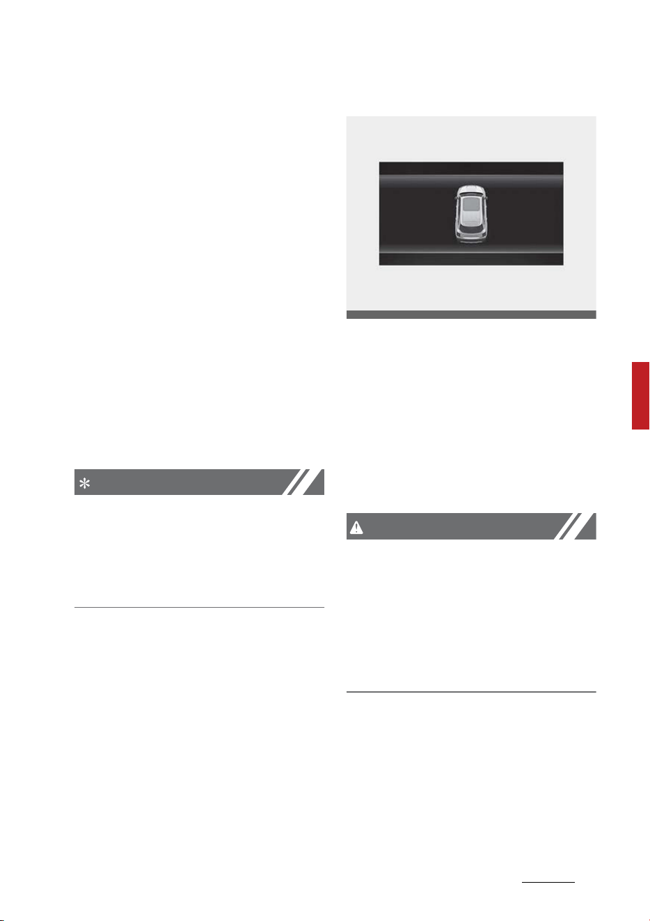
59
5
5
Features of your vehicle Panoramic sunroof
power sunshade and sunroof
glass are fully closed.
3. Release the switch when the
power sunshade and sunroof
glass are fully closed.
4. Push the switch forward until the
power sunshade and sunroof
glass move slightly. Then release
the switch.
5. Once again push and hold the
sunroof switch forward until the
power sunshade and sunroof
glass slide open and close. Do not
release the switch until the oper
-
ation is completed.
If you release the switch during
operation, start the procedure
again from step 2.
NOTICE
If the sunroof does not reset when
the vehicle battery is disconnected
or discharged, or the sunroof fuse is
blown, the sunroof may not operate
normally.
Sunroof open warning
If the driver turns off the engine
when the sunroof is not fully closed,
the warning chime will sound for
several seconds and the sunroof
open warning will appear on the
cluster LCD display.
Close the sunroof securely when
leaving your vehicle.
CAUTION
Make sure the sunroof is closed fully
when leaving your vehicle. If the
sunroof is left open, rain or snow
may wet the interior of the vehicle.
Also, leaving the sunroof open when
the vehicle is unattended may invite
theft.
OMQ4040131

Features of your vehicle
605
Steering wheel
Steering wheel
The steering wheel of this vehicle is
equipped with the Electric Power
Steering (EPS) system.
Electric power steering (EPS)
Power steering uses the motor to
assist you in steering the vehicle.
If the engine is off or if the power
steering system becomes inopera
-
tive, the vehicle may still be steered,
but it will require increased steering
effort.
The EPS is controlled by the power
steering control unit which senses
the steering wheel torque and vehi
-
cle speed to command the motor.
The steering effort becomes
heavier as the vehicle's speed
increases and becomes lighter as
the vehicle's speed decreases for
better control of the steering wheel.
Should you notice any change in the
effort required to steer during nor
-
mal vehicle operation, have the sys
-
tem checked by an authorized Kia
dealer.
NOTICE
The following symptoms may occur
during normal vehicle operation:
䳜 When the ENGINE START/STOP
button is the ON position, the
steering wheel enters normal
operation mode after diagnosing
the Electric Power Steering sys
-
tem (for about 3 seconds).
䳜 A click noise may be heard from
the EPS relay after turning the
ENGINE START/STOP button is
turned to the ON or OFF position.
䳜 If the steering wheel is operated
when the vehicle is not in motion
or driven at a low speed, you may
hear some noise.
䳜 If the Electric Power Steering sys
-
tem does not operate normally,
the warning light will illuminate or
blink on the instrument cluster. If
the power assistance of steering
fails, you will need to use more
force to steer.
䳜 Operating the steering wheel at
lower temperatures may require
more force and accompany noise.
However, when the temperature
increases, it returns to normal.
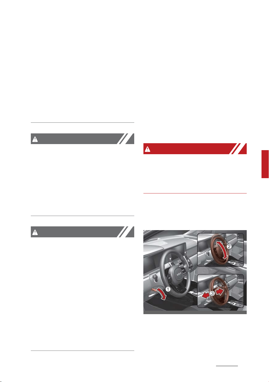
61
5
5
Features of your vehicle Steering wheel
䳜 Take your vehicle to an authorized
Kia dealer and have the vehicle
checked as soon as possible.
䳜 When the charging system warn
-
ing light comes on due to the low
voltage (when the alternator or
battery does not operate nor
-
mally or malfunctions), the steer
-
ing wheel may require increased
steering effort.
CAUTION
When you continuously operate the
steering wheel, the overcurrent
protection device is activated and it
requires more force to operate the
steering wheel. However, this
doesn't indicate a malfunction, and
it works for your safety and will
return to normal after some time.
CAUTION
If the Electric Power Steering (EPS)
system does not work or an error
occurs, the warning light on the
instrument panel may be turned on
or blink and it may require more
force to operate the steering wheel.
In this case, please hold the steering
wheel more tightly than usual and
operate with greater force. And
then immediately pull your vehicle
over to a safe place and have your
vehicle inspected by an authorized
Kia dealer.
Tilt & telescopic steering wheel
A tilt and telescopic steering wheel
allows you to adjust the steering
wheel before you drive. You can also
raise it to give your legs more room
when you exit and enter the vehicle.
The steering wheel should be posi
-
tioned so that it is comfortable for
you to drive, while permitting you to
see the instrument panel warning
lights and gauges.
WARNING
Steering wheel adjustment
Never adjust the angle and height of
the steering wheel while driving. You
may lose steering control.
Adjusting steering wheel angle and
height
OMQ4041028
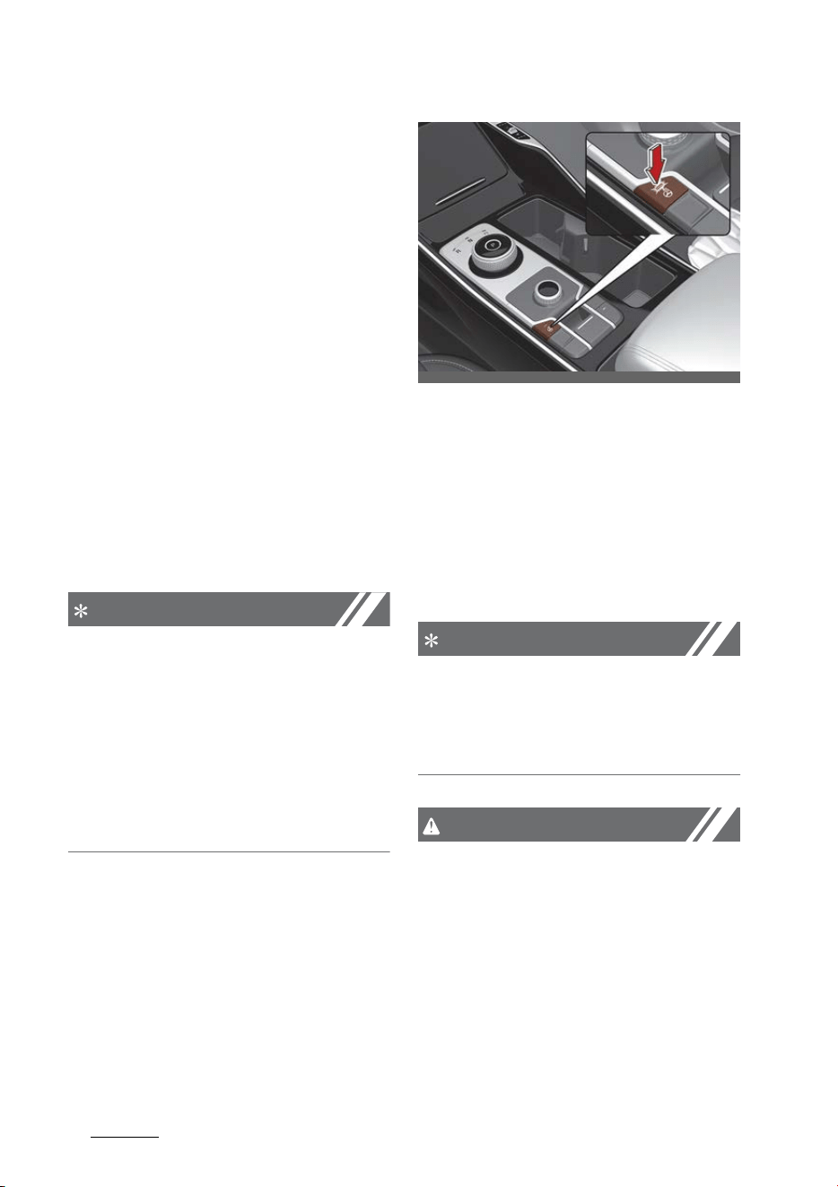
Features of your vehicle
625
Steering wheel
1. To change the steering wheel
angle, pull down the lock release
lever (1).
2. Adjust the steering wheel to the
desired angle (2) and height (3).
Move the steering wheel, so it
points toward your chest, not
toward your face. Make sure you
can see the instrument panel
warning lights and gauges. After
adjusting, pull up the lock.
3. Pull up the lock-release lever to
lock the steering wheel in place.
Push the steering wheel both up
and down to be certain it is locked
in position.
4. Be sure to adjust the steering
wheel to the desired position
before driving.
NOTICE
After adjustment, sometimes the
lock-release lever may not lock the
steering wheel.
It is not a malfunction. This occurs
when two gears engage. In this
case, adjust the steering wheel
again and then lock the steering
wheel.
Heated steering wheel (if equipped)
When the ENGINE START/STOP
button is in the ON position, press
-
ing the heated steering wheel but
-
ton warms the steering wheel. The
indicator on the button will illumi
-
nate.
To turn the heated steering wheel
off, press the button once again.
The indicator on the button will turn
off.
䳜 The heated steering wheel
defaults to the OFF position
whenever the ENGINE START/
STOP button is in the ON position.
NOTICE
The heated steering wheel will turn
off automatically approximately 30
minutes after the heated steering
wheel is turned on.
CAUTION
䳜 Do not install any type of grip
cover for the steering wheel, it
may impair the function of the
heated steering wheel system.
OMQ4AH040029
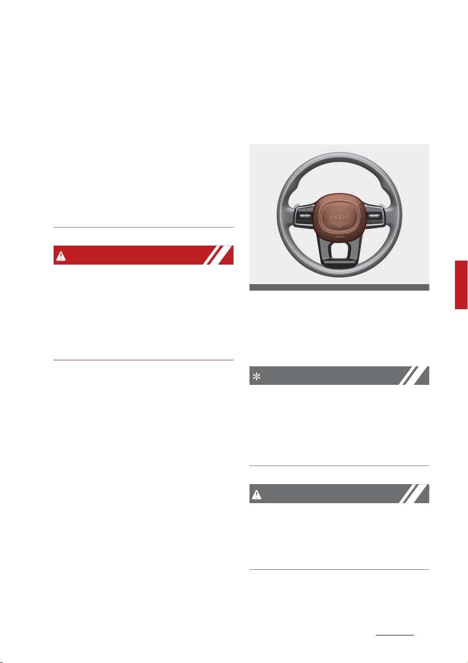
63
5
5
Features of your vehicle Steering wheel
䳜 When cleaning the heated steer
-
ing wheel, do not use an organic
solvent such as paint thinner,
benzene, alcohol and gasoline.
Doing so may damage the surface
of the steering wheel.
䳜 If the surface of the steering
wheel is damaged by a sharp
object, damage to the heated
steering wheel components could
occur.
WARNING
If the steering wheel becomes too
warm, turn the system off. The
heated steering wheel may cause
burns even at low temperatures,
especially if used for long periods of
time.
Horn
To sound the horn, press the area
indicated by the horn symbol on
your steering wheel (see illustra
-
tion).
The horn will operate only when this
area is pressed. Check the horn reg
-
ularly to be sure it operates prop
-
erly.
NOTICE
To sound the horn, press the area
indicated by the horn symbol on
your steering wheel (see illustra
-
tion). The horn will operate only
when this area is pressed.
CAUTION
䳜 Do not strike the horn severely to
operate it, or hit it with your fist.
Do not press on the horn with a
sharp-pointed object.
OMQ4041030
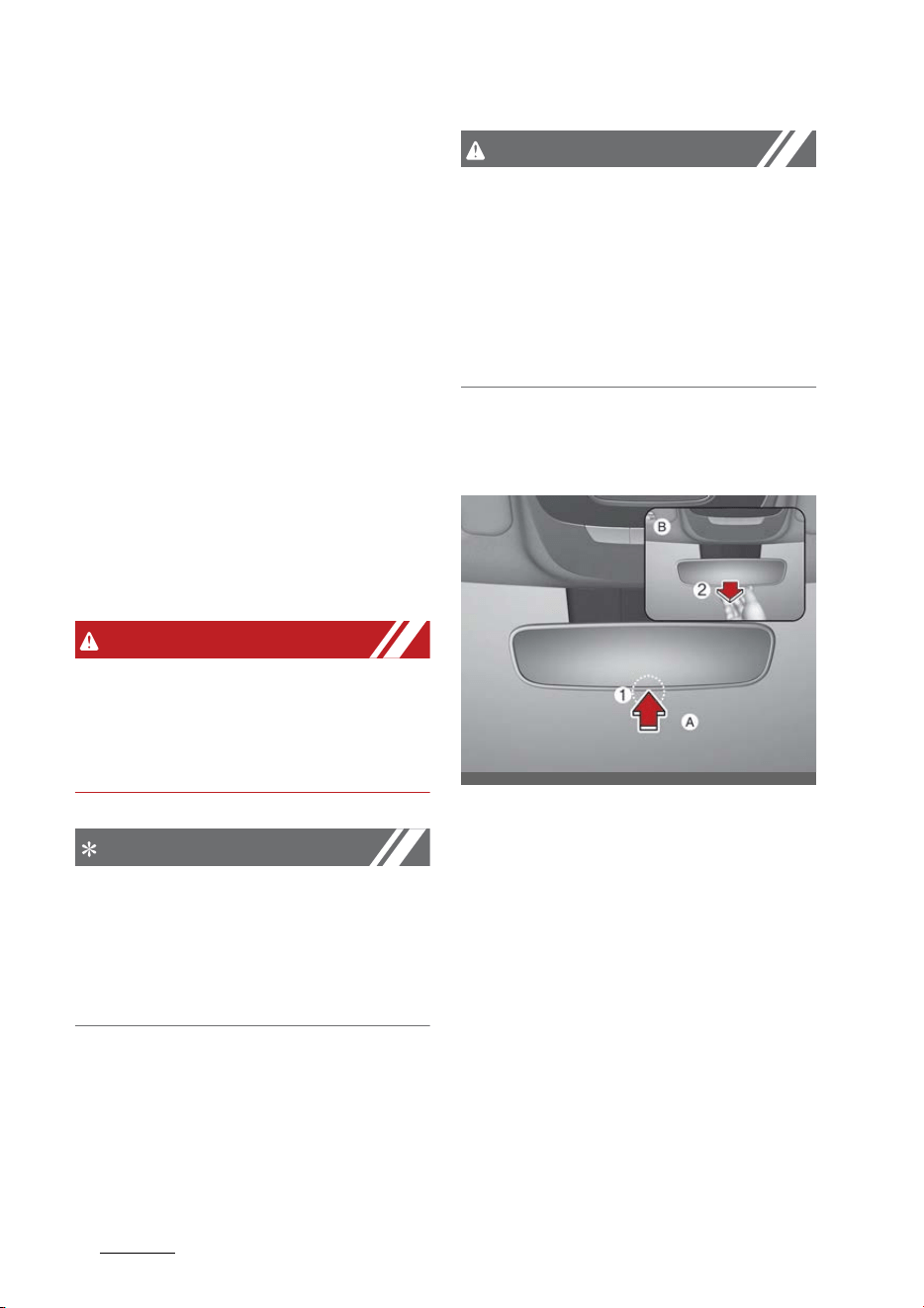
Features of your vehicle
645
Mirrors
Mirrors
This vehicle is equipped with inside
and outside rear view mirrors to
provide views of objects behind the
vehicle.
Inside rear view mirror
Adjust the rear view mirror so that
the center view through the rear
window is seen. Make this adjust
-
ment before you start driving.
Do not place objects in the rear seat
or cargo area which would interfere
with your vision out the rear win
-
dow.
WARNING
Mirror adjustment
Do not adjust the rear view mirror
while the vehicle is moving. This
could result in loss of control.
NOTICE
Do not modify the inside mirror in
any manner, including installing a
wide mirror. Doing so could result in
injury during an accident or deploy
-
ment of the air bag.
CAUTION
Cleaning mirror
When cleaning the mirror, use a
paper towel or similar material
dampened with glass cleaner. Do not
spray glass cleaner directly on the
mirror. It may cause the liquid
cleaner to enter the mirror housing.
Day/night rear view mirror (if
equipped)
(A): Day, (B): Night
Make this adjustment before you
start driving and while the day/night
lever is in the day position (1).
Pull the day/night lever toward you
(2) to reduce the glare from the
headlamps of the vehicles behind
you during night driving.
Remember that you lose some rear
view clarity in the night position.
OMQ4041496N
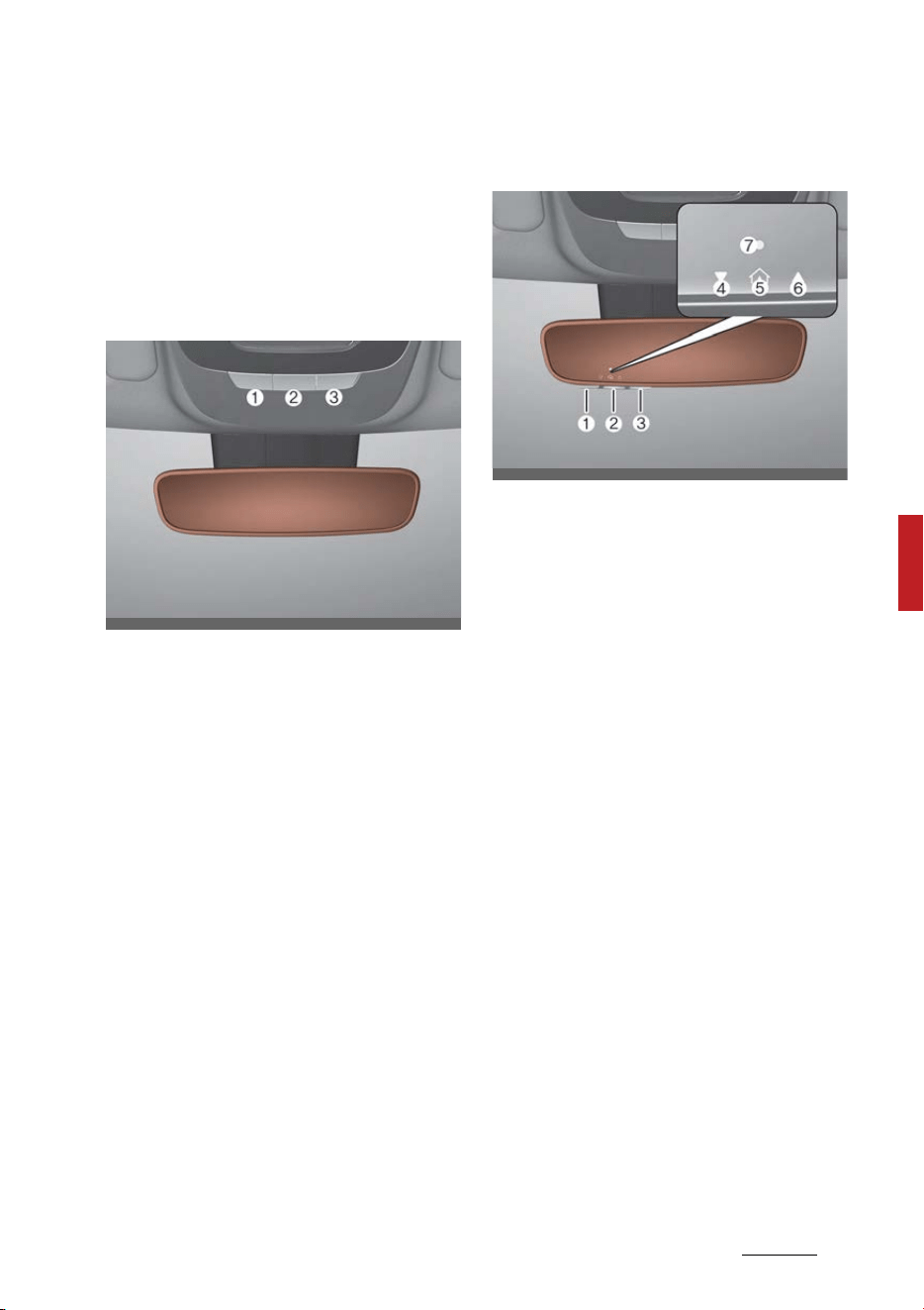
65
5
5
Features of your vehicle Mirrors
Electric Chromic Mirror (ECM) (if
equipped)
The electric rear view mirror auto
-
matically controls the glare from
the headlamps of the vehicles
behind you in nighttime or low light
driving conditions.
For Telematics button function:
1. Virtual assist button
2. UVO (Voice local search) button
3. Roadside assist button
The sensor mounted in the mirror
senses the light level around the
vehicle, and automatically controls
the headlamp glare from the vehi
-
cles behind you.
When the engine is running, the
glare is automatically controlled by
the sensor mounted in the rear view
mirror.
Electric Chromic mirror (ECM) with
HomeLink system (if equipped)
1. HomeLink Channel 1
2. HomeLink Channel 2
3. HomeLink Channel 3
4. Garage Door Opener Status Indi
-
cator: Closing or Closed
5. HomeLink Operation Indicator
6. Garage Door Opener Status Indi
-
cator: Opening or Opened
7. HomeLink User Interface Indicator
Your vehicle may be equipped with a
Gentex Automatic-Dimming Mirror
with an Integrated HomeLink
Wireless Control System.
During nighttime driving, this fea
-
ture will automatically detect and
reduce rear view mirror glare. The
HomeLink Universal Transceiver
allows you to activate your garage
door(s), electric gate, home lighting,
etc.
OMQ4041492N
OMQ4041544N

Features of your vehicle
665
Mirrors
Automatic-Dimming Night Vision
Safety™ (NVS) Mirror (if
equipped)
The NVS Mirror automatically
reduces glare by monitoring light
levels in the front and the rear of
the vehicle. Any objects that
obstruct the light sensor will
degrade the automatic dimming
control feature.
For more information regarding
NVS mirrors and other applica
-
tions, please refer to the Gentex
website: www.gentex.com
Your mirror will automatically dim
upon detecting glare from the vehi
-
cles traveling behind you.
The mirror defaults to the ON posi
-
tion each time the vehicle is started.
Integrated HomeLink Wireless
Control System
The HomeLink Wireless Control
System provides a convenient way
to replace up to three handheld
radio-frequency (RF) transmitters
used to activate compatible devices
such as gate operators, garage door
openers, entry door locks, security
systems, and home lighting.
NOTICE
Considering the Home Security
when the vehicle is parked outside
the garage, the HomeLink will
ONLY work while the vehicle is in the
ACC or ON position.
CAUTION
Before programming HomeLink to a
garage door opener or gate opera
-
tor, make sure that people and
objects are out of the way of the
device to prevent potential harm or
damage. When programming a
garage door opener, it is advised to
park outside of the garage.
Do not use HomeLink with any
garage door opener that lacks
safety stop and reverse features as
required by U.S. federal safety
standards (this includes any garage
door opener model manufactured
before April 1, 1982). A garage door
that cannot detect an object signal
-
ing the door to stop and reverse -
does not meet current U.S. federal
safety standards. For more infor
-
mation, contact HomeLink at
www.homelink.com, or call Home
-
Link customer support at 1-800-
355-3515.
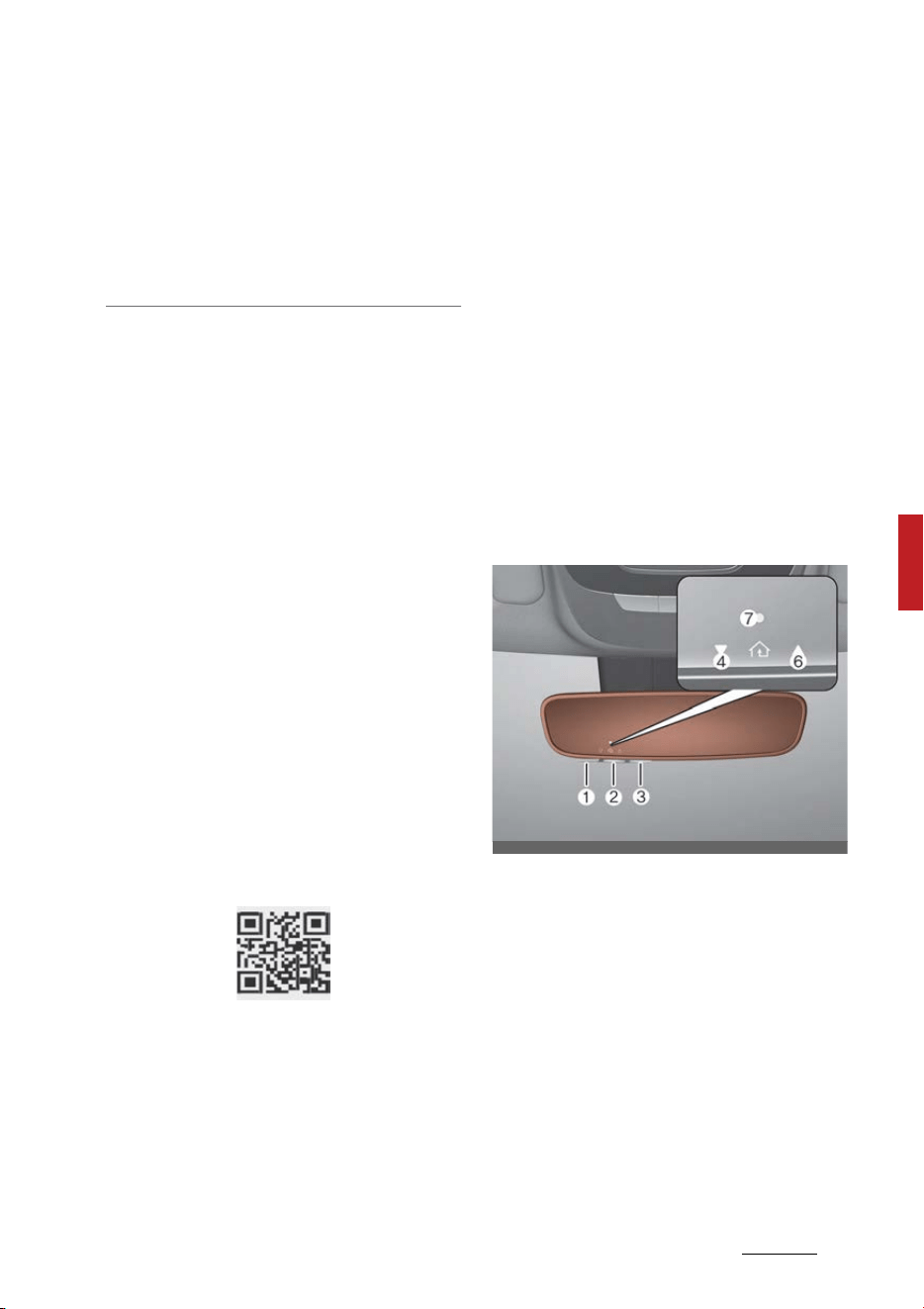
67
5
5
Features of your vehicle Mirrors
It is also recommended that a new
battery be replaced in the hand-
held transmitter of the device being
trained to HomeLink for quicker
training and accurate transmission
of the radio frequency.
1. Programming HomeLink
The following steps show how to
program HomeLink. If you have any
questions or are having difficulty
programming your HomeLink but
-
tons, refer to the HomeLink website
or call the HomeLink customer sup
-
port toll-free number. Do this,
before going back to the dealer who
sold you the car.
䳜 Visit the HomeLink website at:
www.homelink.com. Then at the
top of the page, choose your
vehicle make. Then watch the You
Tube video, and/or access addi
-
tional website information.
䳜 If you choose to access the web
-
site via your cell phone, scan the
QR code.
䳜 Or, call HomeLink customer sup
-
port at 1-800-355-3515
(Please have the vehicle make/
model AND the opener device
make/model readily available.)
1) Programming Preparation
1. When programming a garage door
opener, it is advised to park the
vehicle outside of the garage.
2. It is recommended that a new
battery be placed in the hand-
held transmitter of the device
being programmed to HomeLink
for quicker training and accurate
transmission of the radio-fre
-
quency signal.
3. Press the ENGINE START/STOP
button to the ACC (Accessory)
position for programming of
HomeLink.
2) Programming a New HomeLink
Button
1. Press and release the HomeLink
button (1), (2) or (3), you would
like to program. The HomeLink
indicator light (7) will flash orange
slowly (if not, perform the steps
of "Erasing HomeLink Buttons"
section, and start over).
OMQ4041545N
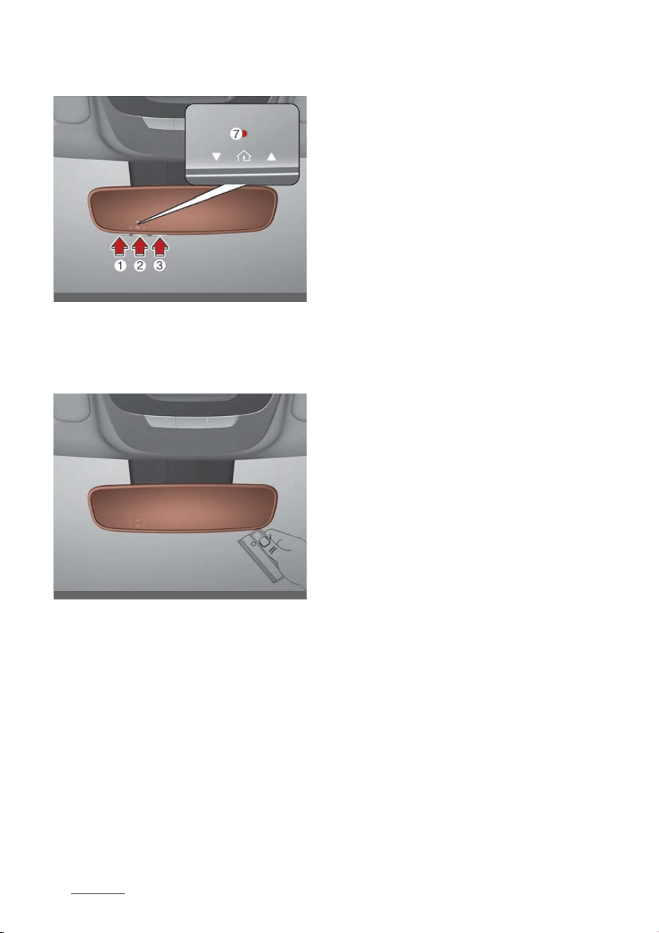
Features of your vehicle
685
Mirrors
2. Position the garage door opener
remote 1 - 3 inches (2 - 8 cm)
away from the HomeLink but
-
tons.
3. While the HomeLink indicator light
(7) is flashing orange, press and
hold the hand-held remote but
-
ton. Continue pressing the hand-
held remote button until the
HomeLink indicator light (7) light
changes from orange to green.
You may now release the hand-
held remote button.
4. Wait until your garage door
comes to a complete stop,
regardless of position, before pro
-
ceeding to the next steps.
5. Press and release the HomeLink
button you are programming and
observe the indicator light.
䳜 If the indicator light remains
solid green, your device should
operate when the HomeLink
button is pressed. At this point,
if your device operates, pro
-
gramming is complete.
䳜 If the indicator light rapidly
flashes green, firmly press, hold
for two seconds and release the
HomeLink button up to three
times in a row slowly to com
-
plete the programming process.
Do not press the HomeLink but
-
ton rapidly. At this point if your
device operates, programming
is complete. If the device does
not operate, continue with step
6.
6. At the garage door opener motor,
(security gate motor, etc.) locate
the "Learn", "Smart", "Set" or
"Program" button. This can usu
-
ally be found where the hanging
antenna wire is attached to the
motor-head unit (see the device's
manual to identify this button).
The name and color of the button
may vary by manufacturer.
OMQ4041546N
OMQ4041547N
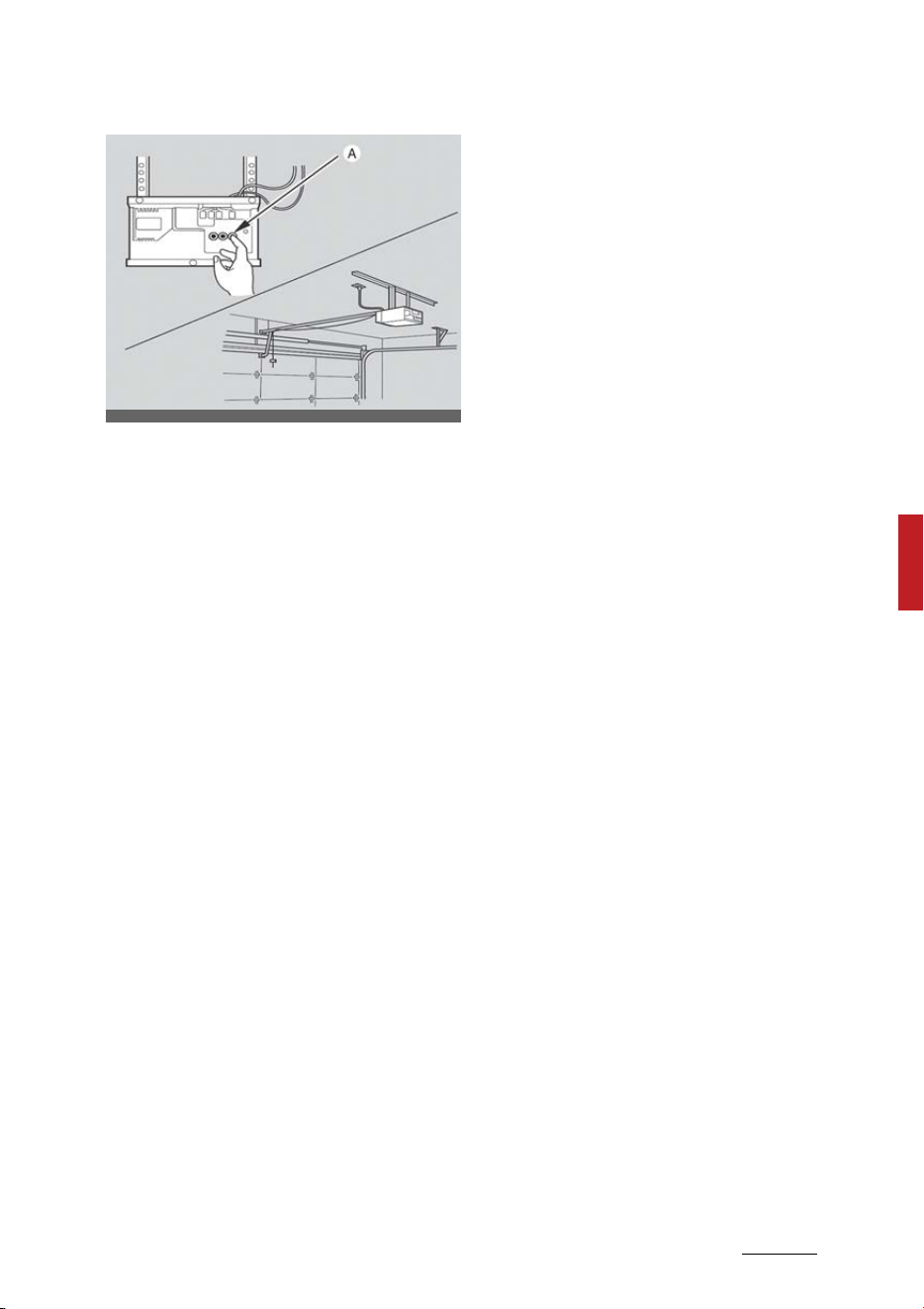
69
5
5
Features of your vehicle Mirrors
* A ladder and/or second person
may simplify the following
steps.
7. Firmly press and release the
"Learn" ,"Smart", "Set" or "Pro
-
gram"" button. You now have up
to 30 seconds in which to com
-
plete the next step.
8. Return to the vehicle and firmly
press, hold for two seconds and
release, the HomeLink button up
to three times in a row slowly. Do
not press the HomeLink button
rapidly. As soon as you see the
garage door start to move, stop
pressing any buttons until a few
seconds after the garage door
has come to a complete stop,
regardless of position. At this
point programming is complete
and your device should operate
when the HomeLink button is
pressed and released.
3) Two-Way Communication Pro
-
gramming (For select garage door
openers)
If your garage door opener has the
'myQ' logo on its side, your opener
has Two-Way Communication capa
-
bility. HomeLink has the capability
to establish Two-Way Communica
-
tion with your garage door opener.
HomeLink can receive and display
"closing" or "opening" status mes
-
sages from compatible garage door
openers. At any time, HomeLink can
also recall and display the last
recorded status communicated by
the garage door opener to indicate
your garage door being "closed" or
"opened".
To check if your garage door opener
is compatible with this feature,
refer to www.homelink.com/com
-
patible/Two-way-Communication. If
your garage door opener has this
functionality, AND the Two-Way
Communication indicators (4), (6) in
the mirror appear while the garage
door is opening/closing, then no fur
-
ther steps are needed. Two-Way
Communication Programming is
already complete. However, if your
garage door opener has this func
-
tionality, AND the Two-Way Com
-
munication indicators (4), (6) in the
mirror DO NOT appear while the
garage door is opening/closing, use
the following instructions to enable
this functionality.
ODL3A040504

Features of your vehicle
705
Mirrors
1. In your vehicle, press and hold the
programmed HomeLink button
for 2 seconds, then release. Con
-
firm that the garage door is mov
-
ing. AFTER it stops, you will have
one minute to complete the fol
-
lowing steps:
* A ladder and/or second person
may simplify the following
steps.
2. On your garage door opener in
your garage, locate the "Learn"
button (usually near where the
hanging antenna wire is attached
to the garage door opener). If
there is difficulty locating this
button, refer to the device's
owner's manual.
3. Press and release the "Learn"
button.
4. A light on your garage door
opener may flash, and your Two-
Way Communication indicators
(4), (6) in your vehicle may flash,
confirming completion of the pro
-
cess.
5. Return to the vehicle and firmly
press and release the pro
-
grammed HomeLink button to
activate your garage door. The
Two-Way Communication indica
-
tors (4), (6) flash in orange when
the door is moving. Do not make
any additional button presses
until AFTER the garage door has
come to a complete stop.
6. Your Two-Way Communication
programming is now complete.
NOTICE
If your garage door opener has
Two-Way Communication function
-
ality, it is possible for HomeLink to
stop functioning the garage door
shortly after initial programming, if
the Two-Way Communication Pro
-
gramming wasn't properly com
-
pleted. This usually happens after
the first 10 times a programmed
HomeLink button is pressed. If you
experience this, completing the
"Programming a New HomeLink
Button" and "Two-Way Communica
-
tion Programming" will restore door
operation.
4) Canadian Programming
Canadian radio-frequency laws
require transmitter remote signals
to "time-out" (or quit) after a couple
seconds of transmission, which may
not be long enough for HomeLink to
pick up the signal during program
-
ming.
If you live in Canada or you are hav
-
ing difficulties programming a gate
operator or garage door opener by
using the programming procedures,
replace "Programming a New
HomeLink Button" step 3 with the
following:
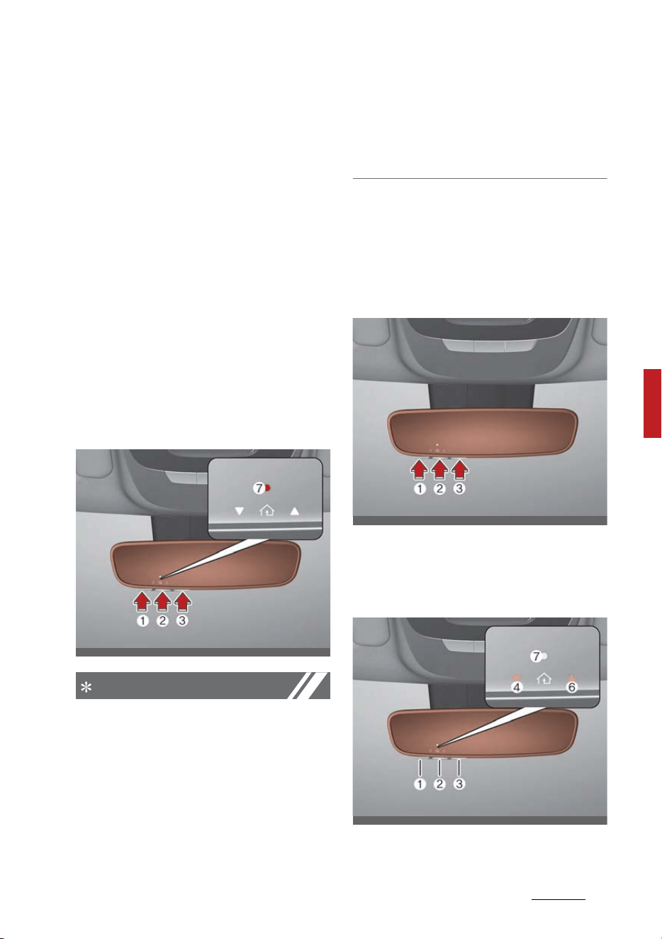
71
5
5
Features of your vehicle Mirrors
While the HomeLink indicator light
(7) is flashing orange, press and
release ("cycle") your device's hand-
held remote every two seconds until
the HomeLink indicator light (7)
changes from orange to green. You
may now release the hand-held
remote button. Then proceed with
"Programming a New HomeLink
Button" step 4.
2. Operating HomeLink
1) Operating HomeLink
1. Press and release the desired
programmed HomeLink button (1,
2 or 3).
NOTICE
The HomeLink indicator (7) should
light green, solid or flashing, and
your programmed device should
operate.
If your device does not operate, the
HomeLink programming was not
successful, and you'll need to repro
-
gram the button.
2) Two-Way Communication Dis
-
play Behavior
1. Press and release one of the pro
-
grammed HomeLink buttons (1, 2
or 3)
2. The indicator (4) and (6) operates
as below, if your garage door
opener has Two-Way Communi
-
cation functionality.
OMQ4041546N
OMQ4041549N
OMQ4041548N

Features of your vehicle
725
Mirrors
䳜 If the indicator (4) flashes in
Orange, it indicates that the
garage door is "Closing".
䳜 The indicator (4) turns solid
green once the garage door has
closed.
䳜 If the indicator (6) flashes in
Orange, it indicates that the
garage door is "Opening".
䳜 The indicator (6) turns solid
green once the garage door has
fully opened.
䳜 If the indicator (4) or (6) does
not turn to green, it indicates
that the last status of garage
door was not received properly.
The HomeLink mirror tries to
receive the last known status of
the garage door for a few sec
-
onds.
3) Recalling Garage Door Status
HomeLink mirror with Two-Way
Communication provides a way to
view the last stored message from
the garage door opener. In order to
recall the last known status of the
last activated device, press the but
-
tons "1 and 2" OR "2 and 3" simulta
-
neously.
䳜 If the indicator (4) appears solid
Green, it indicates that the last
activated device was "closed"
properly.
䳜 If the indicator (6) appears solid
Green, it indicates that the last
activated device was "open" prop
-
erly.
3. Erasing HomeLink Buttons
1) Erasing and Reprogramming a
Single HomeLink Button:
1. Press and hold the desired Home
-
Link button you want to re-pro
-
gram. DO NOT release the button.
2. The HomeLink indicator light (7)
will illuminate solid green. Release
the button as soon as the Home
-
Link indicator light (7) begins to
flash orange, usually about 20
seconds.
3. Proceed with the steps in the
"Programming a New HomeLink
Button" section.
NOTICE
If you do not complete the re-pro
-
gramming of a new device to the
button, it will revert to the previ
-
ously stored programming
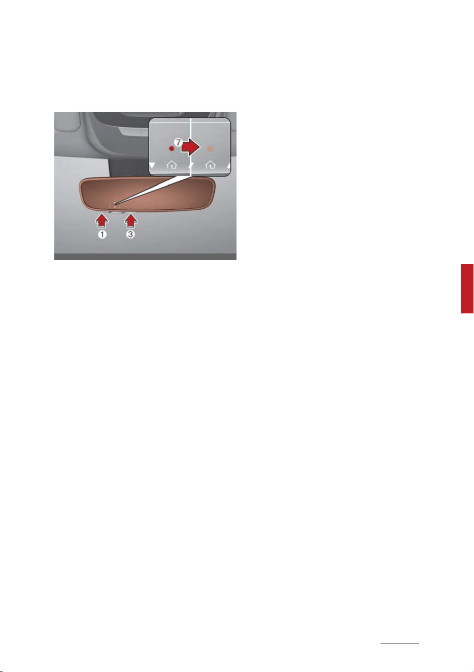
73
5
5
Features of your vehicle Mirrors
2) The following instructions will
erase ALL HomeLink program
-
ming from ALL buttons:
1. Press and hold the buttons (1)
and (3) simultaneously
2. The HomeLink indicator light (7)
will illuminate solid Orange for
about 10 seconds
3. Release the buttons once the
HomeLink indicator light (7)
changes to Green and flashes
rapidly
4. Now all three HomeLink buttons
(1), (2) and (3) are cleared of any
programming
Information
HomeLink and the HomeLink House
logo are registered trademarks of
Gentex Corporation.
The myQ logo is a registered trade
-
mark of The Chamberlain Group, Inc
FCC (USA) and ISED (Canada)
This device complies with FCC rules
part 15 and Innovation, Science, and
Economic Development Canada
RSS-210. Operation is subject to the
following two conditions: (1) This
device may not cause harmful inter
-
ference, and (2) This device must
accept any interference that may
be received including interference
that may cause undesired opera
-
tion. WARNING: The transmitter has
been tested and complies with FCC
and ISED rules. Changes or modifi
-
cations not expressly approved by
the party responsible for compliance
could void the user's authority to
operate the device.
This equipment complies with FCC
and ISED radiation exposure limits
set forth for an uncontrolled envi
-
ronment. End Users must follow the
specific operating instructions for
satisfying RF exposure compliance.
This transmitter must be at least 20
cm from the user and must not be
co-located or operating in conjunc
-
tion with any other antenna or
transmitter.
FCC (tats-Unis) et ISED (Canada)
Cet appareil est conforme aux
rglements de la FCC, section 15, et
au CNR-210 d'Innovation, Sciences
et Dveloppement conomique Can
-
ada. Le fonctionnement est assu
-
OMQ4041550N

Features of your vehicle
745
Mirrors
jetti aux deux conditions suivantes:
(1) cet appareil ne doit pas causer
d'interfrences nuisibles et (2) cet
appareil doit accepter toute inter
-
frence reue, y compris celle qui
pourrait entraner un dys
-
fonctionnement. MISE EN GARDE:
L'metteur a subi des tests et est
conforme aux rglements de la FCC
et d'ISDE. Les changements ou
modifications non approuvs explic
-
itement par la partie responsable de
la conformit pourraient rendre
caduque l'autorisation de l'utilisa
-
teur de se servir du dispositif.
Cet appareil est conforme aux lim
-
ites d'exposition aux radiations de la
FCC et d'ISDE tablies pour un envi
-
ronnement non contrl. Les utilisa
-
teurs finaux doivent respecter les
instructions d'utilisation spcifiques
pour satisfaire aux exigences de
conformit aux expositions de RF.
L'metteur doit se trouver 20 cm
au minimum de l'utilisateur et ne
doit pas tre situ au mme endroit
que tout autre metteur ou antenne
ni fonctionner avec un autre met
-
teur ou antenne.
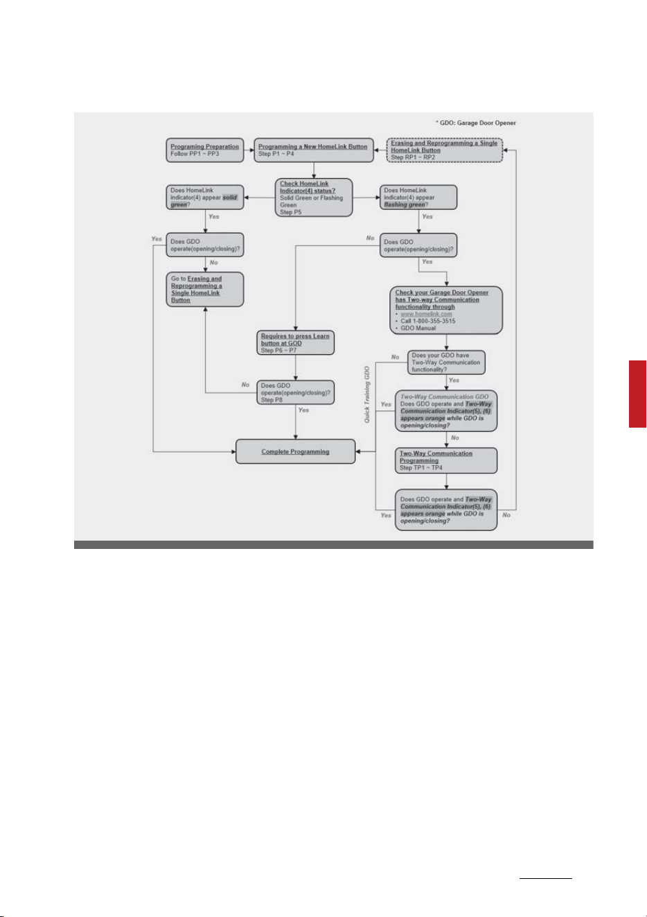
75
5
5
Features of your vehicle Mirrors
HomeLink 5 Programing Flow Chart
ODL3A040518

Features of your vehicle
765
Mirrors
Outside rear view mirror
Your vehicle is equipped with both
left-hand and right-hand outside
rear view mirrors.
Be sure to adjust the mirror angles
before driving.
The mirrors can be adjusted
remotely with the control levers or
remote switch, depending on the
type of mirror control installed. The
mirror heads can be folded back to
prevent damage during an auto
-
matic car wash or when passing
through a narrow street.
WARNING
Rear view mirrors
䳜 The outside rear view mirror is
convex. Objects seen in the mirror
are closer than they appear.
䳜 Use your interior rear view mirror
or direct observation to deter
-
mine the actual distance of fol
-
lowing vehicles when changing
lanes.
CAUTION
Do not scrape ice off the mirror
face; this may damage the surface
of the glass. If ice should restrict the
movement of the mirror, do not
force the mirror for adjustment. To
remove ice, use a deicer spray, or a
sponge or soft cloth with warm
water.
CAUTION
If the mirror is jammed with ice, do
not adjust the mirror by force. Use
an approved spray de-icer (not radi
-
ator antifreeze) to release the fro
-
zen mechanism or move the vehicle
to a warm place and allow the ice to
melt.
WARNING
Do not adjust or fold the outside
rear view mirrors while the vehicle is
moving. This could result in loss of
control, and an accident which could
cause DEATH, SERIOUS INJURY, or
property damage.
Adjusting the outside rear view
mirrors
The electric remote control mirror
switch allows you to adjust the
position of the left and right outside
rear view mirrors.
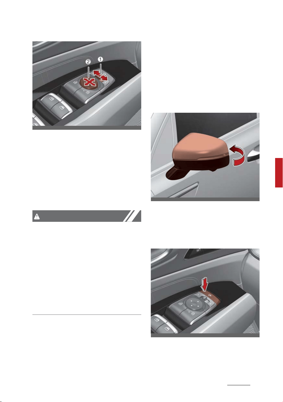
77
5
5
Features of your vehicle Mirrors
Adjusting the rear view mirrors:
1. Move the R or L switch (1) to
select the right side mirror or the
left side mirror.
2. Press a corresponding point on
the mirror adjustment control (2)
to position the selected mirror up,
down, left or right.
CAUTION
䳜 The mirrors stop moving when
they reach the maximum adjust
-
ing angles, but the motor contin
-
ues to operate while the switch is
pressed. Do not press the switch
longer than necessary, the motor
may be damaged.
䳜 Do not attempt to adjust the out
-
side rear view mirror by hand.
Doing so may damage the parts.
Folding the outside rear view mir
-
ror
Manual type (if equipped)
To fold the outside rear view mirror,
grasp the housing of the mirror and
then fold it toward the rear of the
vehicle.
Electric type (if equipped)
The outside rear view mirror can be
folded or unfolded by pressing the
switch as below.
䳜 To fold the outside rear view mir
-
ror depress the button.
䳜 To unfold it, depress the button
again.
OMQ4AH040447
OMQ4040031
OMQ4AH040448
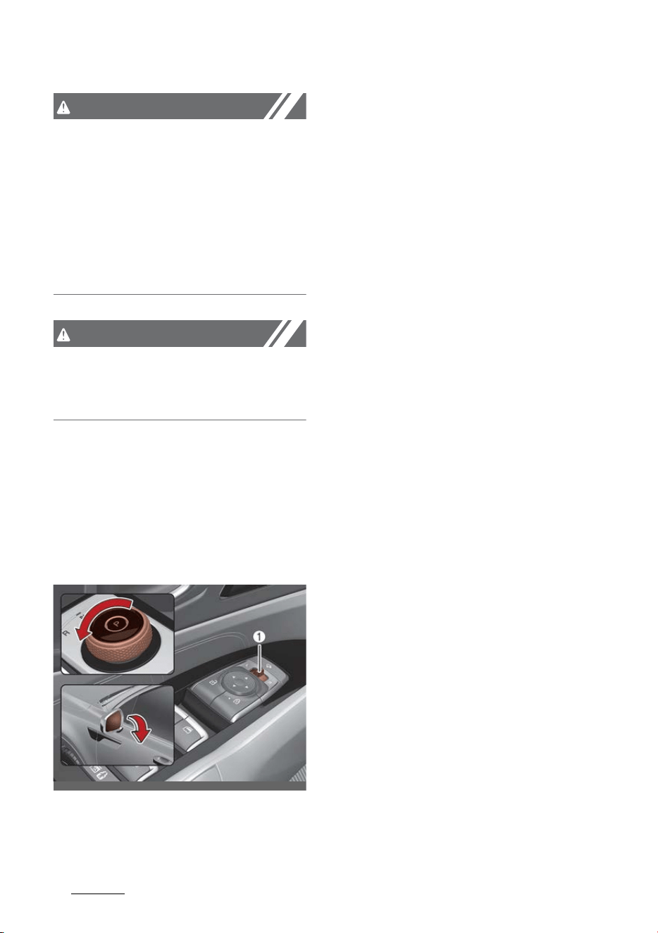
Features of your vehicle
785
Mirrors
CAUTION
The electric type outside rear view
mirror operates even though the
ENGINE START/STOP button is in
the LOCK or OFF position. However,
to prevent unnecessary battery dis
-
charge, do not adjust the mirrors
longer than necessary while the
engine is not running.
CAUTION
In case it is an electric type outside
rear view mirror, don't fold it by
hand. It could cause motor failure.
Reverse parking aid function (if
equipped)
When you shift the gear to the R
(Reverse) position, the outside rear
view mirror(s) will rotate down
-
wards to aid with driving in reverse.
The position of the outside rear
view mirror switch (1) determines
whether or not the mirrors will
move:
Left/Right: When either the L (Left)
or R (Right) switch is selected, both
outside rear view mirrors will move.
Neutral: When neither switch is
selected, the outside rear view mir
-
rors will not move.
The outside rear view mirrors will
automatically revert to their original
positions if any of the followings
occur:
䳜 The ENGINE START/STOP button
is placed to either the LOCK/OFF
position or the ACC position.
䳜 The gear is shifted to any position
except R (Reverse).
䳜 The remote control outside rear
view mirror switch is not selected.
Auto reverse user settings
If you cannot secure enough visibil
-
ity with the angles provided as fac
-
tory default conditions, you can
readjust and store the angles of
outside rear view mirrors.
The factory default angles of the
right and left rear view mirrors
might be set differently to improve
visibility.
1. Set the shift dial SBW to P (Park
-
ing). Make sure that the vehicle is
stopped and the mirrors are not
working.
OMQ4AH040032

79
5
5
Features of your vehicle Mirrors
2. Position the lever to L (left) or R
(right) depending on the mirror
that you want to adjust.
3. Step on the brake pedal and turn
the shift dial SBW to R (Reverse).
4. When the downward movement
of the rear view mirror is finished,
adjust the mirror to the desired
angle by pressing the switches, ▼
, ▲, ◀, ▶.
5. If you change the shift dial SBW to
a position other than R (Reverse),
or change the rear view mirror
selector lever to the neutral posi
-
tion, and the automatic return of
the mirror is finished, the
adjusted angle will be automati
-
cally saved.
6. You can adjust the rear view mir
-
ror on the other side by following
the same procedures (1-5).
How to reset auto reverse user
settings
If you want to change the automatic
control function of rear view mirrors
to factory-default conditions, follow
the steps below.
1. Position the shift dial SBW to P
(Park). Make sure that the vehicle
is stopped and the mirror is not
working.
2. Choose the mirror to be adjusted
by positioning the lever to L (left)
or R (right).
3. Step on the brake pedal and turn
the shift dial SBW to R (Reverse).
4. When the downward movement
of the rear view mirror is finished,
press the switch ▲ to locate the
mirror in the position higher than
before (P, N or D).
(Adjust the mirror in the higher
position compared to its position
in the driving mode)
5. It is initialized when the shift dial
SBW is changed to a position
other than R (Reverse), or the
rear view mirror selector lever is
changed to the neutral position.
(Initialized position will be applied
from next operation)
6. You can initialize settings for the
mirror on the other side by fol
-
lowing the same procedures (1-
5).
CAUTION
We recommend following the proce
-
dures in an orderly manner to
change or initialize the auto revers
-
ing user settings.
If you move to the next step before
completing the previous one, the
changed angle may not be changed
or initialization may not work prop
-
erly.
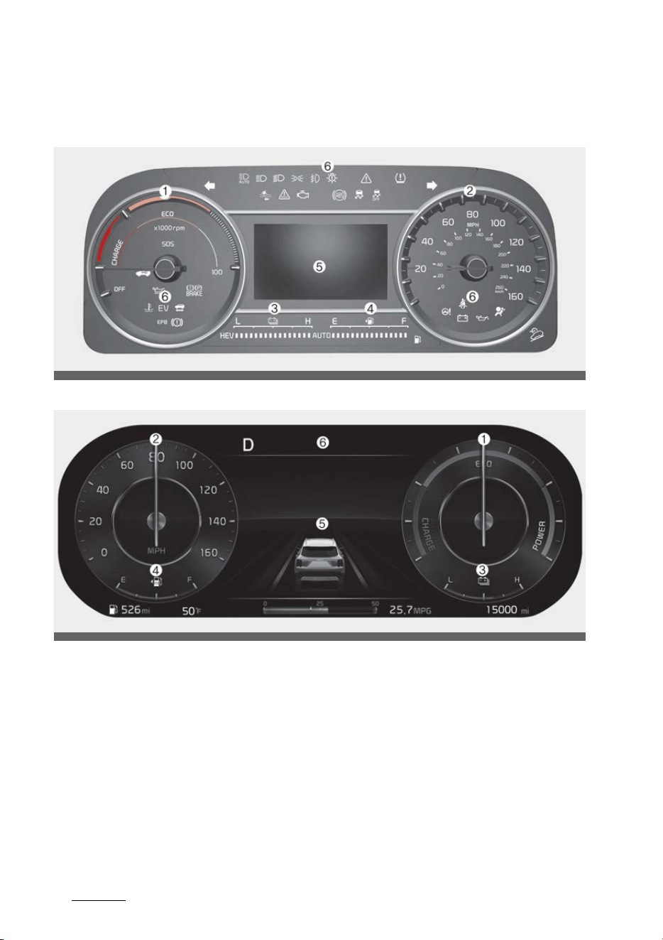
Features of your vehicle
805
Instrument cluster
Instrument cluster
Conventional cluster (Type A)
Full LCD cluster (Type B)
* The actual cluster in the vehicle may differ from the illustration.
1. Power gauge
2. Speedometer
3. Hybrid battery SOC gauge
4. Fuel gauge
5. LCD display (including Trip computer)
6. Warning and indicator lights
OMQ4AH040106
OMQ4AH041100
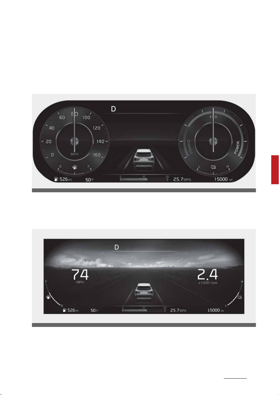
81
5
5
Features of your vehicle Instrument cluster
Full LCD cluster (if equipped)
The full LCD type cluster provides two themes.
Type A
Type A is the basic theme of the full LCD type cluster and provides different
graphic styles depending on drive mode.
Type B (Dynamic)
Type B is set by the user and provides digital display. The background screen
changes according to the weather and time.
䳜 Weather: sunny, cloudy, rainy, or snowy (4 types)
䳜 Time: night, day, sunrise and sunset (4 types)
You can change the theme by selecting 'Vehicle → Instrument Cluster Setting →
Theme Selection' on the menu.
OMQ4AH041101
OMQ4AH041109
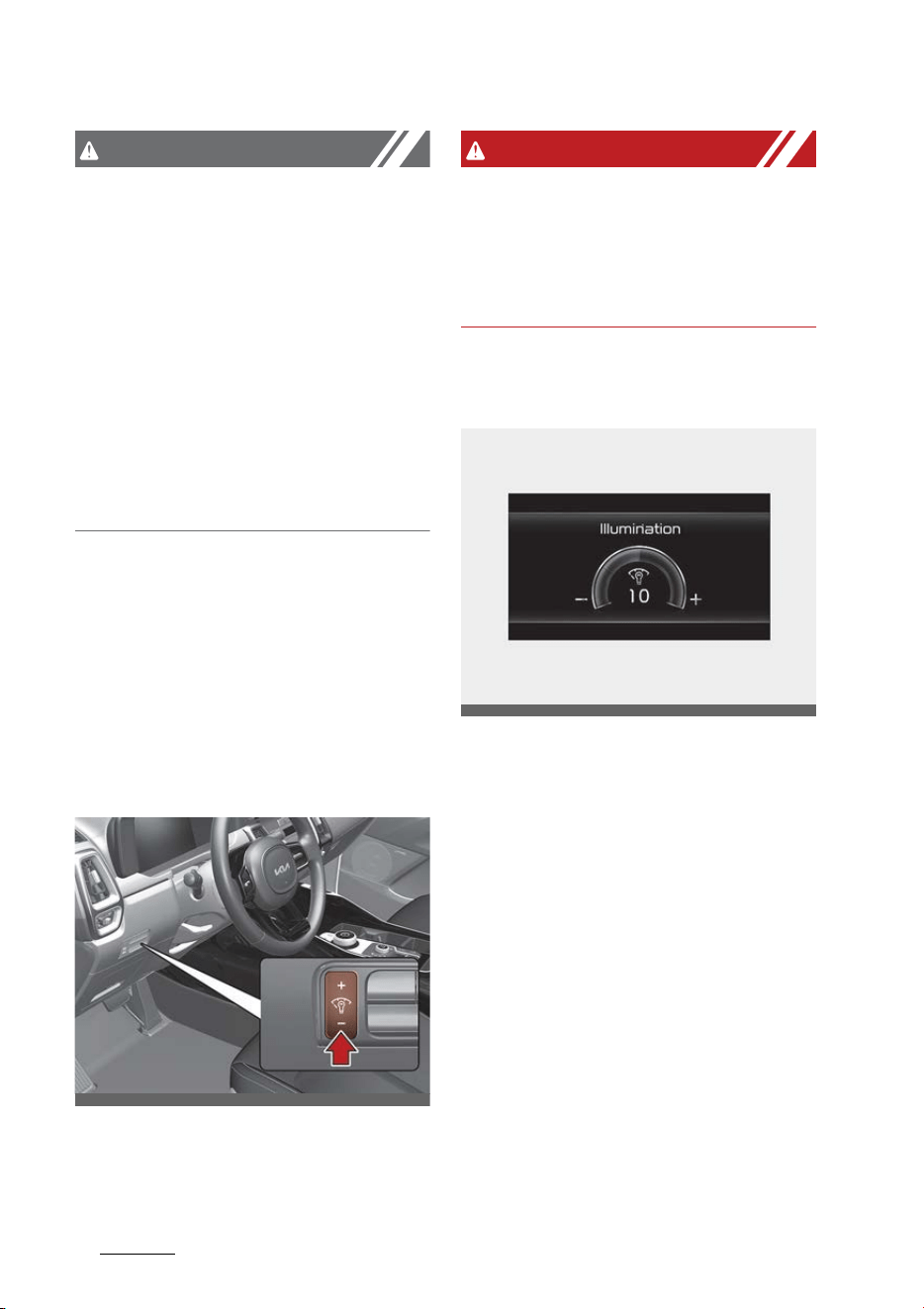
Features of your vehicle
825
Instrument cluster
CAUTION
The information is displayed after
getting information from a weather
information provider via GPS.
Depending on conditions of GPS
reception, the information may be
different from the current weather
in your area.
If no information is received via GPS
(e.g., not subscribed to UVO service),
the weather and time will be dis
-
played as 'sunny' and 'night' on the
cluster.
Adjusting instrument cluster illumi
-
nation
The brightness of the instrument
panel illumination is changed by
pressing the illumination control
button ("+" or "-") when the ENGINE
START/STOP button is ON, or the
taillamps are turned on.
WARNING
Never adjust the instrument cluster
while driving. This could result in
loss of control and lead to an acci
-
dent that may cause DEATH, SERI
-
OUS INJURY, or property damage.
䳜 If you hold the illumination control
button ("+" or "-"), the brightness
will be changed continuously.
䳜 If the brightness reaches to the
maximum or minimum level, an
alarm will sound.
OMQ4AH041049
OMQ4AH040558
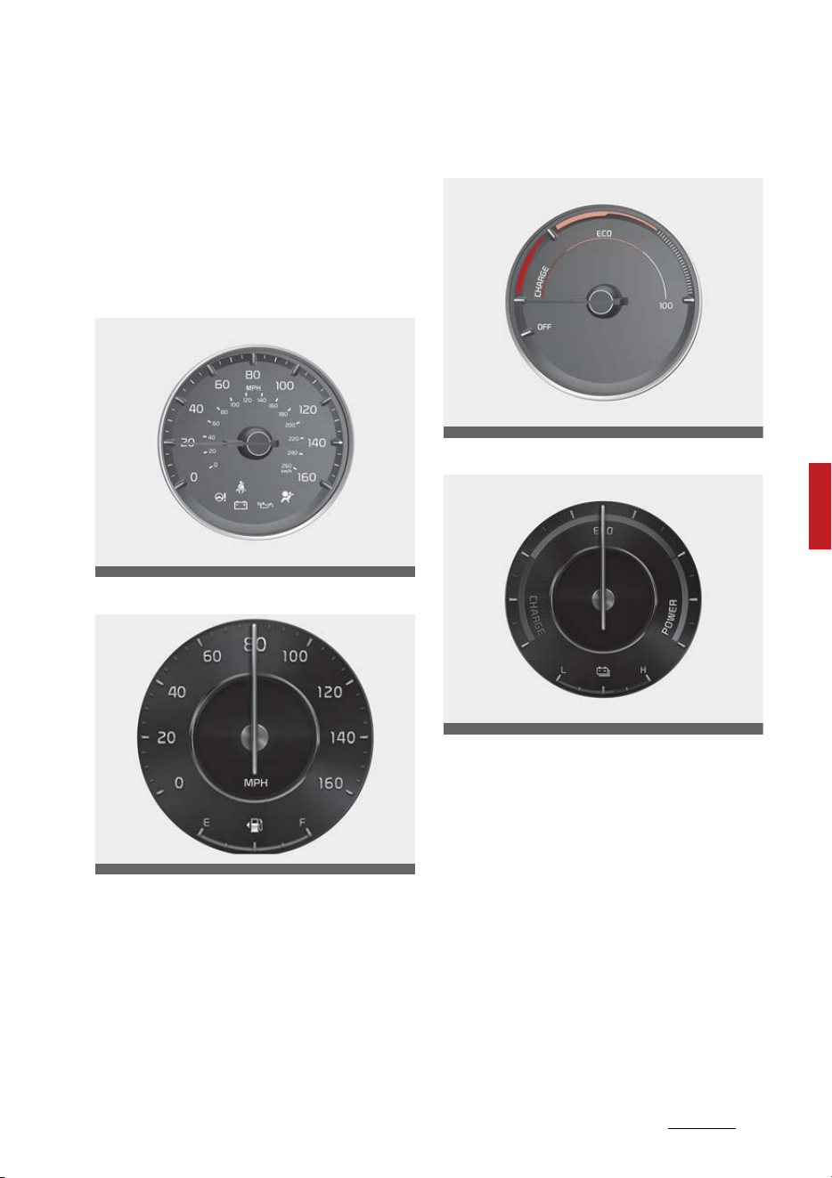
83
5
5
Features of your vehicle Instrument cluster
Gauges
The gauges display various informa
-
tion such as the speed of the vehi
-
cle, and so on.
Speedometer
Type A
Type B
The speedometer indicates the
speed of the vehicle and is cali
-
brated in kilometers per hour (km/h)
and miles per hour (mph).
Power gauge
Type A
Type B
The hybrid system gauge indicates
whether the current driving condi
-
tion is fuel efficient or not.
䳜 CHARGE:
Shows that the energy made by
the vehicle is being converted to
electrical energy. (Regenerated
energy)
䳜 ECO:
Shows that the vehicle is being
driven in an Eco-friendly manner.
䳜 POWER:
OMQ4040156L
OMQ4AH040164
OMQ4H040105
OMQ4H040103
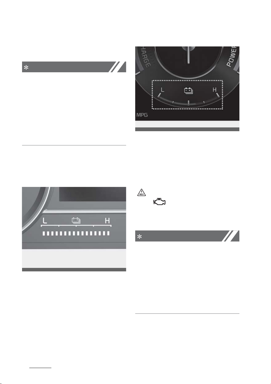
Features of your vehicle
845
Instrument cluster
Shows that the vehicle is exceed
-
ing the Eco-friendly range.
NOTICE
According to the hybrid system
gauge area, the "EV" indicator
comes on or off.
䳜 "EV" indicator ON : Vehicle is
driven using the electric motor or
the gasoline engine is stopped.
䳜 "EV" indicator OFF : Vehicle is
driven using the gasoline engine.
Hybrid battery SOC (State of
Charge) gauge
Type A
Type B
This gauge indicates the remaining
hybrid battery power. If the SOC is
near the "L (Low)" level, the vehicle
automatically operates the engine
to charge the battery.
However, if the Service Indicator
( ) and Malfunction Indicator Lamp
(MIL) ( ) turn on when the SOC
gauge is near the "L (Low)" level,
visit an authorized Kia dealer.
NOTICE
Never try to start the vehicle if the
fuel tank is empty. In this condition,
the engine cannot charge the high
voltage battery of the hybrid sys
-
tem. If you try to start the vehicle
when the fuel is empty, the high
voltage battery will become dis
-
charged and be damaged.
OMQ4H040107
OMQ4AH040104
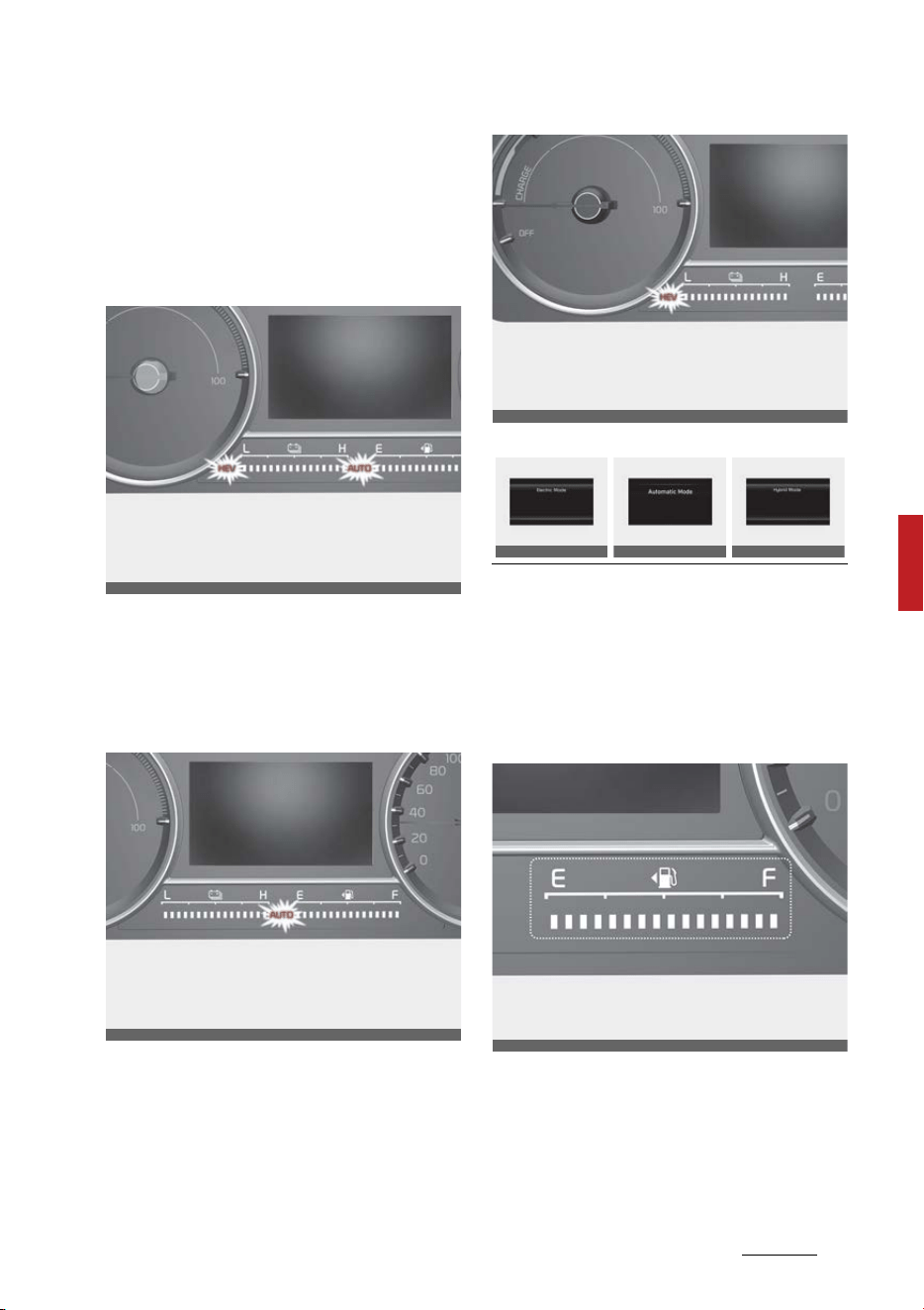
85
5
5
Features of your vehicle Instrument cluster
Plug-in hybrid mode indicator
(Plug-in hybrid vehicle)
䳜 CD (Charge Depleting, Electric)
mode: The high-voltage (hybrid)
battery is used to drive the vehi
-
cle.
䳜 AUTO mode: The AUTO mode will
be automatically selected from
either from Electric (CD) mode or
Hybrid (CS) mode by the system
according to the driving condition.
䳜 CS (Charge Sustaining, Hybrid)
mode: The high-voltage (hybrid)
battery and gasoline engine is
used to drive the vehicle.
A corresponding message is dis
-
played to indicate the selected
mode.
Fuel gauge
Type A
OMQ4PH050353L
OMQ4PHQ010045L
OMQ4PHQ010046L
OMQ4PH050364L
OMQ4PH050360L
OMQ4PH050366L
OMQ4040154
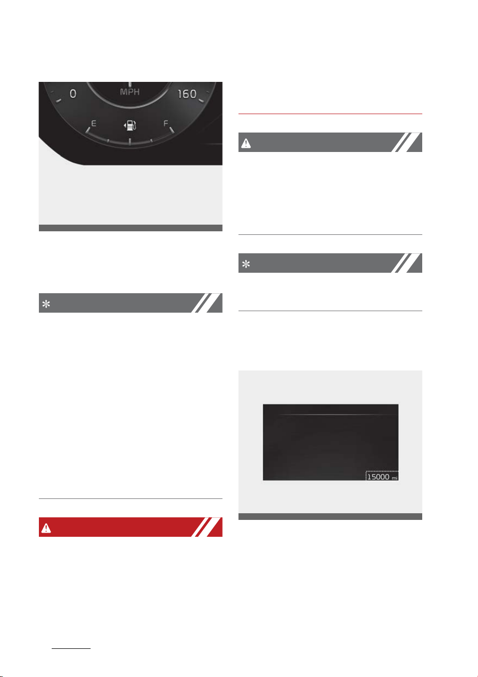
Features of your vehicle
865
Instrument cluster
Type B
This gauge indicates the approxi
-
mate amount of fuel remaining in
the fuel tank.
NOTICE
䳜 The fuel tank capacity is given in
"Recommended lubricants and
capacities" on page 9-8.
䳜 The fuel gauge is supplemented
by a low fuel warning light, which
will illuminate when the fuel tank
is nearly empty.
䳜 On inclines or curves, the fuel
gauge pointer may fluctuate or
the low fuel warning light may
come on earlier than usual due to
the movement of fuel in the tank.
WARNING
Fuel gauge
Running out of fuel can expose vehi
-
cle occupants to danger.
You must stop and obtain additional
fuel as soon as possible after the
warning light comes on or when the
gauge indicator comes close to the "
E" level.
CAUTION
Avoid driving with an extremely low
fuel level. Running out of fuel could
cause the engine to misfire, which
could damage the catalytic con
-
verter.
NOTICE
The fuel display may not be accu
-
rate if the vehicle is on an incline.
Odometer
Type A
ODL3A040513
OMQ4AH040113
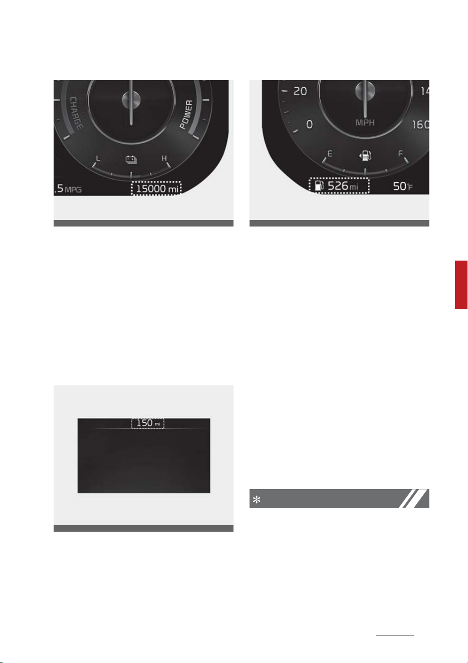
87
5
5
Features of your vehicle Instrument cluster
Type B
The odometer Indicates the total
distance that the vehicle has been
driven and should be used to deter
-
mine when periodic maintenance
should be performed.
䳜 Odometer range: 0~1,599,999 km
or 999,999 miles.
Distance to empty
Type A
Type B
䳜 The distance to empty is the esti
-
mated distance the vehicle can be
driven with the remaining fuel.
- Distance range: 1~9,999 km or
1~9,999 mi.
䳜 If the estimated distance is below
1 mile (1 km), the trip computer
will display "---" as distance to
empty.
䳜 If the level of the remaining fuel is
more than three-quarters, more
than 0.8 gallons (3 liters) of fuel
must be refilled for the fuel gauge
to change. In other cases, more
than 1.6 gallons (6 liters) of fuel
must be refilled for the vehicle to
change the fuel gauge.
NOTICE
䳜 If the vehicle is not on level ground
or the battery power has been
interrupted, the distance to
empty function may not operate
correctly.
䳜 The distance to empty may differ
from the actual driving distance
OMQ4AH040155
OMQ4AH040115
ODL3A040112
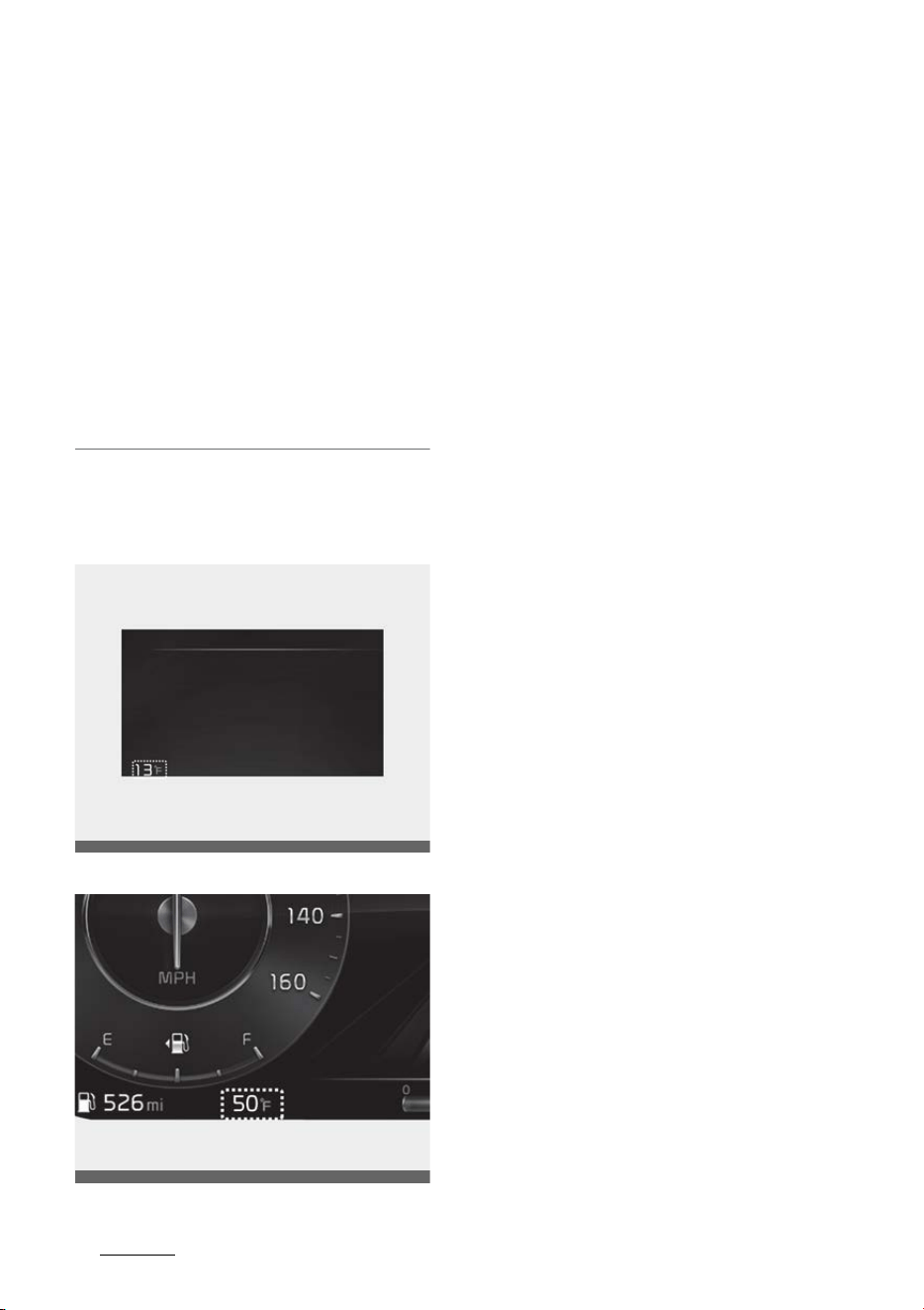
Features of your vehicle
885
Instrument cluster
as it is an estimate of the avail
-
able driving distance.
䳜 The trip computer may not regis
-
ter additional fuel if less than 1.6
gallons (6 liters) of fuel are added
to the vehicle.
䳜 The fuel economy and distance to
empty may vary significantly
based on driving conditions, driv
-
ing habits, and condition of the
vehicle.
Outside temperature gauge
Type A
Type B
This gauge indicates the current
outside air temperatures by 1 F (1
C).
䳜 Temperature range: -40 F~140
F (-40 C~60 C)
The outside temperature on the
display may not change immedi
-
ately like a general thermometer to
prevent the driver from being inat
-
tentive.
To change the temperature unit
(from C to F or from F to C)
The temperature unit can be
changed by using the "User Set
-
tings" mode of the LCD Display.
* For more details, refer to "LCD dis
-
play" on page 5-90.
Transmission shift indicator
Transmission shift indicator displays
gear information depending on your
vehicle's transmission type.
OMQ4AH040117
ODL3A040113
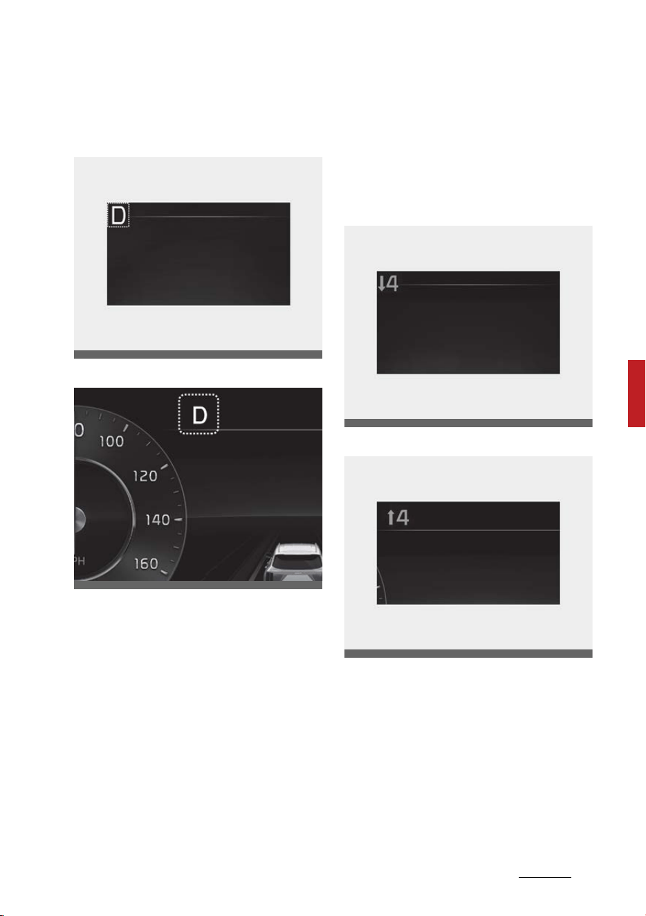
89
5
5
Features of your vehicle Instrument cluster
Automatic transmission shift indi
-
cator
Type A
Type B
This indicator displays which auto
-
matic transmission gear is selected.
䳜 Park: P
䳜 Reverse: R
䳜 Neutral: N
䳜 Drive: D
Manual shift mode
䳜 Shifting up: ▲2, ▲3, ▲4, ▲5, ▲6
䳜 Shifting down: ▼1, ▼2, ▼3, ▼4,
▼5
Automatic transmission shift indi
-
cator in manual shift mode
In the Manual shift mode, this indi
-
cator informs which gear is desired
while driving to save fuel.
Type A
Type B
䳜 Shifting up: ▲2, ▲3, ▲4, ▲5, ▲6
䳜 Shifting down: ▼1, ▼2, ▼3, ▼4,
▼5
For example
䳜 ▲3: Indicates that shifting up to
the 3rd gear is desired (currently
the shift dial SBW is in the 2nd or
1st gear).
OMQ4040120
OMQ4AH051327
OMQ4040494L
OMQ4040493L
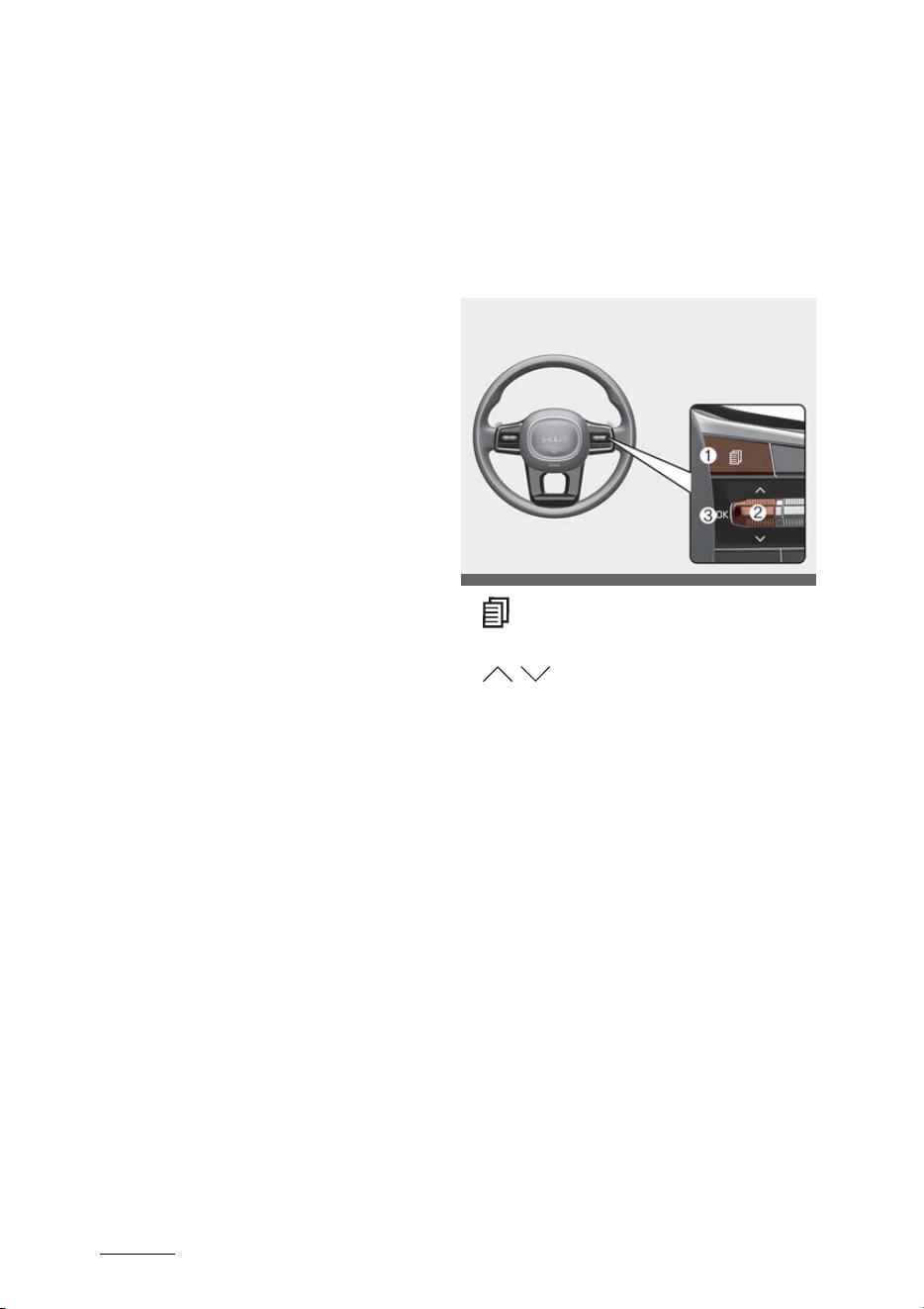
Features of your vehicle
905
LCD display
䳜 ▼3: Indicates that shifting down
to the 3rd gear is desired (cur
-
rently the shift dial SBW is in the
4th, 5th or 6th gear).
When the system is not working
properly, the indicator is not dis
-
played.
Shift indicator pop-up
The pop-up that indicates the cur
-
rent gear position is displayed in the
cluster for about 2 seconds when
shifting into other positions (P/R/N/
D).
The shift indicator pop-up function
can be activated or deactivated
from the User Settings mode in the
cluster LCD display.
LCD display
The LCD display modes can be
changed with the control buttons.
LCD Display Control
1. : MODE button for changing
modes
2. / : MOVE switch for changing
items
3. OK: SELECT/RESET button for
setting or resetting the selected
item
OMQ4041034
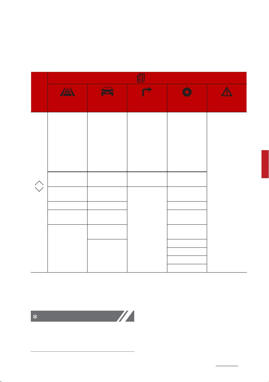
91
5
5
Features of your vehicle LCD display
LCD display modes
The LCD display provides 5 modes. You can switch modes by pressing the
Mode button.
The information provided may differ depending on which functions are
applicable to your vehicle.
* : if equipped
NOTICE
Keep the engine running when con
-
figuring the display settings to pre
-
vent the battery from discharging.
Mode
Driving Assist
Trip Computer Tu r n B y Tur n
(TBT)*
User Settings
Master warning
Up/
Down
Lane Keeping
Assist*/ Smart
Cruise Control*/
Navigation-based
Smart Cruise Con
-
trol*/ Lane Follow
-
ing Assist/
Highway Driving
Assist*
Range Route Guidance Head-Up Display
The Master Warn
-
ing mode displays
warning mes
-
sages related to
the vehicle when
one or more sys
-
tems is not oper
-
ating normally.
Driver Attention
Warning
Energy Flow Destination Info Driver Assistance
Intelligent Speed
Limit Assist*
Drive Info Lights
TPMS After Refuel Sound
Driving Force Dis
-
tribution*
Accumulated Info Eco Vehicle
Digital Speedome
-
ter
Door
Convenience
Service Interval
Other
Reset
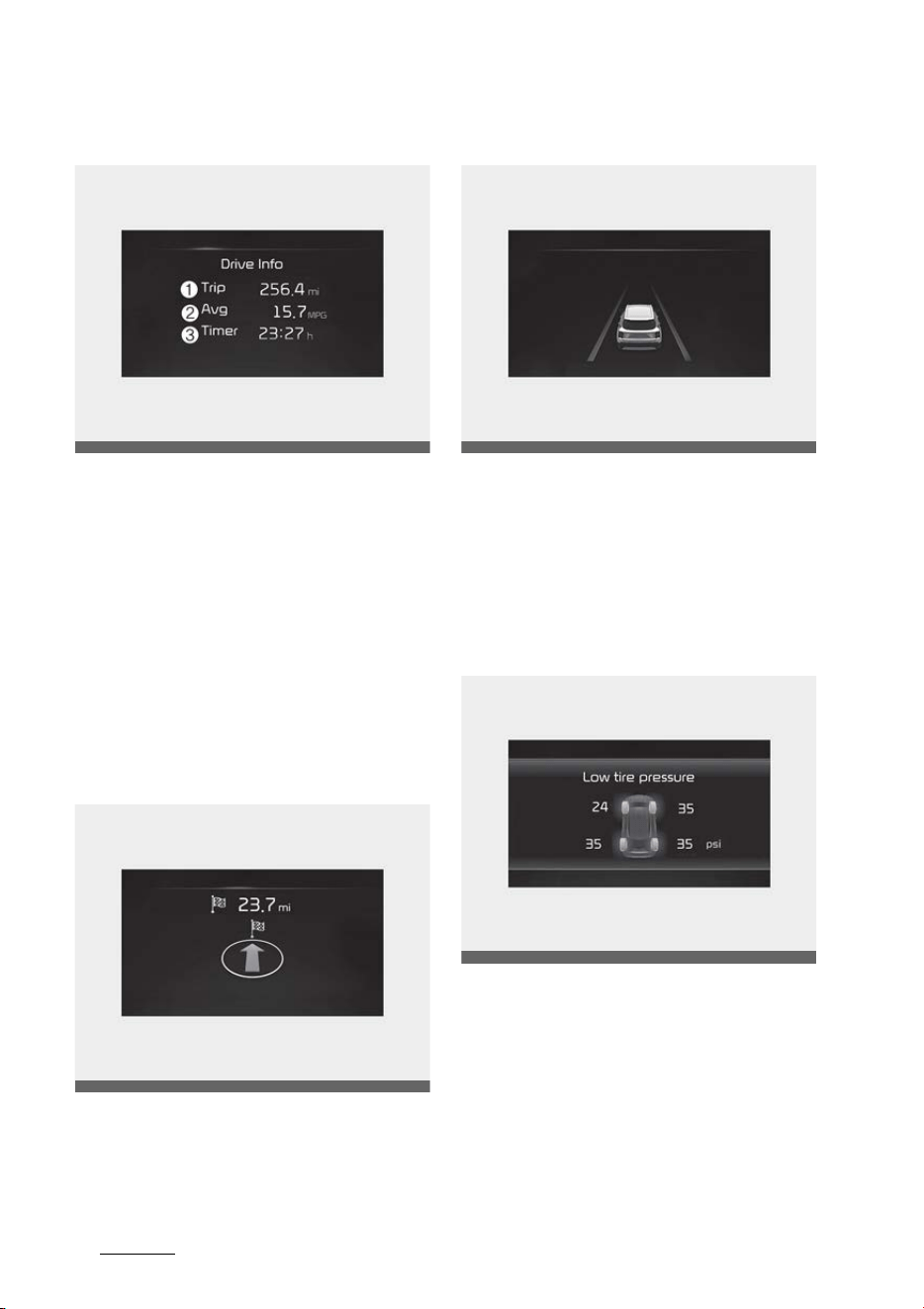
Features of your vehicle
925
LCD display
Trip computer mode
The trip computer mode displays
information related to vehicle driv
-
ing parameters including fuel econ
-
omy, tripmeter information and
timer.
* For more details, refer to "Trip
information (trip computer)" on
page 5-100 and "Hybrid system
overview" on page 1-2.
Turn By Turn (TBT) mode
This mode displays the state of the
navigation.
Driving Assist mode
This mode displays the state of:
䳜 Lane Safety
䳜 Smart Cruise Control
䳜 Driver Attention Warning
䳜 Haptic Warning
Information mode
This mode displays the state of:
䳜 Speedometer
䳜 Engine temperature
䳜 Tire pressure
OMQ4AH040139
OMQ4AH040122
OMQ4050296L
OMQ4040126L
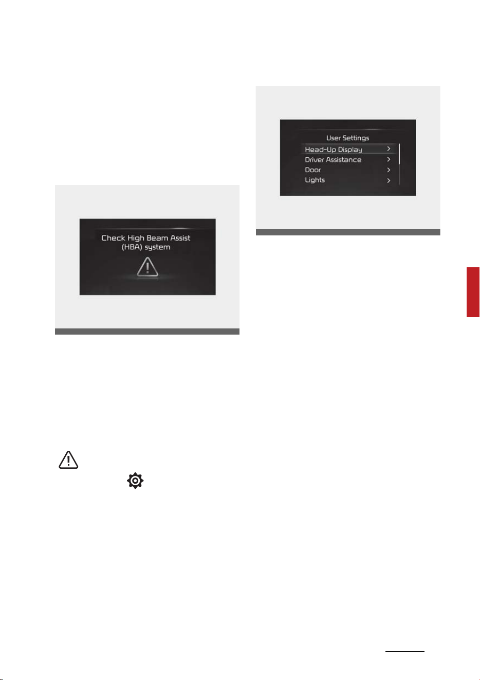
93
5
5
Features of your vehicle LCD display
Tire pressure status
This mode displays information
related to Tire Pressure.
* For more details, refer to "Tire
Pressure Monitoring System
(TPMS)" on page 7-9.
Master warning mode
This warning light informs the driver
the following situations.
䳜 LED headlamp malfunction
䳜 Lamp malfunction
䳜 High Beam Assist malfunction (if
equipped)
At this time, a Master Warning icon
( ) will appear beside the User
Settings icon ( ), on the LCD dis
-
play. If the warning situation is
solved, the master warning light will
be turned off and the Master Warn
-
ing icon will disappear.
User settings mode
In this mode, you can change the
settings of the instrument cluster,
doors, lamps, etc.
1. Head-up Display
2. Driver Assistance
3. Lights
4. Sound
5. Eco Vehicle
6. Door
7. Convenience
8. Service Interval
9. Others
10.Reset
The information provided may dif
-
fer depending on which functions
are applicable to your vehicle.
OMQ4HQ010031L
OMQ4040129L

Features of your vehicle
945
LCD display
1. Head-Up Display (if equipped)
2. Driver Assistance (if equipped)
Items Explanation
Enable Head-up display If this item is checked, Head-Up Display will be activated.
Height
Adjust the height (1~20) of the HUD image on the HUD
screen.
Rotation Adjust the degree (-5~+5) of the HUD rotation.
Brightness Adjust the intensity (1~20) of the HUD brightness.
Contents Selection To select the content information on the HUD screen.
Items Explanation
Driving Convenience
To adjust Highway Driving Assist
* For more details, refer to 䳖"Highway Driving Assist (HDA)
(if equipped)" on page 6-167
Driver Attention Warning
䳜 Leading Vehicle Departure Alert
To select the function.
䳜 Inattentive Driving Warning
To select the function.
* For more details, refer to "Driver Attention Warning
(DAW)" on page 6-127.
Speed Limit Warning
䳜 Speed Limit Offset
To select the Warning time
䳜 Speed Limit Assist/Speed Assist Warning/Off
To select the functions.
* For more details, refer to "Intelligent Speed Limit Assist
(ISLA) (if equipped)" on page 6-122.
Warning Timing
䳜 Normal/Late
To select the warning timing
Warning Volume
䳜 High/Medium/Low/Off
To select the warning volume
Haptic Warning
䳜 Strong/Medium/Light
To select the haptic warning

95
5
5
Features of your vehicle LCD display
* The information provided may differ depending on which systems are
applicable to your vehicle.
Forward Safety
To adjust Forward Collision-Avoidance Assist.
䳜 Active Assist/Warning Only/Off
To select the functions.
* For more details, refer to "Forward Collision-Avoidance
Assist (FCA) (Sensor fusion) (if equipped)" on page 6-73.
Lane Safety
To adjust Lane Keeping Assist.
䳜 Lane Keeping Assist/Lane Departure Warning/Off
To select the functions.
* For more details, refer to "Lane Keeping Assist (LKA)" on
page 6-89.
Blind-Spot Safety
To activate or deactivate Blind-Spot View.
䳜 Blind-Spot View
To activate or deactivate Safe Exit Warning.
䳜 Safe Exit Warning
For more details, refer to "Safe Exit Warning (SEW) (if
equipped)" on page 6-108.
To activate or deactivate Safe Exit Assist.
䳜 Safe Exit Assist
For more details, refer to "Safe Exit Assist (SEA) (if
equipped)" on page 6-112.
䳜 Active Assist/Warning Only/Off
* For more details, refer to "Blind-Spot Collision-Avoidance
Assist (BCA) (if equipped)" on page 6-95.
Parking Safety
䳜 Camera Settings
To adjust the camera settings.
䳜 Surround View Monitor Auto On
䳜 Parking Distance Warning Auto On
䳜 Rear Cross-Traffic Safety
To Activate or deactivate Rear Cross-Traffic Collision-
Avoidance Assist.
䳜 Active Assist/Warning Only/Off
* For more details, refer to "Rear Cross-Traffic Collision-
Avoidance Assist (RCCA) (if equipped)" on page 6-174.
Items Explanation

Features of your vehicle
965
LCD display
3. Door (if equipped)
* The information provided may differ depending on which systems are
applicable to your vehicle.
Items Explanation
Automatically Lock
䳜 Enable on shift (for Automatic transmission): All doors
will be automatically locked if the vehicle is shifted from
the P (Park) position to the R (Reverse), N (Neutral), or D
(Drive) position. (With the Engine ON, it is activated.)
䳜 Enable on speed (for Automatic transmission): All doors
will be automatically locked when the vehicle speed
exceeds 9.3 mph (15 km/h)
䳜 Off: The auto door unlock operation will be canceled.
* If the setting is changed while the vehicle is in motion, the
changed setting may not immediately operate.
Automatically Unlock
䳜 On shift to P (for Automatic transmission): All doors will
be automatically unlocked if the gear is shifted to the P
(Park) position. (With the Engine ON, it is activated.)
䳜 Vehicle Off: All doors will be automatically unlocked
when the ENGINE START/STOP button is set to the OFF
position.
䳜 Off: The auto door unlock operation will be canceled.
2 Press Unlock
If this item is checked, the two press unlock will be acti
-
vated. The driver's door will unlock if the door unlock but
-
ton is pressed. When the door unlock button is pressed
again within 4 seconds, the remaining doors will unlock.
Power Liftgate If this item is checked, Power Liftgate will be activated.
Power Liftgate Speed
䳜 Normal/Fast
To adjust the power liftgate speed.
Power Liftgate Opening
Height
䳜 Level 1/Level 2/Level 3/Full Open/User Height Setting
To select the height.
* For more details, refer to "Power liftgate (if equipped)" on
page 5-32.
Smart Liftgate
To activate or deactivate the Smart Liftgate.
* For more details, refer to "Smart Liftgate with Auto Open
(if equipped)" on page 5-38.

97
5
5
Features of your vehicle LCD display
4. Lights (if equipped)
* The information provided may differ depending on which functions are
applicable to your vehicle.
5. Sound (if equipped)
6. Convenience (if equipped)
Items Explanation
Illumination To adjust the instrument cluster illumination.
One Touch Turn Signal
䳜 Off: The one touch turn signal function will be deacti
-
vated.
䳜 3, 5, 7 flashes: The turn signal indicator will blink 3, 5, or
7 times when the turn signal lever is moved slightly.
* For more details, refer to "Lighting" on page 5-140.
Ambient Light Brightness
䳜 Off/1/2/3/4
To adjust the ambient light brightness.
Ambient Light Color To adjust the ambient light color.
Headlamp Delay
If this item is checked, the headlamp delay function will be
activated.
High Beam Assist If this item is checked, High Beam Assist will be activated.
Items Explanation
Welcome Sound
If this item is checked, the welcome sound function will be
activated.
Items Explanation
Seat (forward/back
-
ward) Easy Access
䳜 Off/Normal/Extended
To select the seat movement
Rear Occupant Alert
If this item is checked, the Rear Occupant Alert (ROA) dis
-
play will be activated.
Welcome Mirror/Light
䳜 On Door Unlock/On Driver Approach
To select the welcome mirror/light function.
Wireless Charging Sys
-
tem
If this item is checked, the wireless charging function will
be activated.
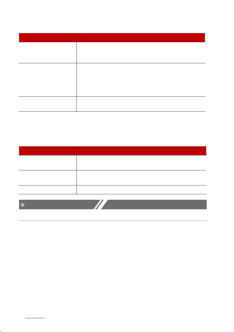
Features of your vehicle
985
LCD display
* The information provided may differ depending on which functions are
applicable to your vehicle.
7. Service interval (if equipped)
NOTICE
To use the service interval menu, consult an authorized Kia dealer.
If the service interval is activated and the time and distance is adjusted,
messages are displayed in the following situations each time the vehicle is
turned on.
䳜 Service in: Displayed to inform the driver the remaining mileage and days
to service.
䳜 Service required: Displayed when the mileage and days to service has
been reached or passed.
If any of the following conditions occur, the mileage and number of days to
service may be incorrect.
䳜 The battery cable is disconnected.
䳜 The battery is discharged.
䳜 The fuse switch is turned off.
Auto Rear Wiper (in R)
If this item is checked, the Auto Rear Wiper will be acti
-
vated when the front wiper is On and the gear is selected
in (R) (Reverse).
Vehicle Auto-Shut Off
䳜 60 min/30 min: To set the vehicle auto-shut off timer
䳜 Disable: The vehicle auto-shut off function will be can
-
celed.
* For more details, refer to "Vehicle Auto Shut-off system
(if equipped)" on page 6-53.
Icy Road Warning
If this item is checked, the icy road warning will be acti
-
vated.
Items Explanation
Items Explanation
Enable Service Interval
If this item is checked, the Service Interval function will be
activated.
Adjust Interval
If the service interval menu is activated, you may adjust
the time and distance.
Reset To reset the service interval function.

99
5
5
Features of your vehicle LCD display
8. Others
* The information provided may differ depending on which functions are
applicable to your vehicle.
9. ECO Vehicle (if equipped)
* The information provided may differ depending on which functions are
applicable to your vehicle.
10. Reset
Items Explanation
Speedometer Unit
䳜 mph, km/h
To select the Speedometer unit.
Fuel Economy Unit
䳜 US gallon, UK gallon
To select the Fuel economy unit.
For more details, refer to "Trip information (trip com
-
puter)" on page 5-100.
Temperature Unit
䳜 F/C
To select the Temperature unit.
Tire Pressure Unit
䳜 psi, kPa, bar
To select the Tire Pressure Unit
Items Explanation
Coasting Guide
䳜 Coasting Guide
To select the function.
䳜 Sound On/Sound Off
To activate or deactivate the sound.
Start Coasting
䳜 Later/Normal/Early
To select the coasting timing.
Items Explanation
Reset
You can reset the menus in the User Settings mode. All
menus in the User Settings mode are reset to factory set
-
tings, except language and service interval.
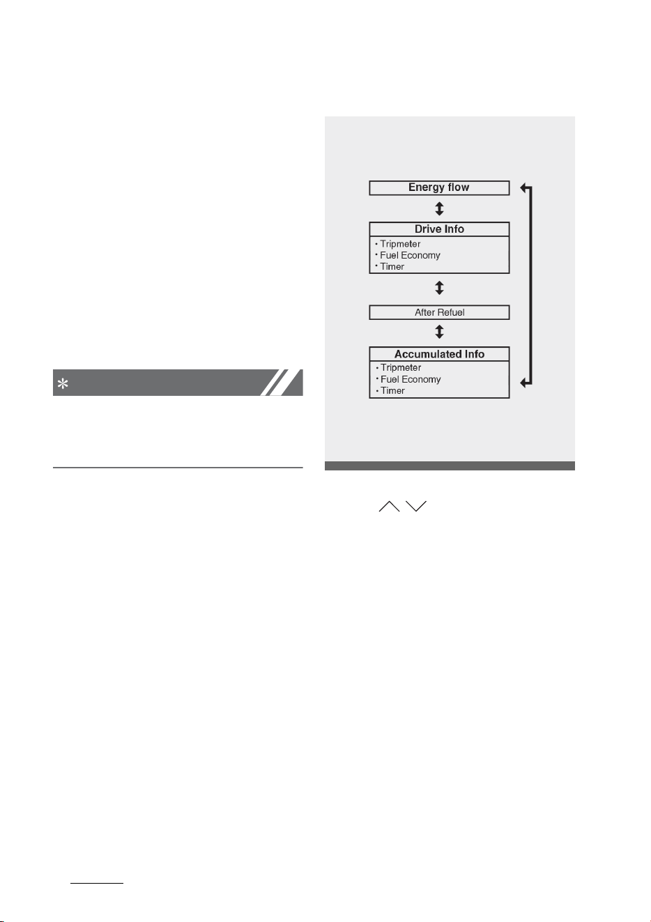
Features of your vehicle
1005
LCD displays
LCD displays
LCD displays show the following
information to drivers.
䳜 Trip information
䳜 LCD modes
䳜 Warning messages
Trip information (trip computer)
The trip computer is a microcom
-
puter- controlled driver information
system that displays information
related to driving.
NOTICE
Some driving information stored in
the trip computer resets if the bat
-
tery is disconnected.
Trip Modes
To change the trip mode, toggle the
switch ( / ) on the steering
wheel.
Fuel economy
This information is always displayed
at the bottom center of the Full LCD
cluster.
OMQ4PH041605L
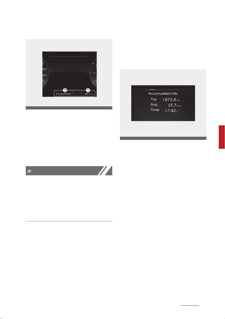
101
5
5
Features of your vehicle LCD displays
Average Fuel Economy (1)
䳜 The average fuel economy is cal
-
culated by the total driving dis
-
tance and fuel consumption since
the last average fuel economy
resets.
- Fuel economy range: 0 ~ 99.9
mpg or km/L, L/100 km
NOTICE
The average fuel economy is not
displayed for more accurate calcula
-
tion if the vehicle does not drive
more than 10 seconds or 0.03 mi
(50 m) since the ENGINE START/
STOP button is turned to ON.
Instant Fuel Economy (2)
䳜 This mode displays the instant
fuel economy during the last few
seconds when the vehicle speed is
more than 6.2 mph (10 km/h).
- Fuel economy range:
0.0~30 km/L, L/100 km or
0.0~50.0 mpg
Accumulated driving information
mode
This display shows the accumulated
trip distance, the average fuel effi
-
ciency, and the total driving time.
䳜 Accumulated information is calcu
-
lated after the vehicle has run for
more than 0.19 miles (300 m).
䳜 If you press "OK" button for more
than 1 second after the Cumula
-
tive Information is displayed, the
information will be reset.
䳜 If the engine is running, even
when the vehicle is not in motion,
the information will be accumu
-
lated.
Drive info display
This display shows the trip distance
(1), the average fuel efficiency (2),
and the total driving time (3) infor
-
mation once per one ignition cycle.
OKA4040530
OMQ4AH040138
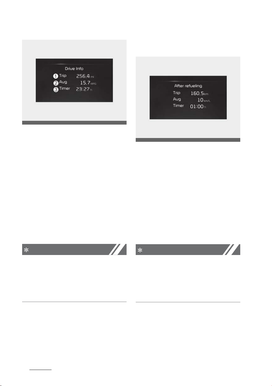
Features of your vehicle
1025
LCD displays
䳜 Fuel efficiency is calculated after
the vehicle has run for more than
0.19 miles (300 m).
䳜 The information will automatically
reset when the driver's door is
opened after the vehicle is turned
off, or approximately 3 minutes
have passed after the vehicle is
turned off.
䳜 If the engine is running, even
when the vehicle is not in motion,
the information will be accumu
-
lated.
NOTICE
The vehicle must be driven for a
minimum of 0.19 miles (300 m)
since the last ignition cycle before
the average accumulated driving
information is recalculated.
Information since refueling
This display shows the trip distance,
the average fuel efficiency, and the
instant fuel efficiency (or the total
driving time) since refueling.
䳜 Information since refueling is cal
-
culated after the vehicle has run
for more than 0.19 miles (300 m).
䳜 If you press "OK" button for more
than 1 second after the informa
-
tion since refueling is displayed,
the information will be reset.
䳜 If the engine is running, even
when the vehicle is not in motion,
the information will be accumu
-
lated.
NOTICE
The vehicle must be driven for a
minimum of 0.19 miles (300 m)
since the last ignition cycle before
the average accumulated driving
information is recalculated.
Range (Plug-in hybrid vehicle)
The range is the estimated distance
the vehicle can be driven with the
remaining high-voltage (hybrid)
OMQ4AH040139
OMQ4A041139L
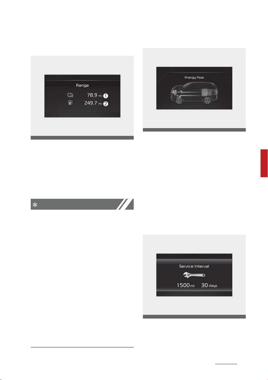
103
5
5
Features of your vehicle LCD displays
battery (1, Electric) and fuel in the
fuel tank (2, Gasoline).
䳜 If the estimated distance is below
1 mile (1 km), the trip computer
will display 䳖---䳗 as distance to
empty.
- Distance range: 1 ~ 510 miles or
1 ~ 510 km.
NOTICE
䳜 If the vehicle is not on level ground
or the battery power has been
interrupted, the range function
may not operate correctly.
䳜 The range may differ from the
actual driving distance as it is an
estimate of the available driving
distance.
䳜 The trip computer may not regis
-
ter additional fuel if less than 1.6
gallons (6 liters) of fuel are added
to the vehicle.
䳜 The range may vary significantly
based on driving conditions, driv
-
ing habits, and condition of the
vehicle.
Energy flow
The hybrid system informs the
driver about its energy flow in vari
-
ous operating modes. While driving,
the current energy flow is specified
in 11 modes.
* For more details, refer to "Energy
flow" on page 1-35.
Service mode
This mode reminds you of scheduled
maintenance information.
OMQ4PH041599L
OMQ4HQ010004L
OMQ4AH040127
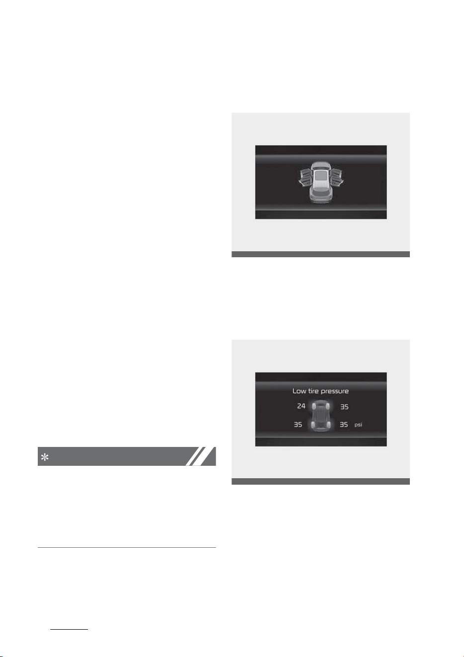
Features of your vehicle
1045
LCD displays
Service Interval
It calculates and displays when you
need a scheduled maintenance ser
-
vice (mileage or days).
If the remaining mileage or time
reaches 900 miles (1,500 km) or 30
days, "Service interval" message is
displayed for several seconds each
time you set the ENGINE START/
STOP button to the ON position.
Service required
If you do not have your vehicle ser
-
viced according to the already
inputted service interval, "Service
required" message is displayed for
several seconds each time you set
the ENGINE START/STOP button to
the ON position.
To reset the service interval to the
mileage and days you inputted
before:
䳜 Press the OK button (Reset) for
more than 1 second.
NOTICE
If any of the following conditions
occurs, the mileage and days may
be incorrect.
䳜 The battery cable is disconnected.
䳜 The battery is discharged.
LCD display messages
Door, hood, liftgate, sunroof open
䳜 This warning is displayed indicat
-
ing which door, the hood, the lift
-
gate or the sunroof is open.
Low pressure warning display
This warning message is displayed if
the tire pressure is low. The corre
-
sponding tire on the vehicle will be
illuminated.
* For more details, refer to "Tire
Pressure Monitoring System
(TPMS)" on page 7-9.
OMQ4040130
OMQ4040126L
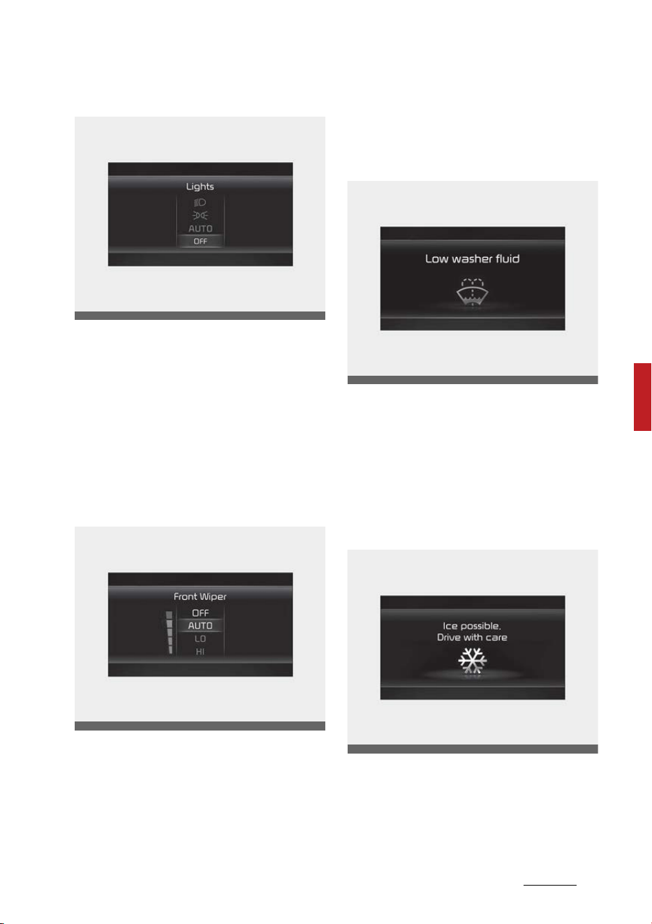
105
5
5
Features of your vehicle LCD displays
Lights mode
This indicator displays which exte
-
rior light is selected using the light
-
ing control.
You can activate or deactivate
Wiper/Lights Display function from
the User Settings mode in the clus
-
ter LCD display.
Wiper mode
This indicator displays which wiper
speed is selected using the wiper
control.
You can activate or deactivate
Wiper/Lights Display function from
the User Settings mode in the clus
-
ter LCD display.
Low washer fluid
This warning message is displayed if
the washer fluid level in the reser
-
voir is nearly empty.
Have the washer fluid reservoir
refilled.
Icy road warning
This warning is to warn the driver
the road may be icy.
When the following conditions occur,
the warning light (including outside
OMQ4AH040161
OMQ4AH040162
OMQ4H040108L
OMQ4040163L

Features of your vehicle
1065
LCD displays
temperature gauge) blinks 5 times
and then illuminates, and also warn
-
ing chime sounds once.
䳜 The temperature on the outside
temperature gauge is below
approximately 40 F (4 C).
NOTICE
If the icy road warning appears
while driving, you should drive more
attentively and safely refraining
from over-speeding, rapid accelera
-
tion, sudden braking or sharp turn
-
ing, etc.
Engine overheated
䳜 This warning message illumi
-
nates when the engine coolant
temperature is above 248 F (120
C). This mean that the engine is
overheated and may be damaged.
* If your vehicle is overheated, refer
to "If the engine overheats" on
page 7-8.
Low key battery
䳜 This warning message illumi
-
nates if the battery of the smart
key is discharged when the
ENGINE START/STOP button
changes to the OFF position.
Press START button while turning
wheel
䳜 This warning message illumi
-
nates if the steering wheel does
not unlock normally when the
ENGINE START/STOP button is
pressed.
䳜 It means that you should press
the ENGINE START/STOP button
while turning the steering wheel
right and left.
Steering wheel unlocked
䳜 This warning message illumi
-
nates if the steering wheel does
not lock when the ENGINE START/
STOP button changes to the OFF
position.
Check steering wheel lock system
䳜 This warning message illumi
-
nates if the steering wheel does
not lock normally when the
ENGINE START/STOP button
changes to the OFF position.
Key not in vehicle
䳜 This warning message illumi
-
nates if the smart key is not in
the vehicle when you press the
ENGINE START/STOP button.
䳜 It means that you should always
have the smart key with you.
Key not detected
䳜 This warning message illumi
-
nates if the smart key is not

107
5
5
Features of your vehicle LCD displays
detected when you press the
ENGINE START/STOP button.
Shift to P or N to start engine
䳜 This warning message illumi
-
nates if you try to start the
engine with the gear not in the P
(Park) or N (Neutral) position.
Press brake pedal to start engine
䳜 This warning message illumi
-
nates if the ENGINE START/STOP
button changes to the ACC posi
-
tion twice by pressing the button
repeatedly without depressing
the brake pedal.
䳜 It means that you should depress
the brake pedal to start the
engine.
Battery discharging due to external
electrical devices
The vehicle can detect self-dis
-
charge of the battery due to over-
current that is generated by unau
-
thorized electrical devices such as
dashboard camera (dash cam)
mounting during parking.
If the warning continues even after
external electrical devices are
removed, have your vehicle
inspected by an authorized Kia
dealer.
Press start button again
䳜 This warning message illumi
-
nates if you can not operate the
ENGINE START/STOP button when
there is a problem with the
ENGINE START/STOP button sys
-
tem.
䳜 It means that you could start the
engine by pressing the ENGINE
START/STOP button once more.
䳜 If the warning illuminates each
time you press the ENGINE
START/STOP button, have the
vehicle inspected by an authorized
Kia dealer.
Press START button with key
䳜 This warning message illumi
-
nates if you press the ENGINE
START/STOP button while the
warning message "Key not
detected" is illuminating.
䳜 At this time, the immobilizer indi
-
cator light blinks.
Check BCW system (if equipped)
This warning message is displayed if
there is a problem with Blind spot
Collision Warning. In this case, have
the vehicle inspected by an autho
-
rized Kia dealer.

Features of your vehicle
1085
LCD displays
Coasting guide (if equipped)
A chime will sound and the coasting
guide indicator will be displayed to
inform the driver when to take the
foot off the accelerator by antici
-
pating a decelerating event* based
on the analysis of driving routes and
road conditions stored in the navi
-
gation system. It encourages the
driver to remove the foot from the
pedal and allow coasting down the
road with EV motor only. This helps
preventing unnecessary fuel con
-
sumption and increases fuel effi
-
ciency.
* Example of a deceleration event is
going down an extended hill, slow
-
ing down approaching a toll booth,
and approaching reduced speed
zones.
䳜 User settings
Press the ENGINE START/STOP
button and put the shift dial in P
(Park). In the User Settings Mode,
select Driver assistance, Coasting
Guide, and then On to turn on the
system. Cancel the selection of
coasting guide to turn off the
system. For the explanation of
the system, press and hold the
[OK] button.
䳜 Operation conditions
To activate the system, take the
following procedures. Enter your
destination information on the
navigation and select the driving
route. Select the ECO mode in the
Integrated Driving Control Sys
-
tem. Then, satisfy the following:
- The driving speed should be
between 19 mph (30 km/h) and
99 mph (160 km/h).
* The operating speed may vary due
to difference between instrument
cluster and navigation effected by
tire inflation level.
Unplug vehicle to start (Plug-in
hybrid vehicle)
The message is displayed when you
start the engine without unplugging
the charging cable. Unplug the
charging cable, and then start the
vehicle.
Remaining Time (Plug-in hybrid
vehicle)
The message is displayed to notify
the remaining time to fully charge
the battery.
OMQ4PH050357L

109
5
5
Features of your vehicle LCD displays
Shift to P to charge (Plug-in hybrid
vehicle)
The message is displayed when the
charging connector is plugged with
the shift dial in R (Reverse), N (Neu
-
tral) or D (Drive). Move the shift dial
to P (Park) and re-start the
charging process.
Electric mode/Automatic mode/
Hybrid mode (Plug-in hybrid vehi
-
cle)
A corresponding message is dis
-
played when a mode is selected by
pressing the HEV button.
Low battery. Maintaining Hybrid
mode (Plug-in hybrid vehicle)
This message is displayed when
unable to convert to EV mode even
when pressing the HEV button
during HEV mode driving due to
insufficient high-voltage (hybrid)
battery level.
Low system temperature. Switch
-
ing to Hybrid mode/ High system
temperature. Switching to Hybrid
mode (Plug-in hybrid vehicle)
This message is displayed when the
temperature of the high-voltage
(hybrid) battery is too low or high.
This warning message is to protect
the battery and the hybrid system.
Low system temperature. Main
-
taining Hybrid mode/ High system
temperature. Maintaining Hybrid
mode (Plug-in hybrid vehicle)
This message is displayed when the
temperature of the high-voltage
(hybrid) battery is too low or too
high. This warning message is to
protect the battery and the hybrid
system.
Wait until fuel door opens (Plug-in
hybrid vehicle)
This message is displayed when you
attempt to open the fuel filler door
with the fuel tank pressurized. Wait
until the fuel tank is depressurized.
Fuel door open (Plug-in hybrid
vehicle)
This message is displayed when the
fuel filler door opens after the fuel
tank is depressurized. If this mes
-
sage is displayed, you can refuel the
fuel tank.
Charging stopped. Check the AC
charger (Plug-in hybrid vehicle)
This messages is displayed when
the charging failed by external char
-
ger error.
The purpose of this message is to
let you know the error has occurred
in the charger itself, not in the vehi
-
cle.

Features of your vehicle
1105
LCD displays
Charging stopped. Check the cable
connection (Plug-in hybrid vehicle)
This messages is displayed when
charging is stopped because the
charging connector is not correctly
connected to the charging inlet. If
this occurs, separate the charging
connector and re-connect it and
check whether there is any problem
(external damage, foreign sub
-
stances, etc.) with the charging con
-
nector and charging inlet. If the
same problem occurs when charging
the vehicle with a replaced charging
cable or genuine Kia portable char
-
ger, have the vehicle inspected by an
authorized Kia dealer.
Charging Door Open (Plug-in hybrid
vehicle)
This message indicates that the
charging door is open while in driv
-
ing- ready state to encourage you
to inspect and close the door.(Driv
-
ing with the charging door open may
result in moisture inflow or damage.
This message is used to prevent
such occurrences.)
Switching to Hybrid mode to allow
heating or air conditioning (Plug-in
hybrid vehicle)
䳜 When the outdoor temperature is
lower than 5 F (-15 C) and the
coolant temperature is lower than
158 F (70 C), you turn the cli
-
mate control On for heating, the
above message will be displayed
in the cluster. Then, the vehicle
will automatically switch to HEV
mode and EV mode will not be
activated (although EV/HEV but
-
ton is pressed)
䳜 When the outdoor temperature is
higher than 14 F (-10 C), or the
coolant temperature is higher
than 176 F (80 C) or you turn
the climate control Off, the vehi
-
cle will automatically return to EV
mode.
Switching to Hybrid mode for self-
diagnosis (Plug-in hybrid vehicle)
This message is displayed for self-
diagnosis of the hybrid mode sys
-
tem.
Low fuel
䳜 This warning message is dis
-
played if the fuel tank is almost
out of fuel.
䳜 When this message is displayed,
the low fuel level warning light in
the cluster will come on.
䳜 It is recommended to look for the
nearest fueling station and refuel
as soon as possible.
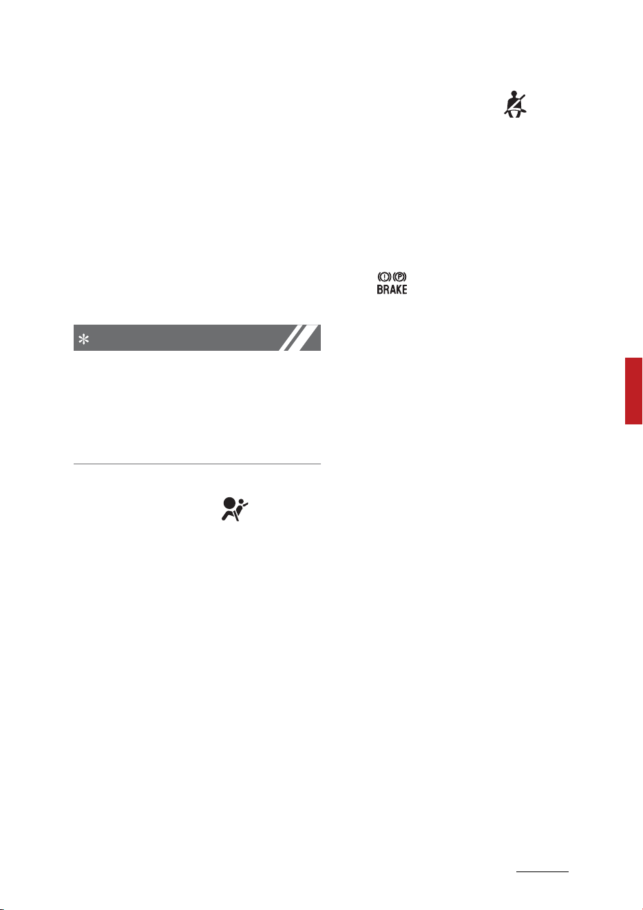
111
5
5
Features of your vehicle Warning and indicator lights
Warning and indicator lights
The warning light and indicator light
indicate a situation where the driver
should be careful and whether the
various functions are activated.
Warning lights
The warning light indicates situa
-
tions that require the driver to pay
attention.
NOTICE
Warning lights
Make sure that all warning lights are
OFF after starting the engine. If any
light is still ON, this indicates a situ
-
ation that needs attention.
Air bag warning light
This warning light illuminates:
䳜 Once you set the ENGINE START/
STOP button to the ON position.
- It illuminates for approximately
3 ~ 6 seconds and then goes off.
䳜 When there is a malfunction with
the SRS.
In this case, have the vehicle
inspected by an authorized Kia
dealer.
Seat belt warning light
This warning light informs the
driver that the seat belt is not fas
-
tened.
* For more details, refer to "Seat
belts" on page 4-24.
Parking brake & brake fluid warning
light
This warning light illuminates:
䳜 Once you set the ENGINE START/
STOP button to the ON position.
- It illuminates for approximately
3 seconds
-It remains on if the parking
brake is applied.
䳜 When the parking brake is applied.
䳜 When the brake fluid level in the
reservoir is low.
- If the warning light illuminates
with the parking brake
released, it indicates the brake
fluid level in reservoir is low.
If the brake fluid level in the reser
-
voir is low:
1. Drive carefully to the nearest safe
location and stop your vehicle.
2. With the engine stopped, check
the brake fluid level immediately
and add fluid as required (For
more details, refer to "Brake fluid"
on page 8-26). Then check all
brake components for fluid leaks.
If any leak on the brake system is
still found, the warning light

Features of your vehicle
1125
Warning and indicator lights
remains on, or the brakes do not
operate properly, do not drive the
vehicle.
In this case, have your vehicle
towed to an authorized Kia dealer
and inspected.
Dual-diagonal braking system
Your vehicle is equipped with dual-
diagonal braking systems. This
means you still have braking on two
wheels even if one of the dual sys
-
tems should fail.
With only one of the dual systems
working, more than normal pedal
travel and greater pedal pressure
are required to stop the vehicle.
Also, the vehicle will not stop in as
short a distance with only a portion
of the brake system working.
If the brakes fail while you are driv
-
ing, shift to a lower gear for addi
-
tional engine braking and stop the
vehicle as soon as it is safe to do so.
NOTICE
Parking brake & brake fluid warning
light
Driving the vehicle with a warning
light ON is dangerous. If the parking
brake & brake fluid warning light
illuminates with the parking brake
released, it indicates that the brake
fluid level is low.
In this case, have your vehicle
inspected by an authorized Kia
dealer.
Anti-lock brake system (ABS)
warning light
This warning light illuminates:
䳜 Once you set the ENGINE START/
STOP button to the ON position.
- It illuminates for approximately
3 seconds and then goes off.
䳜 When there is a malfunction with
the ABS (The normal braking sys
-
tem will still be operational with
-
out the assistance of the anti-
lock brake system).
In this case, have the vehicle
inspected by an authorized Kia
dealer.
Electronic Brake Force Distribution
(EBD) system warning light
These two warning lights illuminate
at the same time while driving:
䳜 When the ABS and regular brake
system are not working, have
your vehicle inspected by an
authorized Kia dealer.
WARNING
Electronic Brake Force Distribution
(EBD) system warning light
When both ABS and parking brake &
brake fluid warning lights are on, the
brake system will not work normally
and you may experience an unex
-
pected and dangerous situation
during sudden braking.

113
5
5
Features of your vehicle Warning and indicator lights
In this case, avoid high speed driving
and abrupt braking.
Have your vehicle inspected by an
authorized Kia dealer as soon as
possible.
Electronic Parking Brake (EPB)
warning light
This warning light illuminates:
䳜 Once you set the ENGINE START/
STOP button to the ON position.
- It illuminates for approximately
3 seconds and then goes off.
䳜 When there is a malfunction with
the EPB.
In this case, have the vehicle
inspected by an authorized Kia
dealer.
NOTICE
Electronic Parking Brake (EPB)
warning light
The Electronic Parking Brake (EPB)
warning light may illuminate when
the Electronic Stability Control (ESC)
indicator light comes on to indicate
that the ESC is not working properly
(This does not indicate malfunction
of the EPB).
All Wheel Drive (AWD) warning light
(if equipped)
This warning light illuminates:
䳜 Once you set the ENGINE START/
STOP button to the ON position.
- It illuminates for approximately
3 seconds and then goes off.
䳜 When there is a malfunction with
the AWD.
In this case, have your vehicle
inspected by an authorized Kia
dealer.
Electric Power Steering (EPS)
warning light
This warning light illuminates:
䳜 Once you set the ENGINE START/
STOP button to the ON position.
-This indicator light comes on
after the ENGINE START/STOP
button is pressed to the ON
position and then goes out
after approximately 3 seconds.
䳜 When there is a malfunction with
the EPS.
In this case, have the vehicle
inspected by an authorized Kia
dealer.
Charging System warning light
This warning light illuminates:
䳜 Once you set the ENGINE START/
STOP button to the ON position.
(3%

Features of your vehicle
1145
Warning and indicator lights
䳜 When there is a malfunction with
either the alternator or electrical
charging system.
If there is a malfunction with either
the alternator or electrical charging
system:
1. Drive carefully to the nearest safe
location and stop your vehicle.
2. Turn the engine off and check the
alternator drive belt for looseness
or breakage.
In this case, have the vehicle
inspected by an authorized Kia
dealer.
Malfunction Indicator Lamp (MIL)
This warning light illuminates:
䳜 When you set the ENGINE START/
STOP button to the ON position.
- The malfunction indicator light
illuminates for about 3 seconds
and then goes off.
䳜 Whenever there is a malfunction
with either the emission control
system or the engine or the vehi
-
cle powertrain.
If this occurs, have the vehicle
inspected by an authorized Kia
dealer.
CAUTION
Malfunction Indicator Lamp (MIL)
䳜 Driving with the Malfunction Indi
-
cator Lamp (MIL) on may cause
damage to the emission control
systems which could effect driv
-
ability and/or fuel economy.
䳜 If the enhanced engine protection
system becomes activated due to
lack of engine oil, engine power
will be limited. If such condition
continues repeatedly, the Mal
-
function Indicator Lamp will illu
-
minate.
CAUTION
If the Malfunction Indicator Lamp
(MIL) illuminates, potential catalytic
converter damage is possible which
could result in loss of engine power.
In this case, have the vehicle
inspected by an authorized Kia
dealer.
Engine oil pressure warning light
This warning light illuminates:
䳜 Once you set the ENGINE START/
STOP button to the ON position.
- It remains on until the engine is
started.
䳜 When the engine oil pressure is
low.
If the engine oil pressure is low:
䳜 Drive carefully to the nearest safe
location and stop your vehicle.
䳜 Turn the engine off and check the
engine oil level (For more details,
115
5
5
Features of your vehicle Warning and indicator lights
refer to "Engine oil and filter" on
page 8-16). If the level is low, add
oil as required.
䳜 If the warning light remains on
after adding oil or if oil is not
available, have the vehicle
inspected by an authorized Kia
dealer. Continued driving with the
warning light on may cause
engine failure.
NOTICE
䳜 When engine oil pressure
decreases due to insufficient
engine oil, etc., the Engine Oil
Pressure warning light will illumi
-
nate.
䳜 The enhanced engine protection
system which limits engine power
will be activated. If the engine oil
pressure is restored, the Engine
Oil Pressure warning light and the
enhanced engine protection sys
-
tem will turn off.
CAUTION
Engine overheating
Do not continue driving with the
engine overheated. Otherwise, the
engine may be damaged.
CAUTION
Engine damage
If the engine is not stopped immedi
-
ately after the engine oil pressure
warning light is illuminated and
stays on while the engine is running,
serious engine damage may result.
Ready indicator
This indicator illuminates:
When the vehicle is ready to be
driven.
䳜 ON: Normal driving is possible.
䳜 OFF: Normal driving is not possi
-
ble, or a problem has occurred.
EV mode indicator
This indicator illuminates:
When the vehicle is driven by the
electric motor.
䳜 "EV" indicator ON : Vehicle is
driven using the electric motor or
the gasoline engine is stopped.
䳜 "EV" indicator OFF : Vehicle is
driven using the gasoline engine.
Features of your vehicle
1165
Warning and indicator lights
Service warning light
This warning light illuminates:
䳜 When you set the ENGINE START/
STOP button to the ON position.
- The service warning light illumi
-
nates for approximately 3 sec
-
onds and then turns off when
all checks have been performed.
䳜 When there is a problem with the
hybrid vehicle control system or
hardware.
When the warning light illuminates
while driving, or does not go OFF
after starting the vehicle, have the
vehicle inspected by an authorized
Kia dealer.
Regenerative brake warning light
(red color) (yellow color)
This warning light illuminates:
When the regenerative brake does
not operate and the brake does not
perform well. This causes the Brake
Warning light (red) and Regenera
-
tive Brake Warning Light (yellow) to
illuminate simultaneously.
If this occurs, drive safely and have
your vehicle inspected by an autho
-
rized Kia dealer. The operation of
the brake pedal may be more diffi
-
cult than normal and the braking
distance may increase.
Low fuel level warning light
This warning light illuminates:
When the fuel tank is nearly empty.
If the fuel tank is nearly empty:
Add fuel as soon as possible.
CAUTION
Low fuel level
Driving with the low fuel level warn
-
ing light on or with the fuel level
below "E" can cause the engine to
misfire and damage the catalytic
converter.
Master warning light
This indicator light illuminates:
䳜 This warning light informs the
driver the following situations
- LED headlamp malfunction (if
equipped)
- Lamp malfunction
- High Beam Assist malfunction
(if equipped)
To identify the details of the warn
-
ing look at the LCD display.
If the warning situation is solved,
the master warning light will turn
off.
117
5
5
Features of your vehicle Warning and indicator lights
Low tire pressure warning light
This warning light illuminates:
䳜 Once you set the ENGINE START/
STOP button to the ON position.
- It illuminates for approximately
3 seconds and then goes off.
䳜 When one or more of your tires
are significantly under inflated.
(The location of the underinflated
tires are displayed on the LCD dis
-
play).
* For more details, refer to "Tire
Pressure Monitoring System
(TPMS)" on page 7-9.
This warning light remains on after
blinking for approximately 60 sec
-
onds or repeats blinking on and off
at the intervals of approximately 3
seconds:
䳜 When there is a malfunction with
the TPMS.
In this case, have the vehicle
inspected by an authorized Kia
dealer.
* For more details, refer to "Tire
Pressure Monitoring System
(TPMS)" on page 7-9.
WARNING
Low tire pressure
䳜 Significantly low tire pressure
makes the vehicle unstable and
can contribute to loss of vehicle
control and increased braking dis
-
tances.
䳜 Continued driving or low pressure
tires will cause the tires to over
-
heat and fail.
WARNING
Safe stopping
䳜 The TPMS cannot alert you to
severe and sudden tire damage
caused by external factors.
䳜 If you notice any vehicle instabil
-
ity, immediately take your foot
off the accelerator pedal, apply
the brakes gradually with light
force, and slowly move to a safe
position off the road.
LED headlamp warning light
This warning light illuminates:
䳜 Once you set the ENGINE START/
STOP button to the ON position.
- It illuminates for approximately
3 seconds and then goes off.
䳜 When there is a malfunction with
the LED headlamp.
In this case, have the vehicle
inspected by an authorized Kia
dealer.
This warning light blinks:
䳜 When there is a malfunction with
a LED headlamp related part.
In this case, have the vehicle
inspected by an authorized Kia
dealer.
Features of your vehicle
1185
Warning and indicator lights
CAUTION
LED headlamp warning light
Continuous driving with the LED
headlamp warning light on or blink
-
ing can reduce LED headlamp (low
beam) life.
Forward Safety warning light
(if equipped)
This indicator light illuminates:
䳜 When there is a malfunction with
Forward Collision-Avoidance
Assist.
In this case, have the vehicle
inspected by an authorized Kia
dealer.
Icy road warning light (if
equipped)
This indicator light illuminates:
This warning light is to warn the
driver the road may be icy. When
the temperature on the outside
temperature gauge is approxi
-
mately below 39 F (4 C), the icy
road warning light and outside tem
-
perature gauge blinks and then illu
-
minates. Also, the warning chime
sounds 1 time.
Indicator lights
Charging cable connection indicator
light (Plug-in hybrid vehicle)
This indicator illuminates in red
when the charging cable is con
-
nected.
Electronic Stability Control (ESC)
indicator light
This indicator light illuminates:
䳜 Once you set the ENGINE START/
STOP button to the ON position.
- It illuminates for approximately
3 seconds and then goes off.
䳜 When there is a malfunction with
the ESC system.
In this case, have the vehicle
inspected by an authorized Kia
dealer.
This indicator light blinks:
While the ESC is operating.
* For more details, refer to "Elec
-
tronic Parking Brake (EPB)" on
page 6-34.
Electronic Stability Control (ESC)
OFF indicator light
This indicator light illuminates:
䳜 Once you set the ENGINE START/
STOP button to the ON position.
- It illuminates for approximately
3 seconds and then goes off.

119
5
5
Features of your vehicle Warning and indicator lights
䳜 When you deactivate the ESC
system by pressing the ESC OFF
button.
* For more details, refer to "Elec
-
tronic Stability Control (ESC) sys
-
tem" on page 6-44.
AUTO HOLD indicator light (AUTO
HOLD)
This indicator light illuminates:
䳜 White When you activate the auto
hold system by pressing the
AUTO HOLD button.
䳜 Green When you stop the vehicle
completely by depressing the
brake pedal with the auto hold
system activated.
䳜 Yellow When there is a malfunc
-
tion with the auto hold system. In
this case, have the vehicle
inspected by an authorized Kia
dealer.
* For more details, refer to "AUTO
HOLD" on page 6-39.
Immobilizer indicator light (with
smart key)
This indicator light illuminates for
up to 30 seconds:
䳜 When the vehicle detects the
smart key in the vehicle properly
while the ENGINE START/STOP
button is ACC or ON.
- At this time, you can start the
engine.
- The indicator light goes off
after starting the engine.
This indicator light blinks for a few
seconds:
䳜 When the smart key is not in the
vehicle.
- At this time, you can not start
the engine.
This indicator light illuminates for 2
seconds and goes off:
䳜 When the vehicle can not detect
the smart key which is in the
vehicle while the ENGINE START/
STOP button is ON.
In this case, have the vehicle
inspected by an authorized Kia
dealer.
This indicator light blinks:
䳜 When the battery of the smart
key is weak.
- At this time, you can not start
the engine. However, you can
start the engine if you press
the ENGINE START/STOP
button with the smart key. (For
more details, refer to "Immobi
-
lizer system" on page 5-13).
䳜 When there is a malfunction with
the immobilizer system.
In this case, have the vehicle
inspected by an authorized Kia
dealer.

Features of your vehicle
1205
Warning and indicator lights
Turn signal indicator light
This indicator light blinks:
䳜 When you turn the turn signal
light on.
If any of the following occurs, there
may a malfunction with the turn
signal system. In this case, have the
vehicle inspected by an authorized
Kia dealer.
䳜 The indicator light does not blink
but illuminates.
䳜 The indicator light blinks more
rapidly.
䳜 The indicator light does not illumi
-
nate at all.
Low beam indicator light
This indicator light illuminates:
䳜 When the headlamps are on.
High beam indicator light
This indicator light illuminates:
䳜 When the headlamps are on and
in the high beam position.
䳜 When the turn signal lever is
pulled into the Flash-to-Pass
position.
High Beam Assist indicator light
(if equipped)
This indicator light illuminates:
䳜 When the high beam is on with
the light switch in the AUTO light
position.
䳜 If your vehicle detects oncoming
or preceding vehicles, High Beam
Assist will switch the high beam
to low beam automatically.
* For more details, refer to "High
Beam Assist (HBA)" on page 5-
144.
Light ON indicator light
This indicator light illuminates:
䳜 When the taillamps or headlamps
are on.
Front fog indicator light (if
equipped)
This indicator light illuminates:
䳜 When the front fog lights are on.
Lane Safety indicator (if
equipped)
Lane Safety indicator will illuminate
when you turn Lane Keeping Assist
on by pressing Lane Safety button.
If there is a problem with Lane
Keeping Assist, the yellow Lane
Safety indicator will illuminate.
* For more details, refer to "Lane
Keeping Assist (LKA)" on page 6-
89.
121
5
5
Features of your vehicle Warning and indicator lights
Cruise Control indicator light (if
equipped)
This indicator light illuminates:
䳜 When the cruise control system is
enabled.
* For more details, refer to "Cruise
Control (CC) (if equipped)" on page
6-136.
Downhill Brake Control (DBC) indi
-
cator light
This indicator light illuminates:
䳜 When you set the ENGINE START/
STOP button to the ON position.
- It illuminates for approximately
3 seconds and then goes off.
䳜 When you activate the system by
pressing the DBC button.
This indicator light blinks:
䳜 When the DBC is operating.
This indicator light illuminates yel
-
low:
䳜 When there is a malfunction with
the DBC system.
If this occurs, have your vehicle
inspected by an authorized Kia
dealer.
* For more details, refer to "Downhill
Brake Control (DBC)" on page 6-
47.
All Wheel Drive (AWD) LOCK indica
-
tor light (if equipped)
This warning light illuminates:
䳜 Once you set the ENGINE START/
STOP button to the ON position.
- It illuminates for approximately
3 seconds and then goes off.
䳜 When you select AWD lock mode
by pressing the AWD LOCK button.
- The AWD lock mode is to
increase the drive power when
driving on wet pavement, snow
covered roads and/or off-road.
NOTICE
AWD lock mode
Do not use AWD LOCK mode on dry
paved roads or highway, it can
cause noise, vibration or damage of
AWD related parts.
SPORT Mode indicator light
This indicator light illuminates :
䳜 When you select "SPORT" mode
as drive mode.
For more details, refer to "Drive
mode integrated control system" on
page 6-55.
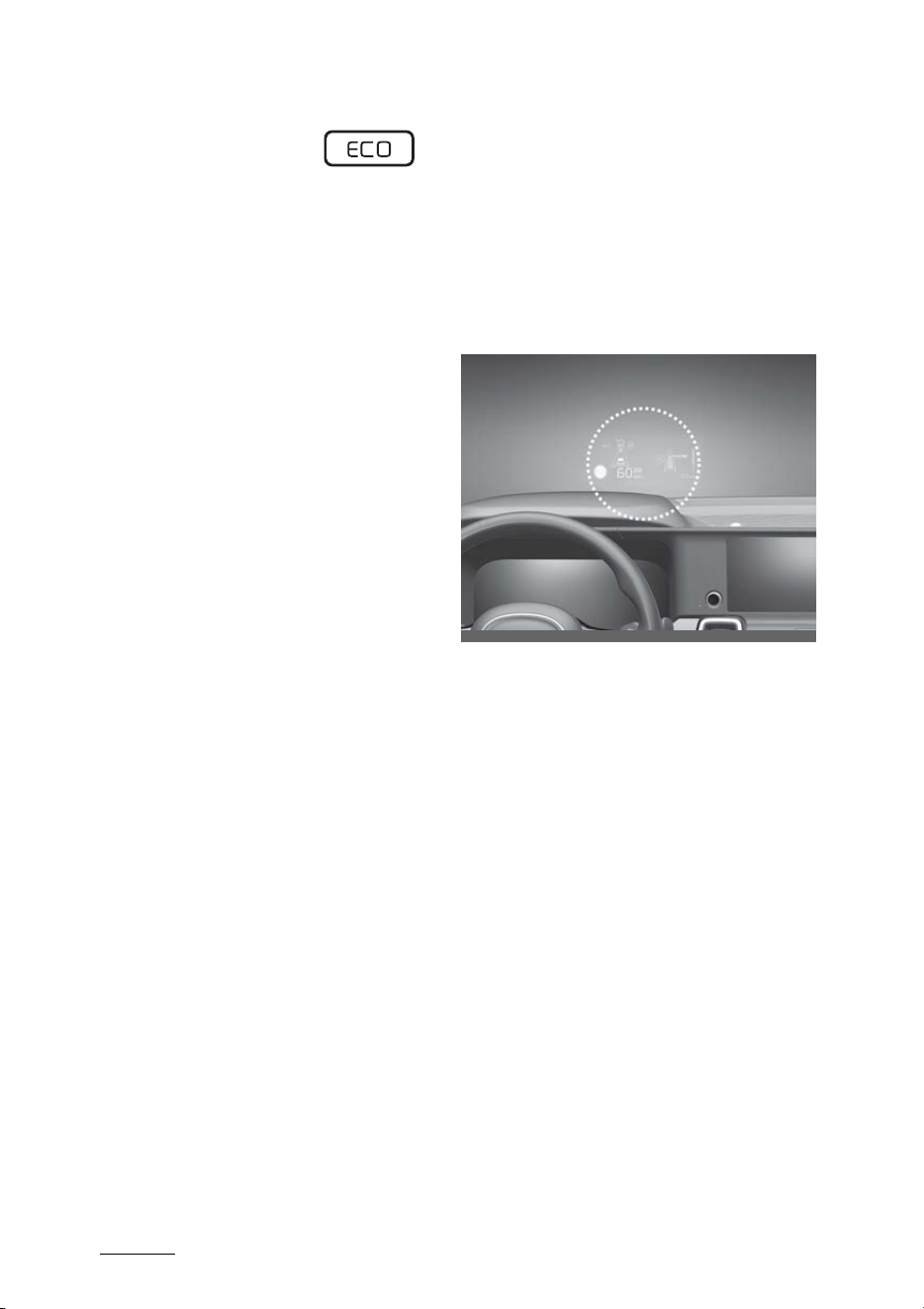
Features of your vehicle
1225
Head-Up Display (HUD)
ECO Mode indicator light
This indicator light illuminates:
䳜 When you select "ECO" mode as
drive mode.
For more details, refer to "Drive
mode integrated control system" on
page 6-55.
Head-Up Display (HUD) (if
equipped)
The Head-Up Display is a transpar
-
ent display that projects an image
of certain information from the
instrument cluster and navigation
system on the windshield glass.
䳜 The head up display image on the
HUD screen may be invisible
when:
- Sitting posture is bad.
- Wearing a polarized sunglasses.
- There is an object on the cover
of the head up display.
- Driving on a wet road.
- An inadequate lighting is turned
on inside the vehicle.
- Any light comes from the out
-
side.
- Wearing an inadequate glasses
to your eyesight.
䳜 If the head up display image is not
shown well, adjust the height,
rotation or illumination of the
head up display in the LCD display.
OMQ4AH040038
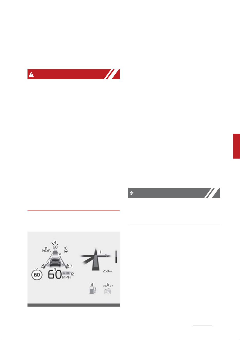
123
5
5
Features of your vehicle Head-Up Display (HUD)
䳜 When the Head-Up Display needs
inspection or repair, have your
vehicle inspected or repaired by
an authorized Kia dealer.
WARNING
Head-Up Display
䳜 Do not make the front windshield
glass have window tint or other
types of metallic coating. Other
-
wise, the Head-Up Display image
may be invisible.
䳜 Do not place any accessories on
the crash pad or attach any
objects on the windshield glass.
䳜 As Blind-Spot Collision Warning is
a supplemental device for your
safe driving, it may be dangerous
to rely on only the BCW informa
-
tion of the Head-Up Display
image when changing the lane.
Always pay attention to drive
safely.
Head-Up Display Information
1. Turn By Turn navigation informa
-
tion (if equipped)
2. Road signs
3. Speedometer
4. SCC setting speed information (if
equipped)
5. SCC vehicle distance information
(if equipped)
6. Lane Safety information (if
equipped)
7. Blind-Spot Safety information (if
equipped)
8. Warning lights (Low fuel)
9. AV mode information
10.Lane Following Assist informa
-
tion (if equipped)
11.Highway Driving Assist informa
-
tion (if equipped)
12.Navigation-based Smart Cruise
Control information (if equipped)
NOTICE
Road Signs and Turn By Turn navi
-
gation information are available
depending on the region.
Head-Up Display Setting
On the LCD display, you can change
the head up display settings as fol
-
lows.
1. Display height
2. Rotation
3. Brightness
4. Content selection
* For more details, refer to "LCD dis
-
play modes" on page 5-91.
OMQ4A040449MX
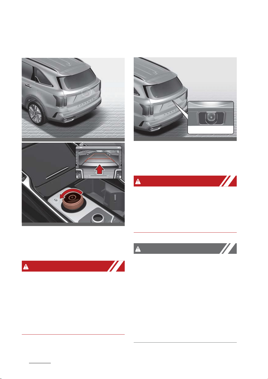
Features of your vehicle
1245
Rear View Monitor (RVM)
Rear View Monitor (RVM) (if
equipped)
Rear View Monitor will show the
area behind the vehicle to assist you
when parking or backing up.
WARNING
The outside rear view camera does
not cover the complete area behind
the vehicle. The driver should
always check the rear area directly
through the rear view mirror and
side view mirrors before parking or
backing up.
Detecting sensor
Rear view camera
Refer to the picture above for the
detailed location of the detecting
sensor.
WARNING
The image shown on the screen
may differ from the actual distance
of the object. Make sure to directly
check the vehicle's surroundings for
safety.
CAUTION
If the camera lens is covered with
foreign material, Rear View Monitor
may not operate normally. Always
keep the camera lens clean.
However, do not use chemical sol
-
vents such as strong detergents
containing high alkaline or volatile
organic solvents (gasoline, acetone
etc.). This may damage the camera
lens.
OMQ4AH041564
OMQ4040040L
OMQ4AH041489
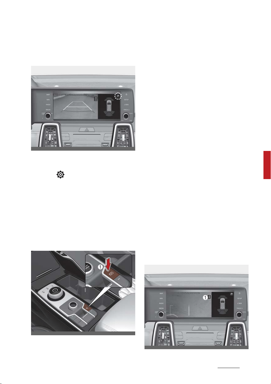
125
5
5
Features of your vehicle Rear View Monitor (RVM)
Rear View Monitor Settings
Setting
䳜 You can change Rear View Moni
-
tor settings by pressing the setup
icon 「 」 on the screen while
the function is operating, or select
'Driver Assistance → Parking
Safety → Camera Settings' from
the Settings menu while the
ENGINE START/STOP button is in
the ON position.
Parking/View button
Press the Parking/View button (1)
to turn Rear View Monitor on or off.
Rear View Monitor Operation
Rear view with parking guidance
The function will operate when the
following conditions are satisfied:
䳜 ENGINE START/STOP button in
the ON position
䳜 The gear is changed to R
(Reverse) and the back up light
turns on
Extended Rear View Monitor
䳜 When parking, the rear view will
maintain showing on the screen if
the following conditions are satis
-
fied:
- The gear is changed from R
(Reverse) to N (Neutral) or D
(Drive)
- Vehicle speed is below 6 mph
(10 km/h)
䳜 The rear view will turn off when
vehicle speed is above 6 mph (10
km/h).
Rear top view
OMQ4AH050163
OMQ4H040004
OMQ4AH040467
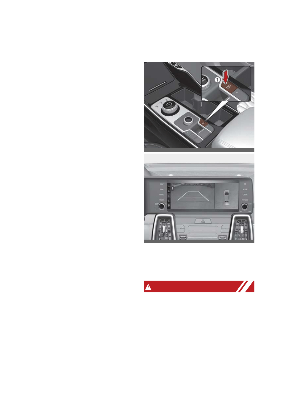
Features of your vehicle
1265
Surround View Monitor (SVM)
When you touch the icon (1), the top
view is displayed on the screen and
shows the distance from the vehicle
in the back of your vehicle while
parking.
Rear View Monitor Malfunction and
Limitations
Rear View Monitor malfunction
When Rear View Monitor is not
working properly, or the screen
flickers, or the camera image does
not display normally, have the func
-
tion be inspected by an authorized
Kia dealer.
Limitations of Rear View Monitor
When the vehicle is stopped for a
long time in winter or when the
vehicle is parked in an indoor parking
lot, the exhaust fumes may tempo
-
rarily blur the image.
Surround View Monitor (SVM) (if
equipped)
Surround View Monitor will assist in
parking by allowing the driver to see
around the vehicle.
WARNING
ALWAYS look around your vehicle to
make sure there are no objects or
obstacles before moving the vehicle.
What you see on the screen may
differ from the actual vehicle's loca
-
tion.
OMQ4H040004
OMQ4041468L
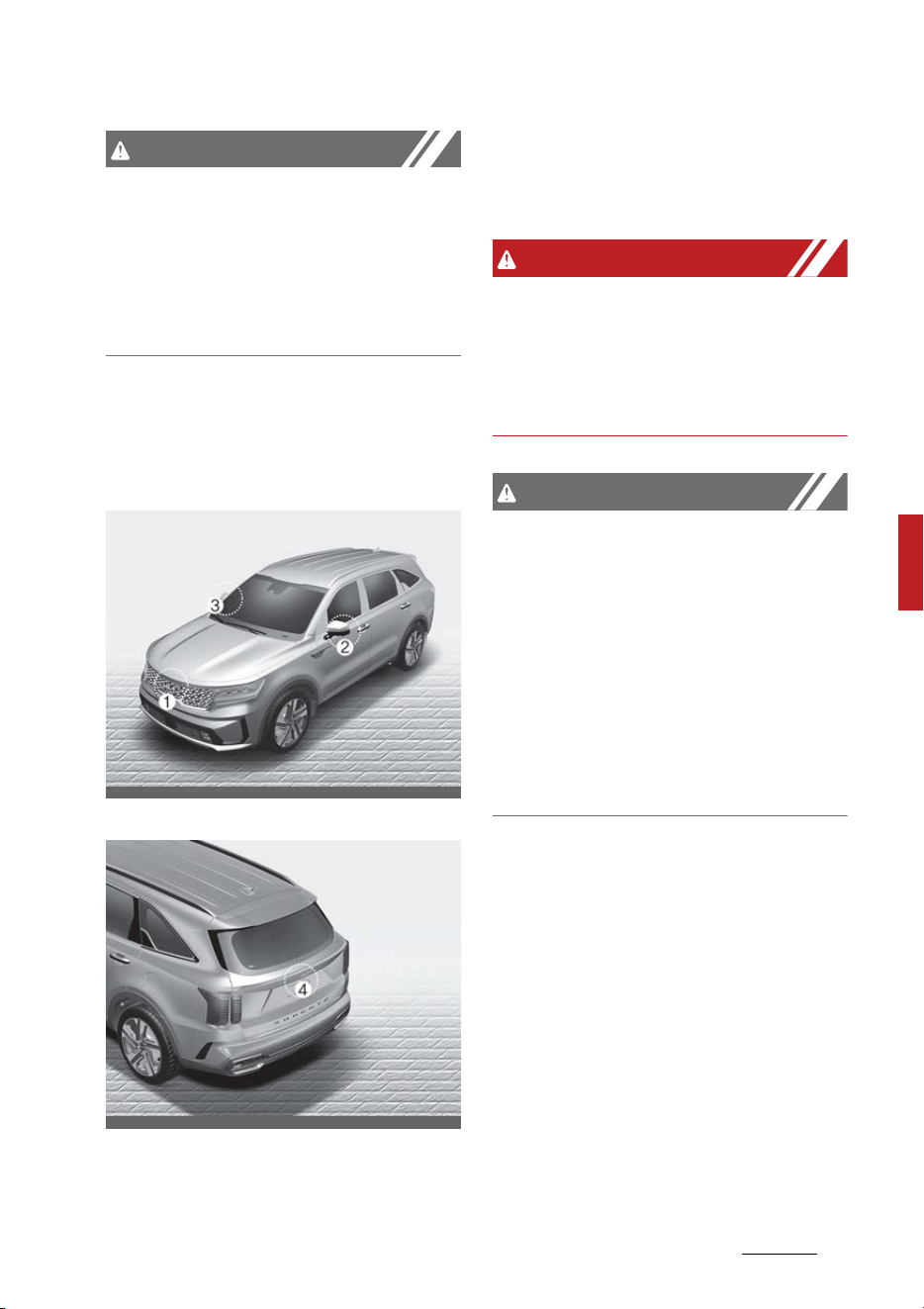
127
5
5
Features of your vehicle Surround View Monitor (SVM)
CAUTION
Surround View Monitor is designed
to be used on a flat surface. There
-
fore, if used on roads with different
heights such as curbs and speed
bumps, the image in the screen may
not look correct.
Detecting sensor
SVM-front view camera, SVM-side view
camera (under the outside rear view
mirror)
SVM-rear view camera
Refer to the picture above for the
detailed location of the detecting
sensors.
WARNING
The image shown on the screen
may differ from the actual distance
of the object. Make sure to directly
check the vehicle's surroundings for
safety.
CAUTION
If the camera lens is covered with
foreign material, the Surround View
Monitor may not operate normally.
Always keep the camera lens clean.
However, do not use chemical sol
-
vents such as strong detergents
containing high alkaline or volatile
organic solvents (gasoline, acetone
etc.). This may damage the camera
lens.
OMQ4H041010
OMQ4AH041565
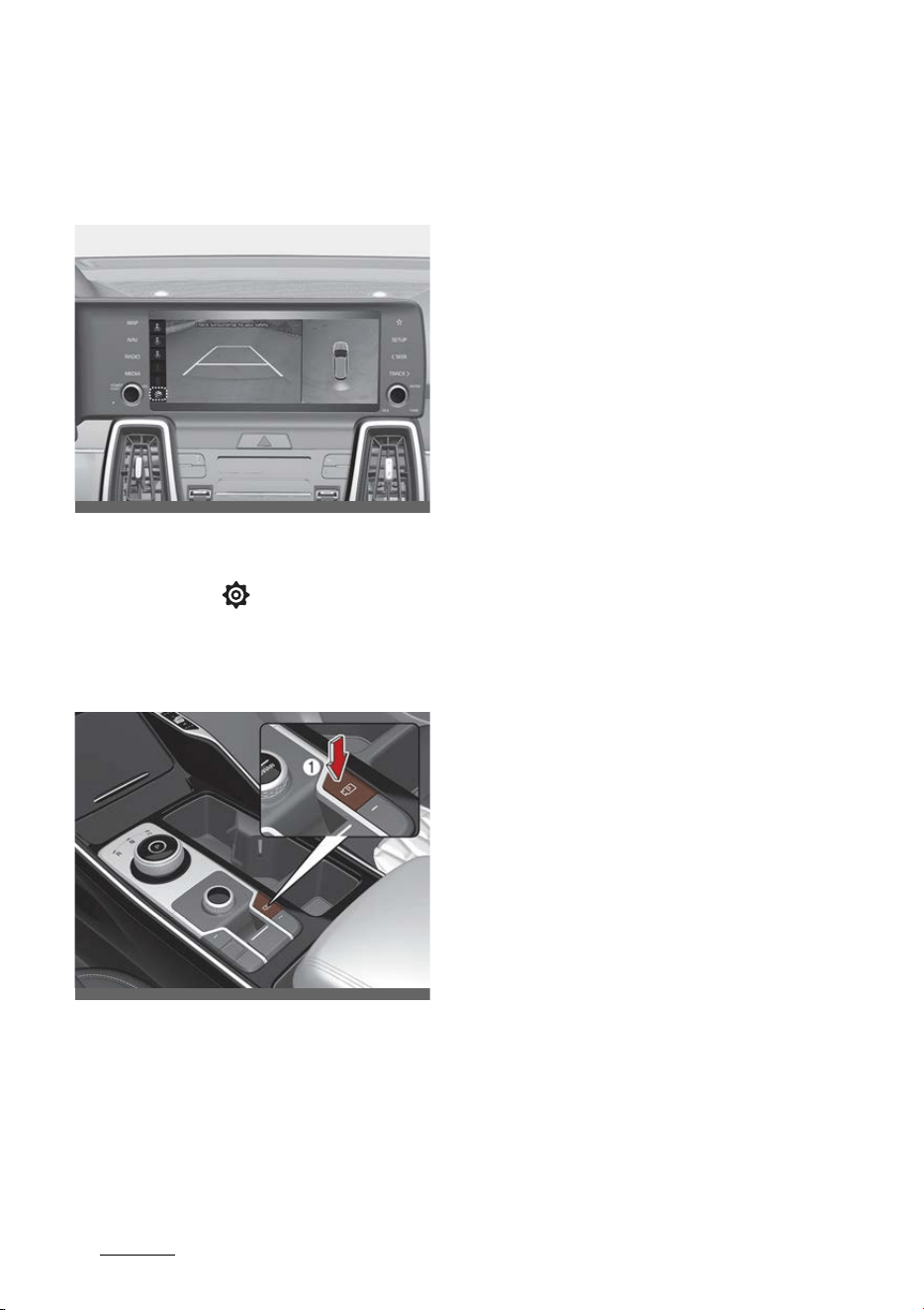
Features of your vehicle
1285
Surround View Monitor (SVM)
Surround View Monitor Settings
Setting
䳜 You can change Surround View
Monitor settings by pressing the
setup icon 「 」 on the screen
while the function is operating.
Parking/View button
Press the Parking/View button (1)
to turn Rear View Monitor on or off.
Press the button again to turn off
the function.
Surround View Monitor Operation
Parking assist view
Operating Conditions
䳜 The function will operate when
the following conditions are satis
-
fied:
- The gear is changed to R
(Reverse)
- The gear is changed from R
(Reverse) to N (Neutral) or D
(Drive) when vehicle speed is
below 9 mph (15 km/h)
- Parking/View button is pressed
with the gear in D (Drive) or N
(Neutral) when vehicle speed is
below 9 mph (15 km/h)
- Parking/View button is pressed
with the gear in P (Parking)
- Parking Distance Warning
warns the driver when the gear
is in D (Drive)
However, 'Driver Assistance →
Parking Safety → Surround
View Monitor Auto On' must be
selected from the Settings
menu.
䳜 An indicator on the screen
appears when:
- The liftgate is opened
- The driver or front passenger
door is opened
- The outside rear view mirror is
folded
䳜 Driving rear view operates
regardless of vehicle speed when
OMQ4AH040450
OMQ4H040004

129
5
5
Features of your vehicle Surround View Monitor (SVM)
the gear is in D (Drive) or N (Neu
-
tral). Refer to "Driving rear view"
in the following pages.
䳜 Other view modes can be selected
by touching the view icons on the
Surround View Monitor screen.
Off Conditions
䳜 Parking/View button is repressed.
䳜 When vehicle speed is above 9
mph (15 km/h), Surround View
Monitor will turn off and the
screen will change back to the
previous infotainment system
screen.
䳜 When the gear is in R (Reverse),
Surround View Monitor will turn
ON regardless of vehicle speed or
button status. However, if vehicle
speed is above 9 mph (15 km/h)
with the gear in D (Drive), the
function will turn off.
䳜 One of the infotainment system
buttons is pressed without the
gear in R (Reverse). The screen
will change back to the previous
infotainment system screen.
Surround View Monitor Malfunction
and Limitations
Surround View Monitor malfunction
When Surround View Monitor is not
working properly, or the screen
flickers, or the camera image does
not display normally, have the func
-
tion be inspected by an authorized
Kia dealer.
Limitations of Surround View Moni
-
tor
When the vehicle is stopped for a
long time in winter or when the
vehicle is parked in an indoor parking
lot, the exhaust fumes may tempo
-
rarily blur the image.
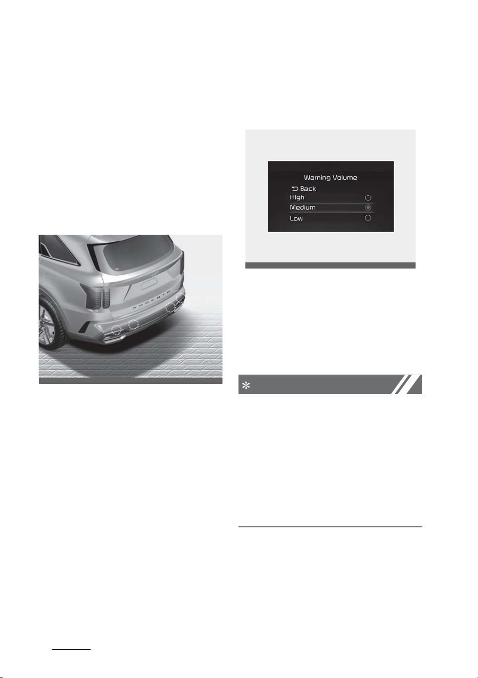
Features of your vehicle
1305
Reverse Parking Distance Warning (PDW)
Reverse Parking Distance Warn
-
ing (PDW) (if equipped)
Reverse Parking Distance Warning
will help warn the driver if a person,
an animal or an object is detected
within a certain distance when the
vehicle is moving in reverse.
Detecting sensor
Rear ultrasonic sensors
Refer to the picture above for the
detailed location of the detecting
sensors.
Reverse Parking Distance Warning
Settings
Warning Volume
Select 'Settings → Driver Assistance
→ Warning Volume' from cluster or
infotainment system to change the
Warning Volume to 'High', 'Medium',
'Low' or 'Off' for Reverse Parking
Distance Warning.
NOTICE
䳜
If you change the Warning Vol
-
ume, the warning volume of other
Driver Assistance systems may
change.
䳜
Even if 'Off' is selected, the Warn
-
ing Volume of Reverse Parking
Distance Warning will not turn off
but the volume will sound as
'Low'.
Parking Distance Warning Auto On
You can set the Parking Distance
Waring to be ON at low speeds. To
use Parking Distance Warning Auto
On function, select 'Settings →
OMQ4AH041566
OMQ4041606
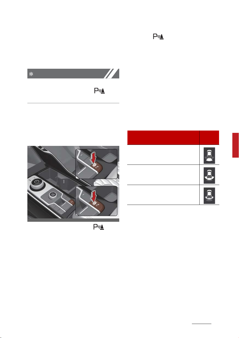
131
5
5
Features of your vehicle Reverse Parking Distance Warning (PDW)
Driver Assistance → Parking Safety
→ Parking Distance Warning Auto
On' from the infotainment system
with the Engine ON.
NOTICE
If Parking Distance Warning Auto On is
selected, the Parking Safety ( ) but
-
ton indicator light will turn on.
Reverse Parking Distance Warning
Operation
Parking Safety button (if equipped)
Press the Parking Safety ( ) but
-
ton to turn on or off Reverse Park
-
ing Distance Warning.
䳜 When Reverse Parking Distance
Warning is off (button indicator
light off), if you shift the gear to R
(Reverse), Reverse Parking Dis
-
tance Warning will automatically
turn on.
䳜 If you shift the gear to R
(Reverse), Reverse Parking Dis
-
tance Warning will not turn off
even if you press the Parking
Safety ( ) button for your
safety.
Reverse Parking Distance Warning
Reverse Parking Distance Warning
will operate under the following
conditions.
䳜 Shift the gear to R (Reverse).
䳜 The vehicle's speed is below 10
km/h (6 mph).
Function indications and warnings
䳜 The corresponding indicator will
illuminate on the cluster or info
-
tainment whenever each ultra
-
sonic sensor detects a person,
animal or object in its sensing
range. Also an audible warning will
sound.
䳜 When more than two objects are
detected at the same time, the
closest one will be warned with an
audible warning.
䳜 Distance from object may be
detected differently when obsta
-
OMQ4PH040508L
Types of warning sound
Indica
-
tor
When an object is 24 in~47 in (60
cm~120 cm) from the rear bumper:
Buzzer beeps intermittently
When an object is 12 in~24 in (30
cm~60 cm) from the rear bumper:
Buzzer beeps more frequently.
When an object is within 12 in (30
cm) of the rear bumper: Buzzer
beeps continuously.

Features of your vehicle
1325
Reverse Parking Distance Warning (PDW)
cles are not located in front of the
sensor.
䳜 The shape of the indicator in the
illustration may differ from the
actual vehicle.
R
everse Parking Distance Warning
Malfunction and Precautions
Reverse Parking Distance Warning
malfunction
After starting the vehicle, a beep
will sound once when the gear is
shifted to R (Reverse) to indicate
Reverse Parking Distance Warning is
operating normally.
However, if one or more of the fol
-
lowing occurs, first check whether
the ultrasonic sensor is damaged or
blocked with foreign material. If it
still does not work properly, Kia rec
-
ommends to visit an authorized Kia
dealer/service partner.
䳜 The audible warning does not
sound.
䳜 The buzzer sounds intermittently.
䳜 The warning message appears on
the cluster.
Limitations of Reverse Parking Dis
-
tance Warning
䳜 Reverse Parking Distance Warning
may not operate normally when:
- Moisture is frozen to the sensor
(Reverse Parking Distance
Warning will operate normally
when it is melted.)
- Sensor is covered with foreign
material, such as snow or water
(Reverse Parking Distance
Warning will operate normally
when such foreign material are
removed.)
- The weather is extremely hot
or cold
- The sensor or sensor assembly
is disassembled
- The surface of the sensor is
pressed hard or an impact is
applied with a hard object
- The surface of the sensor is
scratched with a sharp object
- The sensors or its surrounding
area is directly sprayed with
high pressure washer
OMQ4AH040510

133
5
5
Features of your vehicle Reverse Parking Distance Warning (PDW)
䳜 Reverse Parking Distance Warning
may malfunction when:
- Heavy rain or water spray is
present
- Water flows on the surface of
the sensor
- Affected by another vehicle's
sensors
- The sensor is covered with
snow
- Driving on uneven road, gravel
roads or bushes
- Objects that generates ultra
-
sonic waves are near the sensor
- Installing the license plate dif
-
ferently from the original loca
-
tion
- The vehicle bumper height or
ultrasonic sensor installation
has been modified
- Attaching equipments or acces
-
sories around the ultrasonic
sensors
䳜 The following objects may not be
detected:
- Sharp or slim objects, such as
ropes, chains or small poles.
- Objects, which tend to absorb
sensor frequency, such as
clothes, spongy material or
snow.
- Objects smaller than 100 cm
(40 in.) in length and narrower
than 14 cm (6 in.) in diameter.
- Pedestrians, animals or objects
that are very close to the ultra
-
sonic sensors
WARNING
䳜 Reverse Parking Distance Warning
is a supplemental function. The
operation of Reverse Parking Dis
-
tance Warning can be affected by
several factors (including environ
-
mental conditions). It is the
responsibility of the driver to
always check the rear view before
and while parking.
䳜 Your vehicle warranty does not
cover any accidents or damage to
the vehicle due to the malfunction
of Reverse Parking Distance
Warning.
䳜 Pay close attention when driving
near objects, pedestrians, and
especially children. Some objects
may not be detected by the ultra
-
sonic sens s, due to the objects
distance, size material, all of
which can limit the effectiveness
of the sens .
䳜 Parking Distance Warning indica
-
tor may not occur sequentially
depending on vehicle speed or
obstacle shape.
䳜 If Forward/Reverse Parking Dis
-
tance Warning needs repair, Kia
recommends to visit an autho
-
rized Kia dealer/service partner
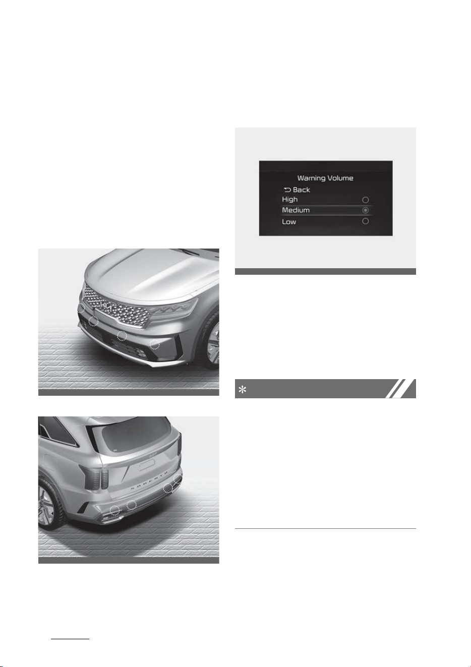
Features of your vehicle
1345
Forward/Reverse Parking Distance Warning
(PDW)
Forward/Reverse Parking Dis
-
tance Warning (PDW) (if
equipped)
Forward/Reverse Parking Distance
Warning will warn the driver if an
obstacle is detected when the vehi
-
cle is moving forward or backward
at low speeds.
Detecting sensor
Front ultrasonic sensors
Rear ultrasonic sensors
Refer to the picture above for the
detailed location of the detecting
sensor.
Forward/Reverse Parking Distance
Warning Settings
Warning Volume
Select 'Settings → Driver Assistance
→ Warning Volume' from cluster or
infotainment system to change the
Warning Volume to 'High', 'Medium',
'Low' or 'Off' for Reverse Parking
Distance Warning.
NOTICE
䳜
If you change the Warning Vol
-
ume, the warning volume of other
Driver Assistance systems may
change.
䳜
Even if 'Off' is selected, the Warn
-
ing Volume of Reverse Parking
Distance Warning will not turn off
but the volume will sound as
'Low'.
Parking Distance Warning Auto On
You can set the Parking Distance
Waring to be ON at low speeds. To
use Parking Distance Warning Auto
OMQ4H041007
OMQ4AH041566
OMQ4041606
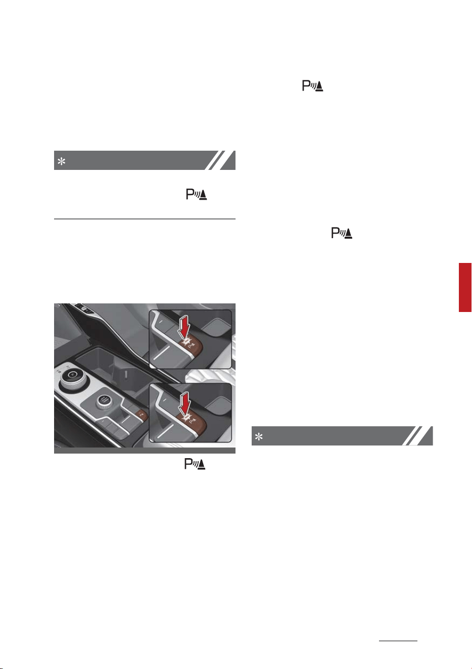
135
5
5
Features of your vehicle Forward/Reverse Parking Distance Warning
(PDW)
On function, select 'Settings →
Driver Assistance → Parking Safety
→ Parking Distance Warning Auto
On' from cluster or the infotainment
system with the Engine ON.
NOTICE
If Parking Distance Warning Auto On is
selected, the Parking Safety ( ) but
-
ton indicator light will turn on.
Forward/Reverse Parking Distance
Warning Operation
Parking Safety button (if equipped)
Press the Parking Safety ( ) but
-
ton to turn on or off Foward/
Reverse Parking Distance Warning.
䳜 When Reverse Parking Distance
Warning is off (button indicator
light off), if you shift the gear to R
(Reverse), Reverse Parking Dis
-
tance Warning will automatically
turn on.
䳜 If you shift the gear to R
(Reverse), Reverse Parking Dis
-
tance Warning will not turn off
even if you press the Parking
Safety ( ) button for your
safety.
Parking Safety button (if equipped)
Forward Parking Distance Warning
will operate when one of the condi
-
tion is satisfied.
䳜 The gear is shifted from R
(Reverse) to D (Drive)
The gear is in D (Drive) and the
Parking Safety ( ) button indica
-
tor light is on
䳜 'Parking Distance Warning Auto
On' is selected from the Settings
menu and the gear is in D (Drive)
䳜 The function warns the driver
when 'Settings → Driver Assis
-
tance → Parking Safety → Park
-
ing Distance Warning Auto On' is
selected from cluster or the info
-
tainment system, and the gear is
in D (Drive)
䳜 Vehicle speed is below 10 km/h (6
mph)
NOTICE
䳜
Forward Parking Distance Warn
-
ing does not operate when the
vehicle's forward speed is above
10 km/h (6 mph) even when the
function is on (Parking Safety
button indicator is on). Forward
Parking Distance Warning will
operate again when the vehicle's
forward speed decreases below
10 km/h (6 mph).
䳜
When the vehicle's forward speed
is above 30 km/h (18 mph), the
OMQ4PH040508L

Features of your vehicle
1365
Forward/Reverse Parking Distance Warning
(PDW)
Forward Parking Distance Warn
-
ing will turn off (Parking Safety
button indicator off). Although
you drive below 10 km/h (6 mph)
again, Forward Parking Distance
Warning will not automatically
turn on.
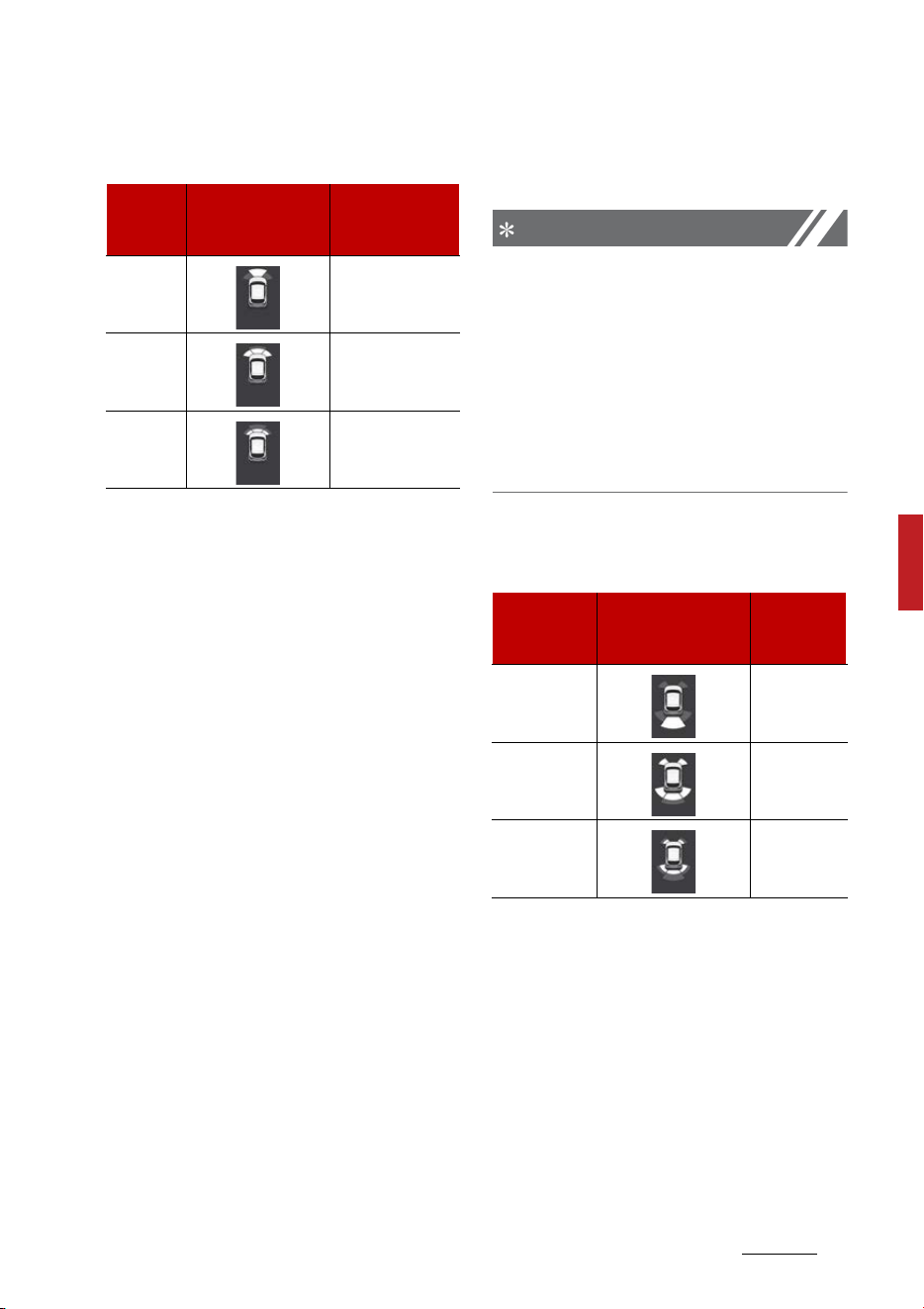
137
5
5
Features of your vehicle Forward/Reverse Parking Distance Warning
(PDW)
Function indications and warnings
䳜 The corresponding indicator will
illuminate on the cluster or info
-
tainment system screen when
-
ever each ultrasonic sensor
detects a person, animal or object
in its sensing range. Also an audi
-
ble warning will sound.
䳜 When more than two objects are
detected at the same time, the
closest one will be warned with an
audible warning.
䳜 Distance from object may be
detected differently when obsta
-
cles are not located in front of the
sensor.
䳜 The shape of the indicator in the
illustration may differ from the
actual vehicle.
Reverse Parking Distance Warning
Reverse Parking Distance Warning
will operate when one of the condi
-
tion is satisfied.
䳜 The gear is shifted to R (Reverse).
䳜 The vehicle's rearward speed is
below 10 km/h (6 mph).
NOTICE
When the vehicle's rearward speed
is below 10 km/h (6 mph), both the
front and rear ultrasonic sensors
will detect objects. However, the
front ultrasonic sensors can detect
a person, animal or object when it is
within 60 cm (24 in.) from the sen
-
sors.
Function indications and warnings
䳜 The corresponding indicator will
illuminate on the cluster or info
-
tainment system screen when
-
ever each ultrasonic sensor
detects a person, animal or object
in its sensing range. Also an audi
-
ble warning will sound.
䳜 When more than two objects are
detected at the same time, the
closest one will be warned with an
audible warning.
Distance
from
object
Warning indicator
when driving for
-
ward
Warning sound
24~40 in.
(60~100
cm)
Buzzer beeps
intermittently
12~24 in.
(30 ~60
cm)
Beeps more fre
-
quently
within 12
in. (30
cm)
Beeps continu
-
ously
Distance
from object
Warning indicator
when driving back
-
ward
Warning
sound
24~48 in.
(60~120 cm)
Buzzer
beeps inter
-
mittently
12~24 in. (30
~60 cm)
Beeps more
frequently
within 12 in.
(30 cm)
Beeps con
-
tinuously

Features of your vehicle
1385
Forward/Reverse Parking Distance Warning
(PDW)
䳜 Distance from object may be
detected differently when obsta
-
cles are not located in front of the
sensor.
䳜 The shape of the indicator in the
illustration may differ from the
actual vehicle.
Forward/Reverse Parking Distance
Warning Malfunction and Precau
-
tions
Forward/Reverse Parking Distance
Warning malfunction
After starting the vehicle, a beep
will sound once when the gear is
shifted to R (Reverse) to indicate
Forward/Reverse Parking Distance
Warning is operating normally.
However, if one or more of the fol
-
lowing occurs, first check whether
the ultrasonic sensor is damaged or
blocked with foreign material. If it
still does not work properly, Kia rec
-
ommends to visit an authorized Kia
dealer/service partner.
䳜 The audible warning does not
sound.
䳜 The buzzer sounds intermittently.
䳜 The warning message appears on
the cluster.
Limitations of
Forward/
Reverse
Parking Distance Warning
䳜 Forward/Reverse Parking Dis
-
tance Warning may not operate
normally when:
- Moisture is frozen to the sensor
(Reverse Parking Distance
Warning will operate normally
when it is melted.)
- Sensor is covered with foreign
material, such as snow or water
(Reverse Parking Distance
Warning will operate normally
when such foreign material are
removed.)
- The weather is extremely hot
or cold
- The sensor or sensor assembly
is disassembled
- The surface of the sensor is
pressed hard or an impact is
applied with a hard object
- The surface of the sensor is
scratched with a sharp object
OMQ4AH040557

139
5
5
Features of your vehicle Forward/Reverse Parking Distance Warning
(PDW)
- The sensors or its surrounding
area is directly sprayed with
high pressure washer
䳜 Forward/Reverse Parking Dis
-
tance Warning may malfunction
when:
- Heavy rain or water spray is
present
- Water flows on the surface of
the sensor
- Affected by another vehicle's
sensors
- The sensor is covered with
snow
- Driving on uneven road, gravel
roads or bushes
- Objects that generates ultra
-
sonic waves are near the sensor
- Installing the license plate dif
-
ferently from the original loca
-
tion
- The vehicle bumper height or
ultrasonic sensor installation
has been modified
- Attaching equipments or acces
-
sories around the ultrasonic
sensors
䳜 The following objects may not be
detected:
- Sharp or slim objects, such as
ropes, chains or small poles.
- Objects, which tend to absorb
sensor frequency, such as
clothes, spongy material or
snow.
- Objects smaller than 100 cm
(40 in.) in length and narrower
than 14 cm (6 in.) in diameter.
- Pedestrians, animals or objects
that are very close to the ultra
-
sonic sensors
WARNING
䳜 Forward/Reverse Parking Dis
-
tance Warning is a supplemental
function. The operation of For
-
ward/Reverse Parking Distance
Warning can be affected by sev
-
eral factors (including environ
-
mental conditions). It is the
responsibility of the driver to
always check the rear view before
and while parking.
䳜 Your vehicle warranty does not
cover any accidents or damage to
the vehicle due to the malfunction
of Reverse Parking Distance
Warning.
䳜 Pay close attention when driving
near objects, pedestrians, and
especially children. Some objects
may not be detected by the ultra
-
sonic sens s, due to the objects
distance, size material, all of
which can limit the effectiveness
of the sens .
䳜 Parking Distance Warning indica
-
tor may not occur sequentially
depending on vehicle speed or
obstacle shape.
䳜 If Forward/Reverse Parking Dis
-
tance Warning needs repair, Kia
recommends to visit an autho
-
rized Kia dealer/service partner

Features of your vehicle
1405
Lighting
Lighting
This vehicle is equipped with a vari
-
ety of lights to illuminate the inte
-
rior and exterior of the vehicle.
CAUTION
To prevent the battery from being
discharged, do not leave the head
-
lamp and interior light on for a pro
-
longed time while the engine is not
running.
Battery saver function
The purpose of this feature is to
prevent the battery from being dis
-
charged if the lights are left in the
ON position. The system automati
-
cally shuts off the parking lights
after the engine is off and the
driver's door is opened.
However, the position lamps stay
ON even when the driver-side door
is opened if the light switch is oper
-
ated after the engine is turned off.
If necessary, to keep the lamps on
turn the position lamps OFF and ON
again using the headlamp switch on
the steering column after the
engine is turned off.
Headlamp delay function
If you place the ENGINE START/
STOP button in the ACC or OFF posi
-
tion with the headlamps ON, the
headlamps (and/or position lamps)
remain on for about 5 minutes.
However, with the engine off if the
driver's door is opened and closed,
the headlamps (and/or position
lamps) are turned off after 15 sec
-
onds.
The headlamps (and/or position
lamps) can be turned off by press
-
ing the lock button on the smart key
twice or turning the light switch to
the OFF or AUTO position. However,
if you turn the light switch to the
AUTO position when it is dark out
-
side, the headlamps will not be
turned off.
You can activate or deactivate the
Headlamp Delay function from the
User Settings Mode in the LCD dis
-
play. For more details, refer to "LCD
display modes" on page 5-91. If
your vehicle is equipped with addi
-
tional navigation, please refer to the
infotainment system manual sepa
-
rately supplied.
NOTICE
If the driver exits the vehicle
through another door besides the
driver door, the battery saver func
-
tion does not operate and the head
-
lamp delay function does not turn
OFF automatically.
This may cause the battery to dis
-
charge. To avoid battery discharge,
turn OFF the headlamps manually
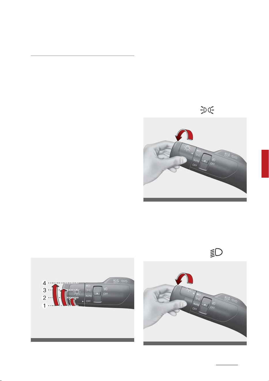
141
5
5
Features of your vehicle Lighting
from the headlamp switch before
exiting the vehicle.
Daytime Running Light (DRL) (if
equipped)
The Daytime Running Light (DRL)
can make it easier for others to see
the front of your vehicle during the
day.
The DRL can be helpful in many dif
-
ferent driving conditions, and it is
especially helpful after dawn and
before sunset.
The DRL will turn the dedicated
lamp OFF when:
䳜 The headlamps are on.
䳜 The vehicle is off.
䳜 The front fog light is on. (if
equipped)
䳜 Engaging the parking brake.
Lighting control
The light switch has a headlamp and
a position lamp position.
To operate the lights, turn the knob
at the end of the control lever to
one of the following positions:
1. OFF position
2. Auto light position
3. Position & Taillamp
4. Headlamp position
Position & Taillamp
When the light switch is in the posi
-
tion lamp position, the front position
lamp, taillamp, and the license plate
lamp will turn ON.
Headlamp (Low Beam)
OMQ4AH040051
OMQ4AH040055
OMQ4AH040053
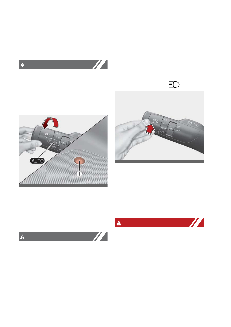
Features of your vehicle
1425
Lighting
When the light switch is in the head
-
lamp position, headlamp (low beam),
tail, license light will turn ON.
NOTICE
The ENGINE START/STOP button
must be in the ON position to turn
on the headlamps.
Auto light
When the light switch is in the AUTO
light position, the taillamps and
headlamps will turn ON or OFF auto
-
matically depending on the amount
of light outside the vehicle.
CAUTION
䳜 Never place anything over the
sensor (1) located on the instru
-
ment panel as this will ensure
better auto-light system control.
䳜 Don't clean the sensor using a
window cleaner, the cleaner may
leave a light film which could
interfere with sensor operation.
䳜 If your vehicle has window tint or
other types of metallic coating on
the front windshield, the Auto
light system may not work prop
-
erly.
Operating high beam
To turn on the high beam headlamp:
䳜 Push the lever away from you.
The lever will return to its original
position.
The high beam indicator will light
when the headlamp high beams
are switched on.
WARNING
High beams
Do not use high beam when there
are other vehicles in front of or
approaching your vehicle. Using high
beam could obstruct the other
driver's vision.
To flash the headlamps:
䳜 Pull the lever towards you.
OMQ4AH040052
OMQ4AH040056
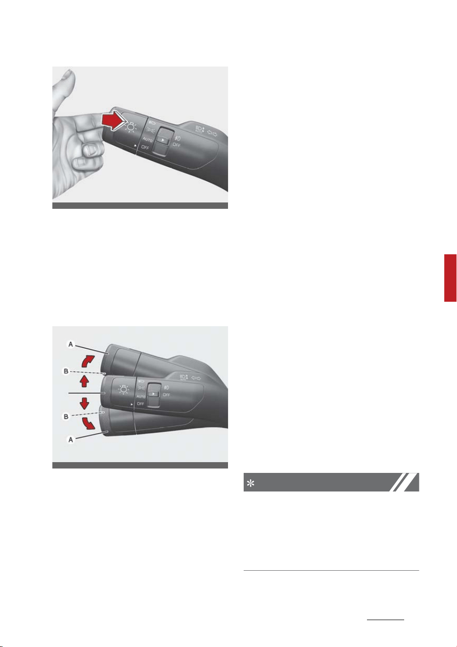
143
5
5
Features of your vehicle Lighting
It will return to the normal (low
beam) position when released.
The headlamp switch does not
need to be on to use this flashing
feature.
Operating turn signals and lane
change signals
The ENGINE START/STOP button
must be on for the turn signals to
function.
To turn on the turn signals:
䳜 Move the lever up or down (A).
The green arrow indicators on the
instrument panel indicate which
turn signal is operating.
They will self-cancel after a turn
is completed. If the indicator con
-
tinues to flash after a turn, man
-
ually return the lever to the OFF
position.
To signal a lane change:
䳜 Move the turn signal lever slightly
and hold it in position (B).
The lever will return to the OFF
position when released.
If an indicator stays on and does not
flash or if it flashes abnormally, one
of the turn signal bulbs may be
burned out and will require replace
-
ment.
One-touch lane change function
To activate a one-touch lane change
function, move the turn signal lever
slightly and then release it. The lane
change signals will blink 3, 5 or 7
times.
You can activate or deactivate the
One Touch Turn Signal function or
choose the number of blinking (3, 5,
or 7) by selecting "User Settings →
Lights → One Touch Turn signal".
NOTICE
If an indicator flash is abnormally
quick or slow, a bulb may be burned
out or have a poor electrical connec
-
tion in the circuit. The bulb may
require replacement.
OMQ4AH040054
OMQ4AH040057
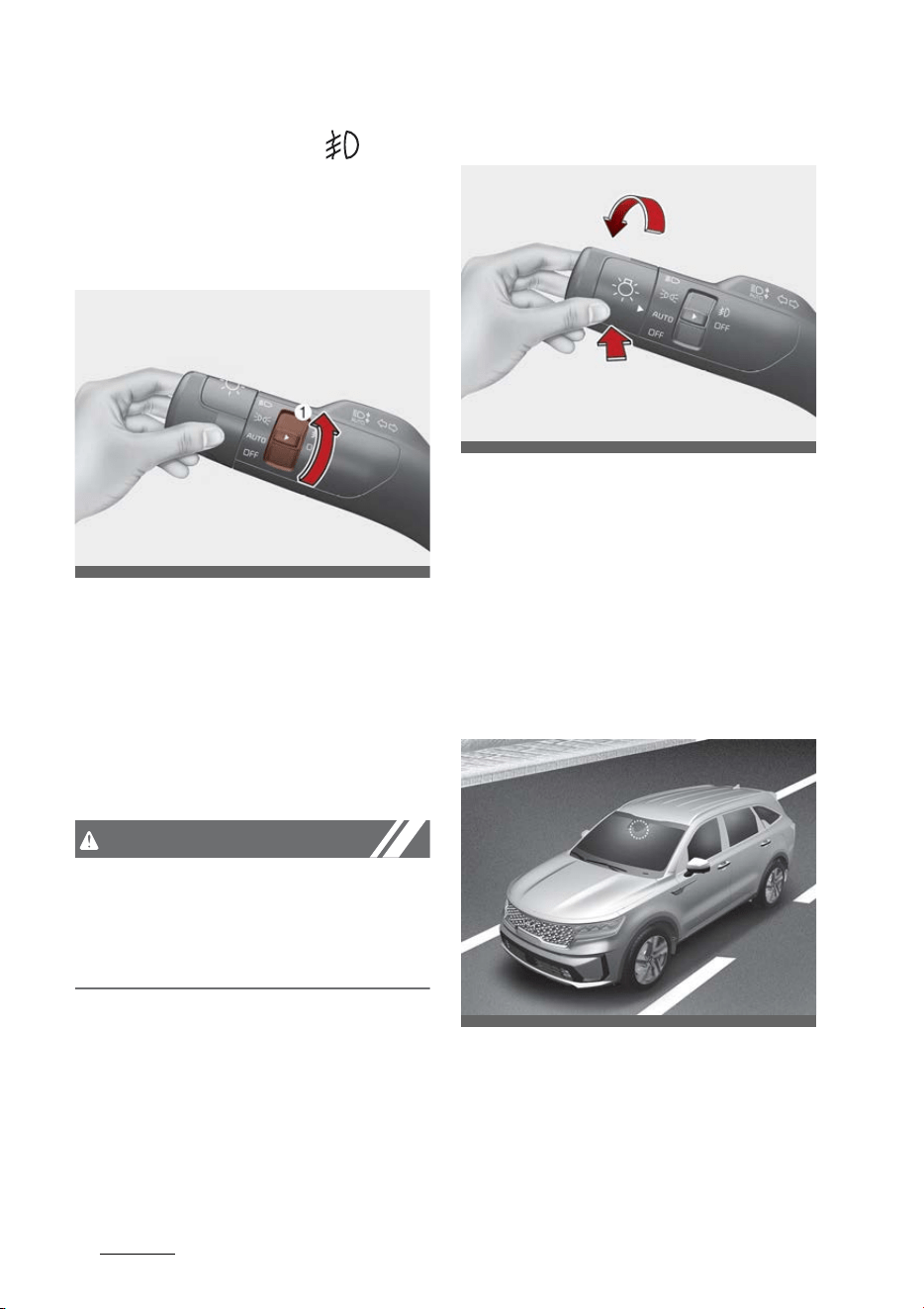
Features of your vehicle
1445
Lighting
Operating front fog light (if
equipped)
Fog lights are designed to provide
improved visibility when visibility is
poor due to fog, rain or snow, etc.
The fog lights will turn on when the
fog light switch (1) is turned to the
on position after the headlamp is
turned on.
To turn off the fog lights:
䳜 Turn the fog light switch (1) to
the ON position.
CAUTION
When in operation, the fog lights
consume large amounts of vehicle
electrical power. Only use the fog
lights when visibility is poor.
High Beam Assist (HBA)
High Beam Assist is a function that
automatically adjusts the headlamp
range (switches between high beam
and low beam) depending on the
brightness of detected vehicles and
certain road conditions.
Detecting sensor
Front view camera
The front view camera is used as a
detecting sensor to detect ambient
light and brightness while driving.
OMQ4AH040058
OMQ4AH040059
OMQ4H051009

145
5
5
Features of your vehicle Lighting
Refer to the picture above for the
detailed location of the detecting
sensor.
NOTICE
䳜 Always keep the front view cam
-
era in good condition to maintain
optimal performance of High
Beam Assist.
䳜 For more details on the precau
-
tions of the front view camera,
refer to"Forward Collision-Avoid
-
ance Assist (FCA) (Front view
camera only) (if equipped)" on
page 6-60.
High Beam Assist setting
With the ENGINE START/STOP
button in the ON position, select
'Lights → High Beam Assist' from
the Settings menu to turn on High
Beam Assist and deselect to turn
off the function.
WARNING
For your safety, adjust your high
beam settings only after parking
the vehicle at a safe location.
High Beam Assist operation
Display and control
䳜 After selecting 'High Beam Assist'
in the Settings menu, High Beam
Assist will operate by following
the procedure below.
- Place the headlamp switch in
the AUTO position and push the
headlamp lever towards the
instrument cluster. The High
Beam Assist ( ) indicator light
will illuminate on the cluster
and the function will be
enabled.
- When the function is enabled,
high beam will turn on when
vehicle speed is above 25 mph
(40 km/h). When vehicle speed
is below 15 mph (25 km/h), high
beam will not turn on.
- The High Beam ( ) indicator
light will illuminate on the clus
-
ter when high beam is on.
䳜 When High Beam Assist is operat
-
ing, if the headlamp lever or
switch is used, the function oper
-
ates as follow:
- If the headlamp lever is pulled
towards you when the high
beam is off, the high beam will
turn on without High Beam
Assist canceled. When your
hand is off the lever, it will
move to the middle and the
high beam will turn off.
- If the headlamp lever is pulled
towards you when the high
beam is on by High Beam
Assist, low beam will be on and
the function will turn off.

Features of your vehicle
1465
Lighting
- If the headlamp switch is placed
from AUTO to another position
(headlamp/position/off), High
Beam Assist will turn off and
the corresponding lamp will
turn on.
䳜 When High Beam Assist is operat
-
ing, high beam switches to low
beam if any of the following con
-
ditions occur:
- When the headlamp of an
oncoming vehicle is detected.
- When the taillamp of a vehicle
in front is detected.
- When the headlamp or taillamp
of a motorcycle or a bicycle is
detected.
- When the surrounding ambient
light is bright enough that high
beams are not required.
- When streetlights or other
lights are detected.
Malfunction and limitations
Malfunction
When High Beam Assist is not work
-
ing properly, the 'Check High Beam
Assist (HBA) system' warning mes
-
sage will appear and warning light
( ) will illuminate on the cluster.
Have the function be inspected by
an authorized Kia dealer.
Limitations
High Beam Assist may not work
properly in the following situations:
䳜 Light from a vehicle is not
detected because of lamp dam
-
age, or because it is hidden from
sight, etc.
䳜 Headlamp of a vehicle is covered
with dust, snow or water.
䳜 A vehicle's headlamps are off but
the fog lamps are on and etc.
䳜 There is a lamp that has a similar
shape as a vehicle's lamp.
䳜 Headlamps have been damaged or
not repaired properly.
䳜 Headlamps are not aimed prop
-
erly.
䳜 Driving on a narrow curved road,
rough road, uphill or downhill.
䳜 Vehicle in front is partially visible
on a crossroad or curved road.
䳜 There is a traffic light, reflecting
sign, flashing sign or mirror
ahead.
䳜 There is a temporary reflector or
flash ahead (construction area).
䳜 The road conditions are bad such
as being wet, iced or covered with
snow.
OMQ4HQ010031L
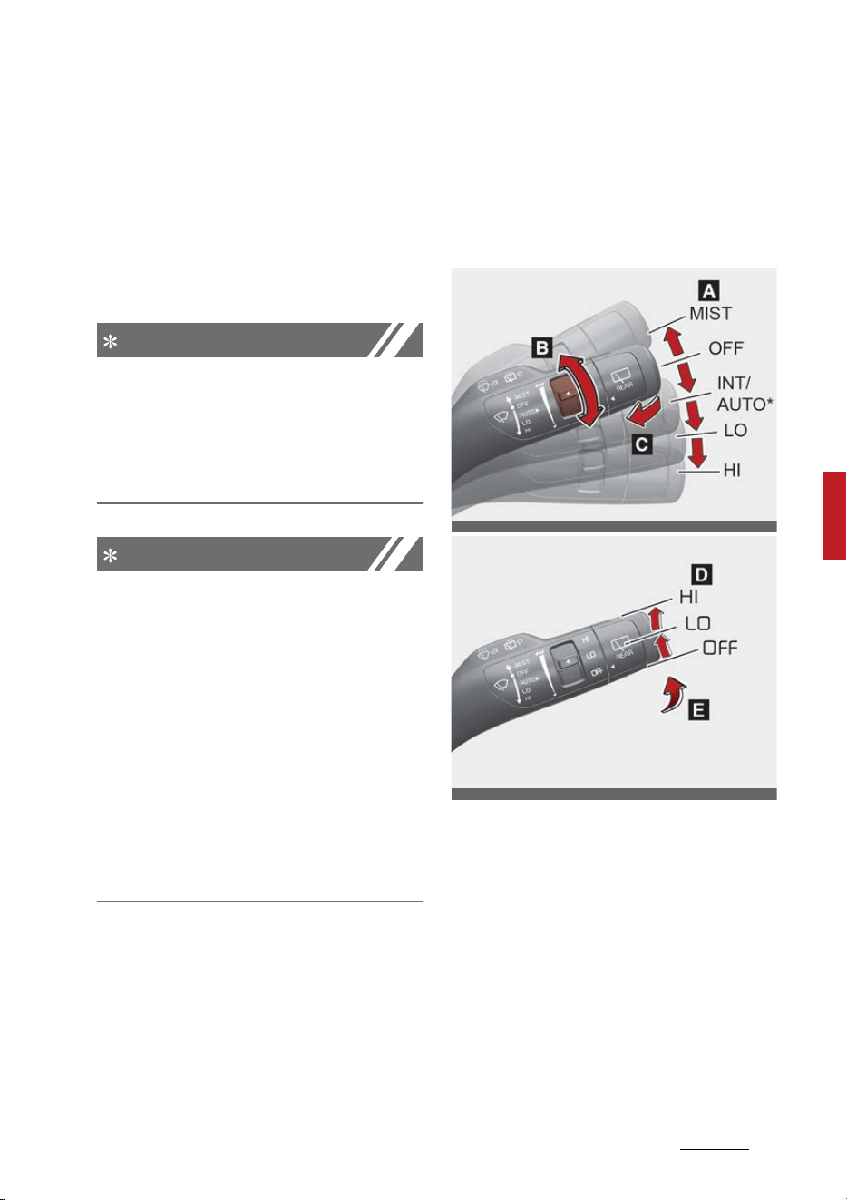
147
5
5
Features of your vehicle Wipers and washers
䳜 A vehicle suddenly appears from a
curve.
䳜 The vehicle is tilted from a flat
tire or is being towed.
䳜 Light from a vehicle is not
detected because of exhaust
fume, smoke, fog, snow, etc.
NOTICE
For more details on the limitations
of the front view camera, refer to
"Forward Collision-Avoidance Assist
(FCA) (Front view camera only) (if
equipped)" on page 6-60.
NOTICE
䳜 At times, High Beam Assist may
not work properly. The function is
for your convenience only. It is the
responsibility of the driver for
safe driving practices and always
check the road conditions for your
safety.
䳜 When High Beam Assist does not
operate normally, change the
headlamp position manually
between high beam and low
beam.
Wipers and washers
The wipers and washers remove
foreign substances from the wind
-
shield and rear window, helping to
maintain visibility.
A: Wiper speed control
䳜 MIST 䳍 Single wipe
䳜 OFF 䳍 Off
䳜 INT 䳍 Intermittent wipe
AUTO* 䳍 Auto control wipe
䳜 LO 䳍 Low wiper speed
䳜 HI 䳍 High wiper speed
B: Intermittent control wipe time
adjustment/Auto control wipe time
adjustment*
OMQ4040061
OMQ4040062
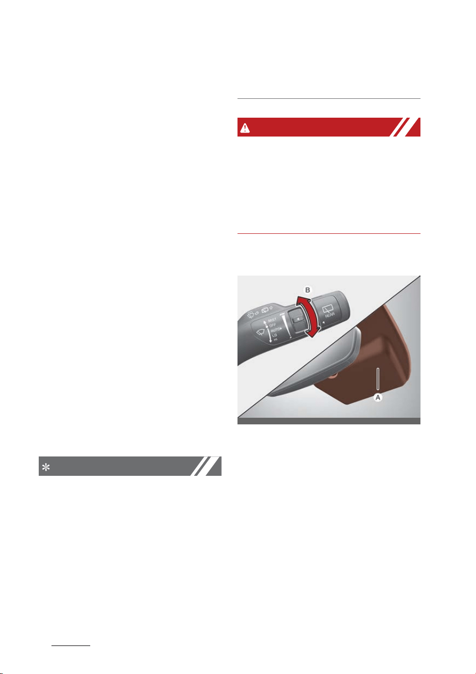
Features of your vehicle
1485
Wipers and washers
C: Wash with brief wipes
D: Rear wiper/washer control
䳜 HI - Continuous wipe
䳜 LO - Intermittent wipe
䳜 OFF - Off
E: Wash with brief wipes (rear)
*: if equipped
Windshield wipers
Operate as follows when the
ENGINE START/STOP button is ON.
䳜 MIST: For a single wiping cycle,
move the lever to this position
and release it. The wipers will
operate continuously if the lever
is held in this position.
䳜 OFF: Wiper is not in operation
䳜 INT: Wiper operates intermit
-
tently at the same wiping inter
-
vals. Use this mode in light rain or
mist. To vary the speed setting,
turn the speed control knob.
䳜 LO: Normal wiper speed
䳜 HI: Fast wiper speed
NOTICE
If there is heavy accumulation of
snow or ice on the windshield,
defrost the windshield for about 10
minutes, or until the snow and/or
ice is removed before using the
windshield wipers to ensure proper
operation. If you do not remove the
snow and/or ice before using the
wiper and wash-er, it may damage
the wiper and washer system.
WARNING
Do not use the washer in freezing
temperatures without first warming
the windshield with the defrosters;
the washer solution could freeze on
the windshield and obscure your
vision.
Auto control (if equipped)
The rain sensor (A) located on the
upper end of the windshield glass
senses the amount of rainfall and
controls the wiping cycle for the
proper interval. The more it rains,
the faster the wiper operates. When
the rain stops, the wiper stops.
To vary the speed setting, turn the
speed control knob (B).
If the wiper switch is set in AUTO
mode when the ENGINE START/
STOP button is ON, the wiper will
OMQ4040064
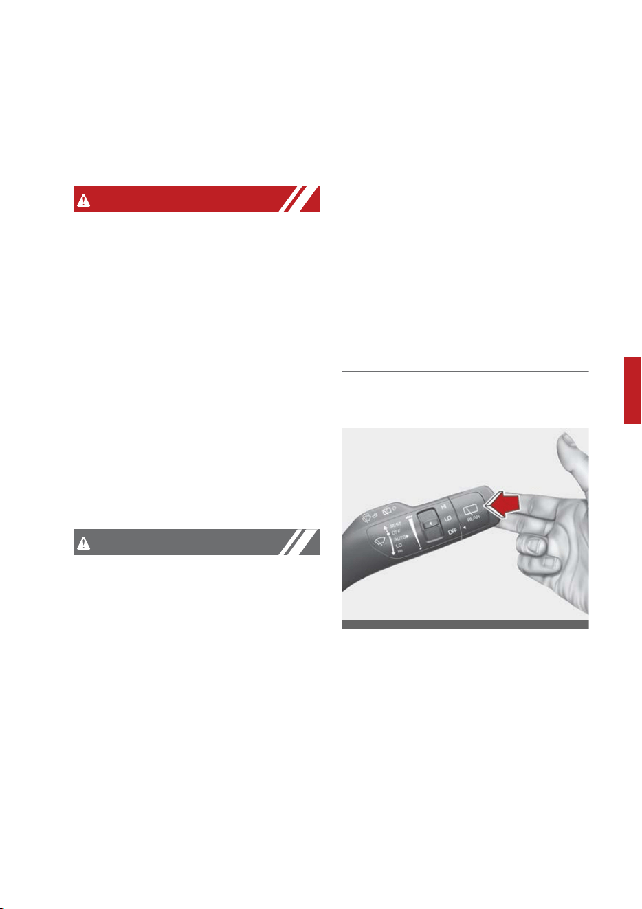
149
5
5
Features of your vehicle Wipers and washers
operate once to perform a self-
check of the system. Set the wiper
to OFF position when the wiper is
not in use.
WARNING
When the ENGINE START/STOP
button is ON and the windshield
wiper switch is placed in the AUTO
mode, use caution in the following
situations to avoid any injury to the
hands or other parts of the body:
䳜 Do not touch the upper end of the
windshield glass facing the rain
sensor.
䳜 Do not wipe the upper end of the
windshield glass with a damp or
wet cloth.
䳜 Do not put pressure on the wind
-
shield glass.
CAUTION
䳜 When washing the vehicle, set the
wiper switch in the OFF position
to stop the auto wiper operation.
The wiper may operate and be
damaged if the switch is set in the
AUTO mode while washing the
vehicle.
䳜 Do not remove the sensor cover
located on the upper end of the
passenger side windshield glass.
Damage to system parts could
occur and may not be covered by
your vehicle warranty.
䳜 When starting the vehicle in win
-
ter, set the wiper switch in the
OFF position. Otherwise, wipers
may operate and ice may damage
the windshield wiper blades.
Always remove all snow and ice
and defrost the windshield prop
-
erly prior to operating the wind
-
shield wipers.
䳜 When tinting the windshield, be
careful of any fluid getting into
the sensor located in the top cen
-
ter of the front windshield. It may
damage the related parts.
Operating windshield washers
1. Move the wiper speed control
switch to In OFF position.
2. Pull the lever gently toward you
to spray washer fluid on the
windshield and to run the wipers
1-3 cycles. Use this function
when the windshield is dirty. The
spray and wiper operation will
continue until you release the
lever.
OMQ4040066
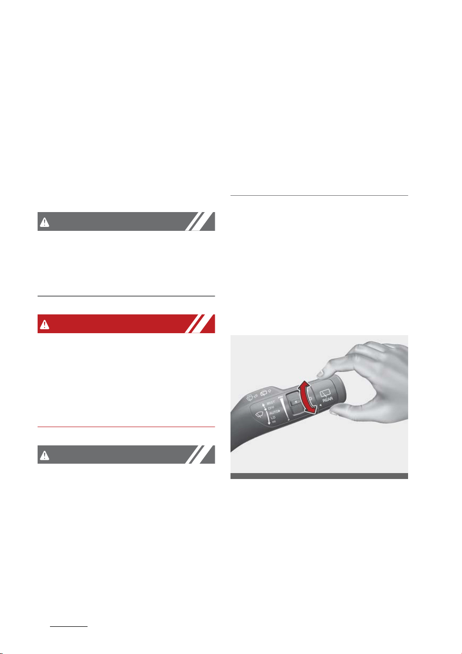
Features of your vehicle
1505
Wipers and washers
If the washer does not work, check
the washer fluid level. If the fluid
level is not sufficient, you will need
to add appropriate non-abrasive
windshield washer fluid to the
washer reservoir.
The reservoir filler neck is located in
the front of the engine compart
-
ment on the passenger side.
CAUTION
To prevent possible damage to the
washer pump, do not operate the
washer when the fluid reservoir is
empty.
WARNING
Do not use the washer in freezing
temperatures without first warming
the windshield with the defrosters;
the washer solution could freeze on
the windshield and obscure your
vision.
CAUTION
䳜 To prevent possible damage to
the wipers or windshield, do not
operate the wipers when the
windshield is dry.
䳜 To prevent damage to the wiper
blades, do not use gasoline, kero
-
sene, paint thinner, or other sol
-
vents on or near them.
䳜 To prevent damage to the wiper
arms and other components, do
not attempt to move the wipers
manually.
䳜 To prevent possible damage to
the wipers and washer system,
use anti-freezing washer fluids in
the winter season or cold
weather.
Operating rear window wiper and
washer switch
The rear window wiper and washer
switch is located at the end of the
wiper and washer switch lever.
䳜 Turn the switch to the desired
position to operate the rear wiper
and washer.
䳜 HI - Normal wiper operation
䳜 LO - Intermittent wiper opera
-
tion
䳜 OFF - Wiper is not in operation
䳜 Push the lever away from you to
spray rear washer fluid and to run
the rear wipers several times.
OMQ4AH040495
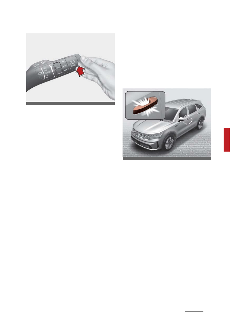
151
5
5
Features of your vehicle Welcome system
The spray and wiper operation will
continue until you release the lever.
When the front wiper is activated
and the gear is switched to R
(Reverse) position, the rear wiper
will be activated once to provide
better visibility.
Welcome system (if equipped)
The welcome system is a function
that illuminates the surroundings or
the interior when the driver
approaches or exits the vehicle.
Door handle lamp (if equipped)
When all the doors (and liftgate) are
closed and locked, the door handle
lamp will come on for about 15 sec
-
onds if any of the below is per
-
formed.
䳜 When the door unlock button is
pressed on the smart key.
䳜 When the button of the outside
door handle is pressed.
䳜 When the vehicle is approached
with the smart key in possession.
Headlamp escort function
The headlamps (and/or taillamps)
remain on for approximately 5 min
-
utes after the vehicle is turned off.
However, if the driver's door is
opened and closed, the headlamps
are turned off after 15 seconds.
OMQ4040067
OMQ4H041006

Features of your vehicle
1525
Interior lights
The headlamps can be turned off by
pressing the lock button on the
transmitter or smart key twice or
turning off the light switch from the
headlamp or Auto light position.
Interior light
When the interior light switch is in
the DOOR position and all doors (and
liftgate) are locked and closed, the
room lamp will come on for 30 sec
-
onds if any of the following occurs:
䳜 With the smart key system
- When the door unlock button is
pressed on the smart key.
- When the button of the outside
door handle is pressed.
At this time, if you press the door
lock button, the lamps will turn off
immediately.
Interior lights
This vehicle is equipped with lights
throughout the vehicle to illuminate
the interior.
CAUTION
Do not use the interior lights for
extended periods when the engine is
not running.
It may cause battery discharge.
WARNING
Do not use the interior lights when
driving in the dark. Accidents could
happen because the view may be
obscured by interior lights.
Automatic turn off function
The interior lights automatically
turn off approximately 20 minutes
after the ENGINE START/STOP
button is turned off, if the lights are
in the ON position.
If your vehicle is equipped with the
theft alarm system, the interior
lights automatically turn off
approximately 5 seconds after the
system is armed.
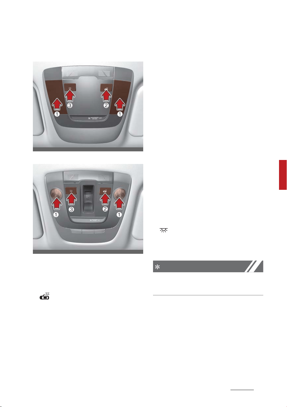
153
5
5
Features of your vehicle Interior lights
Map lamp
Type A
Type B
䳜 Press the lens (1) to turn ON the
map lamp.
To turn the map lamp OFF press
the lens (1) again.
䳜 (2): DOOR mode
- The map lamp and room lamp
come on when a door is opened.
The lamps go out after approx
-
imately 30 seconds.
- The map lamp and room lamp
come on for approximately 30
seconds when doors are
unlocked with a smart key as
long as the doors are not
opened.
- The map lamp and room lamp
will stay on for approximately
20 minutes if a door is opened
with the ENGINE START/STOP
button in the ACC or OFF posi
-
tion.
- The map lamp and room lamp
will stay on continuously if the
door is opened with the ENGINE
START/STOP button in the ON
position.
- The map lamp and room lamp
will go out immediately if the
ENGINE START/STOP button is
changed to the ON position or
all doors are locked.
- To turn off the DOOR mode,
press the DOOR button (2) once
again (not pressed).
䳜 (3): Press this switch to turn
the front and rear room lamps on
and off.
NOTICE
The DOOR mode and ROOM mode
can not be selected at a time.
OMQ4AH040087
OMQ4041567N
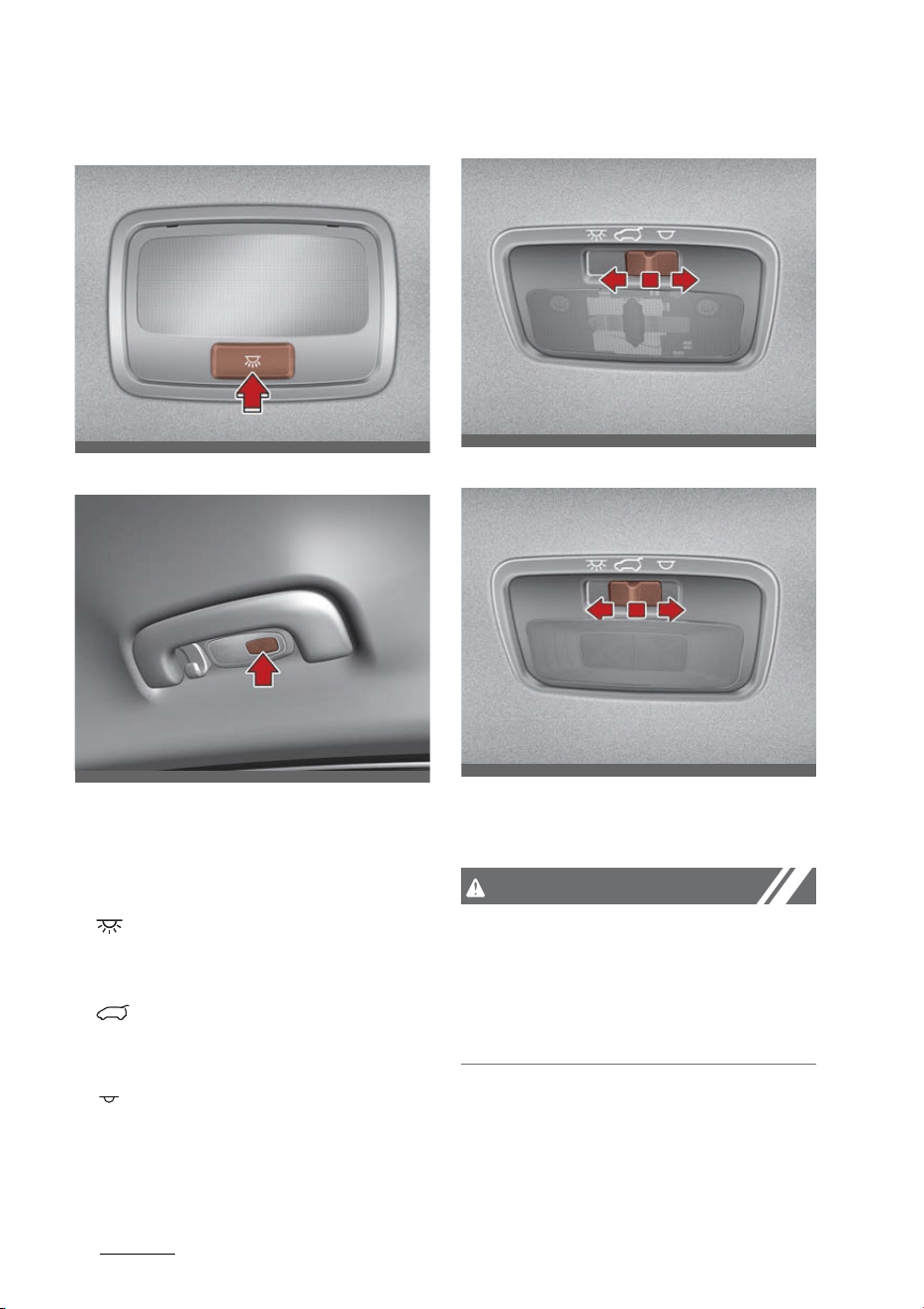
Features of your vehicle
1545
Interior lights
Room lamp (if equipped)
Personal lamp
Press the switch to turn the room
lamp on and off.
Luggage room lamp
䳜 : The lamp will always turn on
when the liftgate is opened/
closed.
䳜 : The lamp is on when the lift
-
gate is opened, and off when the
liftgate is closed.
䳜 : The lamp will always turn off
when the liftgate is opened/
closed.
Type A
Type B
The luggage room lamp comes on
when the liftgate is opened.
CAUTION
The luggage room lamp comes on as
long as the liftgate opens. To pre
-
vent unnecessary charging system
drain, close the liftgate securely
after using the luggage room.
OMQ4040411
OMQ4040412
OMQ4040410
OMQ4040409
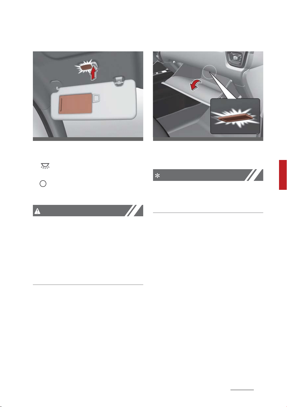
155
5
5
Features of your vehicle Interior lights
Vanity mirror lamp (if equipped)
Push the switch to turn the light on
or off.
䳜 : The lamp will turn on if this
button is pressed.
䳜 : The lamp will turn off if this
button is pressed.
CAUTION
Vanity mirror lamp
Always close the lid of the vanity
mirror in the off position when the
vanity mirror lamp is not in use. If
the sun visor is closed without the
lamp off, it may discharge the bat
-
tery or damage the sun visor.
Glove box lamp (if equipped)
The glove box lamp comes on when
the glove box is opened.
NOTICE
To prevent unnecessary charging
system drain, close the glove box
securely after using the glove box.
OMQ4040092
OMQ4040417

Features of your vehicle
1565
Climate control system
Climate control system
The climate control system uses
cooling and heating to help maintain
a pleasant environment inside the
vehicle.
System operation
Ventilation
1. Set the mode to the ( ) posi
-
tion.
2. Set the air intake control to the
outside (fresh) air position.
3. Set the temperature control to
the desired position.
4. Set the fan speed control to the
desired speed.
Heating
1. Set the mode to the ( ) posi
-
tion.
2. Set the air intake control to the
outside (fresh) air position.
3. Set the temperature control to
the desired position.
4. Set the fan speed control to the
desired speed.
5. If dehumidified heating is desired,
turn the air conditioning system
on.
䳜 If the windshield fogs up, set
the mode to the ( ) or ( )
position.
Operation tips
䳜 To keep dust or unpleasant fumes
from entering the vehicle through
the ventilation system, tempo
-
rarily set the air intake control to
the recirculated air position. Be
sure to return the control to the
fresh air position when the irrita
-
tion has passed to keep fresh air
in the vehicle. This will help keep
the driver alert and comfortable.
䳜 Air for the heating/cooling system
is drawn in through the grilles just
at the base of the windshield.
Care should be taken that these
are not blocked by leaves, snow,
ice or other obstructions.
䳜 To prevent fog from forming on
the inside of the windshield:
- Set the air intake control to the
fresh air position and the fan
speed to the desired position.
- Turn on the air conditioning
system, and adjust the tem
-
perature control to desired
temperature.
Air conditioning (A/C)
All Kia air conditioning systems are
filled with R-1234yf refrigerant.
1. Start the vehicle. Press the A/C
button.
2. Set the mode to the ( ) posi
-
tion.
3. Set the air intake control to the
outside-air or recirculated air
position.

157
5
5
Features of your vehicle Climate control system
4. Adjust the fan speed control and
temperature control to maintain
maximum comfort.
NOTICE
䳜 The refrigerant system should
only be serviced by trained and
certified technicians to insure
proper and safe operation.
䳜 The refrigerant system should be
serviced in a well-ventilated place.
䳜 The air conditioning evaporator
(cooling coil) shall never be
repaired or replaced with one
removed from a used or salvaged
vehicle and new replacement MAC
evaporators shall be certified (and
labeled) as meeting SAE Standard
J2842.
CAUTION
Excessive air conditioning use
When using the air conditioning sys
-
tem, monitor the temperature
gauge closely while driving up hills or
in heavy traffic when outside tem
-
peratures are high. Air conditioning
system operation may cause vehicle
overheating. Continue to use the
blower fan but turn the air condi
-
tioning system off if the tempera
-
ture gauge indicates vehicle
overheating.
CAUTION
The air conditioning system should
only be used with the windows and
sunroof closed to prevent conden
-
sation inside the vehicle that may
cause damage to electrical compo
-
nents.
Air conditioning system operation
tips
䳜 If the vehicle has been parked in
direct sunlight during hot
weather, open the windows for a
short time to let the hot air inside
the vehicle escape.
䳜 To help reduce moisture inside of
the windows on rainy or humid
days, decrease the humidity
inside the vehicle by operating the
air conditioning system.
䳜 During air conditioning system
operation, you may occasionally
notice a slight change in vehicle
speed as the air conditioning
compressor cycles. This is a nor
-
mal characteristic of system
operation.
䳜 To ensure maximum system per
-
formance, the air conditioning
system should be run for a few
minutes each month.
䳜 When using the air conditioning
system, you may notice clear
water dripping (or even puddling)
on the ground under the passen
-
ger side of the vehicle. This is a
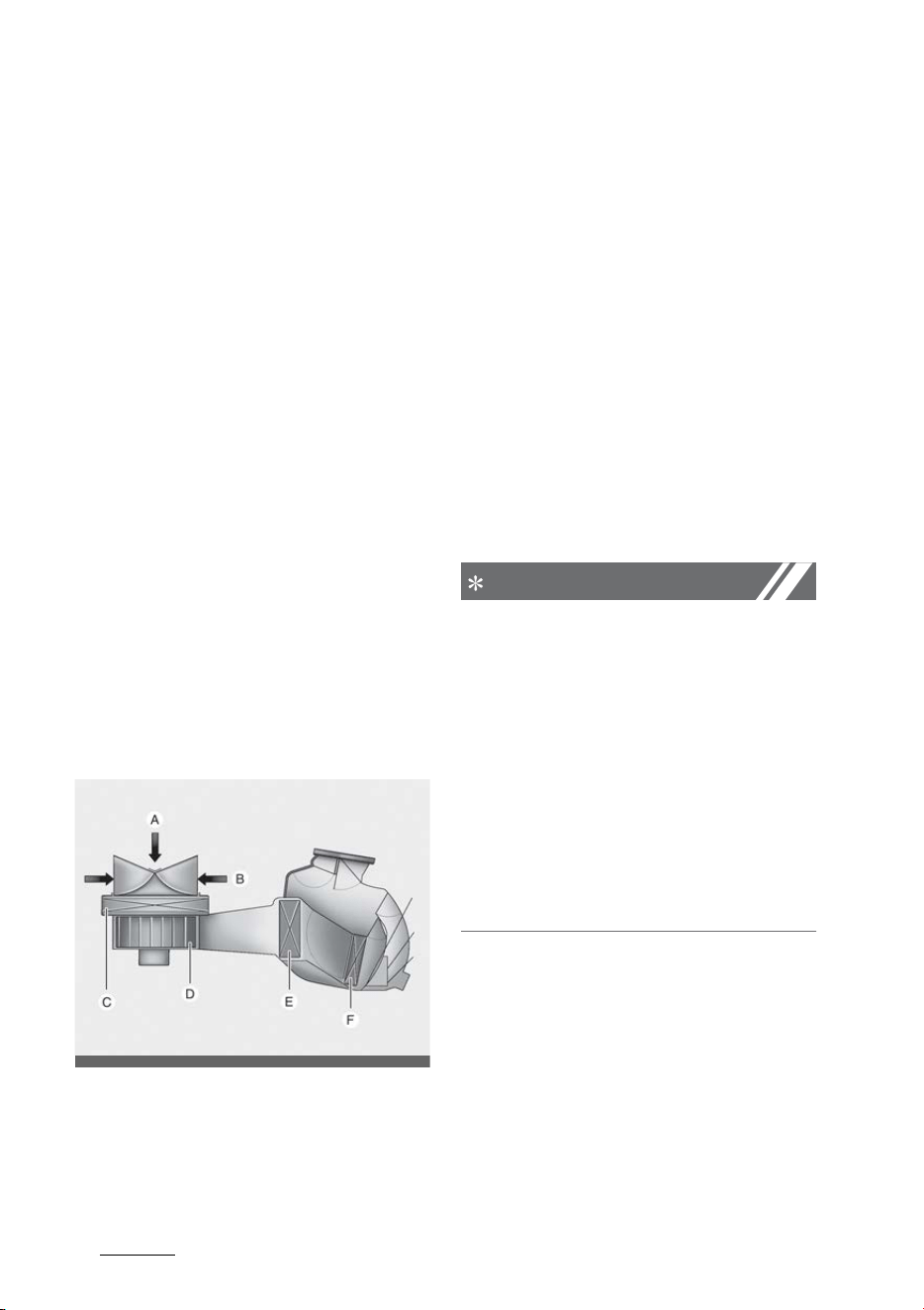
Features of your vehicle
1585
Climate control system
normal characteristic of system
operation.
䳜 Operating the air conditioning
system in the recirculated air
position provides maximum cool
-
ing; however, continual operation
in this mode may cause the air
inside the vehicle to become stale.
䳜 During cooling operation, you may
occasionally notice a misty air
flow because of rapid cooling and
humid air intake. This is a normal
characteristic of system opera
-
tion.
Climate control air filter
The climate control air filter
installed behind the glove box filters
the dust or other pollutants that
come into the vehicle from the out
-
side through the heating and air
conditioning system.
A: Outside air
B: Recirculated air
C: Climate control air filter
D: Blower
E: Evaporator core
F: Heater core
If dust or other pollutants accumu
-
late in the filter over a period of
time, the air flow from the air vents
may decrease. This leads to mois
-
ture accumulating on the inside of
the windshield even when the out
-
side (fresh) air position is selected. If
this happens, have the climate con
-
trol air filter replaced by an autho
-
rized Kia dealer.
NOTICE
䳜 Replace the filter according to the
Maintenance Schedule. If the
vehicle is being driven in severe
conditions such as dusty or rough
roads, more frequent air condi
-
tioner filter inspections and
changes are required.
䳜 When the air flow rate suddenly
decreases, have the system
checked by an authorized Kia
dealer.
ODEEV068230NR
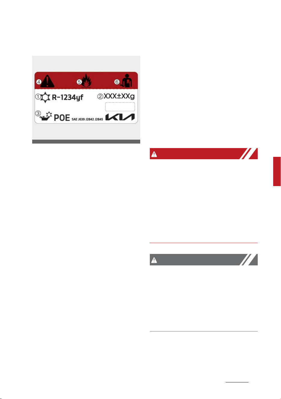
159
5
5
Features of your vehicle Climate control system
Air conditioning refrigerant label
* The actual air conditioning refrig
-
erant label in the vehicle may dif
-
fer from the illustration.
Each symbol and specification on
the air conditioning refrigerant label
is represented below:
1. Classification of refrigerant
2. Amount of refrigerant
3. Classification of Compressor lubri
-
cant
4. Caution
5. Flammable Refrigerant
6. Registered technician to service
Air Conditioning system
You can find out which air condition
-
ing refrigerant is applied your vehi
-
cle at the label inside of the engine
compartment.
Refer to "Refrigerant label" on page
9-13 for more detail on the location
of air conditioning refrigerant label.
Checking the amount of air condi
-
tioner refrigerant and compressor
lubricant
When the amount of refrigerant is
low, the performance of the air con
-
ditioning is reduced. Overfilling also
has a negative impact on the air
conditioning system.
Therefore, if abnormal operation is
found, have the system inspected
by an authorized Kia dealer.
WARNING
The oil and refrigerant in your vehi
-
cle's air conditioning system is
under very high pressure. If proper
service procedures are not followed,
an explosion may result. To reduce
the risk of serious injury or death,
the air conditioning system in your
vehicle should only be serviced by
trained and certified technicians.
CAUTION
It is important that the correct type
and amount of oil and refrigerant is
used, otherwise damage to the
vehicle may occur. To prevent dam
-
age, the air conditioning system in
your vehicle should only be serviced
by trained and certified technicians.
NN_OKA4040574N

Features of your vehicle
1605
Climate control system
WARNING
Vehicles equipped with R-1234yf*
Since the refrigerant is mildly flam
-
mable and operated at high pres
-
sure, the air conditioning system
should only be serviced by trained
and certified technicians.
It is important that the correct type
and amount of oil and refrigerant
are used. All refrigerants should be
reclaimed with proper equipment.
Venting refrigerants directly to the
atmosphere is harmful to individuals
and environment. Failure to heed
these warnings can lead to serious
injuries.
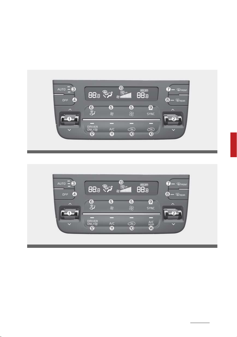
161
5
5
Features of your vehicle Automatic climate control system
Automatic climate control system
The automatic climate control system uses cooling and heating to help
maintain a pleasant environment inside the vehicle.
Type A
Type B
OMQ4H040301L
OMQ4H040300L
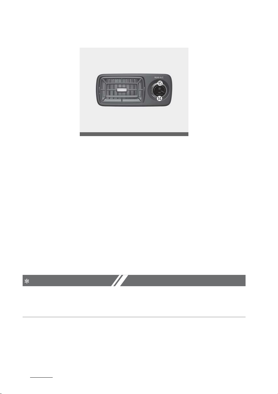
Features of your vehicle
1625
Automatic climate control system
3rd row seat
1. Driver's temperature control button
2. Passenger's temperature control button
3. AUTO (automatic control) button
4. OFF button
5. Fan speed control button
6. Mode selection button
7. Front windshield defroster button
8. Rear window defroster button
9. SYNC button
10.Air intake control button
11.Air conditioning (A/C) button
12.Driver's side only HVAC button
13.Climate control display
14.3rd row air conditioning ON/OFF button (if equipped)
15.3rd row air conditioning fan speed control knob (if equipped)
NOTICE
Operating the blower when the ENGINE START/STOP button is in the ON
position could cause the battery to discharge. Operate the blower when the
engine is running.
OMQ4H040303L
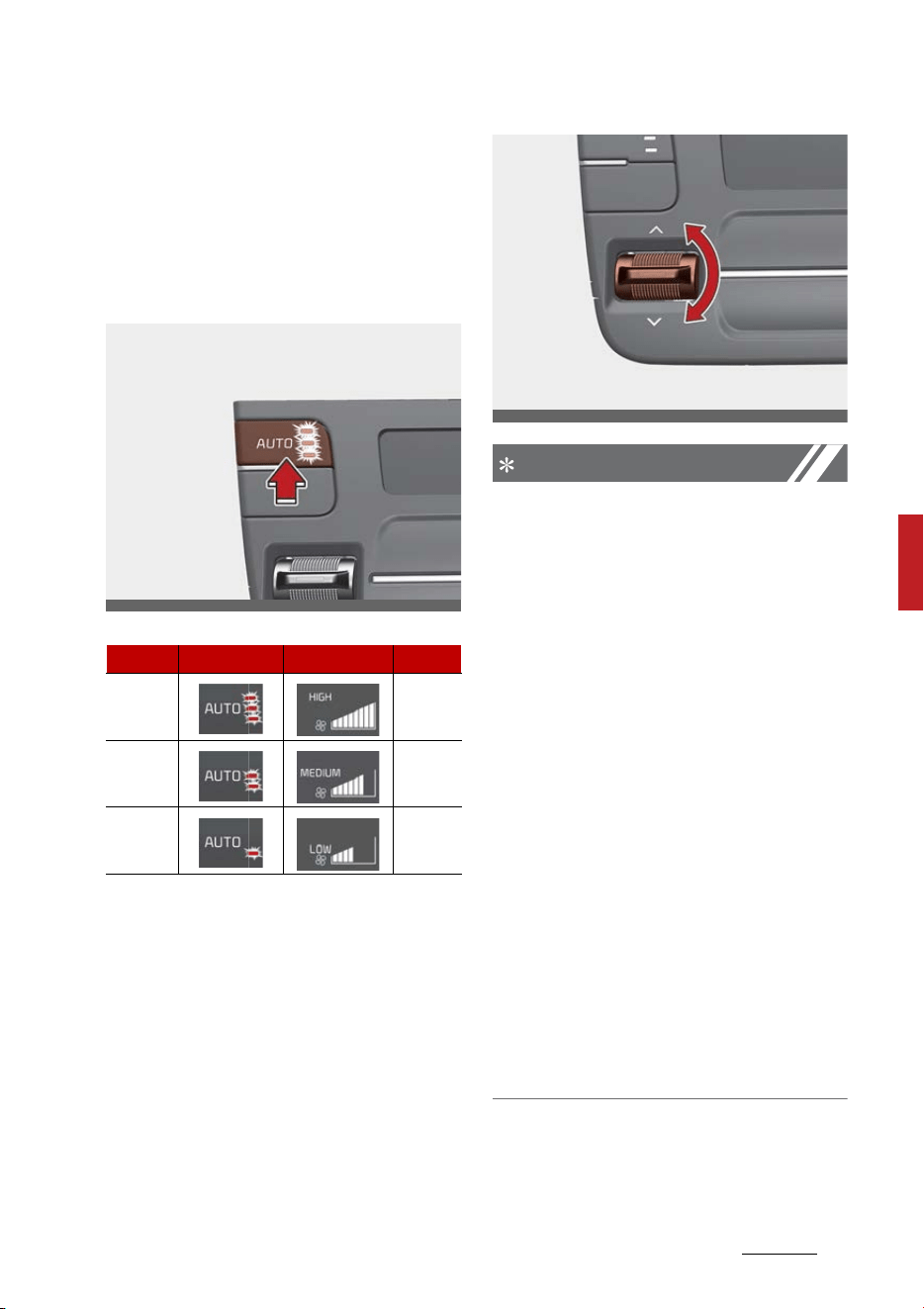
163
5
5
Features of your vehicle Automatic climate control system
Heating and air conditioning auto
-
matically
1. Press the AUTO button.
The modes, fan speeds, air intake
and air-conditioning will be con
-
trolled automatically by setting
the temperature.
2. Press the temperature control
button to the desired tempera
-
ture.
NOTICE
䳜 To turn the automatic operation
off, select any button or switch of
the following:
- Mode selection button
- Air conditioning button
- Front windshield defroster but
-
ton (Press the button one more
time to deselect the front
windshield defroster function.
The AUTO sign will illuminate on
the information display once
again.)
- Fan speed control knob
The selected function will be con
-
trolled manually while other func
-
tions operate automatically.
䳜 For your convenience and to
improve the effectiveness of the
climate control, use the AUTO
button and set the temperature
to 72 F (22 C).
Level Indicator LCD Display Air flow
High 1~8
Medium 1~7
Low 1~5
OMQ4040350L
OMQ4040351L
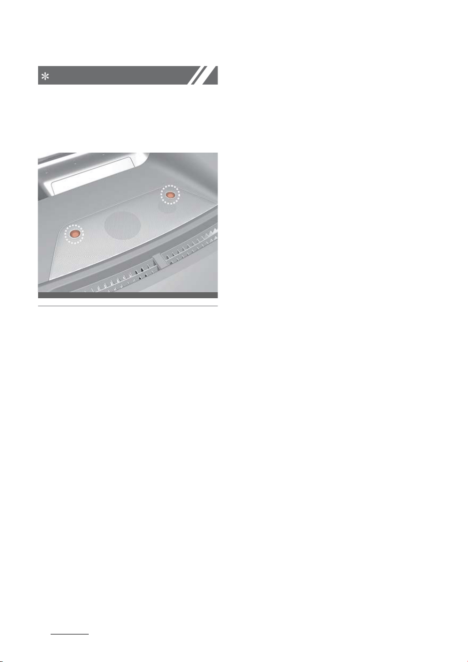
Features of your vehicle
1645
Automatic climate control system
NOTICE
Never place anything over the sen
-
sor located on the instrument panel
to ensure better control of the
heating and cooling system.
OMQ4040068
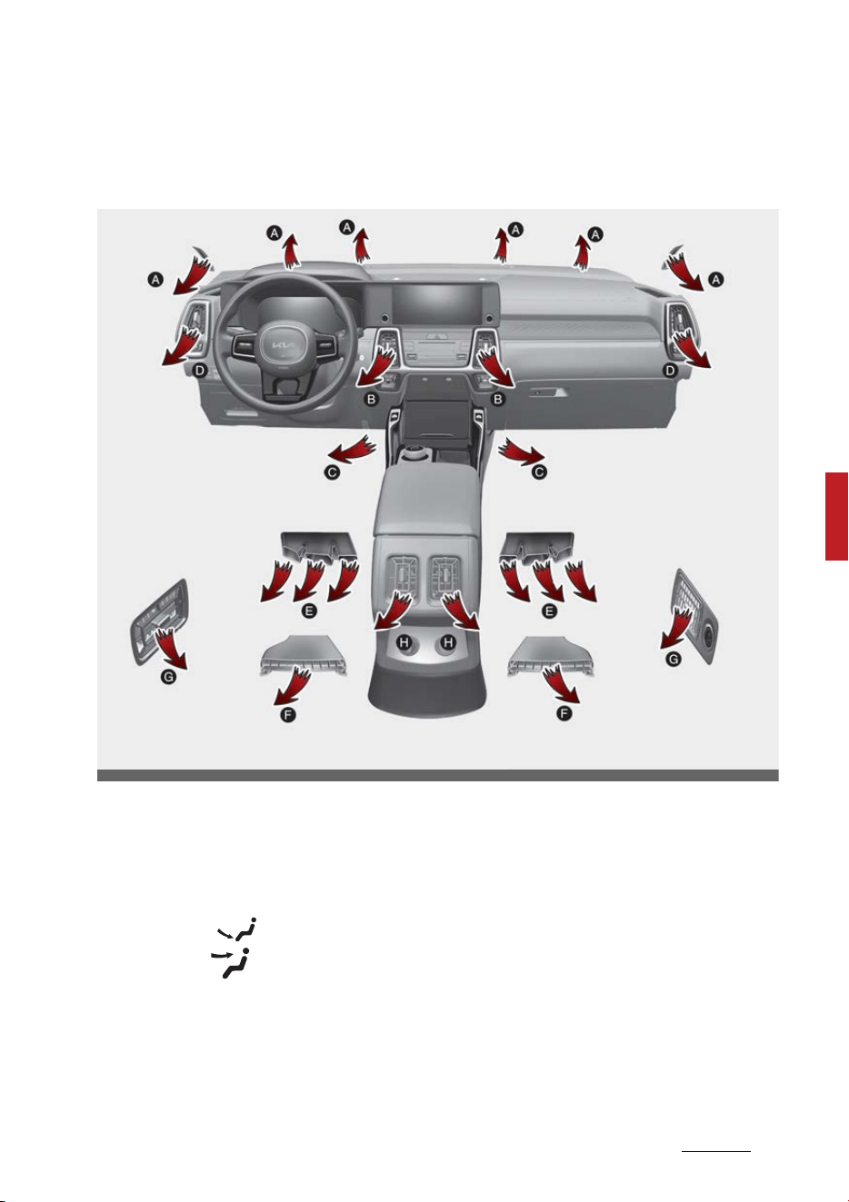
165
5
5
Features of your vehicle Automatic climate control system
Heating and air conditioning manually
The heating and cooling system can be controlled manually by pressing but
-
tons other than the AUTO button.
In this case, the system works sequentially according to the order of but
-
tons selected.
1. Start the vehicle.
2. Set the mode to the desired position.
For improving the effectiveness of heating and cooling;
䳜 Heating:
䳜 Cooling:
3. Set the temperature control to the desired position.
4. Set the air intake control to the outside (fresh) air position.
5. Set the fan speed control to the desired speed.
If air conditioning is desired, turn the air conditioning system on.
OMQ4041339L
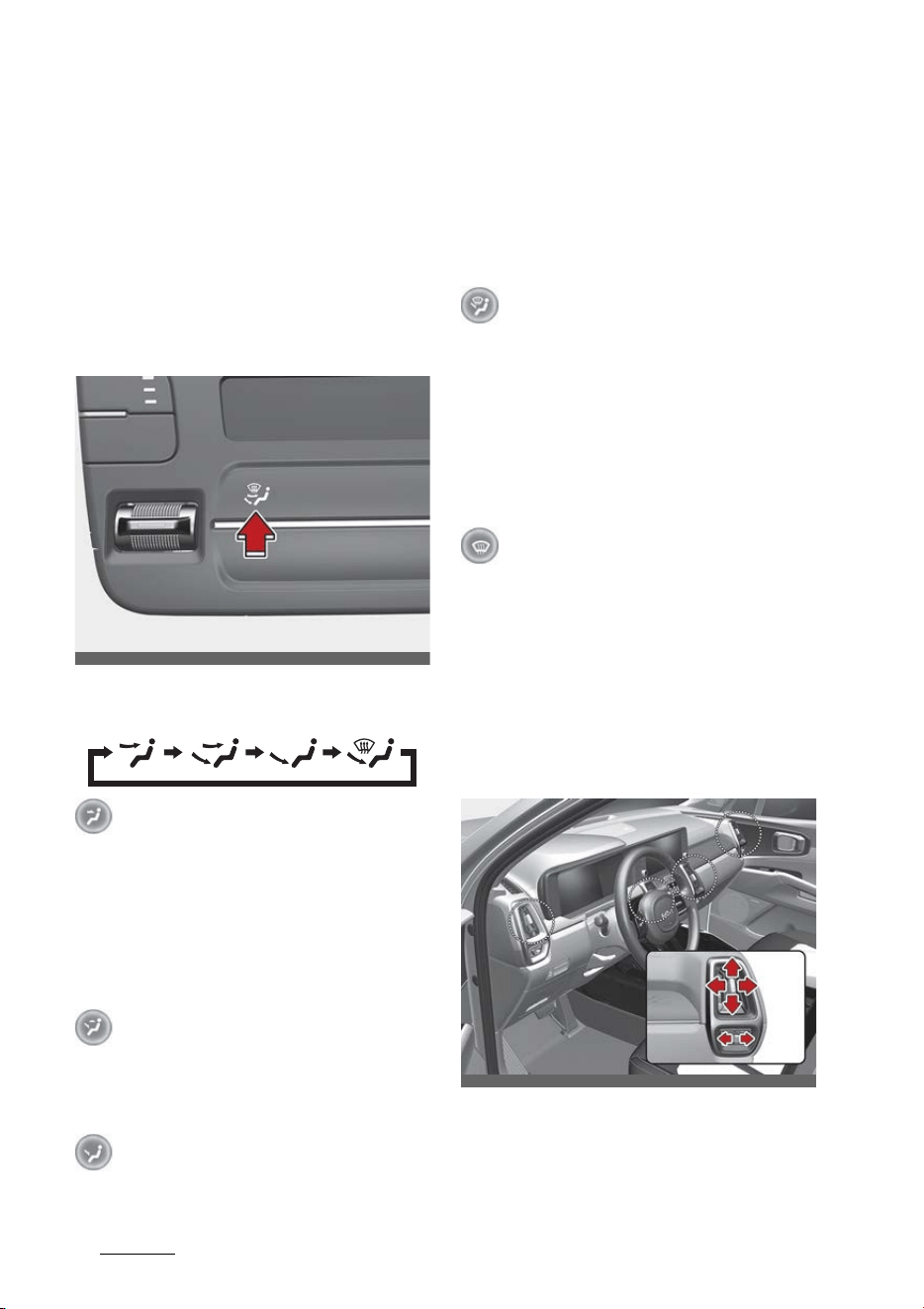
Features of your vehicle
1665
Automatic climate control system
Press the AUTO button in order to
convert to fully automatic control of
the system.
Mode selection
The mode selection button controls
the direction of the air flow through
the ventilation system.
The air flow outlet ports are
switched in the following sequence:
Face-Level (B, D, H)
Air flow is directed toward the
upper body and face. Additionally,
each outlet can be controlled to
direct the air discharged from the
outlet.
Bi-Level (B, C, D, E, F, H)
Air flow is directed towards the face
and the floor.
Floor-Level (A, C, D, E, F, H)
Most of the air flow is directed to
the floor, with a small amount of
the air being directed to the wind
-
shield, side window defrosters and
side air vents.
Floor/Defrost-Level (A, C, D, E,
F, H)
Most of the air flow is directed to
the floor and the windshield with a
small amount directed to the side
window defrosters and side air
vents.
Defrost-Level (A, D)
Most of the air flow is directed to
the windshield with a small amount
of air directed to the side window
defrosters and side air vents.
Instrument panel vents
Front
OMQ4040319L
OMQ4041336L
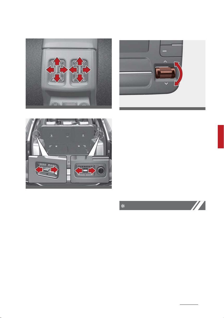
167
5
5
Features of your vehicle Automatic climate control system
Center
Rear
You can adjust the direction of air
delivered from these vents using the
vent control lever as shown.
Temperature control
The temperature will increase to the
maximum (HI) by moving the switch
upwards.
The temperature will decrease to
the minimum (Lo) by moving the
switch downwards.
When moving the switch, the tem
-
perature will increase or decrease
by 0.5 F. When set to the lowest
temperature setting, the air condi
-
tioning will operate continuously.
NOTICE
When starting the vehicle in cold
weather using manual temperature
control, operate the system in the
following method to improve heat
-
ing.
䳜 Turn off or lower the blower, right
after starting the engine.
䳜 Allow the engine to warm up
during this time since the air flow
from the heater is still cold.
OMQ4040335
OMQ4040337
OMQ4040321
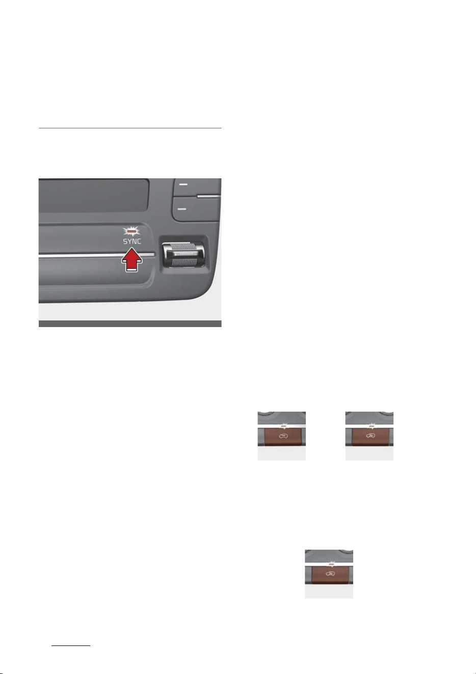
Features of your vehicle
1685
Automatic climate control system
䳜 After a few minutes of engine
warm up, turn on or set the fan to
a higher level and adjust the tem
-
perature setting to hot.
Adjusting the driver and passenger
side temperature equally
1. Press the "SYNC" button to adjust
the driver and passenger side
temperature equally.
The passenger side temperature
will be set to the same tempera
-
ture as the driver side tempera
-
ture.
2. Move the driver side temperature
control switch. The driver and
passenger side temperature will
be adjusted equally.
3. If you move the passenger's tem
-
perature control switch, the SYNC
button is off and the passenger
side temperature can be operated
individually.
Adjusting the driver and passenger
side temperature individually
Press the "SYNC" button again to
adjust the driver and passenger side
temperature individually. The but
-
ton indicator will turn off.
Changing temperature scale
You can switch the temperature
mode from Centigrade to Fahren
-
heit as follows:
䳜 While pressing the OFF button,
press the AUTO button for 3 sec
-
onds or more.
The display will change from Centi
-
grade to Fahrenheit, or from Fahr
-
enheit to Centigrade. If the battery
has been discharged or discon
-
nected, the temperature mode dis
-
play will reset to Centigrade.
Controlling air intake
This is used to select the outside
(fresh) air position or recirculated air
position.
To change the air intake control
position:
䳜 Push the desired control button.
Recirculated air position
With the recirculated air position
selected, air from the passenger
compartment will be drawn through
OMQ4040322
Type A Type B
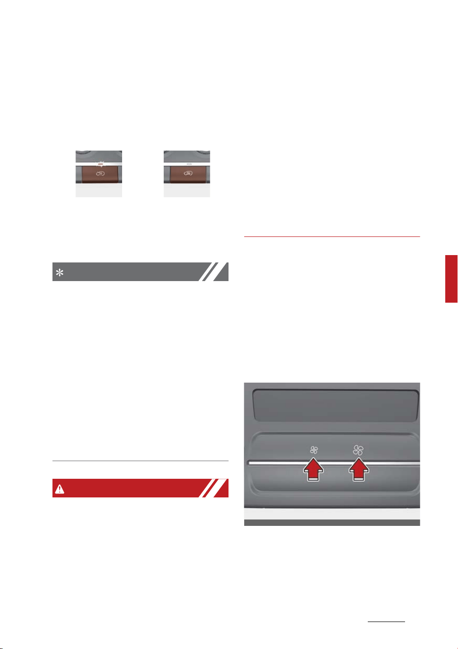
169
5
5
Features of your vehicle Automatic climate control system
the heating system and heated or
cooled according to the function
selected.
Outside (fresh) air position
With the outside (fresh) air position
selected, air enters the vehicle from
outside and is heated or cooled
according to the function selected.
NOTICE
Prolonged operation of the heater in
the recirculated air position (without
air conditioning selected) may cause
fogging of the windshield and side
windows and the air within the pas
-
senger compartment may become
stale.
In addition, prolonged use of the air
conditioning with the recirculated air
position selected will result in
excessively dry air in the passenger
compartment.
WARNING
䳜 Continued climate control system
operation in the recirculated air
position may allow humidity to
increase inside the vehicle which
may fog the glass and obscure
visibility.
䳜 Do not sleep in a vehicle with the
air conditioning or heating system
on. It may cause serious harm or
death due to a drop in the oxygen
level and/or body temperature.
䳜 Continued climate control system
operation in the recirculated air
position can cause drowsiness or
sleepiness, and loss of vehicle
control. Set the air intake control
to the outside (fresh) air position
as much as possible while driving.
Controlling fan speed
The fan speed can be set to the
desired speed by operating the fan
speed control button.
To change the fan speed:
䳜 Press right button for higher
speed, or press left button for
lower speed.
To turn the fan speed control off:
䳜 Press the OFF button.
Type A Type B
OMQ4040327
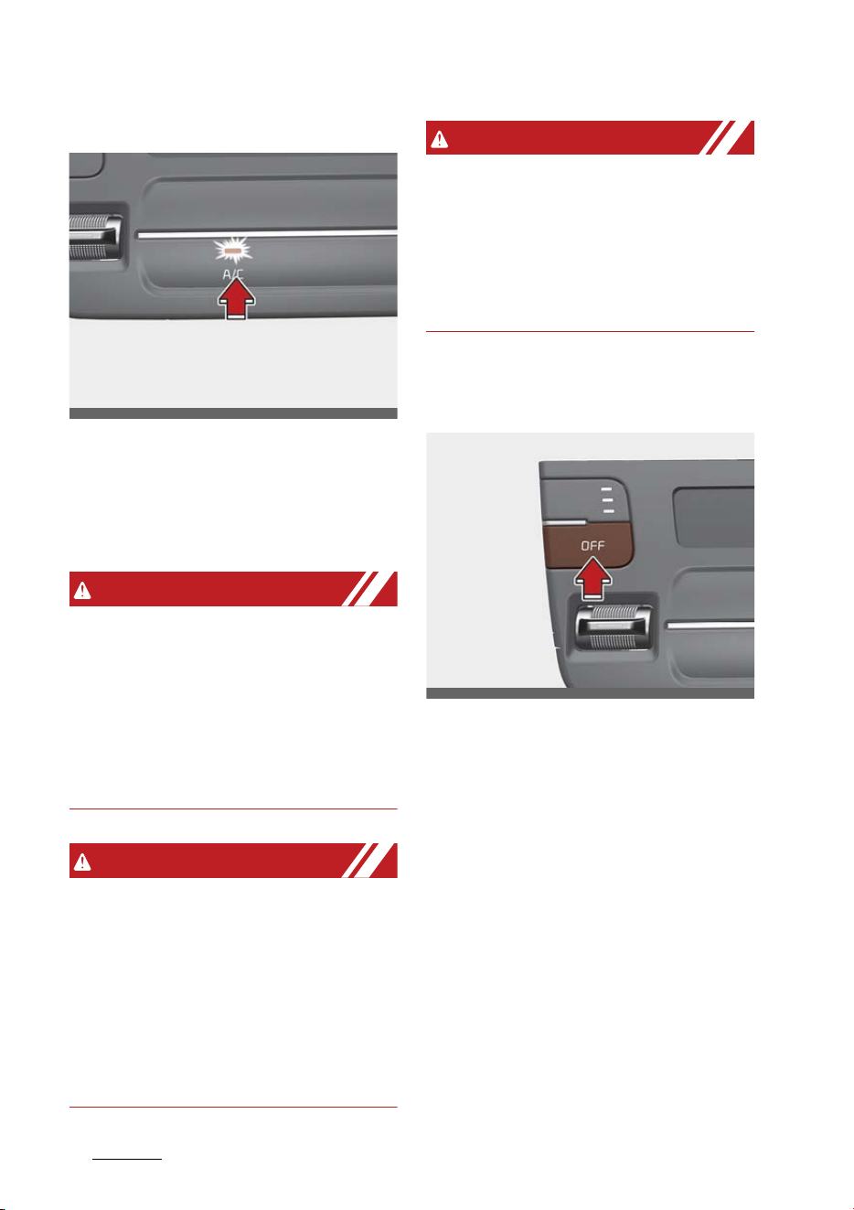
Features of your vehicle
1705
Automatic climate control system
Air conditioning (A/C)
䳜 Press the A/C button to turn the
air conditioning system on (indi
-
cator light will illuminate).
䳜 Press the button again to turn the
air conditioning system off.
WARNING
Reduced visibility
Continuous use of the climate con
-
trol system in the recirculated air
position may allow humidity to
increase inside the vehicle, which
may fog the glass and obscure visi
-
bility.
WARNING
Recirculated air
Continued use of the climate control
system in the recirculated air posi
-
tion can cause drowsiness or sleepi
-
ness, and loss of vehicle control. Set
the air intake control to the outside
(fresh) air position as much as pos
-
sible while driving.
WARNING
Sleeping with A/C on
Do not sleep in a vehicle with the air
conditioning or heating on as this
may cause serious harm or death
due to a drop in the oxygen level
and/or body temperature.
Turning off the front air climate
control
䳜 Press the OFF button to turn off
the air climate control system.
However, you can still operate the
mode and air intake buttons as
long as the ENGINE START/STOP
button is in the ON position.
Clean air (if equipped)
When the ENGINE START/STOP
button is in the ON position, the
clean air function turns on automat
-
ically.
Also, the clean air function turns off
automatically, when the ENGINE
OMQ4040328L
OMQ4040329
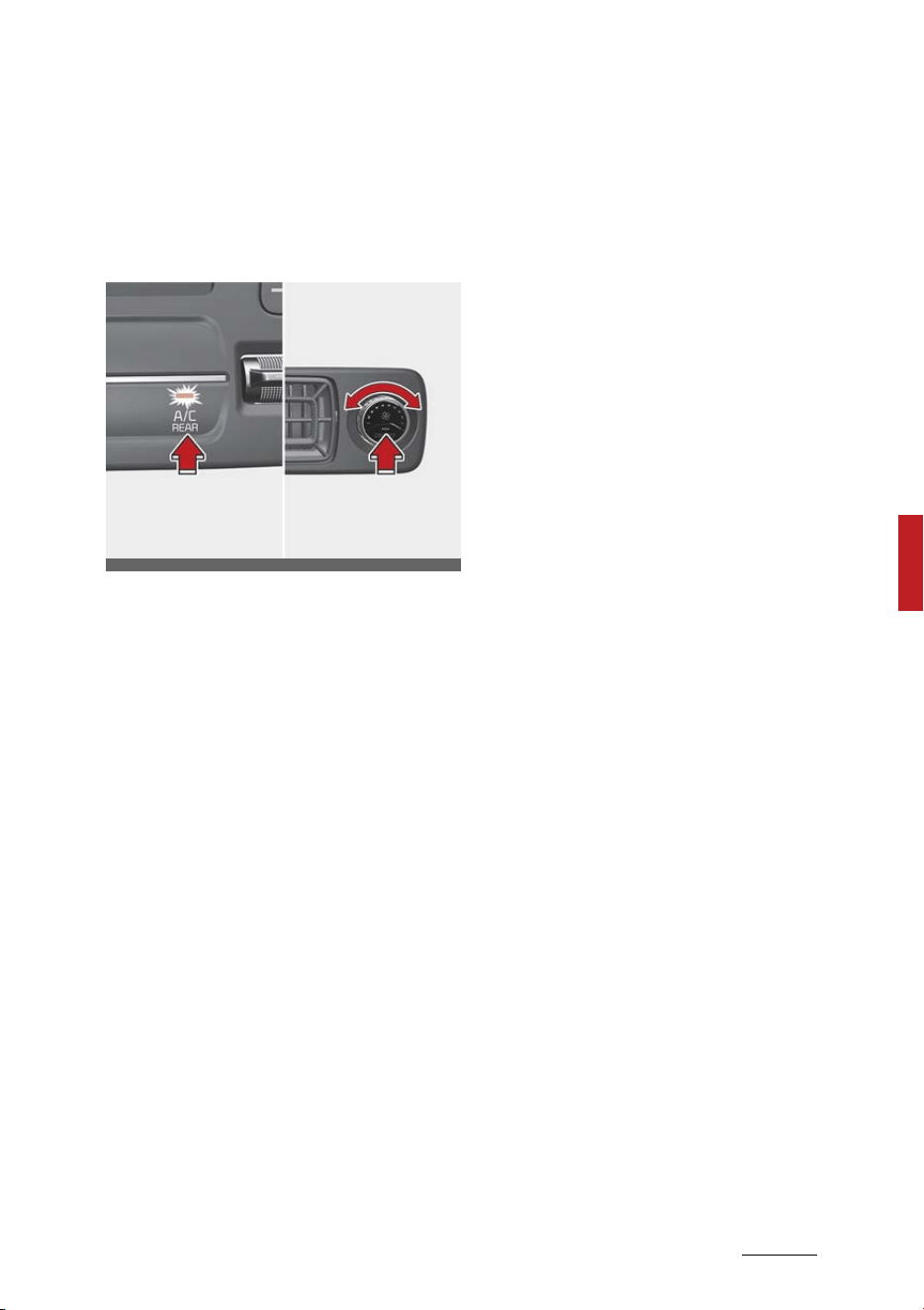
171
5
5
Features of your vehicle Automatic climate control system
START/STOP button is in the OFF
position.
3rd row air conditioning (if
equipped)
To turn on the 3rd row air condi
-
tioning control system.
1. You can operate the third row air
conditioning system from the
first row control panel. Changing
the front row's fan speed by
pressing the control button will
automatically change the third
row's fan speed as well. When the
front row air conditioning has
been turned off and you want to
stop the A/C in the third row,
press the third row air condition
-
ing select button one more time.
Then, the third row's A/C will also
turn off.
2. The third row A/C system can be
separately controlled by the con
-
trol buttons in the third row.
When the A/C is ON or OFF, the
third row A/C control button in
the front row will turn ON or OFF,
informing the front passengers of
the situation.
3. The fan speed of the third row air
conditioning can also be sepa
-
rately controlled by turning the
fan speed control knob.
OMQ4H040306L
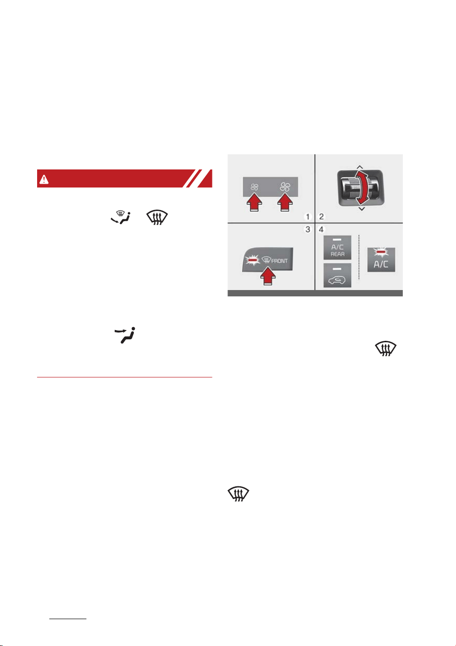
Features of your vehicle
1725
Windshield defrosting and defogging
Windshield defrosting and
defogging
When the windshield is covered with
frost or moisture, the front view is
blurred, you should remove the
frost and moisture.
WARNING
Windshield heating
Do not use the or position
during cooling operation in
extremely humid weather. The dif
-
ference between the temperature
of the outside air and the windshield
could cause the outer surface of the
windshield to fog up, causing loss of
visibility. In this case, set the mode
selection to the position and
fan speed control to the lower
speed.
䳜 For maximum defrosting, set the
temperature control to the
extreme right/hot position and
the fan speed control to the high
-
est speed.
䳜 If warm air to the floor is desired
while defrosting or defogging, set
the mode to the floor-defrost
position.
䳜 Before driving, clear all snow and
ice from the windshield, rear win
-
dow, outside rear view mirrors,
and all side windows.
䳜 Clear all snow and ice from the
hood and air inlet in the cowl grill
to improve heater and defroster
efficiency and to reduce the prob
-
ability of fogging up the inside of
the windshield.
Defogging inside windshield
1. Set the fan speed to the desired
position.
2. Select desired temperature.
3. Press the defroster button ( ).
4. The outside (fresh) air position
will be selected automatically and
the air conditioning will turn on
according to the detected ambi
-
ent temperature.
If the air conditioning and outside
(fresh) air position are not selected
automatically, adjust the corre
-
sponding button manually. If the
position is selected, lower fan
speed is adjusted to a higher fan
speed.
OMQ4040342
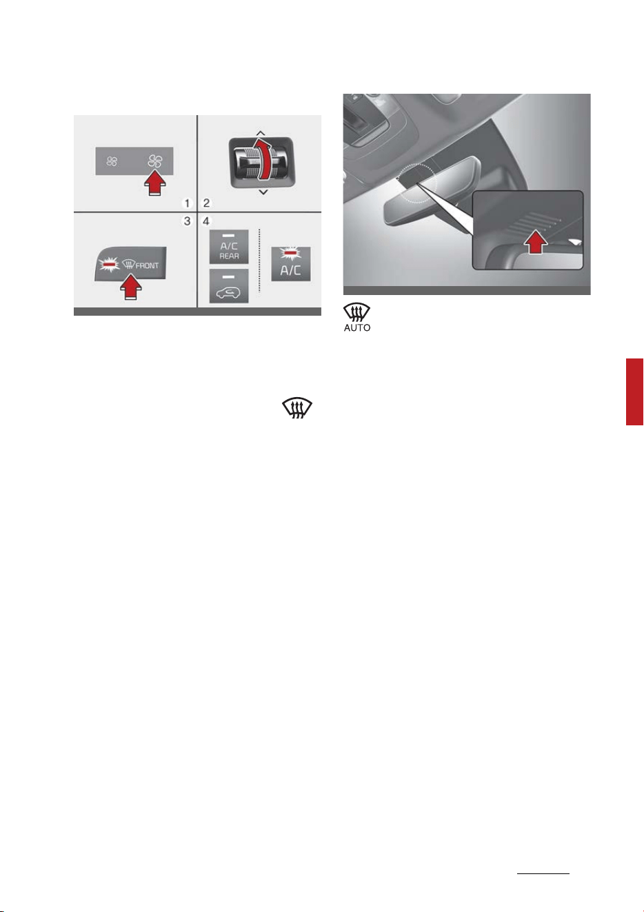
173
5
5
Features of your vehicle Windshield defrosting and defogging
Defrosting outside windshield
1. Set the fan speed to the highest
position.
2. Set the temperature to the
extreme hot (HI) position.
3. Press the defroster button ( ).
4. The outside (fresh) air position
will be selected automatically and
the air conditioning will turn on
according to the detected ambi
-
ent temperature.
Auto defogging system (if
equipped)
Auto defogging helps reduce the
possibility of fogging up the inside
of the windshield by automatically
sensing the moisture on inside the
windshield.
The auto defogging system
operates when the heater or
air conditioning is on.
When the Auto Defogging System
operates, the indicator will illumi
-
nate.
If a high amount of humidity is
detected in the vehicle, the Auto
Defogging System will be enabled.
The following steps will be per
-
formed automatically:
1. The A/C button will turn ON.
2. The air intake control will change
to Fresh mode under low outside
temperature.
3. The mode will be changed to
defrost to direct airflow to the
windshield.
4. The fan speed will be increased.
To cancel or reset the Auto Defog
-
ging System
Press the front windshield defroster
button for 3 seconds when the
ENGINE START/STOP button is in
the ON position.
OMQ4040343
OMQ4040561BR

Features of your vehicle
1745
Windshield defrosting and defogging
When the Auto Defogging System is
canceled, defrost button indicator
will blink 3 times.
When the Auto Defogging System is
reset, defrost button indicator will
blink 6 times without a signal.
NOTICE
䳜 When the air conditioning is
turned on by Auto defogging sys
-
tem, if you try to turn off the air
conditioning, the indicator will
blink 3 times and the air condi
-
tioning will not be turned off.
䳜 To maintain the effectiveness and
efficiency of the Auto Defogging
System, do not select Recircula
-
tion mode while the system is
operating.
䳜 When the Auto Defogging System
is operating, the fan speed
adjustment knob, the tempera
-
ture adjustment knob, and the air
intake control button are all dis
-
abled.
NOTICE
Do not remove the sensor cover
located on the upper end of the
driver side windshield glass.
Damage to system parts could
occur and may not be covered by
your vehicle warranty.
Defroster
The vehicle is equipped with a
defroster for removing frost or fog
from the rear window.
CAUTION
Conductors
To prevent damage to the conduc
-
tors bonded to the inside surface of
the rear window, never use sharp
instruments or window cleaners
containing abrasives to clean the
window.
If you want to defrost and defog the
front windshield, refer to "Wind
-
shield defrosting and defogging" on
page 5-172.
Operating rear window defroster
The defroster heats the window to
remove frost, fog and thin ice from
the rear window, while the engine is
on.
If there is heavy accumulation of
snow on the rear window, brush it
off before operating the rear
defroster.
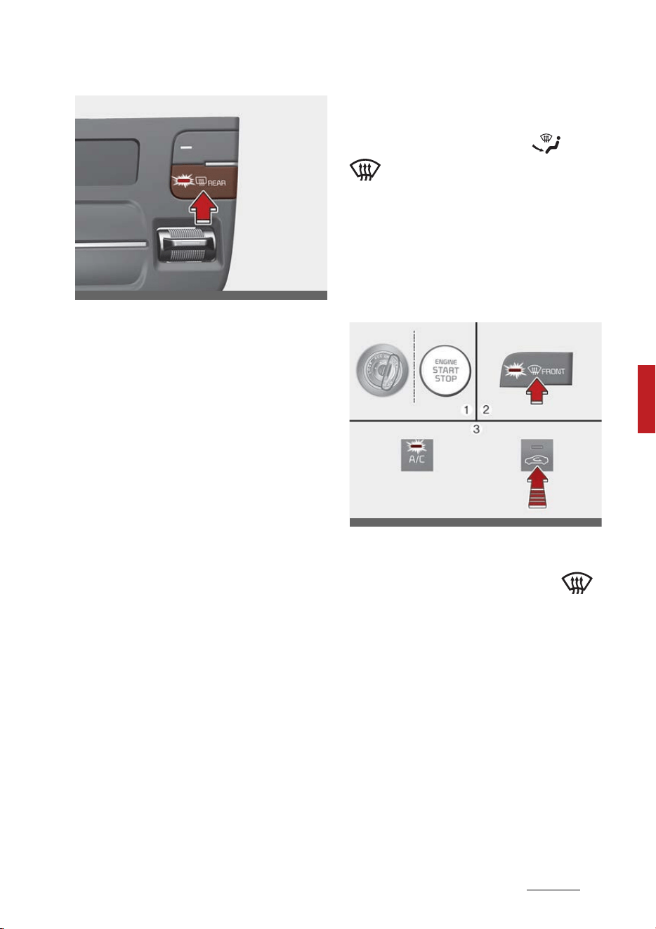
175
5
5
Features of your vehicle Windshield defrosting and defogging
To activate the rear window
defroster:
䳜 Press the rear window defroster
button located in the heater con
-
trol panel.
The indicator on the rear window
defroster button illuminates
when the defroster is ON.
The rear window defroster auto
-
matically turns off after approxi
-
mately 20 minutes or when the
ENGINE START/STOP button is
turned off.
To turn off the defroster:
䳜 Press the rear window defroster
button again.
Outside mirror defroster (if
equipped)
If your vehicle is equipped with the
outside mirror defrosters, they will
operate at the same time you turn
on the rear window defroster.
Defogging logic (if equipped)
To reduce the possibility of fogging
up the inside of the windshield, the
air intake or air conditioning is con
-
trolled automatically according to
certain conditions such as or
position.
To cancel automatic defogging logic
or return to the automatic defog
-
ging logic, do the following.
Canceling/returning automatic
defogging logic
1. Turn the ENGINE START/STOP
button to the ON position.
2. Press the defroster button ( ).
3. While pressing the air conditioning
(A/C) button, press the air intake
control button at least 5 times
within 3 seconds.
The recirculation indicator blinks 3
times in 0.5 second of intervals. It
indicates that the defogging logic
is canceled or returned to the
programmed status.
If the battery has been discharged
or disconnected, it resets to the
defog logic status.
OMQ4040332
OMQ4040345L
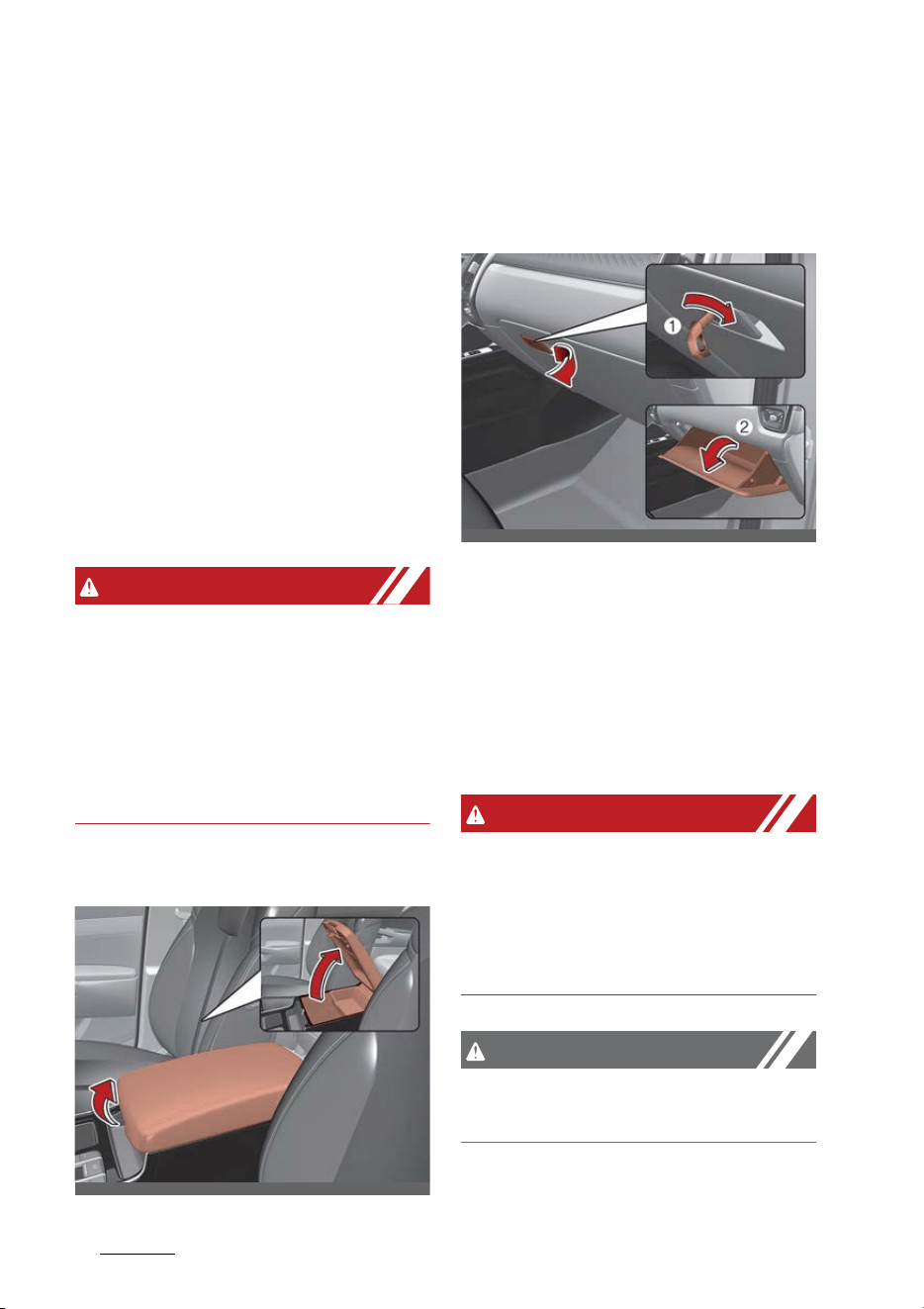
Features of your vehicle
1765
Storage compartment
Storage compartment
These compartments can be used to
store small items required by the
driver or passengers.
䳜 To avoid possible theft, do not
leave valuables in the storage
compartment.
䳜 Always keep the storage com
-
partment covers closed while
driving. Do not attempt to place
so many items in the storage
compartment that the storage
compartment cover cannot close
securely.
WARNING
Flammable materials
Do not store, propane cylinders or
other flammable/explosive materi
-
als in the vehicle. These items may
catch fire and/or explode if the vehi
-
cle is exposed to hot temperatures
for extended periods.
Center console storage
To open the center console storage:
䳜 Pull up the lever.
Glove box
The glove box can be locked and
unlocked with the mechanical key
(1).
To open the glove box:
䳜 Pull the handle and the glove box
will automatically open (2).
Close the glove box after use.
WARNING
Glove box
To reduce the risk of injury in an
accident or sudden stop, always
keep the glove box door closed while
driving.
CAUTION
Do not keep food in the glove box
for a long time.
OMQ4AH040427
OMQ4040430
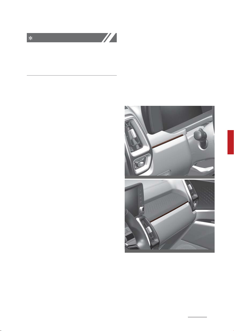
177
5
5
Features of your vehicle Interior features
NOTICE
If the temperature control switch is
in the warm or hot position, warm
or hot air will flow into the glove
box.
Interior features
There are various features inside
the vehicle for the convenience of
the occupants.
Ambient light (if equipped)
The ambient lights are applied to
the front passenger's crash pad and
front door.
OMQ4040089
OMQ4040090
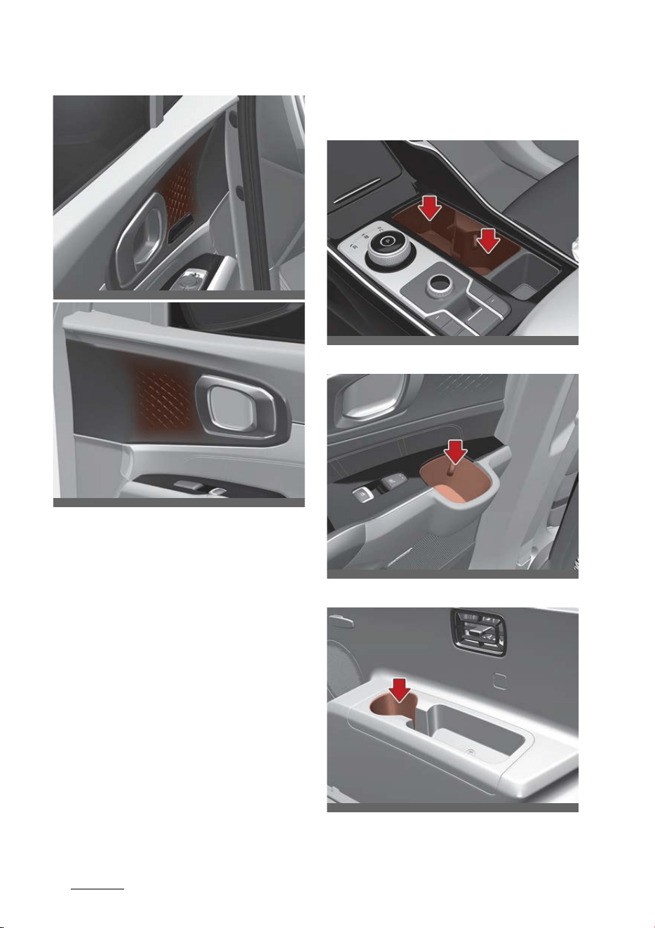
Features of your vehicle
1785
Interior features
When the headlamp light is on, the
ambient light is on at the same time
could be set in the infotainment
menu.
Refer to the infotainment manual
for details.
Cup holder
Front
Rear
3rd row seats
Cups or small beverage cans may be
placed in the cup holders.
OMQ4040423
OMQ4040424
OMQ4H040025
OMQ4040072
OMQ4040074
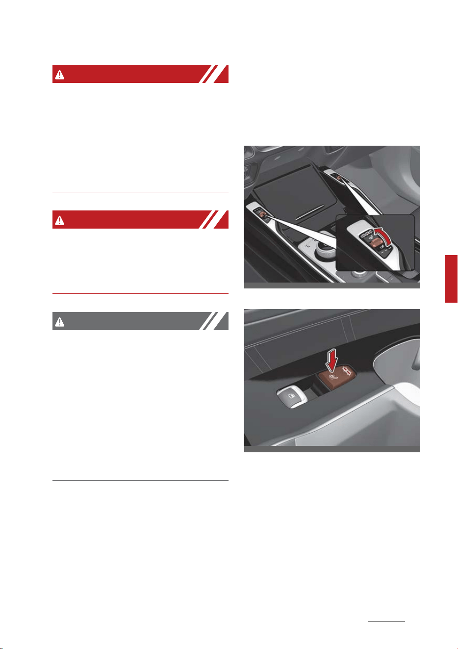
179
5
5
Features of your vehicle Interior features
WARNING
Hot liquids
Do not place uncovered cups with
hot liquid in the cup holder while the
vehicle is in motion. If the hot liquid
spills, you may burn yourself. Such a
burn to the driver could lead to loss
of control of the vehicle.
WARNING
Keep cans or bottles out of direct
sun light and do not put them in a
vehicle that is heated up. It may
explode.
CAUTION
䳜 Keep your drinks sealed while
driving to prevent spilling your
drink. If liquid spills, it may get
into the vehicle's electrical/elec
-
tronic system and damage elec
-
trical/electronic parts.
䳜 When cleaning spilled liquids, do
not use heat to dry the cup hold
-
ers. This may damage the cup
holder.
Seat warmer (if equipped)
The seat warmer is provided to
warm the front seats during cold
weather.
Front seat
Rear seat
With the ENGINE START/STOP
button in the ON position:
䳜 Push either of the levers/switch
to warm the driver's seat or the
front passenger's seat.
OMQ4H040027
OMQ4AH040083
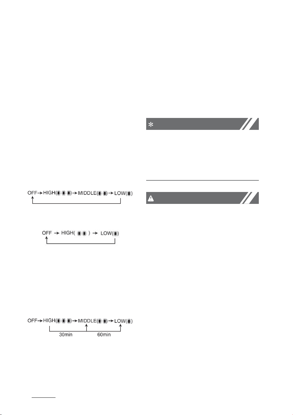
Features of your vehicle
1805
Interior features
During mild weather or under condi
-
tions where the operation of the
seat warmer is not needed, keep
the levers/switch in the "OFF" posi
-
tion.
The seat warmer defaults to the
OFF position whenever the ENGINE
START/STOP button is in the ON
position.
Temperature control (Manual)
䳜 Each time you press the levers/
switch, the temperature setting
of the seat will change as follows:
-Front seat
- Rear seat
Temperature control (Automatic)
The seat warmer starts to auto
-
matically control the seat tempera
-
ture in order to prevent low-
temperature burns after being
manually turned ON.
You may manually press the button
to increase the seat temperature.
However, it soon returns to the
automatic mode again.
䳜 When pressing the levers/switch
for more than 1.5 seconds with
the seat warmer operating, the
seat warmer will turn OFF.
NOTICE
With the seat warmer levers/switch
in the ON position, the heating sys
-
tem in the seat turns off or on
automatically depending on the seat
temperature.
CAUTION
䳜 When cleaning the seats, do not
use an organic solvent such as
paint thinner, benzene, alcohol
and gasoline. Doing so may dam
-
age the surface of the heater or
seats.
䳜 To prevent overheating the seat
warmer, do not place anything on
the seats that insulates against
heat, such as blankets, cushions
or seat covers while the seat
warmer is in operation.
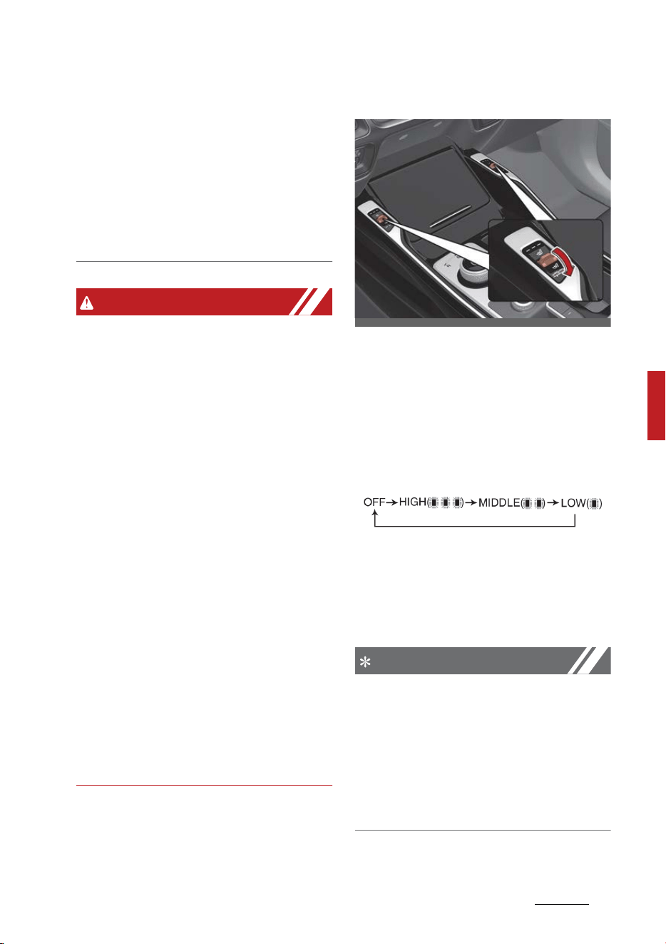
181
5
5
Features of your vehicle Interior features
䳜 Do not place heavy or sharp
objects on seats equipped with
seat warmers. Damage to the
seat warming components could
occur.
䳜 Do not change the seat cover. It
may damage the seat warmer or
air ventilation system.
WARNING
Seat warmer burns
Passengers should use extreme
caution when using seat warmers
due to the possibility of excess
heating or burns. The seat warmer
may cause burns even at low tem
-
peratures, especially if used for long
periods of time. In particular, the
driver must exercise extreme care
for the following types of passen
-
gers:
1. Infants, children, elderly or handi
-
capped persons, or hospital out
-
patients
2. Persons with sensitive skin or
those that burn easily
3. Fatigued individuals
4. Intoxicated individuals
5. Individuals taking medication that
can cause drowsiness or sleepi
-
ness (sleeping pills, cold tablets,
etc.)
Air ventilation seat (if equipped)
The temperature setting of the seat
changes according to the levers
position.
䳜 To ventilate your seat cushion,
push the levers.
Each time you push the levers,
the airflow will change as follows:
The seat warmer (with air ventila
-
tion) defaults to the OFF position
whenever the ENGINE START/STOP
button is turned on.
NOTICE
This function is designed to auto
-
matically change the temperature
setting of the seat (High -> Low) to
maintain maximum comfort inside
in case the engine is stopped by ISG
(Idle Stop and Go) system (if
equipped).
OMQ4H040028
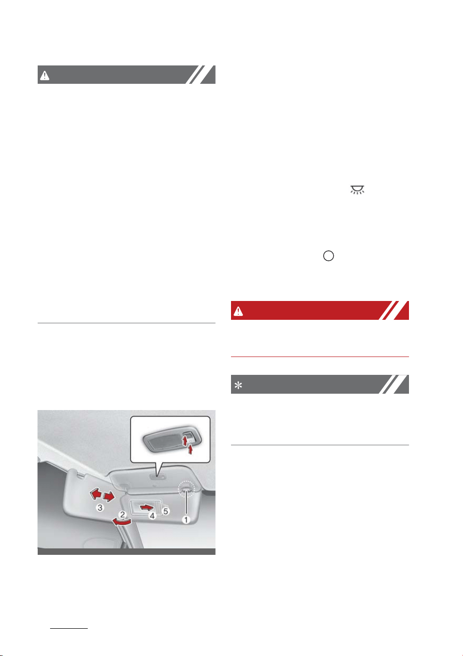
Features of your vehicle
1825
Interior features
CAUTION
Seat damage
䳜 When cleaning the seats, do not
use an organic solvent such as
paint thinner, benzene, alcohol
and gasoline. Doing so may dam
-
age the air ventilation seat.
䳜 Do not place heavy or sharp
objects on the seat. Those things
may damage the air ventilation
seat.
䳜 Be careful not to spill liquid such
as water or beverages on the
seat. If you spill some liquid, wipe
the seat with a dry towel. Before
using the air ventilation seat, dry
the seat completely.
Sun visor
Use the sun visor to shield direct
light through the front or side win
-
dows.
䳜 To use the sun visor, pull it down
-
ward.
䳜 To use the sun visor for the side
window, pull it downward, unsnap
it from the bracket (1) and swing
it to the side (2). You can slide the
sun visor if necessary (3) (if
equipped).
䳜 To use the vanity mirror, pull
down the visor and slide the mir
-
ror cover (4).
Press the ON button ( ) to turn
on the lamp inside the sun visor
when using a mirror. Before
returning the sun visor to the
original position, be sure to press
the OFF button ( ) to turn it off.
The ticket holder (5) is provided
for holding a tollgate ticket.
WARNING
For your safety, do not block your
view when using the sun visor.
NOTICE
Do not put several tickets in the
ticket holder at one time. This could
cause damage to the ticket holder.
OMQ4040075
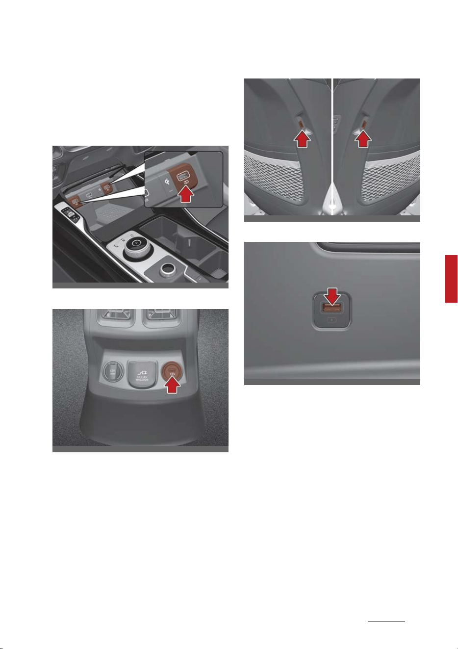
183
5
5
Features of your vehicle Interior features
USB charger (if equipped)
The USB car charger allows drivers
to charge their digital devices like
smartphones, and PC tablets.
Front
Rear
Seat (if equipped)
3rd row (if equipped)
Plug the cable into the USB port, and
charging will begin.
The USB car charger is available
with either the ACC on or the vehicle
on. We recommend you connect the
USB port and digital devices with the
engine running. See the display
screen of the device to check its
charging process completion. Your
smartphone or table PC could get
heated up while charging. This is no
reason to worry, as it doesn't
impact life or functions of the
device. For the safety reason,
OMQ4H040026
OMQ4AH040080
OMQ4040081
OMQ4040422
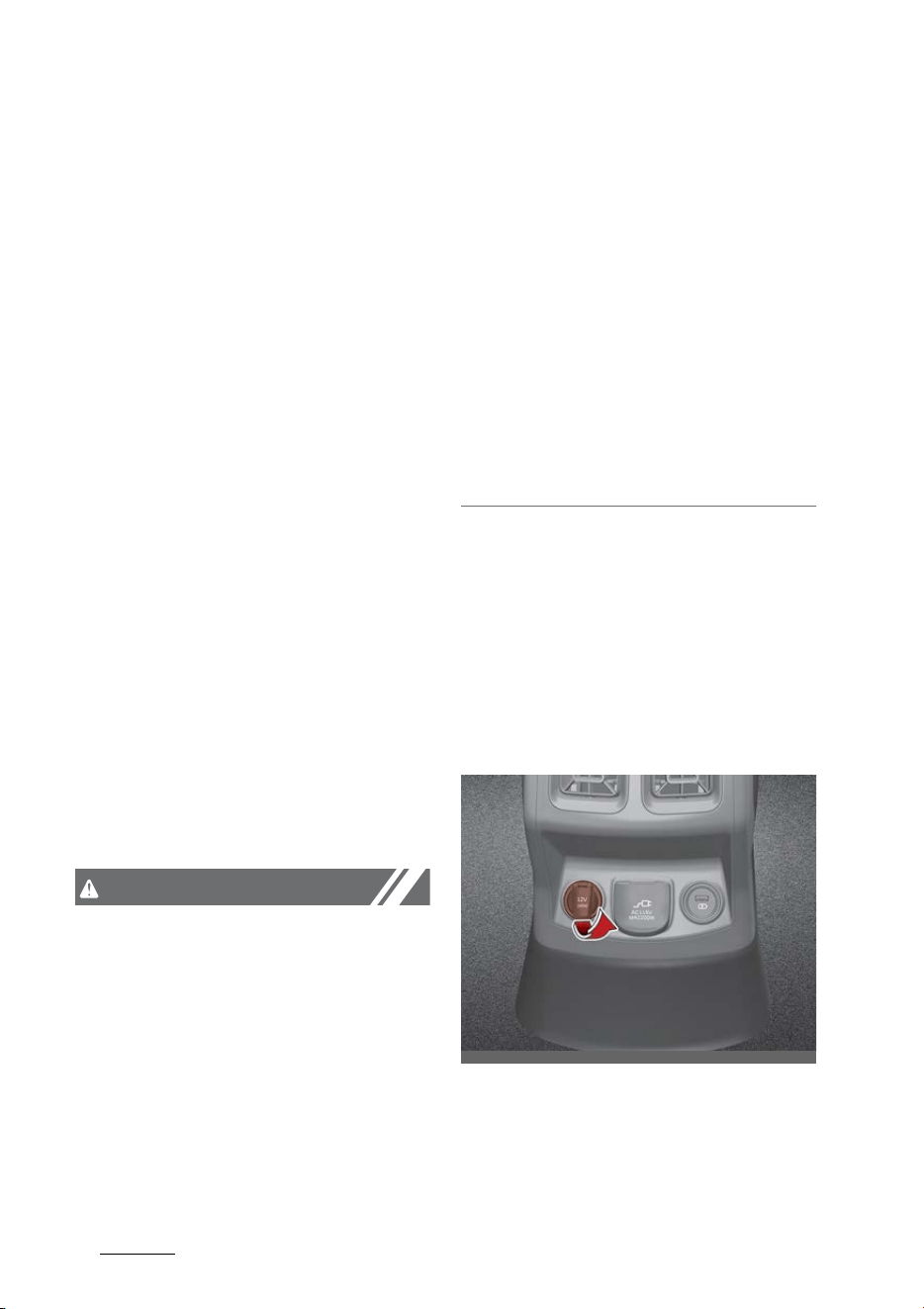
Features of your vehicle
1845
Interior features
charging can be stopped if the bat
-
tery gets heated up to a certain
point of temperature that the
devices can be negatively affected.
Charging some digital devices is not
available or requires special dedi
-
cated adapters if their charging
methods don't fit the way the USB
car charger works. Quick Charge 2.0
is available on the smart phone or
the table PC equipped with fast
charging capabilities. The applicable
is as follows: (https://www.qual
-
comm.com/documents/quick-
charge-device-list)
The smart phone or PC tablet with
-
out fast charging is charged at a
regular speed.
Rated output:
䳜 Digital devices with fast charging:
- 9.0 V, 1.67 A
䳜 Digital devices with normal
charging:
- 5.0 V, 2.1 A
CAUTION
䳜 Use the USB car charger with the
vehicle on. Otherwise, Vehicle bat
-
tery can be discharged.
䳜 Use the official USB cable of the
manufacturer of the digital device
to be charged.
䳜 Make sure that any foreign object,
drinks, and water do not come
into contact with the USB car
charger. Water or foreign object
can damage the USB charger.
䳜 Do not use the device those cur
-
rent consumption exceeds 2.1 A.
䳜 If the charger is connected incor
-
rectly, it can cause serious dam
-
age on the devices. Please note
that damages due to incorrect
usage are not covered by war
-
ranty service.
Power outlet
The power outlet is designed to
provide power for mobile tele
-
phones or other devices designed to
operate with vehicle electrical sys
-
tems.
2nd row
OMQ4AH040076
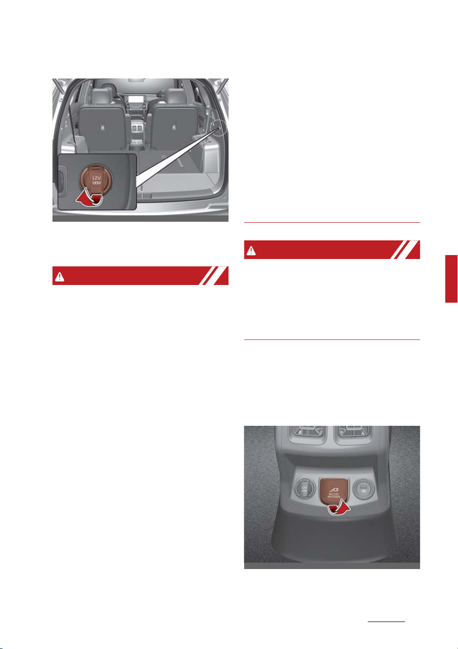
185
5
5
Features of your vehicle Interior features
3rd row (if equipped)
The devices should draw less than
15 amps with the vehicle on.
WARNING
䳜 Use the power outlet only when
the vehicle is on and remove the
accessory plug after use. Using
the accessory plug for prolonged
periods of time with the vehicle
off could cause the battery to
discharge.
䳜 Only use 12 V electric accessories
which are less than 15 A in elec
-
tric capacity.
䳜 Adjust the air-conditioner or
heater to the lowest operating
level when using the power outlet.
䳜 Close the cover when not in use.
䳜 Some electronic devices can cause
electronic interference when
plugged into a vehicle's power
outlet. These devices may cause
excessive audio static and mal
-
functions in other electronic sys
-
tems or devices used in your
vehicle.
䳜 Push the plug in as far as it will
go. If good contact is not made,
the plug may overheat and the
fuse may open.
䳜 Plug in battery equipped elec
-
tronic devices with reverse cur
-
rent protection. The current from
the battery may flow into the
vehicle's electrical/electronic sys
-
tem and cause system malfunc
-
tion.
WARNING
Electric shock
Do not put a finger or a foreign
object (pen, etc.) into a power outlet
and do not touch with a wet hand.
You may get an electric shock.
AC Inverter (if equipped)
The AC inverter supplies 115V/
150W electric power to operate
electric accessories or equipments.
OMQ4AH040078
OMQ4AH040077

Features of your vehicle
1865
Interior features
䳜 Rated Voltage: AC 115V
䳜 Maximum electric power: 150W
䳜 In order to avoid an electrical sys
-
tem failure, electric shock, etc., be
sure to read owner's manual
before use.
䳜 Be sure to close the cover except
the time of use.
WARNING
To reduce a risk of serious or fatal
injuries:
䳜 Do not use a heated electric
device such as a coffee pot,
toaster, heater, iron, etc.
䳜 Do not insert foreign objects into
the outlet and do not touch the
outlet as you may get shocked.
䳜 Do not let children touch the AC
inverter.
NOTICE
䳜 To prevent the battery from being
discharged, do not use the AC
inverter while the engine is not
running.
䳜 When not using the AC inverter,
make sure to close the AC inverter
cover.
䳜 After using an electric accessory
or equipment, pull the plug out.
Leaving the accessory or equip
-
ment plugged in for a long time
may cause battery discharge.
䳜 Do not use an electric accessory
or equipment the power con
-
sumption of which is greater than
150W (115V).
䳜 Some electric accessories or
equipments can cause electronic
interference. It may cause exces
-
sive audio noise and malfunctions
in other electric systems or
devices in the vehicle.
䳜 Do not use broken electric acces
-
sories or equipments, which may
damage the AC inverter and elec
-
trical systems of the vehicle.
䳜 Do not use two or more electric
accessories or equipments at the
same time. It may cause damage
to the electrical systems of the
vehicle.
䳜 When the input voltage is lower,
outlet LED will blink and the AC
inverter will turn off automati
-
cally. If the input voltage goes up
to normal, the AC inverter will
turn on again.
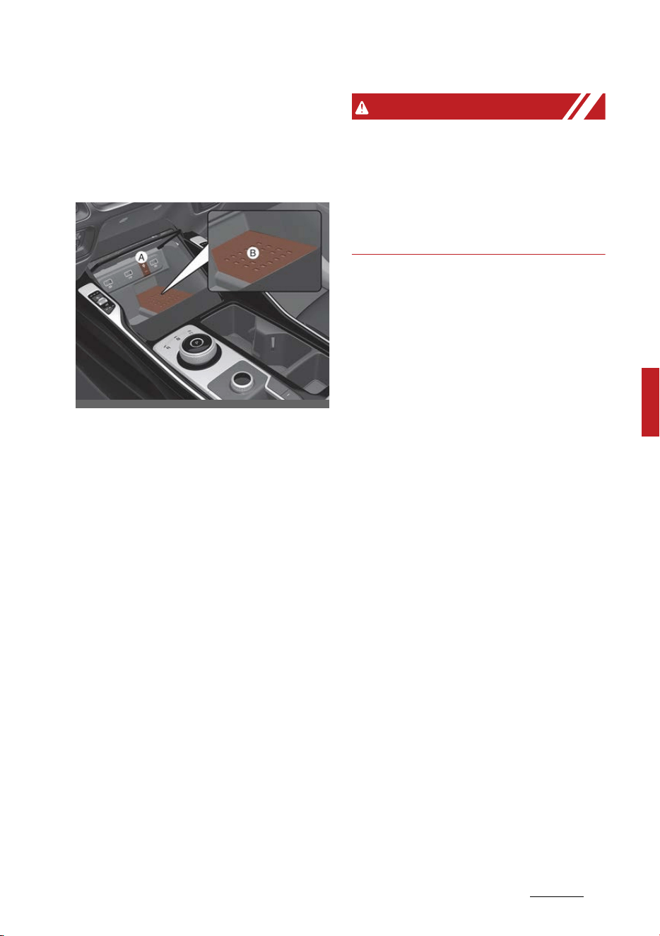
187
5
5
Features of your vehicle Interior features
Wireless smart phone charging
system (if equipped)
A wireless smart phone charging
system is located in front of the
center console.
[A]: Indicator, [B]: Charging pad
Firmly close all doors, and the
ENGINE START/STOP button is ON.
To start wireless charging, place the
smart phone equipped with wireless
charging function on the wireless
charging pad.
For best wireless charging results,
place the smart phone on the center
of the charging pad.
The wireless charging system is
designed for one smart phone
equipped with QI only. Please refer
to the smart phone accessory cover
or the smart phone manufacturer
homepage to check whether your
smart phone supports QI function.
WARNING
If any metallic object such as coins is
located between the wireless
charging system and the smart
phone, the charging may be dis
-
rupted. Also, the metallic object may
heat up.
Wireless smart phone charging
1. Remove any object on the smart
phone charging pad including the
smart key. If there is any foreign
object on the pad other than a
smart phone, the wireless
charging function may not oper
-
ate properly.
2. Place the smart phone on the
center of the wireless charging
pad.
3. The indicator light will change to
orange once the wireless charging
begins. After the charging is com
-
plete, the orange light will change
to green.
4. You can choose to turn the wire
-
less charging function to either
ON or OFF by selecting the USM
on the instrument cluster. (Please
refer to "Instrument cluster" on
page 5-80 for details).
OMQ4H040029

Features of your vehicle
1885
Interior features
If the wireless charging does not
work, gently move your smart
phone around the pad until the
charging indicator light turns yellow.
Depending on the smart phone, the
charging indicator light may not
turn green even after the charging
is complete.
If the wireless charging is not func
-
tioning properly, the orange light
will blink and flash for ten seconds
then turn off. In such cases, remove
the smart phone from the pad and
replace it on the pad again, or dou
-
ble check the charging status.
If you leave the smart phone on the
charging pad when the vehicle is
OFF, the vehicle will alert you
through warning messages and
sound (applicable for vehicles with
voice guidance function) after the
'Good bye' function on the instru
-
ment cluster ends.
For some manufacturers' smart
phones, the system may not warn
you even though the smart phone is
left on the wireless charging unit.
This is due to the particular charac
-
teristic of the smart phone and not
a malfunction of the wireless
charging.
WARNING
Distracted driving
Driving while distracted can result in
a loss of vehicle control that may
lead to an accident, severe bodily
injury, or death. The driver's pri
-
mary responsibility is in the safe
and legal operation of a vehicle. Any
use of handheld devices, other
equipment, or vehicle systems that
take the driver's eyes, attention,
and focus away from the safe oper
-
ation of a vehicle are not permissa
-
ble by law. These should never be
used during the operation of the
vehicle.
CAUTION
Liquid in wireless charging system
To prevent liquid from damaging the
wireless smart phone charging sys
-
tem in your vehicle, be sure not to
spill liquid over the charging system.

189
5
5
Features of your vehicle Interior features
CAUTION
Metal in wireless charging system
If any metallic object such as a coin
is located between the wireless
charging system and the smart
phone, the charging may be dis
-
rupted. Also, the metallic object may
heat up and potentially damage the
charging system. If there is any
metallic object between the smart
phone and the charging pad, imme
-
diately remove the smart phone.
Remove the metallic object after it
has cooled down.
CAUTION
䳜 When the interior temperature of
the wireless charging system
rises above a set temperature,
the wireless charging will cease to
function. After the interior tem
-
perature drops below the thresh
-
old, the wireless charging function
will resume.
䳜 The wireless charging may not
function properly when there is a
heavy accessory cover on the
smart phone.
䳜 The wireless charging will stop
when using the wireless smart
key search function to prevent
radio wave disruption.
䳜 The wireless charging will stop
when the smart key is moved out
of the vehicle with the vehicle in
ON.
䳜 The wireless charging will stop
when any of the doors are opened
(applicable for vehicles equipped
with smart keys).
䳜 The wireless charging will stop
when the vehicle is turned OFF.
䳜 The wireless charging will stop
when the smart phone is not in
complete contact with the wire
-
less charging pad.
䳜 Items equipped with magnetic
components such as credit card,
telephone card, bankbook or any
transportation ticket may
become damaged during wireless
charging.
䳜 Place the smart phone on the
center of the charge pad for best
results. The smart phone may not
charge when placed near the rim
of the charging pad. When the
smart phone does get charged, it
may heat up excessively.
䳜 For smart phones without built-in
wireless charging system, an
appropriate accessory has to be
equipped in order to use the vehi
-
cle's wireless charging system.
䳜 Certain smart phones may display
messages on a weak current. This
is due to the particular character
-
istics of that smart phone, and
does not imply a malfunction of
the wireless charging function.
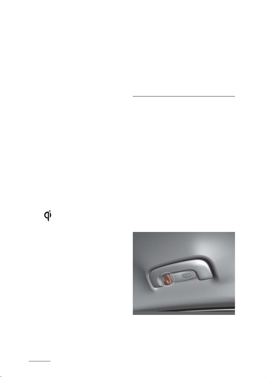
Features of your vehicle
1905
Interior features
䳜 The indicator light of some manu
-
facturers' smart phones may still
be orange after the smart phone
is fully charged. This is due to the
particular characteristic of the
smart phone and not a malfunc
-
tion of the wireless charging.
䳜 When any smart phone without a
wireless charging function or a
metallic object is placed on the
charging pad, a small noise may
sound. This small noise is due to
the vehicle discerning compatibil
-
ity of the object placed on the
charging pad. It does not affect
your vehicle or the smart phone in
any way.
䳜 The wireless cellular phone
charging system may not support
certain cellular phones, which are
not verified for the Qi specifica
-
tion ( ).
䳜 When placing your smart phone
on the charging pad, position the
phone in the middle of the pad for
maximum efficiency.
If your smart phone is off to the
side, the charging speed may slow
down, and in some cases, your
phone may experience higher
heat conduction.
䳜 When charging some smart
phones with a self-protection
feature, the wireless charging
speed may decrease, and the
charging may stop.
䳜 A smart phone that supports the
wireless charging can only be
charged wireless.
䳜 The wireless charging pad has an
internal cooling system which can
create noise to keep your phone
cool while it charges.
This device complies with part 15
of the FCC Rules
Operation is subject to the following
two conditions:
1. This device may not cause harm
-
ful interference.
2. This device must accept any
interference received, including
interference that may cause
undesired operation.
Coat hook
A Coat hook is next to the rear grab
handle.
* This actual feature may differ
from the illustration.
OMQ4040086
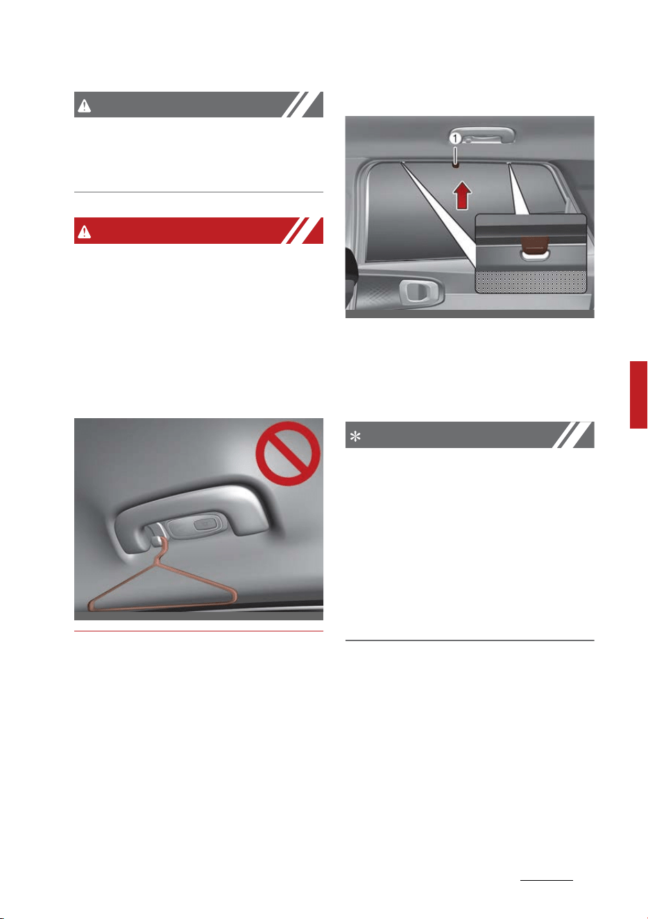
191
5
5
Features of your vehicle Interior features
CAUTION
Hanging clothing
Do not hang heavy clothes, since
they may damage the hook.
WARNING
Do not hang other objects such as
hangers or hard objects except
clothes. Also, do not put heavy,
sharp or breakable objects in the
clothing's pockets. In an accident or
when the curtain air bag is inflated,
it may cause vehicle damage or
body injury.
Side curtain (if equipped)
To use the side curtain:
1. Lift the curtain by the knob (1).
2. Hang the curtain on both sides of
the hook.
NOTICE
䳜 Always hang both sides of the
curtain on the hook. This could
cause damage to the side curtain
if only one side of the curtains is
hooked.
䳜 Do not let any foreign materials
get in between the door trim and
side curtain. The side curtain may
not be lifted up.
OMQ4040469
OMQ4040421
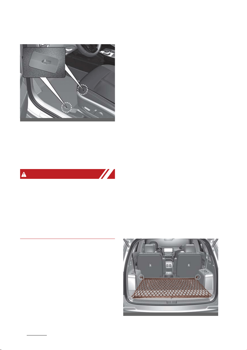
Features of your vehicle
1925
Interior features
Floor mat anchors (if equipped)
When using a floor mat on the front
floor carpet, make sure it attaches
to the floor mat anchors in your
vehicle. This keeps the floor mat
from sliding forward.
WARNING
After market floor mat
Do not install after market floor
mats that are not capable of being
securely attached to the vehicle's
floor mat anchors.
Unsecured floor mats can interfere
with pedal operation.
The following must be observed
when installing ANY floor mat to the
vehicle.
䳜 Ensure that the floor mats are
securely attached to the vehicle's
floor mat anchor(s) before driv
-
ing the vehicle.
䳜 Do not use ANY floor mat that
cannot be firmly attached to the
vehicle's floor mat anchors.
䳜 Do not stack floor mats on top of
one another (e.g., all-weather
rubber mat on top of a carpeted
floor mat). Only a single floor mat
should be installed in each posi
-
tion.
Luggage net holder
To keep items from shifting in the
cargo area, you can use the 4 hold
-
ers located in the cargo area to
attach the luggage net (if equipped),
or you can fold the luggage net into
half and attach it upwards by using
the additional 2 holders located on
each side.
OMQ4AH040472
OMQ4AH040462
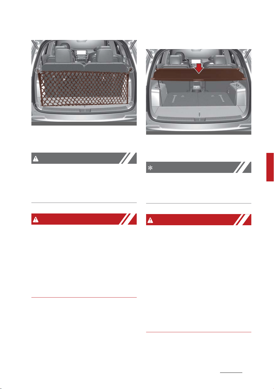
193
5
5
Features of your vehicle Interior features
If necessary, contact an authorized
Kia dealer.
CAUTION
To prevent damage to the goods or
the vehicle, be careful when carrying
fragile or bulky objects in the lug
-
gage compartment.
WARNING
DO NOT over-stretch the luggage
net and ALWAYS keep your face and
body out of the luggage net's recoil
path. Failure to comply with these
instructions may result in severe
facial injuries. DO NOT use the lug
-
gage net when the strap has visible
signs of wear or damage.
Cargo security screen (if equipped)
Use the cargo security screen to
hide items stored in the cargo area.
NOTICE
Since the cargo security screen may
be damaged or malformed, do not
put luggage on it when it is used.
WARNING
䳜 Do not place objects on the cargo
security screen. Such objects may
move around inside the vehicle
and possibly injure vehicle occu
-
pants during an accident or when
braking.
䳜 Never allow anyone to ride in the
luggage compartment. It is
designed for luggage only.
䳜 Maintain the balance of the vehi
-
cle and locate the weight as for
-
ward as possible.
OMQ4AH040413
OMQ4AH040473
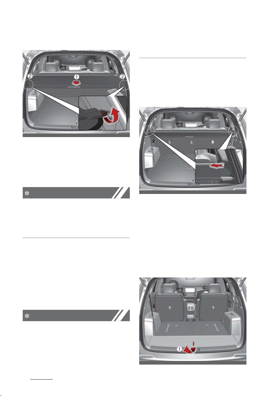
Features of your vehicle
1945
Interior features
To use the cargo security screen
1. Pull the cargo security screen
towards the rear of the vehicle by
the handle (1).
2. Insert the guide pin into the guide
(2).
NOTICE
Pull out the cargo security screen
using the handle in the center to
prevent the guide pin from falling
out of the guide.
When the cargo security screen is
not in use:
1. Pull the cargo security screen
backward and up to release it
from the guides.
2. The cargo security screen will
automatically slide back in.
NOTICE
The cargo security screen may not
automatically slide back in if the
cargo security screen is not fully
pulled out. Fully pull it out and then
let go.
To remove the cargo security
screen
1. Push the guide pin in the direction
as shown in the picture below.
2. While pushing the guide pin, pull
out the cargo security screen.
3. Keep the cargo security screen in
the guide pin above the tray.
Luggage board
The battery and the tools are
located beneath the luggage board
for easy access.
OMQ4A040561
OMQ4A040475
OMQ4AH040476
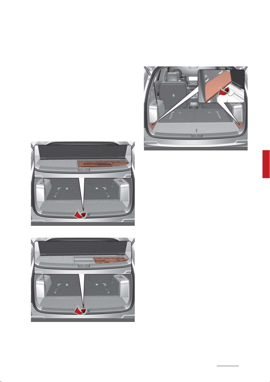
195
5
5
Features of your vehicle Interior features
1. Grasp the handle on the top of
the cover and lift it.
2. Fold the rear part of luggage
board frontward.
3. Lift up upward luggage board
frontward (Luggage board)
Luggage tray (if equipped)
You can place a first aid kit, a reflec
-
tor triangle (luggage tray), tools,
etc. in the box for easy access.
luggage tray (for hybrid vehicle)
luggage tray (for plug-in hybrid vehicle)
䳜 Grasp the handle on the top of
the cover and lift it.
Luggage side tray (if equipped)
The luggage side tray can be used
for storing small items.
䳜 To open the cover, pull up the
handle and lift the cover.
OMQ4PH040509L
OMQ4PH040489L
OMQ4AH040484
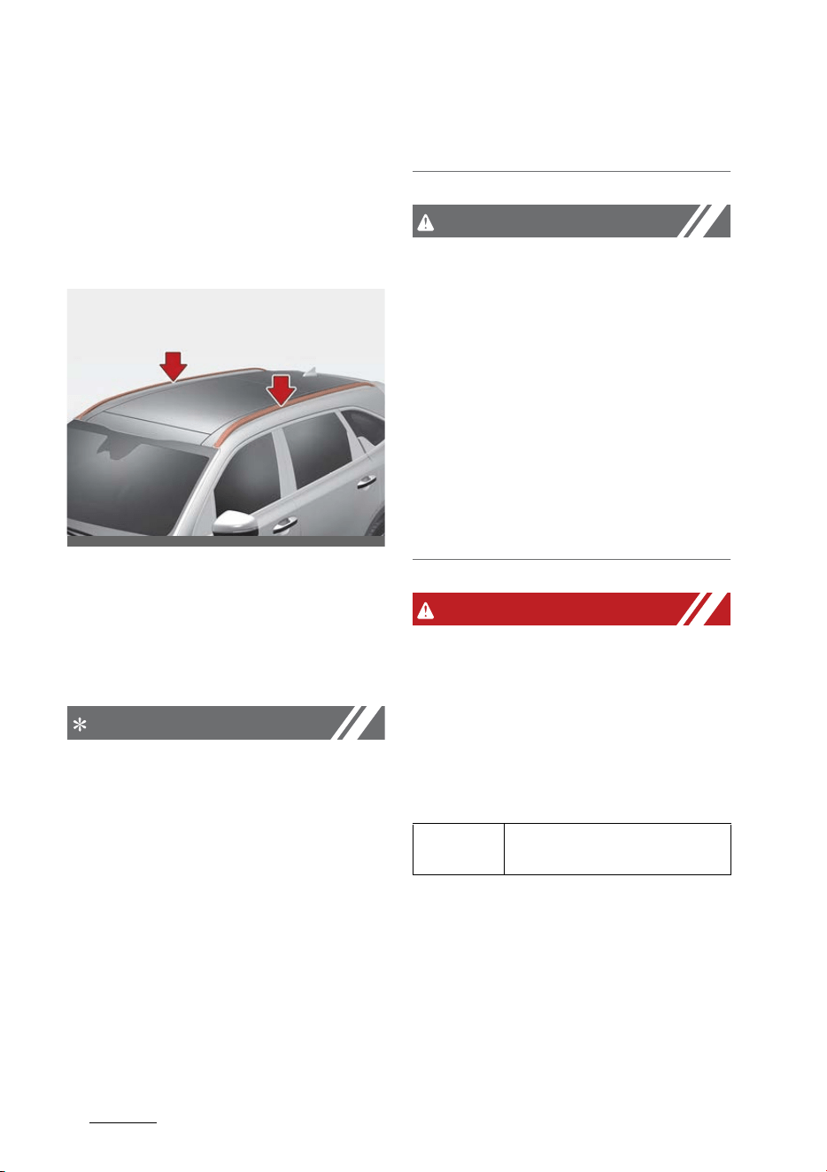
Features of your vehicle
1965
Exterior features
Exterior features
Roof rack (if equipped)
If the vehicle has a roof rack, you
can load cargo on top of your vehi
-
cle.
Crossbars and fixing components
needed to install the roof rack on
your vehicle may be obtained from
an authorized Kia dealer or other
qualified shop.
NOTICE
䳜 The crossbars (if equipped) should
be placed in the proper load car
-
rying positions prior to placing
items onto the roof rack.
䳜 If the vehicle is equipped with a
sunroof, be sure not to position
cargo onto the roof rack in such a
way that it could interfere with
sunroof operation.
䳜 When the roof rack is not being
used to carry cargo, the crossbars
may need to be repositioned if
wind noise is detected.
CAUTION
䳜 When carrying cargo on the roof
rack, take the necessary precau
-
tions to make sure the cargo does
not damage the roof of the vehi
-
cle.
䳜 When carrying large objects on
the roof rack, make sure they do
not exceed the overall roof length
or width.
䳜 When you are carrying cargo on
the roof rack, do not operate the
sunroof. (if equipped)
WARNING
䳜 The following specification is the
maximum weight that can be
loaded onto the roof rack. Distrib
-
ute the load as evenly as possible
across the crossbars (if equipped)
and roof rack and secure the load
firmly.
Loading cargo or luggage in
excess of the specified weight
limit on the roof rack may dam
-
age your vehicle.
䳜 The vehicle center of gravity will
be higher when items are loaded
onto the roof rack. Avoid sudden
starts, braking, sharp turns,
OMQ4AH040093
ROOF RACK
220 lbs. (100 kg)
EVENLY DISTRIBUTED
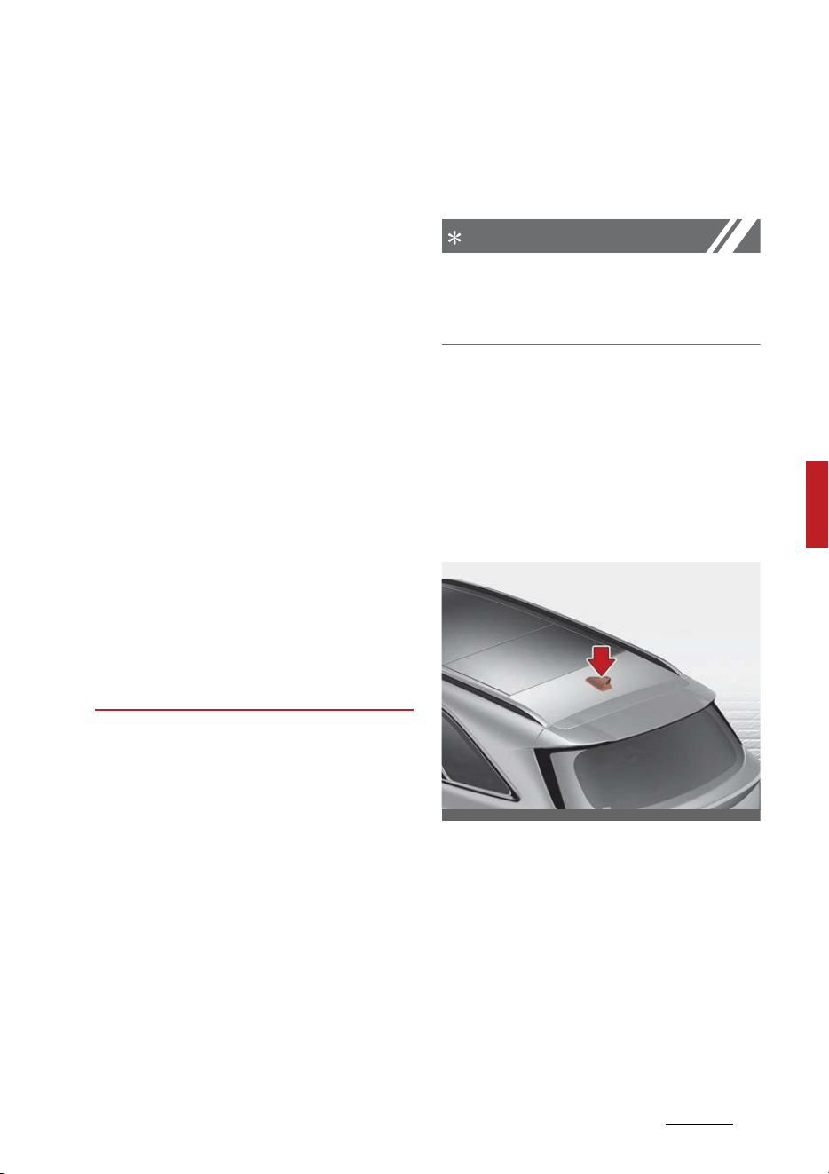
197
5
5
Features of your vehicle Infotainment system
abrupt maneuvers or high speeds
that may result in loss of vehicle
control or rollover resulting in an
accident.
䳜 Always drive slowly and turn cor
-
ners carefully when carrying
items on the roof rack. Severe
wind updrafts, caused by passing
vehicles or natural causes, can
cause sudden upward pressure on
items loaded on the roof rack.
This is especially true when car
-
rying large, flat items such as
wood panels or mattresses. This
could cause the items to fall off
the roof rack and cause damage
to your vehicle or others around
you.
䳜 To prevent damage or loss of
cargo while driving, check fre
-
quently before or while driving to
make sure the items on the roof
rack are securely fastened.
Infotainment system
Audio system
NOTICE
If you install an aftermarket HID
headlamp, your vehicle's audio and
electronic device may malfunction.
* If your vehicle is equipped with
infotainment system, refer to a
separately supplied manual for
detailed information.
Antenna
Type A
OMQ4AH041094
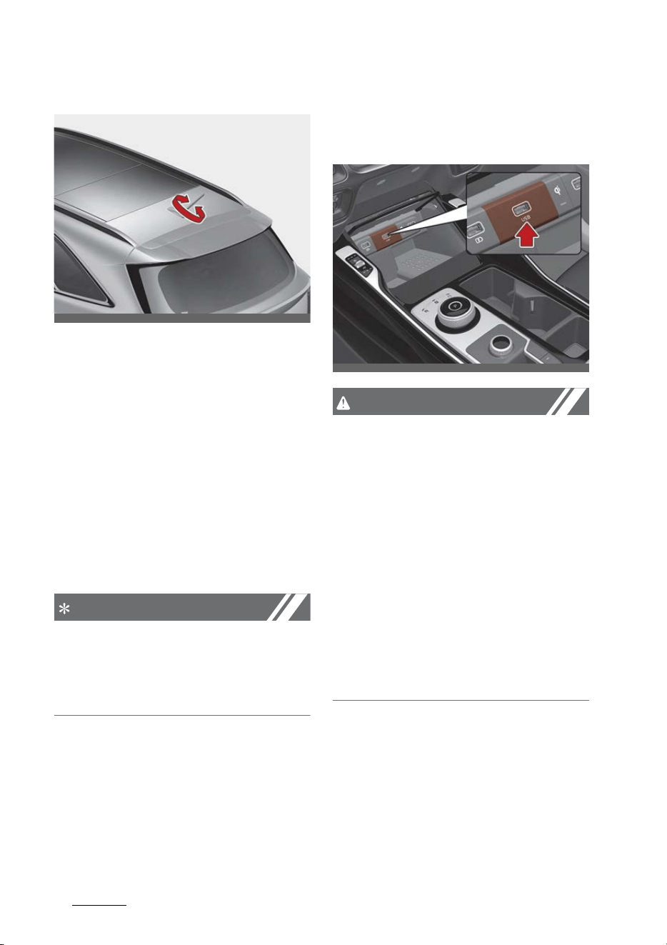
Features of your vehicle
1985
Infotainment system
Type B
1. Shark fin antenna (Type A, if
equipped)
The shark fin antenna receives
data transmitted from base sta
-
tions and satellites (e.g. AM/FM,
GPS, Sirius XM, LTE) and also
transmits to base stations (e.g.
LTE).
2. Pole antenna (Type B, if equipped)
The pole antenna receives data
transmitted from base stations
and satellites (e.g. AM/FM, GPS).
NOTICE
䳜 Avoid adding metallic coatings
such as Ni, Cd, etc. These can
degrade the receiving AM and FM
broadcast signals.
USB port
You can use the USB port to plug in
an USB.
CAUTION
Depending on the size, length, or
shape of the USB stick, if you forci
-
bly close the tray cover, the USB
device may be damaged or
deformed or the cover may not
reopen as the device is stuck.
When the stick is stuck, forcibly
opening the cover can also cause
damage to the device.
If the USB stick does not fit into the
space, do not close the cover and try
another USB stick with different
specifications.
OMQ4AH051329
OMQ4AH040096
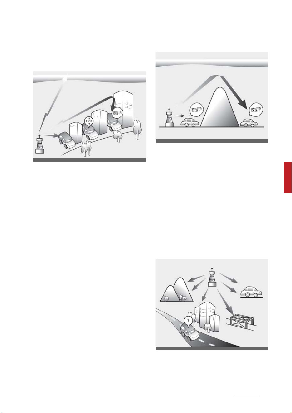
199
5
5
Features of your vehicle Infotainment system
How vehicle radio works
FM reception
AM and FM radio signals are broad
-
cast from transmitter towers
located around your city. They are
intercepted by the radio antenna on
your vehicle. This signal is then pro
-
cessed by the radio and sent to your
vehicle speakers.
However, in some cases the signal
coming to your vehicle may not be
strong and clear.
This can be due to factors, such as
the distance from the radio station,
closeness of other strong radio sta
-
tions or the presence of buildings,
bridges or other large obstructions
in the area.
AM reception
AM broadcasts can be received at
greater distances than FM broad
-
casts. This is because AM radio
waves are transmitted at low fre
-
quencies. These long distance, low
frequency radio waves can follow
the curvature of the earth rather
than traveling straight. In addition,
they curve around obstructions
resulting in better signal coverage.
FM radio station
FM broadcasts are transmitted at
high frequencies and do not bend to
follow the earth's surface. Because
ODEEV068216NR
ODEEV068217NR
ODEEV068219NR
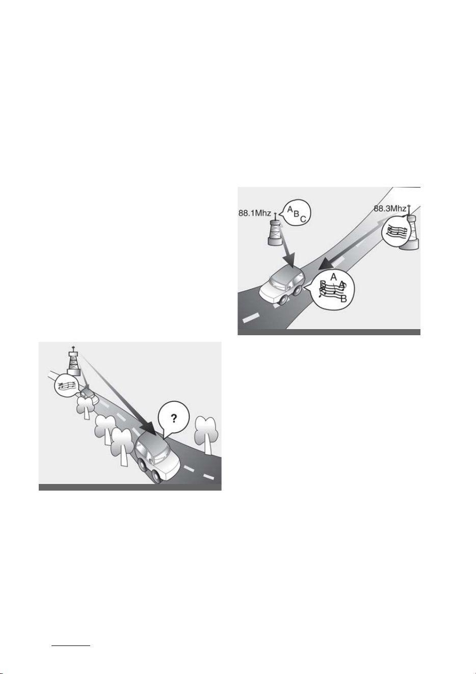
Features of your vehicle
2005
Infotainment system
of this, FM broadcasts generally
begin to fade within short distances
from the station. Also, FM signals
are easily affected by buildings,
mountains, and obstructions. This
can lead to undesirable or unpleas
-
ant listening conditions which might
lead you to believe a problem exists
with your radio.
The following conditions are normal
and do not indicate radio trouble:
䳜 Fading - As your vehicle moves
away from the radio station, the
signal will weaken and sound will
begin to fade. When this occurs,
we suggest that you select
another station with a stronger
signal.
䳜 Flutter/Static - Weak FM signals
or large obstructions between the
transmitter and your radio can
disturb the signal causing static or
fluttering noises to occur. Reduc
-
ing the treble level may lessen
this effect until the disturbance
clears.
䳜 Station Swapping - As an FM sig
-
nal weakens, another more pow
-
erful signal near the same
frequency may begin to play. This
is because your radio is designed
to lock onto the clearest signal. If
this occurs, select another station
with a stronger signal.
䳜 Multi-Path Cancellation - Radio
signals being received from sev
-
eral directions can cause distor
-
tion or fluttering. This can be
caused by a direct and reflected
signal from the same station, or
by signals from two stations with
close frequencies. If this occurs,
select another station until the
condition has passed.
OSK3048403NR
ODEEV068220NR

201
5
5
Features of your vehicle Infotainment system
Using a cellular phone or a two-
way radio
When a cellular phone is used inside
the vehicle, noise may be produced
from the audio system. This does
not mean that something is wrong
with the audio equipment. In such a
case, try to operate mobile devices
as far from the audio equipment as
possible.
When using a communication sys
-
tem such as a cellular phone or a
radio set inside the vehicle, a sepa
-
rate external antenna must be fit
-
ted. When a cellular phone or a radio
set is used with only the internal
antenna, it may interfere with the
vehicle's electrical system and
adversely affect the safe operation
of the vehicle.
WARNING
Cell phone use
Do not use a cellular phone while
driving. Stop at a safe location to
use a cellular phone.
WARNING
Distracted driving
Driving while distracted can result in
a loss of vehicle control that may
lead to an accident, severe bodily
injury, or death. The driver's pri
-
mary responsibility is in the safe
and legal operation of a vehicle. Any
use of handheld devices, other
equipment, or vehicle systems that
take the driver's eyes, attention,
and focus away from the safe oper
-
ation of a vehicle are not permissa
-
ble by law. These should never be
used during the operation of the
vehicle.

Features of your vehicle
2025
Declaration of Conformity
Declaration of Conformity
FCC
This equipment has been tested and
found to comply with the limits for a
Class B digital device, pursuant to
part 15 of the FCC Rules. These lim
-
its are designed to provide reason
-
able protection against harmful
interference in a residential installa
-
tion.
This equipment generates, uses and
can radiate radio frequency energy
and, if not installed and used in
accordance with the instructions,
may cause harmful interference to
radio communications. However,
there is no guarantee that interfer
-
ence will not occur in a particular
installation. If this equipment does
cause harmful interference to radio
or television reception, which can be
determined by turning the equip
-
ment off and on, the user is encour
-
aged to try to correct the
interference by one or more of the
following measures:
䳜 Reorient or relocate the receiving
antenna.
䳜 Increase the separation between
the equipment and receiver.
䳜 Connect the equipment into an
outlet on a circuit different from
that to which the receiver is con
-
nected.
䳜 Consult the dealer or an experi
-
enced radio/TV technician for
help.
CAUTION
Any changes or modifications to this
device that is not explicitly approved
by the manufacturer could void your
authority to operate this equip
-
ment.
This device complies with part 15 of
the FCC Rules. Operation is subject
to the following two conditions:
1. This device may not cause harm
-
ful interference.
2. This device must accept any
interference received, including
interference that may cause
undesired operation.
This equipment complies with FCC
radiation exposure limits set forth
for an uncontrolled environment.
This equipment should be installed
and operated with minimum 8 in (20
cm) between the and your body.
This transmitter must not be collo
-
cated or operating in conjunction
with any other antenna or trans
-
mitter unless authorized to do so by
the FCC.

6Driving your vehicle
Driving your vehicle
Be sure the exhaust system does not leak. ........................ 6-6
Before driving............................................................................ 6-7
ENGINE START/STOP button .................................................. 6-9
䳜 Illuminated ENGINE START/STOP button ...........................6-9
䳜 ENGINE START/STOP button position................................. 6-9
䳜 Starting the engine ..............................................................6-11
Automatic transmission (Dial SBW) ....................................6-14
䳜 Automatic transmission operation ...................................6-14
䳜 Transmission position..........................................................6-14
䳜 Good driving practices .........................................................6-20
䳜 Paddle shifter........................................................................6-21
All Wheel Drive (AWD) system..............................................6-22
䳜 AWD (AWD/SNOW MODE)....................................................6-23
䳜 For safe All Wheel Drive (AWD) operation........................6-25
Brake system ..........................................................................6-32
䳜 Power brakes ........................................................................ 6-32
䳜 Electronic Parking Brake (EPB) ..........................................6-34
䳜 AUTO HOLD............................................................................ 6-39
䳜 Anti-lock Brake System (ABS) ........................................... 6-42
䳜 Electronic Stability Control (ESC) system ........................6-44
䳜 Downhill Brake Control (DBC) .............................................6-47
䳜 Hill-start Assist Control (HAC) ...........................................6-49
䳜 Vehicle Stability Management (VSM) system .................6-49
䳜 Trailer Stability Assist (TSA) system ................................6-51
䳜 Brake Assist System (BAS).................................................6-51
䳜 Good braking practices........................................................6-52
Vehicle Auto Shut-off system..............................................6-53
䳜 Prerequisite for activation..................................................6-53

6 Driving your vehicle
䳜 Setting Shut-off Time .........................................................6-54
䳜 Resetting the time ...............................................................6-54
䳜 Canceling the Vehicle Auto Shut-off system ..................6-54
Drive mode integrated control system...............................6-55
䳜 Drive mode.............................................................................6-55
䳜 Smart shift on trip computer .............................................6-58
Forward Collision-Avoidance Assist (FCA)
(Front view camera only) ......................................................6-60
䳜 Forward Collision-Avoidance Assist Settings...................6-61
䳜 Forward Collision-Avoidance Assist Operation ................6-63
Forward Collision-Avoidance Assist (FCA)
(Sensor fusion) ........................................................................6-73
䳜 Forward Collision-Avoidance Assist Settings...................6-74
䳜 Forward Collision-Avoidance Assist Operation ................6-76
Lane Keeping Assist (LKA).....................................................6-89
䳜 Lane Keeping Assist Settings .............................................6-89
䳜 Lane Keeping Assist Operation ..........................................6-91
䳜 Lane Keeping Assist Malfunction and Limitations ..........6-93
Blind-Spot Collision-Avoidance Assist (BCA)......................6-95
䳜 Blind-Spot Collision-Avoidance Assist Settings...............6-98
䳜 Blind-Spot Collision-Avoidance Assist Operation ......... 6-100
䳜 Blind-Spot Collision-Avoidance Assist Malfunction
and Limitations .................................................................. 6-103
Safe Exit Warning (SEW) .................................................... 6-108
䳜 Safe Exit Warning Settings .............................................. 6-109
䳜 Safe Exit Warning Operation ........................................... 6-111
Safe Exit Assist (SEA).......................................................... 6-112
䳜 Safe Exit Assist Settings .................................................. 6-113
䳜 Safe Exit Assist Operation ............................................... 6-115

6Driving your vehicle
䳜 Safe Exit Assist Malfunction and Limitations................6-117
Manual Speed Limit Assist (MSLA) ....................................6-119
䳜 Manual Speed Limit Assist Operation .............................6-119
Intelligent Speed Limit Assist (ISLA)..................................6-122
䳜 Intelligent Speed Limit Assist Settings...........................6-122
䳜 Intelligent Speed Limit Assist Operation ........................6-123
䳜 Intelligent Speed Limit Assist Malfunction and
Limitations...........................................................................6-125
Driver Attention Warning (DAW) ........................................6-127
䳜 Driver Attention Warning Settings..................................6-127
䳜 Driver Attention Warning Operation ...............................6-128
䳜 Driver Attention Warning Malfunction and
Limitations...........................................................................6-131
Blind-Spot View Monitor (BVM) .........................................6-134
䳜 Blind-Spot View Monitor Settings ...................................6-135
䳜 Blind-Spot View Monitor Operation ................................6-135
䳜 Blind-Spot View Monitor Malfunction.............................6-135
Cruise Control (CC)................................................................6-136
䳜 Cruise Control Operation...................................................6-136
Smart Cruise Control (SCC) .................................................6-139
䳜 Smart Cruise Control Settings..........................................6-140
䳜 Smart Cruise Control Operation.......................................6-143
䳜 Smart Cruise Control Display and Control......................6-144
䳜 Smart Cruise Control Malfunction and Limitations ......6-150
䳜 This device complies with Part 15 of the FCC rules. ....6-155
䳜 Radio frequency radiation exposure information:........6-155
Navigation-based Smart Cruise Control (NSCC)..............6-156
䳜 Navigation-Based Smart Cruise Control Settings ........6-156
䳜 Function operation .............................................................6-157

6 Driving your vehicle
䳜 Limitations of Navigation-Based
Smart Cruise Control......................................................... 6-159
䳜 This device complies with Part 15 of the FCC rules. ... 6-162
䳜 Radio frequency radiation exposure information:....... 6-162
Lane Following Assist (LFA)................................................ 6-163
䳜 Lane Following Assist Settings........................................ 6-163
䳜 Lane Following Assist Operation..................................... 6-164
䳜 Lane Following Assist Malfunction and Limitations..... 6-166
Highway Driving Assist (HDA)............................................ 6-167
䳜 Highway Driving Assist Settings ..................................... 6-168
䳜 Highway Driving Assist Operation Function operation 6-169
䳜 Highway Driving Assist Malfunction and Limitations.. 6-172
Rear Cross-Traffic Collision-Avoidance Assist (RCCA) .. 6-174
䳜 Rear Cross-Traffic Collision- Avoidance Assist
Settings ............................................................................... 6-175
䳜 Rear Cross-Traffic Collision- Avoidance Assist
Operation ............................................................................ 6-177
䳜 Rear Cross-Traffic Collision- Avoidance Assist Malfunction
and Limitations .................................................................. 6-181
Reverse Parking Collision-Avoidance Assist (PCA) ......... 6-185
䳜 Reverse Parking Distance Warning Settings................. 6-186
䳜 Reverse Parking Distance Warning Operation.............. 6-187
䳜 Reverse Parking Distance Warning Malfunction
and Limitations .................................................................. 6-189
Remote Smart Parking Assist (RSPA) .............................. 6-192
䳜 Remote Smart Parking Assist Settings ......................... 6-196
䳜 Remote Smart Parking Assist Operation ...................... 6-198
䳜 Remote Operation status ................................................ 6-203

6Driving your vehicle
䳜 Remote Smart Parking Assist Malfunction
and Limitations ...................................................................6-204
Economical operation...........................................................6-208
Declaration of conformity...................................................6-209
䳜 Radio frequency radiation exposure information:........6-215
Special driving conditions ....................................................6-215
Winter driving........................................................................6-220
Trailer towing ........................................................................6-224
䳜 Hitches .................................................................................6-226
䳜 Safety chains ......................................................................6-226
䳜 Trailer brakes ......................................................................6-226
䳜 Driving with a trailer ..........................................................6-227
䳜 Maintenance when trailer towing ...................................6-230
䳜 If you do decide to pull a trailer .......................................6-230
Vehicle load limit ...................................................................6-233
䳜 Steps for Determining Correct Load Limit䳎 .................6-234
䳜 Certification label ...............................................................6-236
Vehicle weight .......................................................................6-237
䳜 Base curb weight................................................................6-237
䳜 Vehicle curb weight ............................................................6-237
䳜 Cargo weight .......................................................................6-237
䳜 GAW (Gross axle weight)...................................................6-237
䳜 GAWR (Gross axle weight rating) ....................................6-237
䳜 GVW (Gross vehicle weight) .............................................6-237
䳜 GVWR (Gross vehicle weight rating) ...............................6-237
Overloading............................................................................6-238

Driving your vehicle
66
Be sure the exhaust system does not leak.
Driving your vehicle
Be sure the exhaust system
does not leak.
The exhaust system should be
checked whenever the vehicle is
raised to change the oil or for any
other purpose.
If you hear a change in the sound of
the exhaust or if you drive over
something that strikes the under
-
neath side of the vehicle, have the
exhaust system checked as soon as
possible by an authorized Kia dealer.
WARNING
Engine exhaust
Do not inhale exhaust fumes or
leave your engine running in an
enclosed area for a prolonged time.
Exhaust fumes contain carbon mon
-
oxide, a colorless and odorless gas
that can cause unconsciousness and
death by asphyxiation.
WARNING
Open liftgate
Do not drive with the liftgate open.
Poisonous exhaust gases can enter
the passenger compartment. If you
must drive with the liftgate open
proceed as follows:
1. Close all windows.
2. Open side vents.
3. Set the air intake control at
"Fresh", the air flow control at
"Floor" or "Face", and the fan at
the highest speed.

7
6
6
Driving your vehicle Before driving
Before driving
Before getting into the vehicle, you
should examine the vehicle and its
surroundings. After getting into the
vehicle, you should check a number
of things before driving.
Before entering vehicle
䳜 Be sure that all windows, outside
mirror(s), and outside lights are
clean.
䳜 Check the condition of the tires.
䳜 Check under the vehicle for any
sign of leaks.
䳜 Be sure there are no obstacles
behind you if you intend to back
up.
Necessary inspections
Fluid levels, such as engine oil,
engine coolant, brake fluid, and
washer fluid should be checked on a
regular basis, at the exact interval
depending on the fluid. Further
details are provided in "Mainte
-
nance" on page 8-5.
WARNING
Distracted driving
Focus on the road while driving. The
driver's primary responsibility is in
the safe and legal operation of the
vehicle. Use of any hand-held
devices, other equipment or vehicle
systems that distract the driver
should not be used during vehicle
operation.
Before starting
䳜 Close and lock all doors.
䳜 Position the seat so that all con
-
trols are easily reached.
䳜 Buckle your seat belt.
䳜 Adjust the inside and outside rear
view mirrors.
䳜 Be sure that all lights work.
䳜 Check all gauges.
䳜 Check the operation of warning
lights when the ENGINE START/
STOP button is turned to the ON
position.
䳜 Release the parking brake and
make sure the brake warning light
is not on.
For safe operation, be sure you are
familiar with your vehicle and its
equipment.
WARNING
When you intend to park or stop the
vehicle with the engine on, be care
-
ful not to depress the accelerator
pedal for a long period of time. It
may overheat the engine or exhaust
system and cause fire.
WARNING
Check surroundings
Always check the surrounding areas
near your vehicle for people, espe
-

Driving your vehicle
86
Before driving
cially children, before putting a vehi
-
cle into D (Drive) or R (Reverse).
WARNING
Loose objects
Securely store items in your vehicle.
When you make a sudden stop or
turn the steering wheel rapidly,
loose objects may drop on the floor
and it could interfere with the oper
-
ation of the foot pedals, possibly
causing an accident.
WARNING
Driving under the influence
Do not drive while under the influ
-
ence of alcohol, drugs, or other
impairing substances. Drinking and
driving is dangerous. Even a small
amount of alcohol will affect your
reflexes, perceptions and judgment.
Driving while under the influence of
drugs or other impairing substances
is as dangerous as or more danger
-
ous than driving drunk.
WARNING
Proper footwear
Always wear appropriate shoes
when operating your vehicle.
Unsuitable shoes (high heels, ski
boots, sandals, etc.) may interfere
with your ability to use the brake
and accelerator pedals.
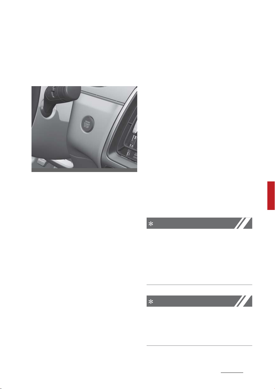
9
6
6
Driving your vehicle ENGINE START/STOP button
ENGINE START/STOP button (if
equipped)
Illuminated ENGINE START/STOP
button
The light will go off after about 30
seconds when the door is closed. It
will also go off immediately when
the theft-alarm system is armed.
ENGINE START/STOP button posi
-
tion
Your vehicle is equipped with four
different ignition positions.
OFF
To turn off the engine (START/RUN
position) or vehicle power (ON posi
-
tion), press the ENGINE START/
STOP button with the gear in the P
(Park) position. When you press the
ENGINE START/STOP button with
-
out the gear in the P (Park) position,
the ENGINE START/STOP button will
not change to the OFF position but
to the ACC position.
Anti-theft steering column lock (if
equipped)
The steering wheel locks when the
ENGINE START/STOP button is in
the OFF position to protect you
against theft.
It locks when the door is opened.
If the steering wheel is not locked
properly when you open the driver's
door, the warning chime will sound.
Try locking the steering wheel again.
If the problem is not solved, have
the system checked by an autho
-
rized Kia dealer.
In addition, if the ENGINE START/
STOP button is in the OFF position
after the driver's door is opened, the
steering wheel will not lock and the
warning chime will sound. In such a
situation, close the door. Then the
steering wheel will lock and the
warning chime will stop.
NOTICE
If the steering wheel doesn't unlock
properly, the ENGINE START/STOP
button will not work. Press the
ENGINE START/STOP button while
turning the steering wheel right and
left to release the tension.
NOTICE
You are able to turn off the engine
(START/RUN) or vehicle power (ON),
only when the vehicle is not in
motion.
OMQ4050016
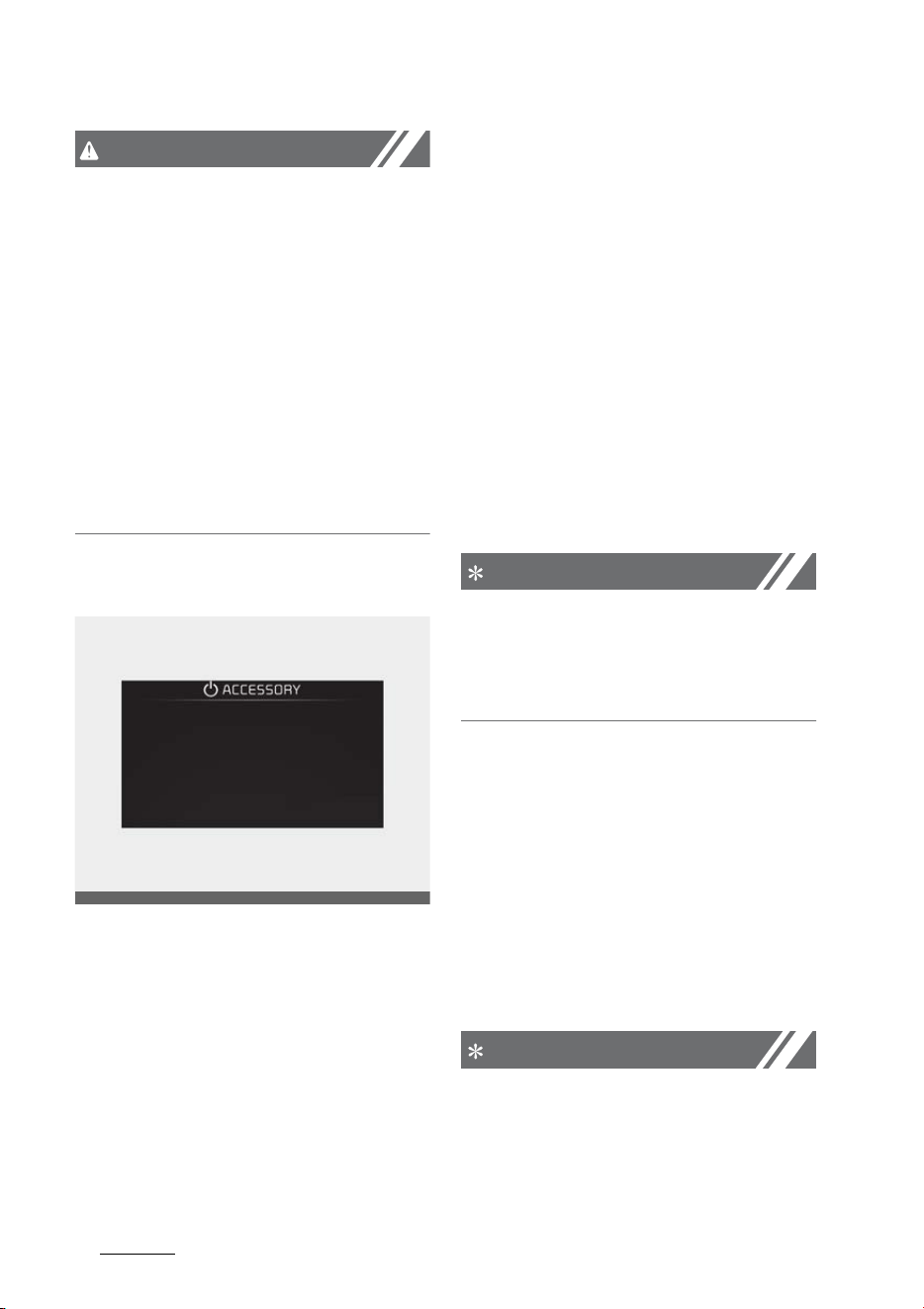
Driving your vehicle
106
ENGINE START/STOP button
CAUTION
In an emergency situation while the
vehicle is in motion, you are able to
turn the engine off and to the ACC
position by pressing the ENGINE
START/STOP button for more than 2
seconds or 3 times repeatedly
within 3 seconds.
If the vehicle is still moving, to
restart the vehicle:
䳜 Press the ENGINE START/STOP
button when vehicle speed is 3
mph (5 km/h) or over.
ACC (Accessory)
Press the ENGINE START/STOP but
-
ton while it is in the OFF position
without depressing the brake pedal.
The steering wheel unlocks and
electrical accessories are opera
-
tional.
If the ENGINE START/STOP button is
in the ACC position for more than 1
hour, the button is turned off auto
-
matically to prevent battery dis
-
charge.
ON
Press the ENGINE START/STOP but
-
ton while it is in the ACC position
without depressing the brake pedal.
The warning lights can be checked
before the engine is started. Do not
leave the ENGINE START/STOP but
-
ton in the ON position for a long
time. The battery may discharge,
because the engine is not running.
NOTICE
If you leave the ENGINE START/
STOP button in the ACC or ON posi
-
tion for a long time, the battery will
discharge.
START/RUN
To start the engine, depress the
brake pedal and press the ENGINE
START/STOP button with the gear in
the P (Park) or the N (Neutral) posi
-
tion. For your safety, start the
engine with the gear in the P (Park)
position.
NOTICE
If you press the ENGINE START/
STOP button without pressing the
brake pedal, the engine will not start
OMQ4050294L
11
6
6
Driving your vehicle ENGINE START/STOP button
and the ENGINE START/STOP button
changes as follow:
OFF → ACC → ON → OFF or ACC
WARNING
䳜 Never press the ENGINE START/
STOP button while the vehicle is in
motion. This would result in loss
of directional control and braking
function, which could cause an
accident.
䳜 Before leaving the driver's seat,
always make sure the gear is
shifted to P (Park) position, set
the parking brake fully and shut
the engine off. Unexpected and
sudden vehicle movement may
occur if these precautions are not
taken.
䳜 Never reach for the ENGINE
START/STOP button or any other
controls through the steering
wheel while the vehicle is in
motion. The presence of your
hand or arm in the area could
cause loss of vehicle control, an
accident and serious bodily injury
or death.
䳜 Do not place any movable objects
around the driver's seat as they
may move while driving, interfere
with the driver and lead to an
accident.
Starting the engine
WARNING
䳜 Do not start the vehicle with the
accelerator pedal engaged. The
vehicle can move and lead to an
accident.
䳜 Wait until the engine rpm is nor
-
mal. The vehicle may suddenly
move if the brake pedal is
released when the rpm is high.
Starting the engine with smart key
At the time that the vehicle doors
are opened or when the ENGINE
START/STOP button is pressed the
vehicle will check for the smart key.
If the smart key is not in the vehicle,
the " " indicator and a message
"Key is not in the vehicle" will appear
on the instrument cluster and LCD
window. And if all doors are closed,
the chime will sound for 5 seconds.
The indicator or warning will turn
off while the vehicle is moving.
Always have the smart key with
you.
WARNING
The engine will start, only when the
smart key is in the vehicle. Never
allow children or any person who is
unfamiliar with the vehicle touch the
ENGINE START/STOP button or
related parts. Pushing the ENGINE
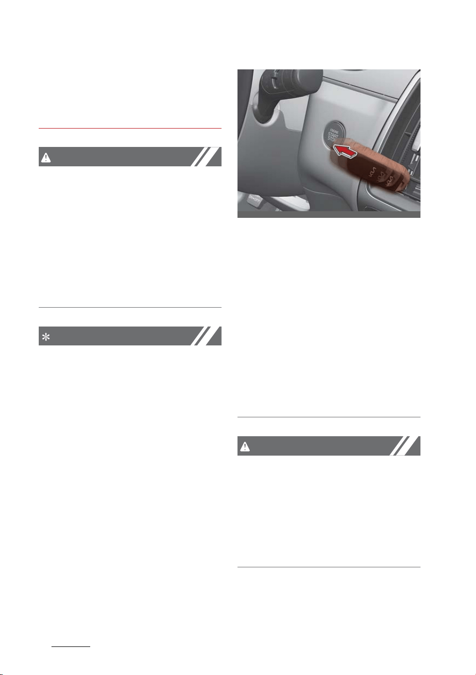
Driving your vehicle
126
ENGINE START/STOP button
START/STOP button while the smart
key is in the vehicle may result in
unintended engine activation and/or
unintended vehicle movement.
CAUTION
If the engine stalls while the vehicle
is in motion, do not attempt to
move the gear to the P (Park) posi
-
tion. If the traffic and road condi
-
tions permit, you may put the gear
in the N (Neutral) position while the
vehicle is still moving and press the
ENGINE START/STOP button in an
attempt to restart the engine.
NOTICE
䳜 If the battery is weak or the
smart key does not work cor
-
rectly, you can start the engine by
pressing the ENGINE START/STOP
button with the smart key.
When you press the ENGINE
START/STOP button directly with
the smart key, the smart key
should contact the button at a
right angle.
䳜 When the stop lamp fuse is blown,
you cannot start the engine nor
-
mally.
Replace the fuse with a new one.
If it is not possible, you can start
the engine by pressing the
ENGINE START/STOP button for
10 seconds while it is in the ACC
position. The engine can start
without pressing the brake pedal.
But for your safety always press
the brake pedal before starting
the engine.
CAUTION
䳜 Do not press the ENGINE START/
STOP button for more than 10
seconds except when the stop
lamp fuse is blown.
䳜 Do not press the ENGINE START/
STOP button with the engine run
-
ning. It may damage the starter.
OMQ4051018L

13
6
6
Driving your vehicle ENGINE START/STOP button
CAUTION
Do not press the ENGINE START/
STOP button for more than 10 sec
-
onds, except when the stop lamp
fuse is blown.
Starting the engine
1. Carry the smart key or leave it
inside the vehicle.
2. Make sure the parking brake is
firmly applied.
3. Make sure the gear is shifted to P
(Park) position. Depress the brake
pedal fully.
4. Press the ENGINE START/STOP
button.
It should be started without
depressing the accelerator pedal.
5. Do not wait for the engine to
warm up while the vehicle
remains stationary. Start driving
at moderate engine speeds.
(Steep accelerating and deceler
-
ating should be avoided.)
Starting and stopping the engine
for turbocharger intercooler
1. Do not race or accelerate the
engine immediately after start
-
ing.
If the engine is cold, idle for sev
-
eral seconds before sufficient
lubrication is ensured in the tur
-
bocharger unit.
2. After high speed or extended
driving, requiring a heavy engine
load, idle the engine about 1 min
-
ute before turning it off.
This idle time will allow the turbo
-
charger to cool prior to shutting
the engine off.
CAUTION
Do not turn the engine off immedi
-
ately after it has been subjected to
a heavy load. Doing so may cause
severe damage to the engine or tur
-
bocharger unit.
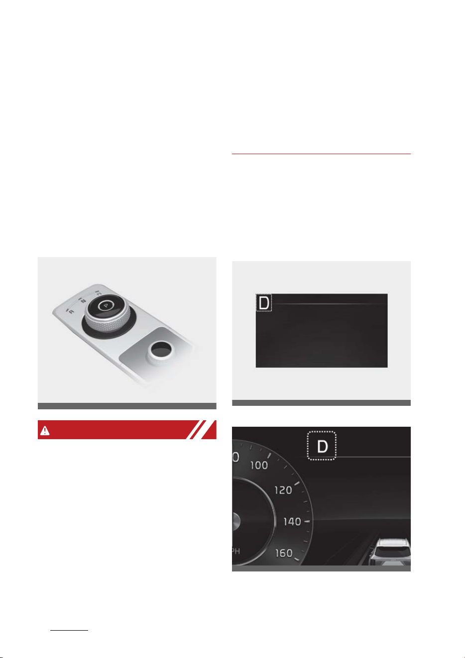
Driving your vehicle
146
Automatic transmission (Dial SBW)
Automatic transmission (Dial
SBW)
The automatic transmission has 6
forward speeds and one reverse
speed. The individual speeds are
selected automatically, depending
on the balance between the fuel
economy and the power.
Automatic transmission operation
Select transmission positions by
turning the shift dial SBW.
WARNING
Automatic transmission
To reduce the risk of serious injury
or death:
䳜 ALWAYS check the surrounding
areas near your vehicle for peo
-
ple, especially children, before
shifting a vehicle into D (Drive) or
R (Reverse).
䳜 Before leaving the driver's seat,
always make sure the gear is in
the P (Park) position, then set the
parking brake, and place the
ENGINE START/STOP button in
the OFF position. Unexpected and
sudden vehicle movement can
occur if these precautions are not
followed.
For your safety, always depress the
brake pedal while shifting to
another gear.
Transmission position
Type A
Type B
The indicator in the instrument
cluster displays the transmission
OMQ4050043
OMQ4040120
OMQ4AH051327

15
6
6
Driving your vehicle Automatic transmission (Dial SBW)
position when the ENGINE START/
STOP button is in the ON position.
P (Park)
Always come to a complete stop
before shifting into P (Park).
To shift the gear from R (Reverse),
N (Neutral) or D (Drive) to P (Park),
press the [P] button.
If you turn off the vehicle in D
(Drive), N (Neutral) or R (Reverse),
the gear automatically shifts to P
(Park).
With the vehicle on, the gear auto
-
matically shifts to P (Park) if you
open the driver's door when the
gear is in N (Neutral), R (Reverse) or
D (Drive) and the following condi
-
tions are met:
䳜 The brake/accelerator pedal is not
depressed.
䳜 The seat belt is unfastened.
䳜 The vehicle speed is below 1 mph
(2 km/h).
When the vehicle is over a certain
speed, the gear does not shift to P
(Park) when the P button is pressed.
WARNING
䳜 Shifting into P (Park) while the
vehicle is in motion may cause
you to lose control of the vehicle.
䳜 After the vehicle has stopped,
always make sure the gear is in P
(Park), apply the parking brake,
and turn the vehicle off.
䳜 Do not use the P (Park) position in
place of the parking brake.
R (Reverse)
Use this position to drive the vehicle
backward.
To shift to R (Reverse), turn the
shift dial SBW to the [R] position
while depressing the brake pedal.
CAUTION
Shifting
Always come to a complete stop
before shifting into or out of R
(Reverse); you may damage the
transmission if you shift into R
(Reverse) while the vehicle is in
motion, except on "Rocking the
vehicle" ("Rocking the vehicle" on
page 6-216).
N (Neutral)
The wheels and gear are not
engaged.
To shift to N (Neutral), turn the shift
dial SBW to the [N] position while
depressing the brake pedal.
Always depress the brake pedal
when you are shifting from N (Neu
-
tral) to another gear.
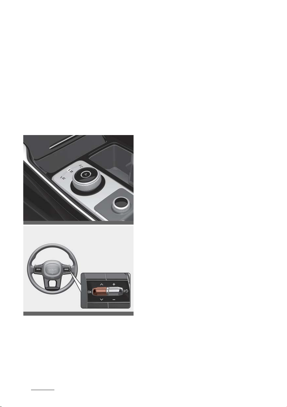
Driving your vehicle
166
Automatic transmission (Dial SBW)
In N (Neutral), if the driver attempts
to turn off the vehicle, the vehicle is
turned OFF and shifted to the P
(Park) position automatically.
Stay in N (Neutral) position when
vehicle is Off
If you want to keep the N (Neutral)
position after the vehicle is OFF, do
the following.
1. Deactivate the AUTO HOLD and
release the parking brake when
the ENGINE START/STOP button
is ON.
2. Turn the shift dial SBW to the N
(Neutral) position by depressing
the brake pedal. If the message
("Press and hold OK button to
stay in Neutral when vehicle is
Off") appears on the cluster LCD
display, press and hold the OK
button on the steering wheel for
more than 1 second. After the
message is disappeared, the vehi
-
cle will keep the N position when
the vehicle is off.
3. Turn off the engine after the
message ("Vehicle will stay in (N).
Change gear to cancel") appears
on the cluster LCD display.
In this situation, if you unfasten the
driver's seat belt and open the
driver's door within 3 minutes, the
gear shifts to P (Park) position and
the ENGINE START/STOP button is
turned off.
When the battery is discharged:
You cannot shift the shift dial SBW,
when the battery is discharged.
In emergencies, do the following to
move the shift dial SBW to N (Neu
-
tral) on a level ground.
1. Connect the battery cables from
another vehicle or from a another
battery to the jump-starting ter
-
minals inside the engine compart
-
ment. For more details, refer to
"Jump-starting" on page 7-5.
2. Release the parking brake with
the ENGINE START/STOP button
in the ON position.
3. Shift the gear to the N (Neutral)
position. If you want to keep the N
OMQ4050044
OMQ4PH051328

17
6
6
Driving your vehicle Automatic transmission (Dial SBW)
position after the vehicle is off,
disconnect the battery from vehi
-
cle or refer to "Stay in N (Neutral)
position when vehicle is Off" on
page 6-16.
CAUTION
䳜 Always park the vehicle in
"P"(Park) for safety and engage
the parking brake. If left in "N",
the vehicle may move and cause
serious damage and injury.
䳜 After the ENGINE START/STOP
button has been turned off, the
electronic parking brake cannot
be disengaged.
䳜 For EPB (Electronic Parking Brake)
equipped vehicles with AUTO
HOLD function used while driving,
if the ENGINE START/STOP button
has been turned "OFF", the elec
-
tronic parking brake will be
engaged automatically. There
-
fore, AUTO HOLD function should
be turned off before the ENGINE
START/STOP button is turned off.
D (Drive)
This is the normal driving position.
To shift to D (Drive), move the shift
dial SBW to the D (Drive) position
while depressing the brake pedal.
In D (Drive), if the driver attempts to
turn off the vehicle, the vehicle is
turned OFF and shifted to the P
(Park) position automatically.
Shift-lock system
For your safety, your vehicle has a
shift-lock system which prevents
shifting the gear from P (Park) or N
(Neutral) into R (Reverse) or D
(Drive) unless the brake pedal is
depressed.
To shift from P (Park) or N (Neutral)
into R (Reverse) or D (Drive), from R
(Reverse) into D (Drive) or from D
(Drive) into R (Reverse):
1. Depress and hold the brake pedal.
2. Start the vehicle or place the
ENGINE START/STOP button in
the ON position.
3. Turn the shift dial SBW to the R
(Reverse) or D (Drive) position.
LCD display messages
If a message appears on the LCD
display, refer to the next section for
the appropriate steps to take.
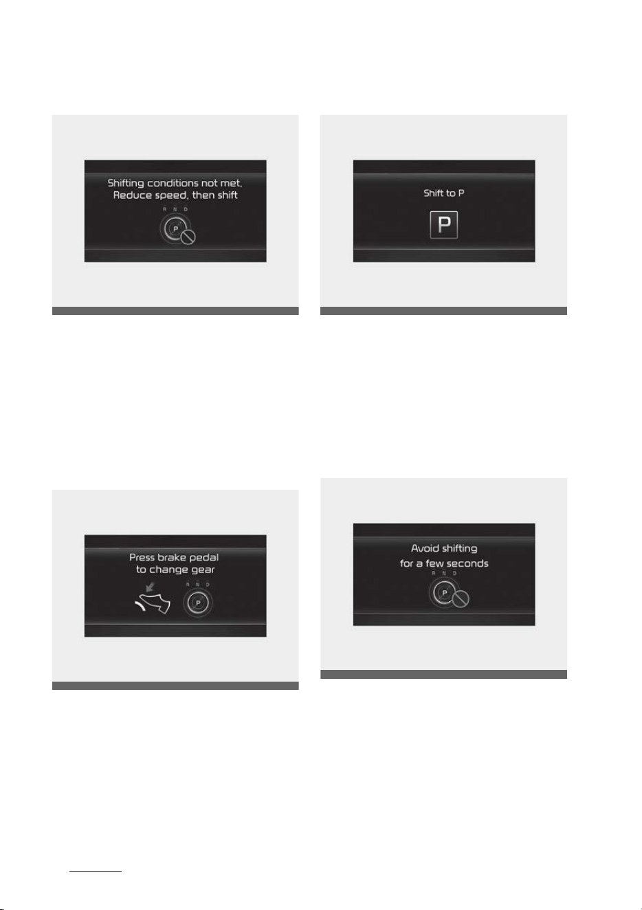
Driving your vehicle
186
Automatic transmission (Dial SBW)
Shifting conditions not met
The message appears on the LCD
display in the following conditions:
䳜 When driving speed is too fast to
shift the gear. Decrease the vehi
-
cle speed or slow down before
shifting the gear.
Press brake pedal to change gear
The message appears on the LCD
display, when the brake pedal is not
depressed while shifting the gear.
Depress the brake pedal and then
shift the gear.
Shift to P
The message appears on the LCD
display when the gear is shifted to P
(Park) while the vehicle is moving.
Stop the vehicle before shifting to P
(Park).
Gear already selected
The message appears on the LCD
display when the P gear is selected
again or the gear is overheated.
OMQ4PH051393L
OMQ4050007L
OMQ4PH051394L
OMQ4050005L
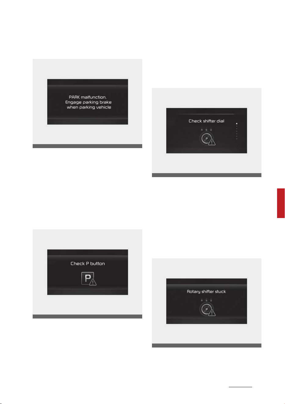
19
6
6
Driving your vehicle Automatic transmission (Dial SBW)
PARK malfunction. Engage parking
brake when parking vehicle
The message is displayed when
there is a problem with function
engaging P (Park) position.
Immediately have the vehicle
inspected by an authorized Kia
dealer.
Check P button
The message appears on the LCD
display when there is problem with
the P button.
Immediately have the vehicle
inspected by an authorized Kia
dealer.
Check shift dial SBW
The message appears on the LCD
display when there is problem with
the shift dial SBW.
Immediately have the vehicle
inspected by an authorized Kia
dealer
Rotary shifter stuck
The message appears on the LCD
display when the shift dial SBW is
OMQ4050012L
OMQ4050014L
OMQ4050013L
OMQ4050015L

Driving your vehicle
206
Automatic transmission (Dial SBW)
continuously stuck or there is prob
-
lem with the shift dial SBW.
Make sure that there is no object
around the shift dial SBW. If the
problem persists, immediately have
the vehicle inspected by an autho
-
rized Kia dealer.
When the battery (12 V) is dis
-
charged
You cannot shift the gear when the
battery is discharged.
Jump start your vehicle (refer to
"Jump-starting" on page 7-5) or
contact an authorized Kia dealer.
Good driving practices
䳜 Never move the shift dial SBW
from P (Park) or N (Neutral) to
any other position with the accel
-
erator pedal depressed.
䳜 Never move the shift dial SBW
into P (Park) when the vehicle is in
motion.
䳜 Be sure the vehicle is completely
stopped before you attempt to
shift into R (Reverse) or D (Drive).
䳜 Never take the vehicle out of gear
and coast down a hill. This may be
extremely hazardous. Always
leave the vehicle in gear when
moving.
䳜 Do not "ride" the brakes. This can
cause them to overheat and mal
-
function. Instead, when you are
driving down a long hill, slow down
and shift to a lower gear. When
you do this, engine braking will
help slow down the vehicle.
䳜 Slow down before shifting to a
lower gear. Otherwise, the lower
gear may not be engaged.
䳜 Always use the parking brake. Do
not depend on placing the trans
-
mission in P (Park) to keep the
vehicle from moving.
䳜 Exercise extreme caution when
driving on a slippery surface. Be
especially careful when braking,
accelerating or shifting gears. On
a slippery surface, an abrupt
change in vehicle speed can cause
the drive wheels to lose traction
and the vehicle to go out of con
-
trol.
䳜 Optimum vehicle performance
and economy is obtained by
smoothly depressing and releas
-
ing the accelerator pedal.
WARNING
䳜 When driving uphill or downhill,
always shift to D (Drive) for driv
-
ing forward or shift to R (Reverse)
for driving backwards, and check
the gear position indicated on the
cluster before driving. Driving in
the opposite direction of the
selected gear can lead to a dan
-
gerous situation by shutting off
the engine and affecting the
braking performance.
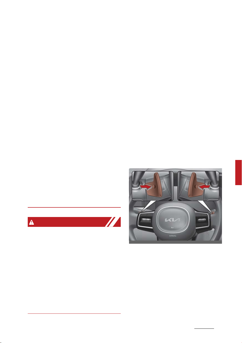
21
6
6
Driving your vehicle Automatic transmission (Dial SBW)
䳜 Always buckle-up! In a collision, an
unbelted occupant is significantly
more likely to be seriously injured
or killed than a properly belted
occupant.
䳜 Avoid high speeds when cornering
or turning.
䳜 Do not make quick steering wheel
movements, such as sharp lane
changes or fast, sharp turns.
䳜 The risk of a rollover is greatly
increased if you lose control of
your vehicle at highway speeds.
䳜 Losing control often occurs if two
or more wheels drop off the road
-
way and the driver oversteers to
reenter the roadway.
䳜 In the event your vehicle leaves
the roadway, do not steer
sharply. Instead, slow down
before pulling back into the travel
lanes.
䳜 Never exceed posted speed limits.
WARNING
If your vehicle becomes stuck in
snow, mud, sand, etc., then you may
attempt to rock the vehicle free by
moving it forward and backward. Do
not attempt this procedure if people
or objects are anywhere near the
vehicle. During the rocking operation
the vehicle may suddenly move for
-
ward or backward as it becomes
unstuck, causing injury or damage
to nearby people or objects.
Moving up a steep grade from a
standing start
To move up a steep grade from a
standing start:
1. Depress the brake pedal, shift the
shift dial SBW to D (Drive).
2. Select the appropriate gear
depending on load weight and
steepness of the grade, and
release the parking brake.
Depress the accelerator gradually
after releasing the service brakes.
Paddle shifter
The paddle shift function is available
when the shift dial SBW is in the D
(Drive) position.
With the shift dial SBW in the D
position
Pull the [+] or [-] paddle shifter once
to shift up or down one gear and the
system changes from automatic
mode to manual mode.
OMQ4051042

Driving your vehicle
226
All Wheel Drive (AWD) system
To change back to automatic shift
mode from manual shift mode, do
one of the followings:
䳜 Pull the [+] paddle shifter for
more than one second.
The manual shift mode also changes
back to automatic shift mode in one
of following situations:
䳜 When the accelerator pedal is
gently depressed for more than
approximately 6 seconds while
driving
䳜 When the vehicle speed is lower
than 2 mph (3 km/h) (after driving
more than 7 mph (10 km/h)
NOTICE
If you pull the [+] and [-] paddle
shifters at the same time, you can
-
not shift the gear.
All Wheel Drive (AWD) system (if
equipped)
The All Wheel Drive (AWD) system
delivers engine power to front and
rear wheels for maximum traction.
AWD is useful when extra traction is
required, such as when driving slip
-
pery, muddy, wet, or snow-covered
roads.
If the system determines there is a
need for four wheel drive, the
engine's driving power will be dis
-
tributed to all four wheels automat
-
ically.
WARNING
Off road driving
This vehicle is designed primarily for
on road use although it can operate
effectively off road. However, it was
not designed to drive in challenging
off-road conditions. Driving in con
-
ditions that exceed the vehicle's
intended design or the driver's
experience level may result in
severe injury or death.
NOTICE
If the AWD warning light ( ) stays
on the instrument cluster, your
vehicle may have a malfunction with
the AWD system. When the AWD
warning light ( ) illuminates, have
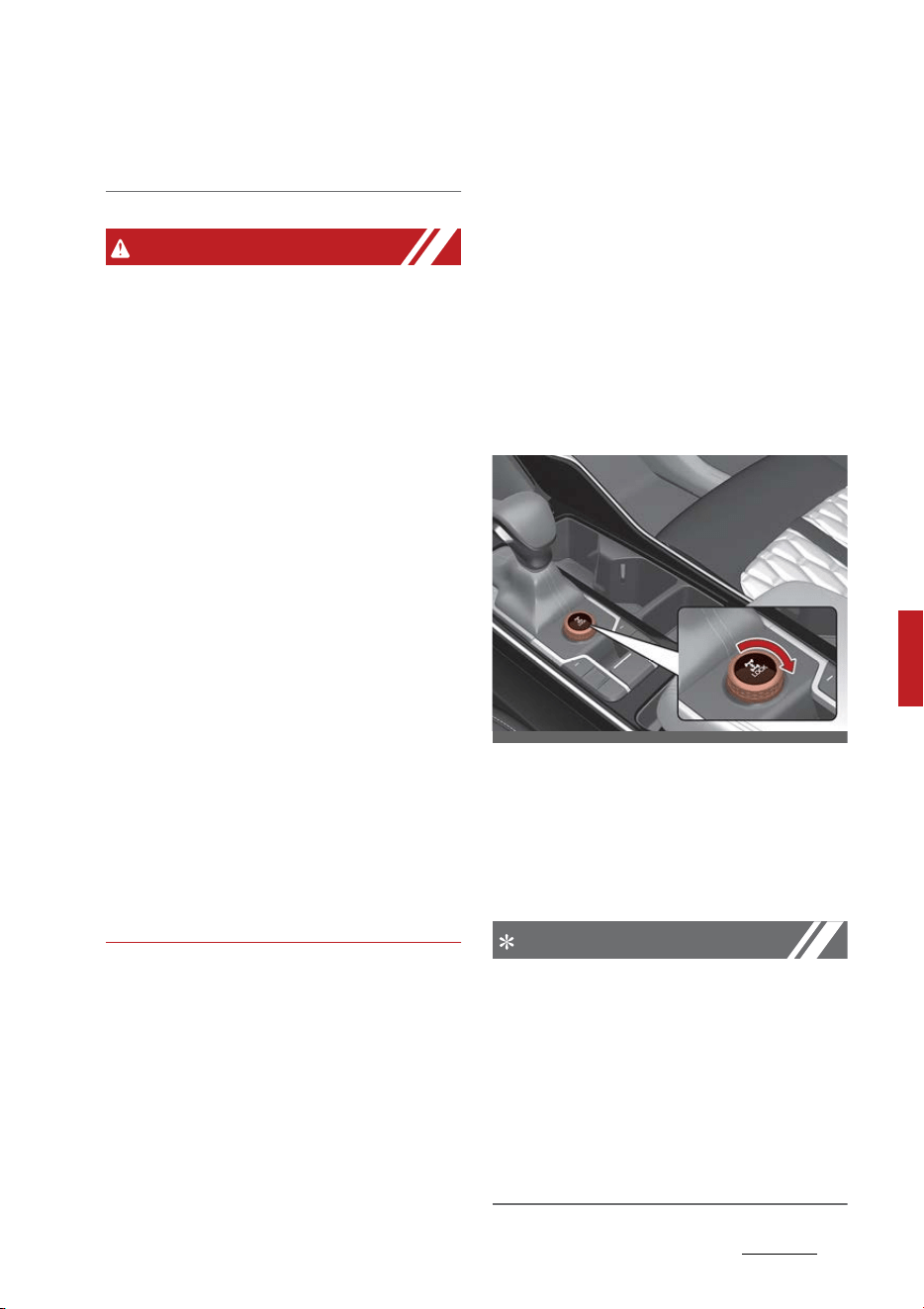
23
6
6
Driving your vehicle All Wheel Drive (AWD) system
your vehicle checked by an autho
-
rized Kia dealer.
WARNING
To reduce the risk of SERIOUS
INJURY or DEATH:
䳜 Do not drive in conditions that
exceed the vehicle's intended
design such as challenging off-
road conditions.
䳜 Avoid high speeds when cornering
or turning.
䳜 Do not make quick steering wheel
movements, such as sharp lane
changes or fast, sharp turns.
䳜 The risk of a rollover is greatly
increased if you lose control of
your vehicle at highway speeds.
䳜 Loss of control often occurs if two
or more wheels drop off the road
-
way and the driver over steers to
reenter the roadway.
䳜 In the event your vehicle leaves
the roadway, do not steer
sharply. Instead, slow down
before pulling back into the travel
lanes.
AWD (AWD/SNOW MODE)
AWD helps the vehicle to maintain
its best driving performance by con
-
trolling 4 wheels, engine, transmis
-
sion and braking according to road
conditions such as snow, mud, sand,
etc.
Advantages of AWD
䳜 Enhance safety when driving
straight.
䳜 Improve performance when cor
-
nering.
䳜 Ensure operability in tough driving
conditions such as snow, rain,
sand, etc.
Switching from/to SNOW MODE (if
equipped)
You can switch from DRIVE MODE to
SNOW mode by turning the knob. If
you turn the DRIVE/SNOW mode
button again, the vehicle will go back
to DRIVE MODE.
NOTICE
䳜 Even though you turned off the vehi
-
cle in SNOW mode, DRIVE mode will
be set when you restart the vehicle.
䳜 When the AWD LOCK mode is deacti
-
vated, a shock may be felt as the
drive power is delivered entirely to
the front wheels. This shock is not a
mechanical failure.
OMQ4A050292
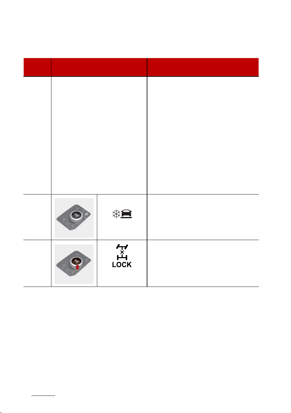
Driving your vehicle
246
All Wheel Drive (AWD) system
AWD transfer mode selection
Transfer
mode
Selection mode Description
DRIVE
MODE
-
䳜 DRIVE MODE is used when driving on
roads in normal conditions, roads in
urban areas, and on highways.
䳜 All wheels are in operation when a
vehicle travels at a constant speed.
Required tractions applying on front
and rear wheels vary depending on
road driving conditions and driving
conditions, which will be automati
-
cally controlled by the computing
system.
䳜 When the cluster's DRIVE MODE dis
-
play mode is selected, the cluster dis
-
plays the status of how four wheels'
traction forces are distributed.
SNOW
SNOW mode is used to appropriately
distribute the vehicle's traction forces
and prevent wheel slippage when driving
on snowy or slippery road.
AWD
LOCK
(Indicator light
is illuminated)
The main goal of AWD Lock mode is to
allow a driver to maximize the vehicle's
traction under extreme driving condi
-
tions such as unpaved off-road, sandy
roads, and muddy roads.
SNOW
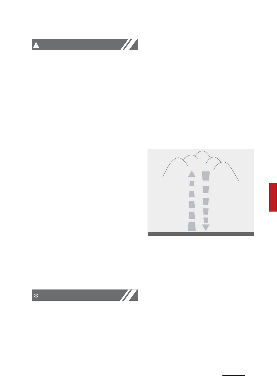
25
6
6
Driving your vehicle All Wheel Drive (AWD) system
CAUTION
Normal road conditions
䳜 Maintain DRIVE mode when driv
-
ing on roads in normal conditions.
䳜 Driving in TERRAIN mode on nor
-
mal roads may damage the AWD
system and cause mechanical
vibration or noise.
䳜 When driving under normal road
conditions (especially when cor
-
nering) in AWD Lock mode, a
driver may find minor mechanical
vibration or noise, which is
extremely normal phenomenon,
not a malfunction. When AWD
Lock mode is released, such noise
or vibration will be immediately
gone.
䳜 When you turn off AWD Lock
mode, it can lead to little shocks
but this is a normal phenomenon
that lasts until the traction forces
on the front and rear wheels of
the vehicle are released.
For safe All Wheel Drive (AWD)
operation
NOTICE
All Wheel Drive
The conditions of on-road or off-
road that demand All Wheel Drive
mean all functions of your vehicle
are exposed to extreme stress than
under normal road conditions. Slow
down and be ready for changes in
the composition and traction of the
surface under your tires. If you have
any doubt about the safety of the
conditions you are facing, stop and
consider the best way to proceed.
䳜 Do not try to drive in deep stand
-
ing water or mud since such con
-
ditions can stall your engine and
clog your exhaust pipes. Do not
drive down steep hills since it
requires extreme skill to maintain
control of the vehicle.
䳜 When you are driving up or down
hills drive as straight as possible.
Use extreme caution in going up
or down steep hills, since you may
flip your vehicle over depending
on the grade, terrain and water/
mud conditions.
OON058159NR
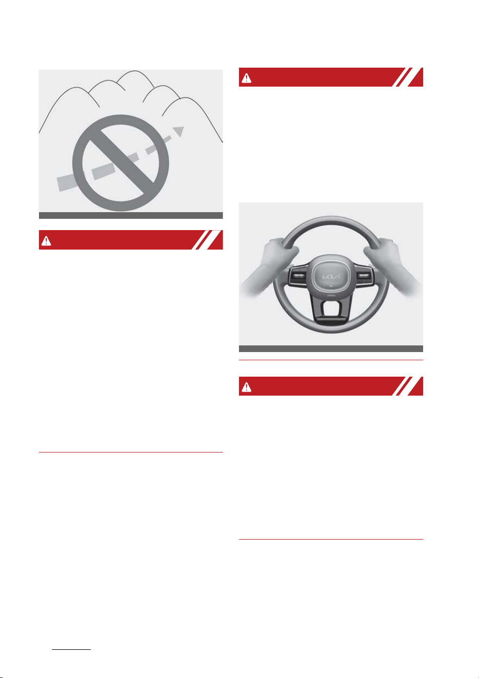
Driving your vehicle
266
All Wheel Drive (AWD) system
WARNING
Hills
Driving across the contour of steep
hills can be extremely dangerous.
This danger can come from slight
changes in the wheel angle which
can destabilize the vehicle or, even if
the vehicle is maintaining stability
under power, it can lose that stabil
-
ity if the vehicle stops its forward
motion. Your vehicle may roll over
without warning and without time
for you to correct a mistake that
could cause serious injury or death.
䳜 You must learn how to corner in a
AWD vehicle. Do not rely on your
experience in conventional FWD
vehicles when cornering the vehi
-
cle in AWD mode. For starters,
you must drive slower in AWD.
WARNING
All Wheel Drive (AWD)
Reduce speed when you turn cor
-
ners. The center of gravity of AWD
vehicles is higher than that of con
-
ventional FWD vehicles, making
them more likely to roll over when
you turn corners too fast.
WARNING
Steering wheel
Do not grab the inside of the steer
-
ing wheel when you are driving on
unpaved roads. You may hurt your
arm by a sudden steering maneuver
or from steering wheel rebound due
to impact with objects on the
ground. You could lose control of the
steering wheel.
䳜 Always hold the steering wheel
firmly when you are driving on
unpaved roads.
䳜 Make sure all passengers are
wearing seat belts.
OON058160NR
OMQ4051269L

27
6
6
Driving your vehicle All Wheel Drive (AWD) system
WARNING
Wind danger
If you are driving in heavy wind, the
vehicle's higher center of gravity
decreases your steering control
capacity and requires you to drive
more slowly.
WARNING
Driving through water
Drive slowly. If you are driving too
fast in water, the water can get into
the engine compartment and wet
the ignition system, causing your
vehicle to suddenly stop. If this hap
-
pens and your vehicle is in a tilted
position, your vehicle may roll over.
NOTICE
䳜 Do not drive in water if the level is
higher than the bottom of the
vehicle.
䳜 Check your brake condition once
you are out of mud or water.
Press the brake pedal several
times as you move slowly until
you feel normal braking forces
return.
䳜 Shorten your scheduled mainte
-
nance interval if you drive in
offroad conditions such as sand,
mud or water (refer to "Mainte
-
nance under severe usage condi
-
tions - Non Turbo Models" on
page 7-15 and "Maintenance
under severe usage conditions -
Turbo Models" on page 7-20).
Always wash your vehicle thor
-
oughly after off-road use, espe
-
cially cleaning the bottom of the
vehicle.
䳜 Since the driving torque is always
applied to the 4 wheels the per
-
formance of the AWD vehicle is
greatly affected by the condition
of the tires. Be sure to equip the
vehicle with four tires of the same
size and type.
䳜 A full time All Wheel Drive vehicle
cannot be towed by an ordinary
tow truck. Make sure that the
vehicle is placed on a flat bed
truck for moving.
WARNING
All Wheel Drive (AWD) driving
䳜 Avoid high cornering speed.
䳜 Do not make quick steering wheel
movements, such as sharp lane
changes or fast, sharp turns.
䳜 The risk of rollover is greatly
increased if you lose control of
your vehicle at high speed.
䳜 In a collision, an unbelted person is
significantly more likely to die
compared to a person wearing a
seat belt.
䳜 Loss of control often occurs if two
or more wheels drop off the road
-
way and the driver over-steers to
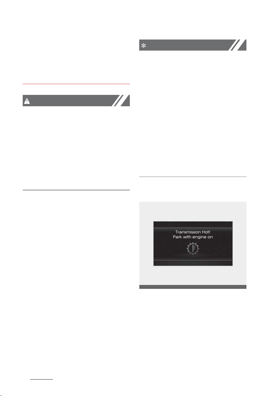
Driving your vehicle
286
All Wheel Drive (AWD) system
re-enter the roadway. In the
event your vehicle leaves the
roadway, do not steer sharply.
Instead, slow down before pulling
back into the travel lanes.
CAUTION
Mud or snow
If one of the front or rear wheels
begins to spin in mud, snow, etc. the
vehicle can sometimes be driven out
by engaging the accelerator pedal
further; however avoid running the
engine continuously at high rpm
because doing so could damage the
AWD system.
Driving in sand or mud
䳜 Maintain slow and constant
speed. Operate the accelerator
pedal slowly to ensure safe driv
-
ing (wheel-slip prevention).
䳜 Keep sufficient distance between
your vehicle and the vehicle in
front of you.
䳜 Reduce vehicle speed and always
check the road condition.
䳜 Avoid speeding, rapid acceleration,
sudden brake applications, and
sharp turns to prevent getting
stuck.
䳜 When the vehicle is stuck in snow,
sand or mud, the tires may not
operate.
䳜 This is to protect the transmis
-
sion and not a malfunction.
NOTICE
Moving the vehicle forcibly to get
out of mud or sand can cause dam
-
age/overheat of the engine or dam
-
age/breakdown of the transmission,
differential or 4WD system as well
as damage to tires. If excessive
wheel slip occurs after entering a
sandy/muddy road, the vehicle may
fall into the sand/mud. When it hap
-
pens, put a stone or a tree branch
under the tire, and then try to pull
out the vehicle, or try to get it
unstuck by repeatedly moving for
-
wards and backwards.
Transmission overheated
OMQ4050023L

29
6
6
Driving your vehicle All Wheel Drive (AWD) system
䳜 When driving on muddy and sandy
roads under the severe condition,
the transmission could be over
-
heated.
䳜 When the transmission is over
-
heated, the safe protection mode
engages and the "Transmission
Hot! Park with engine on" warning
message will appear on the LCD
display with a chime.
䳜 If this occurs, pull over to a safe
location, stop the vehicle with the
engine running, apply the brakes
and shift the vehicle to P (Park),
and allow the transmission to
cool.
䳜 If you ignore this warning, the
driving condition may become
worse. You may experience
abrupt shifts, frequent shifts, or
jerkiness. To return to the normal
driving condition, stop the vehicle
and apply the foot brake or shift
into P (Park). Then allow the
transmission to cool for a few
minutes with engine on, before
driving off.
䳜 When the message "Trans cooled.
Resume driving" appears you can
continue to drive your vehicle.
If the warning messages in the LCD
display continue to blink, for your
safety, have the system checked by
an authorized Kia dealer.
Tire precautions
Always pay attention to tires for
AWD (all-wheel drive) vehicles.
When driving in all-wheel drive, driv
-
ing force is applied to all tires, and
the driving performance of the vehi
-
cle is greatly affected by the degree
of tire wear:
䳜 When replacing tires, be sure to
equip all four tires with the same
size, type, tread, brand and load-
carrying capacity. Do not use tire
and wheel with different size and
type from the one originally
installed on your vehicle. It can
affect the safety and perfor
-
mance of your vehicle, which
could lead to steering failure or
rollover causing serious injury.
䳜 Replace the front and rear tire
positions every 6,000 miles
(10,000 km).
䳜 Each tire should be checked
monthly when cold and inflated to
inflation pressure recommended
by the vehicle manufacturer on
the vehicle placard or tire inflation
pressure label.
OMQ4050032L
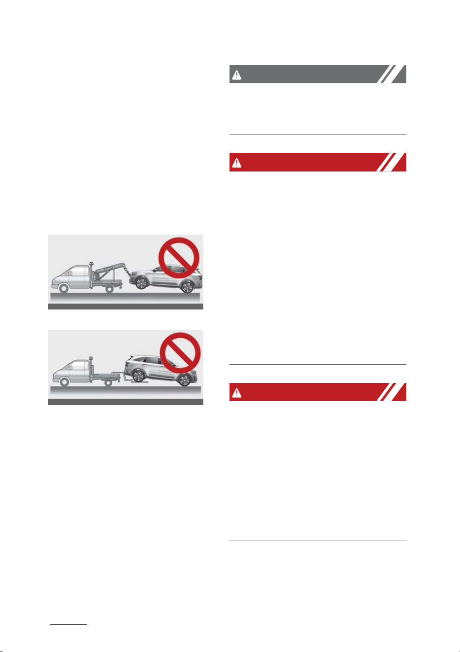
Driving your vehicle
306
All Wheel Drive (AWD) system
䳜 For AWD (all-wheel drive) vehicles,
install the chains on the front
wheels. However, this may dam
-
age the AWD system, so keep the
travel distance as short as possi
-
ble.
* Refer to "Tire chains" on page 6-
221.
Towing precautions
AWD vehicle
FWD vehicle
The AWD vehicle should never be
towed with the wheels on the
ground. Your vehicle must be towed
with a wheel lift and dollies or flat
-
bed equipment with all the wheels
off the ground.
* Refer to "Trailer towing (if
equipped)" on page 6-224.
CAUTION
The AWD vehicle cannot be towed
with sling-type equipment. Use
wheel lift or flatbed equipment.
WARNING
Your vehicle is equipped with tires
designed to provide safe ride and
handling capability. Do not use tires
and wheels that are different in size
and type from the originally
installed ones. It can affect the
safety and performance of your
vehicle, which could lead to steering
failure or rollover and serious injury.
When replacing the tires, be sure to
equip all four tires with the tire and
wheel of the same size, type, tread,
brand and load-carrying capacity.
WARNING
Jacked vehicle
While the full-time AWD vehicle is
being raised on a jack, never start
the engine or cause the tires to
rotate.
There is the danger that rotating
tires touching the ground could
cause the vehicle to go off the jack
and to jump forward.
䳜 Full-time AWD vehicles must be
tested on a special four wheel
chassis dynamometer.
OMQ4H060010
OMQ4H060011
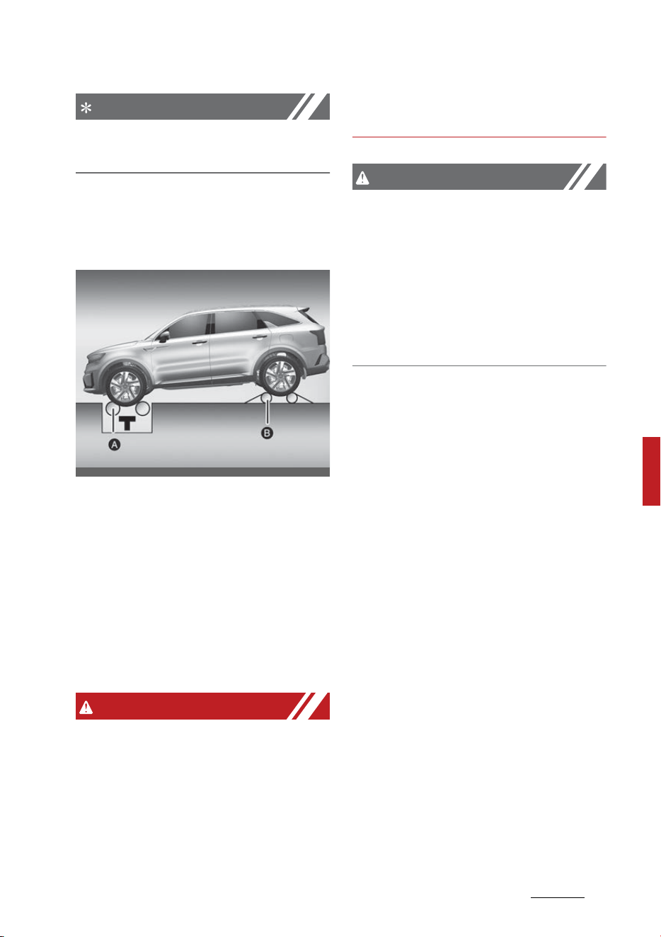
31
6
6
Driving your vehicle All Wheel Drive (AWD) system
NOTICE
Never engage the parking brake
while performing these tests.
䳜 A full-time AWD vehicle should
not be tested on a FWD roll tester.
If a FWD roll tester must be used,
perform the following:
[A]: Roll tester
[B]: Temporary free roller
1. Check the tire pressures recom
-
mended for your vehicle.
2. Place the front wheels on the roll
tester (A) for a speedometer test.
3. Release the parking brake.
4. Place the rear wheels on the tem
-
porary free roller (B).
WARNING
Dynamometer testing
Keep away from the front of the
vehicle while the vehicle is in gear on
the dynamometer. This is very dan
-
gerous as the vehicle can jump for
-
ward and cause serious injury or
death.
CAUTION
䳜 When lifting up the vehicle, do not
operate front and rear wheel sep
-
arately. All four wheels should be
operated.
䳜 If you need to operate the front
wheel and rear wheel when lifting
up the vehicle, you should release
the parking brake.
OMQ4PH051041N

Driving your vehicle
326
Brake system
Brake system
Your vehicle has power-assisted
brakes, parking brake, and various
braking systems for safe driving.
Power brakes
Your vehicle has power-assisted
brakes that adjust automatically
through normal usage.
In the event that the power-
assisted brakes lose power because
of a stalled engine or some other
reason, you can still stop your vehi
-
cle by applying greater force to the
brake pedal than you normally
would. The stopping distance, how
-
ever, will be longer.
When the engine is not running, the
reserve brake power is partially
depleted each time the brake pedal
is applied. Do not pump the brake
pedal when the power assist has
been interrupted.
CAUTION
Brake pedal
Do not drive with your foot resting
on the brake pedal. This will create
abnormally high brake tempera
-
tures which can cause excessive
brake lining and pad wear.
WARNING
Steep hill braking
Avoid continuous application of the
brakes when descending a long or
steep hill by shifting to a lower gear.
Continuous brake application will
cause the brakes to overheat and
could result in a temporary loss of
braking performance.
WARNING
HEV driving down hill
Do not turn off the vehicle while
going down a hill.The brake booster
may not work sufficiently and the
braking distance may be longer.
Wet brakes may impair the vehicle's
ability to safely slow down; the
vehicle may also pull to one side
when the brakes are applied. Apply
-
ing the brakes lightly will indicate
whether they have been affected in
this way. Always test your brakes in
this fashion after driving through
deep water. To dry the brakes, apply
them lightly while maintaining a
safe forward speed until brake per
-
formance returns to normal.
In the event of brake failure
If service brakes fail to operate
while the vehicle is in motion, you
can make an emergency stop with
the parking brake. The stopping dis
-

33
6
6
Driving your vehicle Brake system
tance, however, will be much
greater than normal.
WARNING
Parking brake
Avoid applying the parking brake to
stop the vehicle while it is moving
except in an emergency situation.
Applying the parking brake while the
vehicle is moving at normal speeds
can cause a sudden loss of control
of the vehicle. If you must use the
parking brake to stop the vehicle,
use great caution in applying the
brake.
Brake Over Accelerator
In the event the accelerator pedal
becomes stuck or entrapped, apply
steady and firm pressure to the
brake pedal to slow the vehicle and
reduce engine power.
If you experience this condition, take
the following steps:
1. Apply the brakes and bring your
vehicle to a safe stop.
2. Move the transmission to P
(Park), switch the engine off and
apply the parking brake.
3. Inspect the accelerator pedal for
any interference.
If none are found and the condition
persists, have your vehicle towed to
an authorized Kia dealer.
Disc brakes wear indicator
When your brake pads are worn and
new pads are required, you will hear
a high-pitched warning sound from
your front brakes or rear brakes.
You may hear this sound come and
go or it may occur whenever you
press the brake pedal.
Please remember that some driving
conditions or climates may cause a
brake squeal when you first apply
(or lightly apply) the brakes. This is
normal and does not indicate a
problem with your brakes.
Always replace the front or rear
brake pads as pairs.
CAUTION
Replace brake pads
Do not continue to drive with worn
brake pads. Continuing to drive with
worn brake pads can damage the
braking system and result in costly
brake repairs.
WARNING
Brake wear
Do not ignore high pitched wear
sounds from your brakes. If you
ignore this audible warning, you will
eventually lose braking perfor
-
mance, which could lead to a serious
accident.
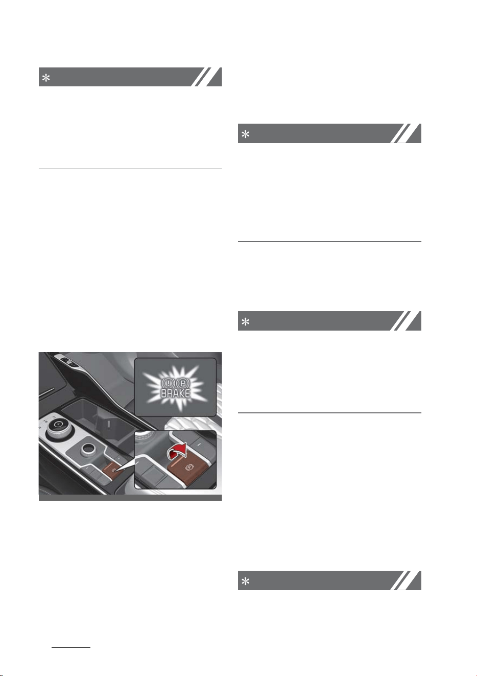
Driving your vehicle
346
Brake system
NOTICE
Brake dust may accumulate on the
wheels, even under normal driving
conditions. Some dust is inevitable
as the brakes wear and contribute
to brake noise.
Electronic Parking Brake (EPB)
After parking the vehicle, apply the
Electronic Parking Brake (EPB) to
prevent the vehicle from being
moved by the external force.
Applying the parking brake
Applying the parking brake manu
-
ally
1. Depress the brake pedal.
2. Pull up the EPB switch.
Make sure the warning light comes
on.
Also, the EPB is applied automati
-
cally if the AUTO HOLD button is on
when the vehicle is turned off. In
addition, if you pull up the EPB
switch after the vehicle is turned
off, the EPB will be applied.
NOTICE
On a steep incline or when pulling a
trailer, if the vehicle does not remain
at a standstill, do as follows:
1. Apply the EPB.
2. Pull up the EPB switch for more
than 3 seconds.
Do not operate the EPB while the
vehicle is moving except in an emer
-
gency situation.
NOTICE
A click or electric brake motor whine
sound may be heard while operating
or releasing the EPB. These condi
-
tions are normal and indicate that
the EPB is functioning properly.
Applying the parking brake auto
-
matically
The EPB is applied automatically
under following conditions.
䳜 The EPB is overheated
䳜 The driver turns the vehicle OFF
while AUTO HOLD is operating
䳜 Requested by other systems
NOTICE
For Electronic Parking Brake (EPB)
equipped vehicles with AUTO HOLD
OMQ4H050025
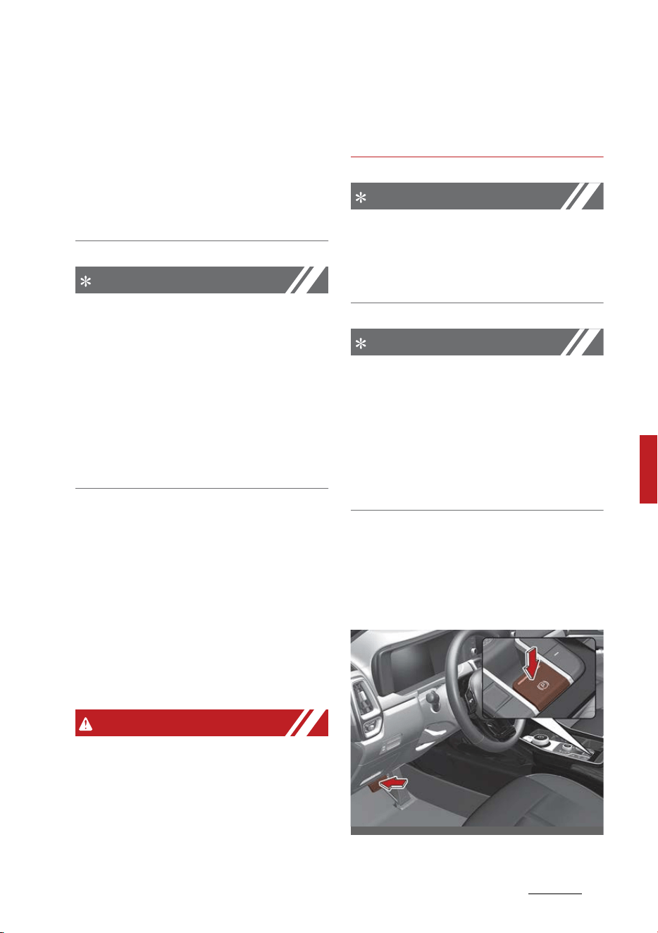
35
6
6
Driving your vehicle Brake system
function used while driving, if the
ENGINE START/STOP button has
been turned OFF, the EPB will be
engaged automatically. Therefore,
AUTO HOLD function should be
turned off before the ENGINE
START/STOP button is turned off.
NOTICE
For Electronic Parking Brake (EPB)
equipped vehicles with AUTO HOLD
function used while driving, if the
ENGINE START/STOP button has
been turned OFF, the EPB will be
engaged automatically. Therefore,
AUTO HOLD function should be
turned off before the ENGINE
START/STOP button is turned off.
Emergency braking
If there is a problem with the brake
pedal while driving, emergency
braking is possible by pulling up and
holding the EPB switch. Braking is
possible only while you are holding
the EPB switch. However, braking
distance will be longer than normal.
WARNING
Do not operate the Electronic Park
-
ing Brake (EPB) while the vehicle is
moving except in an emergency sit
-
uation. Applying the EPB while the
vehicle is moving at normal speeds
can cause a sudden loss of control
of the vehicle. If you must use the
EPB to stop the vehicle, use great
caution in applying the brake.
NOTICE
During emergency braking by the
EPB, the parking brake warning light
will illuminate to indicate that the
system is operating.
NOTICE
If you notice a continuous noise or
burning smell when the EPB is used
for emergency braking, have your
vehicle checked by a professional
workshop. Kia recommends to visit
an authorized Kia dealer/service
partner.
Releasing the parking brake
Releasing the parking brake manu
-
ally
OMQ4AH050026
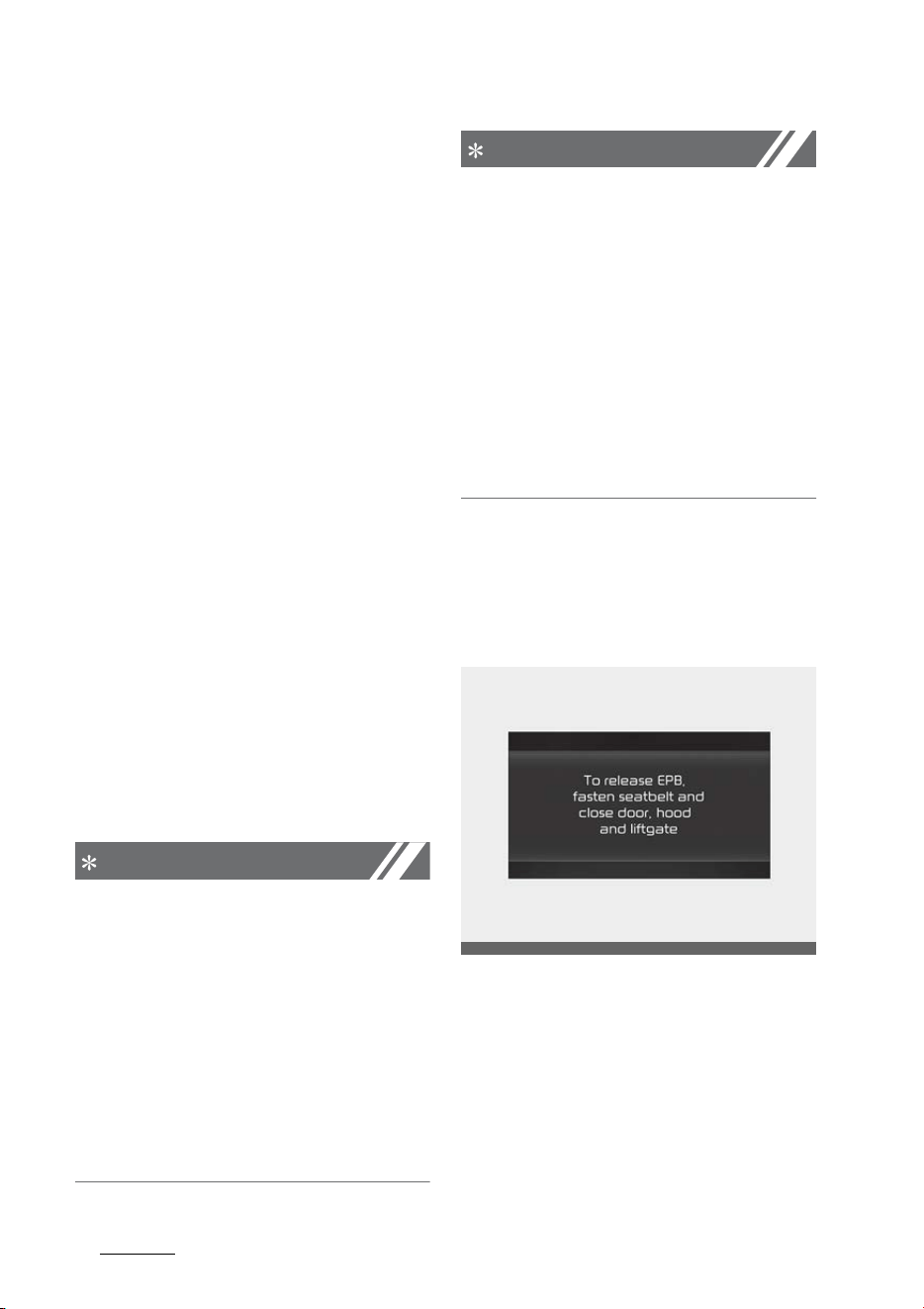
Driving your vehicle
366
Brake system
1. Have the ENGINE START/STOP
button in the ON position.
2. Press the brake pedal.
3. Make sure the gear is shifted to P
(Park) position.
4. Press the EPB switch.
5. Make sure the brake warning light
goes off.
Releasing the parking brake auto
-
matically
䳜 Under following conditions, the
EPB is released automatically
after slowly depressing the accel
-
erator pedal. For your safety,
check if the brake warning light is
turned off.
- The vehicle engine is running
- The driver's seat belt is fas
-
tened
- The driver's door, hood, trunk is
closed
- The gear is in R (Reverse) or D
(Drive)
NOTICE
䳜 For your safety, you can engage
the EPB even though the ENGINE
START/STOP button is in the OFF
position, but you cannot release
it.
䳜 For your safety, depress the
brake pedal and release the park
-
ing brake manually with the EPB
switch when you drive downhill or
when backing up the vehicle.
NOTICE
䳜 If the parking brake warning light
is still on even though the EPB has
been released, have the system
checked by a professional work
-
shop. Kia recommends to visit an
authorized Kia dealer/service
partner.
䳜 Do not drive your vehicle with the
EPB applied. It may cause exces
-
sive brake pad and brake rotor
wear.
EPB warning messages
To release EPB, fasten seatbelt,
close door, hood, and trunk
䳜 If you try to drive off while
engaging the accelerator pedal
with the EPB applied, but the EPB
doesn't release automatically, a
warning will sound and a message
will appear.
䳜 If the driver's seat belt is not fas
-
tened and the vehicle hood,
OMQ4AH050049

37
6
6
Driving your vehicle Brake system
driver's door or trunk is opened, a
warning will sound and a message
will appear.
䳜 If there is a problem with the
vehicle, a warning may sound and
a message may appear.
If the situation occurs, press the
brake pedal and release EPB by
pressing the EPB switch.
WARNING
䳜 Whenever leaving the vehicle or
parking, always come to a com
-
plete stop and continue to
depress the brake pedal.
Shift the gear into P (Park), pull
the EPB switch, and press the
ENGINE START/STOP button to
the OFF position. Take the key
with you when leaving the vehicle.
Vehicles not fully engaged in P
(Park) with the parking brake set
are at risk for moving inadver
-
tently and causing injury to your
-
self or others.
䳜 Never allow a passenger to touch
the parking brake. If the parking
brake is released unintentionally,
serious injury may occur.
䳜 Only release EPB when you are
seated inside the vehicle with
your foot firmly on the brake
pedal.
NOTICE
䳜 Do not apply the accelerator pedal
while the parking brake is
engaged. If you depress the accel
-
erator pedal with EPB engaged, a
warning will sound and a message
will appear. Damage to the park
-
ing brake may occur.
䳜 Driving with the parking brake on
can overheat the braking system
and cause premature wear or
damage to brake parts. Make sure
EPB is released and the Parking
Brake warning light is off before
driving.
NOTICE
䳜 A click or electric brake motor
whine sound may be heard while
operating or releasing the EPB.
These conditions are normal and
indicate that the EPB is function
-
ing properly.
䳜 When leaving your keys with a
parking lot attendant or valet,
make sure to inform him/her how
to operate the EPB.
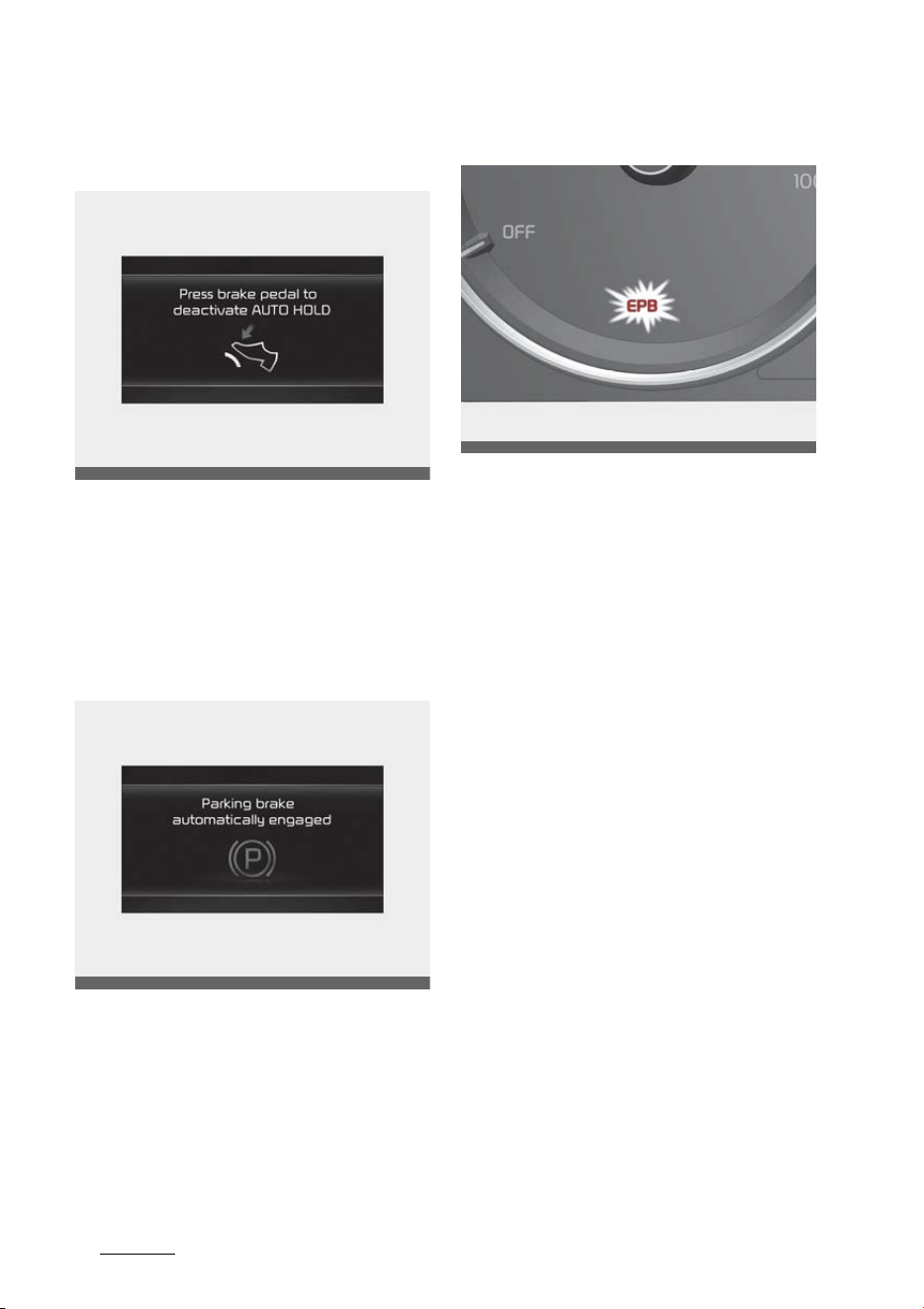
Driving your vehicle
386
Brake system
Press brake pedal to deactivate
AUTO HOLD
When the conversion from AUTO
HOLD to EPB is not working properly
a warning will sound and a message
will appear.
Parking brake automatically
engaged
When EPB is applied while AUTO
HOLD is activated, a warning will
sound and a message will appear.
EPB malfunction
This warning light illuminates if the
ENGINE START/STOP button is
changed to the ON position and goes
off in approximately 3 seconds if
the system is operating normally.
If the EPB malfunction indicator
remains on, comes on while driving,
or does not come on when the
ENGINE START/STOP button is
changed to the ON position, this
indicates that the EPB may have
malfunctioned.
If this occurs, have your vehicle
checked by a professional workshop
as soon as possible. Kia recom
-
mends to visit an authorized Kia
dealer/service partner.
The EPB malfunction indicator may
illuminate when the ESC indicator
comes on to indicate that the ESC is
not working properly, but it does
not indicate a malfunction of the
EPB.
OMQ4050056L
OMQ4050054L
OMQ4AH050050
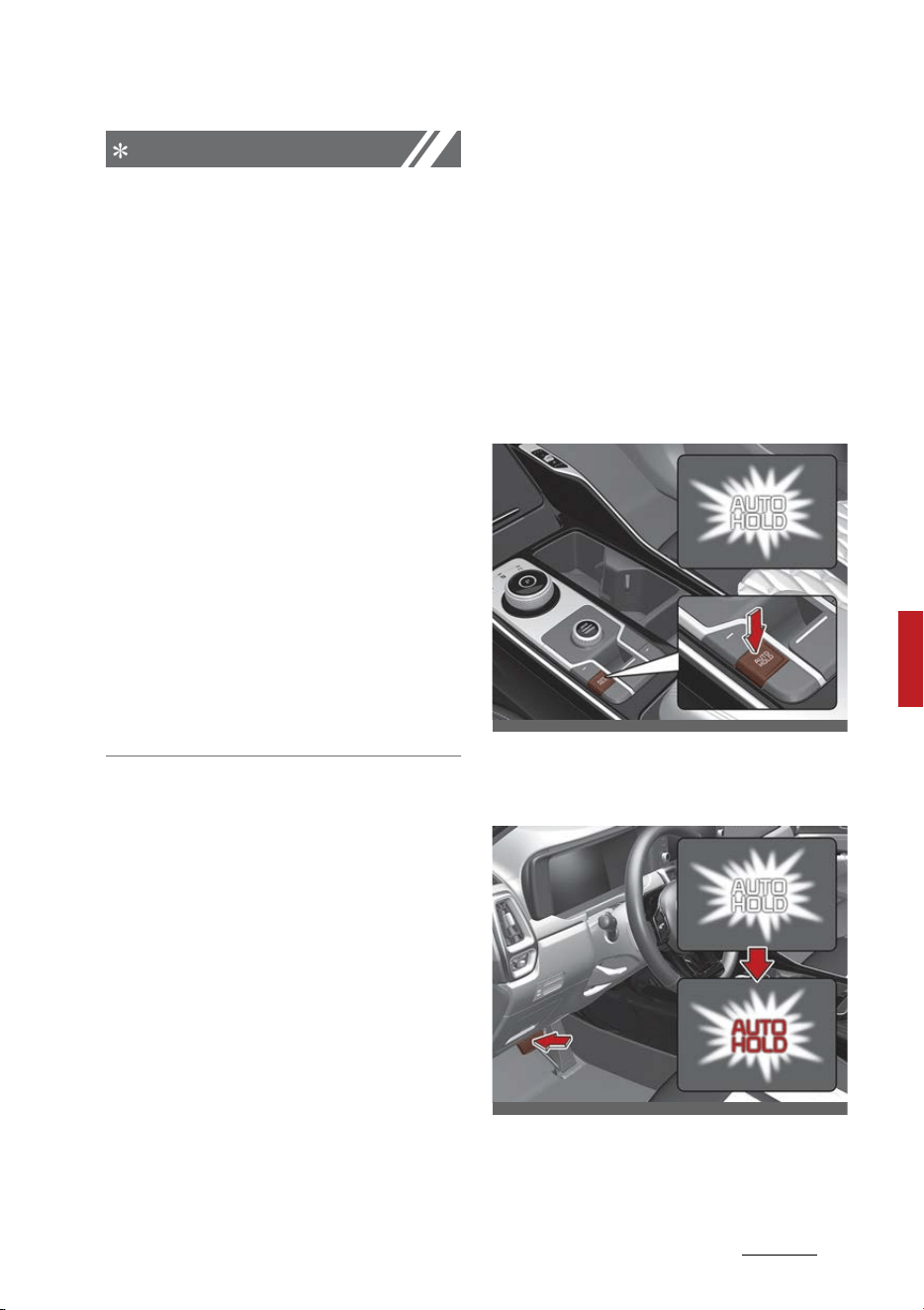
39
6
6
Driving your vehicle Brake system
NOTICE
䳜 If the EPB warning light is still on,
have the system checked by a
professional workshop. Kia rec
-
ommends to visit an authorized
Kia dealer/service partner.
䳜 If the parking brake warning light
does not illuminate or blinks even
though the EPB switch was pulled
up, the EPB is not applied.
䳜 If the parking brake warning light
blinks when the EPB warning light
is on, press the EPB switch, then
pull it up. Once more press it back
to its original position and pull it
back up. If the EPB warning does
not go off, have the system
checked by a professional work
-
shop. Kia recommends to visit an
authorized Kia dealer/service
partner.
When the EPB is not released
If the EPB does not release nor
-
mally, take your vehicle to a profes
-
sional workshop by loading the
vehicle on a flatbed tow truck and
have the system checked. Kia rec
-
ommends to visit an authorized Kia
dealer/service partner.
AUTO HOLD
The Auto Hold is designed to main
-
tain the vehicle in a standstill even
though the brake pedal is not
pressed after the driver brings the
vehicle to a complete stop by press
-
ing the brake pedal.
Applying Auto Hold function
1. Press the brake pedal and start
the vehicle.
2. Press the Auto Hold button. The
white AUTO HOLD indicator will
come on indicating the system is
in standby.
Before the Auto Hold will engage,
the driver's door, liftgate and
engine hood must be closed.
When coming to a complete stop by
pressing the brake pedal, the AUTO
HOLD indicator changes from white
OMQ4H050027
OMQ4050052
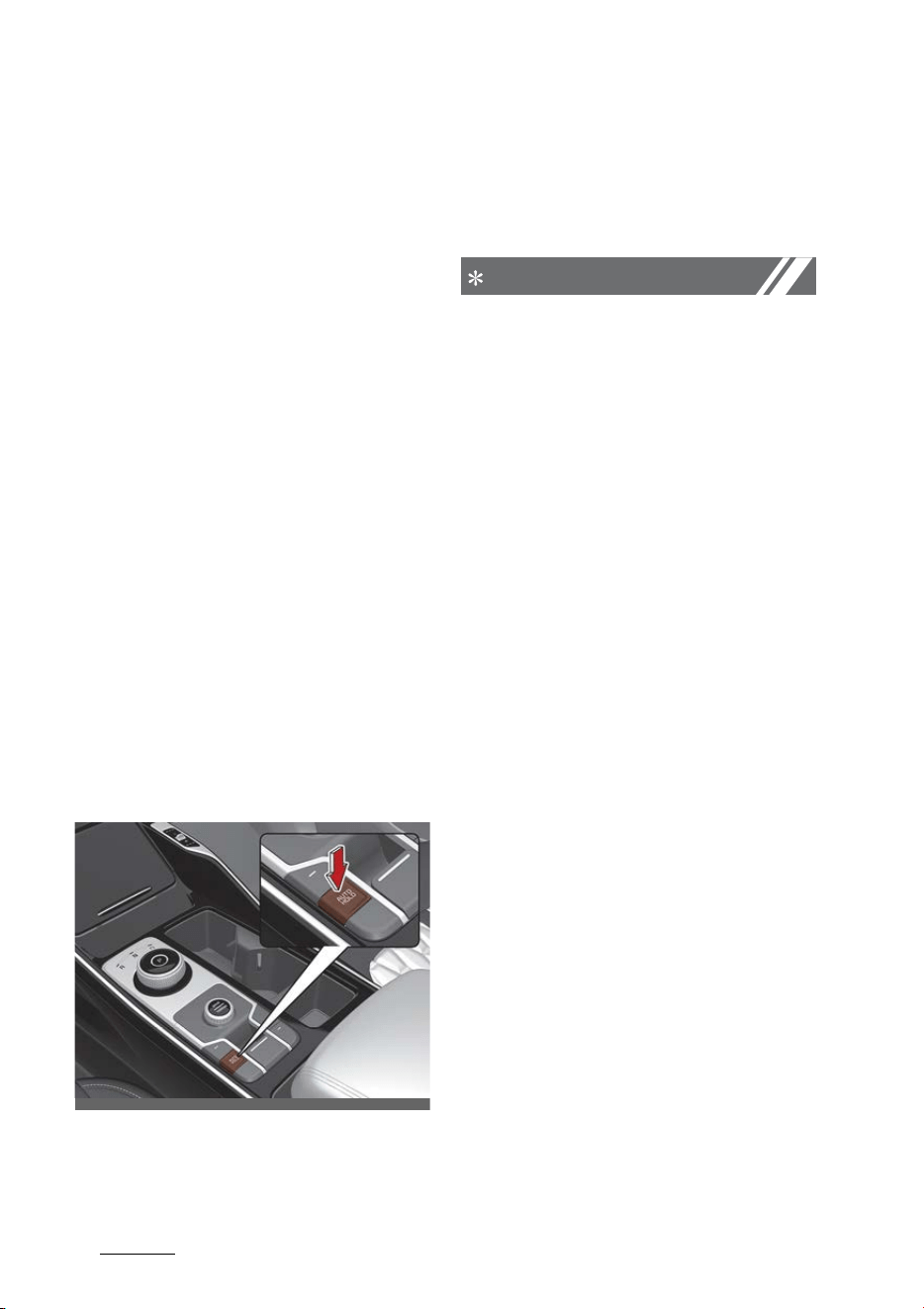
Driving your vehicle
406
Brake system
to green indicating the AUTO HOLD
is engaged. The vehicle will remain
at a standstill even if you release
the brake pedal.
If EPB is applied, Auto Hold will be
released.
If you press the accelerator pedal
with the gear in D (Drive), R
(Reverse) or Manual mode, the Auto
Hold will be released automatically
and the vehicle will start to move.
The indicator changes from green to
white indicating the Auto Hold is in
standby and the EPB is released.
When driving off from Auto Hold by
pressing the accelerator pedal,
always check the surrounding area
near your vehicle.
Slowly press the accelerator pedal
for a smooth launch.
Canceling Auto Hold function
䳜 To cancel the Auto Hold operation,
press the Auto Hold switch. The
AUTO HOLD indicator will go out.
䳜 To cancel the Auto Hold operation
when the vehicle is at a standstill,
press the Auto Hold switch while
pressing the brake pedal.
NOTICE
䳜 The following are conditions when
the Auto Hold will not engage
(Auto Hold light will not turn
green and the Auto Hold system
remains in stand by):
- The driver's door is opened
- The engine hood is opened
- The liftgate is opened
- The gear is in P (Park)
- The EPB is applied
䳜 For your safety, the Auto Hold
automatically switches to EPB
under any of the following condi
-
tions (Auto Hold light remains
white and the EPB automatically
applies):
- The driver's door is opened.
- The engine hood is opened.
- The liftgate is opened
- The vehicle is in a standstill for
more than 10 minutes.
- The vehicle is standing on a
steep slope.
- The vehicle moved for a few
seconds.
In these cases, the brake warn
-
ing light comes on, the AUTO
HOLD indicator changes from
green to white, and a warning
sounds and a message will
appear to inform you that EPB
OMQ4H050028
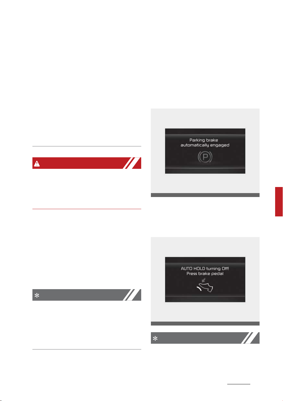
41
6
6
Driving your vehicle Brake system
has been automatically
engaged. Before driving off
again, press foot brake pedal,
check the surrounding area
near your vehicle and release
parking brake manually with
the EPB switch.
䳜 If the AUTO HOLD indicator lights
up yellow, the Auto Hold is not
working properly. Take your vehi
-
cle and have the system checked
by an authorized Kia dealer.
WARNING
To reduce the risk of an accident, do
not activate Auto Hold while driving
downhill, backing up or parking your
vehicle.
If there is a malfunction with the
driver's door, liftgate or engine hood
open detection system, the Auto
Hold may not work properly.
Take your vehicle and have the sys
-
tem checked by an authorized Kia
dealer.
NOTICE
A click or electric brake motor whine
sound may be heard while operating
or releasing the EPB, but these con
-
ditions are normal and indicate that
the EPB is functioning properly.
Warning messages
The Auto Hold function will display a
warning message with sound under
certain conditions.
When the EPB is applied from Auto
Hold, a warning will sound and a
message will appear.
When the conversion from Auto
Hold to EPB is not working properly
a warning will sound and a message
will appear.
NOTICE
When this message is displayed, the
Auto Hold and EPB may not operate.
OMQ4050054L
OMQ4050055L
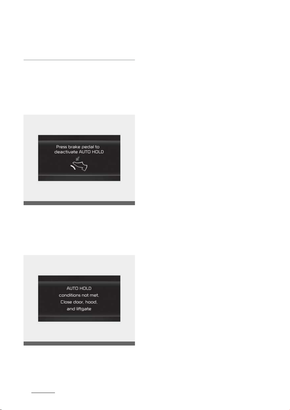
Driving your vehicle
426
Brake system
For your safety, press the brake
pedal.
If you do not apply the brake pedal
when you release the Auto Hold by
pressing the [AUTO HOLD] switch, a
warning will sound and a message
will appear.
When you press the [AUTO HOLD]
switch, if the driver's door, liftgate
and engine hood are not closed, a
warning will sound and a message
will appear on the LCD display.
At this moment, press the [AUTO
HOLD] button after closing the
driver's door and engine hood and
liftgate.
Anti-lock Brake System (ABS)
The Anti-lock Brake System (ABS)
prevents the wheels from locking.
So the vehicle remains stable and
can still be steered.
ABS (or ESC) will not prevent acci
-
dents due to improper or dangerous
driving maneuvers. Even though
vehicle control is improved during
emergency braking, always main
-
tain a safe distance between you
and objects ahead. Vehicle speeds
should always be reduced during
extreme road conditions. The vehicle
should be driven at reduced speeds
in the following circumstances:
䳜 When driving on rough, gravel or
snow-covered roads
䳜 When driving with tire chains
installed.
䳜 When driving on roads where the
road surface is pitted or has dif
-
ferent surface heights.
Driving in these conditions increases
the stopping distance for your vehi
-
cle.
The ABS continuously senses the
speed of the wheels. If the wheels
are going to lock, the ABS repeat
-
edly modulates the hydraulic brake
pressure to the wheels.
OMQ4050056L
OMQ4AH050057
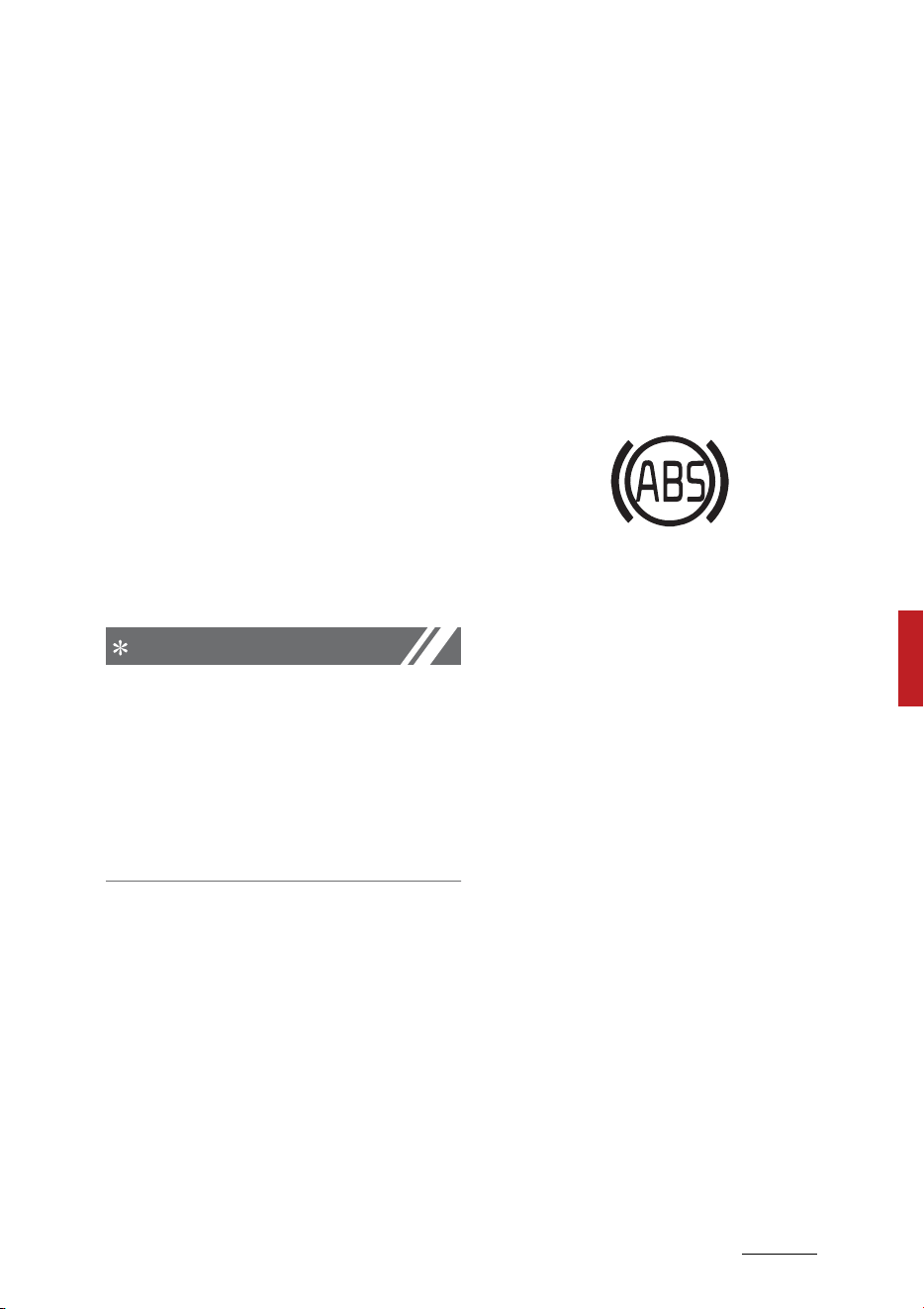
43
6
6
Driving your vehicle Brake system
When you apply your brakes under
conditions which may lock the
wheels, you may hear a "tik-tik''
sound from the brakes, or feel a
corresponding sensation in the
brake pedal. This is normal and it
means your ABS is active.
In order to obtain the maximum
benefit from your ABS in an emer
-
gency situation, do not attempt to
modulate your brake pressure and
do not try to pump your brakes.
Press your brake pedal as hard as
possible to allow the ABS to control
the force being delivered to the
brakes.
NOTICE
A click sound may be heard in the
vehicle compartment when the
vehicle begins to move after the
vehicle is started. These conditions
are normal and indicate that the
Anti-lock Brake System is function
-
ing properly.
Even with the Anti-lock Brake Sys
-
tem, your vehicle still requires suffi
-
cient stopping distance. Always
maintain a safe distance from the
vehicle in front of you.
Always slow down when cornering.
The Anti-lock Brake System cannot
prevent accidents resulting from
excessive speeds.
On loose or uneven road surfaces,
operation of the Anti-lock Brake
System may result in a longer stop
-
ping distance than for vehicles
equipped with a conventional brake
system.
The ABS warning light will stay on
for approximately 3 seconds after
the ENGINE START/STOP button is
ON.
During that time, the ABS will go
through self-diagnosis and the light
will go off if everything is normal. If
the light stays on, you may have a
problem with your ABS. Contact and
visit an authorized Kia dealer.
When you drive on a road having
poor traction, such as an icy road,
and have operated your brakes con
-
tinuously, the ABS will be active
continuously and the ABS warning
light may illuminate. Pull your vehi
-
cle over to a safe place and stop the
vehicle.
Restart the vehicle. If the ABS
warning light goes off, then your
ABS is normal. Otherwise, you may
have a problem with the ABS. Con
-
tact and visit an authorized Kia
dealer.
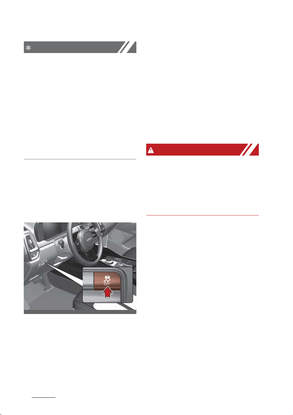
Driving your vehicle
446
Brake system
NOTICE
When you jump start your vehicle
because of a drained battery, the
vehicle may not run as smoothly
and the ABS warning light may turn
on at the same time. This happens
because of low battery voltage. It
does not mean your ABS has mal
-
functioned.
䳜 Do not pump your brakes!
䳜 Have the battery recharged
before driving the vehicle.
Electronic Stability Control (ESC)
system
The Electronic Stability Control
(ESC) is designed to stabilize the
vehicle during cornering maneuvers.
ESC applies the brakes on individual
wheels and intervenes with the
vehicle management system to sta
-
bilize the vehicle.
ESC will not prevent accidents.
Excessive speed in turns, abrupt
maneuvers and hydroplaning on wet
surfaces can still result in serious
accidents.
Only a safe and attentive driver can
prevent accidents by avoiding
maneuvers that cause the vehicle to
lose traction. Even with ESC
installed, always follow all the nor
-
mal precautions for driving - includ
-
ing driving at safe speeds for the
conditions.
WARNING
For maximum protection, always
wear your seat belt. No system, no
matter how advanced, can compen
-
sate for all driver error and/or driv
-
ing conditions. Always drive
responsibly.
The ESC system is an electronic
system designed to help the driver
maintain vehicle control under
adverse conditions. It is not a sub
-
stitute for safe driving practices.
Factors including speed, road condi
-
tions and driver steering input can
all affect whether ESC will be effec
-
tive in preventing a loss of control. It
is still your responsibility to drive
and corner at reasonable speeds
and to leave a sufficient margin of
safety.
When you apply your brakes under
conditions which may lock the
wheels, you may hear a "tik-tik''
sound from the brakes, or feel a
OMQ4051058
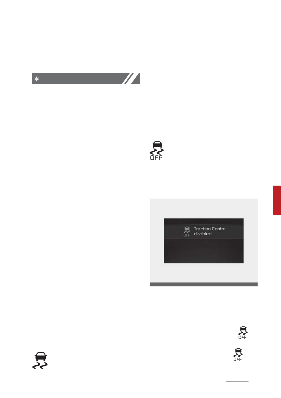
45
6
6
Driving your vehicle Brake system
corresponding sensation in the
brake pedal. This is normal and it
means your ESC is active.
NOTICE
A click sound may be heard in the
vehicle compartment when the
vehicle begins to move after the
vehicle is started. These conditions
are normal and indicate that the
Electronic Stability Control system is
functioning properly.
ESC operation
ESC ON condition
䳜 When the ENGINE START/STOP
button is turned ON, ESC and ESC
OFF indicator lights illuminate for
approximately 3 seconds, then
ESC is turned on.
䳜 Press the ESC OFF button for at
least half a second after turning
the vehicle ON to turn ESC off.
(ESC OFF indicator will illuminate).
To turn the ESC on, press the ESC
OFF button (ESC OFF indicator
light will go off).
䳜 When starting the vehicle, you
may hear a slight ticking sound.
This is the ESC performing an
automatic system self-check and
does not indicate a problem.
When operating
When the ESC is in operation,
the ESC indicator light blinks.
When the Electronic Stability Control
is operating properly, you can feel a
slight pulsation in the vehicle. This is
only the effect of brake control and
indicates nothing unusual.
When moving out of the mud or
driving on a slippery road, pressing
the accelerator pedal may not cause
the vehicle rpm (revolutions per
minute) to increase.
ESC operation off
This vehicle has 2 kinds of ESC
off states.
If the vehicle stops when ESC
is off, ESC remains off. Upon
restarting the vehicle, the ESC will
automatically turn on again.
ESC off state 1
To turn off the traction control
function and only operate the brake
control function of the ESC, press
the ESC OFF button (ESC OFF )
for less than 3 seconds and the ESC
OFF indicator light (ESC OFF ) will
illuminate.
OMQ4050059L
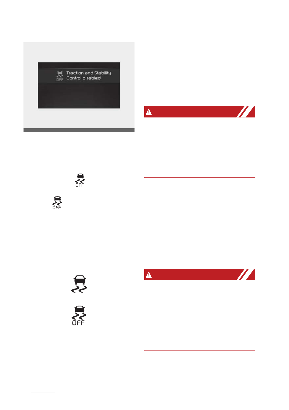
Driving your vehicle
466
Brake system
ESC off state 2
To turn off the traction control
function and the brake control func
-
tion of the ESC, press the ESC OFF
button (ESC OFF ) for more than
3 seconds. ESC OFF indicator light
(ESC OFF ) will illuminate and ESC
OFF warning chime will sound. At
this state, the vehicle stability con
-
trol function does not operate any
more.
Indicator light
ESC indicator light
ESC OFF indicator light
When ENGINE START/STOP button
is turned to ON, the indicator light
illuminates, then goes off if the ESC
system is operating normally.
The ESC indicator light blinks when
-
ever ESC is operating or illuminates
when ESC fails to operate.
The ESC OFF indicator light comes
on when the ESC is turned off with
the button.
WARNING
Electronic Stability Control
Drive carefully even though your
vehicle has Electronic Stability Con
-
trol. It can only assist you in main
-
taining control under certain
circumstances.
ESC OFF usage
When driving
䳜 ESC should be turned on for daily
driving whenever possible.
䳜 To turn ESC off while driving,
press the ESC OFF button while
driving on a flat road surface.
WARNING
Operating ESC
Never press the ESC OFF button
while ESC is operating (ESC indicator
light blinks).
If ESC is turned off while ESC is
operating, the vehicle may slip out
of control.
OMQ4050060L
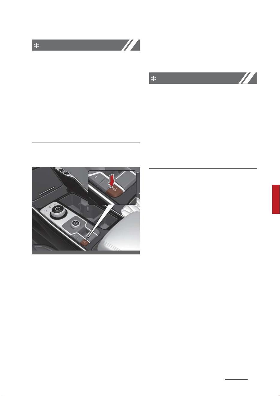
47
6
6
Driving your vehicle Brake system
NOTICE
䳜 When operating the vehicle on a
dynamometer, ensure that the
ESC is turned off (ESC OFF light
illuminated). If the ESC is left on, it
may prevent the vehicle speed
from increasing, and result in
false diagnosis.
䳜 Turning the ESC off does not
affect ABS or brake system oper
-
ation.
Downhill Brake Control (DBC)
The Downhill Brake Control (DBC)
feature assists the driver to
descend down a steep hill without
having to depress the brake pedal.
The system automatically applies
the brakes to maintain the vehicle
speed 2.5 mph (4 km/h) ~ 25 mph
(40 km/h) and allows the driver to
concentrate on steering the vehicle
down hill.
Always turn off the DBC on normal
roads. The DBC might activate inad
-
vertently from the stand by mode
when driving through speed bumps
or making sharp curves.
NOTICE
The DBC defaults to the OFF posi
-
tion whenever the ENGINE START/
STOP button is placed in the ON
position.
Noise or vibration may occur from
the brakes when the DBC is acti
-
vated.
The rear stop light comes on when
DBC is activated.
OMQ4H050029
Driving your vehicle
486
Brake system
DBC operation
Mode Indicator light Description
Standby
illuminated
Press the DBC button when vehicle speed is under 38
mph (60 km/h). The DBC system will turn ON and
enter the standby mode.
The system does not turn ON if vehicle speed is over
38 mph (60 km/h).
Activated
blinks
In the standby mode, It enters the operating mode
when the following conditions are met.
䳜 The road surface should be more than a certain
angle of inclination
䳜 The accelerator pedal must not be depressed.
䳜 The vehicle speed should be within 0mph (0km/h) ~
25mph (40km/h)
Within operating vehicle speed 2.5 mph (4 km/h) ~ 25
mph (40 km/h), the driver can lower or raise the vehi
-
cle speed by stepping on the brake pedal or accelera
-
tor pedal.
Temporarily
deactivated
illuminated
In the activated mode, the DBC will temporarily deac
-
tivate under the following conditions:
䳜 The hill is not steep enough.
䳜 The accelerator pedal is depressed.
䳜 When the vehicle speed is in the range of 25 mph
(40 km/h) ~ 38 mph (60 km/h)
If the above conditions are not met, the DBC will auto
-
matically activate again.
OFF
not illuminated
The DBC will turn OFF under the following conditions:
䳜 The DBC button is pressed again.
䳜 When the accelerator pedal is depressed and the
vehicle speed exceeds 38 mph (60 km/h)

49
6
6
Driving your vehicle Brake system
NOTICE
If the DBC yellow indicator light illu
-
minates, the system may have
overheated or have malfunctioned.
When the warning light illuminates
even though the DBC system has
cooled off, have your vehicle
checked by an authorized Kia dealer
as soon as possible.
NOTICE
䳜 The DBC may not deactivate on
steep inclines even though the
brake or accelerator pedal is
depressed.
䳜 The DBC does not operate when:
- The gear is in P (Park).
- The ESC is activated.
Hill-start Assist Control (HAC)
A vehicle has the tendency to roll
back on a steep hill when it starts to
go after stopping. The Hill-start
Assist Control (HAC) prevents the
vehicle from rolling back by applying
the brakes automatically for about
2 seconds.
The brakes are released when the
accelerator pedal is engaged or
after about 2 seconds.
The HAC is activated only for about
2 seconds, so when the vehicle is
starting off always engaged the
accelerator pedal.
WARNING
Maintaining brake pressure on
incline
HAC does not replace the need to
apply brakes while stopped on an
incline. While stopped, make sure
you maintain brake pressure suffi
-
cient to prevent your vehicle from
rolling backward and causing an
accident. Don't release the brake
pedal until you are ready to acceler
-
ate forward.
Vehicle Stability Management
(VSM) system
The Vehicle Stability Management
(VSM) provides further enhance
-
ments to vehicle stability and steer
-
ing responses under the following
condition:
䳜 when driving on a slippery road or
䳜 when a change in the coefficient
of friction between left and right
wheels is detected.
WARNING
Tire/wheel size
When replacing tires and wheels,
make sure they are the same size
as the original tires and wheels
installed. Driving with varying tire or
wheel sizes may diminish any sup
-
plemental safety benefits of the
VSM system.

Driving your vehicle
506
Brake system
VSM operation
When the VSM is operating properly,
you can feel a slight pulsation in the
vehicle and/or abnormal steering
responses (Electric Power Steering
(EPS)). This is only the effect of
brake and EPS control and indicates
nothing unusual.
The VSM does not operate when:
䳜 Driving on a sloping road such as a
gradient or incline
䳜 Driving in reverse
䳜 ESC OFF indicator light ( )
remains on the instrument cluster
䳜 EPS indicator light remains on the
instrument cluster
VSM operation off
If you press the ESC OFF button to
turn off the ESC, the VSM will also
cancel and the ESC OFF indicator
light ( ) illuminates.
To turn on the VSM, press the but
-
ton again. The ESC OFF indicator
light goes out.
WARNING
Vehicle Stability Management
Drive carefully even though your
vehicle has Vehicle Stability Man
-
agement. It can only assist you in
maintaining control of the vehicle
under certain circumstances.
Malfunction indicator
The VSM can be deactivated even if
you don't cancel the VSM operation
by pressing the ESC OFF button. It
indicates that a malfunction has
been detected somewhere in the
Electric Power Steering system or
VSM system. If the ESC indicator
light ( ) or EPS warning light
remains on, take your vehicle and
have the system checked by an
authorized Kia dealer.
The VSM is not a substitute for safe
driving practices but a supplemen
-
tary function only. It is the respon
-
sibility of the driver to always check
the speed and the distance to the
vehicle ahead. Always hold the
steering wheel firmly while driving.
Your vehicle is designed to activate
according to the driver's intention,
even with installed VSM. Always fol
-
low all the normal precautions for
driving at safe speeds for the condi
-
tions 䳍 including driving in clement
weather and on a slippery road.
WARNING
For maximum protection, always
wear your seat belt. No system, no
matter how advanced, can compen
-
sate for all driver error and/or driv
-
ing conditions. Always drive
responsibly.

51
6
6
Driving your vehicle Brake system
Trailer Stability Assist (TSA) sys
-
tem
The Trailer Stability Assist (TSA) is
operated as a vehicle stability con
-
trol system. The TSA is designed to
stabilize the vehicle and trailer when
the trailer sways or oscillates. There
are various factors that make the
vehicle sway or oscillate.
Such incidents mostly happen at
high speed, but, there is also a risk
of swaying when the trailer is
affected by crosswinds, buffeting or
improper overloading.
Factors of swaying such as:
䳜 High speed
䳜 Strong crosswinds
䳜 Improper overloading
䳜 Sudden controlling of steering
wheel
䳜 Uneven road
The TSA continuously analyzes the
vehicle and trailer instability. When
the TSA detects some sway, the
brakes are applied automatically to
stabilize the vehicle. When the vehi
-
cle becomes stable, the TSA does
not operate.
Brake Assist System (BAS)
The BAS system is to reduce or to
avoid accident risk. It recognizes the
distance from the vehicle ahead or
the pedestrian through the sensors
(i.e. radar and camera), and, if nec
-
essary, warns the driver of accident
risk with the warning message or
the warning alarms.
WARNING
Brake Assist System (BAS) limita
-
tions
The BAS system is a supplemental
system and is not a substitute for
safe driving practices. It is the
responsibility of the driver to always
check the speed and distance to the
vehicle ahead to ensure it is safe to
use.
NOTICE
Take the following precautions
when using the Brake Assist System
(BAS):
This system is only a supplemental
system and it is not intended to, nor
does it replace the need for extreme
care and attention of the driver. The
sensing range and objects detect
-
able by the sensors are limited. Pay
attention to the road conditions at
all times.
NEVER drive too fast in accordance
with the road conditions or while
cornering.
Always drive cautiously to prevent
unexpected and sudden situations
from occurring. BAS does not stop
the vehicle completely and does not
avoid collisions.

Driving your vehicle
526
Brake system
Good braking practices
Good braking practices help keep
occupants safe and extend brake
life.
䳜 Check to be sure the parking
brake is not engaged and the
parking brake indicator light is out
before driving away.
䳜 Driving through water may get
the brakes wet. They can also get
wet when the vehicle is washed.
Wet brakes can be dangerous!
Your vehicle will not stop as
quickly if the brakes are wet. Wet
brakes may cause the vehicle to
pull to one side.
To dry the brakes, apply the
brakes lightly until the braking
action returns to normal, taking
care to keep the vehicle under
control at all times. If the braking
action does not return to normal,
stop as soon as it is safe to do so
and visit an authorized Kia dealer.
䳜 Don't coast down hills with the
vehicle out of gear. This is
extremely hazardous. Keep the
vehicle in gear at all times, use the
brakes to slow down, then shift to
a lower gear so that vehicle brak
-
ing will help you maintain a safe
speed.
䳜 Don't "ride" the brake pedal. Rest
-
ing your foot on the brake pedal
while driving can be dangerous
because the brakes might over
-
heat and lose their effectiveness.
It also increases the wear of the
brake components.
䳜 If a tire goes flat while you are
driving, apply the brakes gently
and keep the vehicle pointed
straight ahead while you slow
down. When you are moving
slowly enough for it to be safe to
do so, pull off the road and stop in
a safe place.
䳜 Be cautious when parking on a hill.
Firmly engage the parking brake
and place the shift dial SBW in P. If
your vehicle is facing downhill,
turn the front wheels into the
curb to help keep the vehicle from
rolling.
If your vehicle is facing uphill, turn
the front wheels away from the
curb to help keep the vehicle from
rolling. If there is no curb or if it is
required by other conditions to
keep the vehicle from rolling,
block the wheels.
䳜 Under some conditions your park
-
ing brake can freeze in the
engaged position. This is most
likely to happen when there is an
accumulation of snow or ice
around or near the rear brakes or
if the brakes are wet. If there is a
risk that the parking brake may
freeze, apply it only temporarily
while you put the shift dial SBW in
P (Parking) and block the rear
wheels so the vehicle cannot roll.
Then release the parking brake.
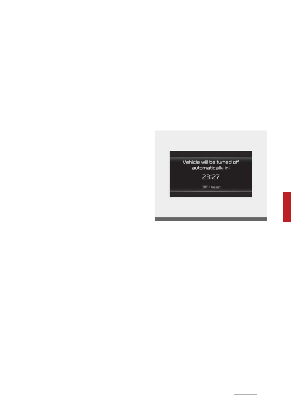
53
6
6
Driving your vehicle Vehicle Auto Shut-off system
䳜 Do not hold the vehicle on an
incline with the accelerator pedal.
This can cause the transmission
to overheat. Always use the brake
pedal or parking brake.
Vehicle Auto Shut-off system (if
equipped)
The vehicle auto shut-off system is
designed to automatically shut off
the vehicle after a certain time the
driver sets to reduce fuel consump
-
tion and energy consumption of the
vehicle and to prevent carbon mon
-
oxide (CO) poisoning.
Prerequisite for activation
This system can be activated, when
the following all prerequisites are
satisfied.
䳜 The ENGINE START/STOP button
is in ON position.
䳜 The vehicle is in P (Park) position.
䳜 The vehicle stops.
䳜 The vehicle speed is under 2 mph
(3 km/h).
䳜 The driver's seat belt is unfas
-
tened.
䳜 The door is opened.
䳜 The passenger's seat is not occu
-
pied.
OMQ4A050356

Driving your vehicle
546
Vehicle Auto Shut-off system
Setting Shut-off Time
The driver can set the shut-off time
on the cluster LCD display.
The option can be found under the
following menu:
䳜 Go to 'User Settings → Conve
-
nience → Vehicle Auto-Shut Off →
60 min./30 min./Disable' to select
the vehicle's shut-off time.
NOTICE
䳜 The default setting will be
retained until the timer is reset.
䳜 The timer will revert back to the
previous setting at the next
startup if the driver selects 'Dis
-
able' in the User Settings mode.
NOTICE
䳜 The default setting is 30 minutes.
Resetting the time
The system can be initialized and
restarted under the following condi
-
tions:
䳜 When pressing and releasing the
brake pedal.
䳜 When the accelerator pedal is
depressed.
䳜 When the driver manually resets
the timer.
䳜 When the driver manually press
the OK button on the steering
wheel.
Canceling the Vehicle Auto Shut-off
system
The system will be canceled auto
-
matically when:
䳜 The vehicle speed is over 2 mph (3
km/h).
䳜 The vehicle is shifted to D (Drive),
R (Reverse) or N (Neutral).
䳜 The driver's seat belt is fastened.
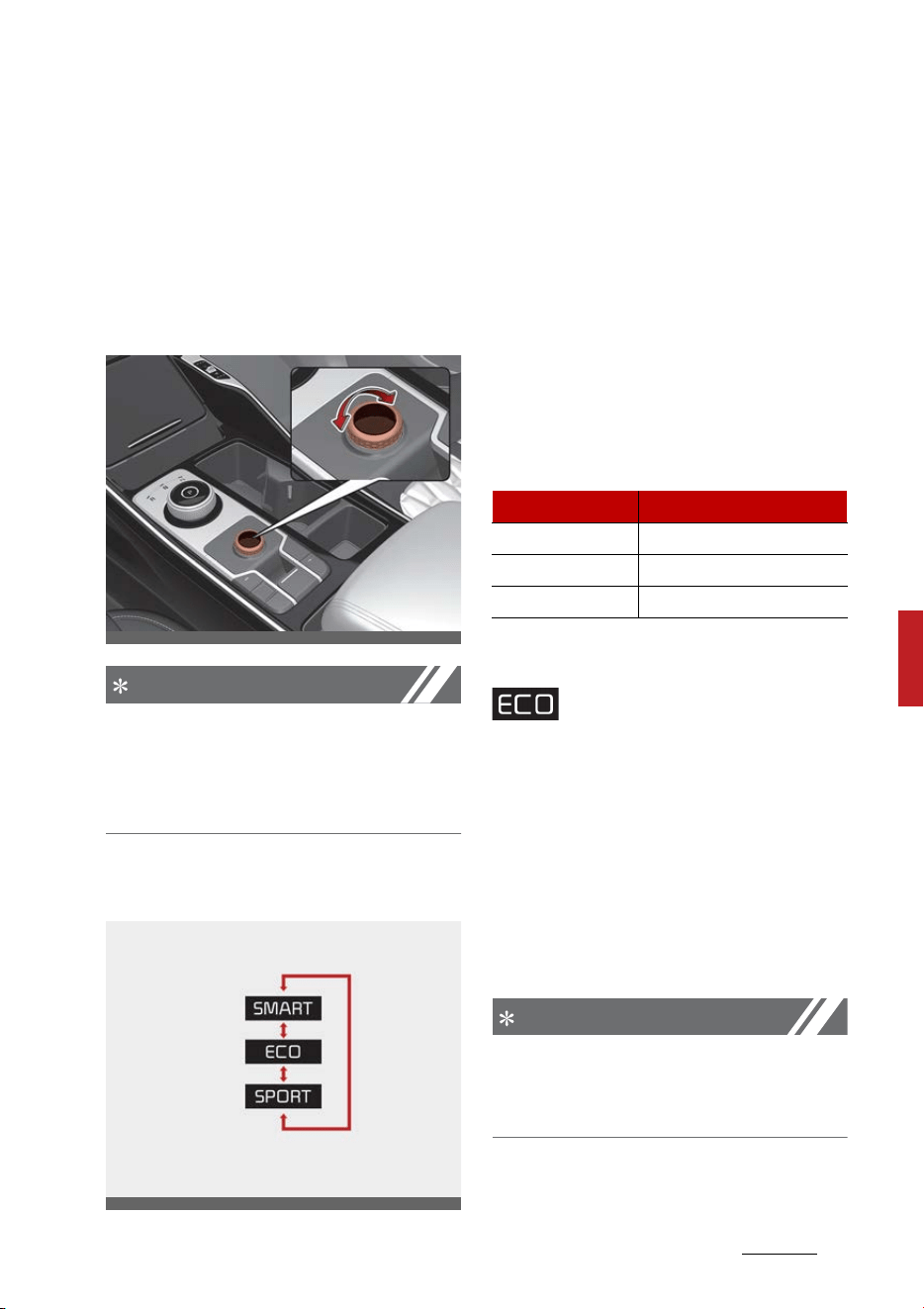
55
6
6
Driving your vehicle Drive mode integrated control system
Drive mode integrated control
system
Drive mode
The drive mode may be selected
according to the driver's preference
or road condition.
NOTICE
If there is a problem with the instru
-
ment cluster, the drive mode will be
in ECO mode and may not change to
SMART mode or SPORT mode.
The mode changes when you toggle
the DRIVE MODE button.
䳜 ECO mode :
ECO mode helps improve fuel effi
-
ciency for eco-friendly driving.
䳜 SPORT mode :
SPORT mode provides sporty but
firm riding.
The drive mode will change to ECO
mode when the engine is restarted.
When changing the drive mode set
-
ting, the responsiveness of Smart
Cruise Control changes. (If equipped)
ECO mode
When the Drive Mode is set
to ECO mode, the engine
and transmission control logic are
changed to maximize fuel efficiency.
䳜 When the ECO mode is selected
by using the DRIVE MODE button,
the ECO indicator will illuminate.
䳜 Whenever the engine is restarted,
the drive mode remains in ECO
mode.
NOTICE
Fuel efficiency depends on the
driver's driving habit and road condi
-
tion.
OMQ4AH050030
OMQ4050319L
Drive Mode SCC Responsiveness
ECO Slow
SPORT Fast
SMART Normal

Driving your vehicle
566
Drive mode integrated control system
When ECO mode is activated:
䳜 The acceleration response may be
slightly reduced as the accelera
-
tor pedal is depressed moder
-
ately.
䳜 The air conditioner performance
may be limited.
䳜 The shift pattern of the auto
-
matic transmission may change.
䳜 The engine noise may get louder.
The above situations are normal
conditions when ECO mode is acti
-
vated to improve fuel efficiency.
Limitation of ECO mode operation:
If the following conditions occur
while ECO mode is operating, the
system operation is limited even
though there is no change in ECO
indicator.
䳜 When the coolant temperature is
low:
The system will be limited until
engine performance becomes
normal.
䳜 When driving up a hill:
The system will be limited to gain
power when driving uphill because
engine torque is restricted.
䳜 When the accelerator pedal is
deeply depressed for a few sec
-
onds:
The system will be limited, judg
-
ing that the driver wants to speed
up.
SPORT mode
SPORT mode manages
the driving dynamics by
automatically adjusting the steer
-
ing effort, the engine and transmis
-
sion control logic for enhanced
driver performance.
䳜 When SPORT mode is selected by
using the DRIVE MODE button, the
SPORT indicator will illuminate.
䳜 Whenever the engine is restarted,
the Drive Mode will revert back to
ECO mode. If SPORT mode is
desired, re-select SPORT mode
from the DRIVE MODE button.
䳜 When SPORT mode is activated:
- The engine rpm will tend to
remain raised over a certain
length of time even after
releasing the accelerator
- Upshifts are delayed when
accelerating
NOTICE
In SPORT mode, the fuel efficiency
may decrease.
SMART mode
SMART mode selects
the proper driving mode
among ECO and SPORT by judging
the driver's driving habits (i.e. Eco
-
nomic or Aggressive (Sportive))
from the brake pedal depression or
the steering wheel operation.

57
6
6
Driving your vehicle Drive mode integrated control system
䳜 Toggle the DRIVE MODE button to
select SMART mode. When
SMART mode is selected, the indi
-
cator illuminates on the instru
-
ment cluster.
䳜 SMART mode automatically con
-
trols the vehicle driving, such as
gear shifting patterns and engine
torque, in accordance with the
driver's driving habits.
NOTICE
䳜 When you mildly drive the vehicle
in SMART mode, the driving mode
changes to ECO mode to improve
fuel efficiency. However, the
actual fuel efficiency may differ in
accordance with your driving situ
-
ations (i.e. upward/downward
slope, vehicle deceleration/accel
-
eration).
䳜 When you dynamically drive the
vehicle in SMART mode by
abruptly decelerating or sharply
turning the driving mode changes
to SPORT mode. However, it may
adversely affect fuel economy.
Various driving situations, which
you may encounter in SMART mode
䳜 The driving mode automatically
changes to ECO mode after a cer
-
tain period of time, when you
gently depress the accelerator
pedal. (Your driving is categorized
to be economic.)
䳜 The driving mode automatically
changes to SMART ECO mode
after a certain period of time,
when you sharply or repetitively
depress the accelerator pedal.
䳜 The driving mode automatically
changes to SMART ECO mode
with the same driving patterns,
when the vehicle starts to drive
on an upward slope of a certain
angle. The driving mode automat
-
ically returns to SMART ECO
mode, when the vehicle enters a
leveled road.
䳜 The driving mode automatically
changes to SMART SPORT, when
you abruptly accelerate the vehi
-
cle or repetitively operate the
steering wheel. (Your driving is
categorized to be sporty.) In this
mode, your vehicle drives in a
lower gear for abrupt accelerat
-
ing/decelerating and increases the
engine brake performance.
䳜 You may still sense the engine
braking performance, even when
you release the accelerator pedal
in SMART SPORT mode. It is
because your vehicle remains in
lower gear over a certain period
of time for next acceleration.
Thus, it is a normal driving situa
-
tion, not indicating any malfunc
-
tion.
䳜 The driving mode automatically
changes to SMART SPORT mode
only in harsh driving situations. In
most of the normal driving situa
-

Driving your vehicle
586
Drive mode integrated control system
tions, the driving mode sets to be
in SMART ECO mode.
Active Snow Mode (ASM)
When the vehicle recognizes fre
-
quent wheel slips on low friction
roads, Active Snow Mode improves
driving stability by minimizing these
wheel slips.
Operating conditions
ASM is activated when all of the fol
-
lowing conditions are met:
䳜 Low outside ambient tempera
-
ture
䳜 Frequent Electronic Stability Con
-
trol (ESC) activation due to wheel
slip
When operating
The vehicle's acceleration response
is reduced, which is similar to
depressing the accelerator pedal
slowly.
Non-operating conditions
ASM is deactivated when one of the
following conditions or more are
met:
䳜 Increase of outside ambient tem
-
perature
䳜 The accelerator pedal is hardly
depressed
䳜 Driving in high speed (e.g. high
-
way driving)
Limitation of SMART mode
The SMART mode may be limited in
following situations. (The OFF indi
-
cator illuminates in those situa
-
tions.)
䳜 Cruise Control or Smart Cruise
Control is activated:
Cruise Control or Smart Cruise
Control may deactivate the
SMART mode when the vehicle is
controlled by the set speed of
Cruise Control or Smart Cruise
Control. (SMART mode is not
deactivated just by activating
Cruise Control or Smart Cruise
Control.)
䳜 The transmission oil temperature
is either extremely low or
extremely high:
The SMART mode can be active in
most of the normal driving situa
-
tions. However, an extremely
high/low transmission oil tem
-
perature may temporarily deacti
-
vate the SMART mode, because
the transmission condition is out
of normal operation condition.
Smart shift on trip computer (if
equipped)
Select the Trip Computer mode on
the instrument cluster LCD display
and move to the smart shift screen.
Then, the driver can see the drive
mode selected and the drive mode
which is automatically switched by
the SMART mode.
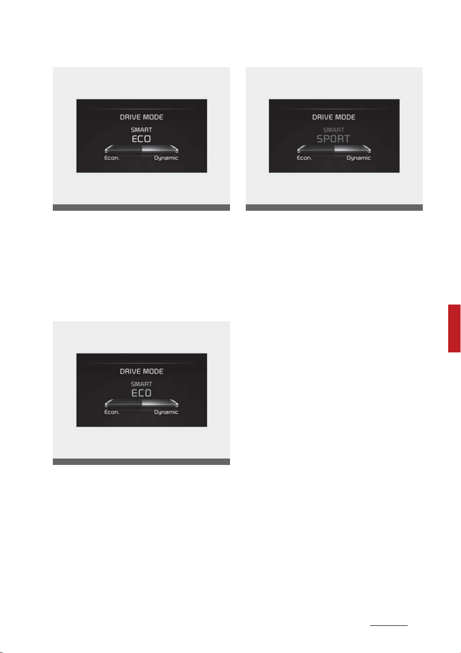
59
6
6
Driving your vehicle Drive mode integrated control system
The drive mode selected by the
driver and the driving style gauge
showing the driver's driving style
are displayed on the screen.
Driver's style gauge in SMART
mode
With the standard driving style in
the center, the left side of the
gauge is 'Econ.' and right side is
'Dynamic' style.
When the left side of the driver's
style gauge is filled up and after a
certain time passes, the SMART ECO
mode is activated automatically.
When the right side of the gauge is
filled up and sporty driving condition
is detected, the SMART SPORT
mode is activated.
To maintain the SMART ECO mode
for fuel efficiency, drive with the
left side of the gauge filled up.
OMQ4AH050330
OMQ4050285L
OMQ4050286L
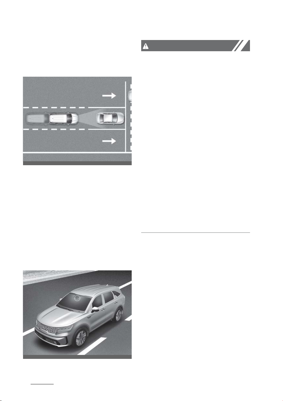
Driving your vehicle
606
Forward Collision-Avoidance Assist (FCA) (Front
view camera only)
Forward Collision-Avoidance
Assist (FCA) (Front view camera
only) (if equipped)
Forward Collision-Avoidance Assist
is designed to help detect and moni
-
tor the vehicle ahead or help detect
a pedestrian in the roadway and
warn the driver that a collision is
imminent with a warning message
and an audible warning, and if nec
-
essary, apply emergency braking.
Detecting sensor
Front view camera
CAUTION
Take the following precautions to
maintain optimal performance of
the detecting sensor:
䳜 Never disassemble the detecting
sensor or sensor assembly, or
apply any impact on it.
䳜 Never install any accessories or
stickers on the front windshield,
or tint the front windshield.
䳜 If the detecting sensors have
been replaced or repaired, have
the vehicle be inspected by an
authorized Kia dealer.
䳜 Pay extreme caution to keep the
front view camera dry.
䳜 Never place any reflective objects
(i.e. white paper, mirror) over the
dashboard. Any light reflection
may prevent the function from
functioning properly.
OMQ4AH050240
OMQ4H051009
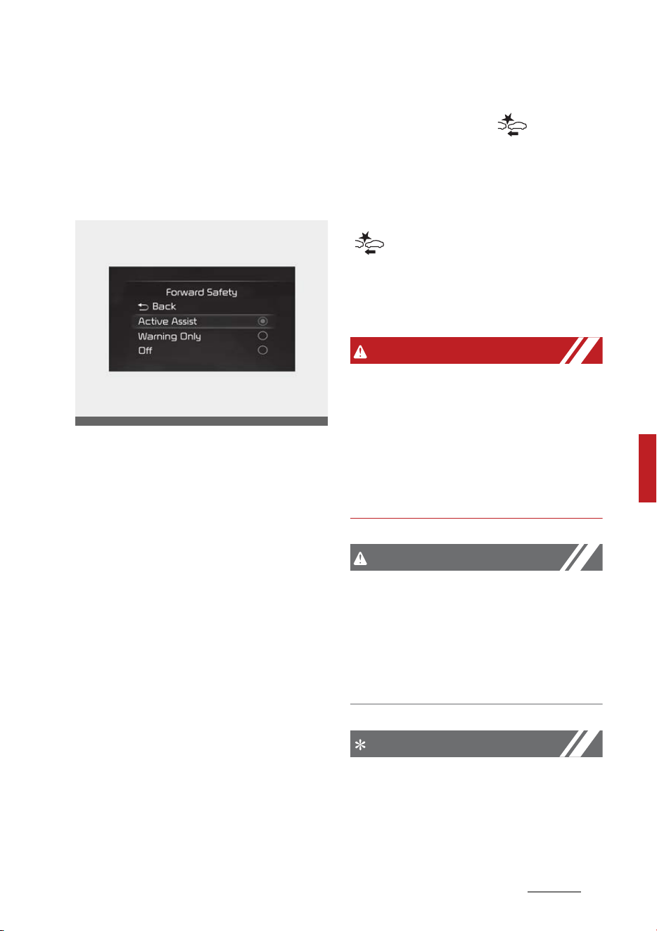
61
6
6
Driving your vehicle Forward Collision-Avoidance Assist (FCA) (Front
view camera only)
Forward Collision-Avoidance Assist
Settings
Setting
Forward Safety
With the ENGINE START/STOP but
-
ton in the ON position, select or
deselect 'Driver Assistance → For
-
ward Safety' from the Settings
menu to set whether or not to use
each function.
䳜 If 'Active Assist' is selected, the
function will warn the driver with
a warning message, an audible
warning and steering wheel vibra
-
tion depending on the collision risk
levels. Braking assist will be
applied depending on the collision
risk.
䳜 If 'Warning Only' is selected, the
function will warn the driver with
a warning message, an audible
warning and steering wheel vibra
-
tion depending on the collision risk
levels. Braking will not be assisted.
䳜 If 'Off' is selected, the function will
be turned off. The( )warning
light will illuminate on the cluster.
The driver can monitor Forward Col
-
lision-Avoidance Assist ON/OFF sta
-
tus from the Settings menu. If the
( )warning light remains ON
when the function is ON, have the
function be inspected by an autho
-
rized Kia dealer.
WARNING
When the engine is restarted, For
-
ward Collision-Avoidance Assist will
always turn on. However, if 'Off' is
selected after the engine is
restarted, the driver should always
be aware of the surroundings and
drive safely.
CAUTION
䳜 If 'Warning Only' is selected, brak
-
ing is not assisted.
䳜 Steering wheel vibration can be
turned on or off. Select or dese
-
lect 'Driver Assistance → Haptic
Warning' from the Settings menu.
NOTICE
Forward Collision-Avoidance Assist
will turn off when ESC is turned off
by pressing and holding the ESC OFF
OMQ4AH050344
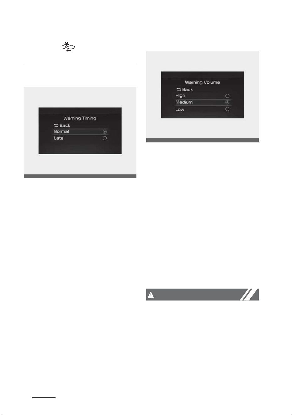
Driving your vehicle
626
Forward Collision-Avoidance Assist (FCA) (Front
view camera only)
button. The( )warning light will
illuminate on the cluster.
Warning Timing
With the ENGINE START/STOP but
-
ton in the ON position, select 'Driver
Assistance → Warning Timing' from
the Settings menu to change the
initial warning activation time for
Forward Collision-Avoidance Assist.
When the vehicle is first delivered,
Warning Timing is set to 'Normal'. If
you change the Warning Timing, the
warning time of other Driver Assis
-
tance systems may change.
Warning Volume
With the ENGINE START/STOP but
-
ton in the ON position, select 'Driver
Assistance → Warning Volume' from
the Settings menu to change the
Warning Volume to 'High', 'Medium',
'Low' or 'Off' for Forward Collision-
Avoidance Assist.
However, even if 'Off' is selected,
Forward Collision-Avoidance Assist
Warning Volume will not turn off but
the volume will sound as 'Low'.
If you change the Warning Volume,
the Warning Volume of other Driver
Assistance systems may change.
CAUTION
䳜 The setting of the Warning Timing
and Warning Volume applies to all
functions of Forward Collision-
Avoidance Assist.
䳜 Even though 'Normal' is selected
for Warning Timing, if the front
vehicle suddenly stops, the initial
warning activation time may
seem late.
OMQ4AH050334
OMQ4041606
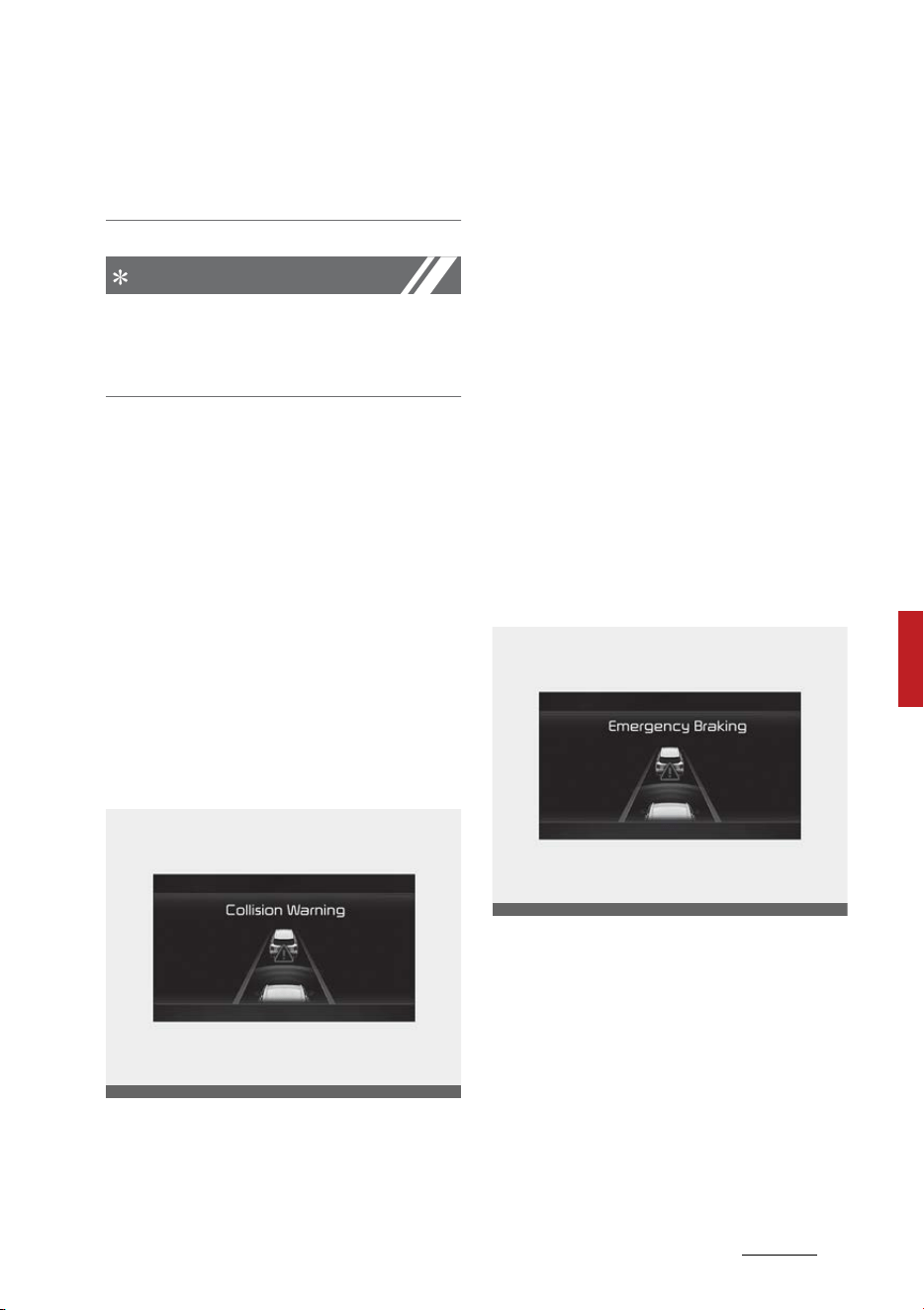
63
6
6
Driving your vehicle Forward Collision-Avoidance Assist (FCA) (Front
view camera only)
䳜 Select 'Late' for Warning Timing
when traffic is light and when
driving speed is slow.
NOTICE
If the engine is restarted, Warning
Timing and Warning Volume will
maintain the last setting.
Forward Collision-Avoidance Assist
Operation
warning and control
The basic function for Forward Colli
-
sion-Avoidance Assist is to warn and
control the vehicle depending on the
collision level: 'Collision Warning',
'Emergency Braking' and 'Stopping
vehicle and ending brake control'.
Collision Warning
䳜 To warn the driver of a collision,
the 'Collision Warning' warning
message will appear on the clus
-
ter, an audible warning will sound
and the steering wheel will
vibrate.
䳜 If a vehicle is detected in front,
the function will operate when
your vehicle speed is between
approximately 6 ~ 112 mph (10 ~
180 km/h).
䳜 If a pedestrian is detected in
front, the function will operate
when your vehicle speed is
between approximately 6 ~ 37
mph (10 ~ 60 km/h).
䳜 If 'Active Assist' is selected, brak
-
ing may be assisted.
Emergency Braking
䳜 To warn the driver that emer
-
gency braking will be assisted, the
'Emergency Braking' warning
message will appear on the clus
-
ter, an audible warning will sound
and the steering wheel will
vibrate.
䳜 If a vehicle is detected in front,
the function will operate when
your vehicle speed is between
OMQ4050071L
OMQ4050072L
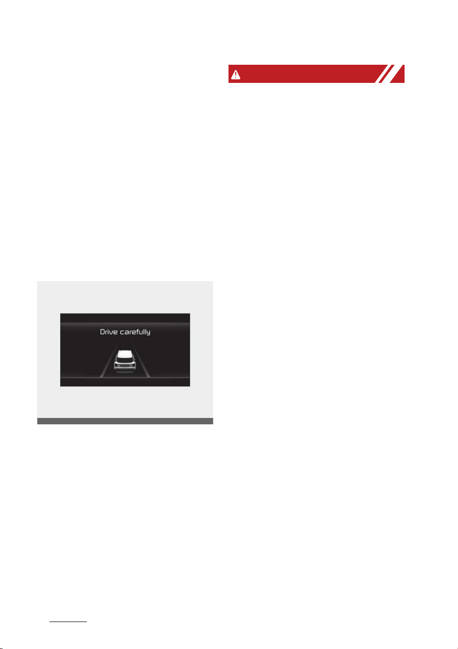
Driving your vehicle
646
Forward Collision-Avoidance Assist (FCA) (Front
view camera only)
approximately 6 ~ 37 mph (10 ~
60 km/h).
䳜 If a pedestrian is detected in
front, the function will operate
when your vehicle speed is
between approximately 6 ~ 37
mph (10 ~ 60 km/h).
䳜 In emergency braking situation,
braking is assisted with strong
braking power by the function to
help prevent collision with the
vehicle or pedestrian.
Stopping vehicle and ending brake
control
䳜 When the vehicle is stopped due
to emergency braking, the 'Drive
carefully' warning message will
appear on the cluster.
䳜 For your safety, the driver should
depress the brake pedal immedi
-
ately and check the surroundings.
䳜 Brake control will end after the
vehicle is stopped by emergency
braking for approximately 2 sec
-
onds.
WARNING
䳜 For your safety, change the Set
-
tings after parking the vehicle at a
safe location.
䳜 With 'Active Assist' or 'Warning
Only' selected, when ESC is turned
off by pressing and holding the
ESC OFF button, Forward Colli
-
sion-Avoidance Assist will turn off
automatically. In this case, the
function cannot be set from the
Settings menu and the warning
light will illuminate on the cluster
which is normal. If ESC is turned
on by pressing the ESC OFF but
-
ton, Forward Collision-Avoidance
Assist will maintain the last set
-
ting.
䳜 Forward Collision-Avoidance
Assist does not operate in all situ
-
ations or cannot avoid all colli
-
sions.
䳜 The driver should hold the
responsibility to control the vehi
-
cle. Do not solely depend on For
-
ward Collision-Avoidance Assist.
Rather, maintain a safe braking
distance, and if necessary,
depress the brake pedal to reduce
driving speed or to stop the vehi
-
cle.
䳜 Never deliberately operate For
-
ward Collision-Avoidance Assist
on people, animal, objects, etc. It
may cause serious injury or death.
䳜 Forward Collision-Avoidance
Assist may not operate if the
OMQ4040504L

65
6
6
Driving your vehicle Forward Collision-Avoidance Assist (FCA) (Front
view camera only)
driver depresses the brake pedal
to avoid collision.
䳜 Depending on the road and driving
conditions, Forward Collision-
Avoidance Assist may warn the
driver late or may not warn the
driver.
䳜 During Forward Collision-Avoid
-
ance Assist operation, the vehicle
may stop suddenly injuring pas
-
sengers and shifting loose
objects. Always have the seat belt
on and keep loose objects
secured.
䳜 If any other function's warning
message is displayed or audible
warning is generated, Forward
Collision-Avoidance Assist warn
-
ing message may not be dis
-
played and audible warning may
not be generated.
䳜 You may not hear the warning
sound of Forward Collision-Avoid
-
ance Assist if the surrounding is
noisy.
䳜 Forward Collision-Avoidance
Assist may turn off or may not
operate properly or may operate
unnecessarily depending on the
road conditions and the surround
-
ings.
NOTICE
䳜 Even if there is a problem with
Forward Collision-Avoidance
Assist, the vehicle's basic braking
performance will operate nor
-
mally.
䳜 During emergency braking, brak
-
ing control by the function will
automatically cancel when the
driver excessively depresses the
accelerator pedal or sharply
steers the vehicle.
CAUTION
Depending on the condition of the
vehicle, pedestrian in front and the
surroundings, the speed range to
operate Forward Collision-Avoidance
Assist may reduce. The function
may only warn the driver, or the
function may not operate.
NOTICE
In a situation collision is imminent,
braking may be assisted by Forward
Collision-Avoidance Assist when
braking is insufficient by the driver.
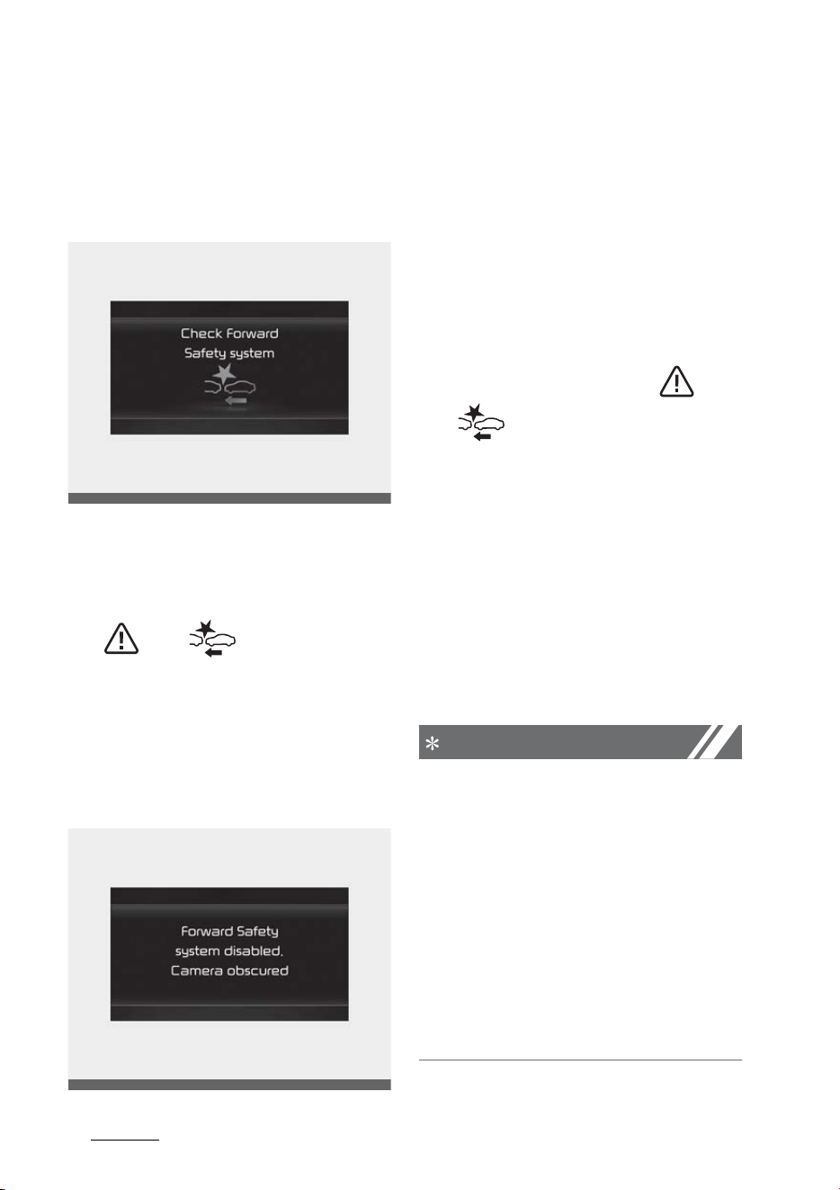
Driving your vehicle
666
Forward Collision-Avoidance Assist (FCA) (Front
view camera only)
Forward Collision-Avoidance Assist
Malfunction and Limitations
Forward Collision-Avoidance Assist
malfunction
When Forward Collision-Avoidance
Assist is not working properly, the
'Check Forward Safety system'
warning message will appear, and
the( ) and( )warning lights
will illuminate on the cluster. Have
the function be inspected by an
authorized Kia dealer.
Forward Collision-Avoidance Assist
disabled
When the front windshield where
the front view camera is located, is
covered with foreign material, such
as snow or rain, it can reduce the
detecting performance and tempo
-
rarily limit or disable Forward Colli
-
sion-Avoidance Assist.
If this occurs, the 'Forward Safety
Function disabled. Camera obscured'
warning message, and the( )
and( )warning lights will illumi
-
nate on the cluster.
The function will operate normally
when snow, rain or foreign matter is
removed. Always keep it clean.
If the function does not operate
normally after obstruction (snow,
rain, or foreign material) is removed,
have the function be inspected by
an authorized Kia dealer.
NOTICE
䳜 Even though the warning mes
-
sage or warning light does not
appear on the cluster, Forward
Collision-Avoidance Assist may
not properly operate.
䳜 Forward Collision-Avoidance
Assist may not properly operate
in an area (e.g. open terrain),
where any substance are not
detected after turning ON the
engine.
OMQ4050074L
OMQ4050073L

67
6
6
Driving your vehicle Forward Collision-Avoidance Assist (FCA) (Front
view camera only)
Limitations of Forward Collision-
Avoidance Assist
Forward Collision-Avoidance Assist
may not operate normally, or the
function may operate unexpectedly
under the following circumstances:
䳜 The detecting sensor or the sur
-
roundings are contaminated or
damaged
䳜 The temperature around the
front view camera is high or low
䳜 The camera lens is contaminated
due to tinted, filmed or coated
windshield, damaged glass, or
stuck of foreign material (sticker,
bug, etc.) on the glass
䳜 Moisture is not removed or frozen
on the windshield
䳜 Washer fluid is continuously
sprayed, or the wiper is on
䳜 Driving in heavy rain or snow, or
thick fog
䳜 The field of view of the front view
camera is obstructed by sun glare
䳜 Street light or light from an
oncoming vehicle is reflected on
the wet road surface, such as a
puddle on the road
䳜 An object is placed on the dash
-
board
䳜 Your vehicle is being towed
䳜 The surrounding is very bright
䳜 The surrounding is very dark, such
as in a tunnel, etc.
䳜 The brightness changes sud
-
denly, for example when entering
or exiting a tunnel
䳜 The brightness outside is low, and
the headlamps are not on or are
not bright
䳜 Driving through steam, smoke or
shadow
䳜 Only part of the vehicle, pedes
-
trian is detected
䳜 The vehicle in front is a bus, heavy
truck, truck with a unusually
shaped luggage, trailer, etc.
䳜 The vehicle in front has no tailla
-
mps, taillamps are located unusu
-
ally, etc.
䳜 The brightness outside is low, and
the taillamps are not on or are not
bright
䳜 The rear of the front vehicle is
small or the vehicle does not look
normal, such as when the vehicle
is tilted, overturned, or the side of
the vehicle is visible, etc.
䳜 The front vehicle's ground clear
-
ance is low or high
䳜 A vehicle or pedestrian suddenly
cuts in front
䳜 The vehicle in front is detected
late
䳜 The vehicle in front is suddenly
blocked by a obstacle
䳜 The vehicle in front suddenly
changes lane or suddenly reduces
speed
䳜 The vehicle in front is bent out of
shape
䳜 The front vehicle's speed is fast or
slow

Driving your vehicle
686
Forward Collision-Avoidance Assist (FCA) (Front
view camera only)
䳜 The vehicle in front steers in the
opposite direction of your vehicle
to avoid a collision
䳜 With a vehicle in front, your vehi
-
cle changes lane at low speed
䳜 The vehicle in front is covered
with snow
䳜 You are departing or returning to
the lane
䳜 Unstable driving
䳜 You are on a roundabout and the
vehicle in front is not detected
䳜 You are continuously driving in a
circle
䳜 The vehicle in front has an
unusual shape
䳜 The vehicle in front is driving
uphill or downhill.
䳜 The pedestrian is not fully
detected, for example, if the
pedestrian is leaning over or is not
fully walking upright
䳜 The pedestrian is wearing clothing
or equipment that makes it diffi
-
cult to detect as a pedestrian
Following image shows the image the
sensor recognizes as vehicle and
pedestrian.
䳜 The pedestrian in front is moving
very quickly
䳜 The pedestrian in front is short or
is posing a low posture
䳜 The pedestrian in front has
impaired mobility
䳜 The pedestrian in front is moving
intersected with the driving direc
-
tion
䳜 There is a group of pedestrians or
a large crowd in front
䳜 The pedestrian is wearing clothing
that easily blends into the back
-
ground, making it difficult to
detect
䳜 The pedestrian is difficult to dis
-
tinguish from the similar shaped
structure in the surroundings
䳜 You are driving by a pedestrian,
traffic signs, structures, etc. near
the intersection
䳜 You are driving by a pedestrian,
traffic signs, structures, etc. near
the intersection
䳜 Driving in a parking lot
䳜 Driving through a tollgate, con
-
struction area, unpaved road, par
-
tial paved road, uneven road,
speed bumps, etc.
䳜 Driving on an incline road, curved
road, etc.
䳜 Driving through a roadside with
trees or streetlights
䳜 The adverse road conditions
cause excessive vehicle vibrations
while driving
OJA040544
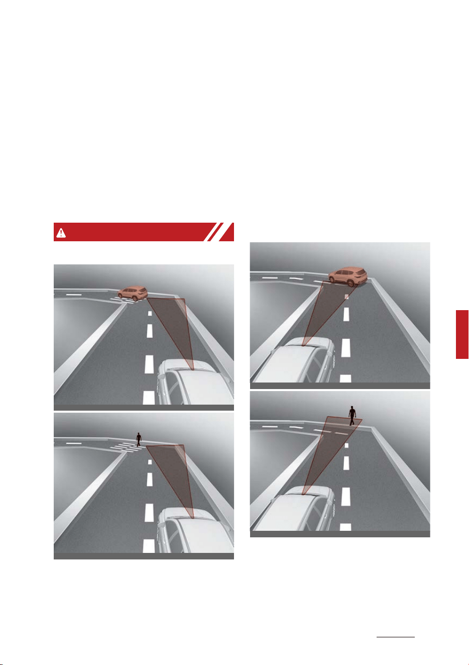
69
6
6
Driving your vehicle Forward Collision-Avoidance Assist (FCA) (Front
view camera only)
䳜 Your vehicle height is low or high
due to heavy loads, abnormal tire
pressure, etc.
䳜 Driving through a narrow road
where trees or grass or over
-
grown
䳜 There is interference by electro
-
magnetic waves, such as driving in
an area with strong radio waves
or electrical noise
WARNING
䳜 Driving on a curved road
Forward Collision-Avoidance
Assist may not detect other vehi
-
cles, pedestrians in front of you
on curved roads adversely affect
-
ing the performance of the sen
-
sors. This may result in no
warning, braking assist or steer
-
ing assist when necessary.
When driving on a curve, you
must maintain a safe braking dis
-
tance, and if necessary, steer the
vehicle and depress the brake
pedal to reduce your driving speed
in order to maintain a safe dis
-
tance.
Forward Collision-Avoidance
Assist may detect a vehicle,
pedestrian in the next lane or
outside the lane when driving on a
curved road.
OCD059189
OCD059188
OCD059191
OCD059190
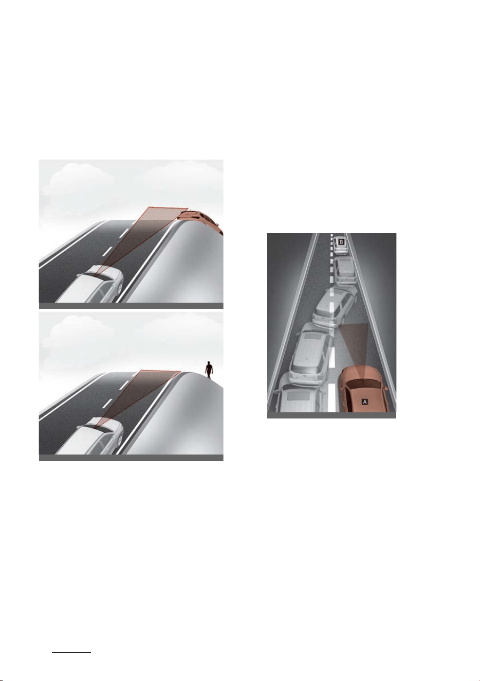
Driving your vehicle
706
Forward Collision-Avoidance Assist (FCA) (Front
view camera only)
If this occurs, the function may
unnecessarily warn the driver and
control the brake or steering
wheel. Always check the traffic
conditions around the vehicle.
䳜 Driving on a sloped road
Forward Collision-Avoidance
Assist may not detect other vehi
-
cles, pedestrians in front of you
while driving uphill or downhill
adversely affecting the perfor
-
mance of the sensors.
This may result in unnecessary
warning, braking assist or steer
-
ing assist or no warning, braking
assist or steering assist when
necessary.
Also, vehicle speed may rapidly
decrease when a vehicle or pedes
-
trian ahead is suddenly detected.
Always have your eyes on the
road while driving uphill or down
-
hill and if necessary, steer your
vehicle and depress the brake
pedal to reduce your driving speed
in order to maintain a safe dis
-
tance.
䳜 Changing lanes
[A]: Your vehicle
[B]: Lane changing vehicle
When a vehicle [B] moves into
your lane from an adjacent lane, it
cannot be detected by the sensor
until it is in the sensor's detection
range. Forward Collision-Avoid
-
ance Assist may not immediately
detect the vehicle when the vehi
-
cle changes lanes abruptly. In this
case, you must maintain a safe
braking distance, and if neces
-
sary, steer your vehicle and
depress the brake pedal to reduce
ODL3059040
OCD059192
OADAS032SDY
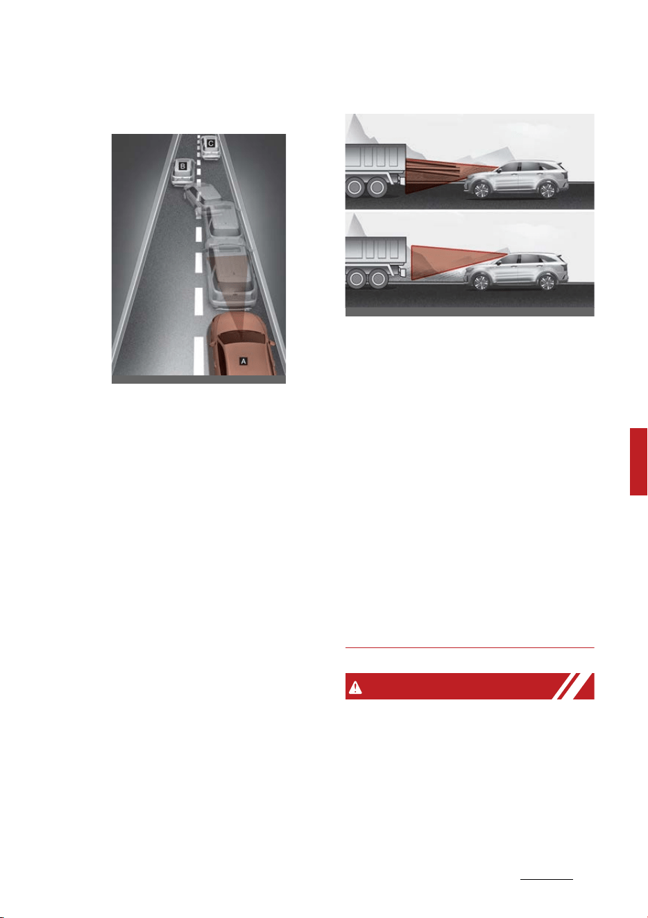
71
6
6
Driving your vehicle Forward Collision-Avoidance Assist (FCA) (Front
view camera only)
your driving speed in order to
maintain a safe distance.
[A]: Your vehicle
[B]: Lane changing vehicle,
[C]: Same lane vehicle
When a vehicle [B] in front of you
merges out of the lane, Forward
Collision-Avoidance Assist may
not immediately detect the vehi
-
cle [C] that is now in front of you.
In this case, you must maintain a
safe braking distance, and if nec
-
essary, steer your vehicle and
depress the brake pedal to reduce
your driving speed in order to
maintain a safe distance.
䳜 Detecting vehicle
If the vehicle in front of you has
cargo that extends rearward from
the cab, or when the vehicle in
front of you has higher ground
clearance, additional special
attention is required. Forward
Collision-Avoidance Assist may
not be able to detect the cargo
extending from the vehicle. In
these instances, you must main
-
tain a safe braking distance from
the rearmost object, and if neces
-
sary, steer your vehicle and
depress the brake pedal to reduce
your driving speed in order to
maintain distance.
WARNING
䳜 When you are towing a trailer or
another vehicle, we recommend
that Forward Collision-Avoidance
Assist is turned off due to safety
reasons.
䳜 Forward Collision-Avoidance
Assist may operate if objects that
OADAS033SDY
OMQ4H050008

Driving your vehicle
726
Forward Collision-Avoidance Assist (FCA) (Front
view camera only)
are similar in shape or character
-
istics to vehicles and pedestrians
are detected.
䳜 Forward Collision-Avoidance
Assist does not operate on
motorcycles, or smaller wheeled
objects, such as luggage bags,
shopping carts, or strollers that
are dragged by a pedestrian.
䳜 Forward Collision-Avoidance
Assist may not operate normally
if interfered by strong electro
-
magnetic waves.
䳜 Forward Collision-Avoidance
Assist may not operate for
approximately 15 seconds after
the vehicle is started, or the front
view camera is initialized.
This device complies with Part 15
of the FCC rules.
Operation is subject to the following
three conditions:
1. This device may not cause harm
-
ful interference.
2. This device must accept any
interference received, including
interference that may cause
undesired operation.
3. Changes or modifications not
expressly approved by the party
responsible for compliance could
void the user's authority to oper
-
ate the device.
Radio frequency radiation exposure
information:
This equipment complies with FCC
radiation exposure limits set forth
for an uncontrolled environment.
This equipment should be installed
and operated with minimum dis
-
tance of 8 in (20 cm) between the
radiator (antenna) and your body.
This transmitter must not be colo
-
cated or operating in conjunction
with any other antenna or trans
-
mitter.
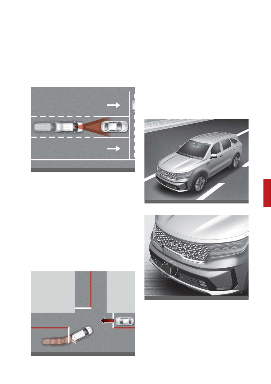
73
6
6
Driving your vehicle Forward Collision-Avoidance Assist (FCA)
(Sensor fusion)
Forward Collision-Avoidance
Assist (FCA) (Sensor fusion) (if
equipped)
Basic function
Forward Collision-Avoidance Assist
is designed to help detect and moni
-
tor the vehicle ahead or help detect
a pedestrian or cyclist in the road
-
way and warn the driver that a colli
-
sion is imminent with a warning
message and an audible warning,
and if necessary, apply emergency
braking.
Junction Turning function
Junction Turning function will help
avoid a collision with an oncoming
vehicle in an adjacent lane when
turning left at a crossroad with the
turn signal on by applying emer
-
gency braking.
Detecting sensor
Front view camera
Front radar
Refer to the picture above for the
detailed location of the detecting
sensors.
OMQ4050280L
OMQ4AH051241L
OMQ4H051009
OMQ4051077
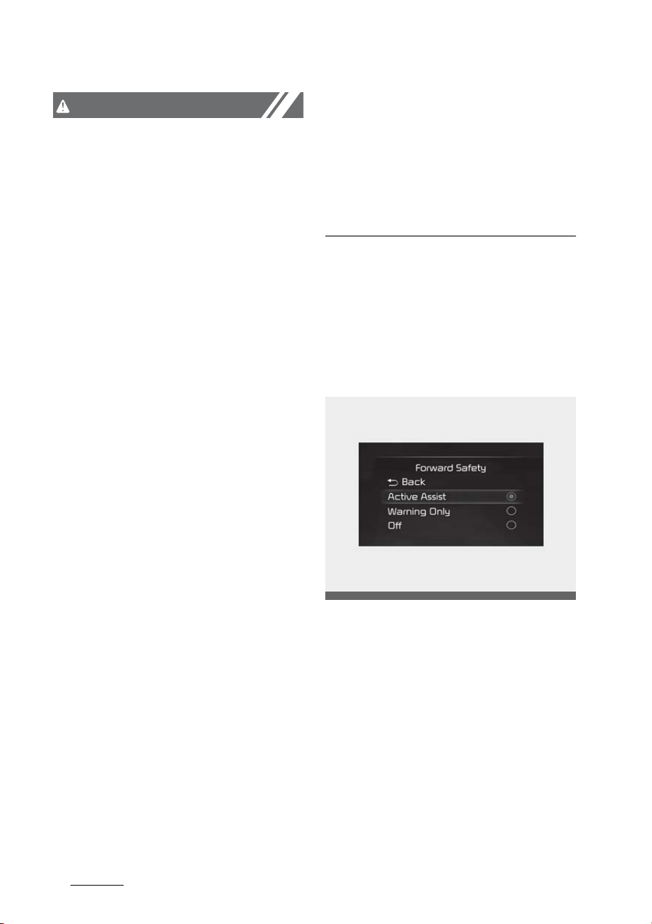
Driving your vehicle
746
Forward Collision-Avoidance Assist (FCA) (Sensor
fusion)
CAUTION
Take the following precautions to
maintain optimal performance of
the detecting sensor:
䳜 Never disassemble the detecting
sensor or sensor assembly, or
apply any impact on it.
䳜 Never install any accessories or
stickers on the front windshield,
or tint the front windshield.
䳜 If the detecting sensors have
been replaced or repaired, have
the vehicle be inspected by an
authorized Kia dealer.
䳜 Pay extreme caution to keep the
front view camera dry.
䳜 Never place any reflective objects
(i.e. white paper, mirror) over the
dashboard. Any light reflection
may prevent the function from
functioning properly.
䳜 Do not apply license plate frame
or objects, such as a bumper
sticker, film or a bumper guard,
near the front radar cover.
䳜 Always keep the front radar and
cover clean and free of dirt and
debris. Use only a soft cloth to
wash the vehicle. Do not spray
pressurized water directly on the
sensor or sensor cover.
䳜 If unnecessary force has been
applied to the radar or around the
radar, Forward Collision-Avoid
-
ance Assist may not properly
operate even though a warning
message does not appear on the
cluster. Have the vehicle be
inspected by an authorized Kia
dealer.
䳜 Use only genuine parts to repair
or replace a damaged front radar
cover. Do not apply paint to the
front radar cover.
Forward Collision-Avoidance Assist
Settings
Setting
Forward Safety
With the ENGINE START/STOP but
-
ton in the ON position, select or
deselect 'Driver Assistance → For
-
ward Safety' from the Settings
menu to set whether or not to use
each function.
䳜 If 'Active Assist' is selected, the
function will warn the driver with
a warning message, an audible
warning and steering wheel vibra
-
tion depending on the collision risk
levels. Braking assist will be
OMQ4AH050344
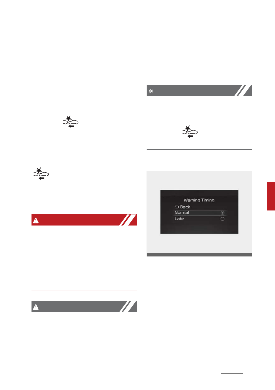
75
6
6
Driving your vehicle Forward Collision-Avoidance Assist (FCA)
(Sensor fusion)
applied depending on the collision
risk.
䳜 If 'Warning Only' is selected, the
function will warn the driver with
a warning message, an audible
warning and steering wheel vibra
-
tion depending on the collision risk
levels. Braking will not be assisted.
䳜 If 'Off' is selected, the function will
off. The( )warning light will
illuminate on the cluster.
The driver can monitor Forward Col
-
lision-Avoidance Assist ON/OFF sta
-
tus from the Settings menu. If the
( )warning light remains ON
when the function is ON, have the
function be inspected by an autho
-
rized Kia dealer.
WARNING
When the engine is restarted, For
-
ward Collision-Avoidance Assist will
always turn on. However, if 'Off' is
selected after the engine is
restarted, the driver should always
be aware of the surroundings and
drive safely.
CAUTION
䳜 If 'Warning Only' is selected, brak
-
ing is not assisted.
䳜 The settings for Forward Safety
include 'Basic function' and 'Junc
-
tion Turning'.
䳜 Steering wheel vibration can be
turned on or off. Select or dese
-
lect 'Driver Assistance → Haptic
Warning' from the Settings menu.
NOTICE
Forward Collision-Avoidance Assist
will turn off when ESC is turned off
by pressing and holding the ESC OFF
button. The( )warning light will
illuminate on the cluster.
Warning Timing
With the ENGINE START/STOP but
-
ton in the ON position, select 'Driver
Assistance → Warning Timing' from
the Settings menu to change the
initial warning activation time for
Forward Collision-Avoidance Assist.
When the vehicle is first delivered,
Warning Timing is set to 'Normal'.
If you change the Warning Timing,
the warning time of other Driver
Assistance systems may change.
OMQ4AH050334
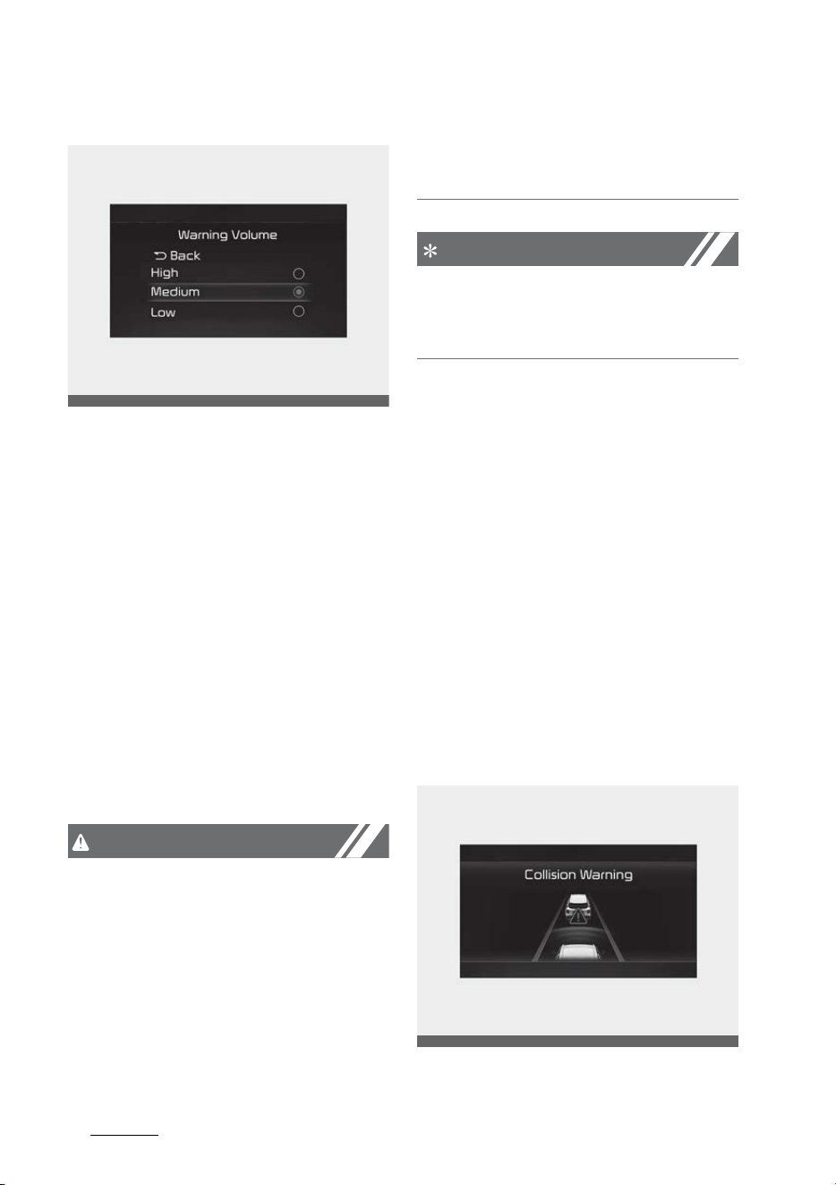
Driving your vehicle
766
Forward Collision-Avoidance Assist (FCA) (Sensor
fusion)
Warning Volume
With the ENGINE START/STOP but
-
ton in the ON position, select 'Driver
Assistance → Warning Volume' from
the Settings menu to change the
Warning Volume to 'High', 'Medium',
'Low' or 'Off' for Forward Collision-
Avoidance Assist.
However, even if 'Off' is selected,
Forward Collision-Avoidance Assist
Warning Volume will not turn off but
the volume will sound as 'Low'.
If you change the Warning Volume,
the Warning Volume of other Driver
Assistance systems may change.
CAUTION
䳜 The setting of the Warning Timing
and Warning Volume applies to all
functions of Forward Collision-
Avoidance Assist.
䳜 Even though 'Normal' is selected
for Warning Timing, if the front
vehicle suddenly stops, the initial
warning activation time may
seem late.
䳜 Select 'Late' for Warning Timing
when traffic is light and when
driving speed is slow.
NOTICE
If the engine is restarted, Warning
Timing and Warning Volume will
maintain the last setting.
Forward Collision-Avoidance Assist
Operation
Basic function
Warning and control
The basic function for Forward Colli
-
sion-Avoidance Assist is to warn and
control the vehicle depending on the
collision level: 'Collision Warning',
'Emergency Braking' and 'Stopping
vehicle and ending brake control'.
Collision Warning
OMQ4041606
OMQ4051338L
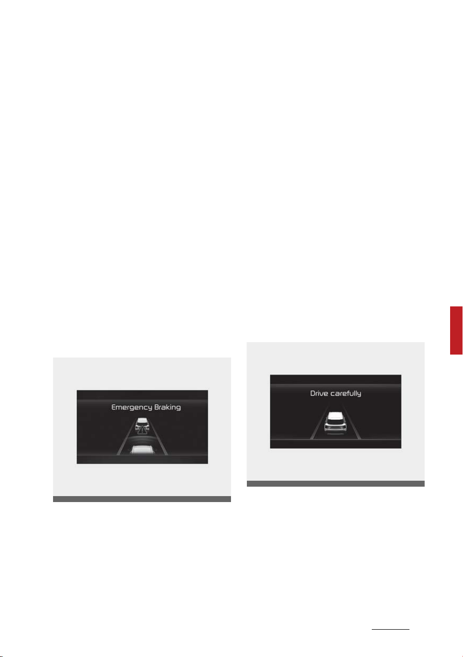
77
6
6
Driving your vehicle Forward Collision-Avoidance Assist (FCA)
(Sensor fusion)
䳜 To warn the driver of a collision,
the 'Collision Warning' warning
message will appear on the clus
-
ter, an audible warning will sound
and the steering wheel will
vibrate.
䳜 If a vehicle is detected in front,
the function will operate when
your vehicle speed is between
approximately 6 ~ 112 mph (10 ~
180 km/h).
䳜 If a pedestrian or cyclist is
detected in front, the function will
operate when your vehicle speed
is between approximately 6 ~ 53
mph (10 ~ 85 km/h).
䳜 If 'Active Assist' is selected, brak
-
ing may be assisted.
Emergency Braking
䳜 To warn the driver that emer
-
gency braking will be assisted, the
'Emergency Braking' warning
message will appear on the clus
-
ter, an audible warning will sound
and the steering wheel will
vibrate.
䳜 If a vehicle is detected in front,
the function will operate when
your vehicle speed is between
approximately 6 ~ 47 mph (10 ~
75 km/h).
䳜 If a pedestrian or cyclist is
detected in front, the function will
operate when your vehicle speed
is between approximately 6 ~ 40
mph (10 ~ 65 km/h).
䳜 In emergency braking situation,
braking is assisted with strong
braking power by the function to
help prevent collision with the
vehicle, pedestrian or cyclist
ahead.
Stopping vehicle and ending brake
control
䳜 When the vehicle is stopped due
to emergency braking, the 'Drive
carefully' warning message will
appear on the cluster.
For your safety, the driver should
depress the brake pedal immedi
-
ately and check the surroundings.
OMQ4050072L
OMQ4040504L
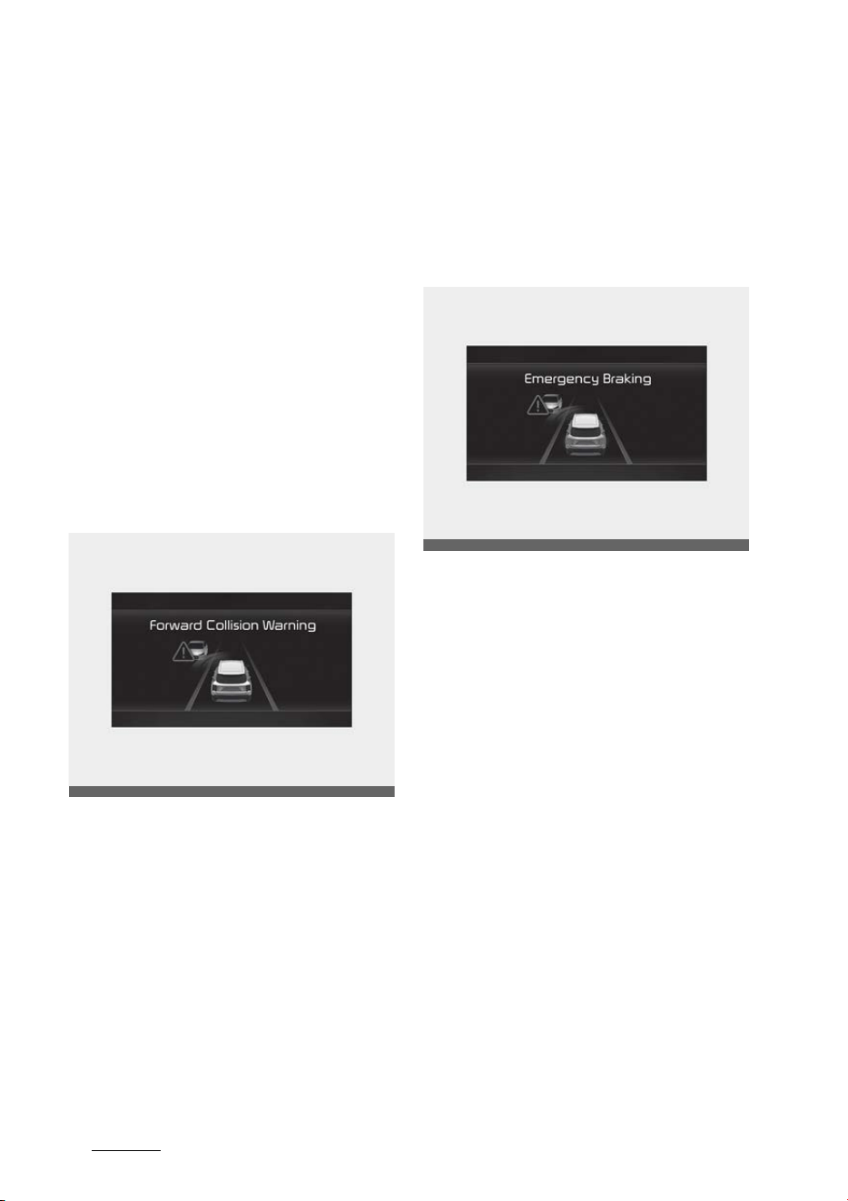
Driving your vehicle
786
Forward Collision-Avoidance Assist (FCA) (Sensor
fusion)
䳜 Brake control will end after the
vehicle is stopped by emergency
braking for approximately 2 sec
-
onds.
Junction Turning function
Warning and control
Junction Turning function will warn
and control the vehicle depending on
the collision level: 'Collision Warning',
'Emergency Braking' and 'Stopping
vehicle and ending brake control'.
Collision Warning
䳜 To warn the driver of a collision,
the 'Collision Warning' warning
message will appear on the clus
-
ter, an audible warning will sound
and the steering wheel will
vibrate.
䳜 The function will operate when
your vehicle speed is between
approximately 6 ~ 19 mph (10 ~
30 km/h) and the oncoming vehi
-
cle speed is between approxi
-
mately 19 ~ 44 mph (30 ~ 70 km/
h).
䳜 If 'Active Assist' is selected, brak
-
ing may be assisted.
Emergency Braking
䳜 To warn the driver that emer
-
gency braking will be assisted, the
'Emergency Braking' warning
message will appear on the clus
-
ter, an audible warning will sound
and the steering wheel will
vibrate.
䳜 The function will operate when
your vehicle speed is between
approximately 6 ~ 19 mph (10 ~
30 km/h) and the oncoming vehi
-
cle speed is between approxi
-
mately 19 ~ 44 mph (30 ~ 70 km/
h).
䳜 In emergency braking situation,
braking is assisted with strong
braking power by the function to
help prevent collision with the
oncoming vehicle.
OMQ4050212L
OMQ4050211L
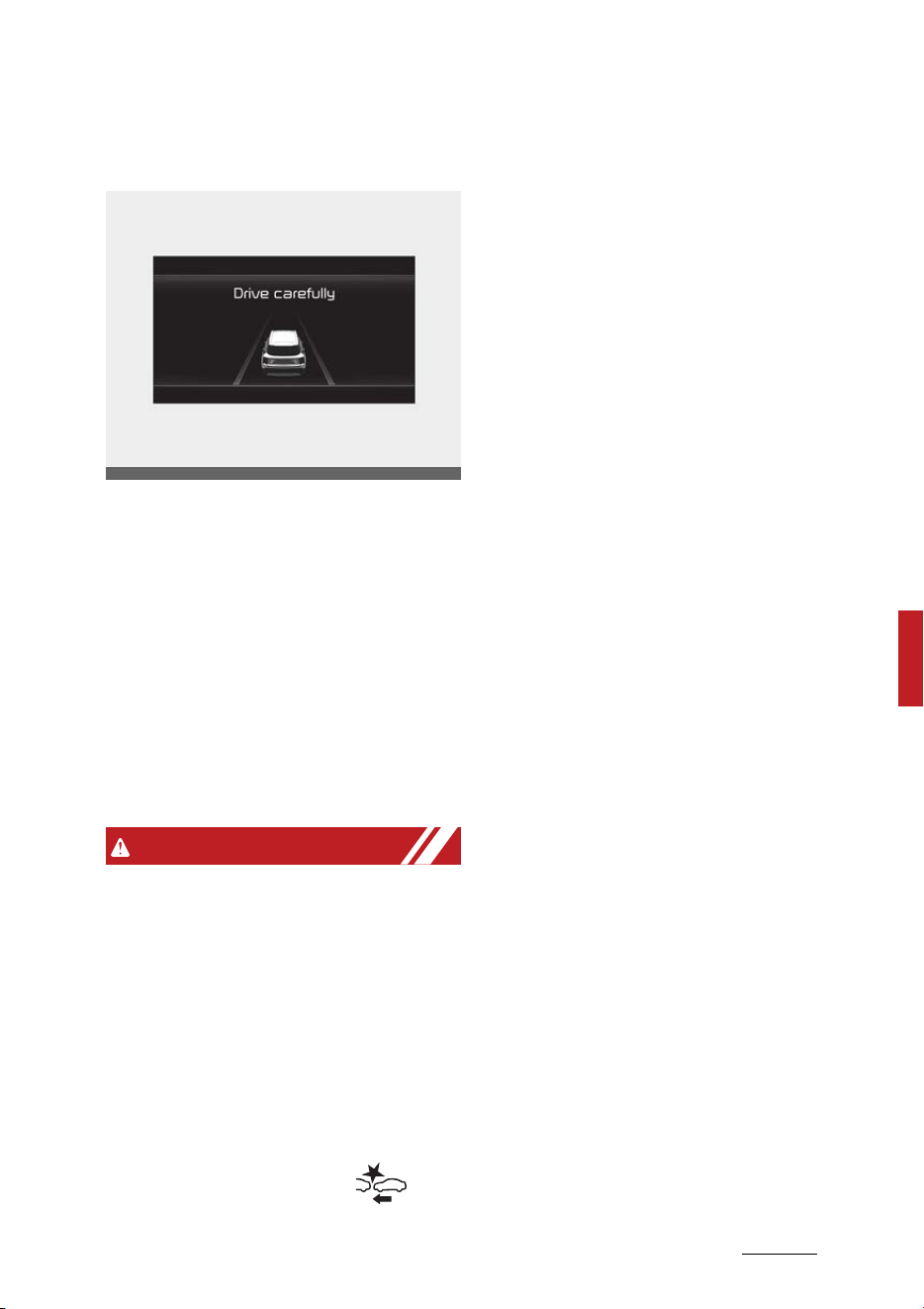
79
6
6
Driving your vehicle Forward Collision-Avoidance Assist (FCA)
(Sensor fusion)
Stopping vehicle and ending brake
control
䳜 When the vehicle is stopped due
to emergency braking, the 'Drive
carefully' warning message will
appear on the cluster.
For your safety, the driver should
depress the brake pedal immedi
-
ately and check the surroundings.
䳜 Brake control will end after the
vehicle is stopped by emergency
braking for approximately 2 sec
-
onds.
WARNING
䳜 For your safety, change the Set
-
tings after parking the vehicle at a
safe location.
䳜 With 'Active Assist' or 'Warning
Only' selected, when ESC is turned
off by pressing and holding the
ESC OFF button, Forward Colli
-
sion-Avoidance Assist will turn off
automatically. In this case, the
function cannot be set from the
Settings menu and the
warning light will illuminate on the
cluster which is normal. If ESC is
turned on by pressing the ESC
OFF button, Forward Collision-
Avoidance Assist will maintain the
last setting.
䳜 Forward Collision-Avoidance
Assist does not operate in all situ
-
ations or cannot avoid all colli
-
sions.
䳜 The driver should hold the
responsibility to control the vehi
-
cle. Do not solely depend on For
-
ward Collision-Avoidance Assist.
Rather, maintain a safe braking
distance, and if necessary,
depress the brake pedal to reduce
driving speed or to stop the vehi
-
cle.
䳜 Never deliberately operate For
-
ward Collision-Avoidance Assist
on people, animal, objects, etc. It
may cause serious injury or death.
䳜 Forward Collision-Avoidance
Assist may not operate if the
driver depresses the brake pedal
to avoid collision.
䳜 Depending on the road and driving
conditions, Forward Collision-
Avoidance Assist may warn the
driver late or may not warn the
driver.
䳜 During Forward Collision-Avoid
-
ance Assist operation, the vehicle
may stop suddenly injuring pas
-
sengers and shifting loose
objects. Always have the seat belt
OMQ4040504L

Driving your vehicle
806
Forward Collision-Avoidance Assist (FCA) (Sensor
fusion)
on and keep loose objects
secured.
䳜 If any other function's warning
message is displayed or audible
warning is generated, Forward
Collision-Avoidance Assist warn
-
ing message may not be dis
-
played and audible warning may
not be generated.
䳜 You may not hear the warning
sound of Forward Collision-Avoid
-
ance Assist if the surrounding is
noisy.
䳜 Forward Collision-Avoidance
Assist may turn off or may not
operate properly or may operate
unnecessarily depending on the
road conditions and the surround
-
ings.
WARNING
䳜 Even if there is a problem with
Forward Collision-Avoidance
Assist, the vehicle's basic braking
performance will operate nor
-
mally.
䳜 During emergency braking, brak
-
ing control by the function will
automatically cancel when the
driver excessively depresses the
accelerator pedal or sharply
steers the vehicle.
CAUTION
䳜 Depending on the condition of the
vehicle, pedestrian and cyclist in
front and the surroundings, the
speed range to operate Forward
Collision-Avoidance Assist may
reduce. The function may only
warn the driver, or the function
may not operate.
䳜 Forward Collision-Avoidance
Assist will operate under certain
conditions by judging the risk level
based on the condition of the
oncoming vehicle, driving direc
-
tion, speed and surroundings.
NOTICE
In a situation collision is imminent,
braking may be assisted by Forward
Collision-Avoidance Assist when
braking is insufficient by the driver.
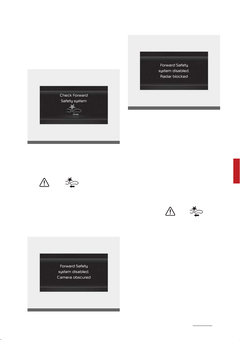
81
6
6
Driving your vehicle Forward Collision-Avoidance Assist (FCA)
(Sensor fusion)
Forward Collision-Avoidance Assist
Malfunction and Limitations
Forward Collision-Avoidance Assist
malfunction
When Forward Collision-Avoidance
Assist is not working properly, the
'Check Forward Safety system'
warning message will appear, and
the ( ) and ( ) warning lights
will illuminate on the cluster. Have
the function be inspected by an
authorized Kia dealer.
Forward Collision-Avoidance Assist
disabled
When the front windshield where
the front view camera is located,
front radar cover, sensor is covered
with foreign material, such as snow
or rain, it can reduce the detecting
performance and temporarily limit
or disable Forward Collision-Avoid
-
ance Assist.
If this occurs the 'Forward Safety
Function disabled. Camera obscured'
or the 'Forward Safety Function dis
-
abled. Radar blocked' warning mes
-
sage, and the ( ) and( )
warning lights will illuminate on the
cluster.
The function will operate normally
when snow, rain or foreign matter is
removed. Always keep it clean.
If the function does not operate
normally after obstruction (snow,
rain, or foreign material) is removed,
have the function be inspected by
an authorized Kia dealer.
OMQ4050074L
OMQ4050073L
OMQ4050079L

Driving your vehicle
826
Forward Collision-Avoidance Assist (FCA) (Sensor
fusion)
WARNING
䳜 Even though the warning mes
-
sage or warning light does not
appear on the cluster, Forward
Collision-Avoidance Assist may
not properly operate.
䳜 Forward Collision-Avoidance
Assist may not properly operate
in an area (e.g. open terrain),
where any substance are not
detected after turning ON the
engine.
Limitations of Forward Collision-
Avoidance Assist
Forward Collision-Avoidance Assist
may not operate normally, or the
function may operate unexpectedly
under the following circumstances:
䳜 The detecting sensor or the sur
-
roundings are contaminated or
damaged
䳜 The temperature around the
front view camera is high or low
䳜 The camera lens is contaminated
due to tinted, filmed or coated
windshield, damaged glass, or
stuck of foreign material (sticker,
bug, etc.) on the glass
䳜 Moisture is not removed or frozen
on the windshield
䳜 Washer fluid is continuously
sprayed, or the wiper is on
䳜 Driving in heavy rain or snow, or
thick fog
䳜 The field of view of the front view
camera is obstructed by sun glare
䳜 Street light or light from an
oncoming vehicle is reflected on
the wet road surface, such as a
puddle on the road
䳜 An object is placed on the dash
-
board
䳜 Your vehicle is being towed
䳜 The surrounding is very bright
䳜 The surrounding is very dark, such
as in a tunnel, etc.
䳜 The brightness changes sud
-
denly, for example when entering
or exiting a tunnel
䳜 The brightness outside is low, and
the headlamps are not on or are
not bright
䳜 Driving through steam, smoke or
shadow
䳜 Only part of the vehicle, pedes
-
trian or cyclist is detected
䳜 The vehicle in front is a bus, heavy
truck, truck with a unusually
shaped luggage, trailer, etc.
䳜 The vehicle in front has no tailla
-
mps, taillamps are located unusu
-
ally, etc.
䳜 The brightness outside is low, and
the taillamps are not on or are not
bright
䳜 The rear of the front vehicle is
small or the vehicle does not look
normal, such as when the vehicle
is tilted, overturned, or the side of
the vehicle is visible, etc.
䳜 The front vehicle's ground clear
-
ance is low or high
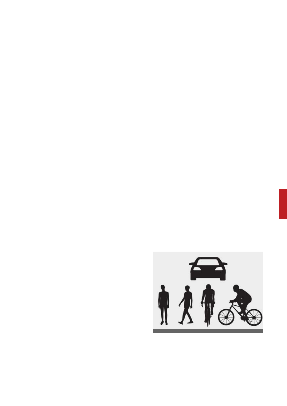
83
6
6
Driving your vehicle Forward Collision-Avoidance Assist (FCA)
(Sensor fusion)
䳜 A vehicle, pedestrian or cyclist
suddenly cuts in front
䳜 The bumper around the front
radar is impacted, damaged or
the front radar is out of position
䳜 The temperature around the
front radar is high or low
䳜 Driving through a tunnel or iron
bridge
䳜 Driving in large areas where there
are few vehicles or structures (i.e.
desert, meadow, suburb, etc.)
䳜 Driving near areas containing
metal substances, such as a con
-
struction zone, railroad, etc.
䳜 A material is near that reflects
very well on the front radar, such
as a guardrail, nearby vehicle, etc.
䳜 The cyclist in front is on a bicycle
made of material that does not
reflect on the front radar
䳜 The vehicle in front is detected
late
䳜 The vehicle in front is suddenly
blocked by a obstacle
䳜 The vehicle in front suddenly
changes lane or suddenly reduces
speed
䳜 The vehicle in front is bent out of
shape
䳜 The front vehicle's speed is fast or
slow
䳜 The vehicle in front steers in the
opposite direction of your vehicle
to avoid a collision
䳜 With a vehicle in front, your vehi
-
cle changes lane at low speed
䳜 The vehicle in front is covered
with snow
䳜 You are departing or returning to
the lane
䳜 Unstable driving
䳜 You are on a roundabout and the
vehicle in front is not detected
䳜 You are continuously driving in a
circle
䳜 The vehicle in front has an
unusual shape
䳜 The vehicle in front is driving
uphill or downhill.
䳜 The pedestrian or cyclist is not
fully detected, for example, if the
pedestrian is leaning over or is not
fully walking upright
䳜 The pedestrian or cyclist is wear
-
ing clothing or equipment that
makes it difficult to detect as a
pedestrian or cyclist
Following image shows the image the
sensor recognizes as vehicle, pedes
-
trian, and cyclist.
䳜 The pedestrian or cyclist in front
is moving very quickly
䳜 The pedestrian or cyclist in front
is short or is posing a low posture
OADAS044
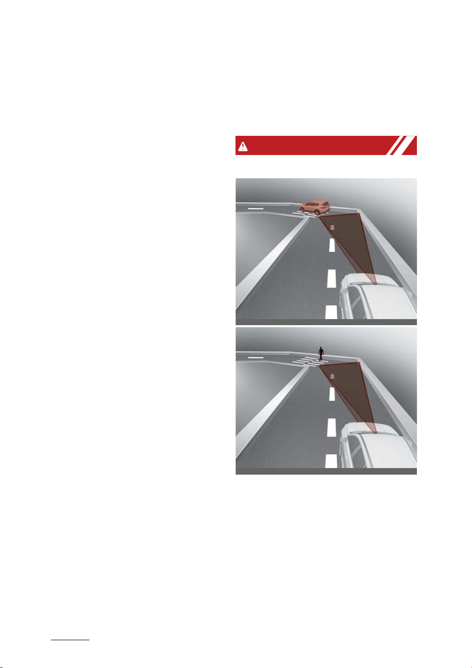
Driving your vehicle
846
Forward Collision-Avoidance Assist (FCA) (Sensor
fusion)
䳜 The pedestrian or cyclist in front
has impaired mobility
䳜 The pedestrian or cyclist in front
is moving intersected with the
driving direction
䳜 There is a group of pedestrians,
cyclists or a large crowd in front
䳜 The pedestrian or cyclist is wear
-
ing clothing that easily blends into
the background, making it difficult
to detect
䳜 The pedestrian or cyclist is diffi
-
cult to distinguish from the simi
-
lar shaped structure in the
surroundings
䳜 You are driving by a pedestrian,
cyclist, traffic signs, structures,
etc. near the intersection
䳜 Driving in a parking lot
䳜 Driving through a tollgate, con
-
struction area, unpaved road, par
-
tial paved road, uneven road,
speed bumps, etc.
䳜 Driving on an incline road, curved
road, etc.
䳜 Driving through a roadside with
trees or streetlights
䳜 Unstable driving
䳜 The adverse road conditions
cause excessive vehicle vibrations
while driving
䳜 Your vehicle height is low or high
due to heavy loads, abnormal tire
pressure, etc.
䳜 Driving through a narrow road
where trees or grass or over
-
grown
䳜 There is interference by electro
-
magnetic waves, such as driving in
an area with strong radio waves
or electrical noise
WARNING
䳜 Driving on a curved road
ODEEV069237NR
ODEEV069238NR
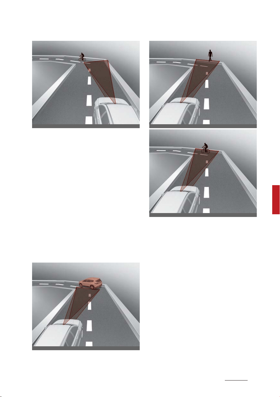
85
6
6
Driving your vehicle Forward Collision-Avoidance Assist (FCA)
(Sensor fusion)
Forward Collision-Avoidance
Assist may not detect other vehi
-
cles, pedestrians or cyclists in
front of you on curved roads
adversely affecting the perfor
-
mance of the sensors. This may
result in no warning, and braking
assist when necessary.
When driving on a curve, you
must maintain a safe braking dis
-
tance, and if necessary, steer the
vehicle and depress the brake
pedal to reduce your driving speed
in order to maintain a safe dis
-
tance.
Forward Collision-Avoidance
Assist may detect a vehicle,
pedestrian or cyclist in the next
lane or outside the lane when
driving on a curved road.
If this occurs, the function may
unnecessarily warn the driver and
control the brake. Always check
the traffic conditions around the
vehicle.
ODEEV069239NR
ODEEV069240NR
ODEEV069241NR
ODEEV069242NR
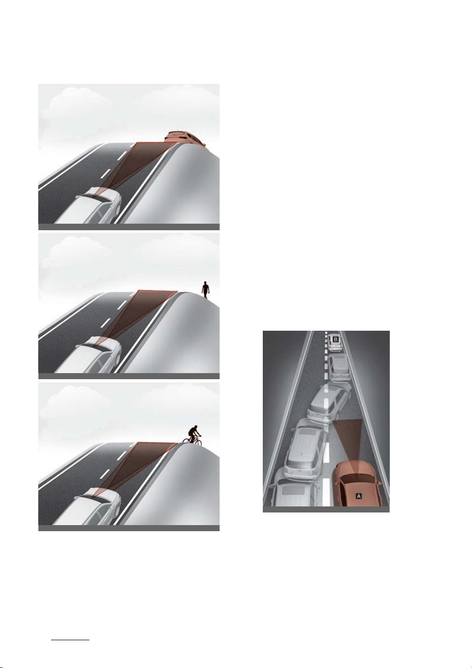
Driving your vehicle
866
Forward Collision-Avoidance Assist (FCA) (Sensor
fusion)
䳜 Driving on a sloped road
Forward Collision-Avoidance
Assist may not detect other vehi
-
cles, pedestrians or cyclists in
front of you while driving uphill or
downhill adversely affecting the
performance of the sensors.
This may result in unnecessary
warning, braking assist or no
warning, braking assist when nec
-
essary.
Also, vehicle speed may rapidly
decrease when a vehicle, pedes
-
trian or cyclist ahead is suddenly
detected.
Always have your eyes on the
road while driving uphill or down
-
hill and if necessary, steer your
vehicle and depress the brake
pedal to reduce your driving speed
in order to maintain a safe dis
-
tance.
䳜 Changing lanes
[A]: Your vehicle
[B]: Lane changing vehicle
When a vehicle [B] moves into
your lane from an adjacent lane, it
cannot be detected by the sensor
until it is in the sensor's detection
range. Forward Collision-Avoid
-
ODEEV069243NR
ODEEV069244NR
ODEEV069245NR
OADAS030SDY
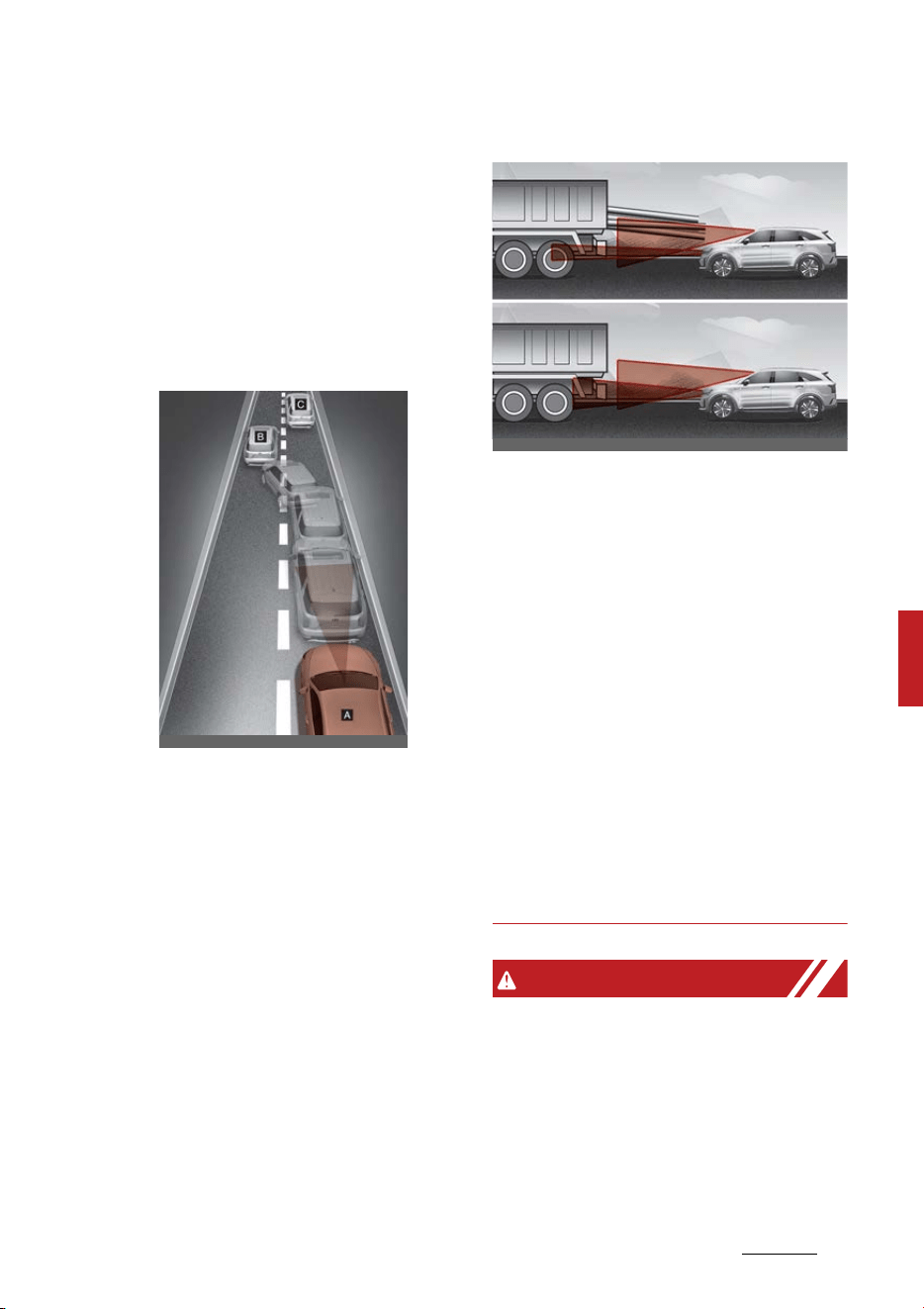
87
6
6
Driving your vehicle Forward Collision-Avoidance Assist (FCA)
(Sensor fusion)
ance Assist may not immediately
detect the vehicle when the vehi
-
cle changes lanes abruptly. In this
case, you must maintain a safe
braking distance, and if neces
-
sary, steer your vehicle and
depress the brake pedal to reduce
your driving speed in order to
maintain a safe distance.
[A]: Your vehicle
[B]: Lane changing vehicle
[C]: Same lane vehicle
When a vehicle [B] in front of you
merges out of the lane, Forward
Collision-Avoidance Assist may
not immediately detect the vehi
-
cle [C] that is now in front of you.
In this case, you must maintain a
safe braking distance, and if nec
-
essary, steer your vehicle and
depress the brake pedal to reduce
your driving speed in order to
maintain a safe distance.
䳜 Detecting vehicle
If the vehicle in front of you has
cargo that extends rearward from
the cab, or when the vehicle in
front of you has higher ground
clearance, additional special
attention is required. Forward
Collision-Avoidance Assist may
not be able to detect the cargo
extending from the vehicle. In
these instances, you must main
-
tain a safe braking distance from
the rearmost object, and if neces
-
sary, steer your vehicle and
depress the brake pedal to reduce
your driving speed in order to
maintain distance.
WARNING
䳜 When you are towing a trailer or
another vehicle, we recommend
that Forward Collision-Avoidance
Assist is turned off due to safety
reasons.
䳜 Forward Collision-Avoidance
Assist may operate if objects that
OADAS033SDY
OMQ4H050038

Driving your vehicle
886
Forward Collision-Avoidance Assist (FCA) (Sensor
fusion)
are similar in shape or character
-
istics to vehicles, pedestrians and
cyclists are detected.
䳜 Forward Collision-Avoidance
Assist does not operate on bicy
-
cles, motorcycles, or smaller
wheeled objects, such as luggage
bags, shopping carts, or strollers
that are dragged by a pedestrian
or a cyclist.
䳜 Forward Collision-Avoidance
Assist may not operate normally
if interfered by strong electro
-
magnetic waves.
䳜 Forward Collision-Avoidance
Assist may not operate for
approximately 15 seconds after
the vehicle is started, or the front
view camera is initialized.
This device complies with Part 15
of the FCC rules.
Operation is subject to the following
three conditions:
1. This device may not cause harm
-
ful interference.
2. This device must accept any
interference received, including
interference that may cause
undesired operation.
3. Changes or modifications not
expressly approved by the party
responsible for compliance could
void the user's authority to oper
-
ate the device.
Radio frequency radiation exposure
information:
This equipment complies with FCC
radiation exposure limits set forth
for an uncontrolled environment.
This equipment should be installed
and operated with minimum dis
-
tance of 8 in (20 cm) between the
radiator (antenna) and your body.
This transmitter must not be colo
-
cated or operating in conjunction
with any other antenna or trans
-
mitter.
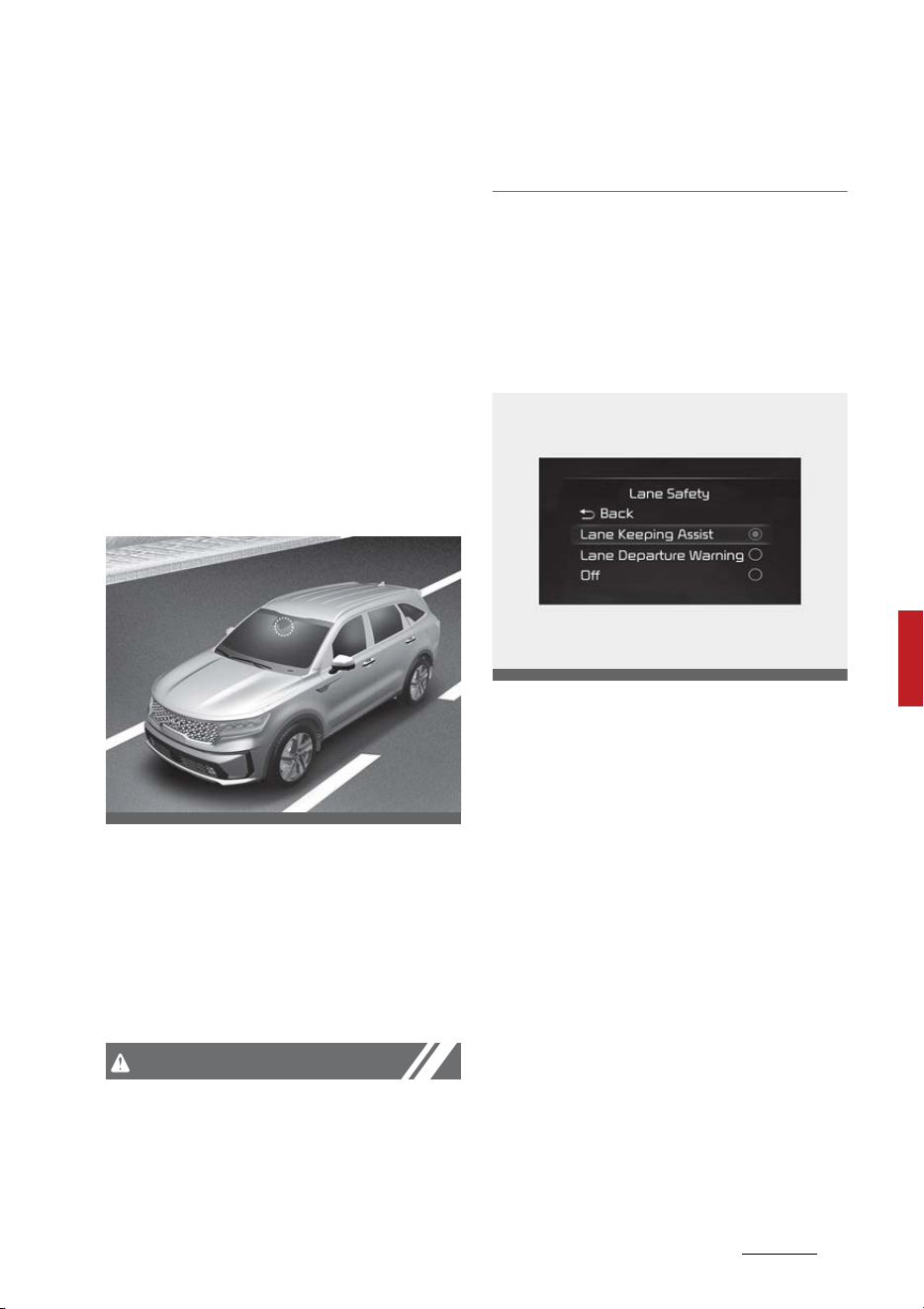
89
6
6
Driving your vehicle Lane Keeping Assist (LKA)
Lane Keeping Assist (LKA)
Lane Keeping Assist is designed to
help detect lane markings (or road
edges) while driving over a certain
speed. The function will warn the
driver if the vehicle leaves the lane
without using the turn signal, or will
automatically assist the driver's
steering to help prevent the vehicle
from departing the lane.
Detecting sensor
Front view camera
The front view camera is used as a
detecting sensor to detect lane
markings (or road edges).
Refer to the picture above for the
detailed location of the detecting
sensor.
CAUTION
For more details on the precautions
of the front view camera, refer to
"Forward Collision-Avoidance Assist
(FCA) (Sensor fusion) (if equipped)"
on page 6-73.
Lane Keeping Assist Settings
Setting
Lane Safety
With the ENGINE START/STOP but
-
ton in the ON position, select or
deselect 'Driver Assistance → Lane
Safety' from the Settings menu to
set whether or not to use each
function.
䳜 If 'Lane Keeping Assist' is
selected, the function will auto
-
matically assist the driver's steer
-
ing when lane departure is
detected to help prevent the vehi
-
cle from moving out of its lane.
䳜 If 'Lane Departure Warning' is
selected, the function will warn
the driver with an audible warning
and steering wheel vibration
when lane departure is detected.
The driver must steer the vehicle.
OMQ4H051009
OMQ4AH050345
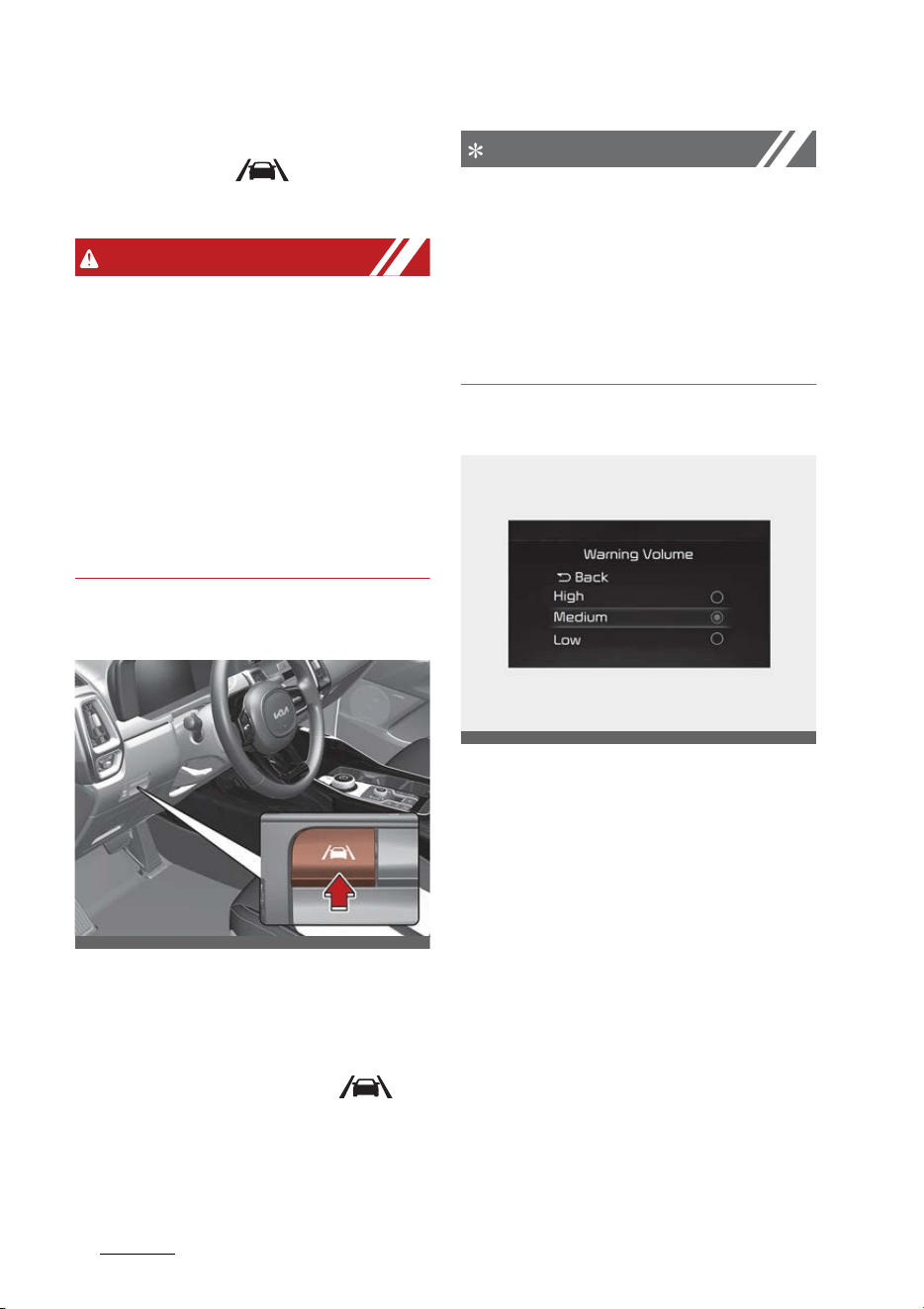
Driving your vehicle
906
Lane Keeping Assist (LKA)
䳜 If 'Off' is selected, the function will
turn off. The ( ) indicator
light will turn off on the cluster.
WARNING
䳜 If 'Lane Departure Warning' is
selected, steering is not assisted.
䳜 Lane Keeping Assist does not con
-
trol the steering wheel when the
vehicle is driven in the middle of
the lane.
䳜 The driver should always be
aware of the surroundings and
steer the vehicle if 'Off' is
selected.
Turning On/Off
With the ENGINE START/STOP but
-
ton in the ON position, press the
Lane Safety button located on the
instrument panel to turn on Lane
Keeping Assist. The white ( )
indicator light will illuminate on the
cluster.
NOTICE
䳜 If the engine is restarted, Lane
Keeping Assist will maintain the
last setting.
䳜 When Lane Keeping Assist is
turned off with the Lane Safety
button, Lane Safety settings will
turn off.
Warning Volume
With the ENGINE START/STOP but
-
ton in the ON position, select 'Driver
Assistance → Warning Volume' from
the Settings menu to change the
Warning Volume to 'High', 'Medium',
'Low' or 'Off' for Lane Keeping
Assist.
However, even if 'Off' is selected,
Lane Keeping Assist Warning Vol
-
ume will not turn off but the volume
will sound as 'Low'.
If you change the Warning Volume,
the Warning Volume of other Driver
Assistance functions may be
changed.
OMQ4051081
OMQ4041606
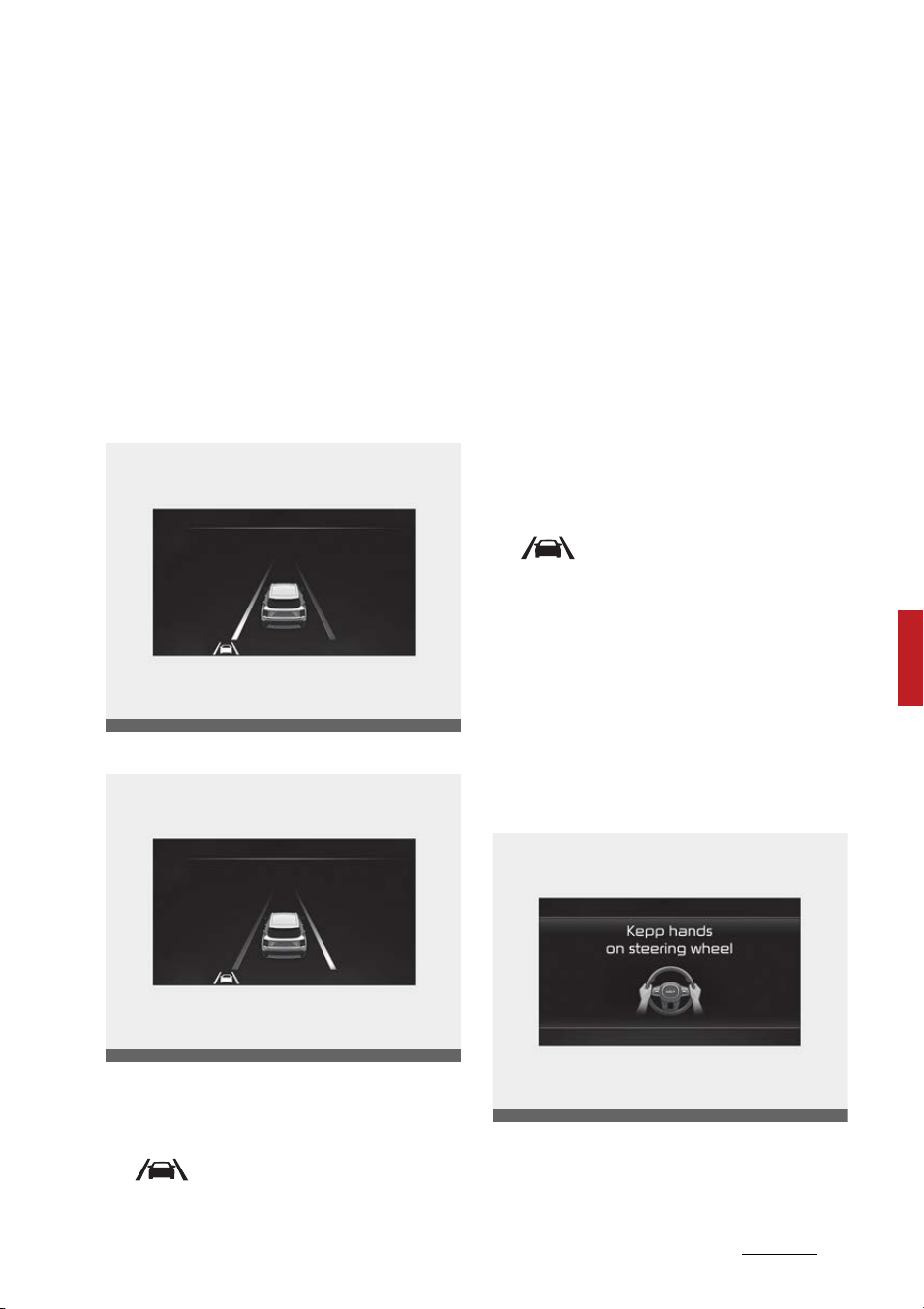
91
6
6
Driving your vehicle Lane Keeping Assist (LKA)
Lane Keeping Assist Operation
Warning and control
Lane Keeping Assist will warn and
control the vehicle with Lane Depar
-
ture Warning and Lane Keeping
Assist.
Lane Departure Warning
Left
Right
䳜 To warn the driver that the vehi
-
cle is departing from the pro
-
jected lane in front, the green
( ) indicator light will blink on
the cluster, the lane line will blink
on the cluster depending on which
direction the vehicle is veering,
and an audible warning will sound.
Also, the steering wheel will
vibrate.
䳜 The function will operate when
your vehicle speed is between
approximately 40 ~ 120 mph (60 ~
200 km/h).
Lane Keeping Assist
䳜 To warn the driver that the vehi
-
cle is departing from the pro
-
jected lane in front, the green
( ) indicator light will blink on
the cluster, and the steering
wheel will make adjustments to
keep vehicle inside the lane.
䳜 The function will operate when
your vehicle speed is between
approximately 40 ~ 120 mph (60 ~
200 km/h).
Hands-off warning
If the driver takes their hands off
the steering wheel for several sec
-
onds, the 'Keep hands on the steer
-
OMQ4050085
OMQ4050086
OMQ4051155L
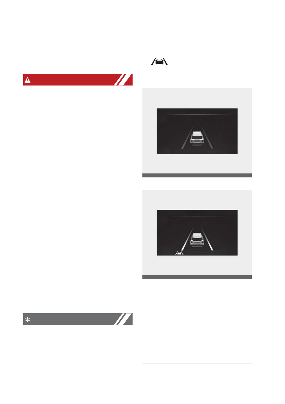
Driving your vehicle
926
Lane Keeping Assist (LKA)
ing wheel' warning message will
appear on the cluster, and an audi
-
ble warning will sound in stages.
WARNING
䳜 The steering wheel may not be
assisted if the steering wheel is
held very tight or the steering
wheel is steered over a certain
degree.
䳜 Lane Keeping Assist does not
operate at all times. It is the
responsibility of the driver to
safely steer the vehicle and to
maintain the vehicle in its lane.
䳜 The hands䳍off warning message
may appear late depending on
road conditions. Always have your
hands on the steering wheel while
driving.
䳜 If the steering wheel is held very
lightly, the hands䳍off warning
message may appear because the
function may not recognize that
the driver has their hands on the
steering wheel.
䳜 If you attach objects to the steer
-
ing wheel, the hands-off warning
may not work properly.
NOTICE
䳜 For more details on the setting
cluster, refer to "Instrument clus
-
ter" on page 5-80.
䳜 When lane markings (or road
edges) are detected, the lane lines
on the cluster will change from
grey to white and the green
( ) indicator light will illumi
-
nate.
Lane undetected
Lane detected
䳜 Even though the steering is
assisted by Lane Keeping Assist,
the driver may control the steer
-
ing wheel.
䳜 The steering wheel may feel
heavier or lighter when the steer
-
ing wheel is assisted by Lane
Keeping Assist than when it is
not.
OMQ4050296L
OMQ4050084
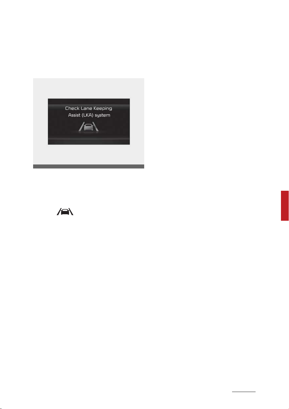
93
6
6
Driving your vehicle Lane Keeping Assist (LKA)
Lane Keeping Assist Malfunction
and Limitations
Lane Keeping Assist malfunction
When Lane Keeping Assist is not
working properly, the 'Check Lane
Keeping Assist (LKA) system' warn
-
ing message will appear and the
yellow ( ) indicator light will illu
-
minate on the cluster. If this occurs,
have the function be inspected by
an authorized Kia dealer.
Limitations of Lane Keeping Assist
Lane Keeping Assist may not oper
-
ate normally or may operate unex
-
pectedly under the following
circumstances:
䳜 The lane is contaminated or diffi
-
cult to distinguish because,
- The lane markings (or road
edge) is covered with rain,
snow, dirt, oil, etc.
- The color of the lane marking
(or road edge) is not distin
-
guishable from the road
- There are markings (or road
edges) on the road near the
lane or the markings (or road
edges) on the road looks similar
to the lane markings (or road
edges)
- The lane marking (or road edge)
is indistinct or damaged
- The shadow is on the lane
marking (or road edge) by a
median strip, trees, guardrail,
noise barriers, etc.
䳜 There are more than two lane
markings (or road edges) on the
road
䳜 The lane number increases or
decreases, or the lane markings
are crossing
䳜 The lane markings (or road edges)
are complicated or a structure
substitutes for the lines, such as a
construction area
䳜 There are road markings, such as
zigzag lanes, crosswalk markings
and road signs
䳜 The lane suddenly disappears,
such as at the intersection
䳜 The lane (or road width) is very
wide or narrow
䳜 There is a road edge without a
lane
䳜 There is a boundary structure in
the roadway, such as a tollgate,
sidewalk, curb, etc.
䳜 The distance to the front vehicle
is extremely short or the vehicle
in front is covering the lane mark
-
ing (or road edge)
OMQ4050214L

Driving your vehicle
946
Lane Keeping Assist (LKA)
䳜 The vehicle is driving to the bus
lane, or driving at the left or right
side of the bus lane
CAUTION
For more details on the limitations
of the front view camera, refer to
"Forward Collision-Avoidance Assist
(FCA) (Sensor fusion) (if equipped)"
on page 6-73.
NOTICE
Take the following precautions
when using Lane Keeping Assist:
䳜 The driver should hold the
responsibility to safely drive and
control the vehicle. Do not solely
rely on the function and drive
dangerously.
䳜 The operation of Lane Keeping
Assist can be canceled or not
work properly depending on road
conditions and surroundings.
Always be cautious while driving.
䳜 Refer to "Limitations" if the lane is
not detected properly.
䳜 When you are towing a trailer or
another vehicle, we recommend
that Lane Keeping Assist is turned
off due to safety reasons.
䳜 If the vehicle is driven at high
speed, the steering wheel will not
be controlled. The driver must
always follow the speed limit
when using the function.
䳜 If any other function's warning
message is displayed or audible
warning is generated, Lane Keep
-
ing Assist warning message may
not be displayed and audible
warning may not be generated.
䳜 You may not hear the warning
sound of Lane Keeping Assist if
the surrounding is noisy.
䳜 If you attach objects to the steer
-
ing wheel, steering may not be
assisted properly.
䳜 Lane Keeping Assist may not
operate for approximately 15
seconds after the vehicle is
started, or the Front view camera
is initialized.
䳜 Lane Keeping Assist will not oper
-
ate when:
- The turn signal or hazard war
-
ing flasher is turned on
- The vehicle is not driven in the
center of the lane when the
function is turned on or right
after changing a lane
- ESC (Electronic Stability Con
-
trol) or VSM (Vehicle Stability
Management) is activated
- The vehicle is driven on a sharp
curve
- Vehicle speed is below 34 mph
(55 km/h) or above 130 mph
(210 km/h)
- The vehicle makes sharp lane
changes
- The vehicle brakes suddenly
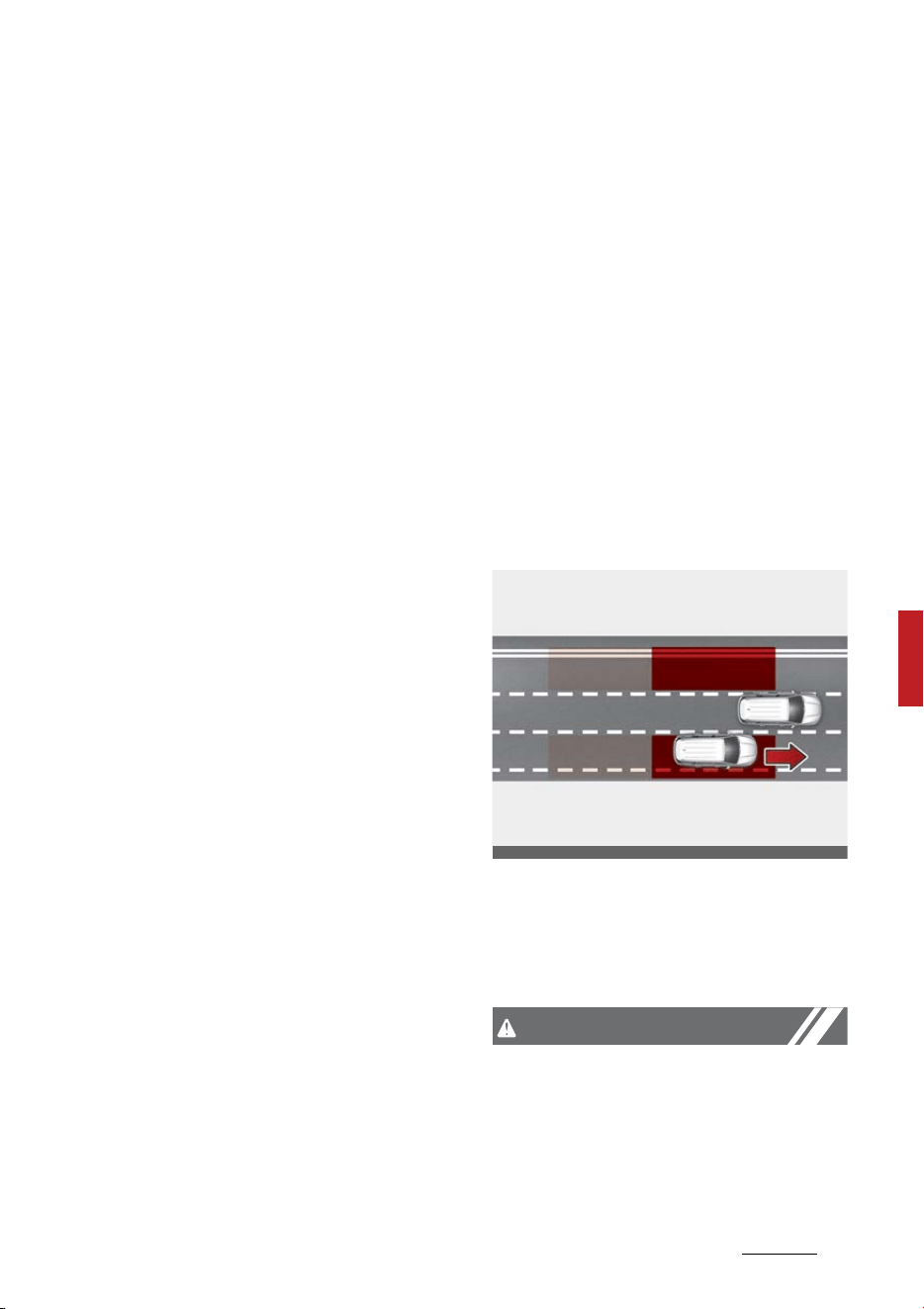
95
6
6
Driving your vehicle Blind-Spot Collision-Avoidance Assist (BCA)
This device complies with Part 15
of the FCC rules.
Operation is subject to the following
two conditions:
1. This device may not cause harm
-
ful interference.
2. This device must accept any
interference received, including
interference that may cause
undesired operation.
Blind-Spot Collision-Avoidance
Assist (BCA) (if equipped)
Blind-Spot Collision-Avoidance
Assist is designed to help detect and
monitor approaching vehicles in the
driver's blind spot area and warn the
driver of a possible collision with a
warning message and audible warn
-
ing.
In addition, if there is a risk of colli
-
sion when changing lanes or driving
forward out of a parking space, the
function will help avoid collision by
applying the brake.
Blind-Spot Collision-Avoidance
Assist will help detect and inform
the driver that a vehicle is in the
blind spot.
CAUTION
The detecting range may vary
depending on the speed of your
vehicle. However, even if there is a
vehicle in the blind spot, the function
OMQ4AH050331
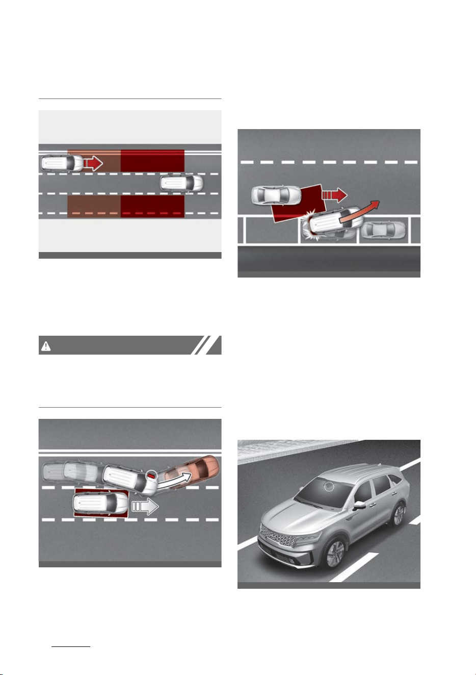
Driving your vehicle
966
Blind-Spot Collision-Avoidance Assist (BCA)
may not warn you when you pass
by at high speeds.
Blind-Spot Collision Assist help
detect and informs the driver that a
vehicle is approaching at high speed
from the blind spot area.
CAUTION
Warning Timing may vary depend
-
ing on the speed of the vehicle
approaching at high speed.
When changing lanes by detecting
the lane ahead, if the function
judges that there is a collision risk
with an approaching vehicle in the
blind spot, the function will help
avoid collision by applying the dif
-
ferential brake.
When you are driving forward out of
a parking space, if Blind-Spot Colli
-
sion-Avoidance Assist judges that
there is a collision risk with an
approaching vehicle in the blind spot,
the function will help avoid collision
by applying the brake.
Detecting sensor
Front view camera
OMQ4050092
OMQ4AH051093
OMQ4050245
OMQ4H051009
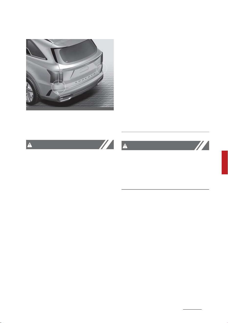
97
6
6
Driving your vehicle Blind-Spot Collision-Avoidance Assist (BCA)
Rear corner radar
Refer to the picture above for the
detailed location of the detecting
sensors.
CAUTION
Take the following precautions to
maintain optimal performance of
the detecting sensor:
䳜 Never disassemble the rear corner
radar or radar assembly, or apply
any impact on it.
䳜 If there is impact on the rear cor
-
ner radar or near the radar, even
though the warning message
does not appear on the cluster,
Blind-Spot Collision-Avoidance
Assist may not operate properly.
Have the function be inspected by
an authorized Kia dealer.
䳜 If the rear corner radars have
been replaced or repaired, Have
the vehicle be inspected by an
authorized Kia dealer.
䳜 Use only genuine Kia parts to
repair the rear bumper where the
rear corner radar is located.
䳜 Do not apply license plate frame
or objects, such as a bumper
sticker, film or a bumper guard
near the rear corner radar.
䳜 The function may not work prop
-
erly if the bumper has been
replaced, or the surroundings of
the rear corner radar has been
damaged or paint has been
applied.
䳜 If a trailer, carrier, etc. is installed,
it may adversely affect the per
-
formance of the rear corner radar
or the function may not operate.
CAUTION
For more details on the precautions
of the front view camera, refer to
"Forward Collision-Avoidance Assist
(FCA) (Sensor fusion) (if equipped)"
on page 6-73.
OMQ4AH051330
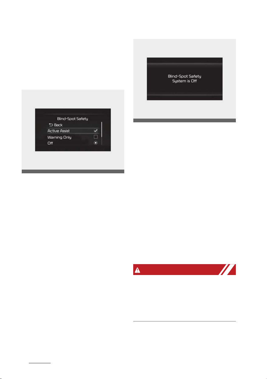
Driving your vehicle
986
Blind-Spot Collision-Avoidance Assist (BCA)
Blind-Spot Collision-Avoidance
Assist Settings
Setting
Blind-Spot Safety
With the ENGINE START/STOP but
-
ton in the ON position, select or
deselect 'Driver Assistance → Blind-
Spot Safety' from the Settings
menu to set whether or not to use
each function.
䳜 If 'Active Assist' is selected, the
function will warn the driver with
a warning message, an audible
warning, steering wheel vibration
and braking assist will be applied
depending on the collision risk lev
-
els.
䳜 If 'Warning Only' is selected, the
function will warn the driver with
a warning message, an audible
warning and steering wheel vibra
-
tion depending on the collision risk
levels. Braking will not be assisted.
䳜 If 'Off' is selected, the function will
turn off.
When the engine is restarted with
the function off, the 'Blind-Spot
Safety System is Off' message will
appear on the cluster.
If you change the setting from 'Off'
to 'Active Assist' or 'Warning Only',
the warning light on the side view
mirror will blink for approximately 3
seconds.
In addition, if the engine is turned
on, when the function is set to
'Active Assist' or 'Warning Only', the
warning light on the side view mir
-
ror will blink for approximately 3
seconds.
WARNING
䳜 'If 'Warning Only' is selected,
braking is not assisted.
䳜 If 'Off' is selected, the driver
should always be aware of the
surroundings and drive safely.
OMQ4A050340
OMQ4050293L
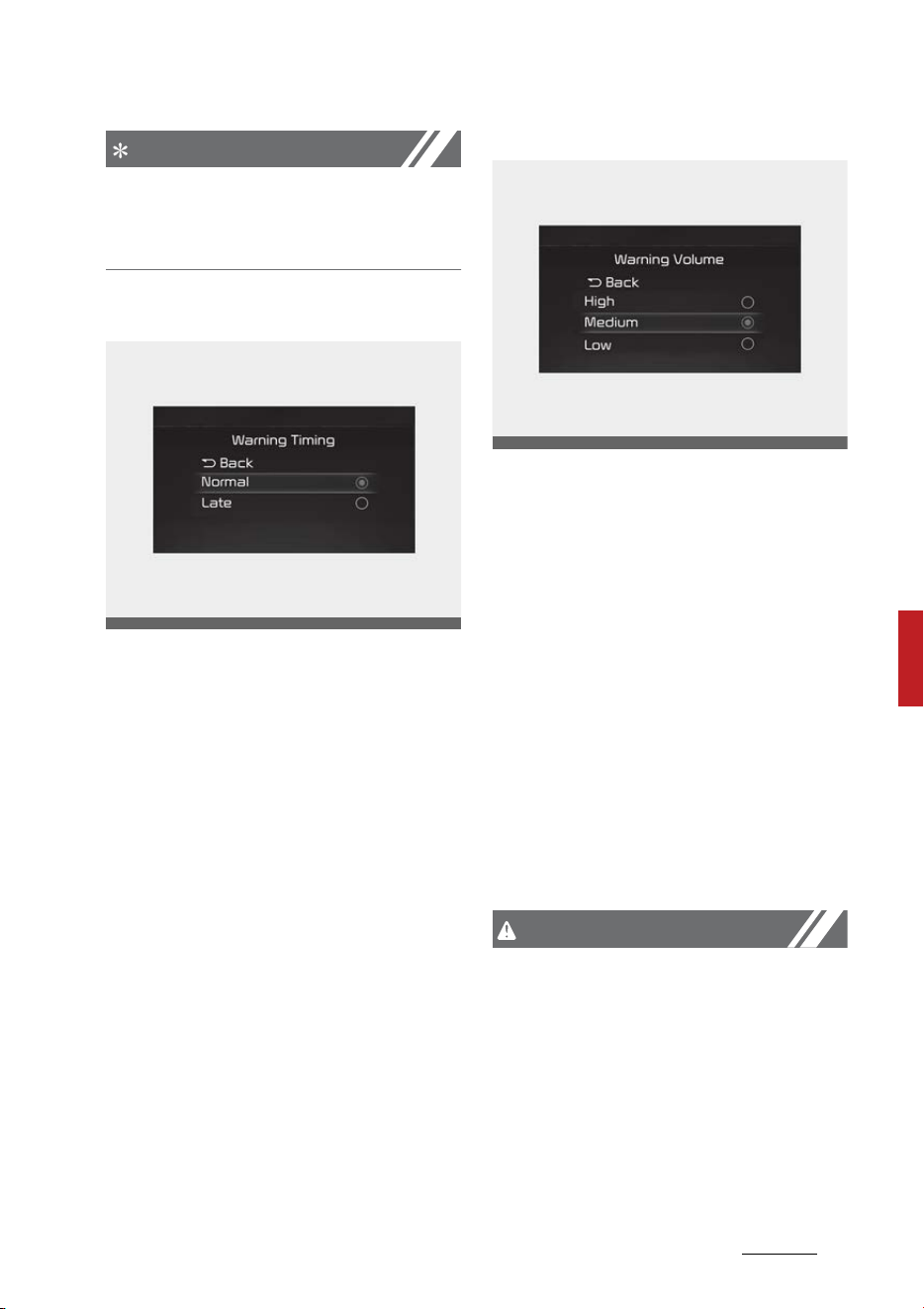
99
6
6
Driving your vehicle Blind-Spot Collision-Avoidance Assist (BCA)
NOTICE
If the engine is restarted, Blind-Spot
Collision-Avoidance Assist will main
-
tain the last setting.
Warning Timing
With the ENGINE START/STOP but
-
ton in the ON position, select 'Driver
Assistance → Warning Timing' from
the Settings menu to change the
initial warning activation time for
Blind-Spot Collision-Avoidance
Assist.
When the vehicle is first delivered,
Warning Timing is set to 'Normal. If
you change the Warning Timing, the
warning time of other Driver Assis
-
tance systems may change.
Warning Volume
With the ENGINE START/STOP but
-
ton in the ON position, select 'Driver
Assistance → Warning Volume' from
the Settings menu to change the
Warning Volume to 'High', 'Medium',
'Low' or 'Off' for Blind-Spot Colli
-
sion-Avoidance Assist.
However, when Warning Volume is
turned off, the steering wheel
vibration function will turn on if it
was turned off.
If you change the Warning Volume,
the Warning Volume of other Driver
Assistance systems may change.
CAUTION
䳜 The setting of the Warning Timing
and Warning Volume applies to all
functions of Blind-Spot Collision-
Avoidance Assist.
䳜 Even though 'Normal' is selected
for Warning Timing, if the vehicles
approaches at high speed, the ini
-
tial warning activation time may
seem late.
OMQ4AH050334
OMQ4041606
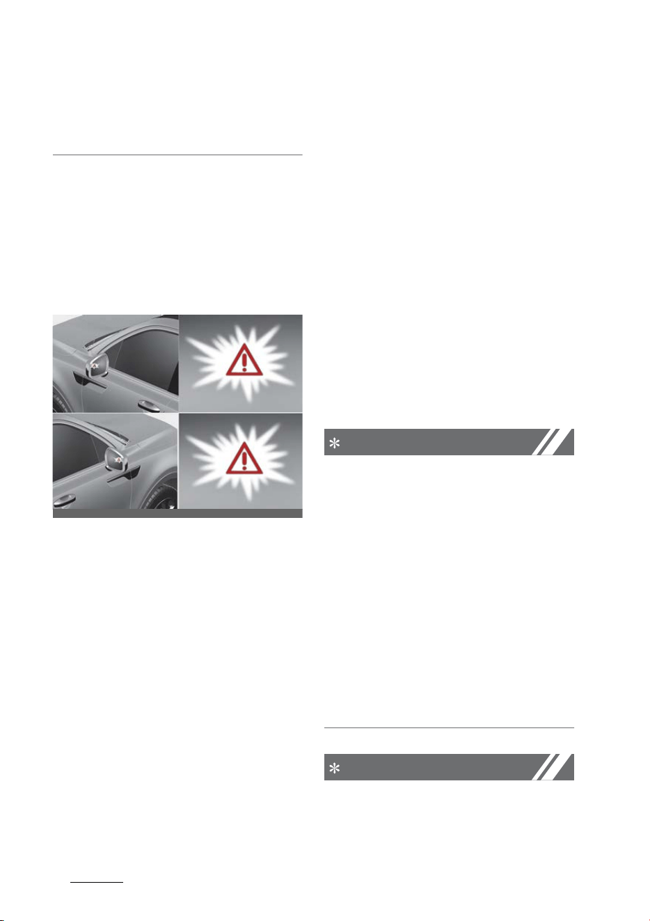
Driving your vehicle
1006
Blind-Spot Collision-Avoidance Assist (BCA)
䳜 Select 'Late' for Warning Timing
when traffic is light and when
driving speed is slow.
Blind-Spot Collision-Avoidance
Assist Operation
Warning and control
Vehicle detection
䳜 To warn the driver a vehicle is
detected, the warning light on the
side view mirror and head-up dis
-
play (if equipped) will illuminate.
䳜 The function will operate when
your vehicle speed is above 12
mph (20 km/h) and the speed of
the vehicle in the blind spot area is
above 7 mph (10 km/h).
Collision Warning
䳜 Collision Warning will operate
when the turn signal is turned on
in the direction of the detected
vehicle.
䳜 If 'Warning Only' is selected from
the Settings menu, the collision
warning will operate when your
vehicle approaches the lane the
blind spot vehicle is detected.
䳜 To warn the driver of a collision,
the warning light on the side view
mirror and head-up display (if
equipped) will blink. At the same
time, an audible warning will
sound and the steering wheel will
vibrate.
䳜 When the turn signal is turned
off, the collision warning will be
canceled and the function will
return to vehicle detection state.
NOTICE
䳜 The detecting range of the rear
corner radar is determined by a
standard road width, therefore,
on a narrow road, the function
may detect other vehicles in the
next lane and warn you. In con
-
trast, on a wide road, the function
may not be able to detect a vehi
-
cle driving in the next lane and
may not warn you.
䳜 When the hazard warning flasher
is on, the collision warning by the
turn signal will not operate.
NOTICE
If the driver's seat is on the left side,
the collision warning may occur
when you turn left. Maintain a
OMQ4050098
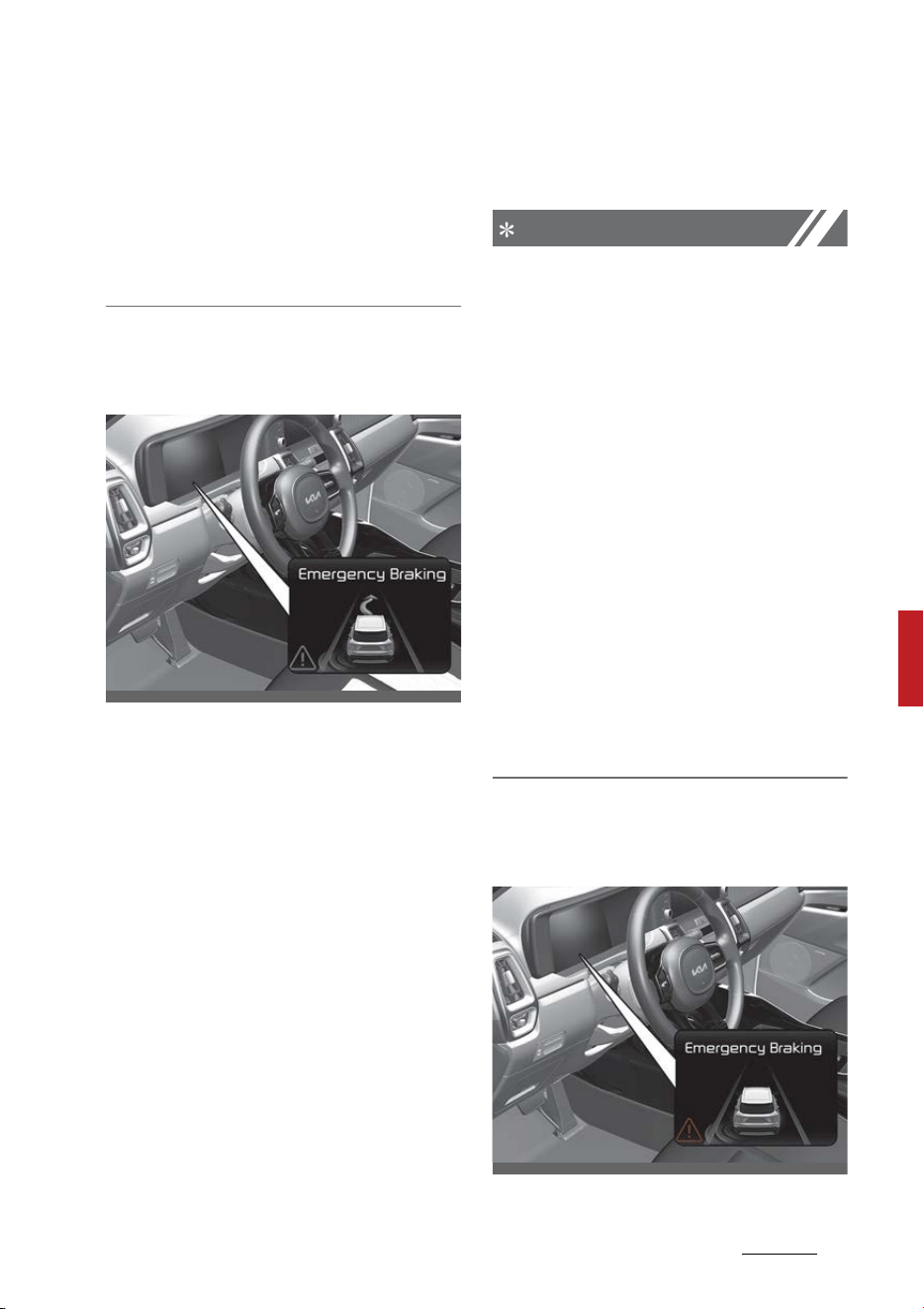
101
6
6
Driving your vehicle Blind-Spot Collision-Avoidance Assist (BCA)
proper distance with the vehicles in
the left lane. If the driver's seat is on
the right side, the collision warning
may occur when you turn right.
Maintain a proper distance with the
vehicles in the right lane.
Collision-Avoidance Assist (while
driving)
䳜 To warn the driver of a collision,
the warning light on the side view
mirror will blink and a warning
message will appear on the clus
-
ter. At the same time, an audible
warning will sound, warning light
on the head-up display (if
equipped) will blink and the steer
-
ing wheel will vibrate.
䳜 Blind-Spot Collision-Avoidance
Assist will operate when your
vehicle speed is between 40 ~ 120
mph (60 ~ 200 km/h) and both
lane markings of the driving lane
are detected.
䳜 Emergency braking will be
assisted to help prevent collision
with the vehicle in the blind spot
area.
NOTICE
䳜 Collision-Avoidance Assist will be
canceled under the following cir
-
cumstances:
- Your vehicle enters the next
lane by a certain distance
- Your vehicle is away from the
collision risk
- The steering wheel is sharply
steered
- The brake pedal is depressed
- Forward Collision-Avoidance
Assist is operating
䳜 After Function Operation or
changing lane, you must drive to
the center of the lane. The func
-
tion will not operate if the vehicle
is not driven in the center of the
lane.
Collision-Avoidance Assist (while
departing)
OMQ4051281L
OMQ4051339L
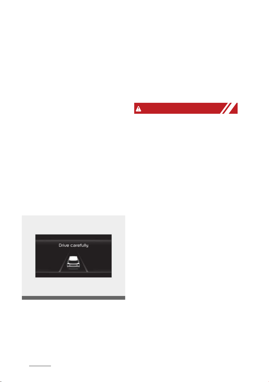
Driving your vehicle
1026
Blind-Spot Collision-Avoidance Assist (BCA)
䳜 To warn the driver of a collision,
the warning light on the side view
mirror will blink and a warning
message will appear on the clus
-
ter. At the same time, an audible
warning will sound, warning light
on the head-up display (if
equipped) will blink and the steer
-
ing wheel will vibrate.
䳜 The system will operate when
your vehicle speed is below (2
mph) 3 km/h and the speed of the
vehicle in the blind spot area is
above (3 mph) 5 km/h.
䳜 Emergency braking will be
assisted to help prevent collision
with the vehicle in the blind spot
area.
Stopping vehicle and ending brake
control
䳜 When the vehicle is stopped due
to emergency braking, the 'Drive
carefully' warning message will
appear on the cluster.
䳜 For your safety, the driver should
depress the brake pedal immedi
-
ately and check the surroundings.
䳜 Brake control will end after the
vehicle is stopped by emergency
braking for approximately 2 sec
-
onds.
WARNING
Take the following precautions
when using Blind-Spot Safety Sys
-
tem:
䳜 For your safety, change the Set
-
tings after parking the vehicle at a
safe location.
䳜 If any other function's warning
message is displayed or audible
warning is generated, Blind-Spot
Collision-Avoidance Assist's warn
-
ing message may not be dis
-
played and audible warning may
not be generated.
䳜 You may not hear the warning
sound of Blind-Spot Collision-
Avoidance Assist if the surround
-
ing is noisy.
䳜 Blind-Spot Collision-Avoidance
Assist may not operate if the
driver applies the brake pedal to
avoid collision.
䳜 When Blind-Spot Collision-Avoid
-
ance Assist is operating, braking
control by the function will auto
-
matically cancel when the driver
excessively depresses the accel
-
erator pedal or sharply steers the
vehicle.
OMQ4040504L
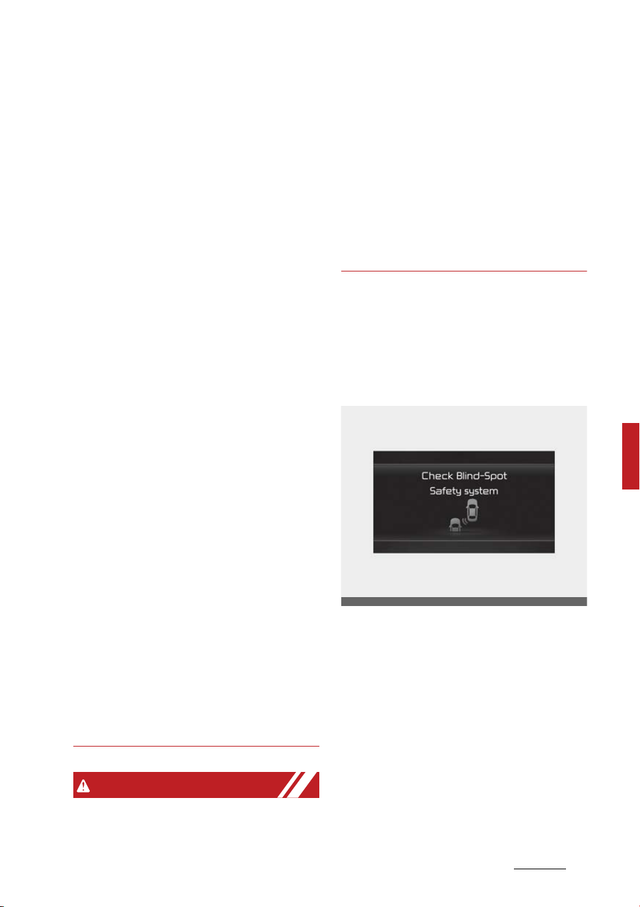
103
6
6
Driving your vehicle Blind-Spot Collision-Avoidance Assist (BCA)
䳜 During Blind-Spot Collision-Avoid
-
ance Assist operation, the vehicle
may stop suddenly injuring pas
-
sengers and shifting loose
objects. Always have the seat belt
on and keep loose objects
secured.
䳜 Even if there is a problem with
Blind-Spot Collision-Avoidance
Assist, the vehicle's basic braking
performance will operate nor
-
mally.
䳜 Blind-Spot Collision-Avoidance
Assist does not operate in all situ
-
ations or cannot avoid all colli
-
sions.
䳜 Blind-Spot Collision-Avoidance
Assist may warn the driver late or
may not warn the driver depend
-
ing on the road and driving condi
-
tions.
䳜 Driver should maintain control of
the vehicle at all times. Do not
depend on Blind-Spot Collision-
Avoidance Assist. Maintain a safe
braking distance, and if neces
-
sary, depress the brake pedal to
reduce driving speed or to stop
the vehicle.
䳜 Never operate Blind-Spot Colli
-
sion-Avoidance Assist on people,
animal, objects, etc. It may cause
serious injury or death.
WARNING
䳜 The brake control may not oper
-
ate properly depending on the
status of ESC (Electronic Stability
Control).
䳜 There will only be a warning
when:
- The ESC (Electronic Stability
Control) warning light is on
-ESC (Electronic Stability Con
-
trol) is engaged in a different
function
Blind-Spot Collision-Avoidance
Assist Malfunction and Limitations
Blind-Spot Collision-Avoidance
Assist malfunction
When Blind-Spot Collision-Avoidance
Assist is not working properly, the
'Check Blind-Spot Safety system'
warning message will appear on the
cluster, and the function will turn
off automatically or the function will
be limited. Have the function be
inspected by an authorized Kia
dealer.
OMQ4050229L
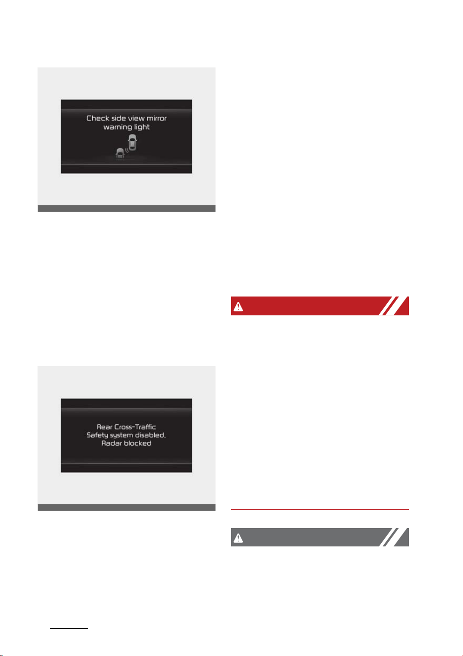
Driving your vehicle
1046
Blind-Spot Collision-Avoidance Assist (BCA)
When the side view mirror warning
light is not working properly, the
'Check side view mirror warning
light' warning message will appear
on the cluster. Have the function be
inspected by an authorized Kia
dealer.
Blind-Spot Collision-Avoidance
Assist disabled
When the rear bumper around the
rear corner radar or sensor is cov
-
ered with foreign material, such as
snow or rain, or installing a trailer or
carrier, it can reduce the detecting
performance and temporarily limit
or disable Blind-Spot Collision-
Avoidance Assist.
If this occurs, the 'Blind-Spot Safety
Function disabled. Radar blocked'
warning message will appear on the
cluster.
The function will operate normally
when such foreign material or
trailer, etc. is removed, and then the
engine is restarted.
If the function does not operate
normally after it is removed, have
the function be inspected by an
authorized Kia dealer.
WARNING
䳜 Even though the warning mes
-
sage does not appear on the clus
-
ter, Blind-Spot Collision-Avoidance
Assist may not properly operate.
䳜 Blind-Spot Collision-Avoidance
Assist may not properly operate
in an area (e.g. open terrain)
where any substance are not
detected right after the engine is
turned on, or when the detecting
sensor is blocked with foreign
material right after the engine is
turned on.
CAUTION
Turn off Blind-Spot Collision-Avoid
-
ance Assist to install a trailer, car
-
rier, etc., or remove the trailer,
OMQ4050291L
OMQ4050292L

105
6
6
Driving your vehicle Blind-Spot Collision-Avoidance Assist (BCA)
carrier, etc. to use Blind-Spot Colli
-
sion-Avoidance Assist.
Limitations of Blind-Spot Collision-
Avoidance Assist
Blind-Spot Collision-Avoidance
Assist system may not operate nor
-
mally, or the function may operate
unexpectedly under the following
circumstances:
䳜 There is inclement weather, such
as heavy snow, heavy rain, etc.
䳜 The rear corner radar is covered
with snow, rain, dirt, etc.
䳜 The temperature around the rear
corner radar is high or low
䳜 Driving on a highway (or motor
-
way) ramp
䳜 The road pavement (or the
peripheral ground) abnormally
contains metallic components (i.e.
possibly due to subway construc
-
tion).
䳜 There is a fixed object near the
vehicle, such as sound barriers,
guardrails, central dividers, entry
barriers, street lamps, signs, tun
-
nels, walls, etc. (including double
structures)
䳜 Driving in large areas where there
are few vehicles or structures (i.e.
desert, meadow, suburb, etc.)
䳜 Driving through a narrow road
where trees or grass are over
-
grown
䳜 Driving in large areas where there
are few vehicles or structures (i.e.
desert, meadow, suburb, etc.)
䳜 Driving on a wet road surface,
such as a puddle on the road
䳜 The other vehicle drives very close
behind your vehicle, or the other
vehicle passes by your vehicle in
close proximity
䳜 The speed of the other vehicle is
very fast that it passes by your
vehicle in a short time
䳜 Your vehicle passes by the other
vehicle
䳜 Your vehicle changes lane
䳜 Your vehicle has started at the
same time as the vehicle next to
you and has accelerated
䳜 The vehicle in the next lane moves
two lanes away from you, or
when the vehicle two lanes away
moves to the next lane from you
䳜 A trailer or carrier is installed
around the rear corner radar
䳜 The bumper around the rear cor
-
ner radar is covered with objects,
such as a bumper sticker, bumper
guard, bike rack, etc.
䳜 The bumper around the rear cor
-
ner radar is impacted, damaged
or the radar is out of position
䳜 Your vehicle height is low or high
due to heavy loads, abnormal tire
pressure, etc.
Blind-Spot Collision-Avoidance
Assist may not operate normally, or
the function may operate unex
-
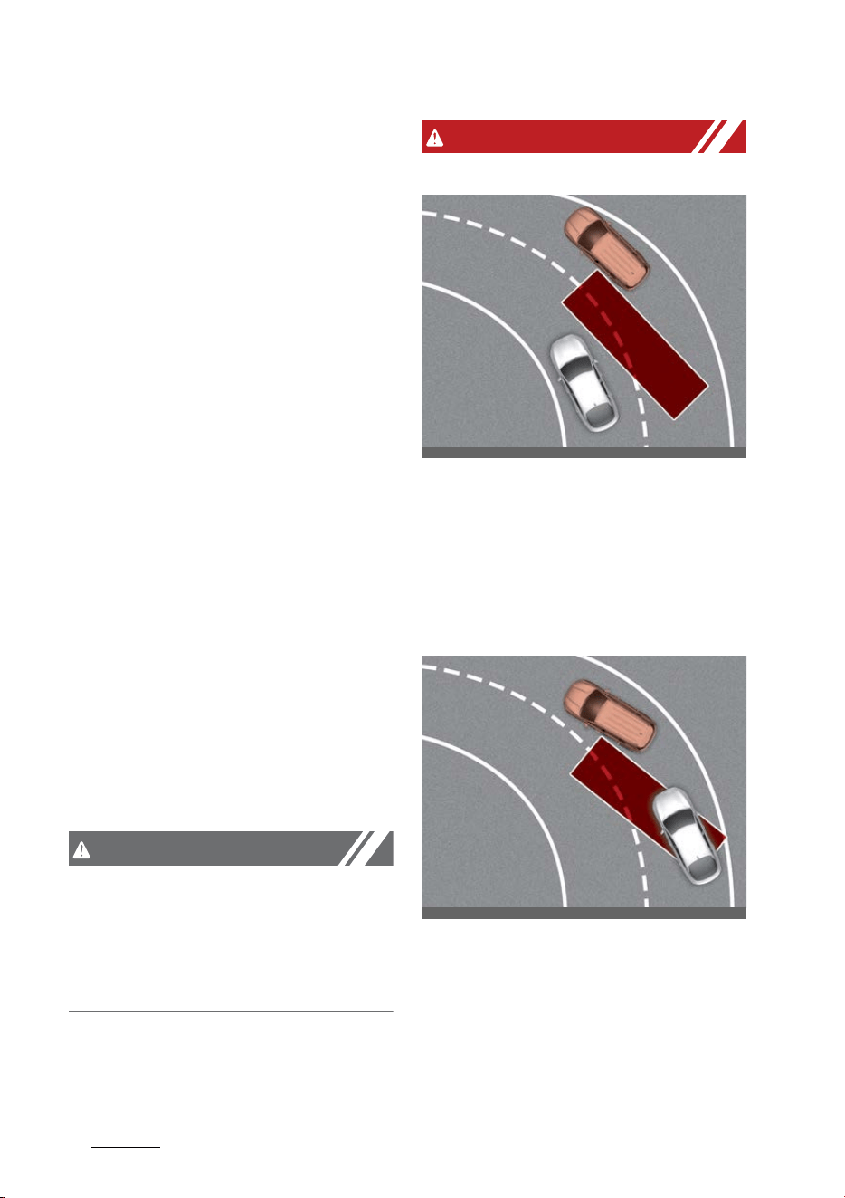
Driving your vehicle
1066
Blind-Spot Collision-Avoidance Assist (BCA)
pectedly when the following objects
are detected:
䳜 A motorcycle or bicycle is
detected
䳜 A vehicle such as a flat trailer is
detected
䳜 A big vehicle such as a bus or
truck is detected
䳜 A moving obstacle such as a
pedestrian, animal, shopping cart
or a baby stroller is detected
䳜 A vehicle with low height such as a
sports car is detected
Braking control may not work,
driver's attention is required in the
following circumstances:
䳜 The vehicle severely vibrates
while driving over a bumpy road,
uneven road or concrete patch
䳜 Driving on a slippery surface due
to snow, water puddle, ice, etc.
䳜 The tire pressure is low or a tire is
damaged
䳜 The brake is reworked
䳜 The vehicle makes abrupt lane
changes
CAUTION
For more details on the limitations
of the front view camera, refer to
"Forward Collision-Avoidance Assist
(FCA) (Front view camera only) (if
equipped)" on page 6-60.
WARNING
䳜 Driving on a curved road
Blind-Spot Collision-Avoidance
Assist may not operate properly
when driving on a curved road.
The function may not detect the
vehicle in the next lane.
Always pay attention to road and
driving conditions while driving.
Blind-Spot Collision-Avoidance
Assist may not operate properly
when driving on a curved road.
The function may recognize a
vehicle in the same lane.
Always pay attention to road and
driving conditions while driving.
OMQ4050106
OMQ4050107
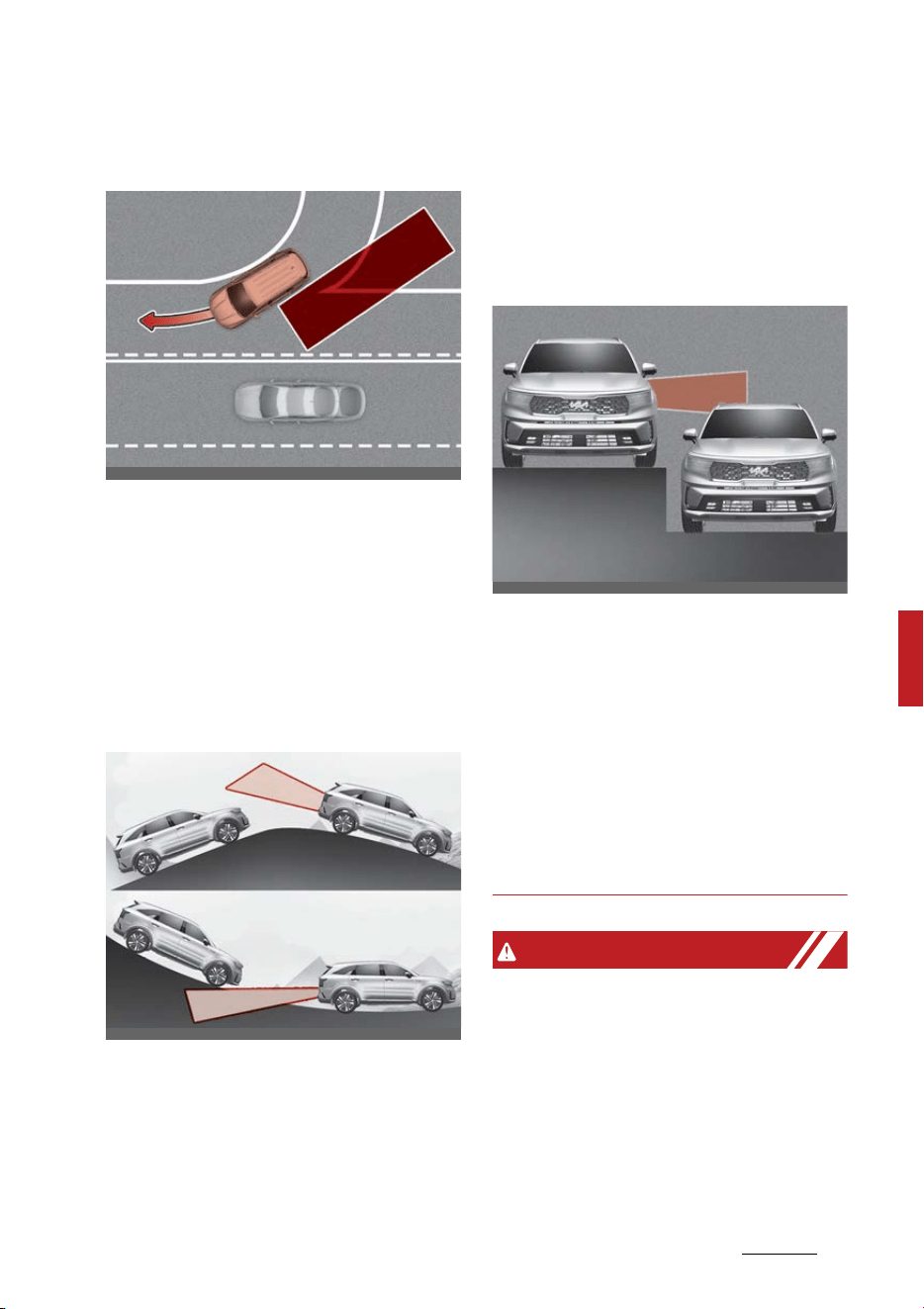
107
6
6
Driving your vehicle Blind-Spot Collision-Avoidance Assist (BCA)
䳜 Driving where the road is merg
-
ing/dividing
Blind-Spot Collision-Avoidance
Assist may not operate properly
when driving where the road
merges or divides. The function
may not detect the vehicle in the
next lane.
Always pay attention to road and
driving conditions while driving.
䳜 Driving on a sloped road
Blind-Spot Collision-Avoidance
Assist may not operate properly
when driving on a slope. The
function may not detect the vehi
-
cle in the next lane or may incor
-
rectly detect the ground or
structure.
Always pay attention to road and
driving conditions while driving.
䳜 Driving where the heights of the
lanes are different
Blind-Spot Collision-Avoidance
Assist may not operate properly
when driving where the heights of
the lanes are different. The func
-
tion may not detect the vehicle on
a road with different lane heights
(underpass joining section, grade
separated intersections, etc.).
Always pay attention to road and
driving conditions while driving.
WARNING
䳜 When you are towing a trailer or
another vehicle, make sure that
you turn off Blind-Spot Collision-
Avoidance Assist.
䳜 Blind-Spot Collision-Avoidance
Assist may not operate normally
if interfered by strong electro
-
magnetic waves.
OMQ4050108
OMQ4H050011
OMQ4051110
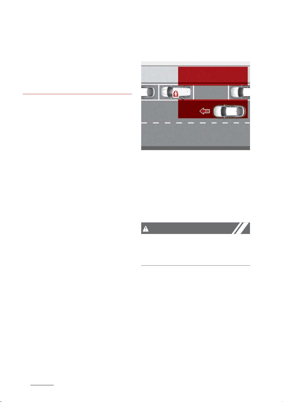
Driving your vehicle
1086
Safe Exit Warning (SEW)
䳜 Blind-Spot Collision-Avoidance
Assist may not operate for
approximately 15 seconds after
the vehicle is started, or the front
view camera or rear corner radars
are initialized.
Safe Exit Warning (SEW) (if
equipped)
After the vehicle stops, when an
approaching vehicle from the rear
area is detected as soon as a pas
-
senger opens a door, Safe Exit
Warning will warn the driver with a
warning message and an audible
warning to help prevent a collision.
CAUTION
Warning Timing may vary depend
-
ing on the speed of the approaching
vehicle.
OMQ4041615
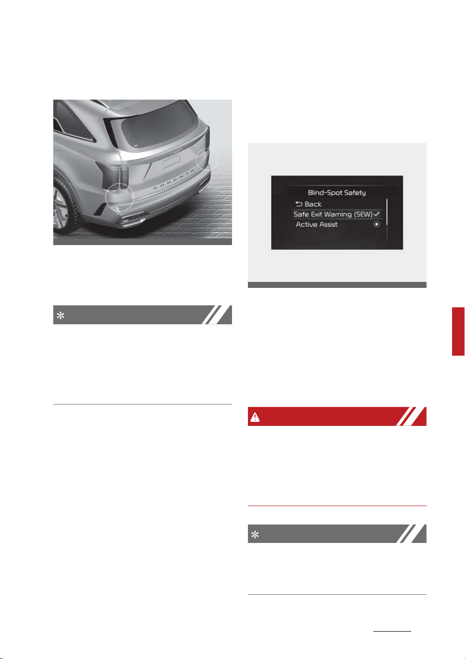
109
6
6
Driving your vehicle Safe Exit Warning (SEW)
Detecting sensor
Rear corner radar
Refer to the picture above for the
detailed location of the detecting
sensor.
NOTICE
For more details on the precautions
of the rear corner radars, refer to
"Blind-Spot Collision-Avoidance
Assist (BCA) (if equipped)" on page
6-95.
Safe Exit Warning Settings
Setting
Safe Exit Warning
With the ENGINE START/STOP but
-
ton in the ON position, select 'Driver
Assistance → Blind-Spot Safety →
Safe Exit Warning from the Settings
menu to turn on Safe Exit Warning
and deselect to turn off the func
-
tion.
WARNING
The driver should always be aware
of unexpected and sudden situa
-
tions from occurring. If Safe Exit
Warning is deselected, the function
cannot assist you.
NOTICE
If the engine is restarted, Safe Exit
Warning will maintain the last set
-
ting.
OMQ4AH051330
OMQ4AH051336L
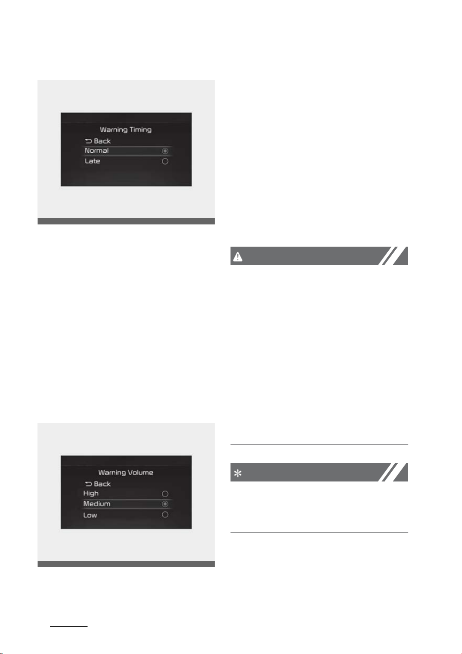
Driving your vehicle
1106
Safe Exit Warning (SEW)
Warning Timing
With the ENGINE START/STOP but
-
ton in the ON position, select 'Driver
Assistance → Warning Timing' from
the Settings menu to change the
initial warning activation time for
Safe Exit Warning.
When the vehicle is first delivered,
Warning Timing is set to 'Normal'. If
you change the Warning Timing, the
warning time of other Driver Assis
-
tance systems may change.
Warning Volume
With the ENGINE START/STOP but
-
ton in the ON position, select 'Driver
Assistance → Warning Volume' from
the Settings menu to change the
Warning Volume to 'High', 'Medium',
'Low' or 'Off' for Safe Exit Warning.
However, when Warning Volume is
turned off, the steering wheel
vibration function will turn on if it
was turned off.
If you change the Warning Volume,
the Warning Volume of other Driver
Assistance systems may change.
CAUTION
䳜 The setting of the Warning Timing
and Warning Volume applies to all
functions of the Safe Exit Warn
-
ing.
䳜 Even though 'Normal' is selected
for Warning Timing, if the vehicles
approaches at high speed from
the rear, the initial warning acti
-
vation time may seem late.
䳜 Select 'Late' for Warning Timing
when traffic is light and when
driving speed is slow.
NOTICE
If the engine is restarted, Warning
Timing and Warning Volume will
maintain the last setting.
OMQ4AH050334
OMQ4041606
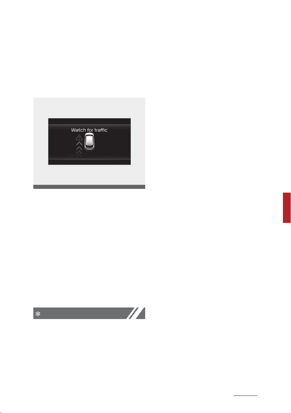
111
6
6
Driving your vehicle Safe Exit Warning (SEW)
Safe Exit Warning Operation
Warning
Collision Warning when exiting
vehicle
䳜 When an approaching vehicle
from the rear is detected at the
moment a door is opened, the
'Watch for traffic' warning mes
-
sage will appear on the cluster,
and an audible warning will sound.
䳜 Safe Exit Warning will warn the
driver when your vehicle speed is
below 2 mph (3 km/h), and the
speed of the approaching vehicle
from the rear is above 3 mph (5
km/h).
NOTICE
Take the following precautions
when using Safe Exit Warning :
䳜 For your safety, change the Set
-
tings after parking the vehicle at a
safe location.
䳜 If any other function's warning
message is displayed or audible
warning is generated, Safe Exit
Warning warning message may
not be displayed and audible
warning may not be generated.
䳜 You may not hear the warning
sound of Safe Exit Warning if the
surrounding is noisy.
䳜 Safe Exit Warning does not oper
-
ate in all situations or cannot pre
-
vent all collisions.
䳜 Safe Exit Warning may warn the
driver late or may not warn the
driver depending on the road and
driving conditions. Always check
vehicle surroundings.
䳜 The driver and passengers are
responsible for accidents that
occurs while exiting the vehicle.
Always check the surroundings
before you exit the vehicle.
䳜 Never deliberately operate Safe
Exit Warning. Doing so may lead
to serious injury or death.
䳜 Safe Exit Warning does not oper
-
ate if there is a problem with
Blind-Spot Collision-Avoidance
Assist. The warning message of
Blind-Spot Collision-Avoidance
Assist will appear when :
- Blind-Spot Collision-Avoidance
Assist sensor or the sensor
surrounding is polluted or cov
-
ered
OMQ4040505L
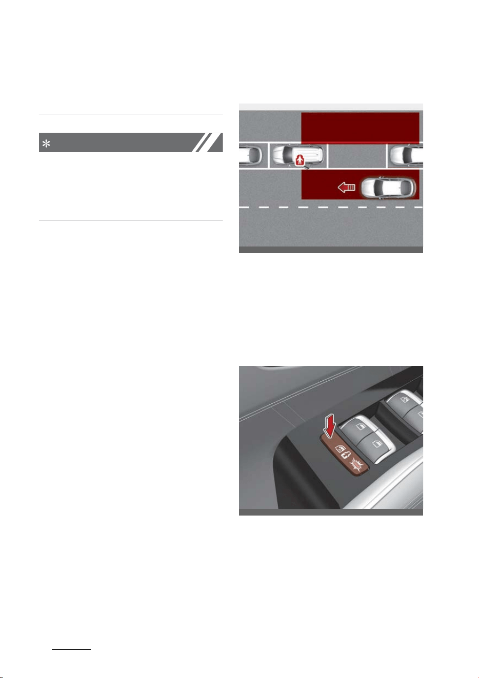
Driving your vehicle
1126
Safe Exit Assist (SEA)
- Blind-Spot Collision-Avoidance
Assist fails to warn passengers
or falsely warn passengers
NOTICE
After the engine is turned off, Safe
Exit Warning operates approxi
-
mately for 3 minutes, but turns off
immediately if the doors are locked.
Safe Exit Assist (SEA) (if
equipped)
After the vehicle stops, when an
approaching vehicle from the rear
area is detected as soon as a pas
-
senger opens a door, Safe Exit
Assist will warn the driver with a
warning message and an audible
warning to help prevent a collision.
In addition, when the electronic child
safety lock button is in the LOCK
position and an approaching vehicle
from the rear area is detected, the
electronic child safety lock button
will not unlock even if the driver
OMQ4041420N
OMQ4AH040008
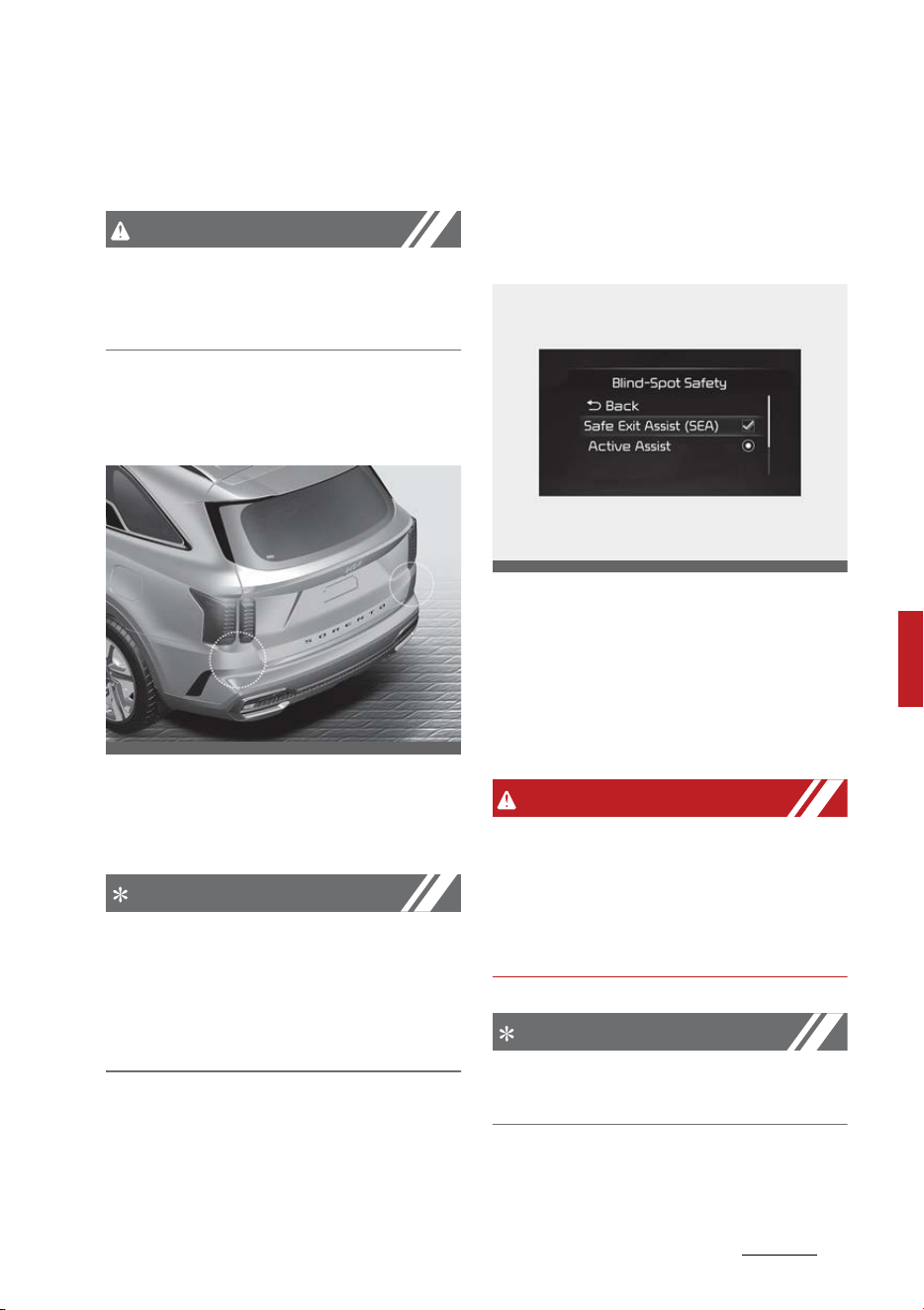
113
6
6
Driving your vehicle Safe Exit Assist (SEA)
presses the button to prevent the
rear doors from opening.
CAUTION
Warning Timing may vary depend
-
ing on the speed of the approaching
vehicle.
Detecting sensor
Rear corner radar
Refer to the picture above for the
detailed location of the detecting
sensor.
NOTICE
For more details on the precautions
of the rear corner radars, refer to
"Blind-Spot Collision-Avoidance
Assist (BCA) (if equipped)" on page
6-95.
Safe Exit Assist Settings
Setting
Safe Exit Assist
With the ENGINE START/STOP but
-
ton in the ON position, select 'Driver
Assistance → Blind-Spot Safety →
Safe Exit Assist' from the Settings
menu to turn on Safe Exit Assist and
deselect to turn off the function.
WARNING
The driver should always be aware
of unexpected and sudden situa
-
tions from occurring. If 'Safe Exit
Assist' is deselected, the function
cannot assist you.
NOTICE
If the engine is restarted, Safe Exit
Assist will maintain the last setting.
OMQ4AH051330
OMQ4AH050336
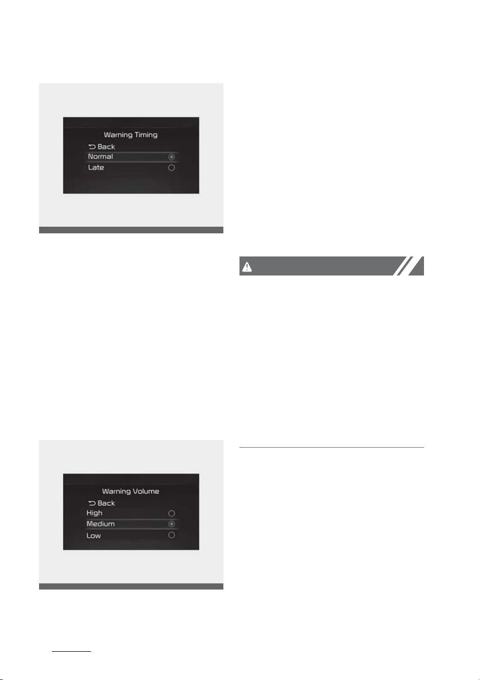
Driving your vehicle
1146
Safe Exit Assist (SEA)
Warning Timing
With the ENGINE START/STOP but
-
ton in the ON position, select 'Driver
Assistance → Warning Timing' from
the Settings menu to change the
initial warning activation time for
Safe Exit Assist.
When the vehicle is first delivered,
Warning Timing is set to 'Normal. If
you change the Warning Timing, the
warning time of other Driver Assis
-
tance systems may change.
Warning Volume
With the ENGINE START/STOP but
-
ton in the ON position, select 'Driver
Assistance → Warning Volume' from
the Settings menu to change the
Warning Volume 'High', 'Medium',
'Low' or 'Off' for Safe Exit Assist.
However, when Warning Volume is
turned off, the steering wheel
vibration function will turn on if it
was turned off.
If you change the Warning Volume,
the Warning Volume of other Driver
Assistance systems may change.
CAUTION
䳜 The setting of the Warning Timing
and Warning Volume applies to all
functions of the Safe Exit Assist.
䳜 Even though 'Normal' is selected
for Warning Timing, if the vehicles
approaches at high speed from
the rear, the initial warning acti
-
vation time may seem late.
䳜 Select 'Late' for Warning Timing
when traffic is light and when
driving speed is slow.
OMQ4AH050334
OMQ4041606
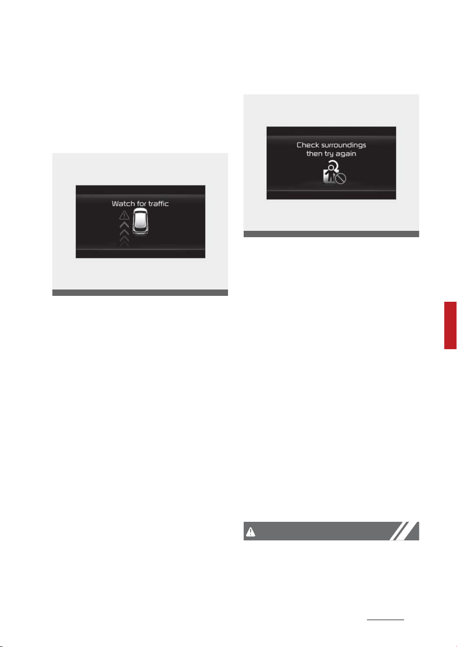
115
6
6
Driving your vehicle Safe Exit Assist (SEA)
Safe Exit Assist Operation
Warning and control
Collision Warning when exiting
vehicle
䳜 When an approaching vehicle
from the rear is detected at the
moment a door is opened, the
'Watch for traffic' warning mes
-
sage will appear on the cluster,
and an audible warning will sound.
䳜 Safe Exit Assist will warn the
driver when your vehicle speed is
below 2 mph (3 km/h), and the
speed of the approaching vehicle
from the rear is above 3 mph (5
km/h).
Safe Exit Assist linked with Elec
-
tronic child safety lock
䳜 When Electric child safety lock is
operating and an approaching
vehicle from the rear area is
detected, the rear doors cannot
be unlocked even if the driver
tries to unlock the rear doors
using the electronic child safety
lock button. The 'Check surround
-
ings then try again' warning mes
-
sage will appear on the cluster.
䳜 Safe Exit Assist will warn the
driver when vehicle speed is below
2 mph (3 km/h) and the speed of
the approaching vehicle from the
rear is above 3 mph (5 km/h).
䳜 For more details on electric child
safety lock button, refer to "Elec
-
tronic child safety lock system (if
equipped)" on page 4-16.
CAUTION
If the driver presses the electronic
child lock button again approxi
-
mately within 10 seconds after the
warning message appears, Safe Exit
OMQ4040505L
OMQ4040506L

Driving your vehicle
1166
Safe Exit Assist (SEA)
Assist judges that the driver has
unlocked the doors acknowledging
the rear status. The electronic child
safety lock will turn off (button indi
-
cator OFF) and the rear doors will
unlock. Always check the surround
-
ings before turning off the elec
-
tronic child safety lock button.
WARNING
Take the following precautions
when using Safe Exit Assist:
䳜 For your safety, change the Set
-
tings after parking the vehicle at a
safe location.
䳜 If any other function's warning
message is displayed or audible
warning is generated, Safe Exit
Assist warning message may not
be displayed and audible warning
may not be generated.
䳜 You may not hear the warning
sound of Safe Exit Assist if the
surrounding is noisy.
䳜 Safe Exit Assist does not operate
in all situations or cannot prevent
all collisions.
䳜 Safe Exit Assist may warn the
driver late or may not warn the
driver depending on the road and
driving conditions. Always check
vehicle surroundings.
䳜 The driver and passengers are
responsible for accidents that
occurs while exiting the vehicle.
Always check the surroundings
before you exit the vehicle.
䳜 Never deliberately operate Safe
Exit Assist. Doing so may lead to
serious injury or death.
䳜 Safe Exit Assist does not operate
if there is a problem with Blind-
Spot Collision-Avoidance Assist.
- The warning message of Blind-
Spot Collision-Avoidance Assist
will appears
- Blind-Spot Collision-Avoidance
Assist sensor or the sensor
surrounding is polluted or cov
-
ered
- Blind-Spot Collision-Avoidance
Assist fails to warn passengers
or falsely warn passengers
NOTICE
After the engine is turned off, Safe
Exit Assist operates approximately
for 3 minutes, but turns off imme
-
diately if the doors are locked.
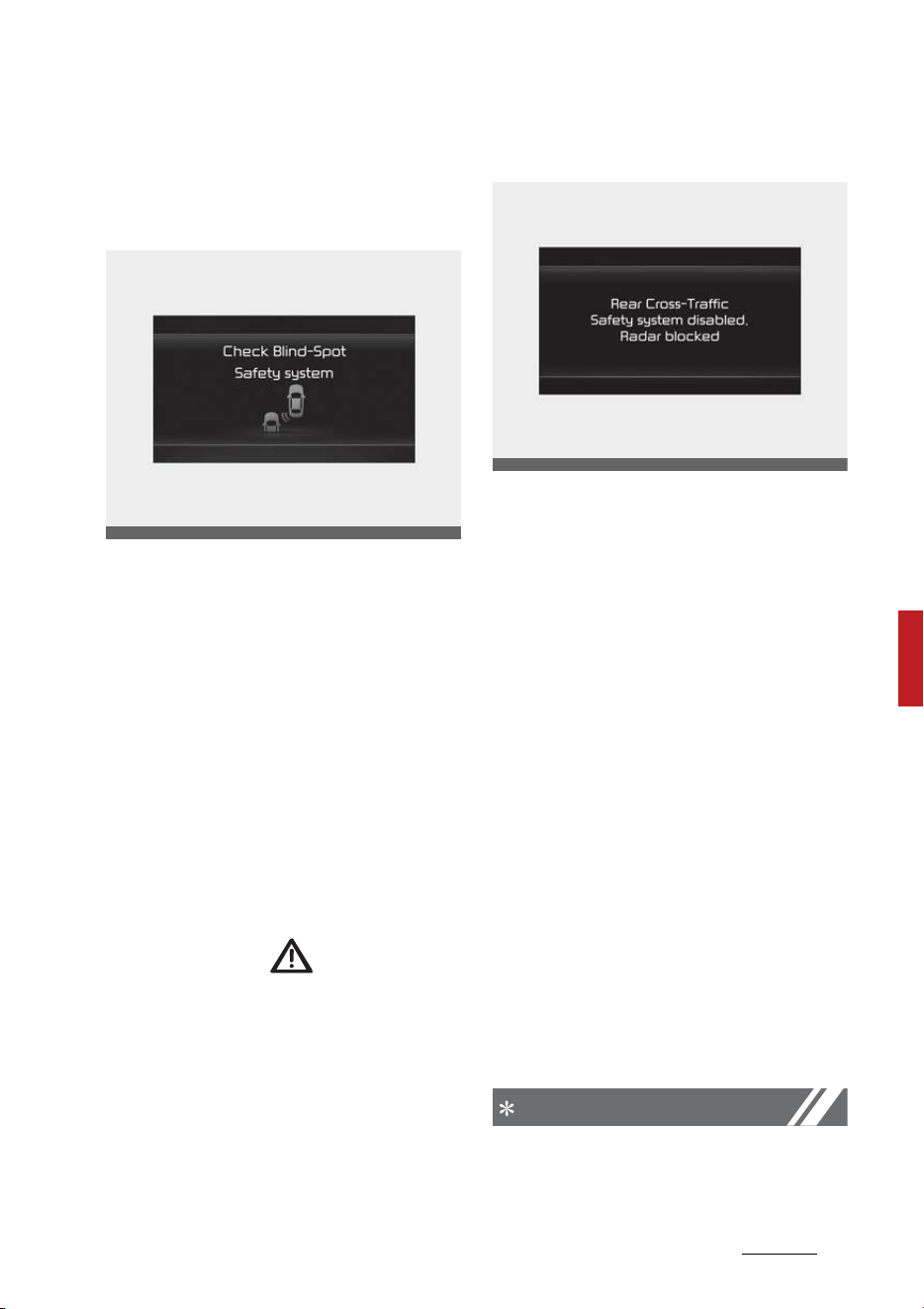
117
6
6
Driving your vehicle Safe Exit Assist (SEA)
Safe Exit Assist Malfunction and
Limitations
Safe Exit Assist malfunction
When Safe Exit Assist is not working
properly, the 'Check Blind-Spot
Safety system' warning message
will appear on the cluster, and the
function will turn off automatically
or the function will be limited. Have
the function be inspected by an
authorized Kia dealer.
When the side view mirror warning
light is not working properly, the
`Check side view mirror warning
light' warning message will appear
on the cluster for several seconds,
and the master ( ) warning light
will illuminate on the cluster. If the
master warning light illuminates,
have the vehicle inspected by an
authorized Kia dealer.
Safe Exit Assist disabled
When the rear bumper around the
rear corner radar or sensor is cov
-
ered with foreign matters, such as
snow or rain, or installing a trailer or
carrier, it can reduce the detecting
performance and temporarily limit
or disable Safe Exit Assist.
If this occurs, the 'Blind-Spot Safety
system disabled. Radar blocked'
warning message will appear on the
cluster.
The function will operate normally
when such foreign matters or
trailer, etc. is removed. Always keep
it clean.
If the function does not operate
normally after it is removed, have
your vehicle inspected by an autho
-
rized Kia dealer.
NOTICE
䳜 Even though the warning mes
-
sage does not appear on the clus
-
OMQ4050229L
OMQ4050292L

Driving your vehicle
1186
Safe Exit Assist (SEA)
ter, Safe Exit Assist may not
properly operate.
䳜 Safe Exit Assist may not properly
operate in an area (e.g., open ter
-
rain), where any substance are
not detected after turning ON the
engine.
CAUTION
Turn off Safe Exit Assist to install a
trailer, carrier, etc., or remove the
trailer, carrier, etc. to use Safe Exit
Assist.
Limitations of Safe Exit Assist
Safe Exit Assist may not operate
normally, or the function may oper
-
ate unexpectedly under the follow
-
ing circumstances:
䳜 Driving through a narrow road
where trees or grass or over
-
grown
䳜 Driving on a wet road surface,
such as a puddle in the road
䳜 The speed of the other vehicle is
very fast or slow
NOTICE
For more details on the precautions
of the rear corner radars, refer to
"Blind-Spot Collision-Avoidance
Assist (BCA) (if equipped)" on page
6-95.
WARNING
䳜 Safe Exit Assist may not operate
normally if interfered by strong
electromagnetic waves.
䳜 Safe Exit Assist may not operate
for approximately 3 seconds after
the vehicle is started, or the rear
corner radars are initialized.
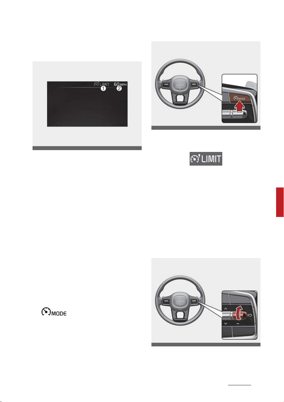
119
6
6
Driving your vehicle Manual Speed Limit Assist (MSLA)
Manual Speed Limit Assist
(MSLA)
(1) Speed Limit indicator
(2) Set speed
You can set the speed limit when
you do not want to drive over a spe
-
cific speed.
If you drive over the preset speed
limit, the warning system operates
(set speed limit will blink and chime
will sound) until the vehicle speed
returns within the speed limit.
Manual Speed Limit Assist Opera
-
tion
Setting speed limit
1. Press and hold Driving Assist
( ) button at the desired
speed.
The speed limit indicator light will
illuminate on the cluster.
2. Push the + switch up or - switch
down, and release it at the
desired speed.
Move the + switch up or - switch
down and hold it. The speed will
increase or decrease to the near
-
est multiple of five (multiple of
ten in km/h) at first, and then
increase or decrease by 5 mph (10
km/h).
OMQ4AH050312
OMQ4051128L
OMQ4051129L
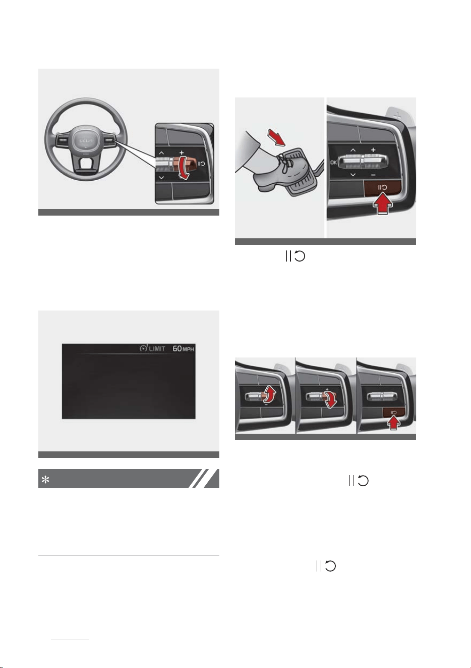
Driving your vehicle
1206
Manual Speed Limit Assist (MSLA)
3. The set speed limit will be dis
-
played on the cluster.
The set speed limit will blink and
chime will sound until you return
the vehicle speed within the speed
limit.
NOTICE
䳜 When the accelerator pedal is not
depressed beyond the pressure
point, vehicle speed will maintain
within the speed limit.
To temporarily pause Manual Speed
Limit Assist
Push the ( ) switch to temporar
-
ily pause the set speed limit. The set
speed limit will turn off but the
Speed Limit indicator will stay on.
To resume Manual Speed Limit
Assist
To resume Manual Speed Limit
Assist after the function was
paused, push the +, -, ( )switch.
If you push the + switch up or 䳍
switch down, vehicle speed will be
set to the current speed on the
cluster.
If you push the ( )switch, vehicle
speed will resume to the preset
speed.
OMQ4051130L
OMQ4AH050346
OMQ4050326L
OMQ4050205L
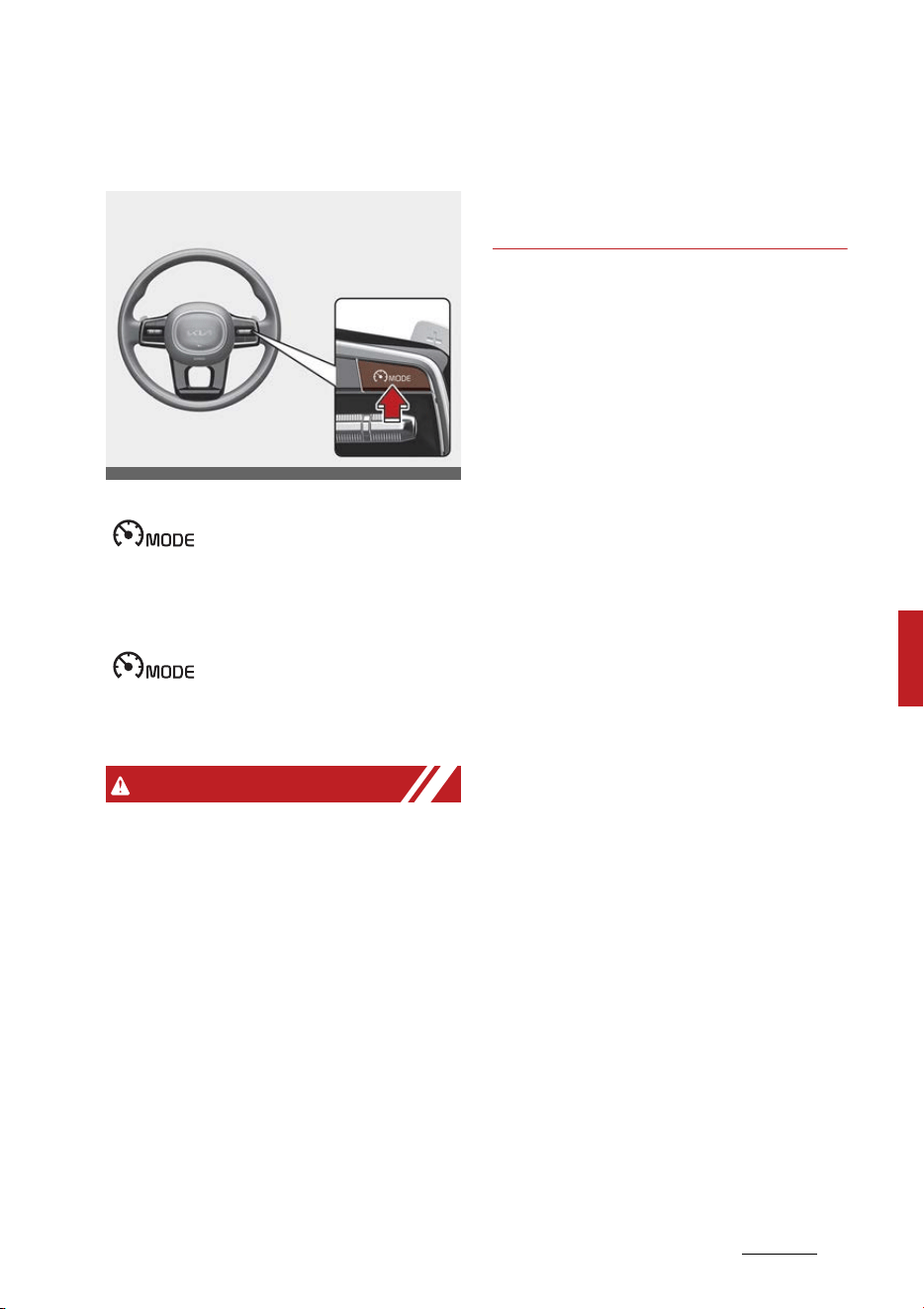
121
6
6
Driving your vehicle Manual Speed Limit Assist (MSLA)
To turn off Manual Speed Limit
Assist
Press the Driving Assist
( )button to turn Manual
Speed Limit Assist off. The Speed
Limit indicator will go off.
Always press the Driving Assist
( )button to turn Manual
Speed Limit Assist off when not in
use.
WARNING
Take the following precautions
when using Manual Speed Limit
Assist :
䳜 Always set the vehicle speed to
the speed limit in your country.
䳜 Keep Manual Speed Limit Assist
off when the function is not in
use, to avoid inadvertently setting
a speed. Check that the Speed
Limit indicator is off.
䳜 Manual Speed Limit Assist does
not substitute for proper and safe
driving. It is the responsibility of
the driver to always drive safely
and should always be aware of
unexpected and sudden situations
from occurring. Pay attention to
the road conditions at all times.
OMQ4051128L
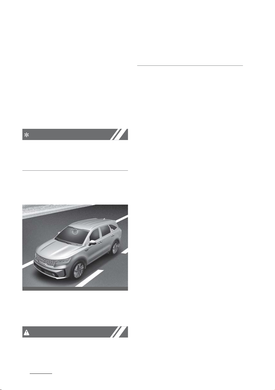
Driving your vehicle
1226
Intelligent Speed Limit Assist (ISLA)
Intelligent Speed Limit Assist
(ISLA) (if equipped)
Intelligent Speed Limit Assist uses
information from the detected road
sign and navigation system to
inform the driver of the speed limit
of the current road. Also, the func
-
tion helps the driver to maintain
within the speed limit of the road.
NOTICE
Intelligent Speed Limit Assist may
not operate properly if the function
is used in other countries.
Detecting sensor
Front view camera
Refer to the picture above for the
detailed location of the detecting
sensor.
CAUTION
For more details on the precautions
of the front view camera, refer to
"Forward Collision-Avoidance Assist
(FCA) (Sensor fusion) (if equipped)"
on page 6-73.
Intelligent Speed Limit Assist Set
-
tings
Setting
Speed limit
With the ENGINE START/STOP but
-
ton in the ON position, select or
deselect 'Driver Assistance → Intelli
-
gent Speed Limit Assist' from the
Settings menu to set whether or
not to use each function.
䳜 If 'Speed Limit Assist' is selected,
the function will inform the driver
of speed limit. In addition, the
function will inform the driver to
change set speed of Manual
Speed Limit Assist and/or Smart
Cruise Control to help the driver
stay within the speed limit.
䳜 If 'Speed Limit Warning' is
selected, the function will inform
the driver of speed limit. In addi
-
tion, the function will warn the
driver when the vehicle is driven
faster than the speed limit.
䳜 If 'Off' is selected, the function will
turn off.
Speed limit offset
With the ENGINE START/STOP but
-
ton in the ON position, when 'Driver
OMQ4H051009
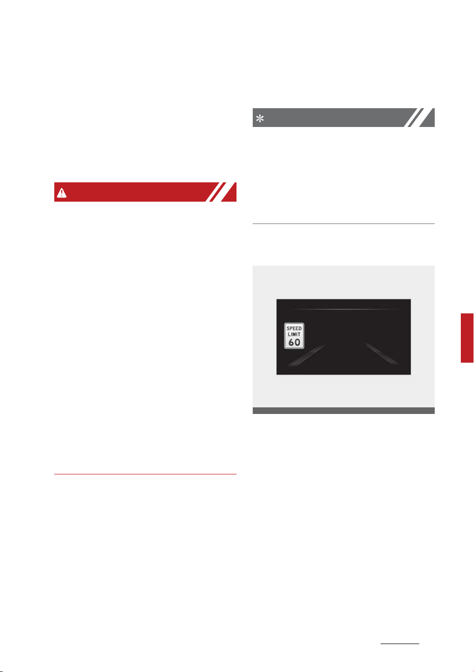
123
6
6
Driving your vehicle Intelligent Speed Limit Assist (ISLA)
Assistance → Speed Limit → Speed
Limit Offset' is selected, the Speed
Limit Offset can be changed. Speed
Limit Warning and Speed Limit
Assist will operate by applying the
Speed Limit Offset setting to the
detected speed limit.
WARNING
䳜 For your safety, change the Set
-
tings after parking the vehicle at a
safe location.
䳜 Speed Limit Assist function oper
-
ates based on the Offset setting
added to the speed limit. If you
want to change the set speed
according to the speed limit, set
the offset to '0'.
䳜 Speed Limit Warning function
warns the driver when driving
speed exceeds the speed at which
the set Offset is added to speed
limit. If you want Speed Limit
Warning to warn you immediately
when the driving speed exceeds
the speed limit, set the offset to
'0'.
Intelligent Speed Limit Assist Oper
-
ation
Intelligent Speed Limit Assist Oper
-
ation
Intelligent Speed Limit Assist will
warn and control the vehicle by 'Dis
-
playing speed limit', 'Warning over
-
speed' and 'Changing set speed'.
NOTICE
䳜 Function warning and control are
described based on the Offset set
to '0'. For details on Offset set
-
ting, refer to "Intelligent Speed
Limit Assist Settings" on page 6-
122.
Displaying speed limit
Speed limit information is displayed
on the instrument cluster.
OMQ4AH050337
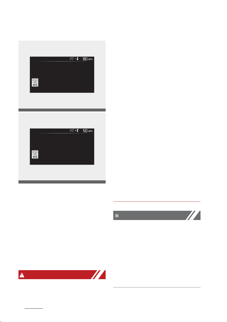
Driving your vehicle
1246
Intelligent Speed Limit Assist (ISLA)
Changing set speed
If the speed limit of the road
changes during the operation of
Manual Speed Limit Assist or Smart
Cruise Control, an arrow in the
direction of up or down is displayed
to inform the driver that the set
speed needs to be changed. At this
time, the driver can change the set
speed according to the speed limit
by using the + or 䳍 switch on the
steering wheel.
WARNING
䳜 If the Offset is set over '0', the set
speed will change to a higher
speed than the speed limit of the
road. If you want to drive below
the speed limit, set the Offset
under '0' or use the 䳍 switch on
the steering wheel to lower the
set speed.
䳜 Even after changing the set speed
according to the speed limit of the
road, the vehicle can still be driven
over the speed limit. If necessary,
depress the brake pedal to reduce
your driving speed.
䳜 If the speed limit of the road is
under 20 mph (30 km/h), the set
speed change function will not
work.
䳜 Intelligent Speed Limit Assist
operates using the speed unit in
the instrument cluster set by the
driver. If the speed unit is set to a
unit other than the speed unit
used in your country, Intelligent
Speed Limit Assist may not oper
-
ate properly.
NOTICE
䳜 For more details on function
operation of Manual Speed Limit
Assist, refer to "Manual Speed
Limit Assist (MSLA)" on page 6-
119.
䳜 For more details on operation of
Smart Cruise Control, refer to
"Smart Cruise Control (SCC) (if
equipped)" on page 6-139.
OMQ4A050357
OMQ4A050358
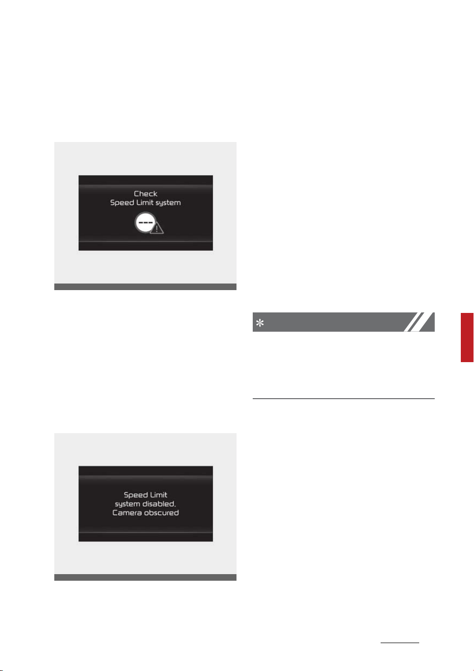
125
6
6
Driving your vehicle Intelligent Speed Limit Assist (ISLA)
Intelligent Speed Limit Assist Mal
-
function and Limitations
Intelligent Speed Limit Assist mal
-
function
When Intelligent Speed Limit Assist
is not working properly, the 'Check
speed limit system' warning mes
-
sage will appear on the cluster. If
this occurs, have the function
checked by an authorized Kia dealer.
Intelligent Speed Limit Assist dis
-
abled
When the front windshield where
the front view camera is located is
covered with foreign material, such
as snow or rain, it can reduce the
detecting performance and tempo
-
rarily limit or disable Intelligent
Speed Limit Assist.
If this occurs the 䳒Speed limit sys
-
tem disabled. Camera obscured'
warning message will appear on the
cluster. The function will operate
normally when snow, rain or foreign
material is removed.
If Intelligent Speed Limit Assist does
not operate normally after it is
removed, have the function checked
by an authorized Kia dealer.
NOTICE
Even though the warning message
or warning light does not appear on
the cluster, Intelligent Speed Limit
Assist may not operate properly.
Limitations of Intelligent Speed
Limit Assist
Intelligent Speed Limit Assist may
not operate normally, or the func
-
tion may operate unexpectedly
under the following circumstances:
䳜 The road sign is contaminated or
indistinguishable
- The road sign is difficult to see
due to bad weather, such as
rain, snow, fog, etc.
- The road sign is not clear or
damaged
OMQ4050304L
OMQ4050305L

Driving your vehicle
1266
Intelligent Speed Limit Assist (ISLA)
- The road sign is partially
obscured by surrounding
objects or shadow
䳜 The road signs do not conform to
the standard
- The text or picture on the road
sign is different from the stan
-
dard
- The road sign is installed
between the main line and the
exit road or between diverging
roads
- A conditional road sign is not
installed with a sign located on
the road to enter or exit
- A sign is attached to another
vehicle
䳜 The brightness changes sud
-
denly, for example when entering
or exiting a tunnel or passing
under a bridge
䳜 Headlamps are not used or the
brightness of the headlamps are
weak at night or in the tunnel
䳜 Road signs are difficult to recog
-
nize due to the reflection of sun
-
light, street lights, or oncoming
vehicles
䳜 The field of view of the Front view
camera is obstructed by sun glare
䳜 Driving on a road that is sharply
curved or continuously curved
䳜 Driving through speed bumps, or
driving up and down or left to
right on steep inclines
䳜 The vehicle is shaking heavily
WARNING
䳜 Intelligent Speed Limit Assist is a
supplemental function that helps
the driver to comply with the
speed limit on the road, and may
not display the correct speed limit
or control the driving speed prop
-
erly.
䳜 Always set the vehicle speed to
the speed limit in your country.
CAUTION
For more details on the limitations
of the front view camera, refer to
"Forward Collision-Avoidance Assist
(FCA) (Front view camera only) (if
equipped)" on page 6-60.
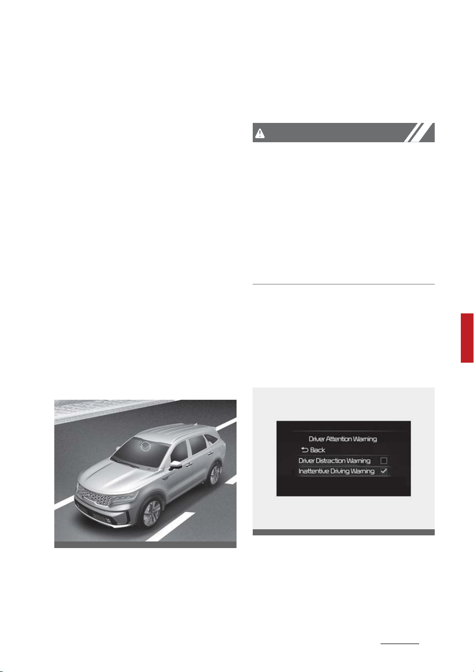
127
6
6
Driving your vehicle Driver Attention Warning (DAW)
Driver Attention Warning (DAW)
Basic function
Driver Attention Warning will help
determine the driver's attention
level by analyzing driving pattern,
driving time, etc. while vehicle is
being driven. The function will rec
-
ommend a break when the driver's
attention level falls below a certain
level.
Leading vehicle departure alert
function
Leading Vehicle Departure Alert
function will inform the driver when
the front vehicle departs from a
stop.
Detecting sensor
Front view camera
The front view camera is used as a
detecting sensor to detect driving
patterns and front vehicle departure
while vehicle is being driven.
Refer to the picture above for the
detailed location of the detecting
sensor.
CAUTION
Always keep the front view camera
in good condition to maintain opti
-
mal performance of Driver Atten
-
tion Warning.
For more details on the precautions
of the front view camera, refer to
"Forward Collision-Avoidance Assist
(FCA) (Front view camera only) (if
equipped)" on page 6-60.
Driver Attention Warning Settings
Setting
Driver Attention Warning
With the ENGINE START/STOP but
-
ton in the ON position, select or
deselect 'Driver Assistance → Driver
Attention Warning' from the Set
-
OMQ4H051009
OMQ4AH050351
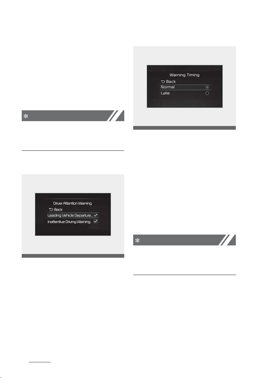
Driving your vehicle
1286
Driver Attention Warning (DAW)
tings menu to set whether or not to
use each function.
䳜 If 'Inattentive Driving Warning' is
selected, the function will inform
the driver the driver's attention
level and will recommend taking a
break when the level falls below a
certain level.
NOTICE
If the engine is restarted, Driver
Attention Warning will maintain the
last setting.
Leading Vehicle Departure Alert
䳜 If 'Leading Vehicle Departure
Alert' is selected, the function will
inform the driver when the front
vehicle departs from a stop.
Warning Timing
With the ENGINE START/STOP but
-
ton in the ON position, select 'Driver
Assistance → Warning Timing' from
the Settings menu to change the
initial warning activation time for
Driver Attention Warning.
When the vehicle is first delivered,
Warning Timing is set to 'Normal'. If
you change the Warning Timing, the
warning time of other Driver Assis
-
tance systems may change.
NOTICE
If the engine is restarted, Driver
Warning Time will maintain the last
setting.
Driver Attention Warning Operation
Basic function
Display and warning
The basic function of Driver Atten
-
tion Warning is to inform the driver
OMQ4A050338
OMQ4AH050334

129
6
6
Driving your vehicle Driver Attention Warning (DAW)
the 'Attention Level' and to warn
the driver 'Consider taking a break'.
Attention level
Function off
Standby
Attentive driving
Inattentive driving
䳜 The driver can monitor his/her
driving conditions on the cluster.
- When the 'Inattentive Driving
Warning' is deselected from the
Settings menu, 'System Off' is
displayed.
- The function will operate when
vehicle speed is between 0 ~
110 mph (0 ~ 180 km/h).
- When vehicle speed is not
within the operating speed, the
message 'Standby' will be dis
-
played.
䳜 The driver's attention level is dis
-
played on the scale of 1 to 5. The
OMQ4050113L
OMQ4050117L
OMQ4050114L
OMQ4050115L
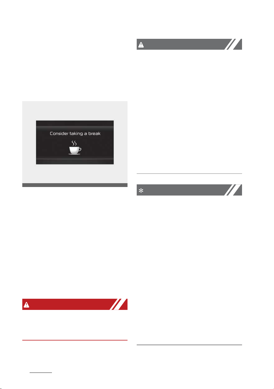
Driving your vehicle
1306
Driver Attention Warning (DAW)
lower the level is, the more inat
-
tentive the driver is.
䳜 The level decreases when the
driver does not take a break for a
certain period of time.
Taking a break
䳜 The 'Consider taking a break'
message will appear on the clus
-
ter and an audible warning will
sound to suggest that the driver
take a break, when the driver's
attention level is below 1.
䳜 Driver Attention Warning will not
suggest a break when the total
driving time is shorter than 10
minutes or 10 minutes has not
passed after the last break was
suggested.
WARNING
For your safety, change the Set
-
tings after parking the vehicle at a
safe location.
CAUTION
䳜 Driver Attention Warning may
suggest a break depending on the
driver's driving pattern or habits,
even if the driver doesn't feel
fatigue.
䳜 Driver Attention Warning is a sup
-
plemental function and may not
be able to determine whether the
driver is inattentive.
䳜 The driver who feels fatigued
should take a break at a safe
location, even though there is no
break suggestion by Driver Atten
-
tion Warning.
NOTICE
䳜 For more details on setting the
functions in the infotainment
system, refer to the infotainment
system manual.
䳜 Driver Attention Warning will
reset the last break time to 00:00
in the following situations:
- The engine is turned off
- The driver unfastens the seat
belt and opens the driver's door.
- The vehicle is stopped for more
than 10 minutes.
䳜 When the driver resets Driver
Attention Warning, the last break
time is set to 00:00 and the
driver's attention level is set to
High.
OMQ4050116L
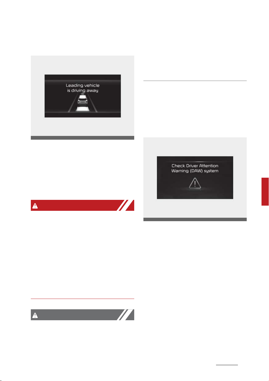
131
6
6
Driving your vehicle Driver Attention Warning (DAW)
Leading vehicle departure alert
function
When the front vehicle departs from
a stop, Leading Vehicle Departure
Alert will inform the driver by dis
-
playing the 'Leading vehicle is driving
away' message on the cluster and
an audible warning will sound.
WARNING
䳜 If any other function's warning
message is displayed or audible
warning is generated, Leading
Vehicle Departure Alert warning
message may not be displayed
and audible warning may not be
generated.
䳜 The driver should hold the
responsibility to safely drive and
control the vehicle.
CAUTION
䳜 Leading Vehicle Departure Alert is
a supplemental function and may
not alert the driver whenever the
front vehicle departs from a stop.
䳜 Always check the front of the
vehicle and road conditions before
departure.
Driver Attention Warning Malfunc
-
tion and Limitations
Driver Attention Warning Malfunc
-
tion and Limitations
When Driver Attention Warning is
not working properly, the 'Check
Driver Attention Warning (DAW)
system' warning message will
appear on the cluster. If this occurs,
have the function be inspected by
an authorized Kia dealer.
Limitations of Driver Attention
Warning
Driver Attention Warning may not
work properly in the following situa
-
tions:
䳜 The vehicle is driven violently
OMQ4040507L
OMQ4050118L
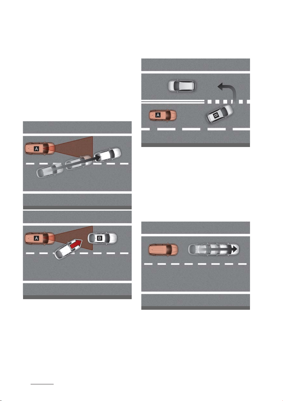
Driving your vehicle
1326
Driver Attention Warning (DAW)
䳜 The vehicle intentionally crosses
over lanes frequently
䳜 The vehicle is controlled by Driver
Assistance system, such as Lane
Keeping Assist
Leading vehicle departure alert
feature
䳜 When the vehicle cuts in
[A]: Your vehicle, [B]: Front vehicle
If a vehicle cuts in front of your
vehicle, Leading Departure Alert
may not operate properly.
䳜 When the vehicle ahead sharply
steers
[A]: Your vehicle, [B]: Front vehicle
If the vehicle in front makes a
sharp turn, such as to turn left or
right or make a U- turn, etc.,
Leading Vehicle Departure Alert
may not operate properly.
䳜 When the vehicle ahead abruptly
departures
If the vehicle in front abruptly
departures, Leading Vehicle
Departure Alert may not operate
properly.
OMQ4050121
OMQ4050122
OMQ4050246
OMQ4050124
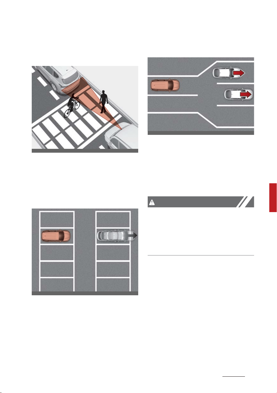
133
6
6
Driving your vehicle Driver Attention Warning (DAW)
䳜 When a pedestrian or bicycle is
between you and the vehicle
ahead
If there is a pedestrian(s) or bicy
-
cle(s) in between you and the
vehicle in front, Leading Vehicle
Departure Alert may not operate
properly.
䳜 When in a parking lot
If a vehicle parked in front drives
away from you, Leading Vehicle
Departure Alert may alert you
that the parked vehicle is driving
away.
䳜 The vehicle in front is difficult to
be specified
If you pass a tollgate or intersec
-
tion with lots of vehicles or you
drive where lanes are merged or
divided frequently, Leading Vehi
-
cle Departure Alert may not oper
-
ate properly.
CAUTION
For more details on the precautions
of the front view camera, refer to
"Forward Collision-Avoidance Assist
(FCA) (Front view camera only) (if
equipped)" on page 6-60.
ODL3059051
OMQ4050125
OMQ4050126
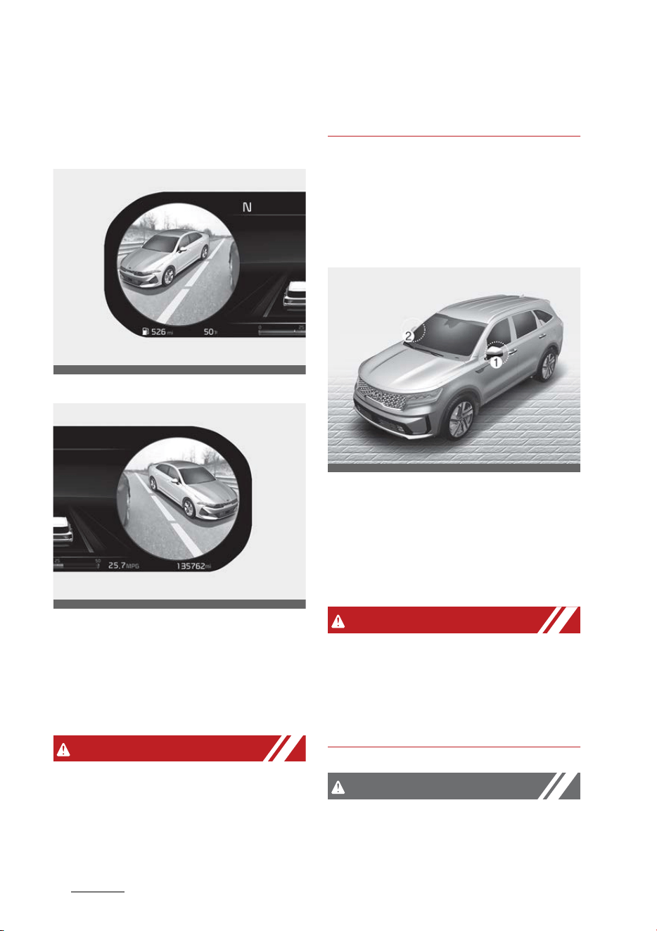
Driving your vehicle
1346
Blind-Spot View Monitor (BVM)
Blind-Spot View Monitor (BVM)
(if equipped)
Left side
Right side
Blind-Spot View Monitor displays
the rear blind spot area of the vehi
-
cle in the cluster when the turn sig
-
nal is turned on to help safely
change lanes.
WARNING
Vehicles may look closer than they
actually are. Failure to visually con
-
firm that it is safe to change lanes
before doing so may result in an
accident leading to serious injury.
* For detailed information, refer to
the infotainment system manual.
Detecting sensor
SVM-side view camera
(camera located at bottom of the
mirror)
Refer to the picture above for the
detailed location of the detecting
sensors.
WARNING
The image shown on the cluster
may differ from the actual distance
of the object. Make sure to directly
check the vehicle's surroundings for
safety.
CAUTION
If the camera lens is covered with
foreign material, the Blind-Spot
OMQ4AH050243
OMQ4AH050244
OMQ4051247R
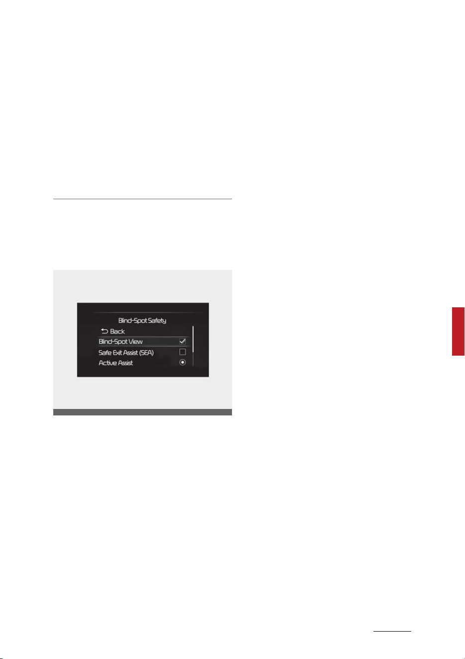
135
6
6
Driving your vehicle Blind-Spot View Monitor (BVM)
View Monitor may not operate nor
-
mally. Always keep the camera lens
clean.
However, do not use chemical sol
-
vents such as strong detergents
containing high alkaline or volatile
organic solvents (gasoline, acetone
etc.). This may damage the camera
lens.
Blind-Spot View Monitor Settings
Blind-Spot View
䳜 With the ENGINE START/STOP
button in the ON position, select
'Driver Assistance → Blind-Spot
Safety → Blind Spot View' from
the Settings menu to turn on
Blind-Spot View Monitor and
deselect to turn off the function.
Blind-Spot View Monitor Operation
Operating conditions
䳜 ENGINE START/STOP button is in
the ON position
䳜 Turn signal is ON
Off conditions
䳜 ENGINE START/STOP button is in
the OFF position
䳜 Turn signal is OFF
䳜 Hazard warning flasher is ON
䳜 Other warnings pops up and takes
priority over the Blind-Spot View
Monitor
Blind-Spot View Monitor Malfunc
-
tion
䳜 When Blind-Spot View Monitor is
not working properly, or the clus
-
ter display flickers, or the camera
image does not display normally,
have the function inspected by an
authorized Kia dealer.
OMQ4AH050340
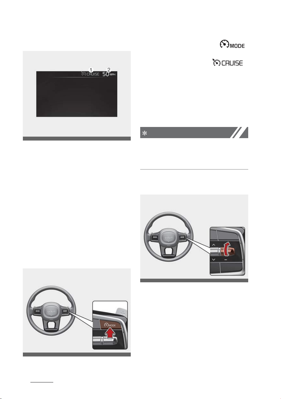
Driving your vehicle
1366
Cruise Control (CC)
Cruise Control (CC) (if equipped)
(1) Cruise indicator
(2) Set speed
Cruise Control will allow you to drive
at speeds above 20 mph (30 km/h)
without depressing the accelerator
pedal.
Cruise Control Operation
Setting speed
1. Accelerate to the desired speed,
which must be more than 20 mph
(30 km/h).
2. Press the Driving Assist ( )
button at the desired speed. The
set speed and Cruise ( )
indicator will illuminate on the
cluster.
3. Release the accelerator pedal.
Vehicle speed will maintain the set
speed even when the accelerator
pedal is not depressed.
NOTICE
On a steep slope, the vehicle may
slightly slow down or speed up while
driving uphill or downhill.
To increase set speed
䳜 Push the + switch up and release
it immediately. The set speed will
increase by 1 mph (1 km/h) each
time the switch is operated in this
manner.
䳜 Push the + switch up and hold it
while monitoring the set speed on
the cluster. The set speed will
increase to the nearest multiple
OMQ4AH050127
OMQ4051128L
OMQ4051324L
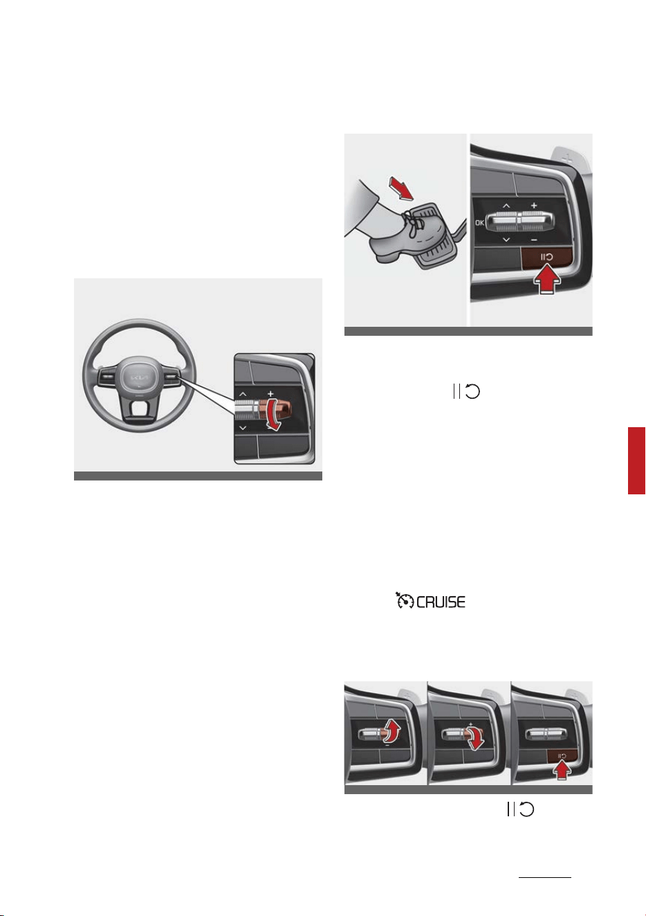
137
6
6
Driving your vehicle Cruise Control (CC)
of ten at first, and then increase
by 5 mph (10 km/h) each time the
switch is operated in this manner.
Release the switch when the
desired speed is shown and the
vehicle will accelerate to that
speed.
To decrease set speed
䳜 Push the - switch down and
release it immediately. The set
speed will decrease by 1 mph (1
km/h) each time the switch is
operated in this manner.
䳜 Push the - switch down and hold
it while monitoring the set speed
on the cluster. The set speed will
decrease to the nearest multiple
of ten at first, and then decrease
by 5 mph (10 km/h) each time the
switch is operated in this manner.
Release the switch at the speed
you want to maintain.
To temporarily cancel Cruise Con
-
trol
Cruise Control will be canceled when:
䳜 Depressing the brake pedal.
䳜 Pressing the ( ) button.
䳜 Shifting the gear to N (Neutral).
䳜 Decreasing vehicle speed to less
than approximately 20 mph (30
km/h).
䳜 ESC (Electronic Stability Control) is
operating.
䳜 Downshifting to 2nd gear when in
Manual Shift mode.
The set speed will turn off but the
Cruise ( ) indicator will
stay on.
To resume Cruise Control
Push the +, - switch or ( ) button.
OMQ4051325L
OMQ4050326L
OMQ4050205L
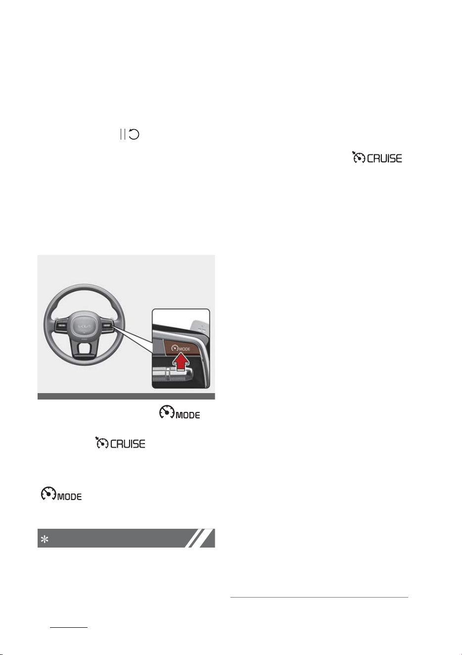
Driving your vehicle
1386
Cruise Control (CC)
If you push the + switch up or -
switch down, vehicle speed will be
set to the current speed on the
cluster.
If you press the ( ) button, vehi
-
cle speed will resume to the preset
speed.
Vehicle speed must be above 20
mph (30 km/h) for the function to
resume.
To turn off Cruise Control
Press the Driving Assist ( )
button to turn Cruise Control off.
The Cruise ( ) indicator will
go off.
Always press the Driving Assist
( ) button to turn Cruise
Control off when not in use.
NOTICE
Take the following precautions
when using Cruise Control:
䳜 Always set the vehicle speed
under the speed limit in your
country.
䳜 Keep Cruise Control off when the
function is not in use, to avoid
inadvertently setting a speed.
Check that the Cruise ( )
indicator is off.
䳜 Cruise Control does not substitute
for proper and safe driving. It is
the responsibility of the driver to
always drive safely and should
always be aware of unexpected
and sudden situations from
occurring.
䳜 Always drive cautiously to prevent
unexpected and sudden situations
from occurring. Pay attention to
the road conditions at all times.
䳜 Do not use Cruise Control when it
may be unsafe to keep the vehicle
at a constant speed:
- When driving in heavy traffic, or
when traffic conditions make it
difficult to drive at a constant
speed
- When driving on rainy, icy, or
snow-covered roads
- When driving on hilly or windy
roads
- When driving in windy areas
- When driving with limited view
(possibly due to bad weather,
such as fog, snow, rain and
sandstorm)
䳜 Do not use Cruise Control when
towing a trailer.
OMQ4051128L
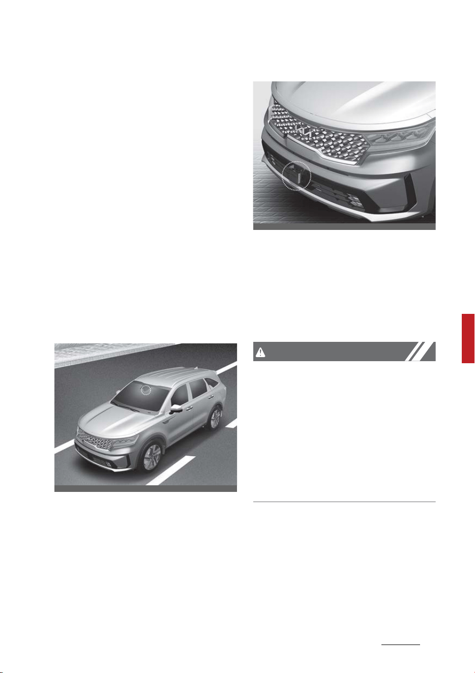
139
6
6
Driving your vehicle Smart Cruise Control (SCC)
Smart Cruise Control (SCC) (if
equipped)
Smart Cruise Control is designed to
detect the vehicle ahead and help
maintain the desired speed and
minimum distance with the vehicle
ahead.
Overtaking Acceleration Assist
While Smart Cruise Control is oper
-
ating, if the function judges that the
driver is determined to overtake the
vehicle in front, acceleration will be
assisted.
Detecting sensor
Front view camera
Front radar
The front view camera and front
radar are used as a detecting sensor
to detect front vehicles.
Refer to the picture above for the
detailed location of the detecting
sensor.
CAUTION
Always keep the front view camera
and front radar in good condition to
maintain optimal performance of
Smart Cruise Control. For more
details on the precautions of the
front view camera and front radar,
refer to "Forward Collision-Avoid
-
ance Assist (FCA) (Sensor fusion) (if
equipped)" on page 6-73.
OMQ4H051009
OMQ4051077
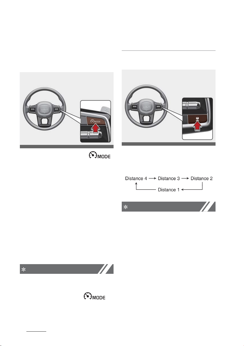
Driving your vehicle
1406
Smart Cruise Control (SCC)
Smart Cruise Control Settings
Setting
To turn on Smart Cruise Control
䳜 Press the Driving Assist ( )
button to turn on the function.
The speed will be set to the cur
-
rent speed on the cluster.
䳜 If there is no vehicle in front of
you, the set speed will be main
-
tained, but if there is a vehicle in
front of you, the speed may
decrease to maintain the distance
to the vehicle ahead. If the vehicle
ahead accelerates, your vehicle
will travel at a steady cruising
speed after accelerating to the
set speed.
NOTICE
If your vehicle speed is between 0 ~
20 mph (0 ~ 30 km/h) when you
press the Driving Assist ( )
button, the Smart Cruise Control
speed will be set to 20 mph (30 km/
h).
To set vehicle distance
Each time the Vehicle Distance but
-
ton is pressed, the vehicle to vehicle
distance changes as follows:
NOTICE
䳜 If you drive at 56 mph (90 km/h),
the distance is maintained as fol
-
lows:
Distance 4 - approximately 172
ft. (52.5 m)
Distance 3 - approximately 130
ft. (40 m)
Distance 2 - approximately 106
ft. (32.5 m)
Distance 1 - approximately 82 ft.
(25 m)
䳜 The distance is set to the last set
distance when the engine is
OMQ4051128L
OMQ4051265
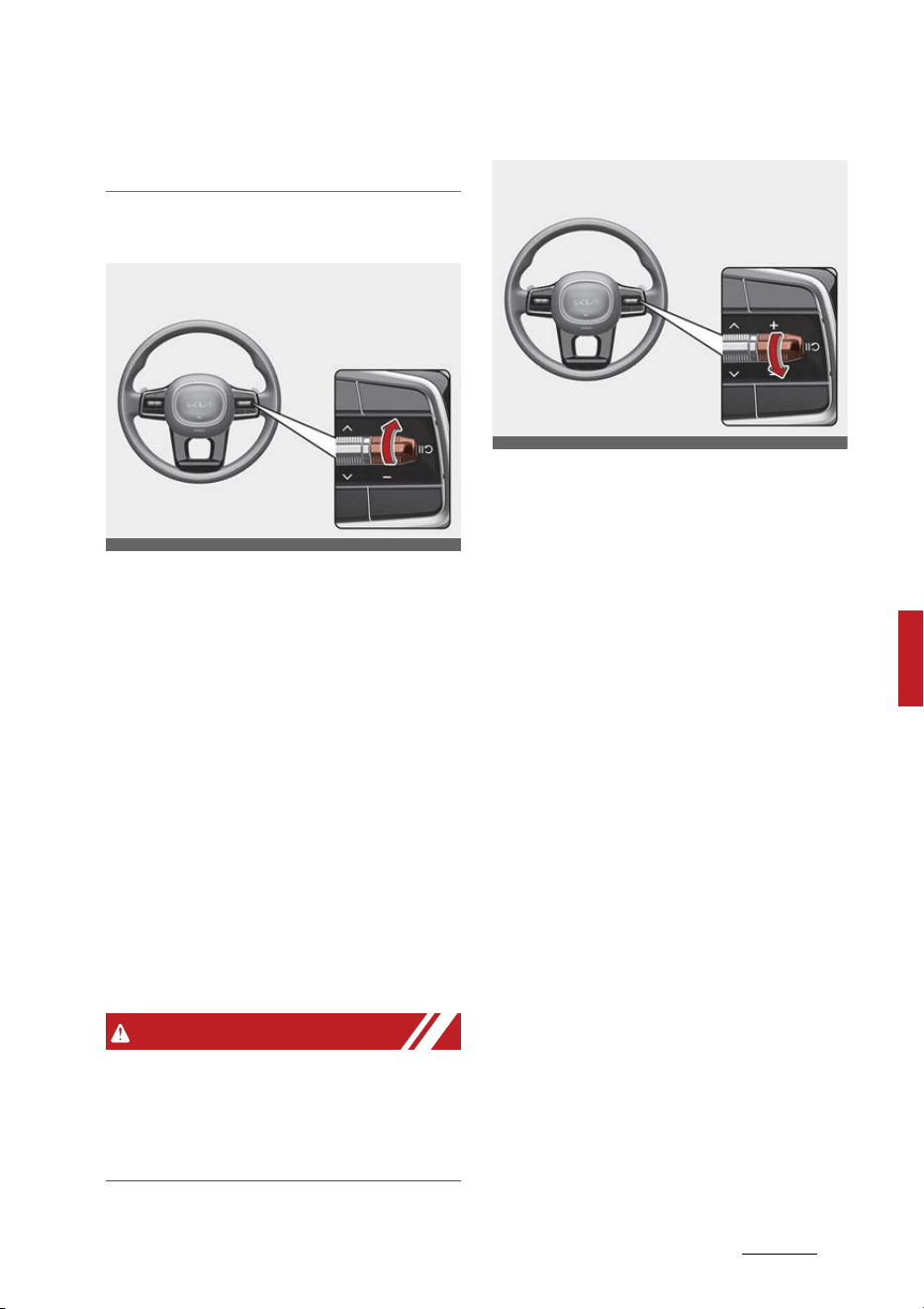
141
6
6
Driving your vehicle Smart Cruise Control (SCC)
restarted, or when the function
was temporarily canceled.
To increase set speed
䳜 Push the + switch up and release
it immediately. The set speed will
increase by 1 mph (1 km/h) each
time the switch is operated in this
manner.
䳜 Push the + switch up and hold it
while monitoring the set speed on
the cluster. The set speed will
increase by 5 mph (10 km/h) each
time the switch is operated in this
manner. Release the switch when
the desired speed is shown, and
the vehicle will accelerate to that
speed. You can set the speed to
110 mph (180 km/h).
WARNING
Check the driving condition before
using the + switch. Driving speed
may sharply increase when you
push up and hold the + switch.
To decrease set speed
䳜 Push the - switch down and
release it immediately. The set
speed will decrease by 1 mph (1
km/h) each time the switch is
operated in this manner.
䳜 Push the - switch down and hold
it while monitoring the set speed
on the cluster. The set speed will
decrease by 5 mph (10 km/h)
each time the switch is operated
in this manner.
Release the switch at the speed
you want to maintain. You can set
the speed to 20 mph (30 km/h).
OMQ4051129L
OMQ4051130L
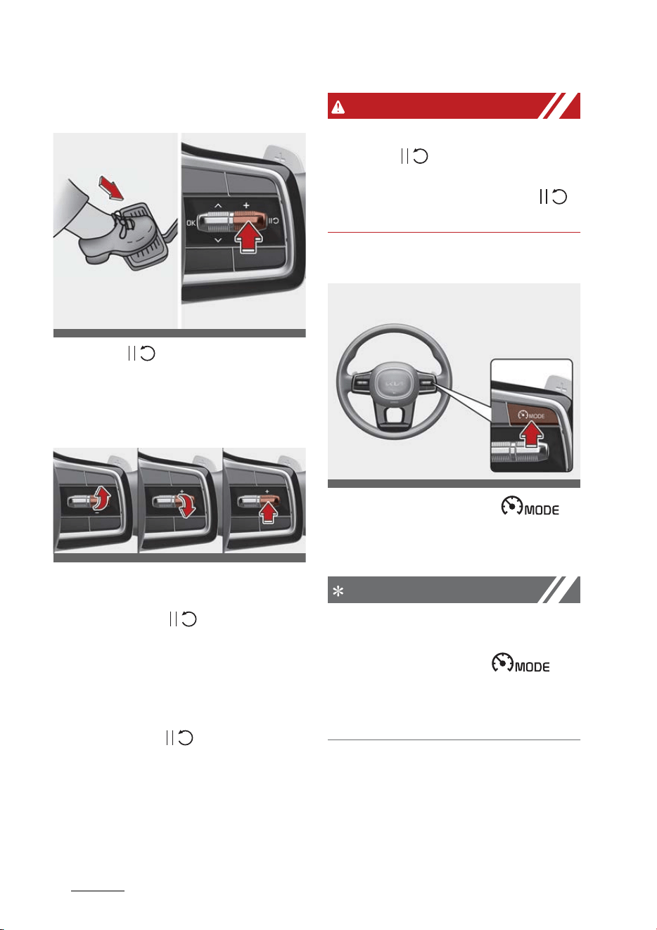
Driving your vehicle
1426
Smart Cruise Control (SCC)
To temporarily cancel Smart Cruise
Control
Press the ( ) switch or depress
the brake pedal to temporarily can
-
cel Smart Cruise Control.
To resume Smart Cruise Control
To resume Smart Cruise Control
after the function was canceled,
push the +, - or ( ) switch.
If you push the + switch up or -
switch down, vehicle speed will be
set to the current speed on the
cluster.
If you push the ( ) switch, vehicle
speed will resume to the preset
speed.
WARNING
Check the driving condition before
using the ( ) switch. Driving
speed may sharply increase or
decrease when you press the ( )
switch.
To turn off Smart Cruise Control
Press the Driving Assist ( )
button to turn Smart Cruise Control
off.
NOTICE
If your vehicle is equipped with Man
-
ual Speed Limit Assist, press and
hold the Driving Assist ( )
button to turn off Smart Cruise
Control. However Manual Speed
Limit Assist will turn on.
Based on Drive Mode
Smart Cruise Control will change
acceleration based on the drive
mode selected from Drive Mode
OMQ4050131L
OMQ4050205
OMQ4051128L
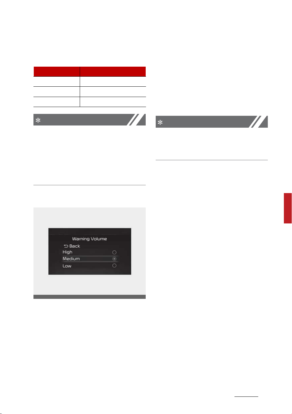
143
6
6
Driving your vehicle Smart Cruise Control (SCC)
Integrated Control function. Refer to
the following chart.
NOTICE
䳜 For more details on Drive Mode,
refer to "Drive mode integrated
control system" on page 6-55.
䳜 In vehicles without Drive Mode,
Smart Cruise Control accelerate
the vehicle in 'Normal' level.
Warning Volume
With the ENGINE START/STOP but
-
ton in the ON position, select 'Driver
Assistance → Warning Volume' from
the Settings menu to change the
Warning Volume 'High', 'Medium',
'Low' or 'Off' for Smart Cruise Con
-
trol.
However, even if 'Off' is selected,
the Smart Cruise Control's Warning
Volume will not turn off but the vol
-
ume will sound as 'Low'.
If you change the Warning Volume,
the Warning Volume of other Driver
Assistance systems may change.
NOTICE
If the engine is restarted, Warning
Volume will maintain the last set
-
ting.
Smart Cruise Control Operation
Operating conditions
Smart Cruise Control will operate
when the following conditions are
satisfied.
Basic function
䳜 The gear is in D (Drive)
䳜 The driver's door is closed
䳜 EPB (Electronic Parking Brake) is
not applied
䳜 Your vehicle speed is within the
operating speed range
- 5 ~ 110 mph (10 ~ 180 km/h):
when there is no vehicle in front
- 0 ~ 110 mph (0 ~ 180 km/h):
when there is a vehicle in front
䳜 ESC (Electronic Stability Control),
TCS (Traction Control System) or
ABS is on, but not controlling the
vehicle
Drive Mode Smart Cruise Control
ECO Slow
SPORT Fast
SMART Normal
OMQ4041606
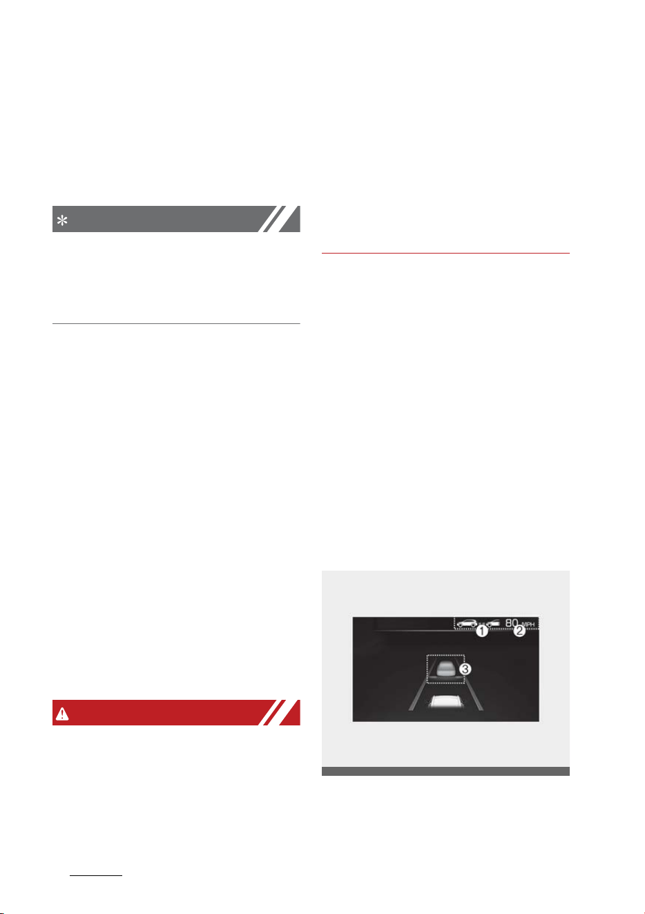
Driving your vehicle
1446
Smart Cruise Control (SCC)
䳜 Engine RPM is not in the red zone
䳜 Forward Collision-Avoidance
Assist brake control is not operat
-
ing
䳜 ISG function is not operating
NOTICE
At a stop, if there is no vehicle in
front of your vehicle, the function
will turn on when the brake pedal is
depressed.
Overtaking Acceleration Assist
Overtaking Acceleration Assist will
operate when the turn signal indica
-
tor is turned on to the left (left-
hand drive) or turned on to the right
(right-hand drive) while Smart
Cruise Control is operating, and the
following conditions are satisfied:
䳜 Your vehicle speed is above 40
mph (60 km/h)
䳜 The hazard warning flasher is off
䳜 A vehicle is detected in front of
your vehicle
䳜 Deceleration is not needed to
maintain distance with the vehicle
in front
WARNING
䳜 When the left turn signal indicator
is turned on while there is a vehi
-
cle ahead, the vehicle may accel
-
erate temporarily. Pay attention
to the road conditions at all times.
䳜 Regardless of your countries driv
-
ing direction, Overtaking Accelera
-
tion Assist will operate when the
conditions are satisfied. When
using the function in countries
with different driving direction,
always check the road conditions
at all times.
Smart Cruise Control Display and
Control
Basic function
You can see the status of the Smart
Cruise Control operation in the Util
-
ity view on the cluster. Refer to
"Instrument cluster" on page 5-80.
Smart Cruise Control will be dis
-
played as below depending on the
status of the function.
䳜 When operating
Operating
1. Whether there is a vehicle
ahead and the selected dis
-
tance level are displayed.
OMQ4AH050234
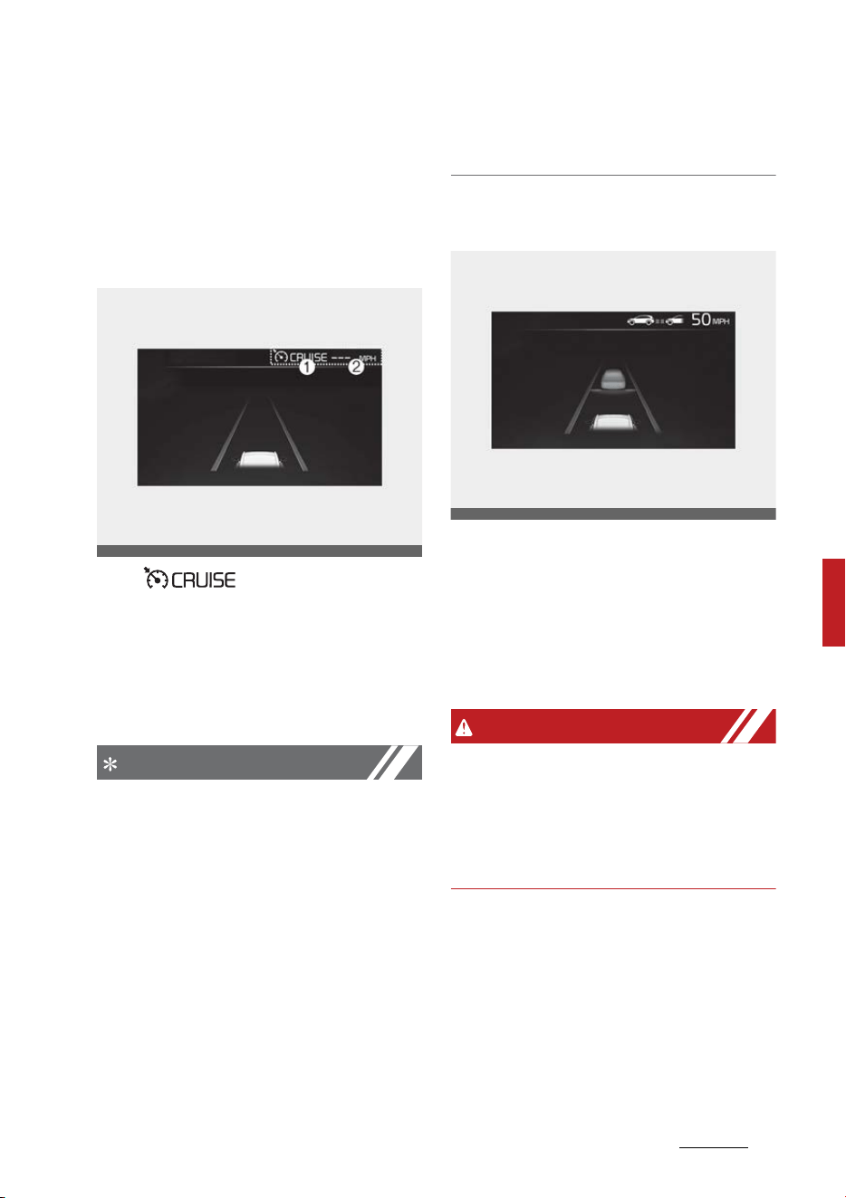
145
6
6
Driving your vehicle Smart Cruise Control (SCC)
2. Set speed is displayed.
3. Whether there is a vehicle
ahead and the selected target
distance are displayed.
䳜 When temporarily canceled
Temporarily canceled
1. ( ) indicator is dis
-
played.
2. The previous set speed is
shaded.
Vehicle ahead and distance level
are not displayed.
NOTICE
䳜 The distance of the front vehicle
on the cluster is displayed accord
-
ing to the actual distance
between your vehicle and the
vehicle ahead.
䳜 The target distance may vary
according to the vehicle speed and
the set distance level. If vehicle
speed is low, even though the
vehicle distance have changed,
the change of the target vehicle
distance may be small.
To temporarily accelerate
If you want to speed up temporarily
when Smart Cruise Control is on,
depress the accelerator pedal. While
the speed is increasing, the set
speed, distance level and target dis
-
tance will blink on the cluster.
WARNING
Be careful when accelerating tem
-
porarily, because the speed and dis
-
tance is not controlled automatically
even if there is a vehicle in front of
you.
OMQ4AH050235
OMQ4AH050132
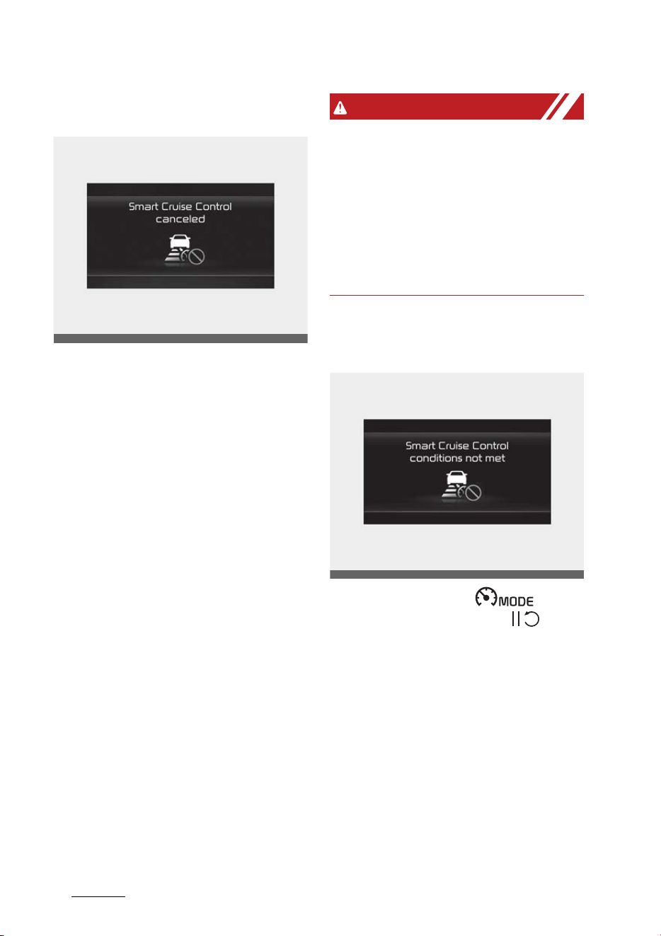
Driving your vehicle
1466
Smart Cruise Control (SCC)
Smart Cruise Control temporarily
canceled
Smart Cruise Control will be tempo
-
rarily canceled automatically when:
䳜 The vehicle speed is above 120
mph (190 km/h)
䳜 The accelerator pedal is continu
-
ously depressed for a certain
period of time
䳜 The conditions for the Smart
Cruise Control to operate is not
satisfied
If the function is temporarily can
-
celed automatically, the 'Smart
Cruise Control canceled' warning
message will appear on the cluster,
and an audible warning will sound to
warn the driver.
If the Smart Cruise Control is tem
-
porarily canceled while the vehicle is
at a standstill with the function
operating, EPB (Electronic Parking
Brake) maybe applied.
WARNING
When the function is temporarily
canceled, distance with the front
vehicle will not be maintained.
Always have your eyes on the road
while driving, and if necessary,
depress the brake pedal to reduce
your driving speed in order to main
-
tain a safe distance.
Smart Cruise Control conditions not
satisfied
If the Driving Assist ( ) but
-
ton, + switch, - switch or ( )
switch is pushed when the func
-
tion's operating conditions are not
satisfied, the 'Smart Cruise Control
conditions not met' will appear on
the cluster, and an audible warning
will sound.
OMQ4050134L
OMQ4040508L
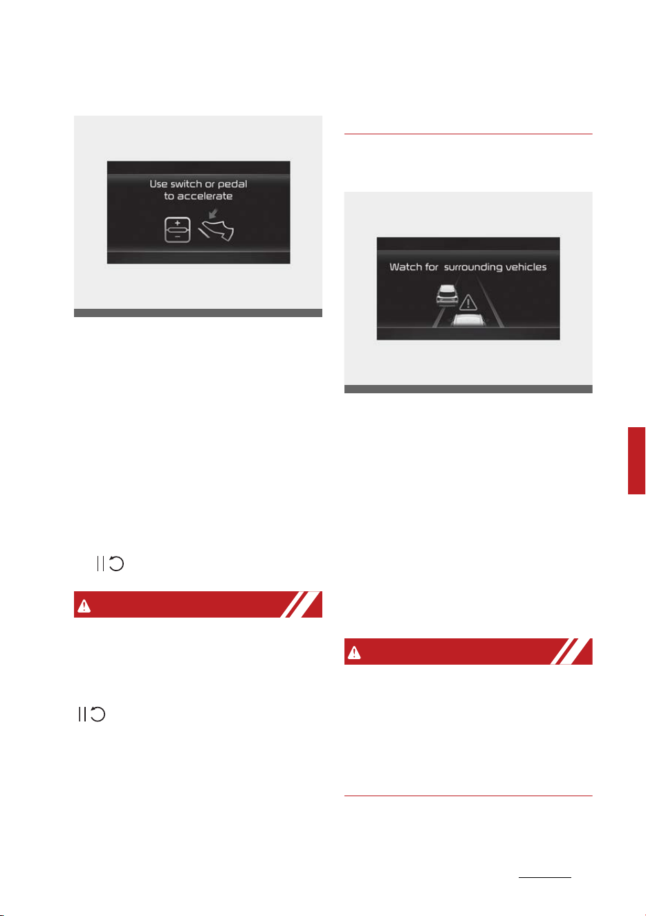
147
6
6
Driving your vehicle Smart Cruise Control (SCC)
In traffic situation
In traffic, your vehicle will stop if the
vehicle ahead of you stops. Also, if
the vehicle ahead of you starts
moving, your vehicle will start as
well.
In addition, after the vehicle has
stopped and a certain time have
passed, the 'Use switch or pedal to
accelerate' message will appear on
the cluster. Depress the accelerator
pedal or push the + switch, - switch
or ( ) switch to start driving.
WARNING
While the message is displayed on
the cluster, if there is no vehicle in
front or the vehicle is far away from
you, and the + switch, 䳍 switch or
( ) switch is pushed, Smart Cruise
Control will automatically cancel and
the EPB will be applied. However, if
the accelerator pedal is depressed,
EPB will not be applied even though
the function is canceled. Always pay
attention to the road condition
ahead.
Warning road conditions ahead
In the following situation, the 'Watch
for surrounding vehicles' warning
message will appear on the cluster,
and an audible warning will sound to
warn the driver of road conditions
ahead.
䳜 The vehicle in front disappears
when Smart Cruise Control is
maintaining the distance with the
vehicle ahead while driving below
a certain speed.
WARNING
Always pay attention to vehicles or
objects that may suddenly appear in
front of you, and if necessary,
depress the brake pedal to reduce
your driving speed in order to main
-
tain a safe distance.
OMQ4050288L
OMQ4050142L
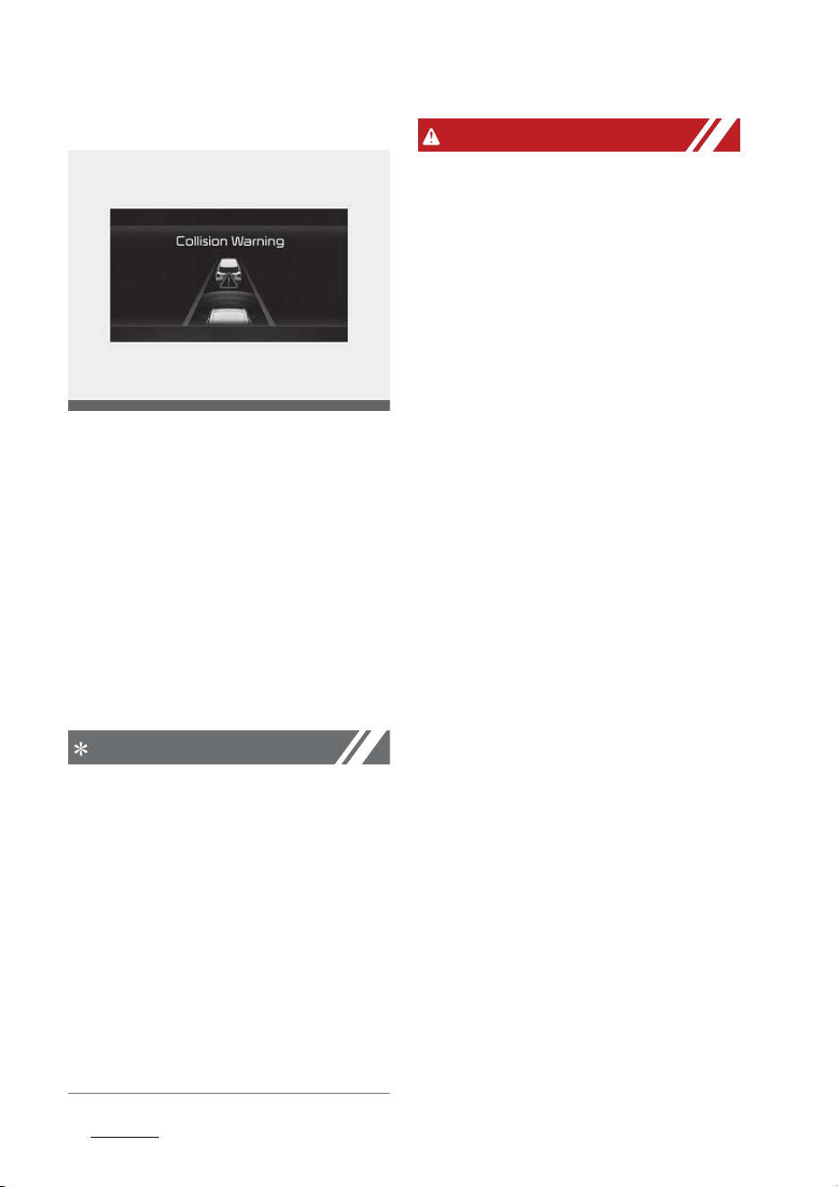
Driving your vehicle
1486
Smart Cruise Control (SCC)
Collision Warning
While Smart Cruise Control is oper
-
ating, when the collision risk with
the vehicle ahead is high, the 'Colli
-
sion Warning' warning message will
appear on the cluster, and an audi
-
ble warning will sound to warn the
driver. Always have your eyes on
the road while driving, and if neces
-
sary, depress the brake pedal to
reduce your driving speed in order
to maintain a safe distance.
NOTICE
In the following situations, Smart
Cruise Control may not warn the
driver of a collision.
䳜 The distance from the front vehi
-
cle is near, or the vehicle speed of
the front vehicle is faster or simi
-
lar with your vehicle
䳜 The speed of the front vehicle is
very slow or is at a standstill
䳜 The accelerator pedal is
depressed right after Smart
Cruise Control is turned on
WARNING
Take the following precautions
when using Smart Cruise Control:
䳜 Smart Cruise Control does not
substitute for proper and safe
driving. It is the responsibility of
the driver to always check the
speed and distance to the vehicle
ahead.
䳜 Smart Cruise Control may not
recognize unexpected and sud
-
den situations or complex driving
situations, so always pay atten
-
tion to driving conditions and con
-
trol your vehicle speed.
䳜 Keep Smart Cruise Control off
when the function is not in use to
avoid inadvertently setting a
speed.
䳜 Do not open the door or leave the
vehicle when Smart Cruise Control
is operating, even if the vehicle is
stopped.
䳜 Always be aware of the selected
speed and vehicle to vehicle dis
-
tance.
䳜 Keep a safe distance according to
road conditions and vehicle speed.
If the vehicle to vehicle distance is
too close during high-speed driv
-
ing, a serious collision may result.
䳜 When maintaining distance with
the vehicle ahead, if the front
vehicle disappears, the function
may suddenly accelerate to the
set speed. Always be aware of
OMQ4050071L

149
6
6
Driving your vehicle Smart Cruise Control (SCC)
unexpected and sudden situations
from occurring.
䳜 Vehicle speed may decrease on an
upward slope and increase on a
downward slope.
䳜 Always be aware of situations
such as when a vehicle cuts in
suddenly.
䳜 When you are towing a trailer or
another vehicle, we recommend
that Smart Cruise Control is
turned off due to safety reasons.
䳜 Turn off Smart Cruise Control
when your vehicle is being towed.
䳜 Smart Cruise Control may not
operate normally if interfered by
strong electromagnetic waves.
䳜 Smart Cruise Control may not
detect an obstacle in front and
lead to a collision. Always look
ahead cautiously to prevent unex
-
pected and sudden situations
from occurring.
䳜 Vehicles moving in front of you
with a frequent lane change may
cause a delay in the function's
reaction or may cause the func
-
tion to react to a vehicle actually
in an adjacent lane. Always drive
cautiously to prevent unexpected
and sudden situations from
occurring.
䳜 Always be aware of the surround
-
ings and drive safely, even though
a warning message does not
appear or an audible warning does
not sound.
䳜 If any other function's warning
message is displayed or warning
sound is generated, Smart Cruise
Control warning message may not
be displayed and warning sound
may not be generated.
䳜 You may not hear the warning
sound of Smart Cruise Control if
the surrounding is noisy.
䳜 The vehicle manufacturer is not
responsible for any traffic viola
-
tion or accidents caused by the
driver.
䳜 Always set the vehicle speed
under the speed limit in your
country.
NOTICE
䳜 Smart Cruise Control may not
operate for a few seconds after
the vehicle is started or the front
view camera or front radar is ini
-
tialized.
䳜 You may hear a sound when the
brake is controlled by Smart
Cruise Control.
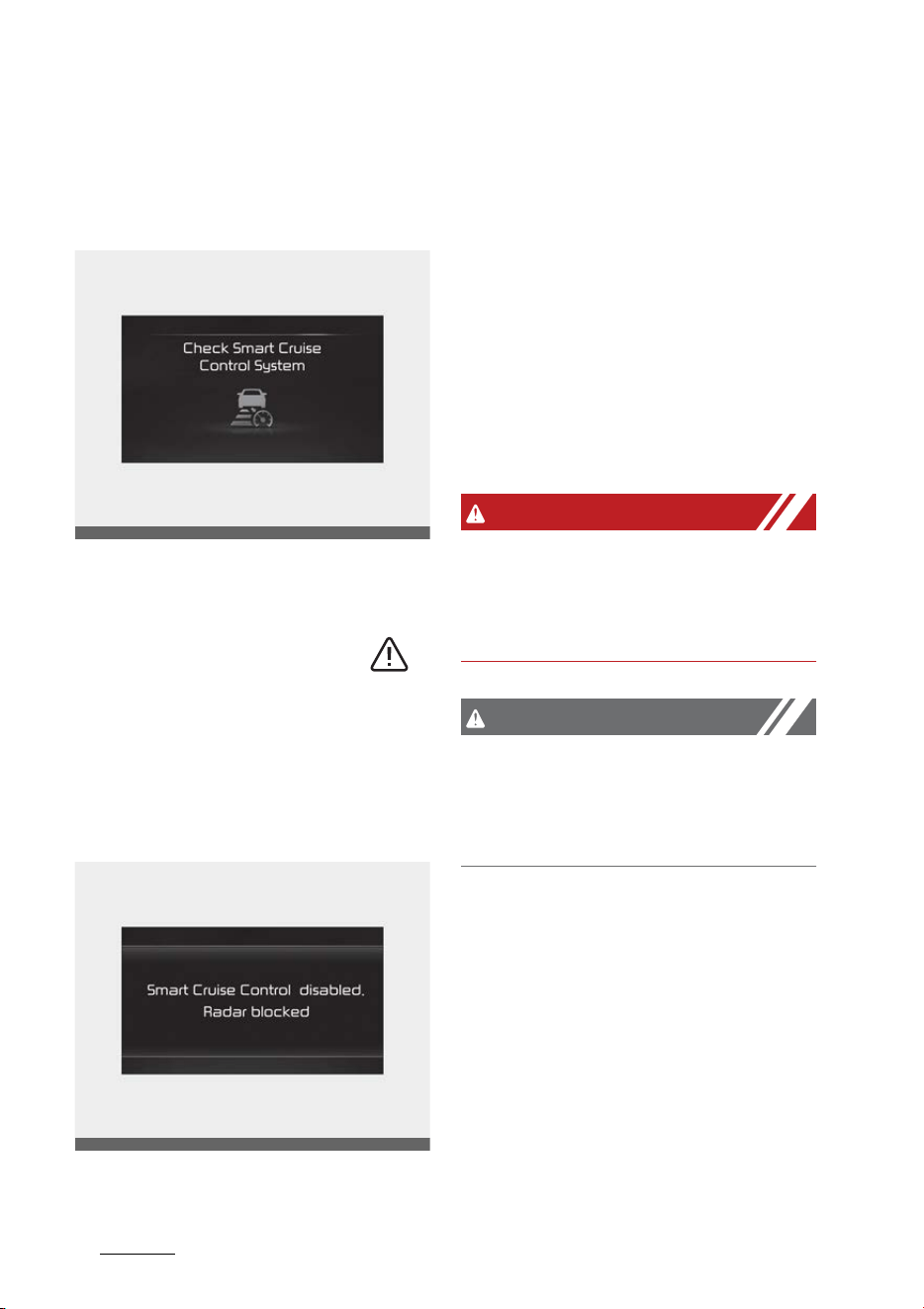
Driving your vehicle
1506
Smart Cruise Control (SCC)
Smart Cruise Control Malfunction
and Limitations
Smart Cruise Control malfunction
When Smart Cruise Control is not
working properly, the 'Check Smart
Cruise Control system' warning
message will appear, and the ( )
warning light will illuminate on the
cluster. Have the function be
inspected by an authorized Kia
dealer.
Smart Cruise Control disabled
When the front radar cover or sen
-
sor is covered with snow, rain, or
foreign material, it can reduce the
detecting performance and tempo
-
rarily limit or disable Smart Cruise
Control.
If this occurs, the 'Smart Cruise Con
-
trol disabled. Radar blocked' warning
message will appear for a certain
period of time on the cluster.
The function will operate normally
when snow, rain or foreign material
is removed.
WARNING
Even though the warning message
does not appear on the cluster,
Smart Cruise Control may not prop
-
erly operate.
CAUTION
Smart Cruise Control may not prop
-
erly operate in an area (e.g. open
terrain), where there is nothing to
detect after turning ON the engine.
Limitations of Smart Cruise Control
Smart Cruise Control may not oper
-
ate normally, or the function may
operate unexpectedly under the fol
-
lowing circumstances:
䳜 The detecting sensor or the sur
-
roundings are contaminated or
damaged
䳜 Washer fluid is continuously
sprayed, or the wiper is on
OMQ4050145L
OMQ4050144L

151
6
6
Driving your vehicle Smart Cruise Control (SCC)
䳜 The camera lens is contaminated
due to tinted, filmed or coated
windshield, damaged glass, or
stuck of foreign material (sticker,
bug, etc.) on the glass
䳜 Moisture is not removed or frozen
on the windshield
䳜 The field of view of the front view
camera is obstructed by sun glare
䳜 Street light or light from an
oncoming vehicle is reflected on
the wet road surface, such as a
puddle on the road
䳜 The temperature around the
front view camera is high or low
䳜 An object is placed on the dash
-
board
䳜 The surrounding is very bright
䳜 The surrounding is very dark, such
as in a tunnel, etc.
䳜 The brightness changes sud
-
denly, for example when entering
or exiting a tunnel
䳜 The brightness outside is low, and
the headlamps are not on or are
not bright
䳜 Driving in heavy rain or snow, or
thick fog
䳜 Driving through steam, smoke or
shadow
䳜 Only part of the vehicle is
detected
䳜 The vehicle in front has no tailla
-
mps, taillamps are located unusu
-
ally, etc.
䳜 The brightness outside is low, and
the taillamps are not on or are not
bright
䳜 The rear of the front vehicle is
small or does not look normal (i.e.
tilted, overturned, etc.)
䳜 The front vehicle's ground clear
-
ance is low or high
䳜 A vehicle suddenly cuts in front
䳜 Your vehicle is being towed
䳜 Driving through a tunnel or iron
bridge
䳜 Driving near areas containing
metal substances, such as a con
-
struction zone, railroad, etc.
䳜 A material is near that reflects
very well on the front radar, such
as a guardrail, nearby vehicle, etc.
䳜 The bumper around the front
radar is impacted, damaged or
the front radar is out of position
䳜 The temperature around the
front radar is high or low
䳜 Driving in large areas where there
are few vehicles or structures (i.e.
desert, meadow, suburb, etc.)
䳜 The vehicle in front is made of
material that does not reflect on
the front radar
䳜 Driving near a highway (or motor
-
way) interchange or tollgate
䳜 Driving on a slippery surface due
to snow, water puddle, ice, etc.
䳜 Driving on a curved road
䳜 The vehicle in front is detected
late
䳜 The vehicle in front is suddenly
blocked by a obstacle
䳜 The vehicle in front suddenly
changes lane or suddenly reduces
speed
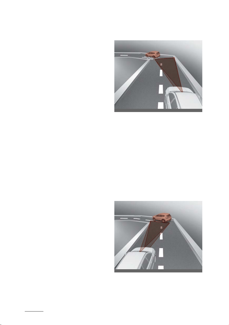
Driving your vehicle
1526
Smart Cruise Control (SCC)
䳜 The vehicle in front is bent out of
shape
䳜 The front vehicle's speed is fast or
slow
䳜 With a vehicle in front, your vehi
-
cle changes lane at low speed
䳜 The vehicle in front is covered
with snow
䳜 Unstable driving
䳜 You are on a roundabout and the
vehicle in front is not detected
䳜 You are continuously driving in a
circle
䳜 Driving in a parking lot
䳜 Driving through a construction
area, unpaved road, partial paved
road, uneven road, speed bumps,
etc.
䳜 Driving on an incline road, curved
road, etc.
䳜 Driving through a roadside with
trees or streetlights
䳜 Your vehicle is moving unstable
䳜 The adverse road conditions
cause excessive vehicle vibrations
while driving
䳜 Your vehicle height is low or high
due to heavy loads, abnormal tire
pressure, etc.
䳜 Driving through a narrow road
where trees or grass are over
-
grown
䳜 There is interference by electro
-
magnetic waves, such as driving in
an area with strong radio waves
or electrical noise
䳜 Driving on a curved road
On curves, Smart Cruise Control
may not detect a vehicle in the
same lane, and may accelerate to
the set speed. Also, vehicle speed
may rapidly decrease when the
vehicle ahead is detected sud
-
denly.
Select the appropriate set speed
on curves and apply the brake
pedal or accelerator pedal accord
-
ing to the road and driving condi
-
tions ahead.
Your vehicle speed can be reduced
due to a vehicle in the adjacent
lane.
ODEEV069237NR
ODEEV069240NR
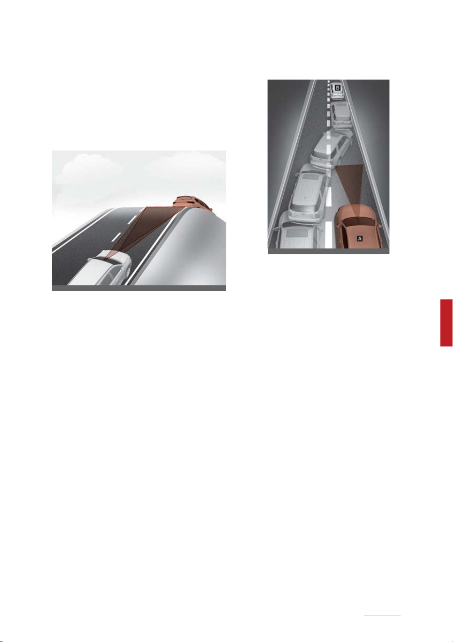
153
6
6
Driving your vehicle Smart Cruise Control (SCC)
Apply the accelerator pedal and
select the appropriate set speed.
Check to be sure that the road
conditions permit safe operation
of the Smart Cruise Control.
䳜 Driving on a sloped road
During uphill or downhill driving,
the Smart Cruise Control may not
detect a moving vehicle in your
lane, and cause your vehicle to
accelerate to the set speed. Also,
vehicle speed will rapidly decrease
when the vehicle ahead is
detected suddenly.
Select the appropriate set speed
on inclines and apply the brake
pedal or accelerator pedal accord
-
ing to the road and driving condi
-
tions ahead.
䳜 Changing lanes
[A]: Your vehicle
[B]: Lane changing vehicle
When a vehicle moves into your
lane from an adjacent lane, it can
-
not be detected by the sensor
until it is in the sensor's detection
range. Smart Cruise Control may
not immediately detect the vehi
-
cle when the vehicle changes
lanes abruptly. In this case, you
must maintain a safe braking dis
-
tance, and if necessary, depress
the brake pedal to reduce your
driving speed in order to maintain
a safe distance.
ODEEV069243NR
OADAS030SDY
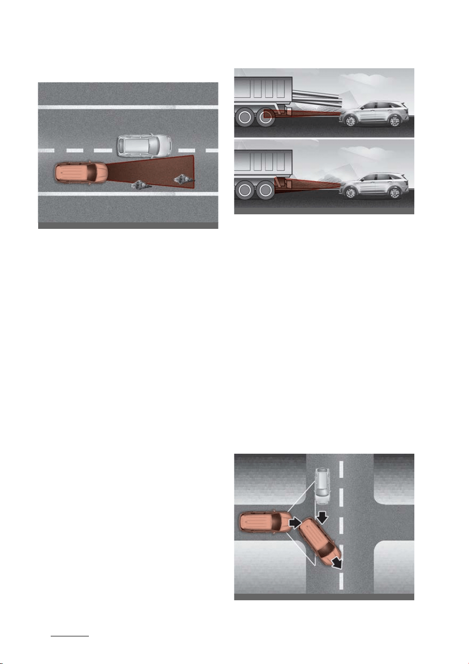
Driving your vehicle
1546
Smart Cruise Control (SCC)
䳜 Detecting vehicle
In the following cases, some vehi
-
cles in your lane cannot be
detected by the sensor:
- Vehicles offset to one side
- Slow-moving vehicles or sud
-
den-decelerating vehicles
-Oncoming vehicles
- Stopped vehicles
- Vehicles with small rear profile,
such as trailers
- Narrow vehicles, such as
motorcycles or bicycles
- Special vehicles
- Animals and pedestrians
Adjust your vehicle speed by
depressing the brake pedal
according to the road and driving
conditions ahead.
In the following cases, the vehicle
in front cannot be detected by
the sensor:
- Vehicles with higher ground
clearance or vehicles carrying
loads that stick out of the back
of the vehicle
- Vehicles that has the front
lifted due to heavy loads
- You are steering your vehicle
- Driving on narrow or sharply
curved roads
Adjust your vehicle speed by
depressing the brake pedal
according to the road and driving
conditions ahead.
OMQ4050146
OMQ4H050012
OMQ4050147
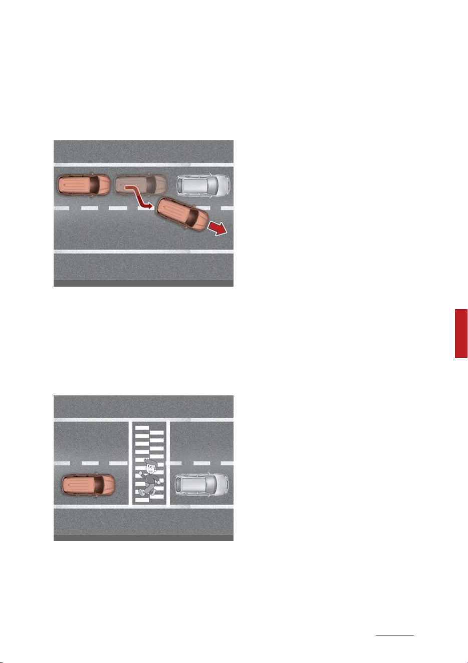
155
6
6
Driving your vehicle Smart Cruise Control (SCC)
䳜 When a vehicle ahead disappears
at an intersection, your vehicle
may accelerate.
Always pay attention to road and
driving conditions while driving.
䳜 When a vehicle in front of you
merges out of the lane, Smart
Cruise Control may not immedi
-
ately detect the new vehicle that
is now in front of you.
Always pay attention to road and
driving conditions while driving.
䳜 Always look out for pedestrians
when your vehicle is maintaining a
distance with the vehicle ahead.
This device complies with Part 15
of the FCC rules.
Operation is subject to the following
three conditions:
1. This device may not cause harm
-
ful interference.
2. This device must accept any
interference received, including
interference that may cause
undesired operation.
3. Changes or modifications not
expressly approved by the party
responsible for compliance could
void the user's authority to oper
-
ate the device.
Radio frequency radiation exposure
information:
This equipment complies with FCC
radiation exposure limits set forth
for an uncontrolled environment.
This equipment should be installed
and operated with minimum dis
-
tance of 8 in (20 cm) between the
radiator (antenna) and your body.
This transmitter must not be colo
-
cated or operating in conjunction
with any other antenna or trans
-
mitter.
OMQ4050148
OMQ4050149
Driving your vehicle
1566
Navigation-based Smart Cruise Control (NSCC)
Navigation-based Smart Cruise
Control (NSCC) (if equipped)
Navigation-based Smart Cruise
Control will help automatically
adjust vehicle speed when driving on
highways (or motorways) by using
road information from the naviga
-
tion function while Smart Cruise
Control is operating.
NOTICE
䳜 Navigation-based Smart Cruise
Control is available only on con
-
trolled access road of certain
highways.
* Controlled access road indicates
roads with limited entrances and
exits that allow uninterrupted high
speed traffic flow. Only passenger
cars and motorcycles are allowed
on controlled access roads.
䳜 Additional highways may be
expanded by future navigation
updates.
NOTICE
Navigation-based Smart Cruise
Control operates on main roads of
highways (or motorways), and does
not operate on interchanges or
junctions.
Highway Curve Zone Auto Slow
-
down
If vehicle speed is high, Highway
Curve Zone Auto Slowdown function
will temporarily decelerate your
vehicle or limit acceleration to help
you drive safely on a curve based on
the curve information from the nav
-
igation.
Highway Set Speed Auto Change
Highway Set Speed Auto Change
function automatically changes
Smart Cruise Control set speed
based on the speed limit informa
-
tion from the navigation.
Navigation-Based Smart Cruise
Control Settings
Setting
With the ENGINE START/STOP but
-
ton in the ON position, select 'Driver
Assistance → Driving Assist → High
-
way Auto Speed Change' from the
Settings menu to turn on Naviga
-
tion-based Smart Cruise Control and
deselect to turn off the function.
Available highway
(Controlled access road)
USA
Select Interstate
Highway and U.S.
(Federal) and State
Highways
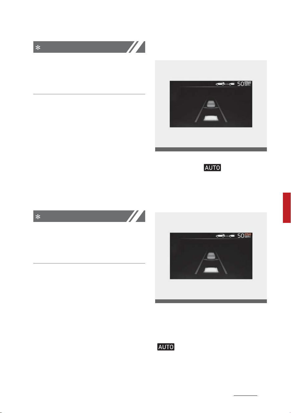
157
6
6
Driving your vehicle Navigation-based Smart Cruise Control (NSCC)
NOTICE
When there is a problem with Navi
-
gation-based Smart Cruise Control,
the function cannot be set from the
Settings menu.
Function operation
Operating conditions
Navigation-based Smart Cruise
Control is ready to operate if all of
the following conditions are satis
-
fied:
䳜 Smart Cruise Control is operating
䳜 Driving on main roads of high
-
ways (or motorways)
NOTICE
For more details on how to operate
Smart Cruise Control, refer to
"Smart Cruise Control (SCC) (if
equipped)" on page 6-139.
Function display and control
When Navigation-based Smart
Cruise Control operates, it will be
displayed on the cluster as follows:
Navigation-based Smart Cruise
Control standby
If the operating conditions are satis
-
fied, the white ( ) symbol will
illuminate.
Navigation-based Smart Cruise
Control operating
If temporary deceleration is
required in the standby state and
Navigation-based Smart Cruise
Control is operating, the green
( ) symbol will illuminate on the
cluster.
If the Highway Set Speed Auto
Change function operates, the green
OMQ4A050152
OMQ4A050248
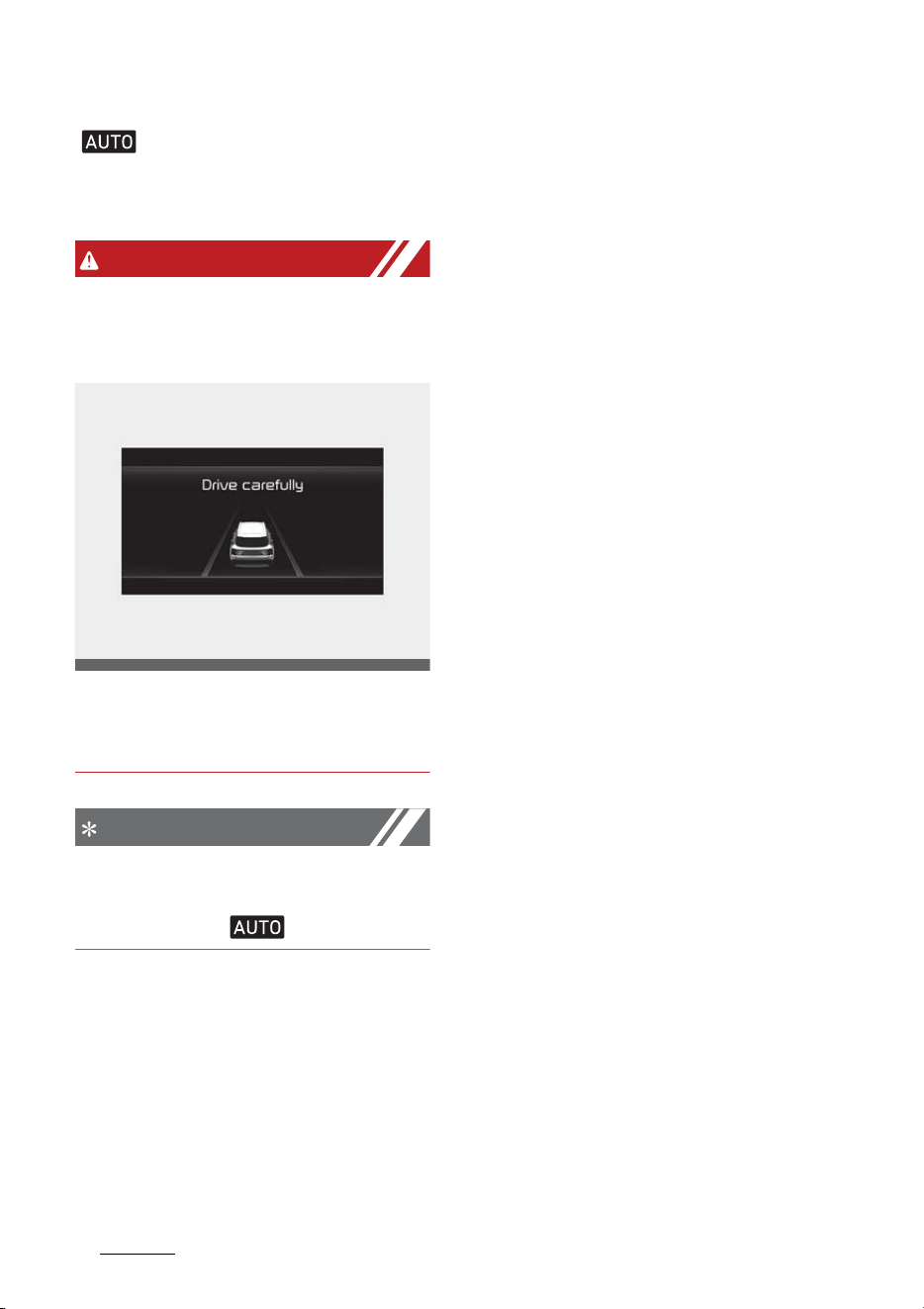
Driving your vehicle
1586
Navigation-based Smart Cruise Control (NSCC)
( ) symbol and set speed will
illuminate on the cluster, and an
audible warning will sound.
WARNING
'Drive carefully' warning message
will appear in the following circum
-
stances:
䳜 Navigation-based Smart Cruise
Control is not able to slow down
your vehicle to a safe speed
NOTICE
Highway Curve Zone Auto Slowdown
and Set Speed Auto Change function
uses the same ( ) symbol.
Highway Curve Zone Auto Slow
-
down
䳜 Depending on the curve ahead on
the highway (or motorway), the
vehicle will decelerate, and after
passing the curve, the vehicle will
accelerate to Smart Cruise Control
set speed.
䳜 Vehicle deceleration time may dif
-
fer depending on the vehicle
speed and the degree of the curve
on the road. The higher the driv
-
ing speed, deceleration will start
faster.
Highway Set Speed Auto Change
䳜 Highway Set Speed Auto Change
function will operate when Smart
Cruise Control set speed and the
highway (or motorway) speed
limit is matched.
䳜 While Highway Set Speed Auto
Change function is operating,
when the highway (or motorway),
speed limit changes, Smart Cruise
Control set speed automatically
changes to the changed speed
limit.
䳜 If Smart Cruise Control set speed
is adjusted different from the
speed limit, Highway Set Speed
Auto Change function will be in
the standby state.
䳜 If Highway Set Speed Auto
Change function has changed to
the standby state by driving on a
road other than the highway (or
motorway) main road, Highway
Set Speed Auto Change function
will operate again when you drive
on the main road again without
setting the set speed.
OMQ4040504L

159
6
6
Driving your vehicle Navigation-based Smart Cruise Control (NSCC)
䳜 If Highway Set Speed Auto
Change function has changed to
the standby state by depressing
the brake pedal, press the ( )
switch to restart the function.
䳜 Highway Set Speed Auto Change
function does not operate on
highway interchanges or junc
-
tions.
NOTICE
䳜 Highway Set Speed Auto Change
function only operates based on
the speed limits of the highway
(or motorway), it does not work
with the speed cameras.
䳜 When Highway Set Speed Auto
Change function is operating, the
vehicle automatically accelerates
or decelerates when the highway
(or motorway) speed limit
changes.
䳜 When Highway Set Speed Auto
Change function is operating, the
vehicle may warn the driver when
the vehicle's set speed limit is
above the speed camera limit.
䳜 The maximum set speed for
Highway Set Speed Auto Change
function is 90 mph (140 km/h).
䳜 If the speed limit of a new road is
not updated in the navigation,
Highway Set Speed Auto Change
function may not operate prop
-
erly.
䳜 If the speed unit is set to a unit
other than the speed unit used in
your country, Highway Set Speed
Auto Change function may not
operate properly.
Limitations of Navigation-Based
Smart Cruise Control
Navigation-based Smart Cruise
Control may not operate normally
under the following circumstances:
䳜 The navigation is not working
properly
䳜 Speed limit and road information
in the navigation is not updated
䳜 The map information and the
actual road is different because of
real-time GPS data or map infor
-
mation error
䳜 The navigation searches for a
route while driving
䳜 GPS signals are blocked in areas
such as a tunnel
䳜 The navigation is being updated
while driving
䳜 Map information is not transmit
-
ted due to infotainment system's
abnormal operation
䳜 A road that divides into two or
more roads and joins again
䳜 The driver goes off course the
route set in the navigation
䳜 The route to the destination is
changed or canceled by resetting
the navigation
䳜 The vehicle enters a service sta
-
tion or rest area
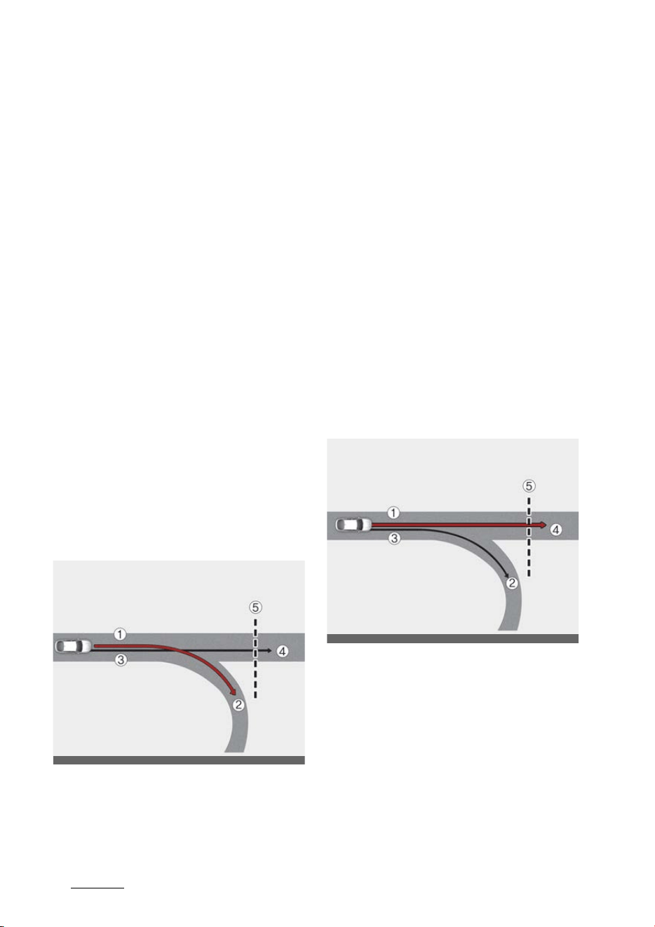
Driving your vehicle
1606
Navigation-based Smart Cruise Control (NSCC)
䳜 The speed limit of some sections
changes according to the road sit
-
uations
䳜 Android Auto or Car Play is oper
-
ating
䳜 The navigation cannot detect the
current vehicle position (ex: ele
-
vated roads including overpass
adjacent to general roads or
nearby roads exist in a parallel
way)
䳜 The navigation is being restarted
while driving
䳜 There is bad weather, such as
heavy rain, heavy snow, etc.
䳜 Driving on a road under construc
-
tion
䳜 Driving on a road that is controlled
䳜 Driving on a road that is sharply
curved
䳜 Driving on roads with intersec
-
tions, roundabouts, straight
entrances and exits, etc.
[1]: Set route, [2]: Branch line, [3]:
Driving route, [4]: Main road, [5]:
Curved road section
䳜 When there is a difference
between the navigation set route
(branch line) and the driving route
(main road), Highway Curve Zone
Auto Slowdown function may not
operate until the driving route is
recognized as the main road.
䳜 When the vehicle's driving route is
recognized as the main road by
maintaining the main road instead
of the navigation set route, High
-
way Curve Zone Auto Slowdown
function will operate. Depending
on the distance to the curve and
the current vehicle speed, vehicle
deceleration may not be sufficient
or may decelerate rapidly.
[1]: Main road, [2]: Branch line, [3]:
Driving route, [4]: Set route, [5]:
Curved road section
䳜 When there is a difference
between the navigation route
(main road) and the driving route
(branch line), Highway Curve Zone
Auto Slowdown function will
operate based on the curve infor
-
mation on the main road.
ODL3A050307
ODL3A050305
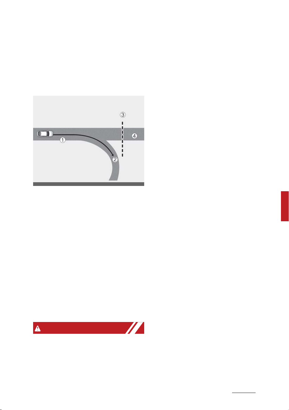
161
6
6
Driving your vehicle Navigation-based Smart Cruise Control (NSCC)
䳜 When it is judged that you are
driving out of the route by enter
-
ing the highway interchange or
junction, Highway Curve Zone
Auto Slowdown function will not
operate.
[1]: Driving route, [2]: Branch line,
[3]: Curved road section, [4]: Main
road
䳜 If there is no destination set on
the navigation, Highway Curve
Zone Auto Slowdown function will
operate based on the curve infor
-
mation on the main road.
䳜 Even if you depart from the main
road, Highway Curve Zone Auto
Slowdown function may tempo
-
rarily operate due to navigation
information of the highway curve
section.
WARNING
䳜 Navigation-based Smart Cruise
Control is not a substitute for
safe driving practices, but a con
-
venience function. Always have
your eyes on the road, and it is
the responsibility of the driver to
avoid violating traffic laws.
䳜 The navigation's speed limit infor
-
mation may differ from the
actual speed limit information on
the road. It is the driver's respon
-
sibility to check the speed limit on
the actual driving road or lane.
䳜 Navigation-based Smart Cruise
Control may not operate due to
the existence of leading vehicles
and the driving conditions of the
vehicle. Always pay attention to
road and driving conditions while
driving.
䳜 When you are towing a trailer or
another vehicle, we recommend
that Navigation-based Smart
Cruise Control is turned off due to
safety reasons.
䳜 After you pass through a tollgate
on a highway (or motorway),
Navigation-based Smart Cruise
Control will operate based on the
first lane. If you enter one of the
other lanes, the function might
not operate properly.
䳜 The vehicle will accelerate if the
driver depresses the accelerator
pedal while Navigation-based
Smart Cruise Control is operating,
and the function will not deceler
-
ate the vehicle.
䳜 If the driver accelerates and
releases the accelerator pedal
while Navigation-based Smart
Cruise Control is operating, the
vehicle may not decelerate suffi
-
ODL3A050306

Driving your vehicle
1626
Navigation-based Smart Cruise Control (NSCC)
ciently or may rapidly decelerate
to a safe speed.
䳜 If the curve is too large or too
small, Navigation-based Smart
Cruise Control may not operate.
NOTICE
䳜 The speed information on the
cluster and navigation may differ.
䳜 The time gap could occur between
the navigation's guidance and
when Navigation-based Smart
Cruise Control operation starts
and ends.
䳜 Even if you are driving at a speed
lower than Smart Cruise Control
set speed, acceleration may be
limited by the curve sections
ahead.
䳜 If Navigation-based Smart Cruise
Control is operating while leaving
the main road to enter an inter
-
change, junction, rest area, etc.,
the function may operate for a
certain period of time.
䳜 Deceleration by Navigation-based
Smart Cruise Control may feel it is
not sufficient due to road condi
-
tions such as uneven road sur
-
faces, narrow lanes, etc.
This device complies with Part 15
of the FCC rules.
Operation is subject to the following
three conditions:
1. This device may not cause harm
-
ful interference.
2. This device must accept any
interference received, including
interference that may cause
undesired operation.
3. Changes or modifications not
expressly approved by the party
responsible for compliance could
void the user's authority to oper
-
ate the device.
Radio frequency radiation exposure
information:
This equipment complies with FCC
radiation exposure limits set forth
for an uncontrolled environment.
This equipment should be installed
and operated with minimum dis
-
tance of 8 in (20 cm) between the
radiator (antenna) and your body.
This transmitter must not be colo
-
cated or operating in conjunction
with any other antenna or trans
-
mitter.
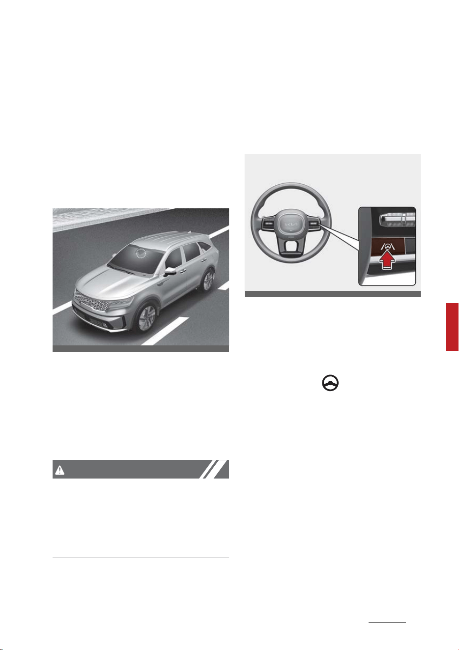
163
6
6
Driving your vehicle Lane Following Assist (LFA)
Lane Following Assist (LFA)
Lane Following Assist is designed to
help detect lane markings and/or
vehicles on the road, and assists the
driver's steering to help keep the
vehicle between lanes.
Detecting sensor
Front view camera
The front view camera is used as a
detecting sensor to detect lane
markings and front vehicles.
Refer to the picture above for the
detailed location of the detecting
sensor.
CAUTION
For more details on the precautions
of the front view camera, refer to
"Forward Collision-Avoidance Assist
(FCA) (Sensor fusion) (if equipped)"
on page 6-73.
Lane Following Assist Settings
Setting
Turning Lane Following Assist On/
Off
With the ENGINE START/STOP but
-
ton in the ON position, shortly press
the Lane Driving Assist button
located on the steering wheel to
turn on Lane Following Assist. The
white or green ( ) indicator light
will illuminate on the cluster.
Press the button again to turn off
the function.
OMQ4H051009
OMQ4051135
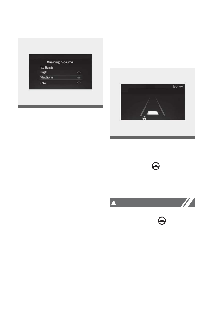
Driving your vehicle
1646
Lane Following Assist (LFA)
Warning Volume
With the ENGINE START/STOP but
-
ton in the ON position, select 'Driver
Assistance → Warning Volume' from
the Settings menu to change the
Warning Volume to 'High', 'Medium',
'Low' or 'Off' for Hands-off warning.
However, even if 'Off' is selected,
Lane Following Assist's Warning Vol
-
ume will not turn off but the volume
will sound as 'Low'.
If you change the Warning Volume,
the Warning Volume of other Driver
Assistance systems may change.
Lane Following Assist Operation
Warning and control
Lane Following Assist
If the vehicle ahead and/or both lane
markings are detected and your
vehicle speed is below 120 mph (200
km/h), the green ( ) indicator light
will illuminate on the cluster, and the
function will help the vehicle stay in
lane by assisting the steering wheel.
CAUTION
When the steering wheel is not
assisted, the green ( ) indicator
light will blink and change to white.
OMQ4041606
OMQ4AH050237
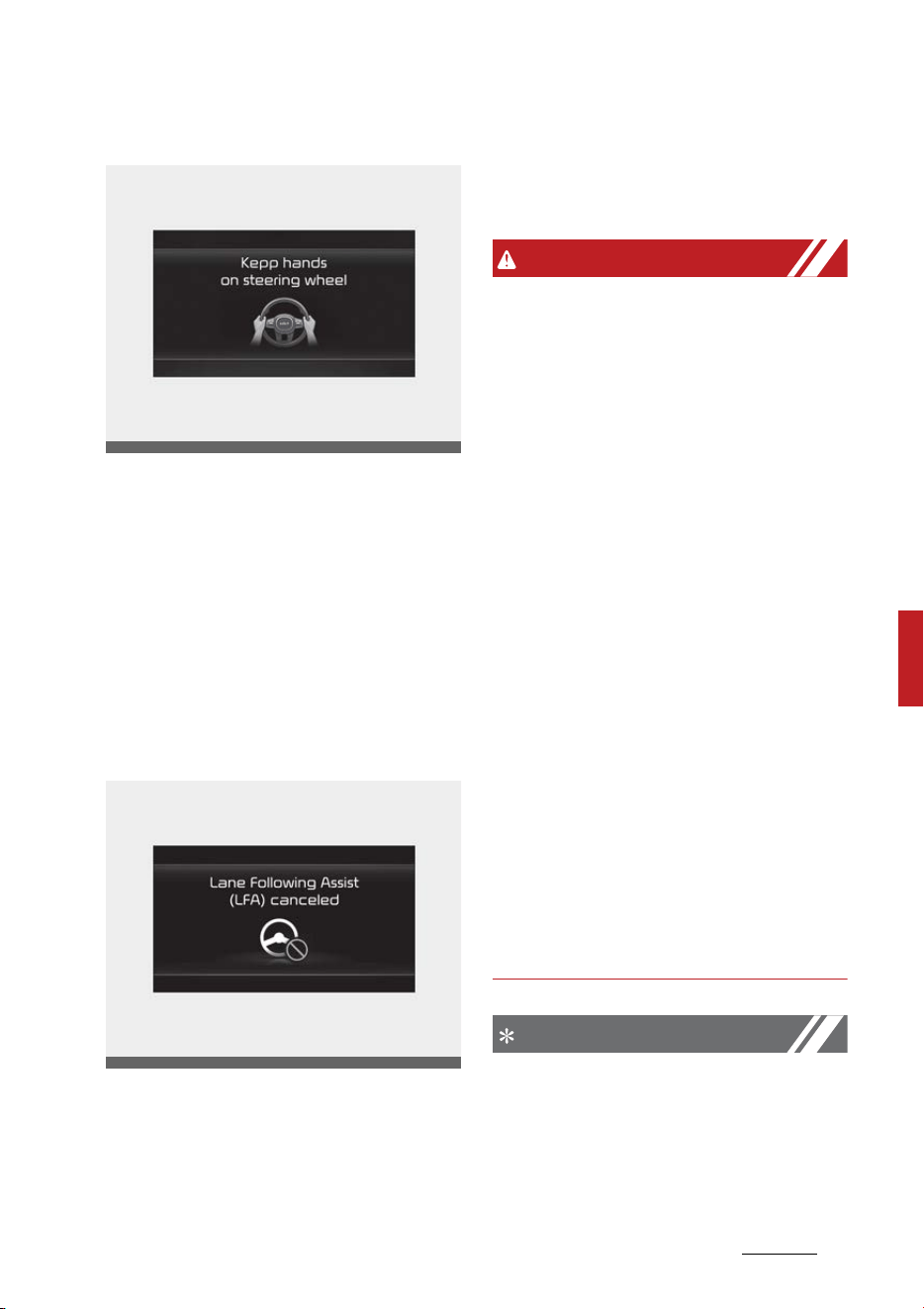
165
6
6
Driving your vehicle Lane Following Assist (LFA)
Hands-off warning
If the driver takes their hands off
the steering wheel for several sec
-
onds, the 'Keep hands on the steer
-
ing wheel' warning message will
appear and an audible warning will
sound in stages.
First stage: Warning message
Second stage: Warning message
(red steering wheel) and audible
warning
If the driver still does not have their
hands on the steering wheel after
the hands-off warning, the 'Lane
Following Assist (LFA) canceled'
warning message will appear and
Lane Following Assist will be auto
-
matically canceled.
WARNING
䳜 If you attach objects to the steer
-
ing wheel or certain amount of
power is put to the steering
wheel, the Lane Following Assist
may not assist.
䳜 Lane Following Assist does not
operate at all times. It is the
responsibility of the driver to
safely steer the vehicle and to
maintain the vehicle in its lane.
䳜 The hands䳍off warning message
may appear late depending on
road conditions. Always have your
hands on the steering wheel while
driving.
䳜 If the steering wheel is held very
lightly the hands䳍off warning
message may appear because the
function may not recognize that
the driver has their hands on the
steering wheel.
䳜 If you attach objects to the steer
-
ing wheel, the hands-off warning
may not work properly.
NOTICE
䳜 For more details on setting the
functions in the infotainment
system, refer to the infotainment
system manual.
OMQ4051155L
OMQ4040509L
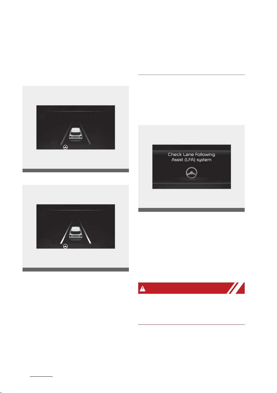
Driving your vehicle
1666
Lane Following Assist (LFA)
䳜 When both lane markings are
detected, the lane lines on the
cluster will change from grey to
white.
Lane undetected
Lane detected
䳜 If lane markings are not detected,
steering wheel control by Lane
Following Assist can be limited
depending on whether a vehicle is
in front or the driving conditions
of the vehicle.
䳜 Even though the steering is
assisted by Lane Following Assist,
the driver may control the steer
-
ing wheel.
䳜 The steering wheel may feel
heavier or lighter when the steer
-
ing wheel is assisted by Lane Fol
-
lowing Assist than when it is not.
Lane Following Assist Malfunction
and Limitations
Lane Following Assist malfunction
When Lane Following Assist is not
working properly, the 'Check Lane
Following Assist (LFA) system'
warning message will appear on the
cluster. If this occurs, have the func
-
tion be inspected by an authorized
Kia dealer.
WARNING
For more details on the function
precautions, refer to "Lane Keeping
Assist (LKA)" on page 6-89.
OMQ4AH050332
OMQ4AH050333
OMQ4050157L
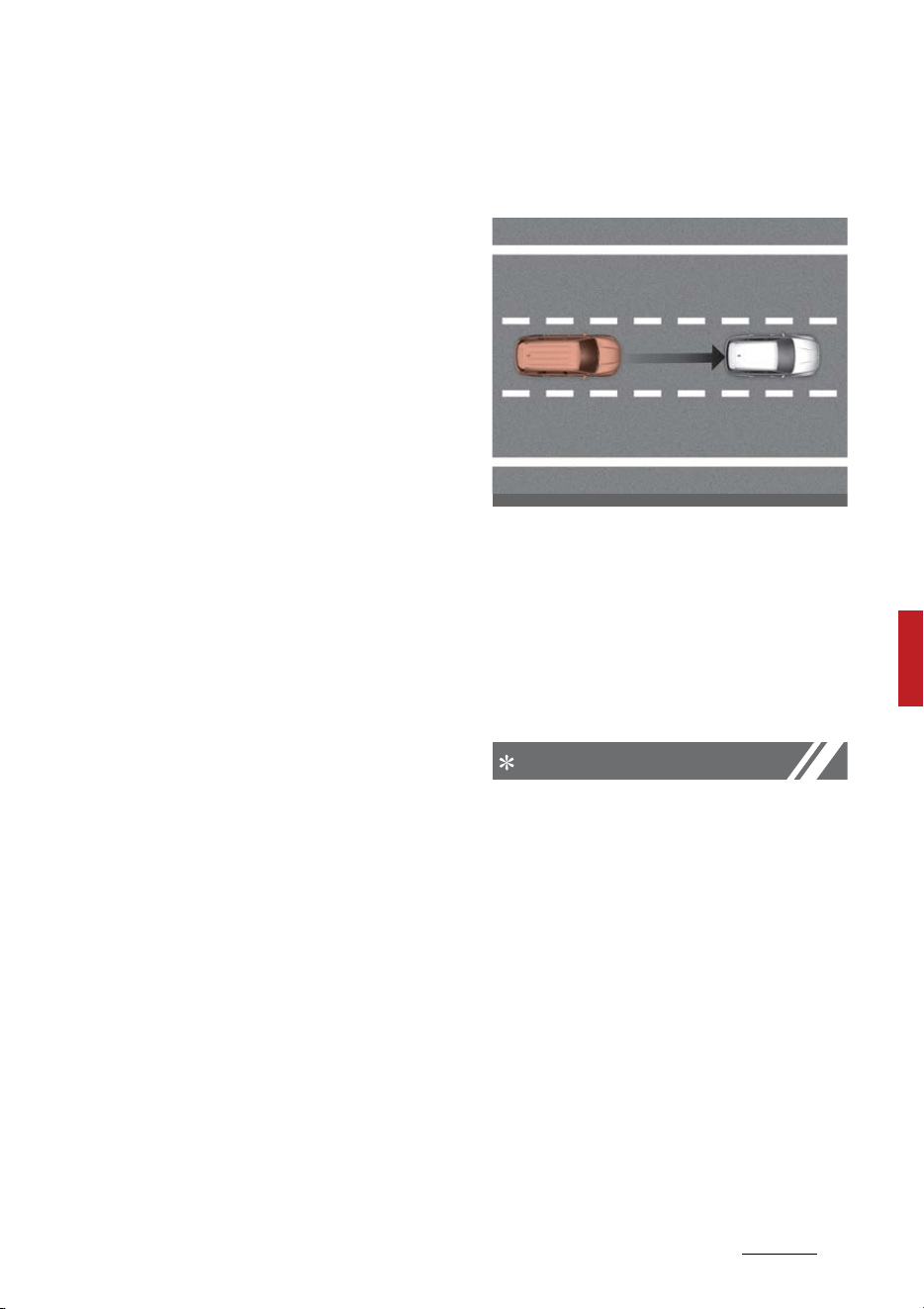
167
6
6
Driving your vehicle Highway Driving Assist (HDA)
Limitations of Lane Following
Assist
For more details on function limita
-
tions, refer to "Lane Keeping Assist
(LKA)" on page 6-89.
Highway Driving Assist (HDA) (if
equipped)
Highway Driving Assist is designed
to help detect vehicles and lanes
ahead, and help maintain distance
from the vehicle ahead, maintain
the set speed, and keep the vehicle
between lanes while driving on the
highway (or motorway).
NOTICE
䳜 Highway Driving Assist is available
only on controlled access road of
certain highways.
* Controlled access road indicates
roads with limited entrances and
exits that allow uninterrupted high
speed traffic flow. Only passenger
cars and motorcycles are allowed
on controlled access roads.
OMQ4050282L
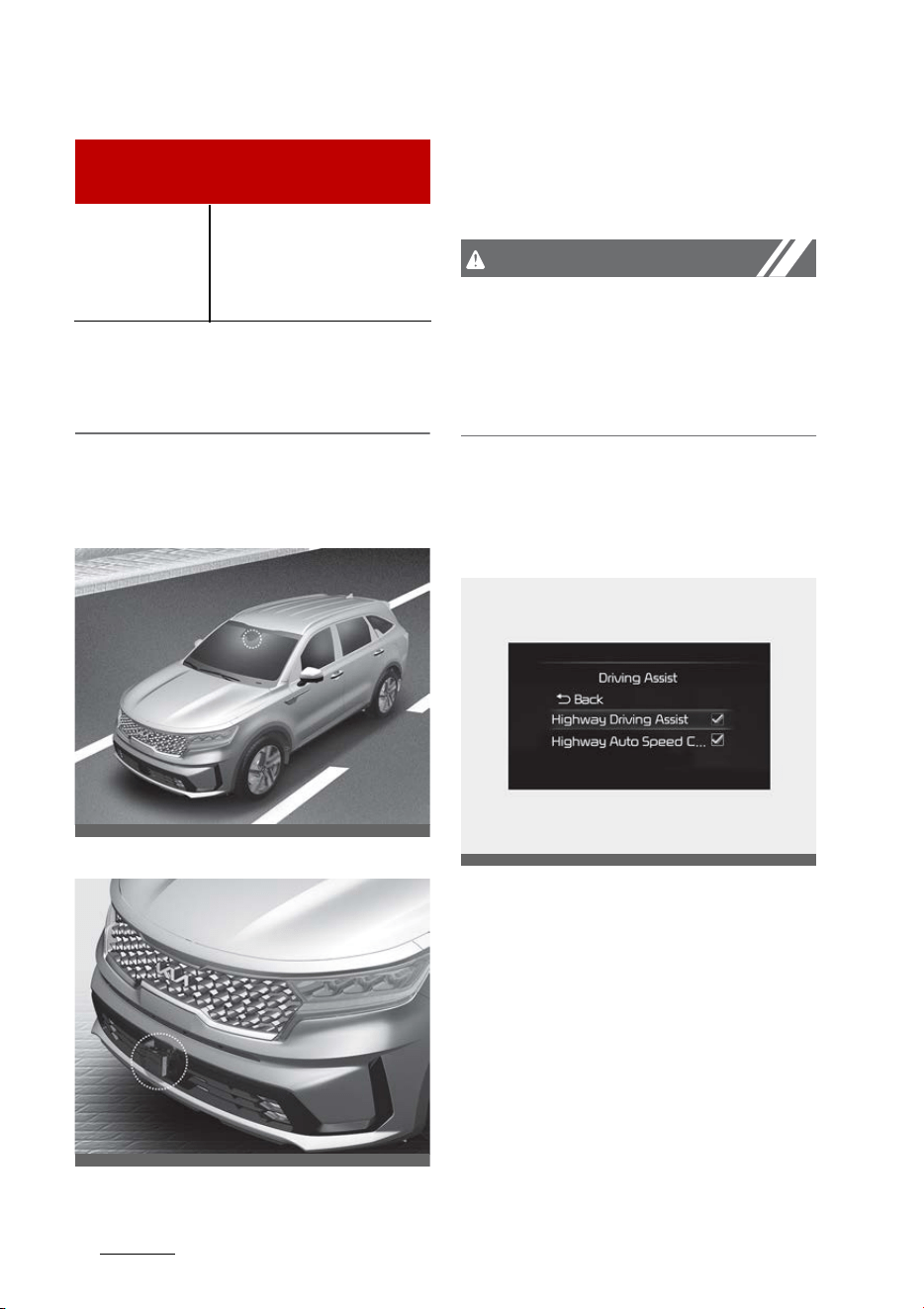
Driving your vehicle
1686
Highway Driving Assist (HDA)
䳜 Additional highways may be
expanded by future navigation
updates.
Detecting sensor
Front view camera
Front radar
Refer to the picture above for the
detailed location of the detecting
sensors.
CAUTION
For more details on the precautions
of the detecting sensors, refer to
"Forward Collision-Avoidance Assist
(FCA) (Sensor fusion) (if equipped)"
on page 6-73.
Highway Driving Assist Settings
Setting
With the ENGINE START/STOP but
-
ton in the ON position, select or
deselect 'Driver Assistance → Driv
-
ing Assist' from the Settings menu
to set whether or not to use each
function.
䳜 If 'Highway Driving Assist' is
selected, it helps maintain dis
-
tance from the vehicle ahead,
maintain the set speed, and keep
the vehicle between lanes.
Available highway
(Controlled access road)
USA
Select Interstate
Highway and U.S.
(Federal) and State
Highways
OMQ4H051009
OMQ4051077
OMQ4A050355
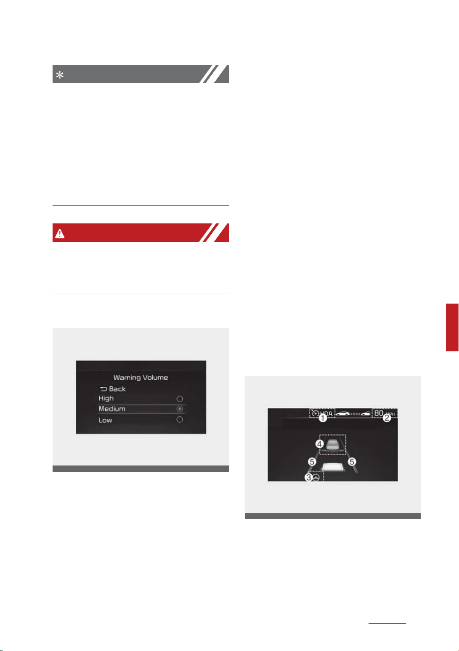
169
6
6
Driving your vehicle Highway Driving Assist (HDA)
NOTICE
䳜 If there is a problem with the
functions, the settings cannot be
changed. Have the function be
inspected by an authorized Kia
dealer.
䳜 If the engine is restarted, the
functions will maintain the last
setting.
WARNING
For your safety, change the Set
-
tings after parking the vehicle at a
safe location.
Warning Volume
With the ENGINE START/STOP but
-
ton in the ON position, select 'Driver
Assistance → Warning Volume' from
the Settings menu to change the
Warning Volume to 'High', 'Medium',
'Low' or 'Off' for Highway Driving
Assist.
However, even if 'Off' is selected,
Highway Driving Assist's Warning
Volume will not turn off but the vol
-
ume will sound as 'Low'.
If you change the Warning Volume,
the Warning Volume of other Driver
Assistance systems may change.
Highway Driving Assist Operation
Function operation
Display and control
You can see the status of the High
-
way Driving Assist operation in the
Driving Assist view on the cluster.
Refer to "LCD display" on page 4-63.
Highway Driving Assist will be dis
-
played as below depending on the
status of the function.
Operating State
OMQ4041606
OMQ4A050236
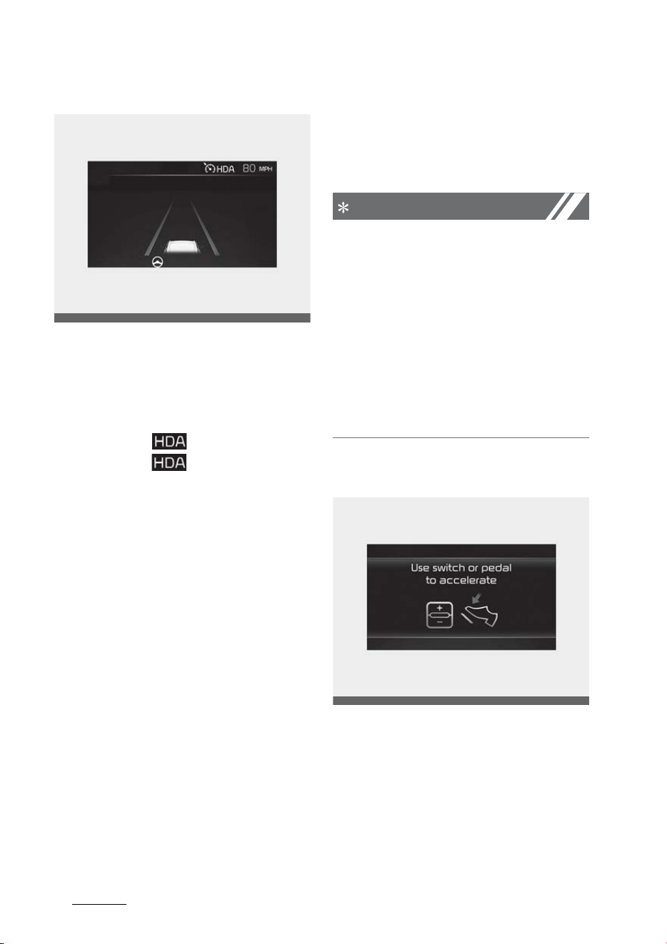
Driving your vehicle
1706
Highway Driving Assist (HDA)
Standby State
1. Highway Driving Assist indicator,
whether there is a vehicle ahead
and the selected distance level are
displayed.
䳜 Highway Driving Assist indicator
- Green ( ): Operating state
- White ( ): Standby state
2. Set speed is displayed.
3. Lane Following Assist indicator
displayed.
4. Whether there is a vehicle ahead
and the target vehicle to vehicle
distance are displayed.
5. Whether the lane is detected or
not is displayed.
For more details on the display refer
to "Smart Cruise Control (SCC) (if
equipped)" on page 6-139 and "Lane
Following Assist (LFA)" on page 6-
163.
Highway Driving Assist operating
Highway Driving Assist will operate
when entering or driving on the
main road of highways (or motor
-
ways), and satisfying all the follow
-
ing conditions:
䳜 Lane Following Assist is operating
䳜 Smart Cruise Control is operating
NOTICE
䳜 While driving on the highway (or
motorway), if Smart Cruise Con
-
trol starts operating, Highway
Driving Assist will operate.
䳜 When entering the main roads of
highways (or motorways), High
-
way Driving Assist will not turn on
if the Lane Following Assist is
turned off even when Smart
Cruise Control is operating.
Restarting after stopping
When Highway Driving Assist is
operating, your vehicle will stop if
the vehicle ahead of you stops. Also,
if the vehicle ahead of you starts
moving approximately within 30
seconds after the stop, your vehicle
will start as well. In addition, after
the vehicle has stopped and approx
-
OMQ4A050237
OMQ4050288L
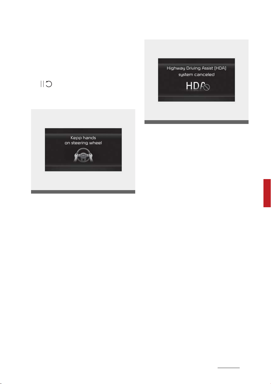
171
6
6
Driving your vehicle Highway Driving Assist (HDA)
imately 30 seconds have passed,
the 'Use switch or pedal to acceler
-
ate' message will appear on the
cluster. Depress the accelerator
pedal or push the + switch, - switch
or ( ) switch to start driving.
Hands-off warning
If the driver takes their hands off
the steering wheel for several sec
-
onds, the 'Keep hands on steering
wheel' warning message will appear
and an audible warning will sound in
stages.
䳜 First stage: Warning message
䳜 Second stage: Warning message
(red steering wheel) and audible
warning
If the driver still does not have their
hands on the steering wheel after
the hands-off warning, the 'High
-
way Driving Assist (HDA) canceled'
warning message will appear.
Highway Driving Assist standby
When the Smart Cruise Control is
temporarily canceled while Highway
Driving Assist is operating, Highway
Driving Assist will be in the standby
state. At this time, Lane Following
Assist will operate normally.
OMQ4051155L
OMQ4PH051395L
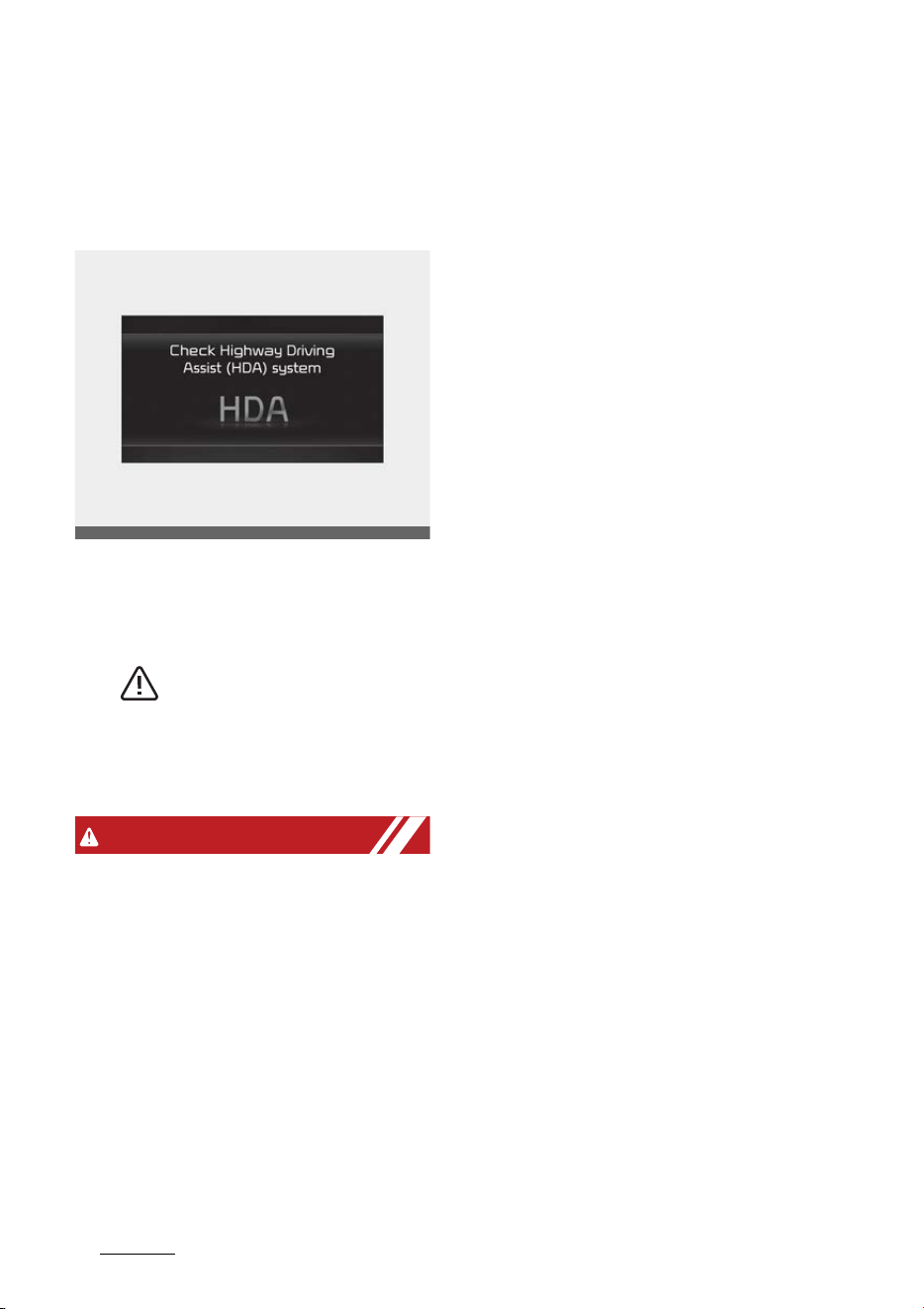
Driving your vehicle
1726
Highway Driving Assist (HDA)
Highway Driving Assist Malfunction
and Limitations
Highway Driving Assist malfunction
When Highway Driving Assist is not
working properly, the 'Check High
-
way Driving Assist (HDA) system'
warning message will appear, and
the ( ) warning light will illumi
-
nate on the cluster. Have the func
-
tion be inspected by an authorized
Kia dealer.
WARNING
䳜 The driver is responsible for con
-
trolling the vehicle for safe driv
-
ing.
䳜 Always have your hands on the
steering wheel while driving.
䳜 Highway Driving Assist is a sup
-
plemental function that assists
the driver in driving the vehicle
and is not a complete autono
-
mous driving system. Always
check road conditions, and if nec
-
essary, take appropriate actions
to drive safely.
䳜 Always have your eyes on the
road, and it is the responsibility of
the driver to avoid violating traffic
laws. The vehicle manufacturer is
not responsible for any traffic
violation or accidents caused by
the driver.
䳜 Highway Driving Assist may not
be able to recognize all traffic sit
-
uations. The function may not
detect possible collisions due to
Limitations. Always be aware of
the Limitations. Obstacles such as
vehicles, motorcycles, bicycles,
pedestrians, guardrails, toll gate,
unspecified objects, structures,
etc. that may collide with the
vehicle may not be detected.
䳜 Highway Driving Assist will turn
off automatically under the fol
-
lowing situations:
- Driving on roads that the func
-
tion does not operate, such as a
rest area, intersection, junc
-
tion, etc.
- The navigation does not oper
-
ate properly such as when the
navigation is being updated or
restarted
䳜 Highway Driving Assist may inad
-
vertently operate or turn off
depending on road conditions
(navigation information) and sur
-
roundings.
䳜 Lane Following Assist function
may be temporarily disabled
OMQ4050220L

173
6
6
Driving your vehicle Highway Driving Assist (HDA)
when the front view camera can
-
not detect lanes properly or the
hands-off warning is on.
䳜 You may not hear the warning
sound of Highway Driving Assist if
the surrounding is noisy.
䳜 If the vehicle is driven at high
speed above a certain speed at a
curve, your vehicle may drive to
one side or may depart from the
driving lane.
䳜 When you are towing a trailer or
another vehicle, we recommend
that Highway Driving Assist is
turned off due to safety reasons.
䳜 The hands䳍off warning message
may appear early or late depend
-
ing on how the steering wheel is
held or road conditions. Always
have your hands on the steering
wheel while driving.
䳜 For your safety, please read the
owner's manual before using the
Highway Driving Assist.
䳜 Highway Driving Assist will not
operate when the engine is
started, or when the detecting
sensors or navigation is being ini
-
tialized.
Limitations of Highway Driving
Assist
Highway Driving Assist and Highway
Lane Change function may not
operate normally, or may not oper
-
ate under the following circum
-
stances:
䳜 The map information and the
actual road is different because
the navigation is not updated
䳜 The map information and the
actual road is different because of
real-time GPS data or map infor
-
mation error
䳜 The infotainment system is over
-
loaded by simultaneously per
-
forming functions such as route
search, video playback, voice rec
-
ognition, etc.
䳜 GPS signals are blocked in areas
such as a tunnel
䳜 The driver goes off course or the
route to the destination is
changed or canceled by resetting
the navigation (including TPEG
change)
䳜 The vehicle enters a service sta
-
tion or rest area
䳜 Android Auto or Car Play is oper
-
ating
䳜 The navigation cannot detect the
current vehicle position (ex: ele
-
vated roads including overpass
adjacent to general roads or
nearby roads exist in a parallel
way)
CAUTION
For more details on the limitations
of the front view camera and front
radar, refer to "Forward Collision-
Avoidance Assist (FCA) (Sensor
fusion) (if equipped)" on page 6-73.
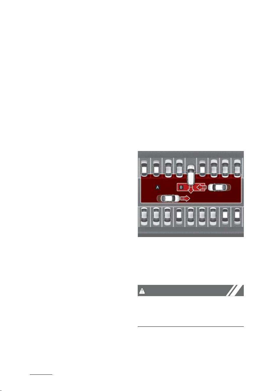
Driving your vehicle
1746
Rear Cross-Traffic Collision-Avoidance Assist
(RCCA)
This device complies with Part 15
of the FCC rules.
Operation is subject to the following
three conditions:
1. This device may not cause harm
-
ful interference.
2. This device must accept any
interference received, including
interference that may cause
undesired operation.
3. Changes or modifications not
expressly approved by the party
responsible for compliance could
void the user's authority to oper
-
ate the device.
Radio frequency radiation exposure
information:
This equipment complies with FCC
radiation exposure limits set forth
for an uncontrolled environment.
This equipment should be installed
and operated with minimum dis
-
tance of 8 in (20 cm) between the
radiator (antenna) and your body.
This transmitter must not be colo
-
cated or operating in conjunction
with any other antenna or trans
-
mitter.
Rear Cross-Traffic Collision-
Avoidance Assist (RCCA) (if
equipped)
Rear Cross-Traffic Collision-Avoid
-
ance Assist is designed to help
detect vehicles approaching from
the left and right side while your
vehicle is reversing, and warn the
driver that a collision is imminent
with a warning message and an
audible warning. Also, braking is
assisted to help prevent collision.
[A]: Rear Cross-Traffic Collision
Warning operating range
[B]: Rear Cross-Traffic Collision-
Avoidance Assist operating range
CAUTION
The time of warning may vary
depending on vehicle speed of the
approaching vehicle.
OMQ4050263
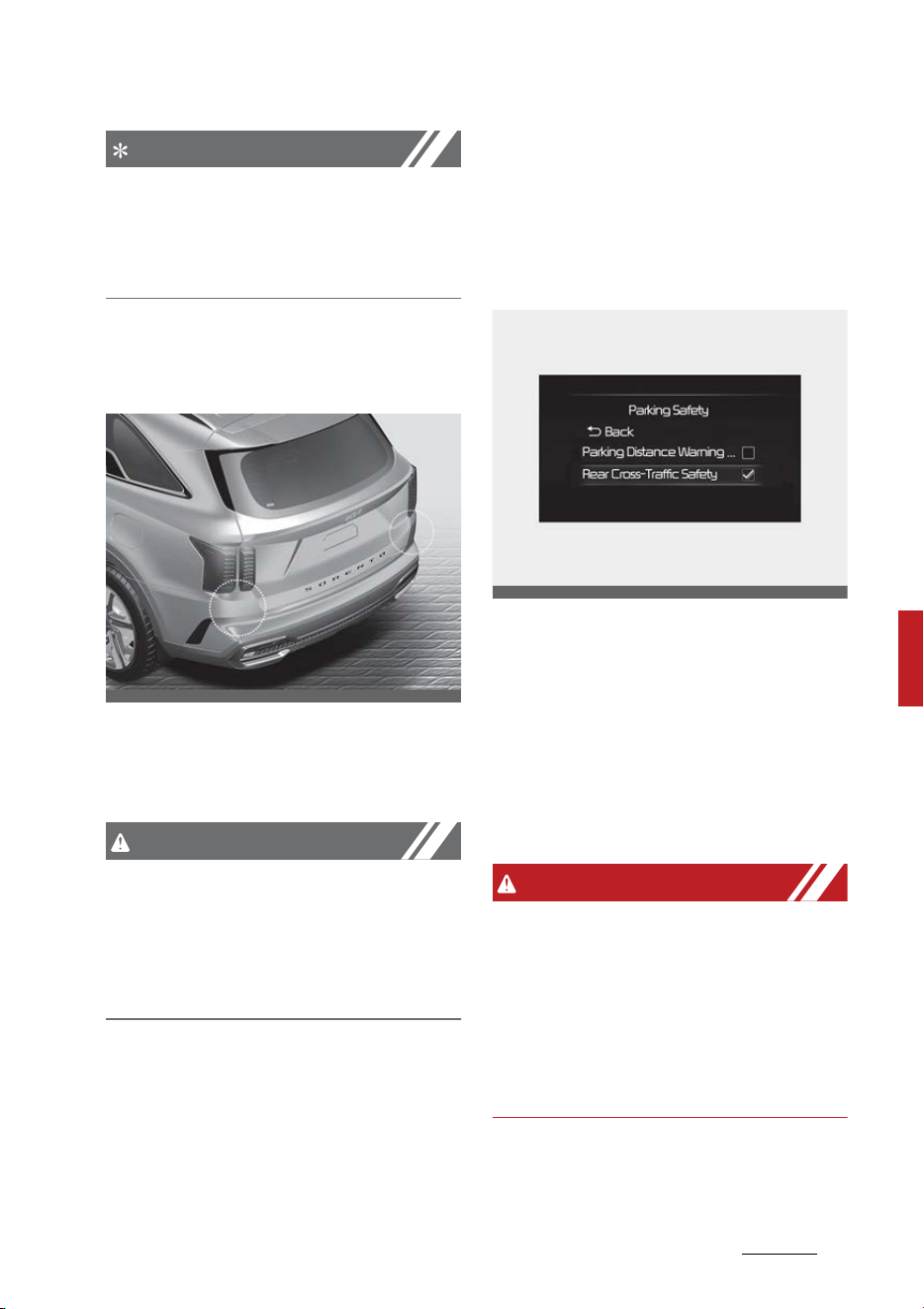
175
6
6
Driving your vehicle Rear Cross-Traffic Collision-Avoidance Assist
(RCCA)
NOTICE
In the following text, Rear Cross-
Traffic Collision Assist will be
referred as Rear Cross-Traffic Colli
-
sion-Avoidance Assist.
Detecting sensor
Rear corner radar
Refer to the picture above for the
detailed location of the detecting
sensor.
CAUTION
For more details on the precautions
of the rear corner radar, refer to
"Blind-Spot Collision-Avoidance
Assist (BCA) (if equipped)" on page
6-95.
Rear Cross-Traffic Collision- Avoid
-
ance Assist Settings
Setting
Rear Cross-Traffic Safety
With the ENGINE START/STOP but
-
ton in the ON position, select 'Driver
Assistance → Parking Safety →
Rear Cross-Traffic Safety' from the
Settings menu to turn on Rear
Cross-Traffic Collision-Avoidance
Assist and deselect to turn off the
function.
WARNING
When the engine is restarted, Rear
Cross-Traffic Collision-Avoidance
Assist will always turn on. However,
if 'Off' is selected after the engine is
restarted, the driver should always
be aware of the surroundings and
drive safely.
OMQ4AH051330
OMQ4AH050341
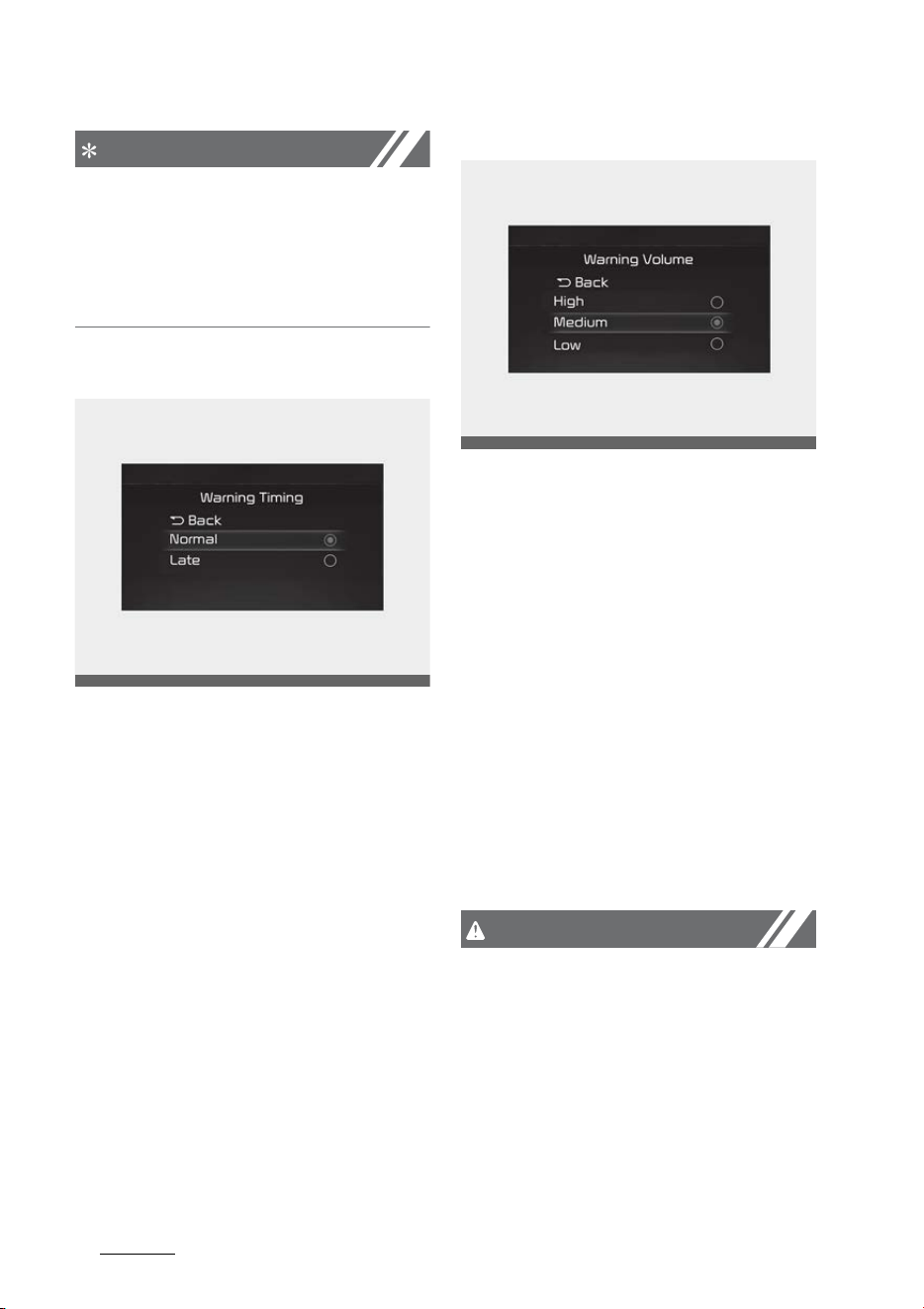
Driving your vehicle
1766
Rear Cross-Traffic Collision-Avoidance Assist
(RCCA)
NOTICE
Settings for Rear Cross-Traffic Colli
-
sion-Avoidance Assist include Rear
Cross-Traffic Collision Warning and
Rear Cross-Traffic Collision-Avoid
-
ance Assist.
Warning Timing
With the ENGINE START/STOP but
-
ton in the ON position, select 'Driver
Assistance → Warning Timing' from
the Settings menu to change the
initial warning activation time for
Rear Cross-Traffic Collision-Avoid
-
ance Assist.
When the vehicle is first delivered,
Warning Timing is set to 'Normal'. If
you change the Warning Timing, the
warning time of other Driver Assis
-
tance systems may change.
Warning Volume
With the ENGINE START/STOP but
-
ton in the ON position, select 'Driver
Assistance → Warning Volume' from
the Settings menu to change the
Warning Volume to 'High', 'Medium',
'Low' or 'Off' for Rear Cross-Traffic
Collision-Avoidance Assist.
However, when Warning Volume is
turned off, the steering wheel
vibration function will turn on if it
was turned off.
If you change the Warning Volume,
the Warning Volume of other Driver
Assistance systems may change.
CAUTION
䳜 The setting of the Warning Timing
and Warning Volume applies to all
functions of the Rear Collision-
Avoidance Assist.
䳜 Even though 'Normal' is selected
for Warning Timing, if the vehicles
from the left and right side
approaches at high speed, the ini
-
OMQ4AH050334
OMQ4041606
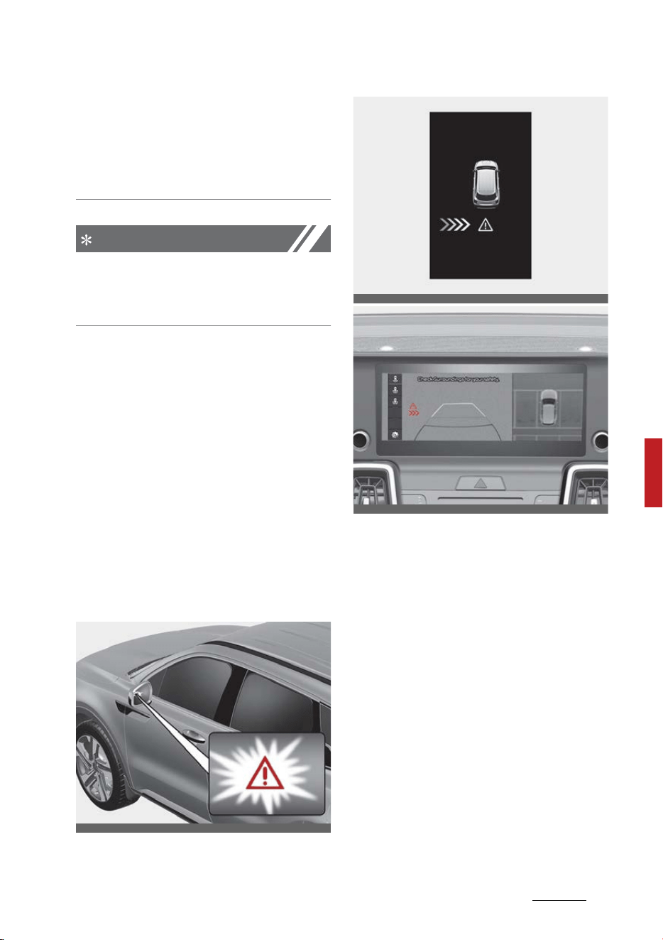
177
6
6
Driving your vehicle Rear Cross-Traffic Collision-Avoidance Assist
(RCCA)
tial warning activation time may
seem late.
䳜 Select 'Late' for Warning Timing
when traffic is light and when
driving speed is slow.
NOTICE
If the engine is restarted, Warning
Timing and Warning Volume will
maintain the last setting.
Rear Cross-Traffic Collision- Avoid
-
ance Assist Operation
Warning and control
Rear Cross-Traffic Collision-Avoid
-
ance Assist will warn and control the
vehicle depending on collision level:
'Collision Warning', 'Emergency
Braking' and 'Stopping vehicle and
ending brake control'.
Collision Warning
䳜 To warn the driver of an
approaching vehicle from the rear
left/right side of your vehicle, the
warning light on the side view
mirror will blink and a warning will
appear on the cluster. At the
same time, an audible warning will
sound and the steering wheel will
vibrate. If the Rear View Monitor
is operating, a warning will also
appear on the infotainment sys
-
tem screen.
䳜 The function will operate when all
the following conditions are satis
-
fied:
- The gear is changed to R
(Reverse)
OMQ4AH050098
OMQ4050309L
OMQ4AH050162
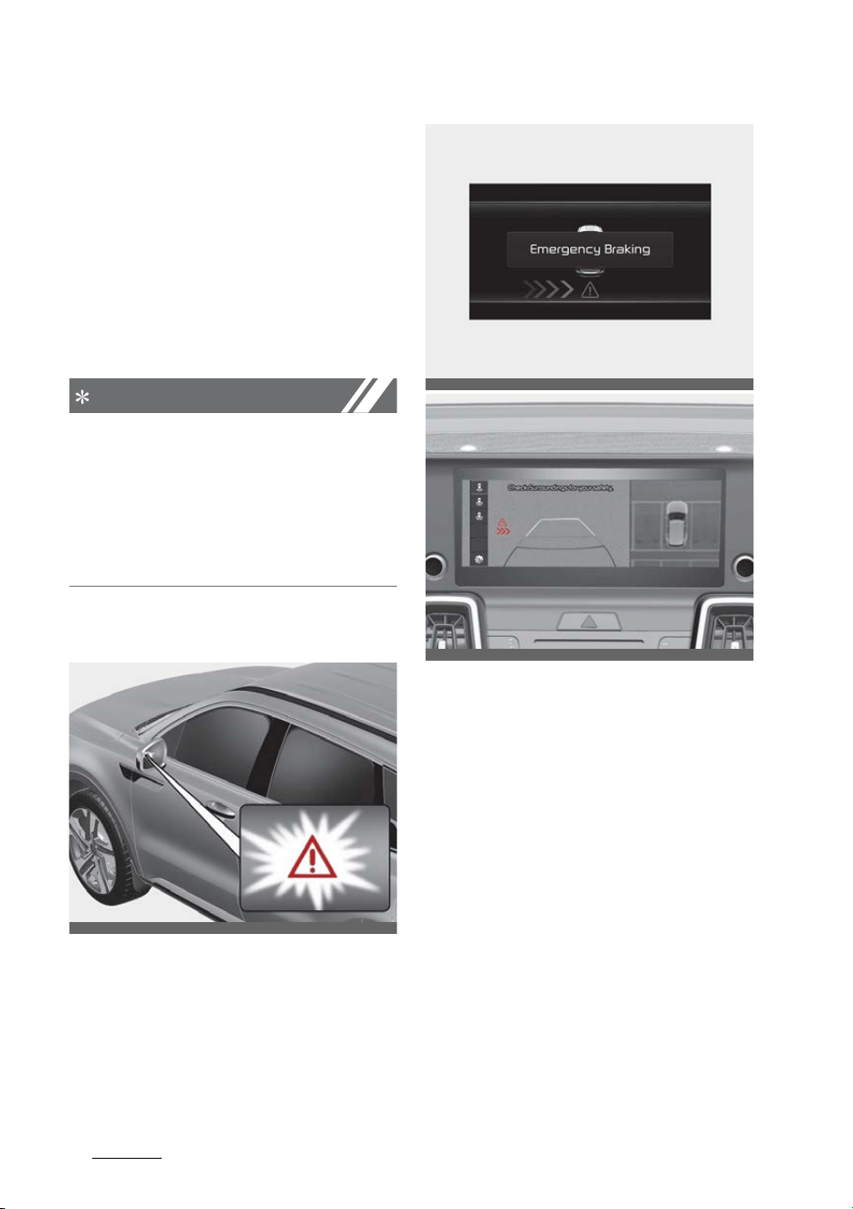
Driving your vehicle
1786
Rear Cross-Traffic Collision-Avoidance Assist
(RCCA)
- Vehicle speed is below 7.5mph
(12kph)
- The approaching vehicle is
within approximately 82 ft. (25
m) from the left and right side
of your vehicle
- The speed of the vehicle
approaching from the left and
right is above 3 mph (5 km/h)
NOTICE
If the operating conditions are satis
-
fied, there will be a warning when
-
ever the vehicle approaches from
the left or right side even though
your vehicle speed is 0 mph (0 km/
h).
Emergency Braking
䳜 To warn the driver of an
approaching vehicle from the rear
left/right side of your vehicle, the
warning light on the side view
mirror will blink and a warning
message will appear on the clus
-
ter. At the same time, an audible
warning will sound and the steer
-
ing wheel will vibrate. If the Rear
View Monitor is operating, a
warning will also appear on the
infotainment system screen.
䳜 The function will operate when all
the following conditions are satis
-
fied:
- The gear is changed to R
(Reverse)
OMQ4AH050098
OMQ4051289L
OMQ4AH050162
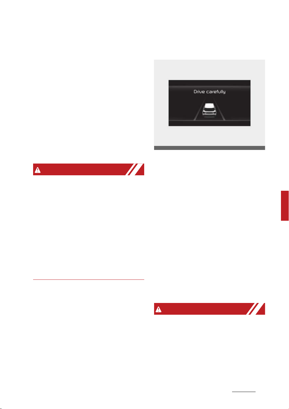
179
6
6
Driving your vehicle Rear Cross-Traffic Collision-Avoidance Assist
(RCCA)
- Vehicle speed is below 7.5mph
(12kph)
- The approaching vehicle is
within approximately 5 ft. (1.5
m) from the left and right side
of your vehicle
- The speed of the vehicle
approaching from the left and
right is above 3 mph (5 km/h)
䳜 Emergency braking will be
assisted to help prevent collision
with approaching vehicles from
the left and right.
WARNING
Brake control will end when:
䳜 The approaching vehicle is out of
the detecting range
䳜 The approaching vehicle passes
behind your vehicle
䳜 The approaching vehicle does not
drive toward your vehicle
䳜 The approaching vehicle speed
slows down
䳜 The driver depresses the brake
pedal with sufficient power
Stopping vehicle and ending brake
control
䳜 When the vehicle is stopped due
to emergency braking, the 'Drive
carefully' warning message will
appear on the cluster.
䳜 For your safety, the driver should
depress the brake pedal immedi
-
ately and check the surroundings.
䳜 Brake control will end after the
vehicle is stopped by emergency
braking for approximately 2 sec
-
onds.
䳜 During emergency braking, brak
-
ing control by the function will
automatically cancel when the
driver excessively depresses the
brake pedal.
WARNING
Take the following precautions
when using Rear Cross-Traffic Colli
-
sion-Avoidance Assist:
䳜 For your safety, change the Set
-
tings after parking the vehicle at a
safe location.
OMQ4040504L

Driving your vehicle
1806
Rear Cross-Traffic Collision-Avoidance Assist
(RCCA)
䳜 If any other function's warning
message is displayed or audible
warning is generated, Rear Cross-
Traffic Safety function's warning
message may not be displayed
and audible warning may not be
generated.
䳜 You may not hear the warning
sound of Rear Cross-Traffic Colli
-
sion-Avoidance Assist if the sur
-
rounding is noisy.
䳜 Rear Cross-Traffic Collision-
Avoidance Assist may not operate
if the driver applies the brake
pedal to avoid collision.
䳜 During Rear Cross-Traffic Safety
Function Operation, the vehicle
may stop suddenly injuring pas
-
sengers and shifting loose
objects. Always have the seat belt
on and keep loose objects
secured.
䳜 Even if there is a problem with
Rear Cross-Traffic Collision-
Avoidance Assist, the vehicle's
basic braking performance will
operate normally.
䳜 Rear Cross-Traffic Collision-
Avoidance Assist may warn the
driver late or may not warn the
driver depending on the road and
driving conditions.
䳜 Rear Cross-Traffic Collision-
Avoidance Assist does not operate
in all situations or cannot avoid all
collisions.
䳜 During emergency braking, brak
-
ing control by the function will
automatically cancel when the
driver excessively depresses the
accelerator pedal.
䳜 The driver should hold the
responsibility to control the vehi
-
cle. Do not solely depend on Rear
Cross-Traffic Collision-Avoidance
Assist. Rather, maintain a safe
braking distance, and if neces
-
sary, depress the brake pedal to
reduce driving speed or to stop
the vehicle.
䳜 Never deliberately operate Rear
Cross-Traffic Collision-Avoidance
Assist on people, animal, objects,
etc. It may cause serious injury or
death.
CAUTION
The brake control may not operate
properly depending on the status of
ESC (Electronic Stability Control).
There will only be a warning when:
䳜 The ESC (Electronic Stability Con
-
trol) warning light is on
䳜 ESC (Electronic Stability Control) is
engaged in a different function
NOTICE
䳜 If the function assists you with
braking, the driver must immedi
-
ately depress the brake pedal and
check vehicle surroundings.
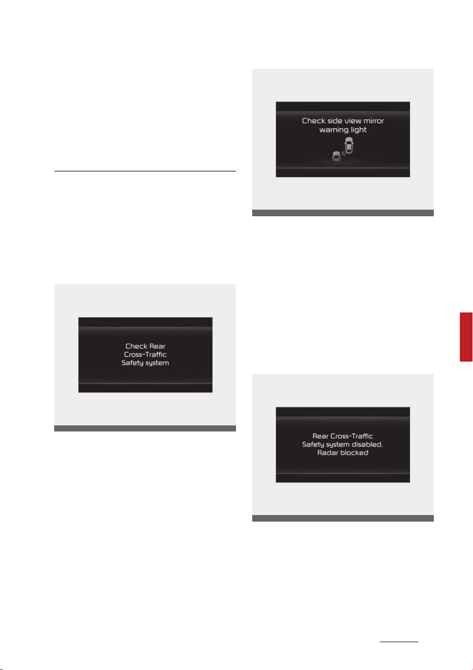
181
6
6
Driving your vehicle Rear Cross-Traffic Collision-Avoidance Assist
(RCCA)
- Brake control will end when the
driver depresses the brake
pedal with sufficient power.
- After changing the gear to R
(Reverse), braking control will
operate once for left and right
vehicle approach.
Rear Cross-Traffic Collision- Avoid
-
ance Assist Malfunction and Lim
-
itations
Rear Cross-Traffic Collision- Avoid
-
ance Assist malfunction
When Rear Cross-Traffic Collision-
Avoidance Assist is not working
properly, the 'Check Rear Cross-
Traffic Safety system' warning
message will appear on the cluster,
and the function will turn off auto
-
matically or the function will be lim
-
ited. Have the function be inspected
by an authorized Kia dealer.
When the side view mirror warning
light is not working properly, the
'Check side view mirror warning
light' warning message will appear
on the cluster. Have the function be
inspected by an authorized Kia
dealer.
Rear Cross-Traffic Collision- Avoid
-
ance Assist disabled
When the rear bumper around the
rear corner radar or rear sensor is
covered with foreign material, such
as snow or rain, or installing a trailer
or carrier, it can reduce the detect
-
ing performance and temporarily
OMQ4050290L
OMQ4050291L
OMQ4050292L

Driving your vehicle
1826
Rear Cross-Traffic Collision-Avoidance Assist
(RCCA)
limit or disable Rear Cross-Traffic
Collision-Avoidance Assist.
If this occurs, the 'Rear Cross-Traf
-
fic Safety Function disabled. Radar
blocked' warning message will
appear on the cluster.
The function will operate normally
when such foreign material or
trailer, etc. is removed.
If the function does not operate
normally after it is removed, have
the function be inspected by an
authorized Kia dealer.
WARNING
䳜 Even though the warning mes
-
sage does not appear on the clus
-
ter, Rear Cross-Traffic Collision-
Avoidance Assist may not operate
properly.
䳜 Rear Cross-Traffic Collision-
Avoidance Assist may not operate
properly in an area (for example:
open terrain), where any sub
-
stance are not detected after
turning ON the engine.
CAUTION
Turn off Rear Cross-Traffic Colli
-
sion-Avoidance Assist to install a
trailer, carrier, etc., or remove the
trailer, carrier, etc. to use Rear
Cross-Traffic Collision-Avoidance
Assist.
Limitations of Rear Cross-Traffic
Collision-Avoidance Assist
Rear Cross-Traffic Collision-Avoid
-
ance Assist may not operate nor
-
mally, or the function may operate
unexpectedly under the following
circumstances:
䳜 Departing from where trees or
grass are overgrown
䳜 Departing from where roads are
wet
䳜 Speed of the approaching vehicle
is fast or slow
Braking control may not work,
driver's attention is required in the
following circumstances:
䳜 The vehicle severely vibrates
while driving over a bumpy road,
uneven road or concrete patch
䳜 Driving on a slippery surface due
to snow, water puddle, ice, etc.
䳜 The tire pressure is low or a tire is
damaged
䳜 The brake is reworked
CAUTION
For more details on the limitations
of the rear corner radar, refer to
"Blind-Spot Collision-Avoidance
Assist (BCA) (if equipped)" on page
6-95.
WARNING
䳜 Driving near a vehicle or structure
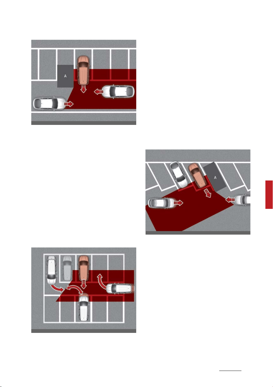
183
6
6
Driving your vehicle Rear Cross-Traffic Collision-Avoidance Assist
(RCCA)
[A]: Structure
Rear Cross-Traffic Collision-
Avoidance Assist may be limited
when driving near a vehicle or
structure, and may not detect the
vehicle approaching from the left
or right. If this occurs, the func
-
tion may not warn the driver or
control the brakes when neces
-
sary.
Always check your surroundings
while backing up.
䳜 When the vehicle is in a complex
parking environment
Rear Cross-Traffic Collision-
Avoidance Assist may detect
vehicles which are parking or pull
-
ing out near your vehicle (for
example: a vehicle leaving beside
your vehicle, a vehicle parking or
pulling out in the rear area, a vehi
-
cle approaching your vehicle mak
-
ing a turn, etc.). If this occurs, the
function may unnecessarily warn
the driver and control the brake.
Always check your surroundings
while backing up.
䳜 When the vehicle is parked diago
-
nally
[A]: Vehicle
Rear Cross-Traffic Collision-
Avoidance Assist may be limited
when backing up diagonally, and
may not detect the vehicle
approaching from the left or
right. If this occurs, the function
may not warn the driver or con
-
trol the brakes when necessary.
Always check your surroundings
while backing up.
䳜 When the vehicle is on or near a
slope
OMQ4050170
OMQ4050171
OMQ4050172
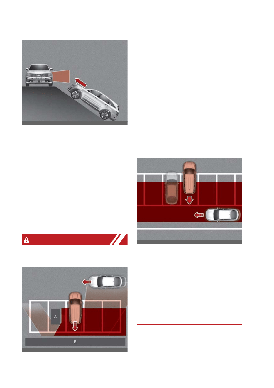
Driving your vehicle
1846
Rear Cross-Traffic Collision-Avoidance Assist
(RCCA)
Rear Cross-Traffic Collision-
Avoidance Assist may be limited
when the vehicle is on a uphill or
downhill slope, or near it, and may
not detect the vehicle approach
-
ing from the left or right. If this
occurs, the function may not
warn the driver or control the
brakes when necessary.
Always check your surroundings
while backing up.
WARNING
䳜 Pulling into the parking space
where there is a structure
[A]: Structure, [B]: Wall
Rear Cross-Traffic Collision-
Avoidance Assist may detect
vehicles passing by in front of you
when parking backwards into a
parking space with a wall or
structure in the rear or side area.
If this occurs, the function may
unnecessarily warn the driver and
control the brake.
Always check your surroundings
while backing up.
䳜 When the vehicle is parked rear
-
ward
Rear Cross-Traffic Collision-
Avoidance Assist may detect
vehicles passing by behind you
when parking backwards into a
parking space. If this occurs, the
function may unnecessarily warn
the driver and control the brake.
Always check your surroundings
while backing up.
OMQ4H051033
OMQ4050173
OMQ4050174
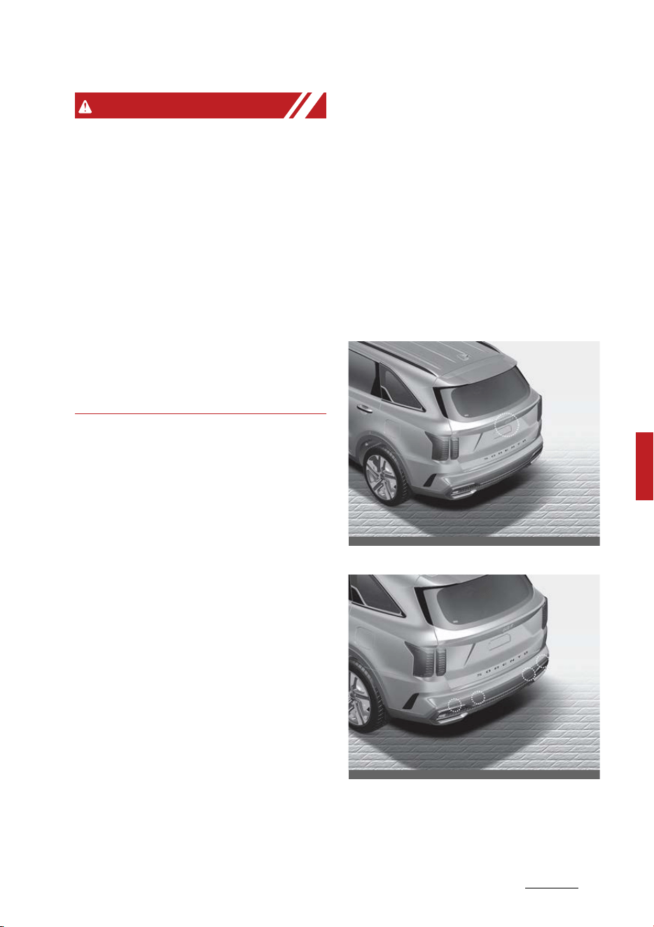
185
6
6
Driving your vehicle Reverse Parking Collision-Avoidance Assist (PCA)
WARNING
䳜 When you are towing a trailer or
another vehicle, we recommend
that Rear Cross-Traffic Collision-
Avoidance Assist is turned off due
to safety reasons.
䳜 Rear Cross-Traffic Collision-
Avoidance Assist may not operate
normally if interfered by strong
electromagnetic waves.
䳜 Rear Cross-Traffic Collision-
Avoidance Assist may not operate
for approximately 3 seconds after
the vehicle is started, or the rear
corner radars are initialized.
This device complies with Part 15
of the FCC rules.
Operation is subject to the following
two conditions:
1. This device may not cause harm
-
ful interference.
2. This device must accept any
interference received, including
interference that may cause
undesired operation.
Reverse Parking Collision-Avoid
-
ance Assist (PCA) (if equipped)
Reverse Parking Collision-Avoidance
Assist may warn the driver or may
assist with braking to help reduce
the possibility of collision with a
pedestrian or an object when back
-
ing up.
Detecting sensor
Rear view camera
Rear ultrasonic sensors
Refer to the picture above for the
detailed location of the detecting
sensors.
OMQ4AH041564
OMQ4AH041566
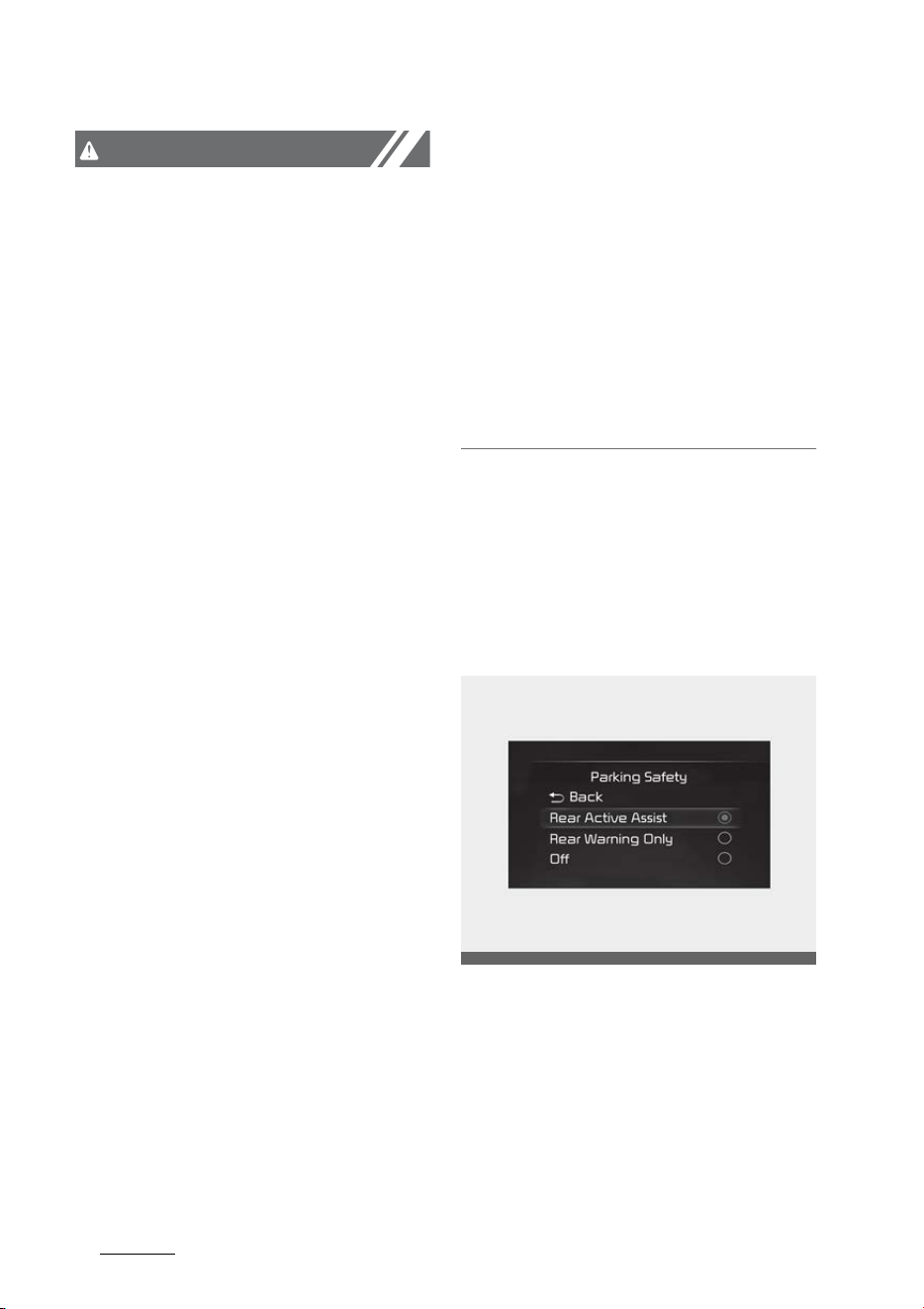
Driving your vehicle
1866
Reverse Parking Collision-Avoidance Assist (PCA)
CAUTION
Take the following precautions to
maintain optimal performance of
the detecting sensors:
䳜 Always keep the rear view camera
and rear ultrasonic sensors clean.
䳜 Do not use any cleanser contain
-
ing acid or alkaline detergents
when cleaning the rear view cam
-
era lens. Use only a mild soap or
neutral detergent, and rinse thor
-
oughly with water.
䳜 Never disassemble or apply
impact on the rear view camera
or the rear ultrasonic sensors
components.
䳜 Do not apply unnecessary force
on the rear view camera or the
rear ultrasonic sensors. Reverse
Parking Collision-Avoidance Assist
may not operate properly if the
rear view camera or the rear
ultrasonic sensor(s) is forcibly
moved out of proper alignment.
Have the vehicle inspected by an
authorized Kia dealer.
䳜 Do not spray the rear view cam
-
era or the rear ultrasonic sensors
or their surrounding area directly
with a high pressure washer. It
may cause the rear view camera
or the rear ultrasonic sensors to
malfunction.
䳜 Reverse Parking Collision-Avoid
-
ance Assist may not work prop
-
erly if the bumper has been
damaged, replaced or repaired.
䳜 Do not apply objects, such as a
bumper sticker or a bumper guard,
near the rear view camera or rear
ultrasonic sensors or apply paint to
the bumper. Doing so may adversely
affect the performance of Reverse
Parking Collision-Avoidance Assist.
䳜 Reverse Parking Collision-Avoid
-
ance Assist may not operate nor
-
mally if interfered by strong
electromagnetic waves.
Reverse Parking Distance Warning
Settings
Setting
Parking Safety
With the ENGINE START/STOP but
-
ton in the ON position, select or
deselect 'Driver Assistance → Park
-
ing Safety' from the Settings menu
to set whether or not to use each
function.
䳜 If 'Rear Active Assist' is selected,
the function will warn the driver
OMQ4AH050348
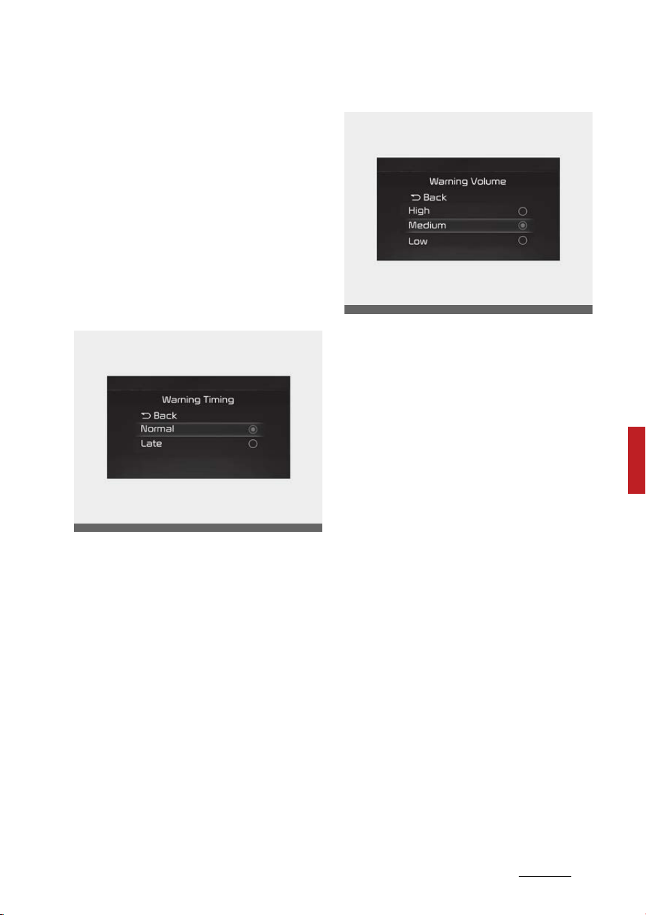
187
6
6
Driving your vehicle Reverse Parking Collision-Avoidance Assist (PCA)
and assist with braking when a
collision with a pedestrian or an
object is imminent.
䳜 If 'Rear Warning Only' is selected,
the function will warn the driver
when a collision with a pedestrian
or an object is imminent. Braking
will not be assisted.
䳜 If 'Off' is selected, the function will
turn off.
Warning Timing
With the ENGINE START/STOP but
-
ton in the ON position, select 'Driver
Assistance → Warning Timing' from
the Settings menu to change the
initial warning activation time for
Forward Collision-Avoidance Assist.
When the vehicle is first delivered,
Warning Timing is set to 'Normal'.
If you change the Warning Timing,
the warning time of other Driver
Assistance systems may change.
Warning Volume
With the ENGINE START/STOP but
-
ton in the ON position, select 'Driver
Assistance → Warning Volume' from
the Settings menu to change the
Warning Volume to 'High', 'Medium',
'Low' of 'Off' for Forward Collision-
Avoidance Assist.
However, when Warning Volume is
turned off, the steering wheel
vibration function will turn on if it
was turned off.
If you change the Warning Volume,
the Warning Volume of other Driver
Assistance systems may change.
Reverse Parking Distance Warning
Operation
Operating conditions
If 'Rear Active Assist' or 'Rear Warn
-
ing Only' is set from the Settings
menu, Reverse Parking Collision-
Avoidance Assist will be in the ready
status when the following condi
-
tions are satisfied:
OMQ4AH050334
OMQ4041606

Driving your vehicle
1886
Reverse Parking Collision-Avoidance Assist (PCA)
䳜 The liftgate is closed
䳜 The gear is changed to R
(Reverse)
䳜 Vehicle speed is below 7.5mph
(12kph)
System components such as the
rear view camera and the rear
ultrasonic sensors are in normal
conditions
Rear Warning Only
䳜 If the function detects a risk of
collision with a pedestrian or an
object, the function will warn the
driver with an audible warning,
steering wheel vibration and
warning message on the cluster.
When Rear View Monitor is oper
-
ating, a warning will appear on the
infotainment system screen.
䳜 If 'Rear Warning Only' is selected,
braking will not be assisted.
䳜 The warning will turn off when
the gear is shifted to P (Park), N
(Neutral) or D (Drive).
Rear Active Assist
䳜 If the function detects a risk of
collision with a pedestrian or an
object, Reverse Parking Collision-
Avoidance Assist will warn the
driver with an audible warning,
steering wheel vibration and
warning message on the cluster.
When Rear View Monitor system
is operating, a warning will appear
on the infotainment system
screen.
䳜 If the function detects imminent
collision with a pedestrian or an
object behind the vehicle, the
function will assist you with brak
-
ing. The driver needs to pay
attention as the brake assist will
end within 2 seconds. The driver
must immediately depress the
brake pedal and check vehicle sur
-
roundings.
䳜 Brake control will end when:
- The gear is changed to P (Park)
or D (Drive).
- The driver depresses the brake
pedal with sufficient power
- Braking assist last for approxi
-
mately 2 seconds
䳜 The warning will turn off when:
- The driver changes the gear to
P (Park), N (Neutral), or D
(Drive)
䳜 The brake control may not oper
-
ate properly depending on the
status of ESC (Electronic Stability
Control).
䳜 There will only be a warning
when:
- The ESC (Electronic Stability
Control) warning light is on
- ESC (Electronic Stability Con
-
trol) is engaged in a different
function
WARNING
䳜 Playing the vehicle audio system
at high volume may prevent pas
-
sengers from hearing Reverse
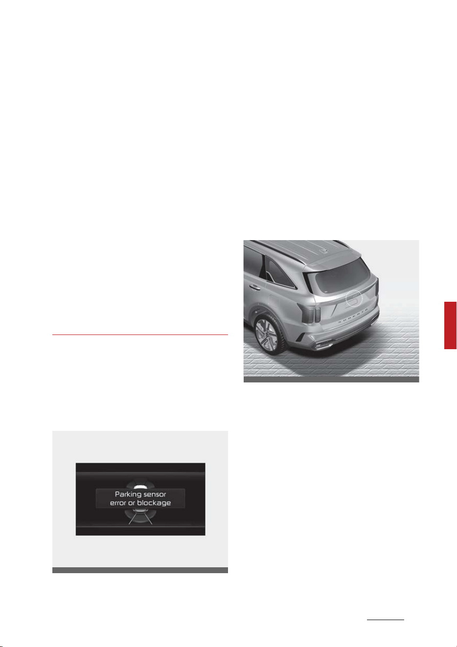
189
6
6
Driving your vehicle Reverse Parking Collision-Avoidance Assist (PCA)
Parking Collision-Avoidance Assist
warning sounds
䳜 Noise may be heard when sudden
braking occurs to avoid a collision.
䳜 If any other warning sound such
as the seat belt warning chime is
already generated, Reverse Park
-
ing Collision-Avoidance Assist
warning may not sound.
䳜 The performance of Reverse
Parking Collision-Avoidance Assist
may vary under certain condi
-
tions. If vehicle speed is above 2
mph (4 km/h), the function will
provide collision avoidance assist
only when pedestrians are
detected. Always look around and
pay attention when backing up
your vehicle.
Reverse Parking Distance Warning
Malfunction and Limitations
Reverse Parking Distance Warning
malfunction
When Reverse Parking Collision-
Avoidance Assist or other related
systems are not working properly,
the 'Check Parking Collision-Avoid
-
ance Assist system' warning mes
-
sage will appear on the cluster, and
the function will turn off automati
-
cally. Have your vehicle inspected by
an authorized Kia dealer.
Reverse Parking Distance Warning
disabled
The rear view camera is used as a
detecting sensor to detect pedestri
-
ans. If the camera lens is covered
with foreign material, such as snow
or rain, it may adversely affect
camera performance and Reverse
Parking Collision-Avoidance Assist
may not operate normally. Always
keep the camera lens clean.
OMQ4040510L
OMQ4AH041564
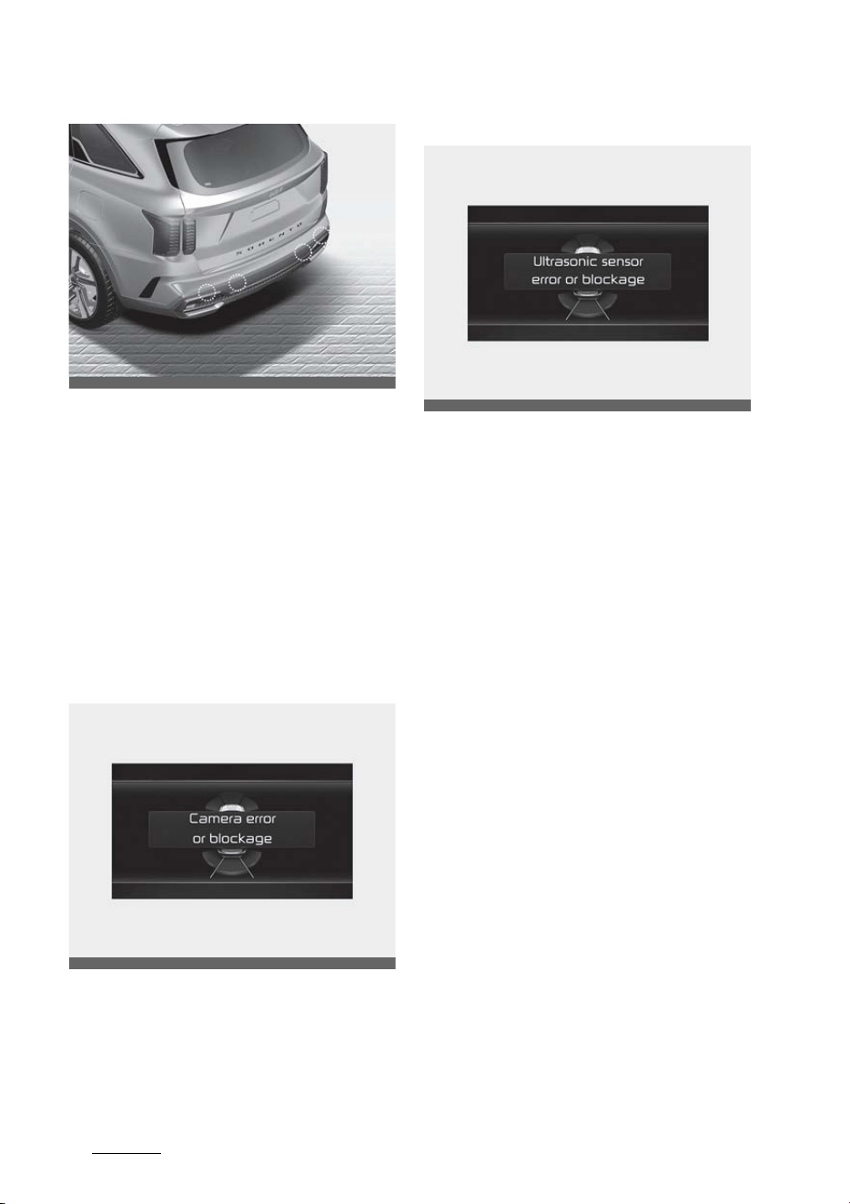
Driving your vehicle
1906
Reverse Parking Collision-Avoidance Assist (PCA)
The rear ultrasonic sensors are
located inside the rear bumper to
detect objects in the rear area. If
the sensors are covered with foreign
material, such as snow or rain, it
may adversely affect sensor per
-
formance and Reverse Parking Colli
-
sion-Avoidance Assist may not
operate normally. Always keep the
rear bumper clean.
Rear view camera
Rear ultrasonic sensor
The 'Camera error or blockage'
'Camera error or blockage' or 'Ultra
-
sonic sensor error of blockage'
warning message will appear on the
cluster if the following situations
occur:
䳜 The rear view camera or ultra
-
sonic sensors are covered with
foreign material, such as snow or
rain, etc.
䳜 There is inclement weather, such
as heavy snow, heavy rain, etc.
If this occurs, Reverse Parking Colli
-
sion-Avoidance Assist may turn off
or may not operate properly. Check
whether the rear view camera and
rear ultrasonic sensors are clean.
Limitations of Reverse Parking Dis
-
tance Warning
Reverse Parking Collision-Avoidance
Assist may not assist braking or
warn the driver even if there are
pedestrians or objects under the
following circumstances:
OMQ4AH041566
OMQ4PH051396L
OMQ4PH051397L

191
6
6
Driving your vehicle Reverse Parking Collision-Avoidance Assist (PCA)
䳜 Any non-factory equipment or
accessory is installed
䳜 Your vehicle is unstable due to an
accident or other causes
䳜 Bumper height or rear ultrasonic
sensor installation has been mod
-
ified
䳜 Rear view camera or rear ultra
-
sonic sensor(s) is damaged
䳜 Rear view camera or the rear
ultrasonic sensor(s) is stained
with foreign matter, such as
snow, dirt, etc.
䳜 Rear view camera is obscured by
a light source or by inclement
weather, such as heavy rain, fog,
snow, etc.
䳜 The surrounding is very bright or
very dark
䳜 Outside temperature is very high
or very low
䳜 The wind is either strong (above
12 mph (20 km/h)) or blowing
perpendicular to the rear bumper
䳜 Objects generating excessive
noise, such as vehicle horns, loud
motorcycle engines or truck air
brakes, are near your vehicle
䳜 An ultrasonic sensor with similar
frequency is near your vehicle
䳜 There is ground height difference
between the vehicle and the
pedestrian
䳜 The image of the pedestrian in
the rear view camera is indistin
-
guishable from the background
䳜 The pedestrian is near the rear
edge of the vehicle
䳜 The pedestrian is not standing
upright
䳜 The pedestrian is either very
short or very tall for the function
to detect
䳜 The pedestrian or cyclist is wear
-
ing clothing that easily blends into
the background, making it difficult
to detect
䳜 The pedestrian is wearing clothing
that does not reflect ultrasonic
waves well
䳜 Size, thickness, height, or shape
of the object does not reflect
ultrasonic waves well (e.g., pole,
bush, curbs, carts, edge of a wall,
etc.)
䳜 The pedestrian or the object is
moving
䳜 The pedestrian or the object is
very close to the rear of the vehi
-
cle
䳜 A wall is behind the pedestrian or
the object
䳜 The object is not located at the
rear center of your vehicle
䳜 The object is not parallel to the
rear bumper
䳜 The road is slippery or inclined
䳜 The driver backs up the vehicle
immediately after shifting to R
(Reverse)
䳜 The driver accelerates or circles
the vehicle
Reverse Parking Collision-Avoidance
Assist may unnecessarily warn the
driver or assist with braking even if
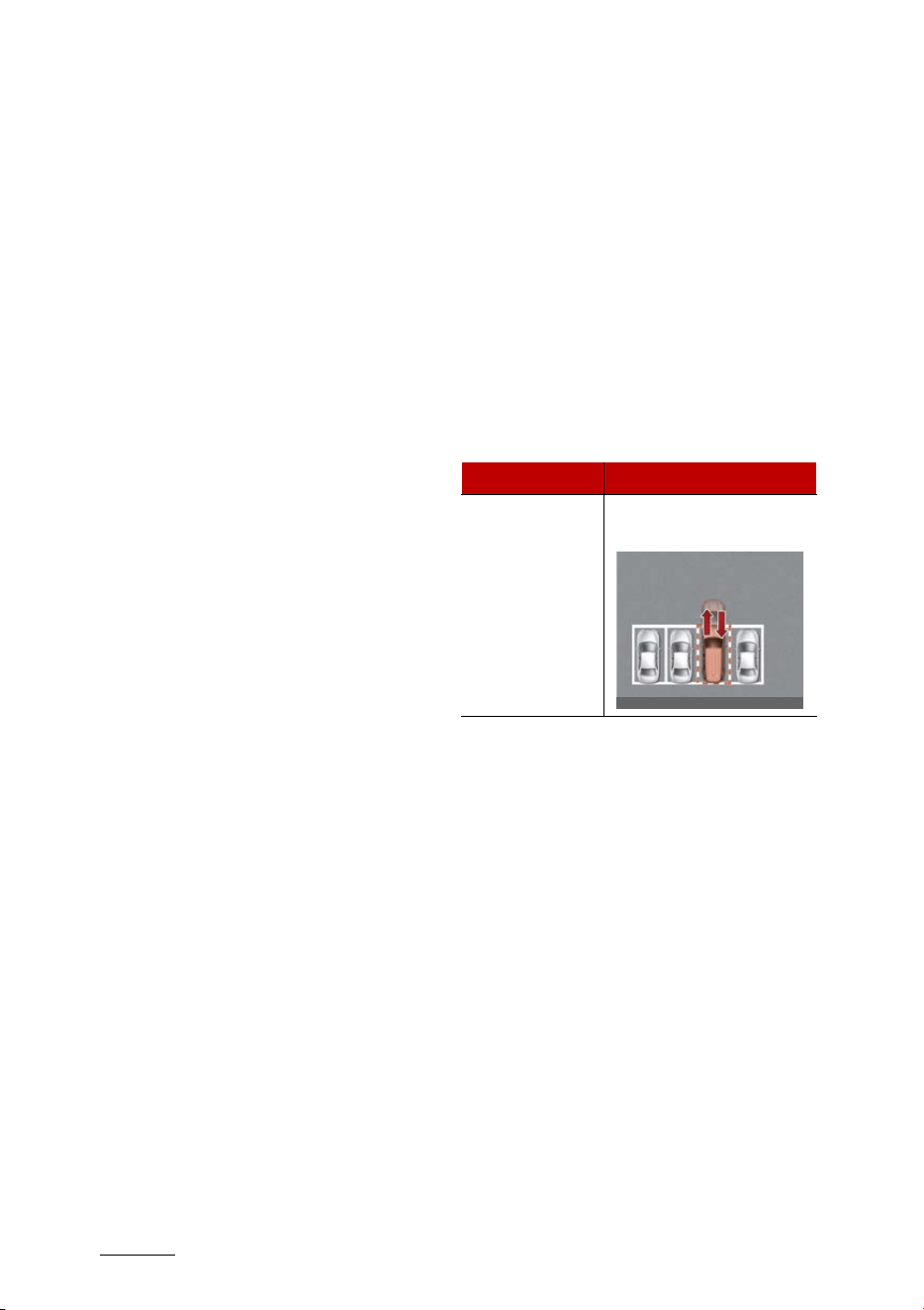
Driving your vehicle
1926
Remote Smart Parking Assist (RSPA)
there are no pedestrians or objects
under the following circumstances:
䳜 Any non-factory equipment or
accessory is installed
䳜 Your vehicle is unstable due to an
accident or other causes
䳜 Bumper height or rear ultrasonic
sensor installation has been mod
-
ified
䳜 Your vehicle height is low or high
due to heavy loads, abnormal tire
pressure, etc.
䳜 Rear view camera or the rear
ultrasonic sensor(s) is stained
with foreign matter, such as
snow, dirt, etc.
䳜 The pattern on the road is mis
-
taken for a pedestrian
䳜 There is shadow or light reflecting
on the ground
䳜 Pedestrians or objects are around
the path of the vehicle
䳜 Objects generating excessive
noise, such as vehicle horns, loud
motorcycle engines or truck air
brakes, are near your vehicle
䳜 Your vehicle is backing towards a
narrow passage or parking space
䳜 Your vehicle is backing towards an
uneven road surface, such as an
unpaved road, gravel, bump, gra
-
dient, etc.
䳜 A trailer or carrier is installed on
the rear of your vehicle
䳜 An ultrasonic sensor with similar
frequency is near your vehicle
Remote Smart Parking Assist
(RSPA) (if equipped)
Remote Smart Parking Assist uses
vehicle sensors to help the driver
park and exit parking spaces
remotely from outside the vehicle
by automatically searching for
parking spaces, and controlling the
steering wheel, vehicle speed and
gearshifts.
䳜 Remote Moving Forward/Back
-
ward function helps the driver
move the vehicle forward or back
-
ward from outside the vehicle
using the smart key.
䳜 When Remote Smart Parking
Assist operates, Surround View
Monitor and Parking Distance
Warning will also operate. For
more details, refer to "Surround
View Monitor (SVM) (if equipped)"
on page 4-114 and "Forward/
Reverse Parking Distance Warning
(PDW) (if equipped)" on page 4-
124.
Function Description
Remote Opera
-
tion
Remotely moving forward
or backward
OMQ4050176

193
6
6
Driving your vehicle Remote Smart Parking Assist (RSPA)
WARNING
䳜 The driver is responsible for safe
parking and exit when using
Remote Smart Parking Assist.
Make sure there are no pedestri
-
ans, animals or objects around the
vehicle when using the function.
䳜 Always check surroundings when
using Remote Smart Parking
Assist. You may collide with
pedestrians, animals, or objects if
they are near the sensor or are in
the sensor䳓s blind spot area.
䳜 A collision may occur if a pedes
-
trian, animal, or object suddenly
appears while Remote Smart
Parking Assist is operating.
䳜 Do not use Remote Smart Parking
Assist when under the influence
of alcohol.
䳜 Do not let children or other people
to use the smart key.
䳜 When operating Remote Smart
Parking Assist, be careful of
objects such as flower pots or
parking blocks located above or
below the ultrasonic sensor. Such
object may damage the vehicle or
other objects.
CAUTION
䳜 Remote Smart Parking Assist
may not operate properly
depending on the surroundings
and other conditions.
䳜 If the Remote Smart Parking
Assist is used continuously for a
long period, it may adversely
affect function performance.
䳜 Remote Smart Parking Assist
may not operate normally if the
vehicle needs wheel alignment
adjustment such as when the
vehicle tilts to one side. We rec
-
ommend that the vehicle be
checked by an authorized Kia
dealer/service partner.
䳜 If you use a different tire or wheel
size rather than the size recom
-
mended, it may adversely affect
Remote Smart Parking Assist
performance.
䳜 Remote Smart Parking Assist
performance may reduce on
uneven surfaces (curbstone,
speed bump, etc.).
䳜 If you attach objects or install any
types of cover on the steering
wheel, it may cancel Remote
Smart Parking Assist operation.
䳜 Noise may be heard when braking
occurs by Remote Smart Parking
Assist or when the brake pedal is
depressed by the driver.
䳜 Remote Smart Parking Assist
may suddenly apply the brake to
avoid collision.
䳜 Use the function only in a parking
space that is large enough for the
vehicle to move safely.
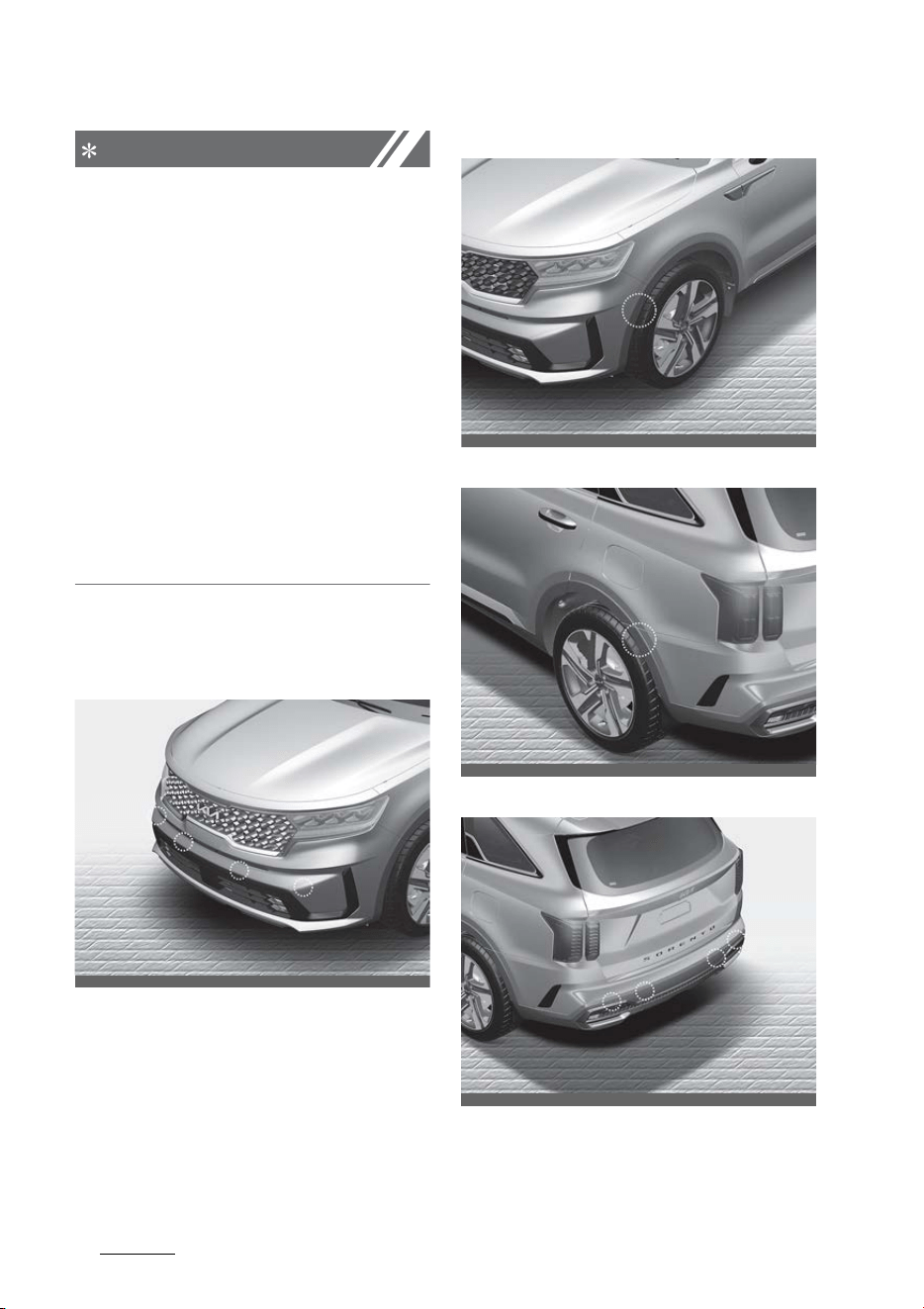
Driving your vehicle
1946
Remote Smart Parking Assist (RSPA)
NOTICE
䳜 If the 3rd stage warning (continu
-
ous beep) of the Forward/Reverse
Parking Distance Warning sounds
while Remote Smart Parking
Assist is operating, it means the
obstacle detected is close to your
vehicle. At this time, Remote
Smart Parking Assist will tempo
-
rarily stop operating. Make sure
there are no pedestrians, animals,
or objects around your vehicle.
䳜 Depending on brake operation,
the stop lights may come on while
the vehicle is moving.
Detecting sensor
Front ultrasonic sensors
Front corner ultrasonic sensors
Rear corner ultrasonic sensors
Rear ultrasonic sensors
Refer to the picture above for the
detailed location of the detecting
sensors.
OMQ4H041007
OMQ4040437L
OMQ4PH041601N
OMQ4AH041566

195
6
6
Driving your vehicle Remote Smart Parking Assist (RSPA)
CAUTION
Take the following precautions to
maintain optimal performance of
the detecting sensors:
䳜 Never disassemble the detecting
sensor or sensor assembly, or
apply any impact on it.
䳜 If the detecting sensor have been
replaced or repaired, we recom
-
mend that you have your vehicle
inspected by an authorized Kia
dealer/service partner.
䳜 Remote Smart Parking Assist
may not operate normally when:
- Moisture is frozen to the sensor
- Sensor is covered with foreign
material, such as snow or water
The function will operate normally
when such foreign material are
removed.
䳜 Remote Smart Parking Assist
may malfunction when:
- Driving on uneven road, gravel
roads or bushes
- Objects that generates ultra
-
sonic waves such as vehicle
horns, loud motorcycle engine
sound or truck air brakes are
near the sensor
- Heavy rain or water spray is
present
- Wireless transmitters or mobile
phones are present near the
sensor
- The sensor is covered with
snow
- Affected by another vehicle䳓s
sensors
- Water flows on the surface of
the sensor
- Installing the license plate dif
-
ferently from the original loca
-
tion
䳜 Detecting range may decrease
when:
- Sensor is covered with foreign
matters, such as snow or water
(The function will operate nor
-
mally when such foreign mate
-
rial are removed.)
- The weather is extremely hot
or cold
䳜 The following objects may not be
detected:
- Sharp or slim objects, such as
ropes, chains or small poles.
- Objects which tend to absorb
sensor frequency, such as
clothes, spongy material or
snow.
- Objects smaller than 100 cm
(40 in.) in length and narrower
than 14 cm (6 in.) in diameter.
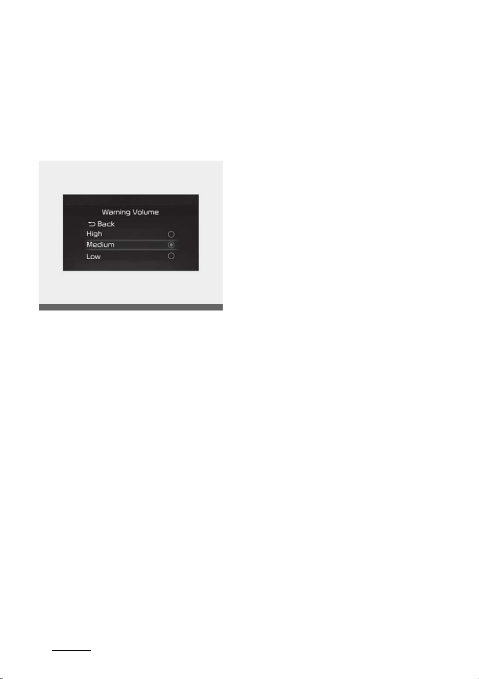
Driving your vehicle
1966
Remote Smart Parking Assist (RSPA)
Remote Smart Parking Assist Set
-
tings
Setting
Warning Volume
With the ENGINE START/STOP but
-
ton in the ON position, select 'Driver
Assistance → Warning Volume' from
the Settings menu to change the
Warning Volume to 'High', 'Medium',
'Low' or 'Off' for Remote Smart
Parking Assist.
However, even if 'Off' is selected,
the function's Warning Volume will
not turn off but the volume will
sound as 'Low'.
If you change the Warning Volume,
the Warning Volume of other Driver
Assistance systems may change.
OMQ4041606

197
6
6
Driving your vehicle Remote Smart Parking Assist (RSPA)
Remote Smart Parking button
Parking/View button
Smart key Remote Start and Forward/Backward
button
Location Name Symbol Description
Inside vehicle
Parking/View
button
Press and hold the Parking/View button to turn on
Remote Smart Parking Assist. Also, Forward/Reverse
Parking Distance warning will automatically turn on.
However, functions may differ depending on the situa
-
tions. Refer to each function's description for more details
in the following pages.
Parking Safety
button
Press the Parking Safety button while Remote Smart
Parking Assist is operating to end function operation.
Smart Key
Remote Start
button
Press the Remote Start button after the door is locked
with the engine off to start the engine remotely.
Press the Remote Start button while Remote Operation
function is operating to end function operation.
Forward button
When using the Remote Operation function, the vehicle
moves in the direction of the button while the button is
pressed.
Backward button
OMQ4040439
OMQ4PH041602N
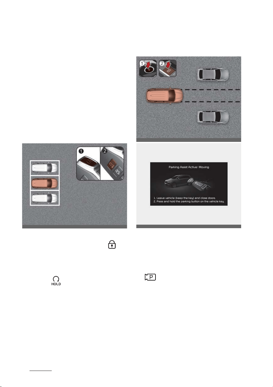
Driving your vehicle
1986
Remote Smart Parking Assist (RSPA)
Remote Smart Parking Assist
Operation
Remote Operation
1. Getting ready to remotely move
forward and backward
There are two ways to operate
Remote Operation.
Method (1): Using the function with
engine off
1. Within a certain range from the
vehicle press the door lock ( )
button on the smart key and lock
all doors.
2. Press and hold the Remote Start
button ( ) within 4 seconds until
the engine starts.
Method (2): Using the function with
engine on
1. Park the vehicle in front of the
space where you want to use
Remote Operation function, and
shift the gear to P (Park).
2. Press and hold the Parking/View
( ) button to turn on Smart
Parking Assist. A message 'Under
Remote Control' will appear on
the infotainment system screen.
3. Get out of the vehicle with the
smart key and close all doors.
䳜 The infotainment system has to
operate properly to use Remote
Operation function.
OMQ4050177
OMQ4040441
OMQ4050314L
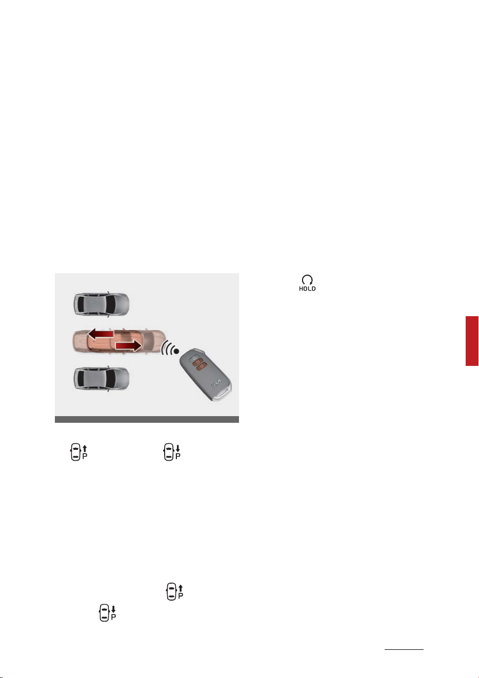
199
6
6
Driving your vehicle Remote Smart Parking Assist (RSPA)
䳜 Drive below 5 km/h (3 mph) with
the engine on to use Remote
Operation function.
䳜 If the function is turned on again
after parallel parking is completed
by Remote Smart Parking Assist,
Remote Operation function can be
used.
䳜 Check that all smart keys are out
-
side the vehicle when using
Remote Operation function.
2. Remotely moving forward and
backward
1. Press and hold one of the Forward
( ) or Backward ( ) button on
the smart key. Remote Smart
Parking Assist will automatically
control the steering wheel, vehicle
speed and gearshift. The vehicle
will move in the direction of the
button pressed.
2. While Remote Operation function
is operating, if the you do not hold
down the Forward ( ) or Back
-
ward ( ) button, the vehicle will
stop and function control will
pause. The function will start
operating again when the button
is pressed and held again.
3. When the vehicle reaches the tar
-
get location, the function will turn
off.
4. When the driver gets on the vehi
-
cle with the smart key, a message
will appear informing the driver
Remote Operation function is
complete on the infotainment
system screen.
In addition, when the Remote
Start ( ) button is pressed on
the smart key, a message will
appear informing the driver
Remote Operation function is
complete and the engine will turn
off.
䳜 Remote Operation function will
operate only when the smart key
is within 4 m (13 ft.) from the
vehicle. If there is no vehicle
movement even when the For
-
ward or Backward button is
pressed on the smart key, check
the distance to the vehicle and
press the button again.
䳜 The detecting range of the smart
key may vary depending on the
surroundings that are affected by
radio waves such as transmission
tower, broadcast station, etc.
䳜 When remotely moving forward
using method (1), it is recognized
as an exit situation, and the vehi
-
OMQ4051180

Driving your vehicle
2006
Remote Smart Parking Assist (RSPA)
cle moves 4 m (13 ft.) to check for
pedestrians, animals or objects
around the vehicle. After confir
-
mation, the steering wheel is con
-
trolled according to the condition
ahead.
䳜 When remotely moving forward
using method (2), it is recognized
as a parking situation, and will
immediately control the steering
wheel according to the condition
ahead to assist with entering the
parking space and aligning the
vehicle. However, performance
may reduce depending on the
pedestrians, animals, shape of
objects, location, etc. around the
vehicle.
䳜 For moving remotely backward,
both method (1) and (2) aligns the
steering wheel first, and then will
only move the vehicle straight.
䳜 When remotely moving forward
or backward is completed, the
vehicle will automatically shift to
P (Park) and engage EPB (Elec
-
tronic Parking Brake).
CAUTION
䳜 When using Remote Operation
function, make sure that all pas
-
sengers have gotten out of the
vehicle.
䳜 Before leaving the vehicle, close
windows and sunroofs, and make
sure the engine is off before lock
-
ing the doors.
䳜 If the vehicle䳓s battery is dis
-
charged or Remote Smart Parking
Assist malfunctions when parked
in a narrow parking space,
Remote Operation function will
not operate. Always park your
vehicle in a space wide enough for
you to get in or out of your vehi
-
cle.
䳜 Please note that depending on
the parking space, you may not
be able to exit from the space you
have entered by using Remote
Operation function.
䳜 After parking, the surrounding
may change due to the move
-
ment of surrounding vehicles. If
this occurs, Remote Operation
function may not operate.
How to turn off Remote Operation
function while operating
䳜 Press the Remote Start ( ) but
-
ton on the smart key.
䳜 Press the Parking/View ( ) but
-
ton.
䳜 Press the Parking Safety ( )
button or select 'Cancel' on the
infotainment system screen.
䳜 Press the Remote Start ( ) but
-
ton on the smart key. Remote
Operation function will turn off.
At this time, the engine will turn
off.
䳜 Get on the vehicle with the smart
key. Remote Operation function

201
6
6
Driving your vehicle Remote Smart Parking Assist (RSPA)
will turn off. At this time, the
engine will remain on.
The function will pause in the fol
-
lowing conditions when:
䳜 There is a pedestrian, animal or
object in the direction the vehicle
is moving
䳜 The door or tailgate is open
䳜 The Forward ( ) or Backward
( ) button is not continuously
pressed
䳜 Simultaneously pressing multiple
buttons on a smart key
䳜 The smart key is not operated
within 4 m (13 ft.) from the vehi
-
cle
䳜 Button of another smart key is
pressed in addition to the operat
-
ing smart key
䳜 Blind-Spot Collision-Avoidance
Assist or Rear-Cross Traffic Colli
-
sion Assist operates while the
vehicle is being controlled in the
reverse direction
䳜 The vehicle moves 7 m (22 ft.)
while the smart key is pressed
with Remote Operation function
(maximum travel distance per
button press)
When Remote Moving Forward/
Backward function is paused, the
vehicle will stop. If the condition that
made the function to pause disap
-
pears, the function may operate
again.
The function will cancel in the fol
-
lowing conditions when:
䳜 The steering wheel is steered
䳜 The gear is shifted while the vehi
-
cle is moving
䳜 Operating EPB while the vehicle is
moving
䳜 The engine hood is open
䳜 Vehicle speed is above 5 km/h (3
mph)
䳜 Rapid acceleration occurs
䳜 Vehicle skid occurs
䳜 The wheel is stuck by an obstacle
and cannot move
䳜 There are pedestrians, animals or
objects at the front and rear of
the vehicle at the same time
䳜 Approximately 3 minutes and 50
seconds have past after Remote
Moving Forward/Backward func
-
tion has started to operate
䳜 The slope of the road exceeds the
operational range
䳜 The steering wheel, gearshift,
braking, and drive controls are not
working normally
䳜 The function is paused for more
than 1 minute
䳜 The total travel distance of the
vehicle has exceeded 14 m (45 ft.)
after Remote Operation function
operation
䳜 There is a problem with the smart
key or the smart key battery is
low
䳜 ABS, TCS or ESC operates due to
slippery road conditions

Driving your vehicle
2026
Remote Smart Parking Assist (RSPA)
䳜 The brake pedal or accelerator
pedal is depressed when all the
doors are closed
䳜 The smart key is outside the vehi
-
cle when the brake pedal is
depressed while the driver's door
is open.
䳜 The alarm of the Theft Alarm
System sounds
When Remote Operation function is
canceled, the vehicle will automati
-
cally stop, shift the gear to P (Park)
and engage EPB (Electronic Parking
Brake).
CAUTION
Check whether the doors are locked
when Remote Operation function is
canceled.
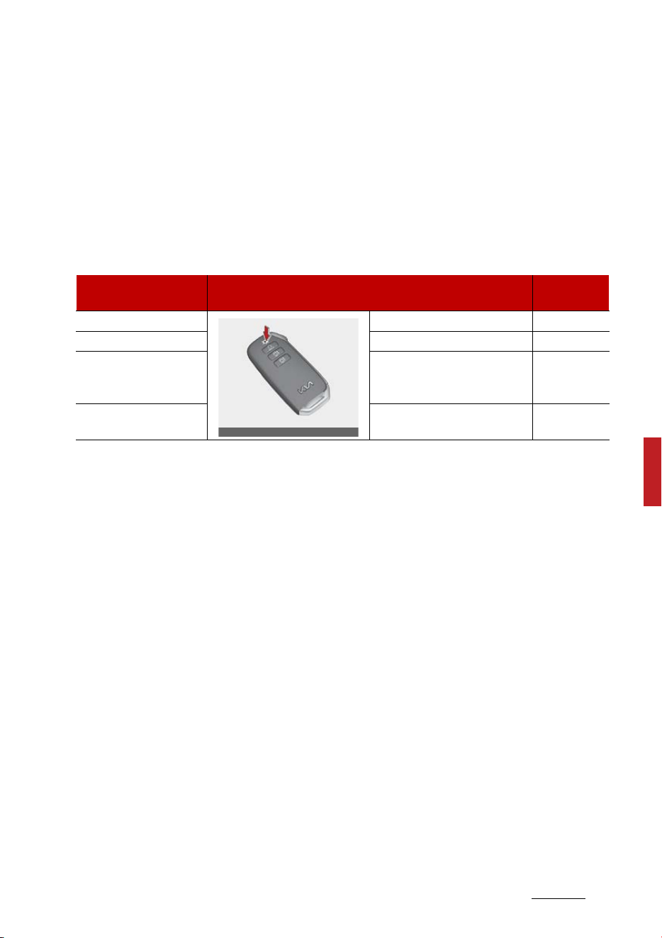
203
6
6
Driving your vehicle Remote Smart Parking Assist (RSPA)
Remote Operation status
Smart key LED/Hazard warning light
The operation status of Remote Smart Parking Assist is indicated by the smart key LED and the haz
-
ard warning light.
* Operation status by the hazard warning light may not be applicable based on the regulation of your
country.
* If the smart key is not within the operating range from the vehicle (approximately 4 m (13 ft.)), the
smart key LED will not illuminate or blink. Use the smart key within the operating range.
Operation Status Smart Key LED
Hazard
warning light
In operation Green LED Continuously blinks -
Paused Red LED Continuously blinks Blinks
Operation off
Red LED illuminates for 4 sec
-
onds and then turns off
Blinks 3
times and
turns off
Operation complete
Green LED illuminates for 4
seconds and then turns off
Blinks 1 time
and turns off
OMQ4041583
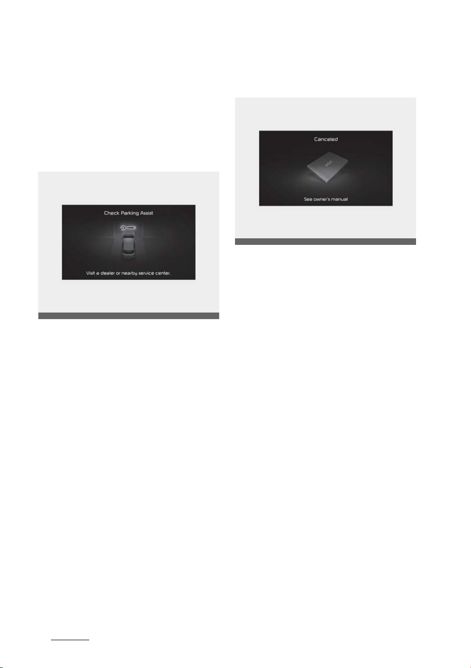
Driving your vehicle
2046
Remote Smart Parking Assist (RSPA)
Remote Smart Parking Assist Mal
-
function and Limitations
Remote Smart Parking Assist mal
-
function
Remote Smart Parking Assist check
When Remote Smart Parking Assist
is not working properly, the 'Check
Parking Assist' warning message will
appear on the infotainment system
screen. If the message appears,
stop using the function, and we rec
-
ommend that the function be
inspected by an authorized Kia
dealer/service partner.
Remote Smart Parking Assist can
-
celed
When Remote Smart Parking Assist
is operating, the function can be
canceled, and the 'Parking Assist
Canceled' warning message may
appear regardless of the parking
order. Other messages may appear
depending on the situations. Follow
the instructions provided on the
infotainment system screen while
parking your vehicle with Remote
Smart Parking Assist. Always look
around and pay attention when
using the function.
OMQ4050313L
OMQ4051315L

205
6
6
Driving your vehicle Remote Smart Parking Assist (RSPA)
Remote Smart Parking Assist
standby
When 'Parking Assist Conditions Not
Met' message appears, when Park
-
ing/View ( ) button has been
pressed and held, Remote Smart
Parking Assist is in standby. After a
while, press and hold the Parking/
View ( ) button again to see if the
function works.
The message appears even when
the smart key's battery is low.
Check the smart key battery level.
Limitations of Remote Smart Park
-
ing Assist
In the following circumstances,
function performance to park or exit
the vehicle may be limited, there
may be a risk of collision, or Remote
Smart Parking Assist may turn off.
Park or exit the vehicle manually if
necessary.
䳜 The parking space is curved or
diagonal
䳜 There is an obstacle such as a
trash can, bicycle, motorcycle,
shopping cart, narrow pillar etc.
near the parking space
䳜 There is a circular pillar or narrow
pillar, or a pillar surrounded by
objects such as fire extinguisher,
etc. near the parking space
䳜 There is heavy snow, rain or wind
䳜 The vehicle is installed with a
snow chain, spare tire or different
size wheel
䳜 Tire pressure is lower or higher
than the standard tire pressure
䳜 The road is bumpy
䳜 The road is slippery
䳜 The parking space is near a vehi
-
cle with higher ground clearance
or big, such as a truck, etc.
䳜 Your vehicle is loaded with cargo
longer or wider than your vehicle
or a trailer is connected to your
vehicle
䳜 The sensor is mounted or posi
-
tioned incorrectly by an impact to
the bumper
䳜 The parking space is Inclined
䳜 There is a problem with the wheel
alignment
䳜 Your vehicle is leaned severely to
one side
䳜 Front or rear ultrasonic sensors
are not working properly or does
not work (Refer to "Forward/
Reverse Parking Distance Warning
(PDW) (if equipped)" on page 4-
124.)
OMQ4051315L
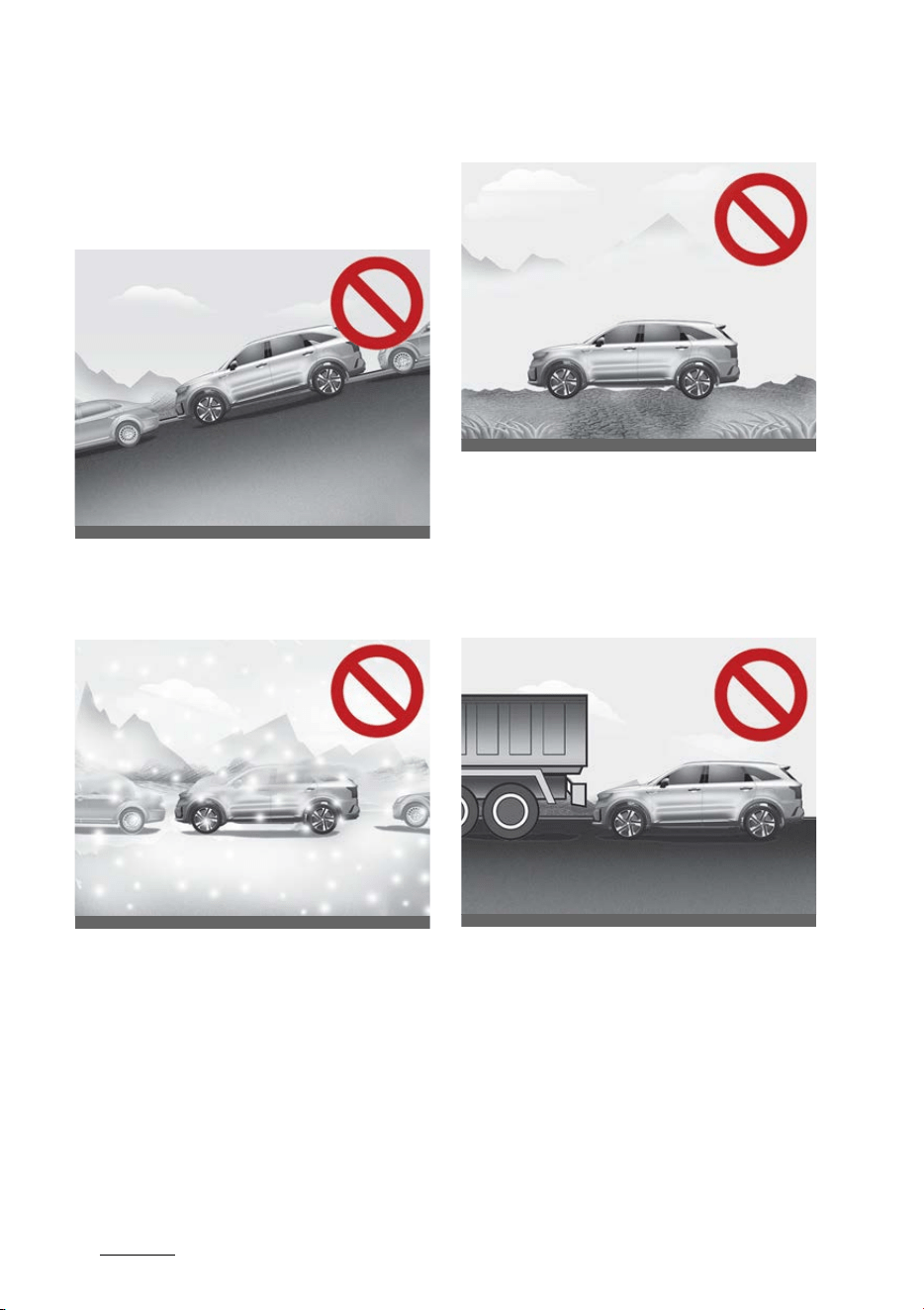
Driving your vehicle
2066
Remote Smart Parking Assist (RSPA)
Remote Smart Parking Assist may
not operate normally under the fol
-
lowing circumstances:
䳜 Parking on inclines
Park manually when parking on
inclines.
䳜 Parking in snow
Snow may interfere with sensor
operation, or Remote Smart Park
-
ing Assist may cancel if the road
is slippery while parking.
䳜 Parking on uneven road
Remote Smart Parking Assist
may cancel when the vehicle slips,
or the vehicle cannot move due to
road conditions such as pebbles or
fragmented stones.
䳜 Parking behind a truck
Do not use Remote Smart Parking
Assist around vehicles with higher
ground clearance, such as a bus,
truck, etc. It may lead to an acci
-
dent.
OMQ4H040022L
OMQ4H040023L
OMQ4H050014
OMQ4H050013
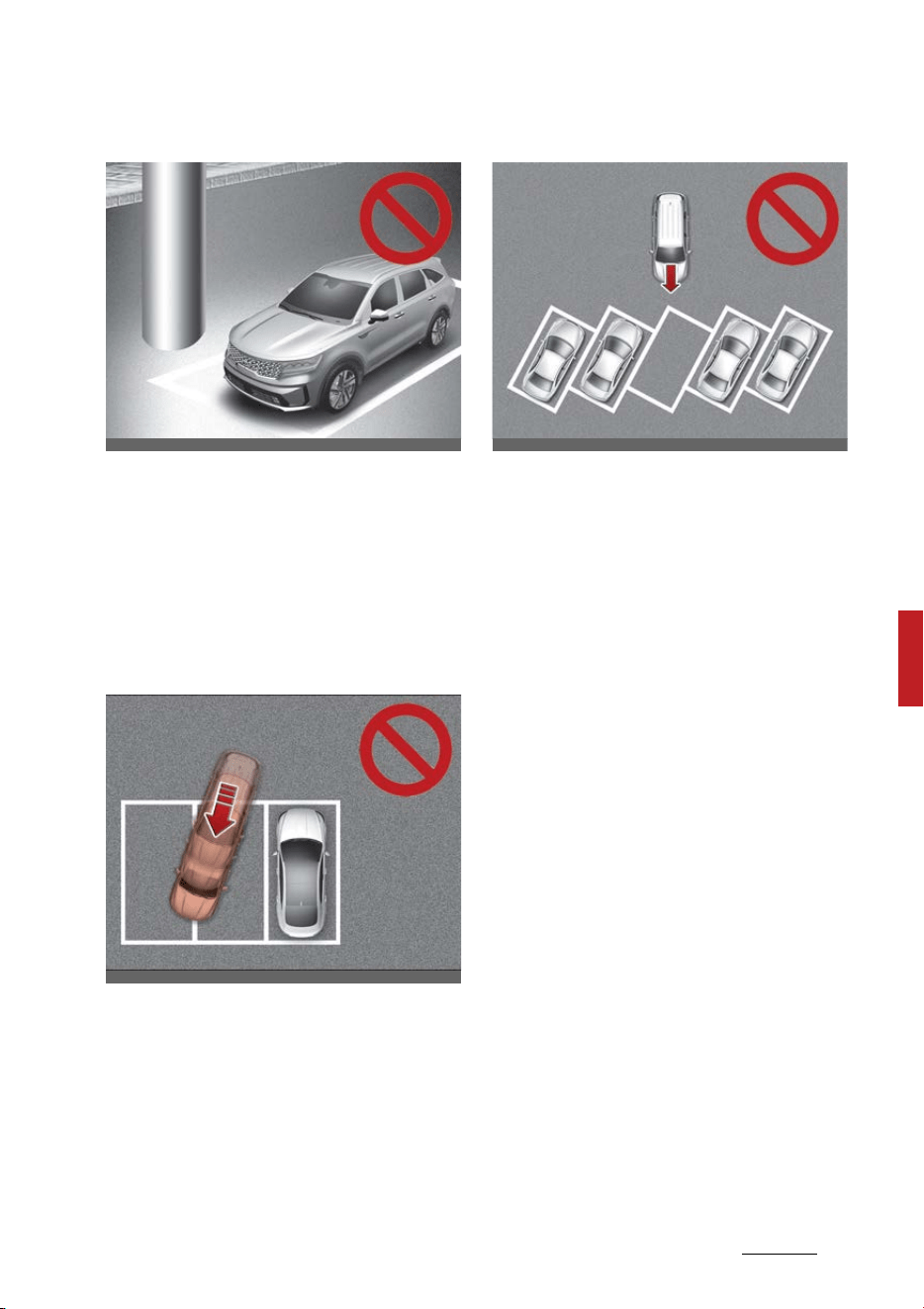
207
6
6
Driving your vehicle Remote Smart Parking Assist (RSPA)
䳜 Parking near a pillar
Remote Smart Parking Assist
performance may reduce when
there is a pillar or pillar sur
-
rounded by objects such as a fire
extinguisher near the parking
space.
䳜 Parking in a parking space with a
vehicle on one side only
If Remote Smart Parking Assist is
used, when parking in a parking
space with a vehicle only on one
side, your vehicle may cross the
parking line to avoid the parked
vehicle.
䳜 Parking diagonal
Remote Smart Parking Assist
does not provide diagonal parking.
Even if your vehicle was able to
enter the parking space, do not
use the function because the
function cannot operate normally.
OMQ4H051015
OMQ4050195
OMQ4050191

Driving your vehicle
2086
Economical operation
Economical operation
Your vehicle's fuel economy depends
mainly on your style of driving,
where you drive and when you drive.
Each of these factors affects how
many kilometers (miles) you can get
from a liter (gallon) of fuel. To oper
-
ate your vehicle as economically as
possible, use the following driving
suggestions to help save money in
both fuel and repairs:
䳜 Drive smoothly. Accelerate at a
moderate rate. Don't make "jack
-
rabbit" starts or full-throttle
shifts and maintain a steady
cruising speed. Don't race
between stoplights. Try to adjust
your speed to the traffic so you
don't have to change speeds
unnecessarily. Avoid heavy traffic
whenever possible.
Always maintain a safe distance
from other vehicles so you can
avoid unnecessary braking. This
also reduces brake wear.
䳜 Drive at a moderate speed. The
faster you drive, the more fuel
your vehicle uses. Driving at a
moderate speed, especially on the
highway, is one of the most
effective ways to reduce fuel con
-
sumption.
䳜 Take care of your tires. Keep
them inflated to the recom
-
mended pressure. Incorrect infla
-
tion, either too much or too little,
results in unnecessary tire wear.
Check the tire pressures at least
once a month.
䳜 Be sure that the wheels are
aligned correctly. Improper align
-
ment can result from hitting
curbs or driving too fast over
irregular surfaces. Poor alignment
causes faster tire wear and may
also result in other problems as
well as greater fuel consumption.
䳜 Keep your vehicle in good condi
-
tion. For better fuel economy and
reduced maintenance costs,
maintain your vehicle in accor
-
dance with the maintenance
schedule in "Scheduled mainte
-
nance service" on page 8-10. If
you drive your vehicle in severe
conditions, more frequent main
-
tenance is required (Refer to
"Maintenance under severe usage
conditions" on page 8-15).
䳜 Travel lightly. Don't carry unnec
-
essary weight in your vehicle.
Weight reduces fuel economy.
䳜 Don't let the engine idle longer
than necessary. If you are waiting
(and not in traffic), turn off your
engine and restart only when
you're ready to go.
䳜 Don't "lug" or "over-rev" the
engine. Lugging is driving too
slowly in too high a gear resulting
in the engine bucking. If this hap
-
pens, shift to a lower gear. Over-
revving is racing the engine
beyond its safe limit. This can be
209
6
6
Driving your vehicle Declaration of conformity
avoided by shifting at the recom
-
mended speeds.
䳜 Open windows at high speeds can
reduce fuel economy.
䳜 Fuel economy is less in cross
-
winds and headwinds. To help off
-
set some of this loss, slow down
when driving in these conditions.
Keeping a vehicle in good operating
condition is important both for
economy and safety.
Therefore, have the system checked
by an authorized Kia dealer.
WARNING
Engine off during motion
Never turn the engine off to coast
down hills or anytime the vehicle is
in motion. The power steering and
power brakes will not function prop
-
erly without the engine running. In
addition, turning off the vehicle
while driving could engage the
steering wheel lock resulting in loss
of vehicle steering. Keep the engine
on and downshift to an appropriate
gear for engine braking effect.
Declaration of conformity (if
equipped)
The radio frequency components
(Front Radar) complies:
For Europe and countries subject to
CE certification
For Taiwan
CCAI19LP0490T6
OMQ4PH051413L
OMQ4PH051411L
Driving your vehicle
2106
Declaration of conformity
For Australia
For Serbia
For Oman
For Moldova
OCK060094TW
OCK060062L
OMQ4PH051415L
OKA4050558L
OCK060065L
211
6
6
Driving your vehicle Declaration of conformity
For Ukraine
For UAE
For Brazil
For Singapore
For Russia
For Malaysia
ODL3059228L
OCK060066L
OMQ4PH051418L
OMQ4PH051419L
OMQ4PH051420L
ODL3059224L
OMQ4PH051421L
Driving your vehicle
2126
Declaration of conformity
For Jordan
For Mexico
For Israel
The radio frequency components
(Rear Corner Radar) complies:
For Ukraine
For Ghana
For Republic of South Africa
OMQ4PH051422L
OKA4050562L
OMQ4PH051423L
OMQ4PH051399L
OMQ4061053L
OMQ4PH051400L
OMQ4PH051401L
213
6
6
Driving your vehicle Declaration of conformity
For Serbia
For Paraguay
For Malaysia
For Singapore
For Europe and countries subject to
CE certification
For Thailand
OMQ4PH051403L
OMQ4PH051404L
OMQ4PH051405L
OMQ4PH051406L
OMQ4PH051407L
OMQ4PH051408L

Driving your vehicle
2146
Declaration of conformity
For Israel
For Brazil
For Taiwan
For UAE
For Jordan
OMQ4PH051409L
OMQ4PH051419L
OMQ4061055L
OMQ4061056L
OMQ4061058L
OMQ4061057L
215
6
6
Driving your vehicle Special driving conditions
For Mexico
Radio frequency radiation exposure
information:
This equipment complies with FCC
radiation exposure limits set forth
for an uncontrolled environment.
This equipment should be installed
and operated with minimum dis
-
tance of 8 in (20 cm) between the
radiator (antenna) and your body.
This transmitter must not be colo
-
cated or operating in conjunction
with any other antenna or trans
-
mitter.
Special driving conditions
If driving conditions deteriorate due
to poor weather or road conditions,
you should pay even more attention
than usual to your driving.
Hazardous driving conditions
When hazardous driving conditions
are encountered such as water,
snow, ice, mud, sand, or similar haz
-
ards, follow these suggestions:
䳜 Drive cautiously and allow extra
distance for braking.
䳜 Avoid sudden braking or steering.
䳜 Do not pump the brake pedal on a
vehicle equipped with ABS.
䳜 If stalled in snow, mud, or sand,
use the second gear. Accelerate
slowly to avoid spinning the drive
wheels.
䳜 Use sand, rock salt, or other non
-
slip material under the drive
wheels to provide traction when
stalled in ice, snow, or mud.
Reducing the risk of a rollover
This multi-purpose passenger vehi
-
cle is defined as a Sports Utility
Vehicle (SUV). Utility vehicles have a
significantly higher rollover rate
than other types of vehicles. SUVs
have higher ground clearance and a
narrower track to make them capa
-
ble of performing in a wide variety
of offroad applications.
OMQ4A061072

Driving your vehicle
2166
Special driving conditions
Specific design characteristics give
them a higher center of gravity than
ordinary vehicles. An advantage of
the higher ground clearance is a
better view of the road, which
allows you to anticipate problems.
They are not designed for cornering
at the same speeds as conventional
passenger vehicles, any more than
low-slung sports vehicles are
designed to perform satisfactorily in
off-road conditions. Due to this risk,
driver and passengers are strongly
recommended to buckle their seat
belts.
In a rollover crash, an unbelted per
-
son is significantly more likely to die
than a person wearing a seat belt.
There are steps that a driver can
make to reduce the risk of a rollover.
If at all possible, avoid sharp turns
or abrupt maneuvers, do not load
your roof rack with heavy cargo,
and never modify your vehicle in any
way.
WARNING
Rollover
As with other Sports Utility Vehicle
(SUV), failure to operate this vehicle
correctly may result in loss of con
-
trol, an accident or vehicle rollover.
䳜 Utility vehicles have a significantly
higher rollover rate than other
types of vehicles.
䳜 Specific design characteristics
(higher ground clearance, nar
-
rower track, etc.) give this vehicle
a higher center of gravity than
ordinary vehicles.
䳜 A SUV is not designed for corner
-
ing at the same speeds as con
-
ventional vehicles.
䳜 Avoid sharp turns or abrupt
maneuvers.
䳜 In a rollover crash, an unbelted
person is significantly more likely
to die than a person wearing a
seat belt. Make sure everyone in
the vehicle is properly buckled up.
WARNING
Your vehicle is equipped with tires
designed to provide safe ride and
handling capability. Do not use tires
and wheels that are different in size
and type from the originally
installed ones. It can affect the
safety and performance of your
vehicle, which could lead to steering
failure or rollover and serious injury.
When replacing the tires, be sure to
equip all four tires with the tire and
wheel of the same size, type, tread,
brand and load-carrying capacity.
Rocking the vehicle
If it is necessary to rock the vehicle
to free it from snow, sand, or mud,
first turn the steering wheel right
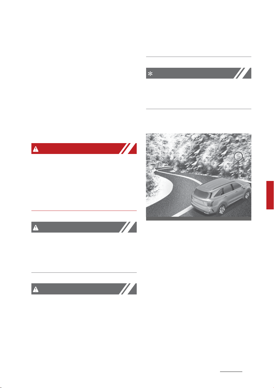
217
6
6
Driving your vehicle Special driving conditions
and left to clear the area around
your front wheels. Then, shift back
and forth between R (Reverse) and
any forward gear.
Do not race the engine, and spin the
wheels as little as possible. If you
are still stuck after a few tries, have
the vehicle pulled out by a tow vehi
-
cle to avoid engine overheating and
possible damage to the transmis
-
sion.
WARNING
Sudden vehicle movement
Do not attempt to rock the vehicle if
people or objects are nearby. The
vehicle may suddenly move forward
or backwards as it becomes
unstuck.
CAUTION
Vehicle rocking
Prolonged rocking may cause vehicle
overheating, transmission damage
or failure, and tire damage.
CAUTION
Spinning tires
Do not spin the wheels, especially at
speeds more than 35 mph (56 km/
h). Spinning the wheels at high
speeds when the vehicle is station
-
ary could overheat and damage
tires, and the rotating wheels may
fly away and injure bystanders.
NOTICE
The Electronic Stability Control
(ESC) should be turned OFF prior to
rocking the vehicle.
Smooth cornering
Avoid braking or gear changing in
corners, especially when roads are
wet. Ideally, corners should always
be taken under gentle acceleration.
If you follow these suggestions, tire
wear will be held to a minimum.
OMQ4AH051198
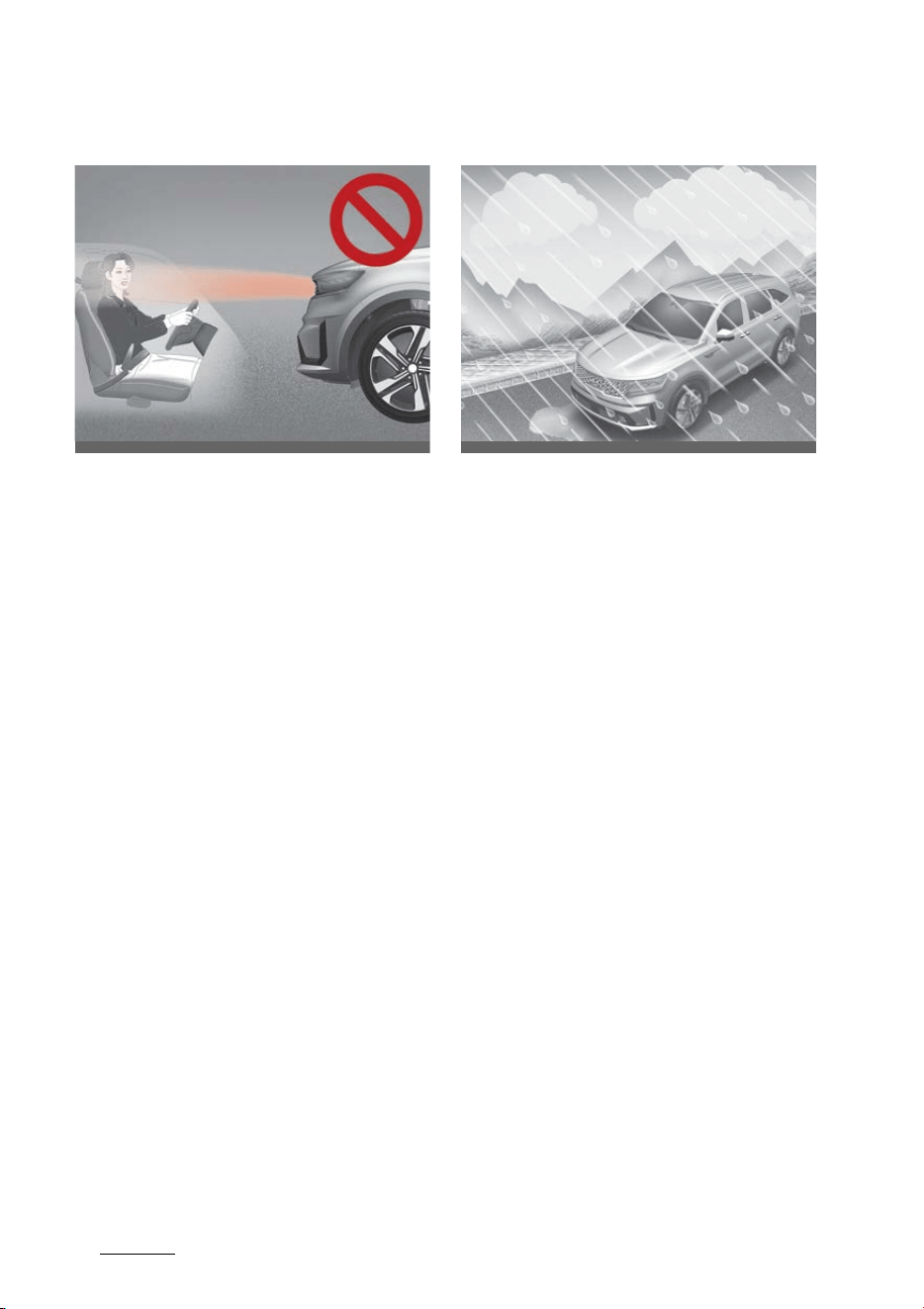
Driving your vehicle
2186
Special driving conditions
Driving at night
Because night driving presents more
hazards than driving in the daylight,
here are some important tips to
remember:
䳜 Slow down and keep more dis
-
tance between you and other
vehicles, as it may be more diffi
-
cult to see at night, especially in
areas where there may not be
any street lights.
䳜 Adjust your mirrors to reduce the
glare from other driver's head
-
lamps.
䳜 Keep your headlamps clean and
properly aimed. (On vehicles not
equipped with the automatic
headlamp aiming feature.) Dirty
or improperly aimed headlamps
will make it much more difficult to
see at night.
䳜 Avoid staring directly at the head
-
lamps of oncoming vehicles. You
could be temporarily blinded, and
it will take several seconds for
your eyes to readjust to the dark
-
ness.
Driving in the rain
Rain and wet roads can make driving
dangerous, especially if you're not
prepared for the slick pavement.
Here are a few things to consider
when driving in the rain:
䳜 A heavy rainfall will make it
harder to see and will increase the
distance needed to stop your
vehicle, so slow down.
䳜 Keep your windshield wiping
equipment in good shape. Replace
your windshield wiper blades
when they show signs of streak
-
ing or missing areas on the wind
-
shield.
䳜 If your tires are not in good condi
-
tion, making a quick stop on wet
pavement can cause a skid and
possibly lead to an accident. Be
sure your tires are in good shape.
䳜 Turn on your headlamps to make
it easier for others to see you.
䳜 Driving too fast through large
puddles can affect your brakes. If
you must go through puddles, try
to drive through them slowly.
OMQ4H050018
OMQ4H061016L
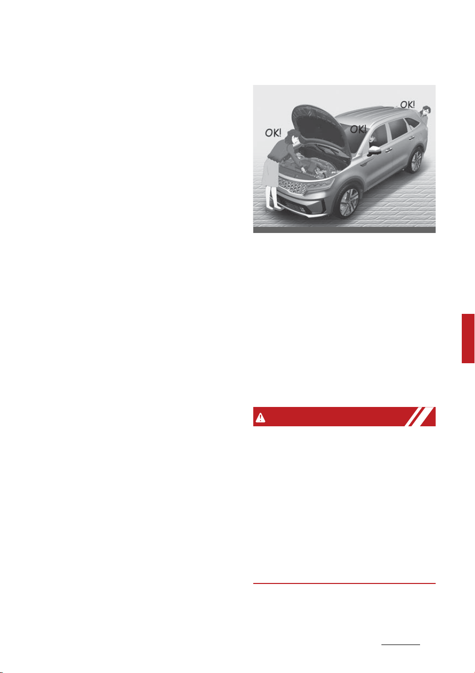
219
6
6
Driving your vehicle Special driving conditions
䳜 If you believe you may have got
-
ten your brakes wet, apply them
lightly while driving until normal
braking operation returns.
Hydroplaning
If the road is wet enough and you
are going fast enough, your vehicle
may have little or no contact with
the road surface and actually ride
on the water. The best advice is
SLOW DOWN when the road is wet.
The risk of hydroplaning increases
as the depth of tire tread decreases,
refer to"Tires and wheels" on page
8-38.
Driving in flooded areas
Avoid driving through flooded areas
unless you are sure the water is no
higher than the bottom of the wheel
hub. Drive through any water
slowly. Allow adequate stopping dis
-
tance because brake performance
may be affected.
After driving through water, dry the
brakes by gently applying them
several times while the vehicle is
moving slowly.
Highway driving
Tires
Adjust the tire inflation pressures to
specification. Low tire inflation pres
-
sures will result in overheating and
possible failure of the tires.
Avoid using worn or damaged tires
which may result in reduced traction
or tire failure.
Never exceed the maximum tire
inflation pressure shown on the
tires.
WARNING
Under/over inflated tires
Always check the tires for proper
inflation before driving. Underin
-
flated or overinflated tires can
cause poor handling, loss of vehicle
control, and sudden tire failure,
leading to accidents, injuries, and
even death. For proper tire pres
-
sures, refer to "Tires and wheels" on
page 8-38.
OMQ4PH051337

Driving your vehicle
2206
Winter driving
WARNING
Tire tread
Always check the tire tread before
driving your vehicle. Worn-out tires
can result in loss of vehicle control.
Worn-out tires should be replaced
as soon as possible. For further
information and tread limits, refer
to "Tires and wheels" on page 8-38.
Fuel, engine coolant and engine oil
High speed travel consumes more
fuel than urban motoring. Do not
forget to check both the engine
coolant and engine oil.
Drive belt
A loose or damaged drive belt may
result in overheating of the engine.
Winter driving
Severe weather conditions in the
winter result in greater wear and
other problems.
To minimize the problems of winter
driving, you should follow these
suggestions:
Snowy or icy conditions
To drive your vehicle in deep snow, it
may be necessary to use snow tires
or to install tire chains on your tires.
If snow tires are needed, it is neces
-
sary to select tires equivalent in size
and type of the original equipment
tires. Failure to do so may adversely
affect the safety and handling of
your vehicle. Furthermore, speeding,
rapid acceleration, sudden brake
applications, and sharp turns are
potentially very hazardous prac
-
tices.
During deceleration, use vehicle
braking to the fullest extent. Sud
-
den brake applications on snowy or
icy roads may cause skids to occur.
You need to keep sufficient distance
between the vehicle in operation in
front of your vehicle. Also, apply the
brake gently. It should be noted that
installing tire chains on the tire will
provide a greater driving force, but
will not prevent side skids.
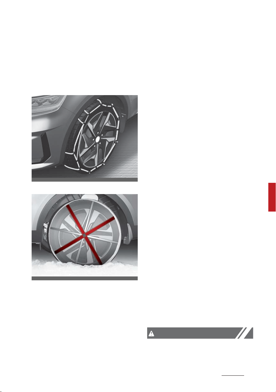
221
6
6
Driving your vehicle Winter driving
Tire chains are not legal in all states.
Check state laws before fitting tire
chains.
Tire chains
wire-type
fabric-type
Since the sidewalls of radial tires are
thinner, they can be damaged by
mounting some types of snow
chains on them. Therefore, the use
of snow tires is recommended
instead of snow chains. Do not
mount tire chains on vehicles
equipped with aluminum wheels;
snow chains may cause damage to
the wheels. If snow chains must be
used, use fabric-type chains for 19
inch tires or wire-type chains for 17
inch tires with a thickness of less
than 0.47 in (12 mm).
Damage to your vehicle caused by
improper snow chain use is not cov
-
ered by your vehicle manufacturers
warranty.
When using tire chains, attach them
to the drive wheels as follows.
䳜 Front wheel drive vehicle moves
the front wheel as a power
source. Thus, snow chains must
be mounted to front tires.
䳜 After mounting snow chains, drive
slowly. If you hear noise caused
by chains contacting the body,
slow down until the noise stops
and remove the chain as soon as
you begin driving on cleared roads
to prevent damage.
䳜 Wrong size chains or improperly
installed chains can damage your
vehicle's brake lines, suspension,
body and wheels. Therefore,
when installing snow chain, follow
the manufacturer's instructions
and mount them as tightly possi
-
ble. Drive slowly (less than 20
mph (30 km/h)) with chains
installed.
CAUTION
䳜 Make sure the snow chains are
the correct size and type for your
OMQ4H050037
OMQ4H050036

Driving your vehicle
2226
Winter driving
tires. Incorrect snow chains can
cause damage to the vehicle body
and suspension and may not be
covered by your vehicle manufac
-
turer warranty. Also, the snow
chain connecting hooks may be
damaged from contacting vehicle
components causing the snow
chains to come loose from the
tire. Make sure the snow chains
are SAE class "S" certified.
䳜 Always check chain installation for
proper mounting after driving
approximately 0.3 to 0.6 miles
(0.5 to 1 km) to ensure safe
mounting. Retighten or remount
the chains if they are loose.
䳜 Fabric-type chains must be used
on the vehicle with 19 inch (235/
55R19) tires.
Snow tires
If you mount snow tires on your
vehicle, make sure they are radial
tires of the same size and load
range as the original tires. Mount
snow tires on all four wheels to bal
-
ance your vehicle's handling in all
weather conditions. Keep in mind
that the traction provided by snow
tires on dry roads may not be as
high as your vehicle's original equip
-
ment tires. You should drive cau
-
tiously even when the roads are
clear. Check with the tire dealer for
maximum speed recommendations.
Do not install studded tires without
first checking local, state and
municipal regulations for possible
restrictions against their use.
WARNING
Snow tire size
Snow tires should be equivalent in
size and type to the vehicle's stan
-
dard tires. Otherwise, the safety
and handling of your vehicle may be
adversely affected.
Use high quality ethylene glycol
coolant
Your vehicle is delivered with high
quality ethylene glycol coolant in the
cooling system. It is the only type of
coolant that should be used because
it helps prevent corrosion in the
cooling system, lubricates the water
pump and prevents freezing. Be
sure to replace or replenish your
coolant in accordance with the
maintenance schedule in section 8.
Before winter, have your coolant
tested to assure that its freezing
point is sufficient for the tempera
-
tures anticipated during the winter.
Check battery and cables
Winter puts additional burdens on
the battery system. Visually inspect
the battery and cables as described
in section 8. Have the level of charge

223
6
6
Driving your vehicle Winter driving
in your battery checked by an
authorized Kia dealer.
Change to "winter weight" oil if
necessary
In some climates it is recommended
that a lower viscosity "winter
weight" oil be used during cold
weather. See "Recommended lubri
-
cants and capacities" on page 9-8. If
you aren't sure what weight oil you
should use, consult an authorized
Kia dealer.
Check spark plugs and ignition sys
-
tem
Inspect your spark plugs as
described in "Scheduled mainte
-
nance service" on page 8-10 and
replace them if necessary. Also
check all ignition wiring and compo
-
nents to be sure they are not
cracked, worn or damaged in any
way.
To keep locks from freezing
To keep the locks from freezing,
squirt an approved de-icer fluid or
glycerine into the key opening. If a
lock is covered with ice, squirt it with
an approved de-icing fluid to remove
the ice. If the lock is frozen inter
-
nally, you may be able to thaw it out
by using a heated key. Handle the
heated key with care to avoid injury.
Use approved window washer anti-
freeze in system
To keep the water in the window
washer system from freezing, add
an approved window washer anti-
freeze solution in accordance with
instructions on the container. Win
-
dow washer anti-freeze is available
from an authorized Kia dealer and
most auto parts outlets. Do not use
engine coolant or other types of
anti-freeze as these may damage
the paint finish.
Don't let your parking brake freeze
Under some conditions your parking
brake can freeze in the engaged
position. This is most likely to hap
-
pen when there is an accumulation
of snow or ice around or near the
rear brakes or if the brakes are wet.
If there is a risk the parking brake
may freeze, temporarily apply it
with the gear in P (Park). Also, block
the rear wheels in advance, so the
vehicle may not roll. Then release
the parking brake.
Don't let ice and snow accumulate
underneath
Under some conditions, snow and
ice can build up under the fenders
and interfere with the steering.
When driving in severe winter condi
-
tions where this may happen, you
should periodically check under
-

Driving your vehicle
2246
Trailer towing
neath the vehicle to be sure the
movement of the front wheels and
the steering components is not
obstructed.
Carry emergency equipment
Depending on the severity of the
weather, you should carry appropri
-
ate emergency equipment. Some of
the items you may want to carry
include tire chains, tow straps or
chains, flashlight, emergency flares,
sand, shovel, jumper cables, window
scraper, gloves, ground cloth, cover
-
alls, blanket, etc.
Do not place objects or materials in
the engine compartment
Putting objects or materials in the
engine compartment may cause an
engine failure or combustion,
because they may block the engine
cooling. Such damage will not be
covered by the manufacturer's war
-
ranty.
Trailer towing (if equipped)
If you are considering towing with
your vehicle, you should first check
with your country's Department of
Motor Vehicles to determine their
legal requirements.
Since laws vary the requirements
for towing trailers, cars, or other
types of vehicles or apparatus may
differ. Kia recommends to ask an
authorized Kia dealer.
WARNING
Towing a trailer
If you don't use the correct equip
-
ment and drive improperly, you can
lose control when you pull a trailer.
For example, if the trailer is too
heavy, the brakes may not work
well - or even at all. You and your
passengers could be seriously or
fatally injured. Pull a trailer only if
you have followed all the steps in
this section.
WARNING
Weight limits
Before towing, make sure the total
trailer weight, gross combination
weight, gross vehicle weight, gross
axle weight and trailer tongue load
are all within the limits.

225
6
6
Driving your vehicle Trailer towing
NOTICE
䳜 The technically permissible maxi
-
mum load on the rear axle(s) may
be exceeded by not more than 15
% and the technically permissible
maximum laden mass of the vehi
-
cle may be exceeded by not more
than 10 % or 220.4 lbs (100 kg),
whichever value is lower. In this
case, do not exceed 60 mph (100
km/h) for vehicle of category M1
or 50 mph (80 km/h) for vehicle of
category N1.
䳜 When towing a trailer, the addi
-
tional load imposed at the trailer
coupling device may cause the
rear tire maximum load ratings to
be exceeded, but not by more
than 15%. In such a case, do not
exceed 60 miles (100km/h), and
the rear tire pressure should be at
least 0.2 bar (20 kPa) above the
tire pressure(s) as recommended
for normal use (i.e. without a
trailer attached).
CAUTION
Pulling a trailer improperly can
damage your vehicle and result in
costly repairs not covered by your
warranty. To pull a trailer correctly,
follow the advice in this section.
Your vehicle can tow a trailer. To
identify what the vehicle trailering
capacity is for your vehicle, refer to
"Weight of the trailer" on page 6-
232 that appears later in this sec
-
tion.
Remember that trailering is differ
-
ent than just driving your vehicle by
itself. Trailering means changes in
handling, durability, and fuel econ
-
omy. Successful, safe trailering
requires correct equipment, and it
has to be used properly.
This section contains many
timetested, important trailering tips
and safety rules. Many of these are
important for your safety and that
of your passengers. Please read this
section carefully before you pull a
trailer.
Load-pulling components such as
the engine, transmission, wheel
assemblies, and tires are forced to
work harder against the load of the
added weight. The engine is
required to operate at relatively
higher speeds and under greater
loads. This additional burden gener
-
ates extra heat. The trailer also
considerably adds wind resistance,
increasing pulling requirements.
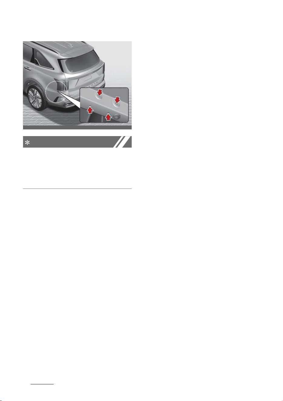
Driving your vehicle
2266
Trailer towing
NOTICE
Location of trailer mounting
The mounting hole for hitches are
located on both sides of the under
-
body behind the rear tires.
Hitches
It's important to have the correct
hitch equipment. Crosswinds, large
trucks going by, and rough roads are
a few reasons why you'll need the
right hitch. Here are some rules to
follow:
䳜 Do you have to make any holes in
the body of your vehicle when you
install a trailer hitch? If you do,
then be sure to seal the holes
later when you remove the hitch.
If you don't seal them, deadly car
-
bon monoxide (CO) from your
exhaust can get into your vehicle,
as well as dirt and water.
䳜 The bumpers on your vehicle are
not intended for hitches. Do not
attach rental hitches or other
bumper-type hitches. Use only a
frame-mounted hitch that does
not attach to the bumper.
䳜 Kia trailer hitch accessory is avail
-
able at an authorized Kia dealer.
Safety chains
You should always attach chains
between your vehicle and your
trailer. Cross the safety chains
under the tongue of the trailer so
that the tongue will not drop to the
road if it becomes separated from
the hitch.
Instructions about safety chains
may be provided by the hitch manu
-
facturer or by the trailer manufac
-
turer. Follow the manufacturer's
recommendation for attaching
safety chains. Always leave just
enough slack so you can turn with
your trailer. And, never allow safety
chains drag on the ground.
Trailer brakes
If your trailer is equipped with a
braking system, make sure it con
-
forms to your country's regulations
and that it is properly installed and
operating correctly.
If your trailer weighs more than the
maximum trailer weight without
trailer brakes loaded, then it needs
its own brakes and they must be
adequate. Be sure to read and fol
-
low the instructions for the trailer
OMQ4AH051279

227
6
6
Driving your vehicle Trailer towing
brakes so you'll be able to install,
adjust and maintain them properly.
䳜 Don't tap into your vehicle's brake
system.
WARNING
Trailer brakes
Do not use a trailer with its own
brakes unless you are absolutely
certain that you have properly set
up the brake system. This is not a
task for amateurs. Use an experi
-
enced, competent trailer shop for
this work.
Driving with a trailer
Towing a trailer requires a certain
amount of experience. Before set
-
ting out for the open road, you must
get to know your trailer. Acquaint
yourself with the feel of handling
and braking with the added weight
of the trailer. And always keep in
mind that the vehicle you are driving
is now a good deal longer and not
nearly so responsive as your vehicle
is by itself.
Before you start, check the trailer
hitch and platform, safety chains,
electrical connector(s), lights, tires
and mirror adjustment. If the trailer
has electric brakes, start your vehi
-
cle and trailer moving and then
apply the trailer brake controller by
hand to be sure the brakes are
working. This lets you check your
electrical connection at the same
time.
During your trip, check occasionally
to be sure that the load is secure,
and that the lights and trailer
brakes are still working.
Following distance
Stay at least twice as far behind the
vehicle ahead as you would when
driving your vehicle without a trailer.
This can help you avoid situations
that require heavy braking and sud
-
den turns.
Passing
You'll need more passing distance up
ahead when you're towing a trailer.
And, because of the increased vehi
-
cle length, you'll need to go much
farther beyond the passed vehicle
before you can return to your lane.
Backing up
Hold the bottom of the steering
wheel with one hand. Then, to move
the trailer to the left, just move
your hand to the left. To move the
trailer to the right, move your hand
to the right. Always back up slowly
and, if possible, have someone guide
you.

Driving your vehicle
2286
Trailer towing
Making turns
When you're turning with a trailer,
make wider turns than normal. Do
this so your trailer won't strike soft
shoulders, curbs, road signs, trees,
or other objects. Avoid jerky or sud
-
den maneuvers. Signal well in
advance.
Turn signals when towing a trailer
When you tow a trailer, your vehicle
has to have a different turn signal
flasher and extra wiring. The green
arrows on your instrument panel
will flash whenever you signal a turn
or lane change. Properly connected,
the trailer lights will also flash to
alert other drivers you're about to
turn, change lanes, or stop.
When towing a trailer, the green
arrows on your instrument panel
will flash for turns even if the bulbs
on the trailer are burned out. Thus,
you may think drivers behind you
are seeing your signals when, in
fact, they are not. It's important to
check occasionally to be sure the
trailer bulbs are still working. You
must also check the lights every
time you disconnect and then
reconnect the wires.
Do not connect a trailer lighting sys
-
tem directly to your vehicle's light
-
ing system. Use only an approved
trailer wiring harness.
Have yourself assisted by a profes
-
sional workshop in installing the
wiring harness.
Kia recommends to visit an autho
-
rized Kia dealer.
WARNING
Failure to use an approved trailer
wiring harness could result in dam
-
age to the vehicle electrical system
and/or personal injury.
Driving on grades
Reduce the speed and shift to a
lower gear before you start down a
long or steep downgrade. If you
don't shift down, you might have to
use your brakes so much that they
would get hot and no longer operate
efficiently.
On a long uphill grade, shift down
and reduce your speed to around 45
mph (70 km/h) to reduce the possi
-
bility of engine and transmission
overheating.
CAUTION
䳜 When towing a trailer on steep
grades (in excess of 6 %) pay
close attention to the engine
coolant temperature gauge to
ensure the engine does not over
-
heat. If the needle of the coolant
temperature gauge moves across
the dial towards "H (HOT) (or 260

229
6
6
Driving your vehicle Trailer towing
F/130 C)", pull over and stop as
soon as it is safe to do so, and
allow the engine to idle until it
cools down. You may proceed
once the engine has cooled suffi
-
ciently.
䳜 You must decide the driving speed
depending on trailer weight and
uphill grade to reduce the possi
-
bility of engine and transmission
overheating.
Parking on hills
Generally, if you have a trailer
attached to your vehicle, you should
not park your vehicle on a hill. Peo
-
ple can be seriously or fatally
injured, and both your vehicle and
the trailer can be damaged if unex
-
pectedly roll down hill.
WARNING
Parking on a hill
Parking your vehicle on a hill with a
trailer attached could cause serious
injury or death, should the trailer
break loose.
However, if you ever have to park
your trailer on a hill, here's how to
do it:
1. Pull the vehicle into the parking
space. Turn the steering wheel in
the direction of the curb (right if
headed down hill, left if headed up
hill).
2. Set the parking brake and shut off
the vehicle.
3. Place chocks under the trailer
wheels on the down hill side of
the wheels.
4. Start the vehicle, hold the brakes,
shift to neutral, release the park
-
ing brake and slowly release the
brakes until the trailer chocks
absorb the load.
5. Reapply the brakes, reapply the
parking brake.
6. Shut off the vehicle and release
the vehicle brakes but leave the
parking brake set.
WARNING
Parking brake
It can be dangerous to get out of
your vehicle if the parking brake is
not firmly set.
If you have left the engine running,
the vehicle can move suddenly. You
or others could be seriously or
fatally injured.
When you are ready to leave after
parking on a hill
1. Apply your brakes and hold the
brake pedal down while you:
䳜 Start your engine;
䳜 Shift into gear; and
䳜 Release the parking brake.
2. Slowly remove your foot from the
brake pedal.
3. Drive slowly until the trailer is
clear of the chocks.

Driving your vehicle
2306
Trailer towing
4. Stop and have someone pick up
and store the chocks.
Maintenance when trailer towing
Your vehicle will need service more
often when you regularly pull a
trailer. Important items to pay par
-
ticular attention to include engine
oil, axle lubricant and cooling system
fluid. Brake condition is another
important item to frequently check.
Each item is covered in this manual,
and the Index will help you find
them quickly. If you're trailering, it's
a good idea to review these sections
before you start your trip.
Don't forget to also maintain your
trailer and hitch. Follow the mainte
-
nance schedule that accompanied
your trailer and check it periodically.
Preferably, conduct the check at the
start of each day's driving. Most
importantly, all hitch nuts and bolts
should be tight.
CAUTION
䳜 Due to higher load during trailer
usage, overheating might occur in
hot days or during uphill driving. If
the coolant gauge indicates over
-
heating, switch off the A/C and
stop the vehicle in a safe area to
cool down the engine.
䳜 When towing, check the trans
-
mission fluid more frequently.
䳜 If your vehicle is not equipped
with an air conditioner, you should
install a condenser fan to improve
engine performance when towing
a trailer.
If you do decide to pull a trailer
Here are some important points if
you decide to pull a trailer:
䳜 Consider using a sway control.
You can ask a hitch dealer about
sway control.
䳜 Do not do any towing with your
vehicle during its first 1,200 miles
(2,000 km) in order to allow the
engine to properly break in. Fail
-
ure to heed this caution may
result in serious engine or trans
-
mission damage.
䳜 When towing a trailer, consult an
authorized Kia dealer on addi
-
tional requirements such as a
towing kit, etc.
䳜 Always drive your vehicle at a
moderate speed (less than 60
mph (100 km/h)).
䳜 On a long uphill grade, do not
exceed 45 mph (70 km/h) or the
posted towing speed limit, which
-
ever is lower.
䳜 The chart contains important
considerations that have to do
with weight:

231
6
6
Driving your vehicle Trailer towing
For hybrid vehicle
For plug-in hybrid vehicle
Item
Gasoline Engine
Smartstream G1.6 T-GDi HEV
Maximum
trailer weight
Without brake System 1,653 lbs. (750 kg)
With brake System 2,000 lbs. (907 kg)
Maximum permissible static vertical load on
the coupling device
220 lbs. (100 kg)
Recommended distance from rear wheel
center to coupling point
45.3 inch (1,150 mm)
Item
Gasoline Engine
Smartstream G1.6 T-GDi PHEV
Maximum
trailer weight*
Without brake System 1,653 lbs. (750 kg)
With brake
System
Smartstream
G 1.6 T-GDi
PHEV
2,000 lbs. (907 kg)
Maximum permissible static vertical load on
the coupling device
220 lbs. (100 kg)
Recommended distance from rear wheel
center to coupling point
45.3 inch (1,150 mm)
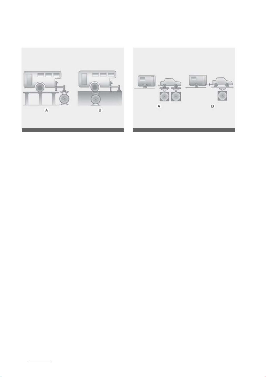
Driving your vehicle
2326
Trailer towing
Weight of the trailer
A: Tongue Load
B: Total Trailer Weight
What is the maximum safe weight
of a trailer? It should never weigh
more than the maximum trailer
weight with trailer brakes. But even
that can be too heavy.
It depends on how you plan to use
your trailer. For example, speed,
altitude, road grades, outside tem
-
perature and how often your vehicle
is used to pull a trailer are all
important. The ideal trailer weight
can also depend on any special
equipment that you have on your
vehicle.
Weight of the trailer tongue
A: Gross Axle Weight
B: Gross Vehicle Weight
The tongue load of any trailer is an
important weight to measure
because it affects the total gross
vehicle weight (GVW) of your vehi
-
cle. This weight includes the curb
weight of the vehicle, any cargo you
may carry in it, and the people who
will be riding in the vehicle. And if
you tow a trailer, you must add the
tongue load to the GVW because
your vehicle will also be carrying
that weight.
The trailer tongue should weigh a
maximum of 10% of the total
loaded trailer weight, within the lim
-
its of the maximum trailer tongue
load permissible.
After you've loaded your trailer,
weigh the trailer and then the
tongue, separately, to see if the
weights are proper. If they aren't,
you may be able to correct them
OUM076210L
OUM076211L
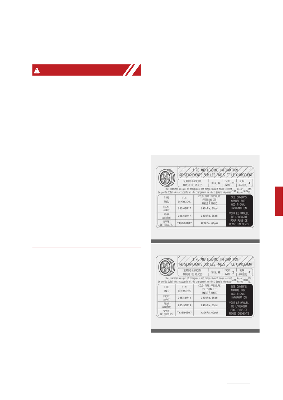
233
6
6
Driving your vehicle Vehicle load limit
simply by moving some items
around in the trailer.
WARNING
Trailer
䳜 Never load a trailer with more
weight in the rear than in the
front. The front should be loaded
with approximately 60% of the
total trailer load; the rear should
be loaded with approximately
40% of the total trailer load.
䳜 Never exceed the maximum
weight limits of the trailer or
trailer towing equipment.
Improper loading can result in
damage to your vehicle and/or
personal injury. Check weights
and loading at a commercial scale
or highway patrol office equipped
with scales.
䳜 An improperly loaded trailer can
cause loss of vehicle control.
Vehicle load limit
The vehicle load limit is displayed on
the tire and loading information
label on the driver's door.
Tire and loading information label
The label located on the driver's
door sill gives the original tire size,
cold tire pressures recommended
for your vehicle, the number of peo
-
ple that can be in your vehicle and
vehicle capacity weight.
Vehicle capacity weight:
1032 lbs. (468 kg)
OMQ4AH060052
OMQ4AH060053

Driving your vehicle
2346
Vehicle load limit
Vehicle capacity weight is the maxi
-
mum combined weight of occupants
and cargo. If your vehicle is equipped
with a trailer, the combined weight
includes the tongue load.
Seating capacity:
Total: 6 persons (Front seat: 2 per
-
sons, Rear seat: 4 persons)
Seating capacity is the maximum
number of occupants including a
driver, your vehicle may carry.
However, the seating capacity may
be reduced based upon the weight
of all of the occupants, and the
weight of the cargo being carried or
towed.
Do not overload the vehicle as there
is a limit to the total weight, or load
limit including occupants and cargo,
the vehicle can carry.
Towing capacity:
We do not recommend using this
vehicle for trailer towing.
Cargo capacity:
The cargo capacity of your vehicle
will increase or decrease depending
on the weight and the number of
occupants.
Steps for Determining Correct Load
Limit䳎
1. Locate the statement "The com
-
bined weight of occupants and
cargo should never exceed XXX
lbs. or XXX kg'' on your vehicle's
placard.
2. Determine the combined weight
of the driver and passengers that
will be riding in your vehicle.
3. Subtract the combined weight of
the driver and passengers from
XXX lbs or XXX kg.
4. The resulting figure equals the
available amount of cargo and
luggage load capacity. For exam
-
ple, if the "XXX" amount equals
1400 lbs. and there will be five
150 lbs. passengers in your vehi
-
cle, the amount of available cargo
and luggage load capacity is 650
lbs. (1400-750 (5x150) = 650 lbs.)
5. Determine the combined weight
of luggage and cargo being loaded
on the vehicle. That weight may
not safely exceed the available
cargo and luggage load capacity
calculated in Step 4.
6. If your vehicle will be towing a
trailer, load from your trailer will
be transferred to your vehicle.
Consult this manual to determine
how this reduces the available
cargo and luggage load capacity
of your vehicle.
WARNING
Loose cargo
Do not travel with unsecured blunt
objects in the passenger compart
-
ment of your vehicle (e.g., suit cases
or unsecured child seats). These
items may strike an occupant during
a sudden stop or crash.
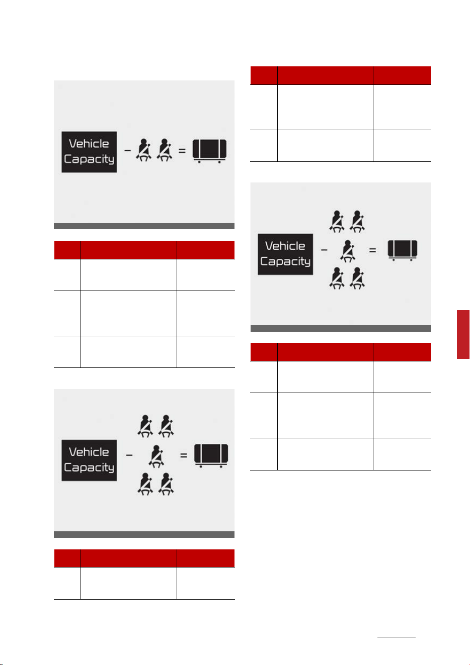
235
6
6
Driving your vehicle Vehicle load limit
Example 1
Example 2
Example 3
Refer to your vehicle's tire and load
-
ing information label for specific
information about your vehicle's
capacity weight and seating posi
-
tions. The combined weight of the
driver, passengers and cargo should
never exceed your vehicle's capac
-
ity weight.
Item Description Total
A
Vehicle Capacity
Weight
849 lbs.
(385 kg)
B
Subtract Occupant
Weight
150 lbs. (68 kg)2
300 lbs.
(136 kg)
C
Available Cargo and
Luggage weight
549 lbs.
(249 kg)
Item Description Total
A
Vehicle Capacity
Weight
849 lbs.
(385 kg)
ODEEV078137NR
ODEEV078138NR
B
Subtract Occupant
Weight
150 lbs. (68 kg)5
750 lbs.
(340 kg)
C
Available Cargo and
Luggage weight
99 lbs.
(45 kg)
Item Description Total
A
Vehicle Capacity
Weight
849 lbs.
(385 kg)
B
Subtract Occupant
Weight
161 lbs. (73 kg)5
805 lbs.
(365 kg)
C
Available Cargo and
Luggage weight
44 lbs.
(20 kg)
Item Description Total
ODEEV078139NR
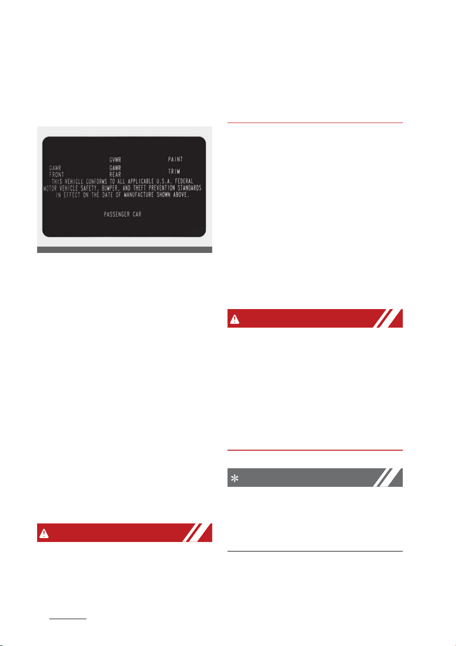
Driving your vehicle
2366
Vehicle load limit
Certification label
The certification label is located on
the driver's door sill at the center
pillar.
This label shows the maximum
allowable weight of the fully loaded
vehicle. This is called the GVWR
(Gross Vehicle Weight Rating). The
GVWR includes the weight of the
vehicle, all occupants and cargo.
This label also tells you the maxi
-
mum weight that can be supported
by the front and rear axles, called
Gross Axle Weight Rating (GAWR).
To find out the actual loads on your
front and rear axles, you need to go
to a weigh station and weigh your
vehicle. Your dealer can help you
with this. Be sure to spread out your
load equally on both sides of the
centerline.
WARNING
Over loading
Never exceed the GVWR for your
vehicle, the GAWR for either the
front or rear axle and vehicle capac
-
ity weight. Exceeding these ratings
can affect your vehicle's handling
and braking ability.
The label will help you decide how
much cargo and installed equip
-
ment your vehicle can carry.
If you carry items inside your vehicle
- like suitcases, tools, packages, or
anything else - they are moving as
fast as the vehicle. If you have to
stop or turn quickly, or if there is a
crash, the items will keep going and
can cause an injury if they strike the
driver or a passenger.
WARNING
Over loading
Do not overload your vehicle. Over
-
loading your vehicle can cause heat
buildup in your vehicle's tires and
possible tire failure, increased stop
-
ping distances and poor vehicle han
-
dling--all of which may result in a
crash.
NOTICE
Overloading your vehicle may cause
damage. Repairs would not be cov
-
ered by your warranty. Do not over
-
load your vehicle.
ODEEV078127NR

237
6
6
Driving your vehicle Vehicle weight
Vehicle weight
This section will guide you in the
proper loading of your vehicle, to
keep your loaded vehicle weight
within its design rating capability.
Properly loading your vehicle will
provide maximum return of the
vehicle design performance. Before
loading your vehicle, familiarize
yourself with the following terms
for determining your vehicle's
weight ratings, from the vehicle's
specifications and the certification
label:
Base curb weight
This is the weight of the vehicle
including a full tank of fuel and all
standard equipment. It does not
include passengers, cargo, or
optional equipment.
Vehicle curb weight
This is the weight of your new vehi
-
cle when you picked it up from your
dealer plus any aftermarket equip
-
ment.
Cargo weight
This figure includes all weight added
to the Base Curb Weight, including
cargo and optional equipment.
GAW (Gross axle weight)
This is the total weight placed on
each axle (front and rear) - including
vehicle curb weight and all payload.
GAWR (Gross axle weight rating)
This is the maximum allowable
weight that can be carried by a sin
-
gle axle (front or rear). These num
-
bers are shown on the certification
label.
The total load on each axle must
never exceed its GAWR.
GVW (Gross vehicle weight)
This is the Base Curb Weight plus
actual Cargo Weight plus passen
-
gers.
GVWR (Gross vehicle weight rating)
This is the maximum allowable
weight of the fully loaded vehicle
(including all options, equipment,
passengers and cargo). The GVWR is
shown on the certification label
located on the driver's (or front pas
-
senger's) door sill.

Driving your vehicle
2386
Overloading
Overloading
WARNING
The Gross Axle Weight Rating
(GAWR) and the Gross Vehicle
Weight Rating (GVWR) for your
vehicle are on the Certification Label
attached to the driver's (or front
passenger's) door. Exceeding these
ratings can cause an accident or
vehicle damage. You can calculate
the weight of your load by weighing
the items (and people) before put
-
ting them in the vehicle. Be careful
not to overload your vehicle

7What to do in an emergency
What to do in an emergency
Road warning............................................................................. 7-2
䳜 Hazard warning flasher......................................................... 7-2
In case of an emergency while driving.................................. 7-3
䳜 If the vehicle stalls while driving.......................................... 7-3
䳜 If the engine stalls at a crossroad or crossing .................. 7-3
䳜 If you have a flat tire while driving...................................... 7-3
If the engine will not start ...................................................... 7-4
䳜 If engine doesn't turn over or turns over slowly .............. 7-4
䳜 If engine turns over normally but does not start............. 7-4
Emergency starting.................................................................. 7-5
䳜 Jump-starting......................................................................... 7-5
䳜 Push-starting.......................................................................... 7-7
If the engine overheats............................................................ 7-8
Tire Pressure Monitoring System (TPMS)............................ 7-9
䳜 Effective use of TPMS .........................................................7-10
䳜 Low tire pressure telltale ...................................................7-11
䳜 Tire Pressure Monitoring System (TPMS)
malfunction indicator ..........................................................7-12
䳜 Tire replacement with TPMS..............................................7-13
If you have a flat tire (with spare tire) ...............................7-15
䳜 Jack and tools........................................................................7-16
䳜 Removing and storing the spare tire ................................7-17
䳜 Changing tires .......................................................................7-19
䳜 Important - use of compact spare tire ............................7-23
䳜 Jack label................................................................................7-25
Towing ......................................................................................7-26
䳜 Towing without wheel dollies when using
a towing service....................................................................7-26
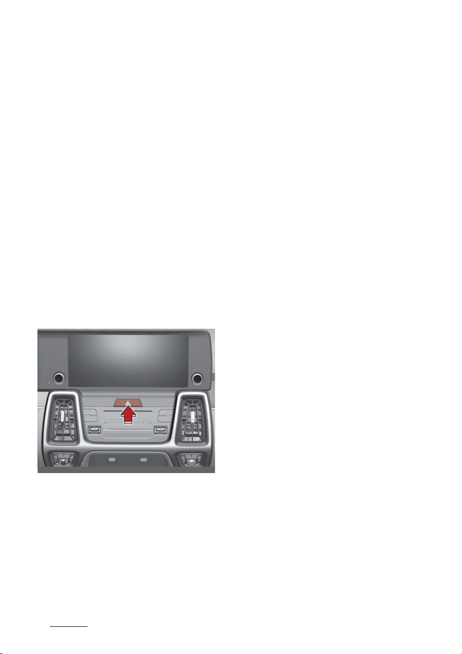
What to do in an emergency
27
Road warning
What to do in an emergency
Road warning
When in an emergency situation
occurs while driving or when you
park by the edge of the roadway,
you must alert approaching or pass
-
ing vehicles to be careful as they
pass. For this, you should use the
hazard warning flasher.
Hazard warning flasher
The hazard warning flasher serves
as a warning to other drivers to
exercise extreme caution when
approaching, overtaking, or passing
your vehicle.
It should be used whenever emer
-
gency repairs are being made or
when the vehicle is stopped near the
edge of a roadway.
Depress the flasher switch with the
ENGINE START/STOP button in any
position. The flasher switch is
located in the center fascia panel. All
turn signal lights will flash simulta
-
neously.
䳜 The hazard warning flasher oper
-
ates whether your vehicle is run
-
ning or not.
䳜 The turn signals do not work
when the hazard flasher is on.
䳜 Care must be taken when using
the hazard warning flasher while
the vehicle is being towed.
OMQ4060001

3
7
7
What to do in an emergency In case of an emergency while driving
In case of an emergency while
driving
If an emergency situation occurs
while driving, stay calm and take the
following steps.
If the vehicle stalls while driving
1. Reduce your speed gradually,
keeping a straight line.
2. Move cautiously off the road to a
safe place.
3. Turn on your hazard warning
flasher.
4. Try to start the vehicle again. If
your vehicle will not start, contact
an authorized Kia dealer or seek
other qualified assistance.
If the engine stalls at a crossroad
or crossing
䳜 If the engine stalls at a crossroad
or crossing, set the shift lever in
the N (Neutral) position and then
push the vehicle to a safe place.
If you have a flat tire while driving
1. Take your foot off the accelerator
pedal and let the vehicle slow
down while driving straight ahead.
Do not apply the brakes immedi
-
ately or attempt to pull off the
road as this may cause a loss of
control.
2. When the vehicle has slowed to
such a speed that it is safe to do
so, brake carefully and pull off the
road.
3. Drive off the road as far as possi
-
ble and park on firm level ground.
If you are on a divided highway,
do not park in the median area
between the two traffic lanes.
4. When the vehicle is stopped, turn
on your emergency hazard flash
-
ers, set the parking brake and put
the transmission in P.
5. Have all passengers get out of the
vehicle. Be sure they all get out on
the side of the vehicle that is
away from traffic.
6. When changing a flat tire, follow
the instruction provided later in
this section.
NOTICE
If there was a check engine light and
loss of power or stall and if safe to
do so, wait at least 10 seconds to
restart the vehicle after it stalls.
This may reset the car so it will no
longer run at low power (limp home)
condition.

What to do in an emergency
47
If the engine will not start
If the engine will not start
When the engine doesn't start, first
check to see how much fuel there is
and whether the battery is dis
-
charged.
If engine doesn't turn over or turns
over slowly
1. Be sure the shift lever is in N
(Neutral) or P (Park) and the
emergency brake is set.
2. Check the battery connections to
be sure they are clean and tight.
3. Turn on the interior light. If the
light dims or goes out when you
operate the starter, the battery is
discharged.
4. Check the starter connections to
be sure they are securely tight
-
ened.
WARNING
Do not push or pull the vehicle to
start it. This could cause damage to
your vehicle. Refer to "Jump-start
-
ing" on page 7-5.
If engine turns over normally but
does not start
1. Check the fuel level and add fuel if
necessary.
2. With the ENGINE START/STOP
button in the OFF position, check
all connectors at the ignition coils
and spark plugs. Reconnect any
that may be disconnected or
loose.
3. Check the fuel line in the engine
compartment.
4. If the engine still does not start,
call an authorized Kia dealer or
seek other qualified assistance.
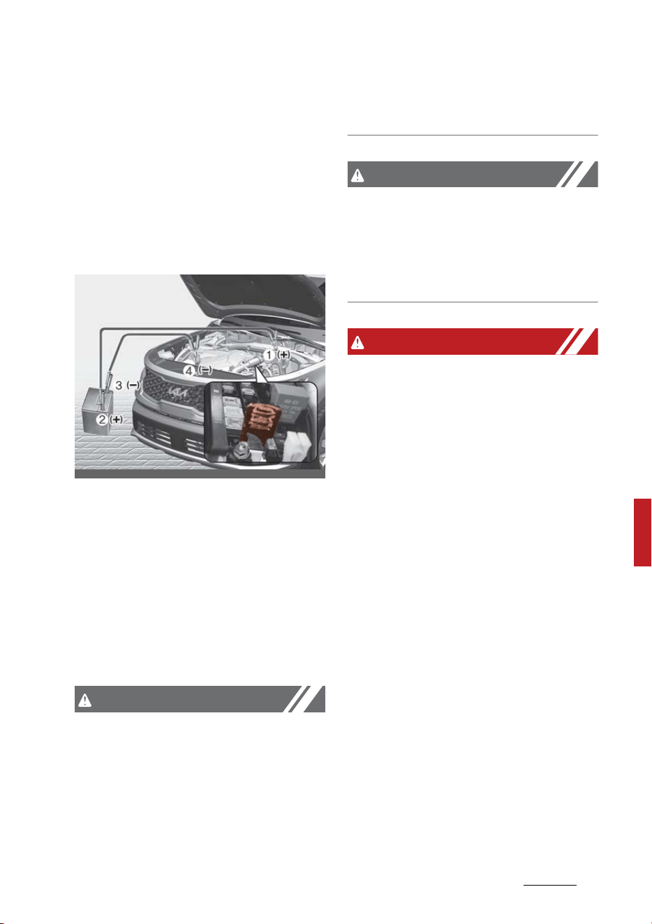
5
7
7
What to do in an emergency Emergency starting
Emergency starting
When the vehicle will not start
because of low battery power, you
may need to jump start the vehicle.
Jump-starting
Connect cables in numerical order
and disconnect in reverse order.
Jump-starting can be dangerous if
done incorrectly. Therefore, to avoid
harm to yourself or damage to your
vehicle or battery, follow these
jump-starting procedures. If in
doubt, we strongly recommend that
you have a competent technician or
towing service jump-start your
vehicle.
CAUTION
Use only a 12-volt jumper system.
You can damage a 12-volt starting
motor, ignition system, and other
electrical parts beyond repair by use
of a 24- volt power supply (either
two 12-volt batteries in series or a
24-volt motor generator set).
CAUTION
For hybrid
Do not jump start another vehicle
with your hybrid vehicle. Jump
starting another vehicle will damage
the hybrid vehicle's 12 volt battery .
WARNING
Battery
䳜 Never attempt to check the elec
-
trolyte level of the battery, as
this may cause the battery to
rupture or explode.
䳜 Keep all flames or sparks away
from the battery. The battery
produces hydrogen gas which
may explode if exposed to flame
or sparks.
If these instructions are not fol
-
lowed exactly, serious personal
injury and damage to the vehicle
may occur! If you are not sure
how to follow this procedure, seek
qualified assistance. Automobile
batteries contain sulfuric acid.
This is poisonous and highly cor
-
rosive. When jump starting, wear
protective glasses and be careful
not to get acid on yourself, your
clothing or on the vehicle.
䳜 Do not attempt to jump start the
vehicle if the discharged battery is
OMQ4H061001

What to do in an emergency
67
Emergency starting
frozen or if the electrolyte level is
low; the battery may rupture or
explode.
䳜 Do not allow the (+) and (-)
jumper cables to touch. It may
cause sparks.
䳜 The battery may rupture or
explode when you jump start with
a low or frozen battery.
WARNING
Frozen batteries
Do not attempt to jump start the
vehicle if the discharged battery is
frozen, as the battery may rupture
or explode.
WARNING
Battery
Keep all flames or sparks away from
the battery. The battery produces
hydrogen gas, which will explode if
exposed to flame or sparks.
WARNING
Battery cables
Do not connect the jumper cable
from the negative terminal of the
booster battery to the negative ter
-
minal of the discharged battery,
directly. This can cause the dis
-
charged battery to overheat and
crack or degrade. Make sure to con
-
nect one end of the jumper cable to
the negative terminal of the booster
battery, and the other end to a
metallic point, far away from the
battery.
WARNING
Sulfuric acid risk
Automobile batteries contain sulfu
-
ric acid. When jump starting your
vehicle, be careful not to get sulfuric
acid on yourself, your clothing, or on
the vehicle. This acid is poisonous
and highly corrosive.
Jump-starting
1. Make sure the booster battery is
12-volt and that its negative ter
-
minal is grounded.
If the booster battery is in
another vehicle, do not allow the
vehicles to come in contact.
2. Turn off all unnecessary electrical
loads.
3. Connect the jumper cables in the
exact sequence shown in the illus
-
tration.
1)Connect on end of a jumper
cable to the positive terminal of
the discharged battery (1).
2)Connect the other end to the
positive terminal of the booster
battery (2).
3)Proceed to connect one end of
the other jumper cable to the
negative terminal of the
booster battery (3), then the
other end to a solid, stationary,

7
7
7
What to do in an emergency Emergency starting
metallic point away from the
battery (4).
Do not allow the jumper cables
to contact anything except the
correct battery terminals or the
correct ground. Do not lean
over the battery when making
connections.
4. If connected with the other vehi
-
cle, start the vehicle with the
booster battery first and let it run
at 2,000 rpm for several minutes.
5. Start the vehicle with the dis
-
charged battery.
6. If the engine starts, disconnect
one end of the negative terminal
of the booster battery (3), then
other end of the positive terminal
of the booster battery (2) and the
discharged battery (1).
If the cause of your battery dis
-
charging is not apparent, you should
have your vehicle checked by a pro
-
fessional workshop. Kia recom
-
mends to visit an authorized Kia
dealer.
NOTICE
Battery cables
Do not connect the jumper cable
from the negative terminal of the
booster battery to the negative ter
-
minal of the discharged battery.
This can cause the discharged bat
-
tery to overheat and crack, releas
-
ing battery acid.
Make sure to connect one end of the
jumper cable to the negative termi
-
nal of the booster battery, and the
other end to a metallic point, far
away from the battery.
Push-starting
Vehicles equipped with automatic
transmission cannot be push-
started, and only jump starting can
be applied. Follow the directions in
this section for "Jump-starting" on
page 7-5.
WARNING
Tow starting vehicle
Never tow a vehicle to start it.
When the engine starts, the vehicle
can suddenly surge forward and
could cause a collision with the tow
vehicle.

8IBUUPEPJOBOFNFSHFODZ
*GUIFFOHJOFPWFSIFBUT
*GUIFFOHJOFPWFSIFBUT
*GZPVSUFNQFSBUVSFHBVHFJOEJDBUFT
PWFSIFBUJOHZPVFYQFSJFODFBMPTT
PGQPXFSPSIFBSBMPVEQJOHJOHPS
LOPDLJOHUIFFOHJOFXJMMQSPCBCMZCF
UPPIPU
*GUIJTIBQQFOTZPVTIPVME
1VMMPGGUIFSPBEBOETUPQBTTPPO
BTJUJTTBGFUPEPTP
4IJGUUIFHFBSUP11BSLBOETFU
UIFQBSLJOHCSBLF
*GUIFBJSDPOEJUJPOJOHJTPOUVSOJU
PGG
*GFOHJOFDPPMBOUJTSVOOJOHPVU
VOEFSUIFWFIJDMFPSTUFBNJT
DPNJOHPVUGSPNVOEFSOFBUIUIF
IPPETUPQUIFFOHJOF%POPU
PQFOUIFIPPEVOUJMUIFDPPMBOU
IBTTUPQQFESVOOJOHPSUIF
TUFBNJOHIBTTUPQQFE
*GUIFSFJTOPWJTJCMFMPTTPGFOHJOF
DPPMBOUBOEOPTUFBNMFBWFUIF
FOHJOFSVOOJOHBOEDIFDLUPCF
TVSFUIFFOHJOFDPPMJOHGBOJT
PQFSBUJOH
*GUIFGBOJTOPUSVOOJOHUVSO
UIFFOHJOFPGG
$IFDLUPTFFJGUIFXBUFSQVNQ
ESJWFCFMUJTNJTTJOH
*GJUJTOPUNJTTJOHDIFDLUPTFF
UIBUJUJTUJHIU
*GUIFESJWFCFMUTFFNTUPCF
TBUJTGBDUPSZDIFDLGPSDPPMBOU
MFBLJOHGSPNUIFSBEJBUPSIPTFT
PSVOEFSUIFWFIJDMF*GUIFBJS
DPOEJUJPOJOHIBECFFOJOVTFJU
JTOPSNBMGPSDPMEXBUFSUPCF
ESBJOJOHGSPNJUXIFOZPV
TUPQ
8"3/*/(
6OEFSUIFIPPE
8IJMFUIFFOHJOFJTSVOOJOH
LFFQIBJSIBOETBOEDMPUIJOH
BXBZGSPNNPWJOHQBSUT
TVDIBTUIFGBOBOEESJWF
CFMUTUPQSFWFOUJOKVSZ
*GUIFXBUFSQVNQESJWFCFMUJT
CSPLFOPSFOHJOFDPPMBOUJTMFBL
-
JOHPVUTUPQUIFFOHJOFJNNFEJ
-
BUFMZBOEDBMMUIFOFBSFTUB
QSPGFTTJPOBMXPSLTIPQGPSBTTJT
-
UBODF,JBSFDPNNFOETUPDBMMBO
BVUIPSJ[FE,JBEFBMFS
*GZPVDBOOPUGJOEUIFDBVTFPG
UIFPWFSIFBUJOHXBJUVOUJMUIF
FOHJOFUFNQFSBUVSFIBTSFUVSOFE
UPOPSNBM*GDPPMBOUIBTCFFO
MPTUDBSFGVMMZBEEDPPMBOUUPUIF
SFTFSWPJSUPCSJOHUIFGMVJEMFWFMJO
UIFSFTFSWPJSVQUPUIFIBMGXBZ
NBSL
1SPDFFEXJUIDBVUJPOLFFQJOH
BMFSUGPSGVSUIFSTJHOTPGPWFS
-
IFBUJOH*GPWFSIFBUJOHIBQQFOT
BHBJODBMMBQSPGFTTJPOBMXPSL
-
TIPQGPSBTTJTUBODF,JBSFDPN
-
NFOETUPDBMMBOBVUIPSJ[FE,JB
EFBMFS
8"3/*/(
$PPMBOUSFTFSWPJSDBQ
%POPUSFNPWFUIFFOHJOF
BOEJOWFSUFSDPPMBOUSFTFSWPJS
DBQXIFOUIFFOHJOFJTIPU
5IJTNBZSFTVMUJODPPMBOUCFJOH
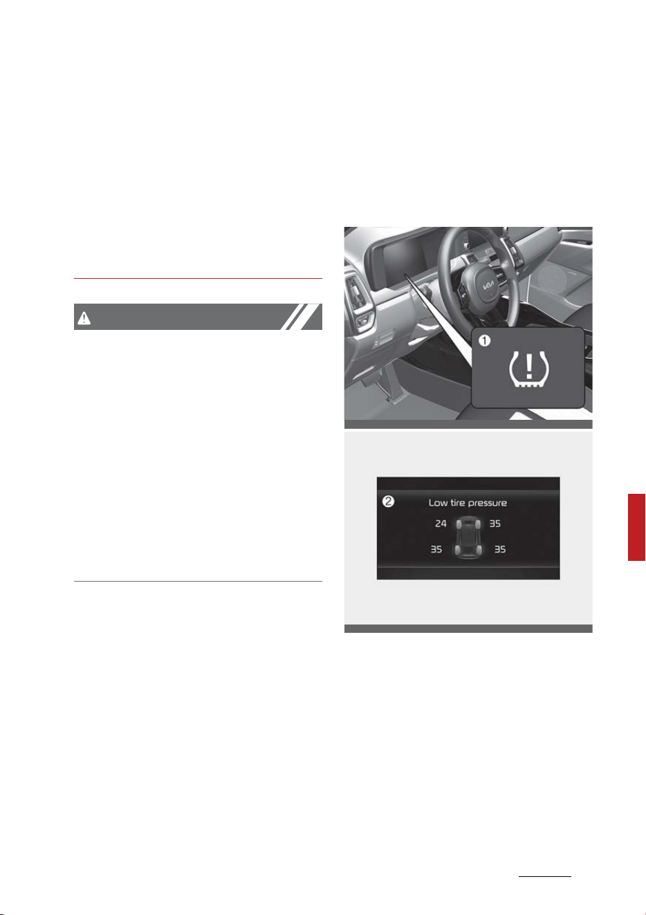
9
7
7
What to do in an emergency Tire Pressure Monitoring System (TPMS)
blown out of the opening and cause
serious burns.
If the inverter coolant is running out,
call the nearest a professional
workshop for assistance. Kia recom
-
mends to call an authorized Kia
dealer.
Use of other coolant type or water
may damage the inverter.
CAUTION
䳜 Serious loss of coolant indicates
there is a leak in the cooling sys
-
tem and this should be checked as
soon as possible. Have your vehi
-
cle checked by an authorized Kia
dealer.
䳜 When the engine overheats from
low engine coolant, suddenly add
-
ing engine coolant may cause
cracks in the engine. To prevent
damage, add engine coolant
slowly in small quantities.
Tire Pressure Monitoring Sys
-
tem (TPMS)
The Tire Pressure Monitoring Sys
-
tem (TPMS) detects the pressure of
vehicle's tires and displays it on the
LCD display.
1. Low tire pressure telltale/TPMS
malfunction indicator
2. Low tire pressure position telltale
(Shown on the LCD display)
Tire Pressure Indicator
䳜 You can check the tire pressure in
the assist mode on the cluster.
- Refer to "Driving Assist mode"
on page 5-92.
OMQ4061003
OMQ4A060055

What to do in an emergency
107
Tire Pressure Monitoring System (TPMS)
䳜 Tire pressure is displayed 1~2
minutes later after driving.
䳜 If tire pressure is not displayed
when the vehicle is stopped,
"Drive to display" message dis
-
plays. After driving, check the tire
pressure.
䳜 You can change the tire pressure
unit in the user settings mode on
the cluster.
- psi, kPa, bar (Refer to "User
settings mode" on page 5-93).
NOTICE
䳜 The tire pressure may change due
to factors such as parking condi
-
tion, driving style, and altitude
above sea level.
䳜 The tire pressure shown on the
dashboard may differ from the
tire pressure measured by tire
pressure gauge.
䳜 Low tire pressure warning may
sound when a tire's pressure unit
is equal or lower than nearby
tires. This is a normal occurrence,
which is due to the change in tire
pressure along with tire tempera
-
ture.
Effective use of TPMS
WARNING
Over-inflation or under-inflation can
reduce tire life, adversely affect
vehicle handling, and lead to sudden
tire failure that may cause loss of
vehicle control resulting in an acci
-
dent
Each tire, including the spare (if pro
-
vided), should be checked monthly
when cold and inflated to the infla
-
tion pressure recommended by the
vehicle manufacturer on the vehicle
placard or tire inflation pressure
label.
(If your vehicle has tires of a differ
-
ent size than the size indicated on
the vehicle placard or tire inflation
pressure label, you should deter
-
mine the proper tire inflation pres
-
sure for those tires.)
As an added safety feature, your
vehicle has been equipped with a
tire pressure monitoring system
(TPMS) that illuminates a low tire
pressure telltale when one or more
of your tires is significantly under-
inflated. Accordingly, when the low
tire pressure telltale illuminates, you
should stop and check your tires as
soon as possible, and inflate them to
the proper pressure. Driving on a
significantly under-inflated tire
causes the tire to overheat and can
lead to tire failure. Under-inflation
also reduces fuel efficiency and tire
tread life, and may affect the vehi
-
cle's handling and stopping ability.
Please note that the TPMS is not a
substitute for proper tire mainte
-
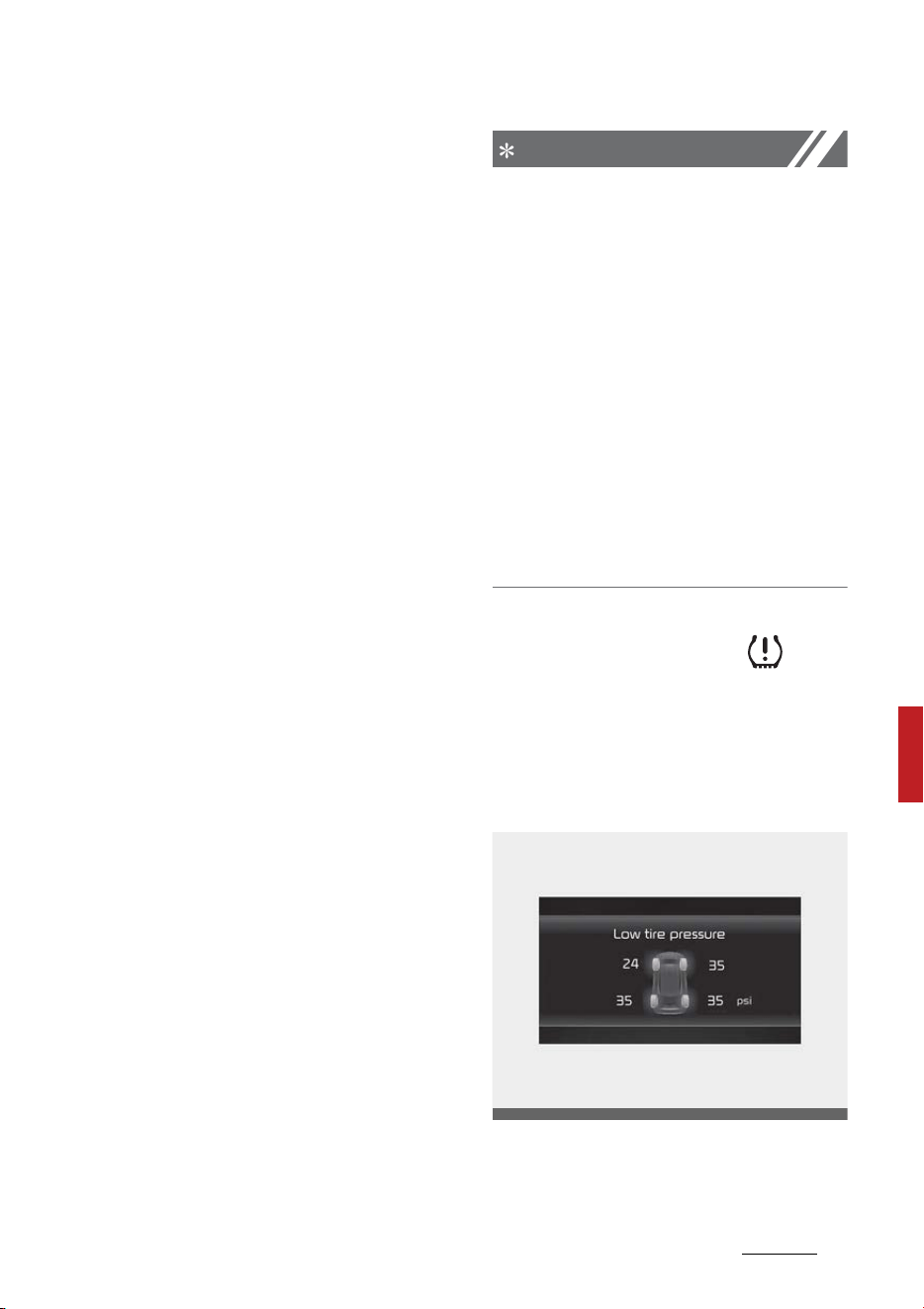
11
7
7
What to do in an emergency Tire Pressure Monitoring System (TPMS)
nance, and it is the driver's respon
-
sibility to maintain correct tire
pressure, even if under-inflation has
not reached the level to trigger illu
-
mination of the TPMS low tire pres
-
sure telltale.
Your vehicle has also been equipped
with a TPMS malfunction indicator
to indicate when the system is not
operating properly. The TPMS mal
-
function indicator is combined with
the low tire pressure telltale. When
the system detects a malfunction,
the telltale will flash for approxi
-
mately one minute and then remain
continuously illuminated. This
sequence will continue upon subse
-
quent vehicle start-ups as long as
the malfunction exists. When the
malfunction indicator is illuminated,
the system may not be able to
detect or signal low tire pressure as
intended. TPMS malfunctions may
occur for a variety of reasons,
including the installation of replace
-
ment or alternate tires or wheels on
the vehicle that prevent the TPMS
from functioning properly.
Always check the TPMS malfunction
telltale after replacing one or more
tires or wheels on your vehicle to
ensure that the replacement or
alternate tires and wheels allow the
TPMS to continue to function prop
-
erly.
NOTICE
If any of the below happens, have
the system checked by an autho
-
rized Kia dealer.
1. The low tire pressure telltale/
TPMS malfunction indicator does
not illuminate for 3 seconds when
the ENGINE START/STOP button
is turned to the ON position or
engine is running.
2. The TPMS malfunction indicator
remains illuminated after blinking
for approximately 1 minute.
3. The Low tire pressure position
telltale remains illuminated.
Low tire pressure telltale
Low tire pressure position telltale
When the TPMS warning indicators
are illuminated, one or more of your
tires is significantly under-inflated.
If the telltale illuminates, immedi
-
ately reduce your speed, avoid hard
cornering and anticipate increased
OMQ4040126L

What to do in an emergency
127
Tire Pressure Monitoring System (TPMS)
stopping distances. You should stop
and check your tires as soon as pos
-
sible.
Inflate the tires to the proper pres
-
sure as indicated on the vehicle's
placard or tire inflation pressure
label located on the driver's side
center pillar outer panel. If you can
-
not reach a service station or if the
tire cannot hold the newly added air,
replace the low pressure tire with
the spare tire.
Then the TPMS malfunction indica
-
tor and the Low Tire Pressure tell
-
tale may turn on and illuminate
after restarting and about 20 min
-
utes of continuous driving before
you have the low pressure tire
repaired and replaced on the vehicle.
In winter or cold weather, the low
tire pressure telltale may be illumi
-
nated if the tire pressure was
adjusted to the recommended tire
inflation pressure in warm weather.
It does not mean your TPMS is mal
-
functioning because the decreased
temperature leads to a proportional
lowering of tire pressure.
You should check the tire inflation
pressure and adjust the tires to the
recommended tire inflation pressure
when driving your vehicle in the fol
-
lowing conditions.
䳜 from a warm area to a cold area
䳜 from a cold area to a warm area
䳜 the outside temperature is
extremely high or low
When filling tires with more air, con
-
ditions to turn off the low tire pres
-
sure telltale may not be met. This is
because a tire inflator has a margin
of error in performance. The low
tire pressure telltale will be turned
off if the tire pressure is above the
recommended tire inflation pres
-
sure.
WARNING
Low pressure damage
Do not drive on low pressure tires.
Significantly low tire pressure can
cause the tires to overheat and fail,
making the vehicle unstable, result
-
ing in increased braking distances
and a loss of vehicle control.
Tire Pressure Monitoring System
(TPMS) malfunction indicator
The low tire pressure telltale will
illuminate after it blinks for approxi
-
mately one minute when there is a
problem with the TPMS.
If the system is able to correctly
detect an underinflation warning at
the same time as system failure, it
will illuminate both the TPMS mal
-
function and the low tire pressure
position telltales. For example, if the
Front Left sensor fails, the TPMS
malfunction indicator illuminates,

13
7
7
What to do in an emergency Tire Pressure Monitoring System (TPMS)
but if the Front Right, Rear Left, or
Rear Right tire is underinflated, the
low tire pressure position telltales
may illuminate together with the
TPMS malfunction indicator.
Have the system checked by an
authorized Kia dealer as soon as
possible to determine the cause of
the problem.
䳜 The TPMS malfunction indicator
may be illuminated if the vehicle is
moving around electric power
supply cables or radios transmit
-
ters such as at police stations,
government and public offices,
broadcasting stations, military
installations, airports, or trans
-
mitting towers, etc. This can
interfere with normal operation
of the TPMS.
䳜 The TPMS malfunction indicator
may illuminate if the vehicle is
equipped with snow chains or
some personal electronic devices
(such as a laptop computer,
mobile charger, remote starter or
navigation) are being used in the
vehicle. This can interfere with
normal operation of the TPMS.
Tire replacement with TPMS
If you have a flat tire, the Low Tire
Pressure telltale will come on. Have
the flat tire repaired by an autho
-
rized Kia dealer as soon as possible
or replace the flat tire with the
spare tire.
CAUTION
Repair agents
Never use a puncture-repairing
agent not approved by Kia to repair
and/or inflate a low pressure tire.
Sealant that is not approved by Kia
may damage the tire pressure sen
-
sor.
Each wheel is equipped with a tire
pressure sensor mounted inside the
tire behind the valve stem. You
must use TPMS specific wheels.
Have always your tires serviced by
an authorized Kia dealer.
Even if you replace the low pressure
tire with the spare tire, the Low Tire
Pressure telltale will remain on until
the low pressure tire is repaired and
placed on the vehicle.
After you replace the low pressure
tire with the spare tire, the TPMS
malfunction indicator may illumi
-
nate after a few minutes. This is
because the TPMS sensor mounted
on the spare wheel is not yet acti
-
vated.
Once the low pressure tire is inflated
again to the recommended pressure
and installed on the vehicle or the
TPMS sensor mounted on the
replaced spare wheel is initiated by
a professional workshop, the TPMS
malfunction indicator and the low

What to do in an emergency
147
Tire Pressure Monitoring System (TPMS)
tire pressure telltale will turn off
within a few minutes of driving.
If the indicator has not disappeared
after a few minutes of driving,
please visit an authorized Kia dealer.
If an original mounted tire is
replaced with the spare tire, the
TPMS sensor on the replaced spare
wheel should be initiated and the
TPMS sensor on the original
mounted wheel should be deacti
-
vated. If the TPMS sensor on the
original mounted wheel located in
the spare tire carrier still activates,
the Tire Pressure Monitoring Sys
-
tem may not operate properly. Have
the tire with TPMS serviced or
replaced by an authorized Kia dealer.
You may not be able to identify a
low tire by simply looking at it.
Always use a good quality tire pres
-
sure gauge to measure the tire's
inflation pressure. Please note that
a tire that is hot (from being driven)
will have a higher pressure mea
-
surement than a tire that is cold
(from sitting stationary for at least
3 hours and driven less than 1 mile
(1.6 km) during that 3 hour period).
Allow the tire to cool before mea
-
suring the inflation pressure. Always
be sure the tire is cold before inflat
-
ing to the recommended pressure.
A cold tire means the vehicle has
been sitting for 3 hours and driven
for less than 1 mile (1.6 km) in that
3 hour period.
Never use tire sealant if your vehicle
is equipped with a TPMS. The liquid
sealant can damage the tire pres
-
sure sensors.
䳜 The TPMS cannot alert you to
severe and sudden tire damage
caused by external factors such
as nails or road debris.
䳜 If you feel any vehicle instability,
immediately take your foot off
the accelerator, apply the brakes
gradually and with light force, and
slowly move to a safe position off
the road.
NOTICE
Protecting TPMS
Tampering with, modifying, or dis
-
abling the Tire Pressure Monitoring
System (TPMS) components may
interfere with the system's ability
to warn the driver of low tire pres
-
sure conditions and/or TPMS mal
-
functions. Tampering with,
modifying, or disabling the Tire
Pressure Monitoring System (TPMS)
components may void the warranty
for that portion of the vehicle.
This device complies with Part 15
of the FCC rules.
Operation is subject to the following
three conditions:

15
7
7
What to do in an emergency If you have a flat tire (with spare tire)
1. This device may not cause harm
-
ful interference.
2. This device must accept any
interference received, including
interference that may cause
undesired operation.
3. Changes or modifications not
expressly approved by the party
responsible for compliance could
void the user's authority to oper
-
ate the device.
If you have a flat tire (with
spare tire) (if equipped)
If you have a flat tire, you can
change the flat tire to a spare tire
using tools.
WARNING
Driving on a flat tire will cause per
-
manent damage to the tire. Re-
inflating a tire after it has been
driven on while severely underin
-
flated or flat may cause a blowout
and a serious crash. Never attempt
to re-inflate a tire that has been
driven on while severely underin
-
flated or flat. In this case, repair or
replace the flat tire as soon as pos
-
sible.
WARNING
Changing a tire can be dangerous.
Follow the instructions in this sec
-
tion when changing a tire to reduce
the risk of serious injury or death.
CAUTION
Be careful as you use the jack han
-
dle to stay clear of the flat end. The
flat end has sharp edges that could
cause cuts.
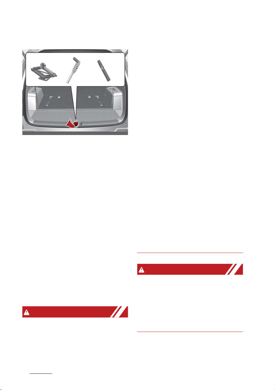
What to do in an emergency
167
If you have a flat tire (with spare tire)
Jack and tools
The jack, jack handle, wheel lug nut
wrench are stored in the luggage
compartment.
Pull up the luggage box cover to
reach this equipment.
1. Jack
2. Wheel lug nut wrench
3. Socket (if equipped)
Jacking instructions
The jack is provided for emergency
tire changing only.
䳜 To prevent the jack from "rattling"
while the vehicle is in motion,
store it properly.
䳜 Follow jacking instructions to
reduce the possibility of personal
injury.
WARNING
Changing tires
䳜 Never attempt vehicle repairs in
the traffic lanes of a public road
or highway.
䳜 Always move the vehicle com
-
pletely off the road and onto the
shoulder before trying to change
a tire. The jack should be used on
firm level ground. If you cannot
find a firm level place off the road,
call a towing service company for
assistance.
䳜 Be sure to use the correct front
and rear jacking positions on the
vehicle; never use the bumpers or
any other part of the vehicle for
jacking support.
䳜 The vehicle can roll off the jack
causing serious injury or death.
䳜 Do not go under a vehicle that is
supported by a jack.
䳜 Do not start or run the engine
while the vehicle is on the jack.
䳜 Do not allow anyone to remain in
the vehicle while it is on the jack.
䳜 Make sure any children present
are in a secure place, away from
the road and from the vehicle to
be raised with the jack.
WARNING
Tire jack
Do not place any portion of your
body under a vehicle that is only
supported by a jack since the vehicle
can easily roll off the jack. Use vehi
-
cle support stands.
OMQ4PH040485L
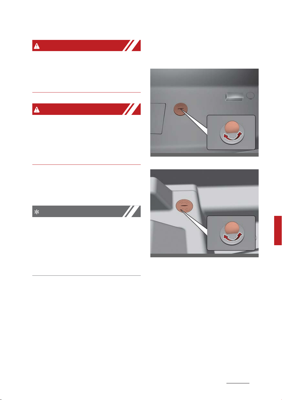
17
7
7
What to do in an emergency If you have a flat tire (with spare tire)
WARNING
Changing tires
Never attempt vehicle repairs in the
traffic lanes of a public road or high
-
way.
WARNING
Running vehicle on jack
Do not start or run the engine of the
vehicle while the vehicle is on the
jack as this may cause the vehicle to
fall off the jack.
To prevent the jack from "rattling"
while the vehicle IS in motion, store
it properly.
NOTICE
Retreaded tires
Possibly substantial variations in the
design and age of the tire casing
structures can limit service life and
have a negative impact on road
safety.
Removing and storing the spare
tire
Hybrid vehicle
Plug-in hybrid vehicle
Your spare tire is stored underneath
your vehicle, directly below the
cargo area.
To remove the spare tire:
1. Open the liftgate.
2. Find the spare tire fixing bolt
cover and remove the cover.
If necessary, separate the tool
case only after removing the
clamp.
OMQ4060039L
OMQ4PH060012L
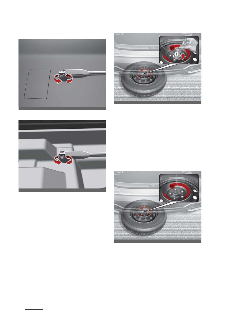
What to do in an emergency
187
If you have a flat tire (with spare tire)
Hybrid vehicle
Plug-in hybrid vehicle
3. Connect the socket and wheel lug
nut wrench.
4. Use the wheel lug nut wrench to
loosen the bolt enough to lower
the spare tire.
Turn the wrench counterclockwise
until the spare tire reaches the
ground.
5. After the spare tire reaches the
ground, continue to turn the
wrench counterclockwise, and
draw the spare tire outside. Never
rotate the wrench excessively,
otherwise the spare tire carrier
may be damaged.
6. Remove the retainer (1) from the
center of the spare tire.
To store the spare tire:
1. Lay the tire on the ground with
the valve stem facing up.
2. Place the wheel under the vehicle
and install the retainer (1)
through the wheel center.
OMQ4060040L
OMQ4PH060013L
OMQ4060041L
OMQ4060042L
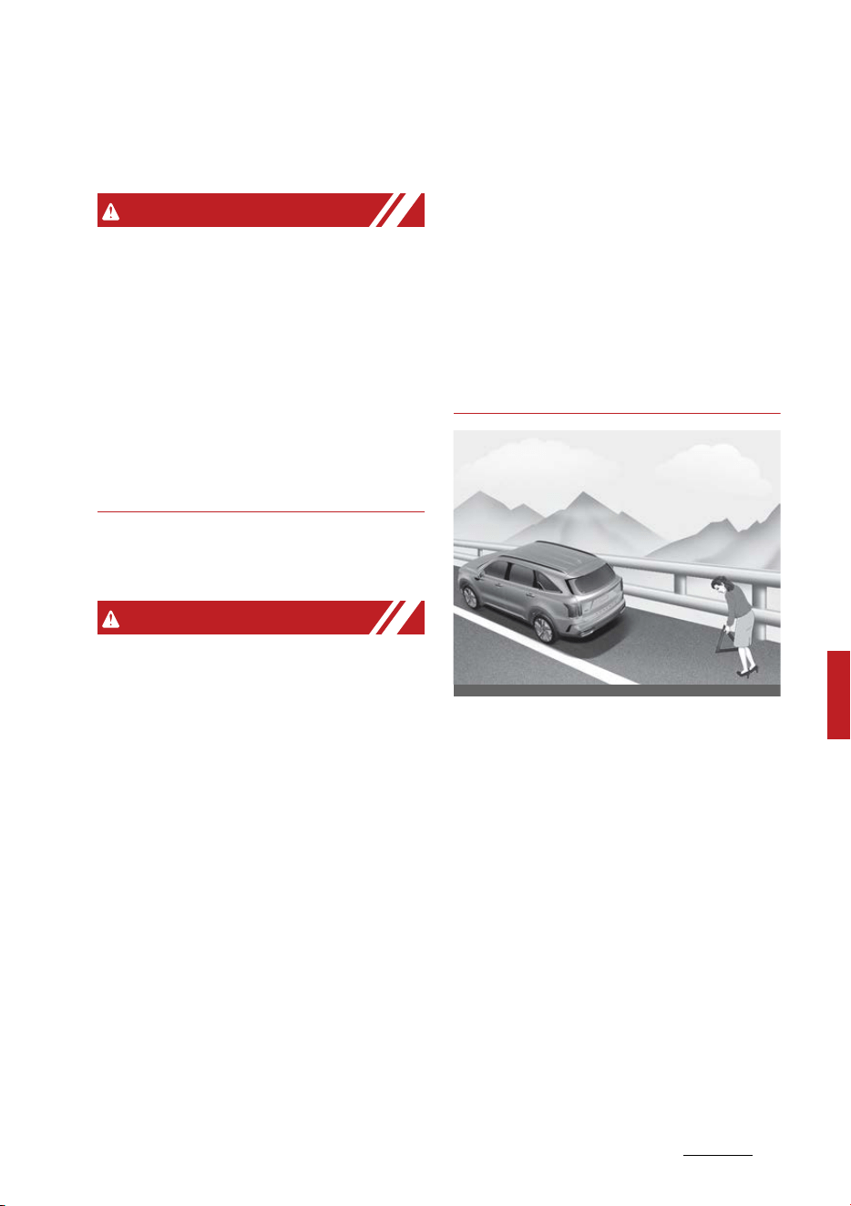
19
7
7
What to do in an emergency If you have a flat tire (with spare tire)
3. Turn the wrench clockwise until it
clicks.
WARNING
Touching surface of the luggage
room floor
Do not touch the metal surface of
the luggage room floor while the
engine is operating or hot. Doing so
could result in serious bodily injury.
Turn the engine off and wait until it
cools down or wear gloves to
remove the spare tire from the lug
-
gage room.
Changing tires
WARNING
A vehicle can slip or roll off of a jack
causing serious injury or death to
you or those nearby. Take the fol
-
lowing safety precautions:
䳜 Never place any portion of your
body under a vehicle that is sup
-
ported by a jack.
䳜 NEVER attempt to change a tire in
the lane of traffic. ALWAYS move
the vehicle completely off the
road on level, firm ground away
from traffic before trying to
change a tire. If you cannot find a
level, firm place off the road, call a
towing service for assistance.
䳜 Be sure to use the jack provided
with the vehicle.
䳜 ALWAYS place the jack on the des
-
ignated jacking positions on the
vehicle and NEVER on the bum
-
pers or any other part of the
vehicle for jacking support.
䳜 Do not start or run the engine
while the vehicle is on the jack.
䳜 Do not allow anyone to remain in
the vehicle while it is on the jack.
䳜 Keep children away from the road
and the vehicle.
1. Park on a level surface and apply
the parking brake firmly.
2. Shift the gear to P (Park), apply
the parking brake, and turn the
engine OFF.
3. Activate the hazard warning
flasher.
OMQ4061043L
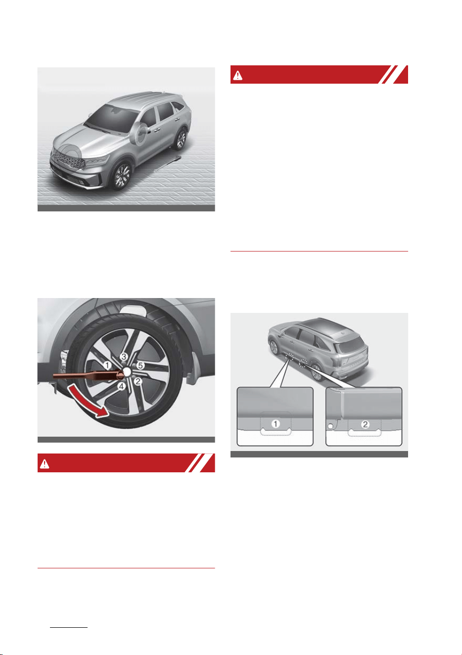
What to do in an emergency
207
If you have a flat tire (with spare tire)
4. Remove the wheel lug nut
wrench, jack, and spare tire from
the vehicle.
5. Block both the front and rear of
wheel that is diagonally opposite
the jack position.
WARNING
Jack location
To reduce the possibility of injury,
be sure to only use the jack provided
with the vehicle in the correct jack
position; never use any other part of
the vehicle for jack support.
WARNING
Changing a tire
䳜 To prevent vehicle movement
while changing a tire, always set
the parking brake fully, and
always block the wheel diagonally,
opposite the wheel being
changed.
䳜 We recommend that the wheels
of the vehicle be blocked, and that
no person remain in a vehicle that
is being jacked.
6. Loosen the wheel lug nuts coun
-
terclockwise one turn each, but do
not remove any nut until the tire
has been raised off the ground.
OMQ4061033L
OMQ4060034L
OMQ4061036L
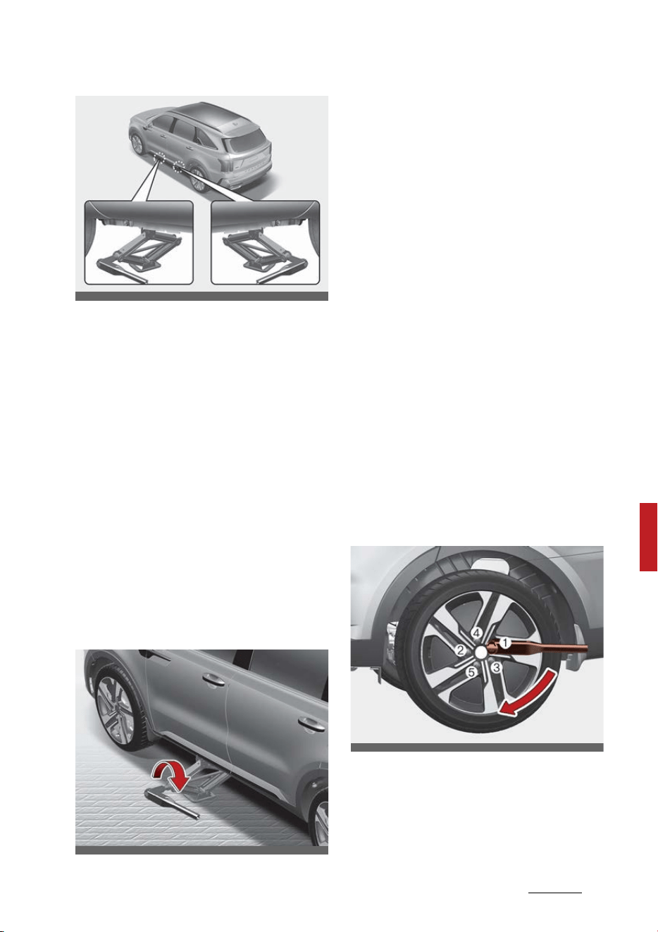
21
7
7
What to do in an emergency If you have a flat tire (with spare tire)
7. Place the jack at the front(1) or
rear(2) jacking position closest to
the tire you are changing. Place
the jack at the designated loca
-
tions under the frame. The jack
-
ing positions are plates welded to
the frame with two tabs and a
raised dot to index with the jack.
8. Insert the wheel lug nut wrench
into the jack and turn it clockwise,
raising the vehicle until the tire
just clears the ground. This mea
-
surement is approximately1.2
inches (30 mm). Before removing
the wheel lug nuts, make sure the
vehicle is stable and that there is
no chance for movement or slip
-
page.
9. Loosen the wheel nuts and
remove them with your fingers.
Slide the wheel off the studs and
lay it flat so it cannot roll away.
To put the wheel on the hub, pick
up the spare tire, line up the holes
with the studs and slide the wheel
onto them.
If this is difficult, tip the wheel
slightly and get the top hole in the
wheel lined up with the top stud.
Then jiggle the wheel back and
forth until the wheel can be slid
over the other studs.
10.To reinstall the wheel, hold it on
the studs, put the wheel nuts on
the studs and tighten them finger
tight. Jiggle the tire to be sure it is
completely seated, then tighten
the nuts as much as possible with
your fingers again.
11.Lower the vehicle to the ground
by turning the wheel nut wrench
counterclockwise.
Then position the wrench as
shown in the drawing and tighten
the wheel nuts. Be sure the
socket is seated completely over
the nut. Do not stand on the
OMQ4061035L
OMQ4PH060014L
OMQ4060038L

What to do in an emergency
227
If you have a flat tire (with spare tire)
wrench handle or use an exten
-
sion pipe over the wrench handle.
Go around the wheel tightening
every other nut until they are all
tight. Then double-check each nut
for tightness. After changing
wheels, have the system checked
by a professional workshop. Kia
recommends to visit an autho
-
rized Kia dealer.
WARNING
Installing a wheel
䳜 When you install a wheel, always
remove any corrosion, dirt or for
-
eign materials present on the
mounting surfaces of the wheel
or the surface of the wheel hub,
brake drum or brake disc that
contacts the wheel. Make sure to
secure any fasteners that attach
the rotor to the hub so they do
not interfere with the mounting
surfaces of the wheel. Installing
wheels without correct metal-to-
metal contact at the wheel
mounting surfaces can cause the
wheel nuts to loosen and the
wheel to come off while your
vehicle is in motion, resulting in
loss of vehicle control, personal
injury or death.
䳜 Make sure the wheel makes good
contact with the hub when
installed. If the contact of the
mounting surface between the
wheel and hub is not good, the
wheel nuts could come loose and
cause the loss of a wheel. Loss of
a wheel may result in loss of con
-
trol of the vehicle.
Wheel nut tightening torque:
Steel wheel & aluminum alloy wheel:
11~13kgfm (79~94lbfft)
If you have a tire gauge, remove the
valve cap and check the air pressure.
If the pressure is lower than recom
-
mended, drive slowly to the nearest
service station and inflate to the
correct pressure. If it is too high,
adjust it until it is correct. Always
reinstall the valve cap after checking
or adjusting tire pressure. If the cap
is not replaced, air may leak from
the tire. If you lose a valve cap, buy
another and install it as soon as
possible.
After you have changed wheels,
always secure the flat tire in its
place and return the jack and tools
to their proper storage locations.
CAUTION
Reusing lug nuts
Make certain during wheel removal
that the same nuts that were
removed are reinstalled - or, if
replaced, that nuts with metric
threads and the same chamfer con
-
figuration are used. Your vehicle has
metric threads on the wheel studs
and nuts. Installation of a non-met
-

23
7
7
What to do in an emergency If you have a flat tire (with spare tire)
ric thread nut on a metric stud will
not secure the wheel to the hub
properly and will damage the stud
so that it must be replaced.
Note that most lug nuts do not have
metric threads. Be sure to use
extreme care in checking for thread
style before installing aftermarket
lug nuts or wheels. If in doubt, con
-
sult an authorized Kia dealer.
WARNING
Wheel studs
If the studs are damaged, they may
lose their ability to retain the wheel.
This could lead to the loss of the
wheel and a collision resulting in
serious injuries.
WARNING
Never use oil or grease on bolts or
nuts because the nuts might come
loose. The vehicle's wheel could fall
off, causing a crash.
Important - use of compact spare
tire (if equipped)
Your vehicle is equipped with a com
-
pact spare tire. This compact spare
tire takes up less space than a regu
-
lar-size tire. This tire is smaller than
a conventional tire and is designed
for temporary use only.
䳜 You should drive carefully when
the compact spare is in use. The
compact spare should be replaced
by the proper conventional tire
and rim at the first opportunity.
䳜 The operation of this vehicle is
not recommended with more than
one compact spare tire in use at
the same time.
WARNING
Spare tire
The compact spare tire is for emer
-
gency use only. Do not operate your
vehicle on this compact spare at
speeds over 50 mph (80 km/h). The
original tire should be repaired or
replaced as soon as possible to avoid
failure of the spare, possibly leading
to bodily injury or death.
The compact spare should be
inflated to 60 psi (420 kPa).
NOTICE
Check the inflation pressure after
installing the spare tire. Adjust it to
the specified pressure, as neces
-
sary.
When using a compact spare tire,
observe the following precautions:
䳜 Under no circumstances should
you exceed 50 mph (80 km/h); a
higher speed could damage the
tire.

What to do in an emergency
247
If you have a flat tire (with spare tire)
䳜 Ensure that you drive slowly
enough for the road conditions to
avoid all hazards. Any road haz
-
ard, such as a pothole or debris,
could seriously damage the com
-
pact spare.
䳜 Any continuous road use of this
tire could result in tire failure, loss
of vehicle control, and possible
personal injury.
䳜 Do not exceed the vehicle's maxi
-
mum load rating or the load-car
-
rying capacity shown on the
sidewall of the compact spare
tire.
䳜 Avoid driving over obstacles. The
compact spare tire diameter is
smaller than the diameter of a
conventional tire and reduces the
ground clearance approximately 1
inch (25 mm), which could result
in damage to the vehicle.
䳜 Do not take this vehicle through
an automatic vehicle wash while
the compact spare tire is installed.
䳜 Do not use tire chains on the
compact spare tire. Because of
the smaller size, a tire chain will
not fit properly. This could dam
-
age the vehicle and result in loss
of the chain.
䳜 Do not use the compact spare tire
on any other vehicle because this
tire has been designed especially
for your vehicle.
䳜 The compact spare tire's tread life
is shorter than a regular tire.
Inspect your compact spare tire
regularly and replace worn com
-
pact spare tires with the same
size and design, mounted on the
same wheel.
䳜 The compact spare tire should not
be used on any other wheels, nor
should standard tires, snow tires,
wheel covers or trim rings be used
with the compact spare wheel. If
such use is attempted, damage to
these items or other vehicle com
-
ponents may occur.
䳜 Do not use more than one com
-
pact spare tire at a time.
䳜 Do not tow a trailer while the
compact spare tire is installed.
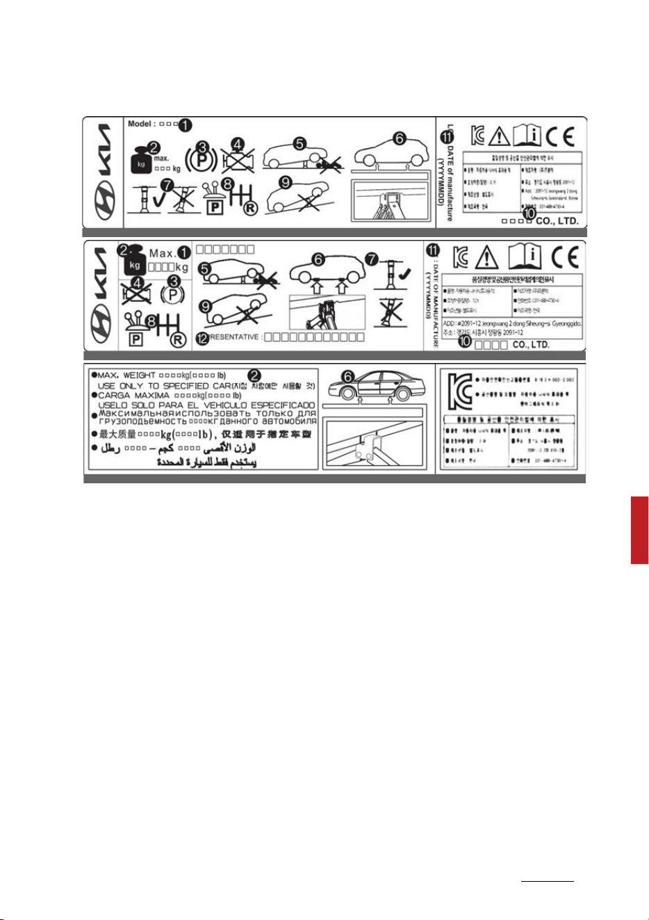
25
7
7
What to do in an emergency If you have a flat tire (with spare tire)
Jack label
* The actual Jack label in the vehicle may differ from the illustration. For
more detailed specifications, refer to the label attached to the jack.
1. Model Name
2. Maximum allowable load
3. When using the jack, set your parking brake.
4. When using the jack, stop the engine.
5. Do not get under a vehicle that is supported by a jack.
6. The designated locations under the frame
7. When supporting the vehicle, the base plate of jack must be vertical under
the lifting point.
8. Move the shift position to the P (Park) position on vehicles.
9. The jack should be used on firm level ground.
10.Jack manufacturer
11.Production date
12.Representative company and address
OHYK060001
OHYK060005
OHYK064002
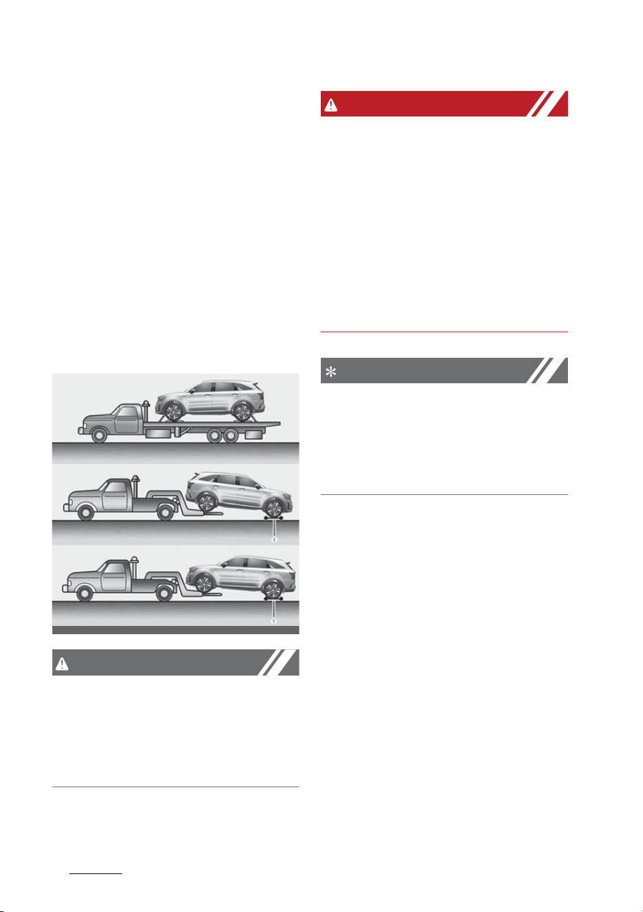
What to do in an emergency
267
Towing
Towing
Towing service
If emergency towing is necessary,
have it done by authorized Kia
dealer or a commercial tow-truck
service.
Proper lifting and towing proce
-
dures are necessary to prevent
damage to the vehicle. The use of
wheel dollies (1) or flatbed is recom
-
mended.
CAUTION
The AWD vehicle should never be
towed with the wheels on the
ground. This can cause serious
damage to the transmission or the
AWD system.
WARNING
Side and curtain air bag
If your vehicle is equipped with side
and curtain air bag, set the ENGINE
START/STOP button to ACC position
when the vehicle is being towed.
The side and curtain air bag may
deploy when the ENGINE START/
STOP button to ON position and the
rollover sensor detects the situation
as a rollover.
NOTICE
If the EPB does not release nor
-
mally, take your vehicle to an
authorized Kia dealer by loading the
vehicle on a flatbed tow truck and
have the system checked.
Towing without wheel dollies when
using a towing service
When towing your vehicle in an
emergency without wheel dollies:
1. Set the ignition switch or ENGINE
START/STOP button to ACC posi
-
tion.
2. Place the shift lever in N (Neutral).
3. Release the parking brake.
OMQ4H060008
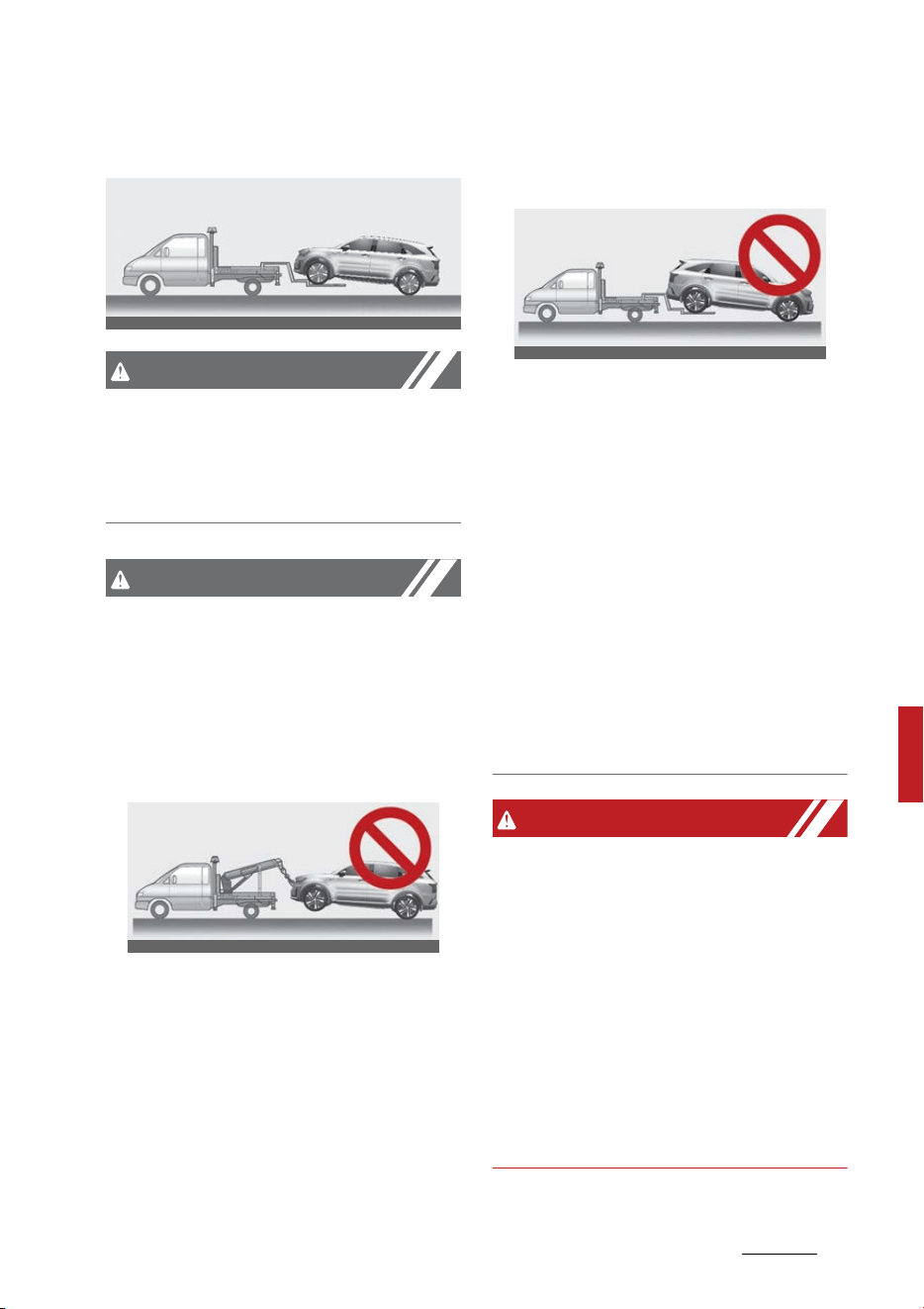
27
7
7
What to do in an emergency Towing
2-wheel drive vehicle (front wheel
drive)
CAUTION
Towing gear position
Failure to shift to N (Neutral) may
cause internal damage to the vehi
-
cle.
CAUTION
䳜 If any of the loaded wheels or
suspension components are dam
-
aged or the vehicle is being towed
with the front wheels on the
ground, use a towing dolly under
the front wheels.
䳜 Do not tow the vehicle backwards
with the front wheels on the
ground, as this may cause dam
-
age to the transmission.
2-wheel drive vehicle (front wheel
drive)
䳜 Attaching straps to the chassis,
suspension or other parts of the
body can cause damage.
䳜 Do not tow with sling-type equip
-
ment. Use wheel lift or flatbed
equipment.
䳜 Do not tow the vehicle with four
wheels in contact with the ground
if it is the vehicle equipped with
AT or DCT. Otherwise, the trans
-
mission will be seriously damaged.
Also, make sure not to tow the
vehicle connecting it with other
vehicles including camper vans.
WARNING
䳜 If you tow the vehicle while the
front wheels are touching the
ground, the vehicle motor may
generate electricity and the
motor components may be dam
-
aged or a fire may occur.
䳜 When a vehicle fire occurs due to
the battery, there is a risk of a
second fire. Contact the fire
department when towing the
vehicle.
OMQ4061014
OMQ4H060010
OMQ4H060011


8Maintenance
Maintenance
Engine compartment ............................................................... 8-5
Maintenance services............................................................... 8-6
Owner maintenance ................................................................. 8-8
䳜 Owner maintenance schedule .............................................. 8-8
Scheduled maintenance service...........................................8-10
䳜 Scheduled maintenance service precaution ....................8-10
Explanation of scheduled maintenance items...................8-16
䳜 Engine oil and filter .............................................................. 8-16
䳜 Hybrid Starter & Generator (HSG) belt.............................8-16
䳜 Fuel filter ...............................................................................8-16
䳜 Fuel lines, fuel hoses and connections..............................8-17
䳜 Vapor hose and fuel filler cap.............................................8-17
䳜 Air cleaner filter....................................................................8-17
䳜 Spark plugs ............................................................................8-17
䳜 Cooling system......................................................................8-17
䳜 Coolant/inverter coolant .....................................................8-17
䳜 Automatic transmission fluid .............................................8-17
䳜 Brake hoses and lines ..........................................................8-18
䳜 Brake fluid .............................................................................8-18
䳜 Brake discs, pads, calipers and rotors. .............................8-18
䳜 Suspension mounting bolts ................................................8-18
䳜 Steering gear box, linkage & boots/lower arm ball joint8-18
䳜 Drive shafts and boots ........................................................8-18
䳜 Air conditioning refrigerant ................................................8-18
䳜 Checking fluid levels .............................................................8-18
䳜 Propeller shaft ......................................................................8-19
Engine oil ..................................................................................8-19
䳜 Checking the engine oil level...............................................8-19
䳜 Changing the engine oil and filter......................................8-20

8 Maintenance
Coolant......................................................................................8-22
䳜 Checking the engine coolant level......................................8-22
䳜 Checking the inverter coolant level ...................................8-24
Hybrid starter & generator (HSG) belt................................8-26
䳜 Checking the Hybrid Starter & Generator (HSG) belt.....8-26
Brake fluid ................................................................................8-26
䳜 Checking the brake fluid level.............................................8-26
Washer fluid.............................................................................8-28
䳜 Checking the washer fluid level..........................................8-28
Air cleaner filter ......................................................................8-29
䳜 Replacing air cleaner filter ..................................................8-29
Climate control air filter ........................................................8-30
䳜 Filter inspection ....................................................................8-30
Wiper blades ............................................................................8-32
䳜 Blade inspection....................................................................8-32
䳜 Blade replacement................................................................8-32
䳜 Replacing rear wiper blade..................................................8-34
Battery .....................................................................................8-35
䳜 For best battery service......................................................8-35
䳜 Battery recharging...............................................................8-37
䳜 Reset items ...........................................................................8-38
Tires and wheels .....................................................................8-38
䳜 Checking tire inflation pressure .........................................8-39
䳜 Tire rotation ..........................................................................8-40
䳜 Wheel alignment and tire balance .....................................8-41
䳜 Tire replacement ..................................................................8-41
䳜 Wheel replacement ..............................................................8-42
䳜 Tire traction...........................................................................8-42

8Maintenance
䳜 Tire maintenance ................................................................. 8-42
䳜 Tire sidewall labeling............................................................8-43
䳜 Tire terminology and definitions .......................................8-46
䳜 All season tires......................................................................8-48
䳜 Summer tires ........................................................................8-49
䳜 Snow tires..............................................................................8-49
䳜 Tire chains .............................................................................8-49
䳜 Radial-ply tires .....................................................................8-50
Fuses.........................................................................................8-51
䳜 Inner panel fuse replacement ............................................8-53
䳜 Engine compartment fuse replacement ..........................8-54
䳜 Fuse/relay panel description ..............................................8-55
Light bulbs................................................................................8-65
䳜 Bulb replacement precaution .............................................8-65
䳜 Light bulb position (Front) .................................................. 8-66
䳜 Light bulb position (Rear)....................................................8-67
䳜 Light bulb position (Side).....................................................8-68
䳜 Replacing headlamp (Low beam/High beam),
position lamp/daytime running lamp, turn signal lamp
(LED type) ..............................................................................8-68
䳜 Replacing front turn signal lamp (Bulb type) ..................8-69
䳜 Replacing front fog lamp (LED type) ................................8-70
䳜 Replacing front side marker lamp bulb (LED type) ........8-70
䳜 Replacing side repeater lamp (LED type).........................8-70
䳜 Replacing stop and taillamp (Bulb type)...........................8-71
䳜 Replacing rear turn signal lamp (Bulb type) ....................8-72
䳜 Replacing rear turn signal lamp, stop and taillamp,
rear side marker lamp (LED type) .....................................8-73
䳜 Replacing reversing lamp (bulb type)................................8-73
䳜 Replacing high mounted stop lamp (LED type)...............8-74

8 Maintenance
䳜 Replacing license plate lamp (LED type)...........................8-75
䳜 Replacing map lamp (Bulb type) ........................................8-75
䳜 Replacing map lamp (LED type) .........................................8-76
䳜 Replacing room lamp (Bulb type) ......................................8-76
䳜 Replacing personal lamp (LED type)..................................8-77
䳜 Replacing vanity mirror lamp (Bulb type) ........................8-77
䳜 Replacing glove box lamp (Bulb type) ...............................8-78
䳜 Replacing luggage lamp (Bulb type) ..................................8-78
䳜 Replacing luggage lamp (LED type)...................................8-79
Appearance care .....................................................................8-79
䳜 Exterior care..........................................................................8-79
䳜 Interior care...........................................................................8-85
Emission control system .......................................................8-87
䳜 Procedure for entering forced engine activation
mode .......................................................................................8-90
California perchlorate notice.................................................8-91
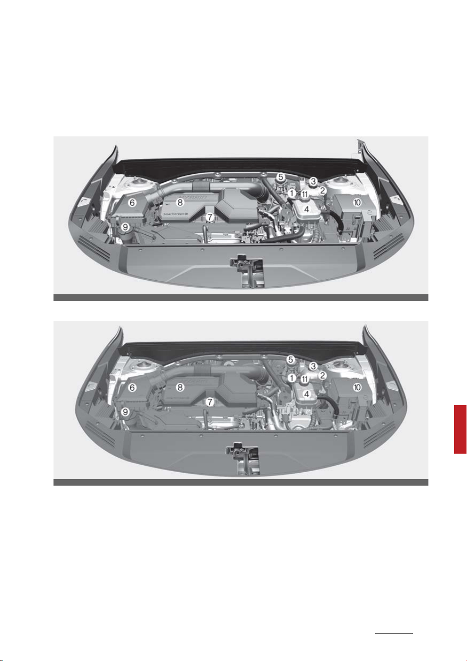
5
8
8
Maintenance Engine compartment
Maintenance
Engine compartment
Smartstream G1.6 T-GDi HEV
Smartstream G1.6 T-GDi PHEV
* The actual engine room in the vehicle may differ from the illustration.
1. Electronic Control Unit (ECU)
2. Engine coolant reservoir
3. Engine coolant reservoir cap
4. Inverter coolant reservoir
5. Brake fluid reservoir
6. Air cleaner
7. Engine oil dipstick
8. Engine oil filler cap
9. Windshield washer fluid reservoir
10.Fuse box
11.Inverter coolant reservoir cap
OMQ4H070021
OMQ4PH070021L

Maintenance
68
Maintenance services
Maintenance services
You should exercise the utmost care
to prevent damage to your vehicle
and injury to yourself whenever
performing any maintenance or
inspection procedures.
Should you have any doubts con
-
cerning the inspection or servicing
of your vehicle, have an authorized
Kia dealer perform this work.
An authorized Kia dealer has fac
-
tory-trained technicians and genu
-
ine Kia parts to service your vehicle
properly. For expert advice and
quality service, see an authorized
Kia dealer.
Inadequate, incomplete or insuffi
-
cient servicing may result in opera
-
tional problems with your vehicle
that could lead to vehicle damage,
an accident, or personal injury.
Owner's responsibility
NOTICE
Maintenance Service and Record
Retention are the owner's responsi
-
bility.
You should retain documents that
show proper maintenance has been
performed on your vehicle in accor
-
dance with the scheduled mainte
-
nance service charts shown on the
following pages. You need this
information to establish your com
-
pliance with the servicing and main
-
tenance requirements of your
vehicle warranties.
Detailed warranty information is
provided in your Warranty & Con
-
sumer Information manual.
Repairs and adjustments required
as a result of improper maintenance
or a lack of required maintenance
are not covered.
Have your vehicle maintained and
repaired by an authorized Kia dealer.
Authorized Kia dealers meet Kia's
high service quality standards and
receive technical support from Kia in
order to provide you with a high
level of service satisfaction.
NOTICE
NHTSA Safety Corrosion Alert
The National Highway Traffic Safety
Administration (NHTSA) has issued
a general warning to all vehicle own
-
ers of all brands regarding the risks
associated with vehicle underbody
corrosion. From your initial pur
-
chase, take the following steps to
prevent unsafe corrosion damage to
your vehicle:
䳜 Wash the undercarriage of your
vehicle regularly during the winter
and whenever your vehicle has
been exposed to such salts or
chemicals.

7
8
8
Maintenance Maintenance services
䳜 Do a thorough washing of the
undercarriage at the end of the
winter.
䳜 Use professional service techni
-
cians or governmental inspection
stations to annually inspect for
corrosion.
䳜 Immediately seek an inspection of
your vehicle if you become visu
-
ally aware of corrosion flaking or
scaling or if you become aware of
a change in vehicle performance,
such as soft or spongy brakes,
fluids leaking, impairment of
directional control, suspension
noises or rattling metal straps.
䳜 NHTSA further advises that after
a vehicle is 7 years old, it is essen
-
tial that you take these indicated
maintenance steps to ensure that
you protect yourself from unsafe
corrosion conditions.
Owner maintenance precautions
Improper or incomplete service may
result in problems. This section
gives instructions only for the main
-
tenance items that are easy to per
-
form.
As explained earlier in this section,
several procedures can be done only
by an authorized Kia dealer with
special tools.
NOTICE
Improper owner maintenance during
the warranty period may affect
warranty coverage. For details, read
the separate Warranty & Consumer
Information manual provided with
the vehicle. If you're unsure about
any servicing or maintenance proce
-
dure, have it done by an authorized
Kia dealer.
WARNING
Maintenance work
Do not wear jewelry or loose cloth
-
ing while working under the hood of
your vehicle with the engine run
-
ning. These items can become
entangled in moving parts, if you
must run the engine while working
under the hood, make certain that
you remove all jewelry (especially
rings, bracelets, watches, and neck
-
laces) and all neckties, scarves, and
similar loose clothing before getting
near cooling fans.
WARNING
Touching metal parts
Do not touch metal parts (including
strut bars) while the vehicle is oper
-
ating or hot. Doing so could result in
serious bodily injury. Turn the vehi
-
cle off and wait until the metal parts

Maintenance
88
Owner maintenance
cool down to perform maintenance
work on the vehicle.
Owner maintenance
The following lists are vehicle checks
and inspections that should be per
-
formed by the owner or an autho
-
rized Kia dealer at the frequencies
indicated to help ensure safe,
dependable operation of your vehi
-
cle.
Any adverse conditions should be
brought to the attention of your
dealer as soon as possible.
These owner maintenance checks
are generally not covered by war
-
ranties and you may be charged for
labor, parts and lubricants used.
Owner maintenance schedule
When you stop for fuel:
䳜 Check the coolant level in coolant
reservoir.
䳜 Check the windshield washer fluid
level.
䳜 Look for low or under-inflated
tires.
䳜 Check if the front of the radiator
and condenser are clean and not
blocked with leaves, dirt or insects
etc. If any of the above parts are
extremely dirty or you are not
sure of their condition, take your
vehicle to an authorized Kia
dealer.

.BJOUFOBODF 0XOFSNBJOUFOBODF
8"3/*/(
)PUDPPMBOU
#FDBSFGVMXIFODIFDLJOH
ZPVSFOHJOFDPPMBOUMFWFM
XIFOUIFFOHJOFJTIPU
4DBMEJOHIPUDPPMBOUBOETUFBNNBZ
CMPXPVUVOEFSQSFTTVSF
8IJMFPQFSBUJOHZPVSWFIJDMF
䳜 /PUFBOZDIBOHFTJOUIFTPVOEPG
UIFFYIBVTUPSBOZTNFMMPG
FYIBVTUGVNFTJOUIFWFIJDMF
䳜 $IFDLGPSWJCSBUJPOTJOUIFTUFFS
-
JOHXIFFM/PUJDFBOZJODSFBTFE
TUFFSJOHFGGPSUPSMPPTFOFTTJOUIF
TUFFSJOHXIFFMPSDIBOHFJOJUT
TUSBJHIUBIFBEQPTJUJPO
䳜 /PUJDFJGZPVSWFIJDMFDPOTUBOUMZ
UVSOTTMJHIUMZPSQVMMTUPPOFTJEF
XIFOUSBWFMJOHPOTNPPUIMFWFM
SPBE
䳜 8IFOTUPQQJOHMJTUFOBOEDIFDL
GPSVOVTVBMTPVOETQVMMJOHUPPOF
TJEFJODSFBTFECSBLFQFEBMUSBWFM
PSIBSEUPQVTICSBLFQFEBM
䳜 *GBOZTMJQQJOHPSDIBOHFTJOUIF
PQFSBUJPOPGZPVSUSBOTNJTTJPO
PDDVSTUBLFZPVSWFIJDMFUPBO
BVUIPSJ[FE,JBEFBMFS
䳜 $IFDLUIFBVUPNBUJDUSBOTNJTTJPO
11BSLGVODUJPO
䳜 $IFDLUIFQBSLJOHCSBLF
䳜 $IFDLGPSGMVJEMFBLTVOEFSZPVS
WFIJDMFXBUFSESJQQJOHGSPNUIF
BJSDPOEJUJPOJOHTZTUFNEVSJOHPS
BGUFSVTFJTOPSNBM
"UMFBTUNPOUIMZ
䳜 $IFDLUIFDPPMBOUMFWFMJOUIF
DPPMBOUSFTFSWPJS
䳜 $IFDLUIFPQFSBUJPOPGBMMFYUFSJPS
MJHIUTJODMVEJOHUIFTUPQMJHIUT
UVSOTJHOBMTBOEIB[BSEXBSOJOH
GMBTIFST
䳜 $IFDLUIFJOGMBUJPOQSFTTVSFTPGBMM
UJSFTJODMVEJOHUIFTQBSFGPSUJSFT
UIBUBSFXPSOTIPXVOFWFOXFBS
PSBSFEBNBHFE
䳜 $IFDLGPSMPPTFXIFFMMVHOVUT
"UMFBTUPODFFWFSZNPOUIT
䳜 $IFDLUIFSBEJBUPSIFBUFSBOEBJS
DPOEJUJPOJOHIPTFTGPSMFBLTPS
EBNBHF
䳜 $IFDLUIFXJOETIJFMEXBTIFS
TQSBZBOEXJQFSPQFSBUJPO$MFBO
UIFXJQFSCMBEFTXJUIDMFBODMPUI
EBNQFOFEXJUIXBTIFSGMVJE
䳜 $IFDLUIFIFBEMBNQBMJHONFOU
䳜 $IFDLUIFNVGGMFSFYIBVTUQJQFT
TIJFMETBOEDMBNQT
䳜 $IFDLUIFMBQTIPVMEFSCFMUTGPS
XFBSBOEGVODUJPO
"UMFBTUPODFBZFBS
䳜 $MFBOUIFCPEZBOEEPPSESBJO
IPMFT
䳜 -VCSJDBUFUIFEPPSIJOHFTBOE
DIFDLUIFIPPEIJOHFT
䳜 -VCSJDBUFUIFEPPSBOEIPPEMPDLT
BOEMBUDIFT
䳜 -VCSJDBUFUIFEPPSSVCCFSXFBUI
-
FSTUSJQT
䳜 $IFDLUIFBJSDPOEJUJPOJOHTZTUFN

Maintenance
108
Scheduled maintenance service
䳜 Inspect and lubricate automatic
transmission linkage and controls.
䳜 Clean the battery and terminals.
䳜 Check the brake fluid level.
䳜 Visually inspect steering, suspen
-
sion, and chassis components for
damaged, loose, or missing parts
or signs of wear.
Scheduled maintenance service
Scheduled maintenance service
precaution
Follow the Normal Maintenance
Schedule if the vehicle is usually
operated where none of the follow
-
ing conditions apply. If any of the
following conditions apply, follow
the Maintenance Under Severe
Usage Conditions.
䳜 Repeated driving short distance
of less than 5 miles (8 km) in nor
-
mal temperature or less than 10
miles (16 km) in freezing tem
-
perature
䳜 Extensive engine idling or low
speed driving for long distances
䳜 Driving on rough, dusty, muddy,
unpaved, graveled or salt-spread
roads
䳜 Driving in areas using salt or other
corrosive materials or in very cold
weather
䳜 Driving in heavy dust condition
䳜 Driving in heavy traffic area
䳜 Driving on uphill, downhill, or
mountain road repeatedly
䳜 Using for towing or camping and
driving with loading on the roof
䳜 Driving as a patrol car, taxi, other
commercial use of vehicle towing
䳜 Frequently driving under high
speed or rapid acceleration/decel
-
eration
䳜 Frequently driving in stop-and-go
condition

11
8
8
Maintenance Scheduled maintenance service
If your vehicle is operated in any of
the prior listed conditions, you
should inspect, replace or refill more
frequently, using the severe usage
maintenance schedule instead of
the normal usage maintenance
schedule.
NOTICE
After 10 years or 100,000 miles
(150,000 km), we recommend to
use severe maintenance schedule.
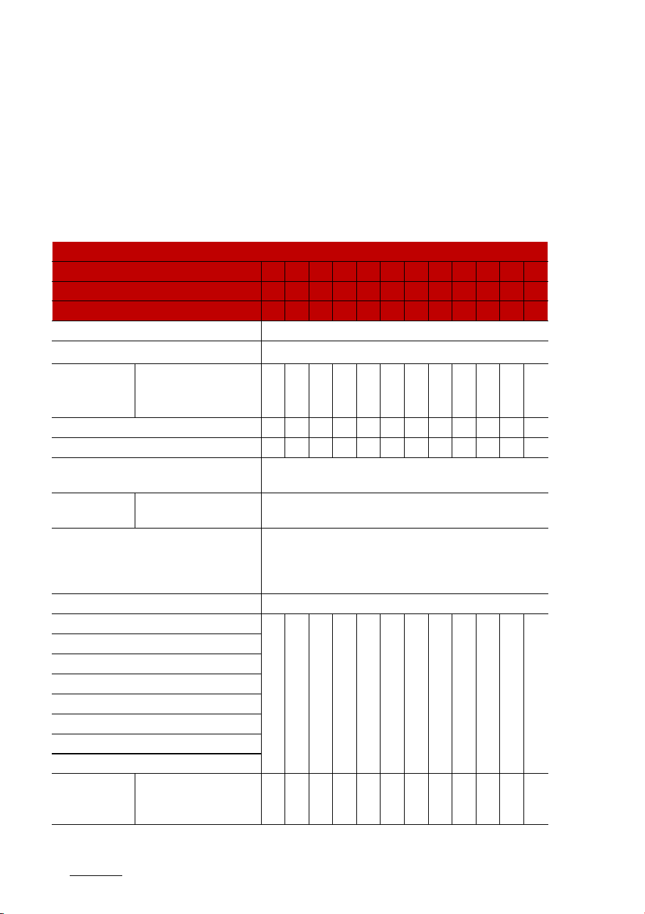
Maintenance
128
Scheduled maintenance service
Normal maintenance schedule
The following maintenance services must be performed to ensure good
emission control and performance. Keep receipts for all vehicle services to
protect your warranty. Where both mileage and date are shown, the fre
-
quency of service is determined by whichever occurs first.
I: Inspect and if necessary, adjust, correct, clean or replace.
R: Replace or change.
Number of months or driving distance, whichever comes first
Months 12 24 36 48 60 72 84 96 108 120 132 144
Miles1,000 8 16 24 32 40 48 56 64 72 80 88 96
Km1,000 13 26 39 52 65 78 91 104 117 130 143 156
Tire rotation Rotate every 8,000 miles (13,000 km)
Fuel additives
*1
Add every 8,000 miles (13,000 km) or 12 months
Engine oil and
engine oil filter
*2
Smartstream G1.6 T-
GDi HEV/PHEV
R R R R R R R R R R R R
Climate control air filter I R I R I R I R I R I R
Air cleaner filter (Engine) I I R I I R I I R I I R
Brake fluid
Inspect every 8,000 miles (13,000 km) or 12 months,
Replace every 48,000 miles (78,000 km) or 48 months
Spark plugs
Smartstream G1.6 T-
GDi HEV/PHEV
Replace every 48,000 miles (78,000 km)
Coolant (Engine)
*3
At first, replace at 120,000 miles (195,000 km) or 120
months
After that, replace every 24,000 miles (39,000 km) or 24
months
Coolant (Inverter)*4 Replace every 32,000 miles (52,000 km) or 36 months
Air conditioner refrigerant
I I I I I I I I I I I I
Air conditioner compressor
Battery condition
Brake discs and pads
Brake lines, hoses and connections
Suspension ball joints
Steering gear rack, linkage and boots
Exhaust system
Intercooler in/
out hose, air
intake hose
Smartstream G1.6 T-
GDi HEV/PHEV
I - I - I - I - I - I -

13
8
8
Maintenance Scheduled maintenance service
*1. Fuel additives
Kia recommends that you use Tier 1
unleaded gasoline which has an
octane rating of RON (Research
Octane Number) 95/AKI (Anti Knock
Index) 91 or higher.
For customers who do not use good
quality gasolines including fuel addi
-
tives regularly, and have problems
starting or the engine does not run
smoothly, one bottle of additives
should be added to the fuel tank at
every 8,000 miles (13,000 km).
Additives are available from an
authorized Kia dealer. Do not mix
with other additives.
*2. Engine oil and engine oil filter
As it is normal for engine oil to be
consumed during driving, the engine
oil level should be checked on regular
basis.
The engine oil change interval for
normal operating conditions is
based on the use of the recom
-
mended engine specification. If the
recommended engine oil specifica
-
tion is not used, then replace the
engine oil according to the mainte
-
nance schedule under severe oper
-
ating conditions.
*3. Coolant (Engine)
When adding coolant, use only
deionized water or soft water for
your vehicle and never mix hard
Drive shaft and boots
- I - I - I - I - I - I
Propeller shaft (AWD)
Fuel tank and fuel cap
Fuel tank air filter
Fuel lines, hoses and connections
Cooling system - - - I - I - I - I - I
HSG (Hybrid Starter & Generator) belt *5
Inspect every 8,000 miles (13,000 km) or 12 months
Replace every 64,000 miles (100,000 km) or 48 months
Differential oil (rear) (AWD) *6
Inspect every 40,000 miles (65,000 km) or 48 months
Transfer case oil (AWD) *7
Automatic
transmission
(AT) fluid
Smartstream G1.6 T-
GDi HEV/PHEV
No service required
Number of months or driving distance, whichever comes first
Months 12 24 36 48 60 72 84 96 108 120 132 144
Miles1,000 8 16 24 32 40 48 56 64 72 80 88 96
Km1,000 13 26 39 52 65 78 91 104 117 130 143 156

Maintenance
148
Scheduled maintenance service
water in the coolant filled at the
factory. An improper coolant mix
-
ture can result in serious malfunc
-
tion or engine damage.
*4. Coolant (Inverter)
Recommend that the coolant be
replaced by an authorized Kia
dealer/service partner.
*5. HSG (Hybrid Starter & Genera
-
tor) belt
Inspect HSG belt for evidence of
cuts, cracks, excessive wear or oil
saturation and replace if necessary.
*6. Differential oil (rear) (AWD)
If the vehicle has been submerged in
water or in a flooded area, the fluids
should be changed as a precaution.
*7. Transfer case oil (AWD)
If the vehicle has been submerged in
water or in a flooded area, the fluids
should be changed as a precaution.
Fuel filter (Gasoline engine)
The fuel filter is considered to be
maintenance free but periodic
inspection is recommended for this
maintenance schedule depends on
fuel quality.
䳜 If there are some important
safety matters like fuel flow
restriction, surging, loss of power,
hard starting problem etc, replace
the fuel filter immediately
regardless of maintenance sched
-
ule and consult an authorized Kia
dealer for details.

15
8
8
Maintenance Scheduled maintenance service
Maintenance under severe usage conditions
I: Inspect and if necessary, adjust, correct, clean or replace.
R: Replace or change.
Severe driving conditions
A: Repeatedly driving short distance
of less than 5 miles (8 km) in normal
temperature or less than 10 miles
(16 km) in freezing temperature.
B: Extensive engine idling or low
speed driving for long distances.
C: Driving on rough, dusty, muddy,
unpaved, graveled or saltspread
roads.
D: Driving in areas using salt or
other corrosive materials or in very
cold weather
Maintenance item
Maintenance
operation
Maintenance intervals Driving condition
Engine oil and
engine oil filter
Smartstream
G1.6 T-GDi HEV/
PHEV
R
Every 5,000 miles
(8,000 km) or 6 months
A, B, C, D, E, F, G, H, I, J, K
HSG (Hybrid Starter & Generator) belt
R
Every 32,000 miles
(52,000 km) or 24
months
B, C, D, E, I, K
I
Every 8,000 miles
(13,000 km) or 12
months
Spark plugs
Smartstream
G1.6 T-GDi HEV/
PHEV
R More frequently A, B, F, G, H, I, K
Air cleaner filter R More frequently C, E
Climate control air filter R More frequently C, E, G
Automatic trans
-
mission (AT) fluid
Smartstream
G1.6 T-GDi HEV/
PHEV
R
Every 56,000 miles
(91,000 km)
A, C, F, G, H, I, J, K
Differential oil (rear) (AWD) R
Every 72,000 miles
(117,000 km)
C, E, G, H, I, J
Transfer case oil (AWD) R
Every 72,000 miles
(117,000 km)
C, E, G, H, I, J
Steering gear rack, linkage and boots I More frequently C, D, E, F, G, H, I
Suspension ball joints I More frequently C, D, E, G, H, I
Brake discs, pads and calipers I More frequently C, D, E, G, H, J, K
Drive shaft and boots I More frequently C, D, E, F, G, H, I, J
Propeller shaft (AWD) I More frequently C, D, E, F, G, H, I, J

Maintenance
168
Explanation of scheduled maintenance items
E: Driving in heavy dust condition.
F: Driving in heavy traffic area.
G: Driving on uphill, downhill, or
mountain roads repeatedly.
H: Using for towing or camping and
driving with loading on the roof.
I: Driving for patrol car, taxi, other
commercial use of vehicle towing.
J: Frequently driving under high
speed or rapid acceleration/deceler
-
ation
K: Frequently driving in stop-and-go
conditions.
Explanation of scheduled main
-
tenance items
Engine oil and filter
The engine oil and filter should be
changed at the intervals specified in
the maintenance schedule. If the
vehicle is being driven in severe con
-
ditions, more frequent oil and filter
changes are required.
Hybrid Starter & Generator (HSG)
belt
Inspect all hybrid starter & genera
-
tor belts for evidence of cuts,
cracks, excessive wear or oil satura
-
tion and replace if necessary. Hybrid
starter & generator belts should be
checked periodically for proper ten
-
sion and adjusted as necessary.
CAUTION
When you are inspecting the belt,
place the ENGINE START/STOP but
-
ton in the LOCK/OFF or ACC position.
Fuel filter
Kia gasoline vehicles are equipped
with a lifetime fuel filter that inte
-
grated with the fuel tank. Regular
maintenance or replacement is not
needed but depends on fuel quality.
If there are some important safety
matters like fuel flow restriction,
surging, loss of power, hard starting

17
8
8
Maintenance Explanation of scheduled maintenance items
problem etc, fuel filter inspection or
replace is needed.
Have the fuel filter inspected or
replaced by an authorized Kia dealer.
Fuel lines, fuel hoses and connec
-
tions
Check the fuel lines, fuel hoses and
connections for leakage and dam
-
age. Have the fuel lines, fuel hoses
and connections replaced by an
authorized Kia dealer.
Vapor hose and fuel filler cap
The vapor hose and fuel filler cap
should be inspected at those inter
-
vals specified in the maintenance
schedule. Make sure that a new
vapor hose or fuel filler cap is cor
-
rectly replaced.
Air cleaner filter
Have the air cleaner filter replaced
by an authorized Kia dealer.
Spark plugs
Make sure to install new spark plugs
of the correct heat range.
When assembling parts, be sure to
wipe the inside and outside of the
boot bottom of the ignition coil and
the insulator of the spark plug with
a soft cloth to prevent contamina
-
tion of the spark plug insulator.
WARNING
Do not disconnect and inspect spark
plugs when the engine is hot. You
may burn yourself.
Cooling system
Check the cooling system compo
-
nents, such as the radiator, coolant
reservoir, hoses and connections for
leakage and damage. Replace any
damaged parts.
Coolant/inverter coolant
The coolant should be changed at
the intervals specified in the main
-
tenance schedule.
Automatic transmission fluid
Automatic transmission fluid should
not be checked under normal usage
conditions. Have the automatic
transmission fluid changed by an
authorized Kia dealer.
NOTICE
Automatic transmission fluid color is
basically red.
As the vehicle is driven, the auto
-
matic transmission fluid will begin to
look darker. It is normal condition
and you should not judge the need
to replace the fluid based upon the
changed color.

Maintenance
188
Explanation of scheduled maintenance items
CAUTION
The use of a non-specified fluid
could result in transmission mal
-
function and failure.
Use only specified automatic trans
-
mission fluid. (Refer to "Recom
-
mended lubricants and capacities"
on page 9-8.)
Brake hoses and lines
Visually check for proper installa
-
tion, chafing, cracks, deterioration
and any leakage. Replace any dete
-
riorated or damaged parts immedi
-
ately.
Brake fluid
Check the brake fluid level in the
brake fluid reservoir. The level
should be between "MIN" and "MAX"
marks on the side of the reservoir.
Use only hydraulic brake fluid con
-
forming to DOT 4 specification.
Brake discs, pads, calipers and
rotors.
Check the pads for excessive wear,
discs for run out and wear, and cali
-
pers for fluid leakage.
Suspension mounting bolts
Check the suspension connections
for looseness or damage. Retighten
to the specified torque.
Steering gear box, linkage & boots/
lower arm ball joint
With the vehicle stopped and engine
off, check for excessive free-play in
the steering wheel.
Check the linkage for bends or dam
-
age. Check the dust boots and ball
joints for deterioration, cracks, or
damage. Replace any damaged
parts.
Drive shafts and boots
Check the drive shafts, boots and
clamps for cracks, deterioration, or
damage. Replace any damaged
parts and, if necessary, repack the
grease.
Air conditioning refrigerant
Check the air conditioning lines and
connections for leakage and dam
-
age.
Checking fluid levels
When checking engine oil, engine
coolant, brake fluid, and washer
fluid, always be sure to clean the
area around any filler plug, drain
plug, or dipstick before checking or
draining any lubricant or fluid. This
is especially important in dusty or
sandy areas and when the vehicle is
used on unpaved roads. Cleaning the
plug and dipstick areas will prevent
dirt and grit from entering the
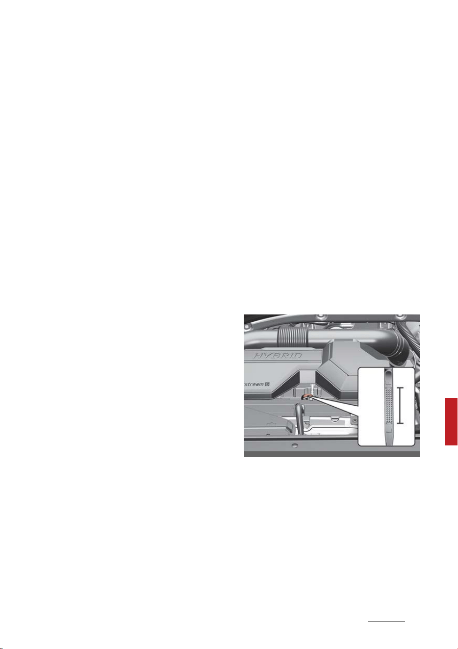
19
8
8
Maintenance Engine oil
engine and other mechanisms that
could be damaged.
Propeller shaft (if equipped)
Check the propeller shaft, boots,
clamps, rubber coupling and center
bearing rubber for cracks, deterio
-
ration, or damage. Replace any
damaged parts and if necessary,
repack the grease.
Engine oil
Checking the engine oil level
Engine oil is used for lubricating,
cooling, and operating various
hydraulic components in the engine.
Engine oil consumption while driving
is normal, and it is necessary to
check and refill the engine oil regu
-
larly. Also, check and refill the oil
level within the recommended
maintenance schedule to prevent
deterioration of oil performance.
Check the engine oil following the
below procedure.
Smartstream G1.6 T-GDi HEV/PHEV
1. Be sure the vehicle is on level
ground.
2. Start the engine and allow it to
reach normal operating tempera
-
ture.
3. Turn the engine off, remove the
oil filler cap and pull the dipstick
out. Wait for 15 minutes for the
oil to return to the oil pan.
OMQ4H070001
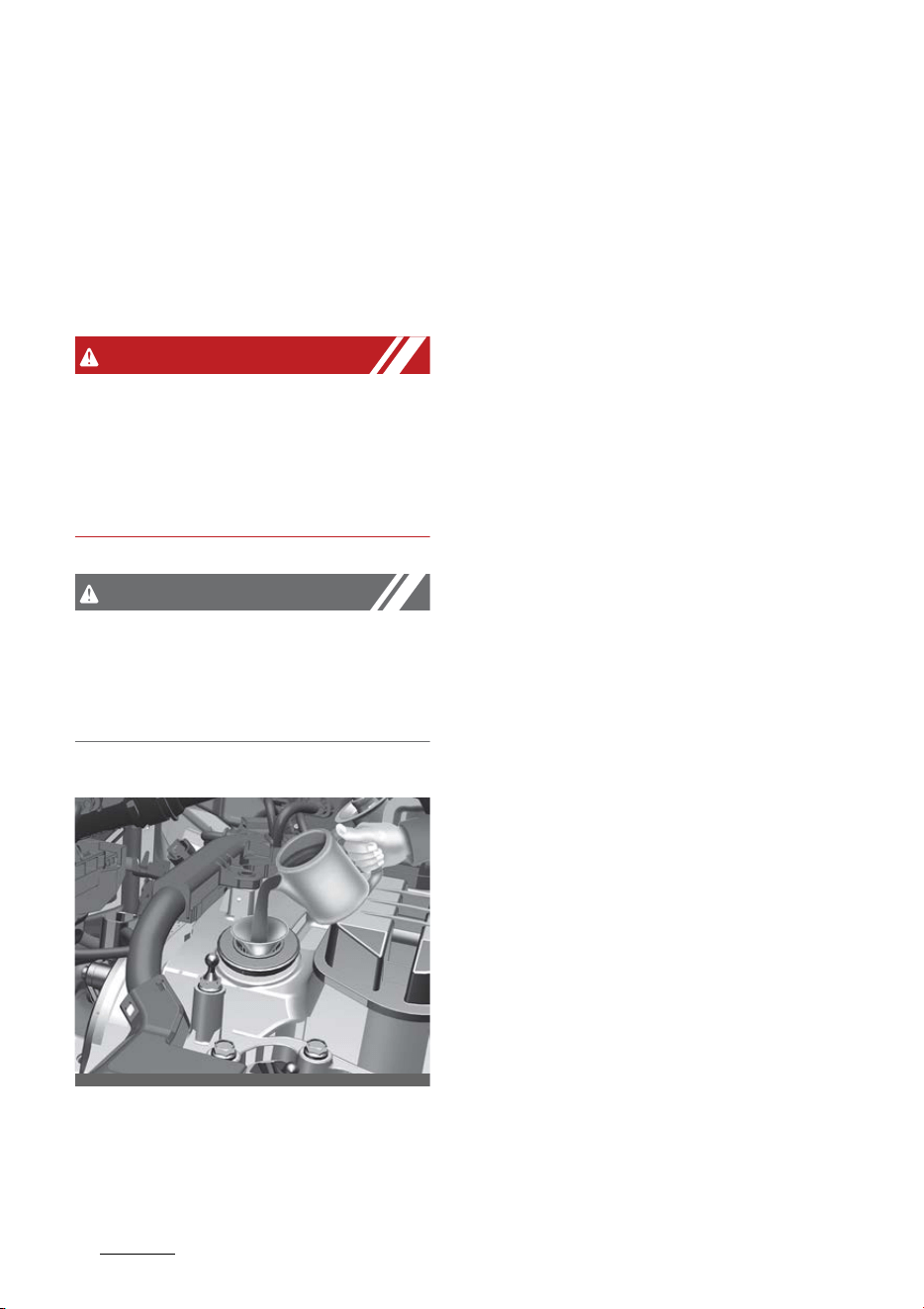
Maintenance
208
Engine oil
4. Wipe the dipstick clean and re-
insert it fully.
5. Pull the dipstick out again and
check the level. Check if the oil
level is between the F-L line, and
if it is below the L line, add enough
oil to bring the level to F line.
WARNING
Radiator hose
Be very careful not to touch the
radiator hose when checking or
adding the engine oil as it may be
hot enough to burn you.
CAUTION
When you wipe the oil level gauge,
you should wipe it with a clean cloth.
When mixed with debris, it can
cause engine damage.
Smartstream G1.6 T-GDi HEV/PHEV
Use a funnel to help prevent oil from
being spilled on engine components.
Use only the specified engine oil.
(Refer to "Recommended lubricants
and capacities" on page 9-8.)
䳜 Do not spill engine oil when adding
or changing engine oil. Wipe off
spilled oil immediately.
䳜 The engine oil consumption may
increase while you break in a new
vehicle and it will be stabilized
after driving 4,000 miles (6,000
km).
䳜 The engine oil consumption can be
affected by driving habits, climate
conditions, traffic conditions, oil
quality, etc. Therefore, it is rec
-
ommended that you inspect the
engine oil level regularly and refill
it if necessary.
Changing the engine oil and filter
Have the engine oil and filter
replaced by an authorized Kia dealer.
䳜 If the maintenance schedule to
replace engine oil is exceeded, the
engine oil performance may dete
-
riorate, and the engine condition
may be affected. Therefore,
replace the engine oil according to
the maintenance schedule.
䳜 To keep the engine in optimal
condition, use the recommended
engine oil and filter. If the recom
-
mended engine oil and filter are
not used replace it according to
the maintenance schedule under
severe usage conditions.
OMQ4H070002
21
8
8
Maintenance Engine oil
䳜 The purpose of the maintenance
schedule for engine oil replace
-
ment is to prevent oil deteriora
-
tion and it is irrelevant to oil
consumption. Check and refill
engine oil regularly.
WARNING
Used engine oil
Used engine oil may cause irritation
or cancer of the skin if left in con
-
tact with the skin for prolonged
periods of time. Used engine oil con
-
tains chemicals that have caused
cancer in laboratory animals. Always
protect your skin by washing your
hands thoroughly with soap and
warm water as soon as possible
after handling used oil. Do not leave
used engine oil within the reach of
children.
NOTICE
When the oil pressure is low due to
insufficient engine oil, the Engine Oil
Pressure ( ) warning light will
illuminate.
In addition, the enhanced engine
protection system, which limits the
engine's power is activated and the
Malfunction Indicator Lamp ( )
will illuminate when the vehicle is
driven in this state continuously.
When oil pressure is restored, the
Engine Oil Pressure warning light will
turn off and the engine power will
no longer be limited.
CAUTION
The engine oil is very hot immedi
-
ately after the vehicle has been
driven and can cause burns during
replacement. Replace the engine oil
after the engine oil has cooled down.
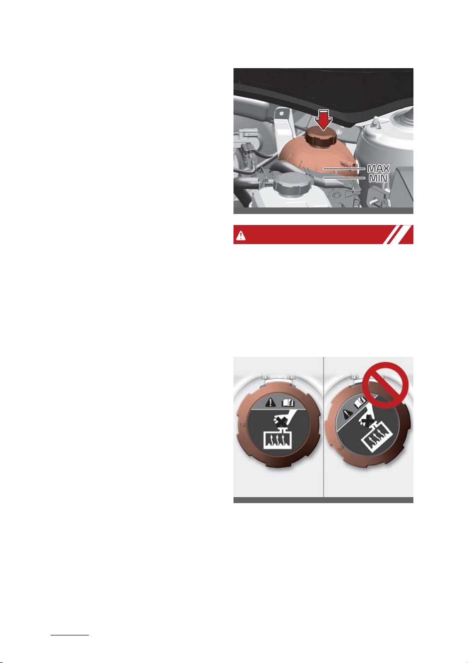
Maintenance
228
Coolant
Coolant
The high-pressure cooling system
has a reservoir filled with year
round antifreeze coolant. The reser
-
voir is filled at the factory.
Check the antifreeze protection and
coolant level at least once a year, at
the beginning of the winter season,
and before traveling to a colder cli
-
mate.
Checking the engine coolant level
When adding coolant, use only
deionized water, distilled water or
soft water for your vehicle and
never mix hard water in the coolant
filled at the factory.
䳜 An incorrect coolant mixture can
result in severe malfunction or
engine/hybrid system damage.
䳜 The engine in your vehicle has
aluminum engine parts and must
be protected by an phosphate-
based ethylene glycol coolant to
prevent corrosion and freezing.
䳜 Do not use alcohol or methanol
coolant or mix them with the
specified coolant.
䳜 Do not use a solution that con
-
tains more than 60% antifreeze
or less than 35% antifreeze,
which would reduce the effective
-
ness of the solution.
WARNING
Make sure the engine coolant reser
-
voir cap is properly closed after refill
or coolant.
Otherwise the engine could be over
-
heated while driving.
1. Check if the engine coolant reser
-
voir cap label is straight In front.
2. Make sure that the tiny protru
-
sions inside the engine coolant
reservoir cap are securely inter
-
locked.
OMQ4PH070022L
OMQ4A060054
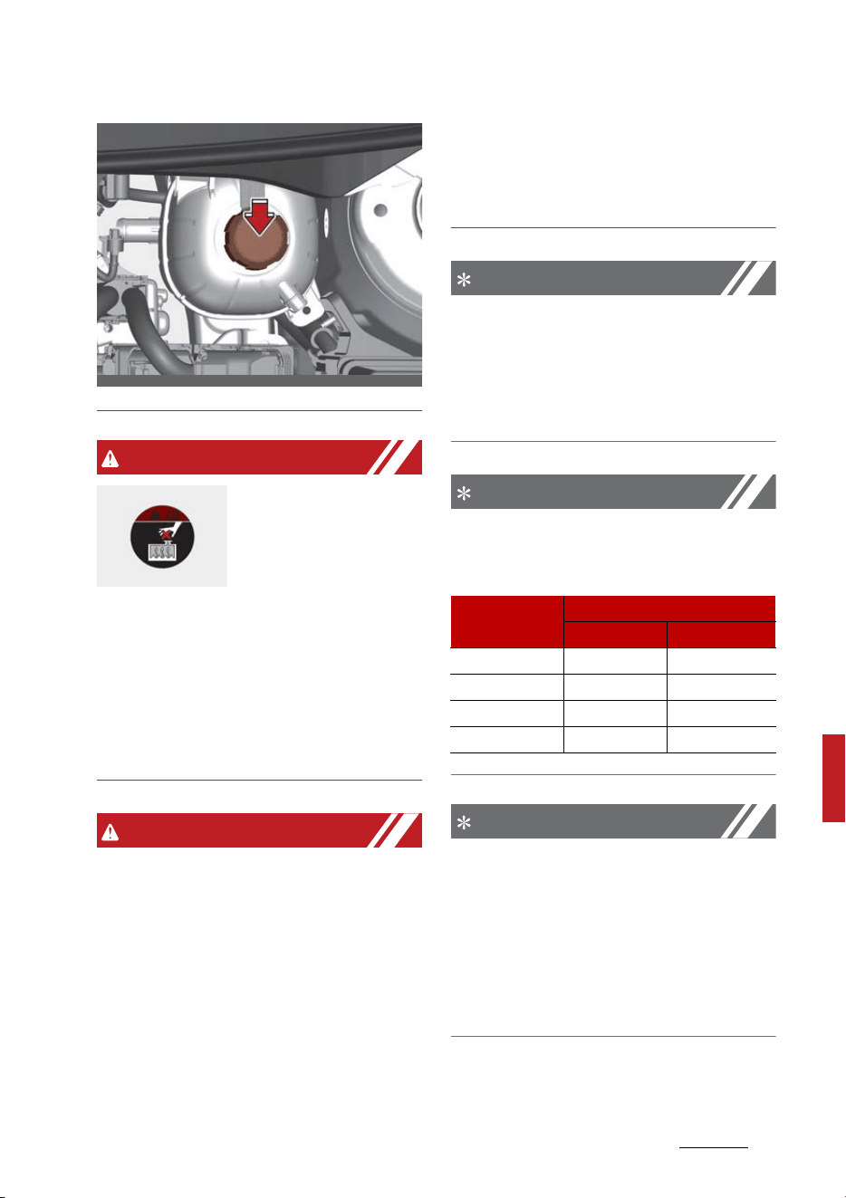
23
8
8
Maintenance Coolant
WARNING
Removing engine
coolant reservoir
cap
Never attempt to
remove the engine
coolant reservoir cap while the
engine is operating or hot. Doing so
might lead to cooling system dam
-
age and could result in serious per
-
sonal injury from escaping hot
coolant or steam.
WARNING
Turn the vehicle off and wait until
the engine cools down. Use extreme
care when removing the engine
coolant cap. Wrap a thick towel
around it, and turn it counterclock
-
wise slowly to the first stop. Step
back while the pressure is released
from the cooling system. When you
are sure all the pressure has been
released, press down on the cap,
using a thick towel, and continue
turning counterclockwise to remove
it.
NOTICE
The engine coolant level is influ
-
enced by the hybrid system tem
-
perature. Before checking or refilling
the engine coolant, turn the hybrid
vehicle off.
NOTICE
For mixture percentage, refer to the
following table.
NOTICE
To prevent damage to engine parts,
put a thick towel around the engine
coolant cap and/or inverter coolant
cap before refilling the coolant to
prevent the coolant from overflow
-
ing into engine parts, such as the
alternator.
OMQ4H070007
Ambient Tem
-
perature
Mixture Percentage (volume)
Antifreeze Water
5F (-15 C) 35 65
-13F (-25 C) 40 60
-31F (-35 C) 50 50
-49F (-45 C) 60 40
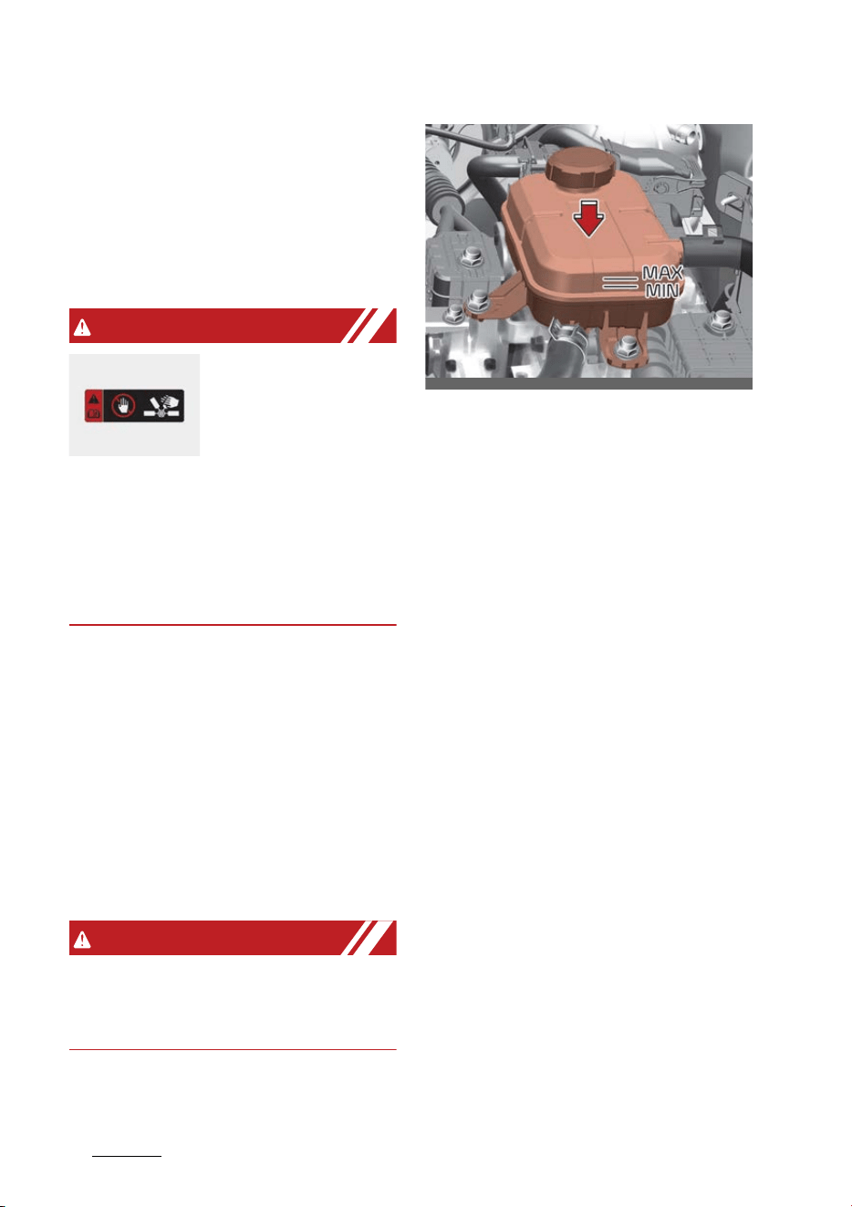
Maintenance
248
Coolant
Changing the coolant
We recommend that the coolant be
replaced by an authorized Kia dealer
according to the Maintenance
Schedule at the beginning of this
chapter.
WARNING
Cooling fan
Use caution when
working near the
blade of the cooling
fan. The electric
motor (cooling fan) is controlled by
coolant temperature, refrigerant
pressure and vehicle speed. It may
sometimes operate even when the
vehicle is not running.
Checking the inverter coolant level
If frequent additions are required,
we recommend that the system be
inspected by an authorized Kia
dealer.
The inverter coolant level should be
in between MAX and MIN when the
engine is cooled down.
WARNING
Adding other cooling substances or
water might lead to inverter cooling
system degradation or even failure.
䳜 Turn the vehicle off and wait until
it cools down.
䳜 Use extreme care when removing
the inverter coolant reservoir cap.
Wrap a thick towel around it, and
turn it counterclockwise slowly to
the first stop.
䳜 Step back while the pressure is
released from the cooling system.
䳜 When you are sure all the pres
-
sure has been released, press
down on the cap, using a thick
towel, and continue turning coun
-
terclockwise to remove it.
䳜 Check the condition and connec
-
tions of all cooling system hoses
and heater hoses.
䳜 Replace any swollen or deterio
-
rated hoses.
䳜 Check the coolant level. The cool
-
ant level should be filled between
MAX and MIN marks on the side of
the coolant reservoir when the
engine room is cool.
䳜 If the coolant level is low, add
enough specified coolant to pro
-
vide protection against freezing
OMQ4H070004
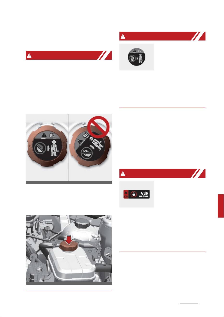
25
8
8
Maintenance Coolant
and corrosion. Bring the level to
MAX, but do not overfill.
WARNING
Make sure the inverter coolant res
-
ervoir cap is properly closed after
refill or coolant.
Otherwise the inverter could be
overheated while driving.
1. Check if the inverter coolant res
-
ervoir cap label is straight In front.
2. Maker sure that the tiny protru
-
sions inside the inverter coolant
reservoir cap are securely inter
-
locked.
WARNING
Removing inverter
coolant reservoir
cap
Never remove the
inverter coolant
reservoir cap while the engine and
radiator are hot. Hot coolant and
steam may blow out under pres
-
sure, causing serious injury.
Changing the coolant
We recommend that the coolant be
replaced by an authorized Kia dealer
according to the Maintenance
Schedule at the beginning of this
chapter.
WARNING
Cooling fan
Use caution when
working near the
blade of the cooling
fan. The electric
motor (cooling fan) is controlled by
coolant temperature, refrigerant
pressure and vehicle speed. It may
sometimes operate even when the
vehicle is not running.
OMQ4H070026
OMQ4H070006
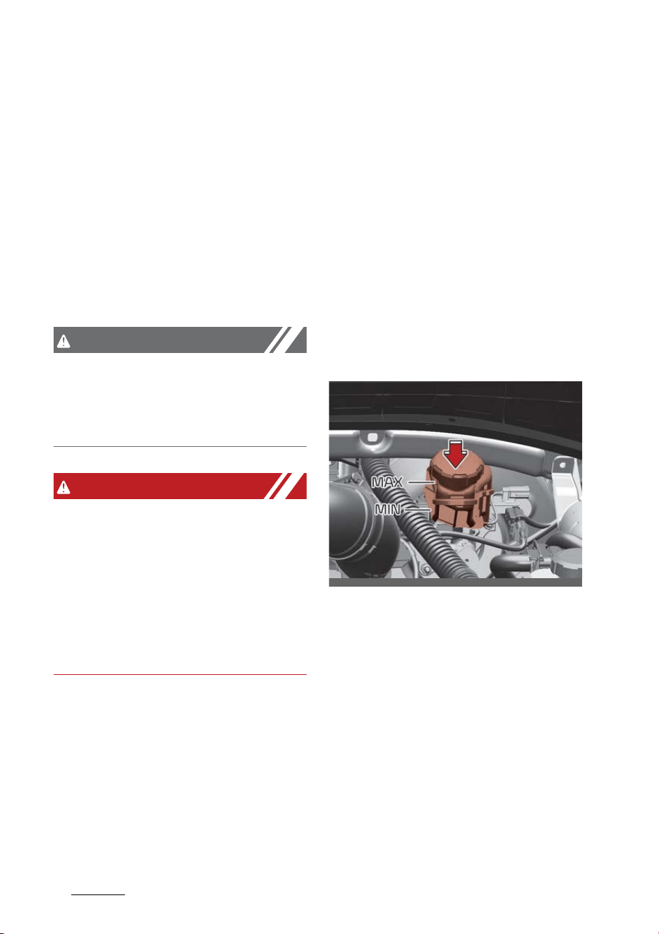
Maintenance
268
Hybrid starter & generator (HSG) belt
Hybrid starter & generator
(HSG) belt
Checking the Hybrid Starter & Gen
-
erator (HSG) belt
We recommend that you have the
Hybrid Starter & Generator (HSG)
belt inspected or replaced according
to the Maintenance Schedule in this
chapter by an authorized Kia dealer.
CAUTION
When the HSG belt is worn out or
damaged, replace the belt. Other
-
wise, it may cause engine overheat
-
ing or battery discharge.
WARNING
䳜 Turn the vehicle off while you
inspect the engine or Hybrid
Starter & Generator (HSG) belt.
Otherwise it may result in serious
injury.
䳜 Keep hands, clothing etc. away
from the Hybrid Starter & Gener
-
ator (HSG) belt
Brake fluid
The brake fluid acts to transmit
force to the brake when the driver
depresses the brake pedal. Brake
fluid must be maintained periodi
-
cally to ensure that the brakes
operate smoothly.
Checking the brake fluid level
Check the fluid level in the reservoir
periodically. The fluid level should be
between MAX and MIN marks on the
side of the reservoir.
1. Before removing the reservoir cap
and adding brake fluid, clean the
area around the reservoir cap
thoroughly to prevent brake fluid
contamination.
2. Periodically check that the fluid
level in the brake fluid reservoir is
between MIN and MAX. The level
will fall with accumulated mileage.
This is a normal condition associ
-
ated with the wear of the brake
linings.
If the fluid level is excessively low,
have the system checked by a
OMQ4070069

27
8
8
Maintenance Brake fluid
professional workshop. Kia rec
-
ommends to visit an authorized
Kia dealer.
Use only the specified brake fluid.
(Refer to "Recommended lubricants
and capacities" on page 9-8.)
Never mix different types of fluid.
WARNING
Loss of brake fluid
In the event the brake system
requires frequent additions of fluid,
have the system inspected by an
authorized Kia dealer.
WARNING
Brake fluid
When changing and adding brake
fluid, handle it carefully. Do not let it
come in contact with your eyes. If
brake fluid should come in contact
with your eyes, immediately flush
them with a large quantity of fresh
tap water. Have your eyes examined
by a doctor as soon as possible.
CAUTION
Proper fluid
Only use brake fluid in the brake
system. Even small amounts of
improper fluids can cause damage
to the brake system.
CAUTION
Brake fluid
Do not allow brake fluid to contact
the vehicle's body paint, as paint
damage will result.
The brake fluid constantly absorbs
moisture from the air. This lowers
the boiling point of the brake fluid. If
the boiling point is too low, vapor
pockets may form in the brake sys
-
tem when the brakes are applied
hard.
Brake fluid, which has been exposed
to open air for an extended time
should never be used as its quality
cannot be guaranteed. It should be
disposed of properly.
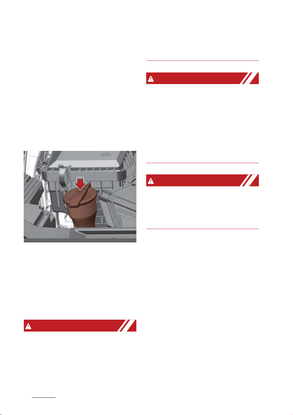
Maintenance
288
Washer fluid
Washer fluid
Washer fluid is used when wiping
the windshield of the vehicle with a
windshield wiper. You should check
and refill washer fluid periodically to
make sure that it doesn't run out.
Checking the washer fluid level
The reservoir is translucent so that
you can check the level with a quick
visual inspection.
䳜 Check the fluid level in the washer
fluid reservoir and add fluid if
necessary. Plain water may be
used if washer fluid is not avail
-
able.
However, use washer solvent with
antifreeze characteristics in cold
climates to prevent freezing.
WARNING
Flammable fluid
Do not allow the washer fluid to
come in contact with open flames or
sparks. The windshield washer fluid
reservoir is flammable under certain
circumstances. This can result in a
fire.
WARNING
Coolant
䳜 Do not use radiator coolant or
antifreeze in the washer fluid res
-
ervoir.
䳜 Radiator coolant can severely
obscure visibility when sprayed on
the windshield and may cause
loss of vehicle control.
WARNING
Windshield fluid
Do not drink the windshield washer
fluid. The windshield washer fluid is
poisonous to humans and animals.
OMQ4H070008
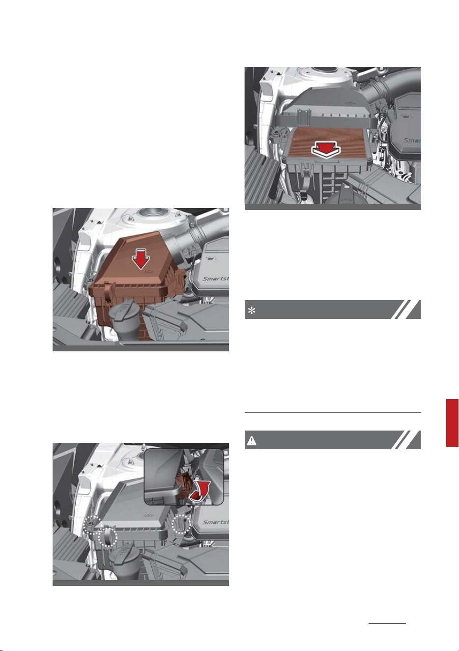
29
8
8
Maintenance Air cleaner filter
Air cleaner filter
A genuine Kia air cleaner filter is
recommended when the filter is
replaced.
Replacing air cleaner filter
Air cleaner filter must be replaced
when necessary, and should not be
washed.
You can clean the filter when
inspecting the air cleaner compart
-
ment. Clean the filter by using com
-
pressed air.
1. Loosen the air cleaner cover
attaching clips and open the cover.
2. Wipe the inside of the air cleaner.
3. Replace the air cleaner filter.
4. Lock the cover with the cover
attaching clips.
Replace the filter according to the
Maintenance Schedule.
NOTICE
If the vehicle is operated in
extremely dusty or sandy areas,
replace the element more often
than the usual recommended inter
-
vals. (Refer to "Severe driving condi
-
tions" on page 8-15.)
CAUTION
Air filter maintenance
䳜 Do not drive with the air cleaner
removed; this will result in exces
-
sive engine wear.
䳜 When removing the air cleaner fil
-
ter, be careful that dust or dirt
does not enter the air intake, or
damage may result.
OMQ4H070009
OMQ4H070010
OMQ4H070011
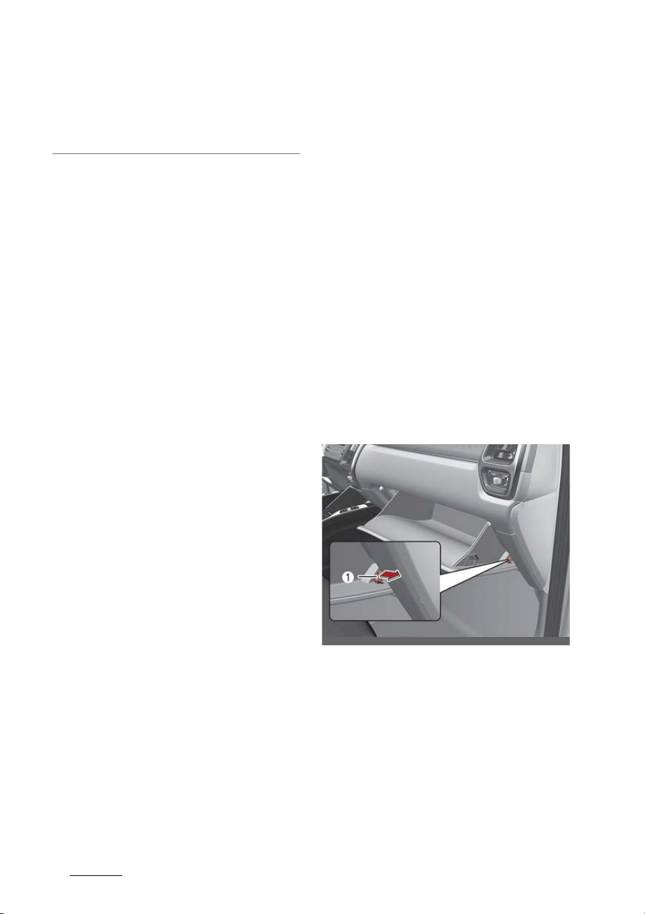
Maintenance
308
Climate control air filter
䳜 Use a Kia genuine part. Use of a
non-genuine part could damage
the air flow sensor.
Climate control air filter
Filter inspection
The climate control air filter should
be replaced according to the main
-
tenance schedule. If the vehicle is
operated in severely air-polluted
cities or on dusty rough roads for a
long period, it should be inspected
more frequently and replaced ear
-
lier. When you replace the climate
control air filter, replace it perform
-
ing the following procedure, and be
careful to avoid damaging other
components.
1. Open the glove box and remove
the stoppers (1) on both sides.
2. With the glove box open, pull the
support strap.
OMQ4070018
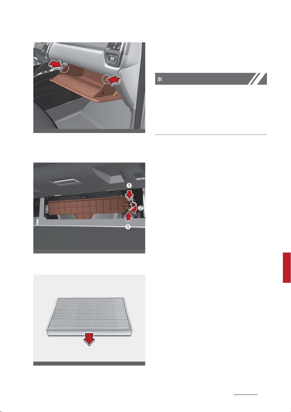
31
8
8
Maintenance Climate control air filter
3. Remove the climate control air fil
-
ter cover by pulling out both sides
of the cover.
4. Replace the climate control air fil
-
ter.
5. Reassemble in the reverse order
of disassembly.
NOTICE
When replacing the climate control
air filter install it properly. Other
-
wise, the system may produce noise
and the effectiveness of the filter
may be reduced.
OMQ4070017
OMQ4070019
ODEEV098011NR
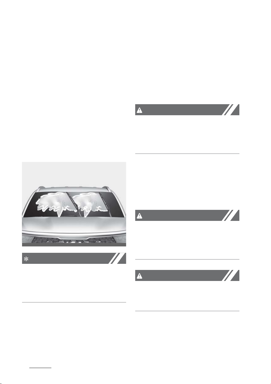
Maintenance
328
Wiper blades
Wiper blades
When the wipers no longer clean
adequately, the blades may be worn
or cracked, and require replacement.
To prevent damage to the wiper
arms or other components, do not
attempt to move the wipers manu
-
ally.
The use of a non-specified wiper
blade could result in wiper malfunc
-
tion and failure.
Blade inspection
NOTICE
Commercial hot waxes applied by
automatic car washes have been
known to make the windshield diffi
-
cult to clean.
Contamination of either the wind
-
shield or the wiper blades with for
-
eign matter can reduce the
effectiveness of the windshield wip
-
ers. Common sources of contamina
-
tion are insects, tree sap, and hot
wax treatments used by some com
-
mercial car washes. If the blades are
not wiping properly, clean both the
window and the blades with a good
cleaner or mild detergent, and rinse
thoroughly with clean water.
CAUTION
To prevent damage to the wiper
blades, do not use gasoline, kero
-
sene, paint thinner, or other sol
-
vents on or near them.
Blade replacement
When the wipers no longer clean
adequately, the blades may be worn
or cracked, and require replacement.
CAUTION
To prevent damage to the wiper
arms or other components, do not
attempt to move the wipers manu
-
ally.
CAUTION
The use of a non-specified wiper
blade could result in wiper malfunc
-
tion and failure.
OMQ4071022
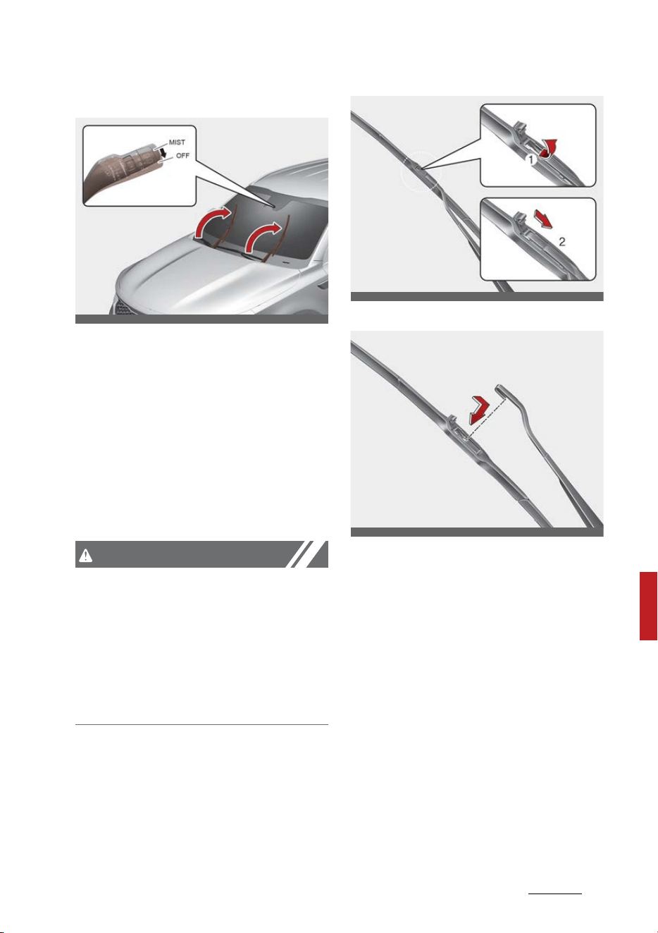
33
8
8
Maintenance Wiper blades
Front windshield wiper blade
For your convenience, move the
windshield wiper blades to the ser
-
vice position as follows;
After turning off the engine, move
the wiper switch to the single wiping
(MIST) position within 20 seconds
and hold the switch more than 2
seconds until the wiper blade is in
the fully up position.
CAUTION
Wiper arms
䳜 Do not allow the wiper arm to fall
against the windshield, since it
may chip or crack the windshield.
䳜 Do not pull the wiper arm for
-
ward, since arm could chip hood
paint.
1. Raise the wiper arm.
2. Lift up the wiper blade clip. Then
pull down the blade assembly and
remove it.
3. Install the new blade assembly.
4. Return the wiper arm on the
windshield.
5. Turn ENGINE START/STOP button
to the ON position and wiper arms
will return to the normal operat
-
ing position.
OMQ4070023L
ODEEV098016NR
ODEEV098017NR
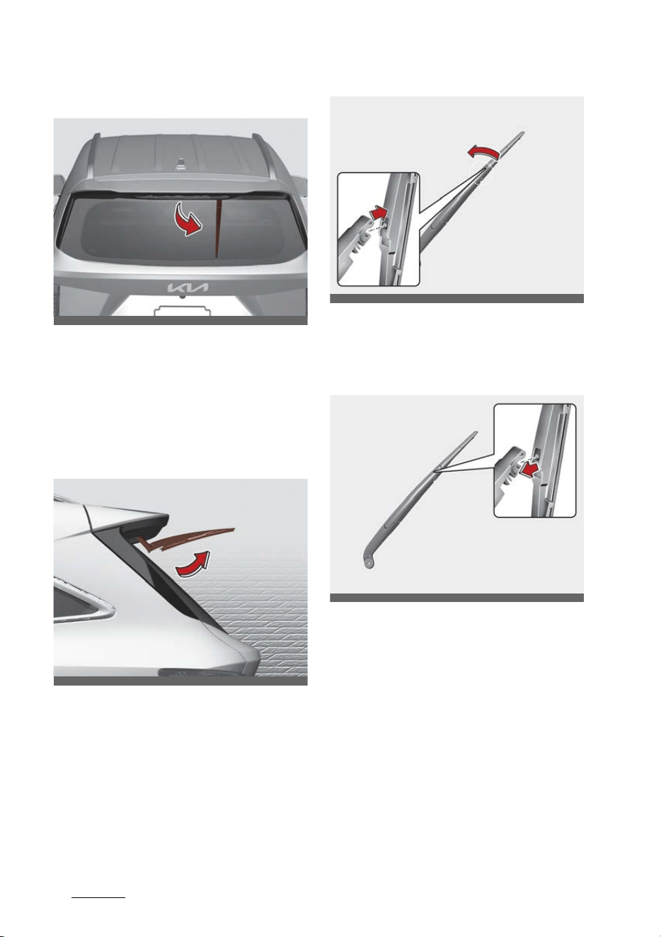
Maintenance
348
Wiper blades
Replacing rear wiper blade
1. Within 20 seconds after the vehi
-
cle is OFF, pull down the wiper
lever to MIST position for over 2
seconds until the wiper moves
down to the bottom middle part.
2. Raise the wiper arm and pull out
the wiper blade assembly.
3. Lift up the wiper blade, and pull
the blade to remove it.
4. Install the new blade assembly by
inserting the center part into the
slot in the wiper arm until it clicks
into place.
5. Make sure the blade assembly is
installed firmly by trying to pull it
slightly.
If the replacement is complete,
put down the wiper arm to place
it on the rear windshield, and turn
the ENGINE START/STOP button
to ON and operate the wipers to
check the blade is installed cor
-
rectly.
To prevent damage to the wiper
arms or other components, have the
OMQ4PH071013
OMQ4070012
OMQ4070104L
OMQ4070094L
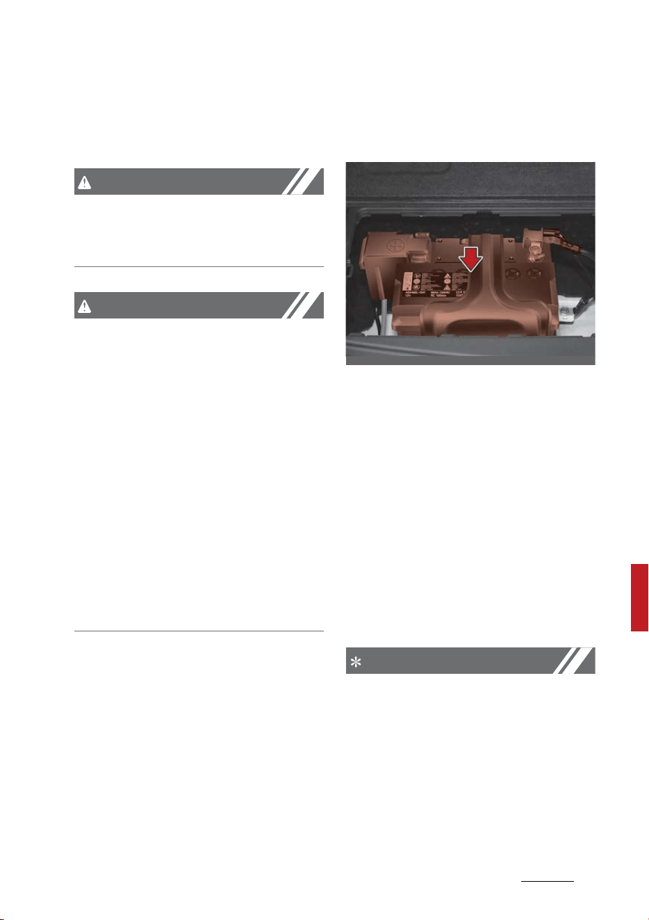
35
8
8
Maintenance Battery
wiper blade replaced by a profes
-
sional workshop. Kia recommends to
visit an authorized Kia dealer.
CAUTION
If the wiper arm receives too much
force while pulling the blade, the
center part may be damaged.
CAUTION
䳜 The wiper could not operate for
approx. 10 seconds when the
wiper is operated without washer
fluid or the blades are frozen. This
is not a malfunction, it is a wiper
protection system activated by
motor overload circuit within the
wiper motor.
䳜 The front windshield should be
cleaned with water hose and
wiped with clean towel with wiper
blades raised up. Also, the wiper
blades should be wiped clean
when the grease or wax is applied
to the blades.
Battery
For best battery service
䳜 Keep the battery securely
mounted.
䳜 Keep the battery top clean and
dry.
䳜 Keep the terminals and connec
-
tions clean, tight, and coated with
petroleum jelly or terminal
grease.
䳜 Rinse any spilled electrolyte from
the battery immediately with a
solution of water and baking soda.
䳜 If the vehicle is not going to be
used for an extended time, dis
-
connect the battery cables.
NOTICE
Your vehicle is equipped with main
-
tenance free battery. If your vehicle
is equipped with the battery marked
with LOWER and UPPER on the side,
you can check the electrolyte level.
The electrolyte level should be
between LOWER and UPPER. If the
electrolyte level is low, it needs to
OMQ4H070028
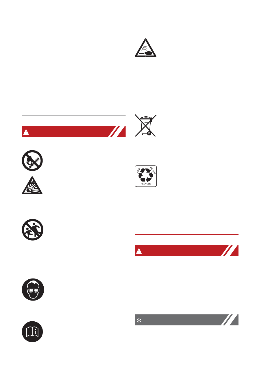
Maintenance
368
Battery
add distilled (demineralized) water
(Never add sulfuric acid or other
electrolyte). When refill, be careful
not to splash the battery and adja
-
cent components. And do not overfill
the battery cells. It can cause corro
-
sion on other parts. Make sure that
the cell caps are tightened.
Contact an authorized Kia dealer.
WARNING
Risk of explosion
Keep lit cigarettes and all
other flames or sparks
away from the battery.
The battery contains
hydrogen -- a highly com
-
bustible gas which will
explode if it comes in contact with a
flame or spark.
Keep batteries out of the
reach of children because
batteries contain highly
corrosive SULFURIC ACID
and electrolytes. Do not allow bat
-
tery acid to contact your skin, eyes,
clothing or paint finish.
Wear eye protection when
charging or working near a
battery. Always provide
ventilation when working
in an enclosed space.
Always read the following
instructions carefully when
handling a battery.
If any electrolyte gets into
your eyes, flush your eyes
with clean water for at
least 15 minutes and get immediate
medical attention. If electrolyte gets
on your skin, thoroughly wash the
contacted area. If you feel pain or
burning sensation, get medical
attention immediately.
An inappropriately dis
-
posed battery can be
harmful to the environ
-
ment and human health.
Dispose the battery according to
your local law(s) or regulation.
The battery contains lead.
Do not dispose of it after
use. Please return the bat
-
tery to an authorized Kia
dealer to be recycled.
Never attempt to recharge the bat
-
tery when the battery cables are
connected.
WARNING
Risk of electrocution
Never touch the electrical ignition
system while the vehicle is running.
This system works with high volt
-
age, which can "zap" you.
NOTICE
If you connect unauthorized elec
-
tronic devices to the battery, the

37
8
8
Maintenance Battery
battery may be discharged. Never
use unauthorized devices.
WARNING
Recharging battery
Never attempt to recharge the bat
-
tery when the battery cables are
connected.
WARNING
Battery lead compound
Battery posts, terminals, and
related accessories contain lead and
lead compounds. Wash hands after
handling.
Battery recharging
Your vehicle has a maintenance-
free, calcium-based battery.
䳜 If the battery becomes discharged
in a short time (because, for
example, the headlamps or inte
-
rior lights were left on while the
vehicle was not in use), recharge it
by slow charging (trickle) for 10
hours.
䳜 If the battery gradually dis
-
charges because of high electric
load while the vehicle is being
used, recharge it at 20~30 A for
two hours.
When recharging the battery,
observe the following precautions:
䳜 The battery must be removed
from the vehicle and placed in an
area with good ventilation.
䳜 Do not allow cigarettes, sparks, or
flame near the battery.
䳜 Watch the battery during
charging, and stop or reduce the
charging rate in following cases:
1. the battery cells begin gassing
(boiling) violently
2. the electrolyte temperature of
any cell exceeds 120 F (49 C).
䳜 Wear eye protection when check
-
ing the battery during charging.
䳜 Before performing maintenance
or recharging the battery, turn
off all accessories and stop the
vehicle.
䳜 Disconnect the battery charger in
the following order.
1. Turn off the battery charger
main switch.
2. Unhook the negative clamp
from the negative battery ter
-
minal.
3. Unhook the positive clamp from
the positive battery terminal.
䳜 The negative battery cable must
be removed first and installed last
when the battery is disconnected.
CAUTION
AGM battery
䳜 Absorbent Glass Mat (AGM) bat
-
teries are maintenance free and
have the AGM battery serviced by
an authorized Kia dealer.

Maintenance
388
Tires and wheels
For charging your AGM battery,
use only fully automatic battery
chargers that are specially devel
-
oped for AGM batteries.
䳜 When replacing the AGM battery,
use parts for replacement from
an authorized Kia dealer.
䳜 Do not open or remove the cap on
top of the battery. This may
cause leaks of internal electrolyte
that could result in severe injury.
Reset items
The following items should be reset
after the battery has been dis
-
charged or the battery has been
disconnected.
䳜 Auto up/down window (Refer to
"Window opening and closing" on
page 5-43)
䳜 Trip computer (Refer to "Trip
information (trip computer)" on
page 5-100)
䳜 Climate control system (Refer to
"Automatic climate control sys
-
tem" on page 5-161)
䳜 Sunroof (Refer to "Panoramic
sunroof (if equipped)" on page 5-
55)
Tires and wheels
For proper maintenance, safety, and
maximum fuel economy, you must
always maintain the recommended
tire inflation pressures and stay
within the load limits and weight
distribution recommended for your
vehicle.
Recommended cold tire inflation
pressures
All tire pressures should be checked
when the tires are cold. "Cold Tires"
means the vehicle has not been
driven for at least three hours or
driven less than 1 mile (1.6 km).
Recommended pressures must be
maintained for the best ride, vehicle
handling, and minimum tire wear.
For recommended inflation pres
-
sure, refer to "Tires and wheels" on
page 8-38.
All specifications (sizes and pres
-
sures) can be found on a label
attached to the driver's side center
pillar.
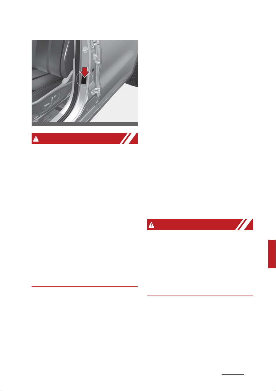
39
8
8
Maintenance Tires and wheels
WARNING
Tire underinflation
Inflate your tires consistent with
the instructions provided in this
manual. Regularly check the tire
inflation pressure, and correct it as
needed; at least twice a month and
before any long trips on the road. If
you fail to observe this precaution,
you may be driving on underinflated
tires, which may not only compro
-
mise your vehicle's driving stability,
but may also lead to tire damage
and the risk of an accident. This risk
is much higher on hot days and
when driving for long periods at high
speeds.
Failure to maintain specified pres
-
sure may result in excessive wear,
poor handling, reduced fuel econ
-
omy, deformation of tire and/or
wheel, harsh ride conditions, possi
-
bility for additional damage from
road hazards, or result in tire failure.
Tire pressure
Always observe the following:
䳜 Check tire pressure when the tires
are cold. (After vehicle has been
parked for at least three hours or
hasn't been driven more than 1
mile (1.6 km) since startup.)
䳜 Check the pressure of your spare
tire each time you check the pres
-
sure of other tires.
䳜 Never overload your vehicle. Be
careful not to overload a vehicle
luggage rack if your vehicle is
equipped with one.
䳜 Warm tires normally exceed rec
-
ommended cold tire pressures by
4~6 psi (28~41 kPa). Do not
release air from warm tires to
adjust the pressure or the tires
will be underinflated.
WARNING
Tire Inflation
Overinflation or underinflation can
reduce tire life, adversely affect
vehicle handling, and lead to sudden
tire failure. This could result in loss
of vehicle control and potential
injury.
Checking tire inflation pressure
Check your tires once a month or
more.
Use a good quality gauge to check
tire pressure. You cannot tell if your
OMQ4AH080004

Maintenance
408
Tires and wheels
tires are properly inflated simply by
looking at them. Radial tires may
look properly inflated even when
they're underinflated.
Check the tire's inflation pressure
when the tires are cold. "Cold"
means your vehicle has been sitting
or at least three hours or driven no
more than 1 mile (1.6 km).
1. Remove the valve cap from the
tire valve stem.
2. Press the tire gauge firmly onto
the valve to get a pressure mea
-
surement. If the cold tire inflation
pressure matches the recom
-
mended pressure on the tire and
loading information label, no fur
-
ther adjustment is necessary.
3. If the pressure is low, add air until
you reach the recommended
amount.
4. If you overfill the tire, release air
by pushing on the metal stem in
the center of the tire valve.
5. Recheck the tire pressure with
the tire gauge.
6. Be sure to put the valve caps back
on the valve stems. They help
prevent leaks by keeping out dirt
and moisture.
Inspect your tires frequently for
proper inflation as well as wear and
damage. Always use a tire pressure
gauge.
Tires with too much or too little
pressure wear unevenly. This could
result in poor handling, loss of vehi
-
cle control, and sudden tire failure
leading to accidents, injuries, and
even death. The recommended cold
tire pressure for your vehicle can be
found in this manual and on the tire
label located on the driver's side
center pillar.
Tire rotation
To equalize tread wear, it is recom
-
mended that the tires be rotated
every 8,000 miles (13,000 km) or
sooner if irregular wear develops.
During rotation, check the tires for
correct balance.
When rotating tires, check for
uneven wear and damage. Abnormal
wear is usually caused by incorrect
tire pressure, improper wheel align
-
ment, out of-balance wheels, severe
braking or severe cornering. Look
for bumps or bulges in the tread or
side of tire. Replace the tire if you
find either of these conditions.
Replace the tire if fabric or cord is
visible. After rotation, be sure to
bring the front and rear tire pres
-
sures to specification and check lug
nut tightness. (proper torque is
79~94 lbfft [11~13 kgfm])
Refer to "Tires and wheels" on page
8-38.
Disc brake pads should be inspected
for wear whenever tires are
rotated.
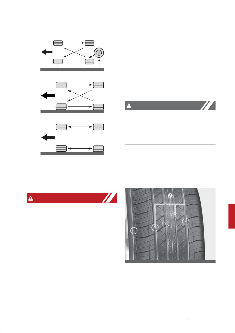
41
8
8
Maintenance Tires and wheels
With a full-size spare tire (if equipped)
Without a spare tire
Directional tires (if equipped)
Rotate radial tires that have an
asymmetric tread pattern only from
front to rear and not from right to
left.
WARNING
Mixing tires
Do not mix bias ply and radial ply
tires under any circumstances. This
may cause unusual handling charac
-
teristics.
Wheel alignment and tire balance
The wheels on your vehicle were
aligned and balanced carefully at the
factory to give you the longest tire
life and best overall performance.
If you notice unusual tire wear or
your vehicle pulling one way or the
other, the alignment may need to be
reset.
If you notice your vehicle vibrating
when driving on a smooth road,
your wheels may need to be rebal
-
anced.
CAUTION
Wheel weight
Improper wheel weights can dam
-
age your vehicle's aluminum wheels.
Use only approved wheel weights.
Tire replacement
If the tire is worn evenly, a tread
wear indicator will appear as a solid
band across the tread.
[A] : Tread wear indicator
This shows there is less than 1/16 in
(1.6 mm) of tread left on the tire.
Replace the tire when this happens.
CBGQ0706
ODEEV098029NR
CBGQ0707A
OMQ4070103L

Maintenance
428
Tires and wheels
Do not wait for the band to appear
across the entire tread before
replacing the tire.
The Anti-lock Brake System (ABS)
works by comparing the speed of
the wheels. The tire size affects
wheel speed. When replacing tires,
all 4 tires must use the same size
originally supplied with the vehicle.
Using tires of a different size can
cause the ABS and Electronic Stabil
-
ity Control (ESC) to work irregularly.
It is best to replace all four tires at
the same time. If that is not possi
-
ble, or necessary, then replace the
two front or two rear tires as a pair.
Replacing just one tire can seriously
affect your vehicle's handling.
NOTICE
We recommend that when replac
-
ing tires, use the same originally
supplied with the vehicles. If not,
that affects driving performance.
Wheel replacement
When replacing the metal wheels
for any reason, make sure the new
wheels are equivalent to the original
factory units in diameter, rim width
and offset.
A wheel with an incorrect size may
adversely affect many things: wheel
and bearing life, braking and stop
-
ping abilities, handling characteris
-
tics, ground clearance, body-to-tire
clearance, snow chain clearance,
speedometer and odometer calibra
-
tion, headlamp aiming and bumper
height.
CAUTION
Wheels
Wheels that do not meet Kia specifi
-
cations may fit poorly and result in
damage to the vehicle or unusual
handling and poor vehicle control.
Tire traction
Tire traction can be reduced if you
drive on worn tires, tires that are
improperly inflated or on slippery
road surfaces.
Tires should be replaced when tread
wear indicators appear. Slow down
whenever there is rain, snow or ice
on the road to reduce the possibility
of losing control of the vehicle.
Tire maintenance
In addition to proper inflation, cor
-
rect wheel alignment helps to
decrease tire wear.
If you find a tire is worn unevenly,
have your dealer check the wheel
alignment.
Make sure the newly installed tires
are balanced correctly to increase
vehicle ride comfort and tire life. In
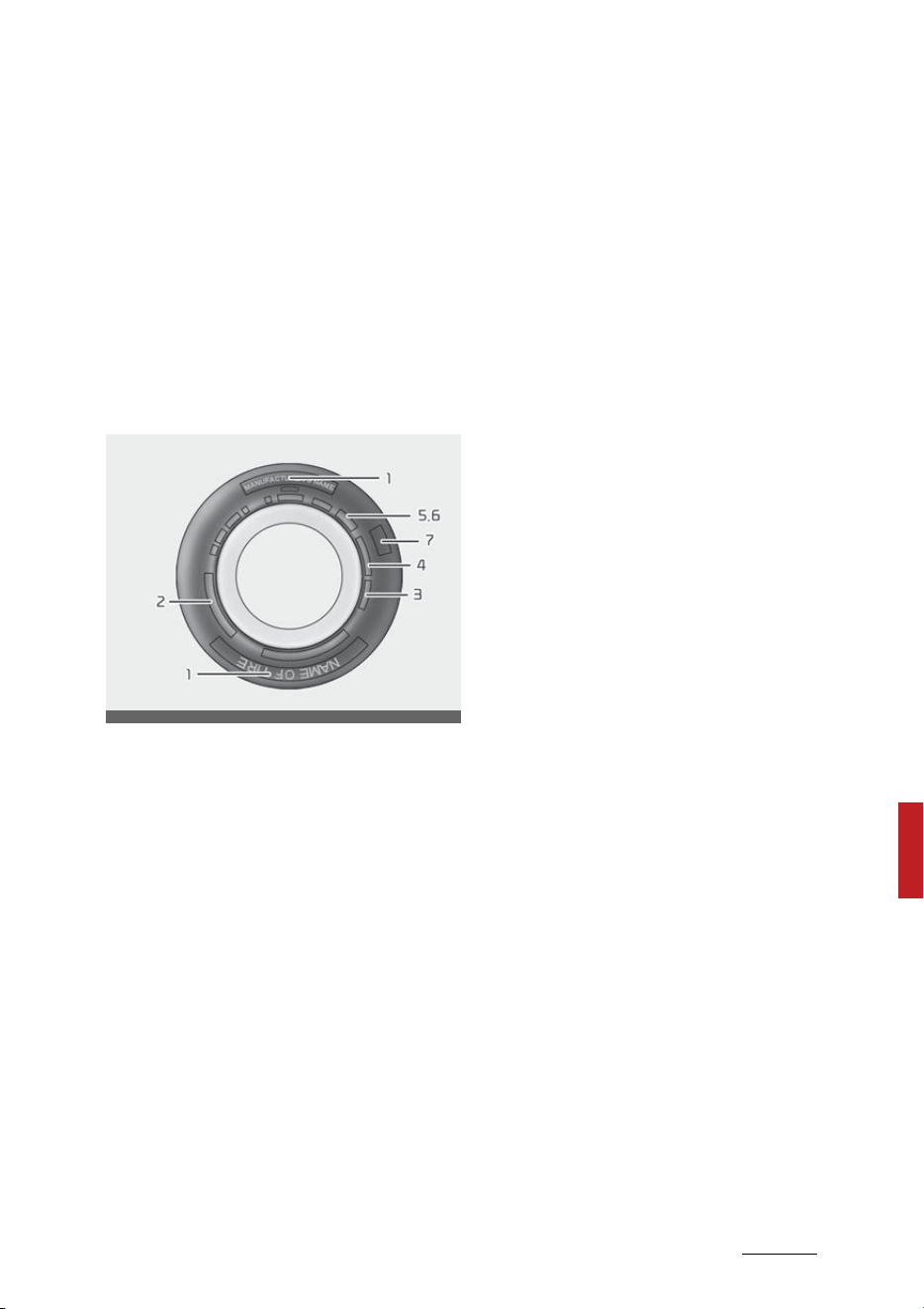
43
8
8
Maintenance Tires and wheels
addition, always rebalance the tire
when the tire is removed from the
wheel.
Tire sidewall labeling
This information identifies and
describes the fundamental charac
-
teristics of the tire and also provides
the Tire Identification Number (TIN)
for safety standard certification.
The TIN can be used to identify the
tire in case of a recall.
1. Manufacturer or brand name
Manufacturer or Brand name is
shown.
2. Tire size designation
A tire's sidewall is marked with a tire
size designation. You will need this
information when selecting replace
-
ment tires for your vehicle. The fol
-
lowing explains what the letters and
numbers in the tire size designation
mean.
Example tire size designation:
(These numbers are provided as an
example only; your tire size desig
-
nator could vary depending on your
vehicle.)
P235/55R19 101H
䳜 P: Applicable vehicle type (tires
marked with the prefix "P" are
intended for use on passenger
vehicles or light trucks; however,
not all tires have this marking).
䳜 235: Tire width in millimeters.
䳜 55: Aspect ratio. The tire's section
height as a percentage of its
width.
䳜 R: Tire construction code (Radial).
䳜 19: Rim diameter in inches.
䳜 101: Load Index, a numerical code
associated with the maximum
load the tire can carry.
䳜 H: Speed Rating Symbol. See the
speed rating chart in this section
for additional information.
Wheel size designation
Wheels are also marked with
important information that you
need if you ever have to replace one.
The following explains what the let
-
ters and numbers in the wheel size
designation mean.
Example wheel size designation:
7.5JX19
䳜 7.5: Rim width in inches.
䳜 J: Rim contour designation.
䳜 19: Rim diameter in inches.
ODEEV098031NR

Maintenance
448
Tires and wheels
Tire speed ratings
The chart below lists many of the
different speed ratings currently
being used for passenger vehicle
tires. The speed rating is part of the
tire size designation on the sidewall
of the tire. This symbol corresponds
to that tire's designed maximum
safe operating speed.
3. Checking tire life
Any tires that are over 6 years old,
based on the manufacturing date,
should be replaced by new ones. You
can find the manufacturing date on
the tire sidewall (possibly on the
inside of the wheel), displaying the
DOT code. The DOT code is a series
of numbers on a tire consisting of
numbers and English letters. The
manufacturing date is designated
by the last four digits (characters)
of the DOT code.
DOT: XXXX XXXX OOOO
The front part of the DOT means a
plant code number, tire size and
tread pattern and the last four
numbers indicate week and year
manufactured.
For example:
DOT XXXX XXXX 1621 represents
that the tire was produced in the
16th week of 2021.
WARNING
Tire age
Replace tires within the recom
-
mended time frame. Failure to
replace tires as recommended can
result in sudden tire failure, which
could lead to a loss of control and an
accident.
4. Tire ply composition and mate
-
rial
The number of layers or plies of
rubber- coated fabric in the tire.
Tire manufacturers also must indi
-
cate the materials in the tire, which
include steel, nylon, polyester, and
others. The letter "R" means radial
ply construction; the letter "D"
means diagonal or bias ply con
-
struction; and the letter "B" means
belted-bias ply construction.
5. Maximum permissible inflation
pressure
This number is the greatest amount
of air pressure that should be put in
the tire. Do not exceed the maxi
-
mum permissible inflation pressure.
Speed Rating
Symbol
Maximum Speed
S 112 mph (180 km/h)
T 118 mph (190 km/h)
H 130 mph (210 km/h)
V 149 mph (240 km/h)
W 168 mph (270 km/h)
Y 186 mph (300 km/h)

45
8
8
Maintenance Tires and wheels
Refer to "Certification label" on page
6-236 for recommended inflation
pressure.
6. Maximum load rating
This number indicates the maximum
load in kilograms and pounds that
can be carried by the tire. When
replacing the tires on the vehicle,
always use a tire that has the same
load rating as the factory installed
tire.
7. Uniform tire quality grading
UNIFORM TIRE QUALITY GRADING
Quality grades can be found where
applicable on the tire sidewall
between tread shoulder and maxi
-
mum section width.
For example:
䳜 Treadwear 200
䳜 Traction AA
䳜 Temperature A
Tires degrade over time, even when
they are not being used. Regardless
of the remaining tread, we recom
-
mend that tires be replaced after
approximately six (6) years of nor
-
mal service. Heat caused by hot cli
-
mate or frequent high loading
conditions can accelerate the aging
process.
Tread wear
The tread wear grade is a compara
-
tive rating based on the wear rate
of the tire when tested under con
-
trolled conditions on a specified
government test course. For exam
-
ple, a tire graded 150 would wear
one-and-a-half times (1) as well
on the government course as a tire
graded 100.
The relative performance of tires
depends upon the actual conditions
of their use. Performance may
depart significantly from the norm
due to variations in driving habits,
service practices and differences in
road characteristics and climate.
These grades are molded on the
side-walls of passenger vehicle
tires. The tires available as standard
or optional equipment on your vehi
-
cle may vary with respect to grade.
Traction - AA, A, B & C
The traction grades, from highest to
lowest, are AA, A, B and C. Those
grades represent the tire's ability to
stop on wet pavement as measured
under controlled conditions on spec
-
ified government test surfaces of
asphalt and concrete. A tire marked
C may have poor traction perfor
-
mance.
The traction grade assigned to this
tire is based on straight-ahead
braking traction tests, and does not
include acceleration, cornering,
hydroplaning, or peak traction char
-
acteristics.
Temperature -A, B & C
The temperature grades are A (the
highest), B and C representing the
tire's resistance to the generation of

Maintenance
468
Tires and wheels
heat and its ability to dissipate heat
when tested under controlled condi
-
tions on a specified indoor labora
-
tory test wheel.
Sustained high temperature can
cause the material of the tire to
degenerate and reduce tire life, and
excessive temperature can lead to
sudden tire failure. The grade C cor
-
responds to a level of performance
which all passenger vehicle tires
must meet under the Federal Motor
Vehicle Safety Standard No. 109.
Grades B and A represent higher
levels of performance on the labo
-
ratory test wheel than the mini
-
mum required by law.
Tire terminology and definitions
Refer to the following for detailed
definitions of the terms that are
found in the tire description.
Air Pressure The amount of air
inside the tire pressing outward on
the tire. Air pressure is expressed in
pounds per square inch (psi) or kilo
-
pascal (kPa).
Accessory Weight The combined
weight of optional accessories.
Some examples of optional accesso
-
ries are automatic transmission,
power seats, and air conditioning.
Aspect Ratio The relationship of a
tire's height to its width.
Belt A rubber coated layer of cords
that is located between the plies
and the tread. Cords may be made
from steel or other reinforcing
materials.
Bead The tire bead contains steel
wires wrapped by steel cords that
hold the tire onto the rim.
Bias Ply Tire A pneumatic tire in
which the plies are laid at alternate
angles less than 90 degrees to the
centerline of the tread.
Cold Tire Pressure The amount of
air pressure in a tire, measured in
pounds per square inch (psi) or kilo
-
pascals (kPa) before a tire has built
up heat from driving.
Curb Weight The weight of a motor
vehicle with standard and optional
equipment (including the maximum
capacity of fuel, oil and coolant), but
without passengers and cargo.
DOT Markings A code molded into
the sidewall of a tire signifying that
the tire is in compliance with the
U.S. Department of Transportation
motor vehicle safety standards. The
DOT code includes the Tire Identifi
-
cation Number (TIN), an alphanu
-
meric designator which can also
identify the tire manufacturer, pro
-
duction plant, brand and date of
production.
GVWR Gross Vehicle Weight Rating
GAWR FRT Gross Axle Weight Rating
for the Front axle.

47
8
8
Maintenance Tires and wheels
GAWR RR Gross Axle Weight Rating
for the Rear axle.
Intended Outboard Sidewall The side
of an asymmetrical tire that must
always face outward when mounted
on a vehicle.
Kilopascal (kPa) The metric unit for
air pressure.
Light truck (LT) tire A tire desig
-
nated by its manufacturer as pri
-
marily intended for use on
lightweight trucks or multipurpose
passenger vehicles.
Load ratings The maximum load
that a tire is rated to carry for a
given inflation pressure.
Load Index An assigned number
ranging from 1 to 279 that corre
-
sponds to the load carrying capacity
of a tire.
Maximum Inflation Pressure The
maximum air pressure to which a
cold tire may be inflated. The maxi
-
mum air pressure is molded onto
the sidewall.
Maximum Load Rating The load rat
-
ing for a tire at the maximum per
-
missible inflation pressure for that
tire.
Maximum Loaded Vehicle Weight
The sum of curb weight; accessory
weight; vehicle capacity weight; and
production options weight.
Normal Occupant Weight The num
-
ber of occupants a vehicle is
designed to seat multiplied by 150
lbs. (68 kg).
Occupant Distribution Designated
seating positions.
Outward Facing Sidewall The side of
a asymmetrical tire that has a par
-
ticular side that faces outward
when mounted on a vehicle. The
outward facing sidewall bears white
lettering or bears manufacturer,
brand, and/or model name molding
that is higher or deeper than the
same moldings on the inner facing
sidewall.
Passenger (P-Metric) Tire A tire
used on passenger cars and some
light duty trucks and multipurpose
vehicles.
Ply A layer of rubber-coated parallel
cords.
Pneumatic tire A mechanical device
made of rubber, chemicals, fabric
and steel or other materials, that,
when mounted on an automotive
wheel, provides the traction and
contains the gas or fluid that sus
-
tains the load.
Production options weight The
combined weight of installed regular
production options weighing over 5
lbs. (2.3 kg) in excess of the stan
-
dard items which they replace, not
previously considered in curb weight

Maintenance
488
Tires and wheels
or accessory weight. Examples
include heavy duty brakes, ride lev
-
elers, roof rack, heavy duty battery,
and special trim.
Recommended Inflation Pressure
Vehicle manufacturer's recom
-
mended tire inflation pressure and
shown on the tire placard.
Radial Ply Tire A pneumatic tire in
which the ply cords that extend to
the beads are laid at 90 degrees to
the centerline of the tread.
Rim A metal support for a tire and
upon which the tire beads are
seated.
Sidewall The portion of a tire
between the tread and the bead.
Speed Rating An alphanumeric code
assigned to a tire indicating the
maximum speed at which a tire can
operate.
Traction The friction between the
tire and the road surface. The
amount of grip provided.
Tread The portion of a tire that
comes into contact with the road.
Treadwear Indicators Narrow bands,
sometimes called "wear bars," that
show across the tread of a tire
when only 2/32 inch (1.6 mm) of
tread remains.
UTQGS Uniform Tire Quality Grading
Standards, a tire information sys
-
tem that provides consumers with
ratings for a tire's traction, tem
-
perature and treadwear. Ratings are
determined by tire manufacturers
using government testing proce
-
dures. The ratings are molded into
the sidewall of the tire.
Vehicle Capacity Weight The weight
of designated seating positions
multiplied by 150 lbs. (68 kg) plus
the rated cargo and luggage load.
Vehicle Maximum Load on the Tire
Load on an individual tire due to curb
and accessory weight plus maxi
-
mum occupant and cargo weight.
Vehicle Normal Load on the Tire
Load on an individual tire that is
determined by distributing to each
axle its share of the curb weight,
accessory weight, and normal occu
-
pant weight and driving by 2.
Vehicle Placard A label permanently
attached to a vehicle showing the
original equipment tire size and rec
-
ommended inflation pressure.
All season tires
Kia specifies all season tires on
some models to provide good per
-
formance for use all year round,
including snowy and icy road condi
-
tions.
All season tires are identified by ALL
SEASON and/or M+S (Mud and
Snow) on the tire sidewall. Snow
tires have better snow traction than

49
8
8
Maintenance Tires and wheels
all season tires and may be more
appropriate in some areas.
Summer tires
Kia specifies summer tires on some
models to provide superior perfor
-
mance on dry roads.
Summer tire performance is sub
-
stantially reduced in snow and ice.
Summer tires do not have the tire
traction rating M+S (Mud and Snow)
on the tire side wall. if you plan to
operate your vehicle in snowy or icy
conditions, Kia recommends the use
of snow tires or all season tires on
all four wheels.
Snow tires
If you equip your vehicle with snow
tires, they should be the same size
and have the same load capacity as
the original tires.
Snow tires should be installed on all
four wheels; otherwise, poor han
-
dling may result.
Snow tires should carry 4 psi (28
kPa) more air pressure than the
pressure recommended for the
standard tires on the tire label on
the driver's side of the center pillar,
or up to the maximum pressure
shown on the tire sidewall, which
-
ever is less.
Do not drive faster than 75 mph
(120 km/h) when your vehicle is
equipped with snow tires.
WARNING
Do not use summer tires at tem
-
peratures below 45 F (7 C) or
when driving on snow or ice. At
temperatures below 45 F (7 C),
summer tires can lose elasticity, and
therefore traction and braking
power as well. Change the tires on
your vehicle to winter or all-
weather tires of the same size as
the standard tires of the vehicle.
Both types of tires are identified by
the M+S (Mud and Snow) marking.
Using summer tires at very cold
temperatures could cause cracks to
form, thereby damaging the tires
permanently.
Tire chains
Tire chains, if necessary, should be
installed on the front wheels.
Be sure that the chains are installed
in accordance with the manufac
-
turer's instructions.
To minimize tire and chain wear, do
not continue to use tire chains when
they are no longer needed.
䳜 When driving on roads covered
with snow or ice, drive at speeds
less than 20 mph (30 km/h).

Maintenance
508
Tires and wheels
䳜 Use the SAE "S" class or wire
chains.
䳜 If you hear noise caused by chains
contacting the body, retighten the
chain to avoid contact with the
vehicle body.
䳜 To prevent body damage,
retighten the chains after driving
0.3~0.6 miles (0.5~1.0 km).
䳜 Do not use tire chains on vehicles
equipped with aluminum wheels.
In unavoidable circumstance, use
a wire type chain.
䳜 Use wire chains less than 0.47
inches (12 mm) to prevent dam
-
age to the chain's connection.
Radial-ply tires
Radial-ply tires provide improved
tread life, road hazard resistance
and smoother high speed ride.
The radial-ply tires used on this
vehicle are of belted construction,
and are selected to complement the
ride and handling characteristics of
your vehicle. Radial-ply tires have
the same load carrying capacity, as
bias-ply or bias belted tires of the
same size, and use the same rec
-
ommended inflation pressure.
Mixing of radial-ply tires with bias-
ply or bias belted tires is not recom
-
mended. Any combinations of
radial-ply and bias-ply or bias
belted tires when used on the same
vehicle will seriously deteriorate
vehicle handling. The best rule to
follow is: Identical radial-ply tires
should always be used as a set of
four.
Longer wearing tires can be more
susceptible to irregul ar tread wear.
It is very important to follow the tire
rotation interval shown in this sec
-
tion to achieve the tread life poten
-
tial of these tires. Cuts and
punctures in radial-ply tires are
repairable only in the tread area,
because of sidewall flexing. Consult
your tire dealer for radial-ply tire
repairs.
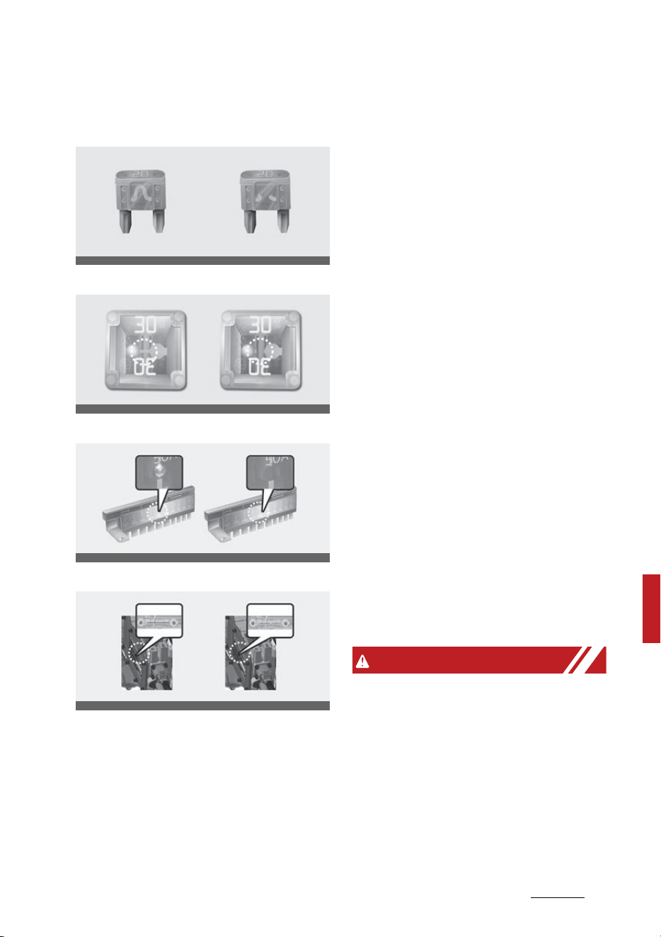
51
8
8
Maintenance Fuses
Fuses
Blade type
Cartridge type
Multi fuse
High voltage fuse
* Left side: Normal, Right side:
Blown
* The actual fuse/relay panel label
may differ from equipped items.
A vehicle's electrical system is pro
-
tected from electrical overload
damage by fuses.
This vehicle has 2 (or 3) fuse panels,
one located in the driver's side panel
bolster, the other in the engine
compartment near the battery.
If any of your vehicle's lights, acces
-
sories, or controls do not work,
check the appropriate circuit fuse. If
a fuse has blown, the element inside
the fuse will melt.
If the electrical system does not
work, first check the driver's side
fuse panel.
If the replacement fuse blows, this
indicates an electrical problem.
Avoid using the system involved and
immediately consult an authorized
Kia dealer.
Three kinds of fuses are used: blade
type for lower amperage rating,
cartridge type, and multi fuse for
higher amperage ratings.
WARNING
Fuse replacement
䳜 Never replace a fuse with any
-
thing but another fuse of the
same rating.
䳜 A higher capacity fuse could cause
damage and possibly a fire.
䳜 Never install a wire or aluminum
foil instead of the proper fuse -
even as a temporary repair. It
ODEEV098032NR
ODEEV098077NR
ODEEV098078NR
OMQ4070071L

Maintenance
528
Fuses
may cause extensive wiring dam
-
age and a possible fire.
䳜 Do not arbitrarily modify or add-
on electric wiring to the vehicle.
CAUTION
Do not use a screwdriver or any
other metal object to remove fuses
because it may cause a short circuit
and damage the system.
NOTICE
䳜 When replacing a fuse, turn the
ENGINE START/STOP button 'OFF'
and turn off switches of all elec
-
trical devices then remove bat
-
tery (-) terminal.
䳜 The actual fuse/relay panel label
may differ from equipped items.
WARNING
Electrical fire
Always ensure replacements fuses
and relays are securely fastened
when installed. Failure to do so can
result in a vehicle fire.
Do not remove fuses, relays and
terminals fastened with bolts or
nuts. The fuses, relays and termi
-
nals may be fastened incompletely,
and it may cause a possible fire. If
fuses, relays and terminals fastened
with bolts or nuts are blown, consult
with an authorized Kia dealer.
CAUTION
When replacing a blown fuse or
relay, make sure the new fuse or
relay fits tightly into the clips. Fail
-
ure to tightly install the fuse or
relay may cause damage to the wir
-
ing and electric systems.
CAUTION
䳜 Do not input any other objects
except fuses or relays into fuse/
relay terminals such as a screw
-
driver or wiring. It may cause con
-
tact failure and system
malfunction.
䳜 Do not plug in screwdrivers or
aftermarket wiring into the ter
-
minal originally designed for fuse
and relays only. The electrical
system and wiring of the vehicle
interior may be damaged or
burned due to contact failure.
䳜 If you directly connect the wire on
the taillamp or replace the bulb
which is over the regulated capac
-
ity to install trailers etc., the inner
junction block can get burned.
WARNING
Electrical wiring repairs
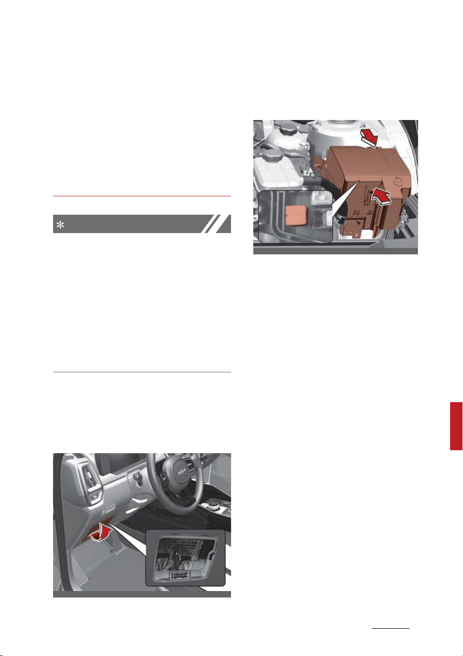
53
8
8
Maintenance Fuses
All electrical repairs should be per
-
formed by authorized Kia dealer
-
ships using approved Kia parts.
Using other wiring components,
especially when retrofitting multi
-
media or theft alarm system, car
phone or radio may cause vehicle
damage and increase the risk of a
vehicle fire.
NOTICE
Remodeling prohibited
Do not rewire your vehicle in any
way as doing so may affect the per
-
formance of several safety features
in your vehicle. Rewiring your vehicle
may also void your warranty and
cause you to be responsible for any
subsequent vehicle damage which
may result.
Inner panel fuse replacement
1. Turn the engine and all other
switches off.
2. Open the fuse panel cover.
3. Pull the suspected fuse straight
out. Use the removal tool pro
-
vided in the main fuse box in the
engine compartment.
4. Check the removed fuse; replace it
if it is blown.
Spare fuses are provided in the
instrument panel fuse panel (or in
the engine compartment fuse
panel).
5. Push in a new fuse of the same
rating, and make sure it fits
tightly in the clips.
If it fits loosely, consult a profes
-
sional workshop. Kia recommends to
consult an authorized Kia dealer.
If you do not have a spare, use a
fuse of the same rating from a cir
-
cuit you may not need for operating
the vehicle, such as the cigarette
lighter fuse.
If the headlamps or taillamps, stop
-
lights, courtesy lamp, day time run
-
ning lights (DRL) do not work and
the fuses are OK, consult an autho
-
rized Kia dealer.
OMQ4H071013
OMQ4PH070031L
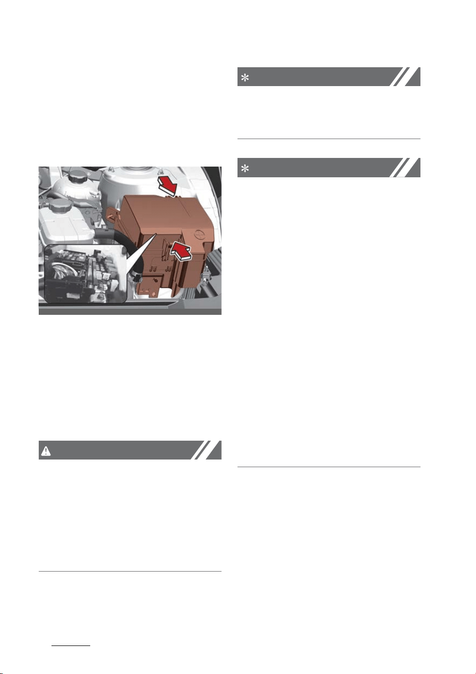
Maintenance
548
Fuses
Engine compartment fuse replace
-
ment
1. Turn the ENGINE START/STOP
button and all other switches OFF.
2. Remove the fuse panel cover by
pressing the tab and pulling the
cover up.
3. Check the removed fuse; replace it
if it is blown. To remove or insert
the fuse, use the fuse puller in the
engine compartment fuse panel.
4. Push in a new fuse of the same
rating, and make sure it fits
tightly in the clips. If it fits loosely,
consult an authorized Kia dealer.
CAUTION
Always securely install the fuse
panel cover in the engine compart
-
ment to protect against electrical
failure which may occur from water
contact. Listen for the audible click
-
ing sound to ensure fuse panel cover
is securely fastened.
NOTICE
If the main (multi) fuse is blown,
have the vehicle checked by an
authorized Kia dealer.
NOTICE
The electronic system may not
function correctly even when the
engine compartment and internal
fuse box's individual fuses are not
disconnected. In such cases, the
cause of the problem may be dis
-
connection of the main fuse (BFT
type), which is located inside the
positive battery terminal (+) cap.
Since the main fuse is designed
more intricately than other parts,
have the vehicle checked by an
authorized Kia dealer.
After checking the fuse panel in the
engine compartment, securely
install the fuse panel cover through
the audible clicking sound. If not,
electrical failures may occur from
water contact.
OMQ4H070014
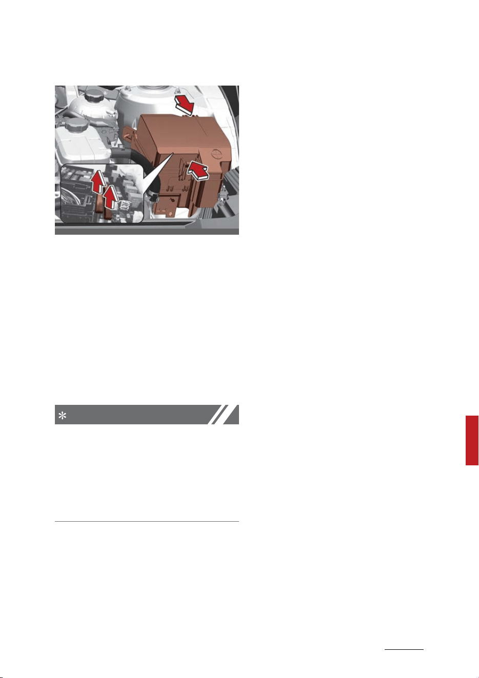
55
8
8
Maintenance Fuses
Main fuse (Multi fuse)
If the main fuse is blown, it must be
removed as follows:
1. Turn off the engine.
2. Disconnect the negative battery
cable.
3. Remove the nuts shown in the
picture above.
4. Replace the fuse with a new one
of the same rating.
5. Reinstall in the reverse order of
removal.
NOTICE
Do not disassemble nor assemble
the multi fuse when it is secured
with nuts and bolts. Incorrect or
partial assembly torque may cause
a fire. Have the vehicle checked by
an authorized Kia dealer.
Fuse/relay panel description
Inside the fuse/relay panel covers,
you can find the fuse/relay label
describing fuse/relay name and
capacity.
OMQ4H070016
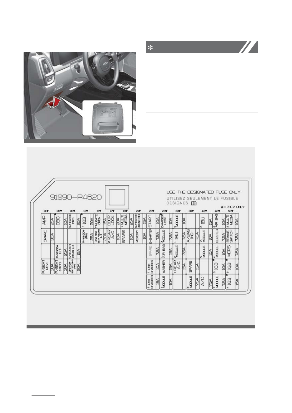
Maintenance
568
Fuses
Driver's side fuse panel
NOTICE
Not all fuse panel descriptions in this
manual may be applicable to your
vehicle. It is accurate at the time of
printing. When you inspect the fuse
panel in your vehicle, refer to the
fuse panel label.
OMQ4071083L
OMQ4071001N

57
8
8
Maintenance Fuses
ICU Junction Block
Fuse Name Fuse rating Circuit Protected
AMP 25A AMP (Amplifier)
P/SEAT (DRV) 30A
Driver Power Seat Switch, IMS (Integrated memory sys
-
tem) Control Module, Driver Lumbar Support Switch
OBC 10 A OBC Unit
P/WINDOW (LH) 25A
Driver Safety Power Window Module, Rear Power Window
Switch Left Handle side/Rear Safety Power Window Mod
-
ule Left Handle side
P/SEAT (PASS) 30A Passenger Power Seat Switch, Passenger Relay Unit
S/HEATER (FRT) 20A
1st Air Ventilation Seat Control Module, 1st Seat Warmer
Control Module
S/HEATER (REAR LH) 15A 2nd Seat Warmer Left Handle side Control Module
2nd ROW SEAT FOLDING
(RH)
20A 2nd Seat Right Handle side Folding Actuator
IG3 1 20A ICM relay box (IG3 Relay)
P/WINDOW (RH) 25A
Passenger Safety Power Window Module, Passenger
Power Window Switch, Rear Power Window Switch Right
Handle side/Rear Safety Power Window Module Right
Handle side
TAILGATE OPEN 15A Tailgate Relay
2nd ROW SEAT FOLDING
(LH)
20A 2nd Seat Warmer Left Handle side Folding Actuator
DOOR LOCK 20A
Door Lock/Unlock Relay, Two Turn Unlock Relay, Data Link
Connector, ICM Relay box (Fuel Lid Lock/Unlock Relay)
REAR A/C 2 10A Rear Air Conditioner Control Module
MULTI MEDIA 1 25A
Audio, Audio/Video & Navigation Head Unit, Fuse - MULTI
MEDIA2
S/HEATER (REAR RH) 15A 2nd Seat Warmer Right Handle side Control Module
MEMORY 10A
Power Tail Gate Unit, IMS (Integrated memory system)
Control Module, Rear Air Conditioner Control Module, ROA
(Rear Occupant Alert), Driver/Passenger Power Outside
Mirror, Instrument Cluster, Front Air Conditioner Control
Module, Front Air Conditioner Control Panel, Head-Up Dis
-
play
START 10A Ignition Switch
E-SHIFTER 7.5A Electronic Shift Dial
USB CHARGER 1 10A
Luggage USB Charge Connector Left Handle side/Right
Handle side
USB CHARGER 2 15A
Rear Console USB Charge Connector Right Handle side,
Driver/Passenger Seat USB Charge Connector

Maintenance
588
Fuses
MODULE 3 7.5A
IBU (Integrated Body Control Unit), ADAS Unit, Front Cam
-
era, Crash Pad Switch, Surround View Monitor Unit, Rear
Corner Radar Unit Left Handle side/Right Handle side,
AWD, ECU, Front Radar Unit, VESS (Virtual Engine Sound
System) Unit, Front Console Switch, Front Seat Ventilation
Switch Left Handle side/Right Handle side
AIR BAG 1 15A
SRS (Supplemental Restraint System) Control Module,
Passenger Occupant Detection Sensor
WASHER 15A Multifunction Switch
MODULE 1 10A
AMP (Amplifier), Rear Seat Entertainment Left Handle
side/Right Handle side, Audio, Audio/Video & Navigation
Head Unit, IBU (Integrated Body Control Unit), Front USB
Charge Connector Left Handle side/Right Handle side,
ADAS Unit, Surround View Monitor Unit
MODULE 9 10A
Driver/Passenger Mood Lamp, ADAS Unit, Data Link Con
-
nector, Surround View Monitor Unit, Driver Door Area Unit,
Key Solenoid, Rain Sensor, Crash Pad Switch, Driver/Pas
-
senger Smart Key Outside Handle, Mood Lamp Unit,
Driver/Passenger Door Mood Lamp Unit, Electronic Refrig
-
erant Reduced Pressure Valve
IBU 1 7.5A
IBU (Integrated Body Control Unit), E/R Junction Block
(Battery C/Fan Relay)
MODULE 2 7.5A Driver Door Area Unit, Overhead Console
REAR A/C 1 15A
Rear Air Conditioner Blower Motor, ICU Junction Block
(Fuse - REAR A/C2)
A/BAG IND 7.5A Instrument Cluster, Overhead Console
MODULE 8 7.5A
ADAS Unit, 1st Air Ventilation Seat Control Module/1st Seat
Warmer Control Module, 2nd Seat Warmer Left Handle
side/Right Handle side Control Module, Rear Air Conditioner
Control Module, AC Inverter, Rear Console AC Inverter Out
-
let
IBU 2 15A IBU (Integrated Body Control Unit)
MODULE10 10A Stop Lamp Switch
MODULE 5 10A
Overhead Console, AMP (Amplifier), Front Wireless Charger
Unit
A/C 7.5A
Front Air Conditioner Control Panel, Front Air Conditioner
Control Module, E/R Junction Block (Blower Relay, PTC
Heater 1/2 Relay)
AIR BAG 2 10A SRS (Supplemental Restraint System) Control Module
CLUSTER 7.5A Instrument Cluster, Head-Up Display
Fuse Name Fuse rating Circuit Protected

59
8
8
Maintenance Fuses
MODULE 4 10A
Audio, Audio/Video & Navigation Head Unit, Data Link Con
-
nector, Crash Pad Switch, Electro Chromic Mirror, IMS
(Integrated memory system) Control Module, 1st Air Ven
-
tilation Seat Control Module/1st Seat Warmer Control
Module, 2nd Seat Warmer Left Handle side/Right Handle
side Control Module
MODULE 7 7.5A IBU (Integrated Body Control Unit)
MULTI MEDIA 2 10A
Rear Seat Entertainment Left Handle side/Right Handle
side
BRAKE SWITCH 7.5A Stop Lamp Switch, IBU (Integrated Body Control Unit)
MDPS 7.5A
MDPS (Motor Driven Power Steering) Unit
* MDPS (Motor Driven Power Steering) is same as EPS
(Electric Power Steering).
Fuse Name Fuse rating Circuit Protected
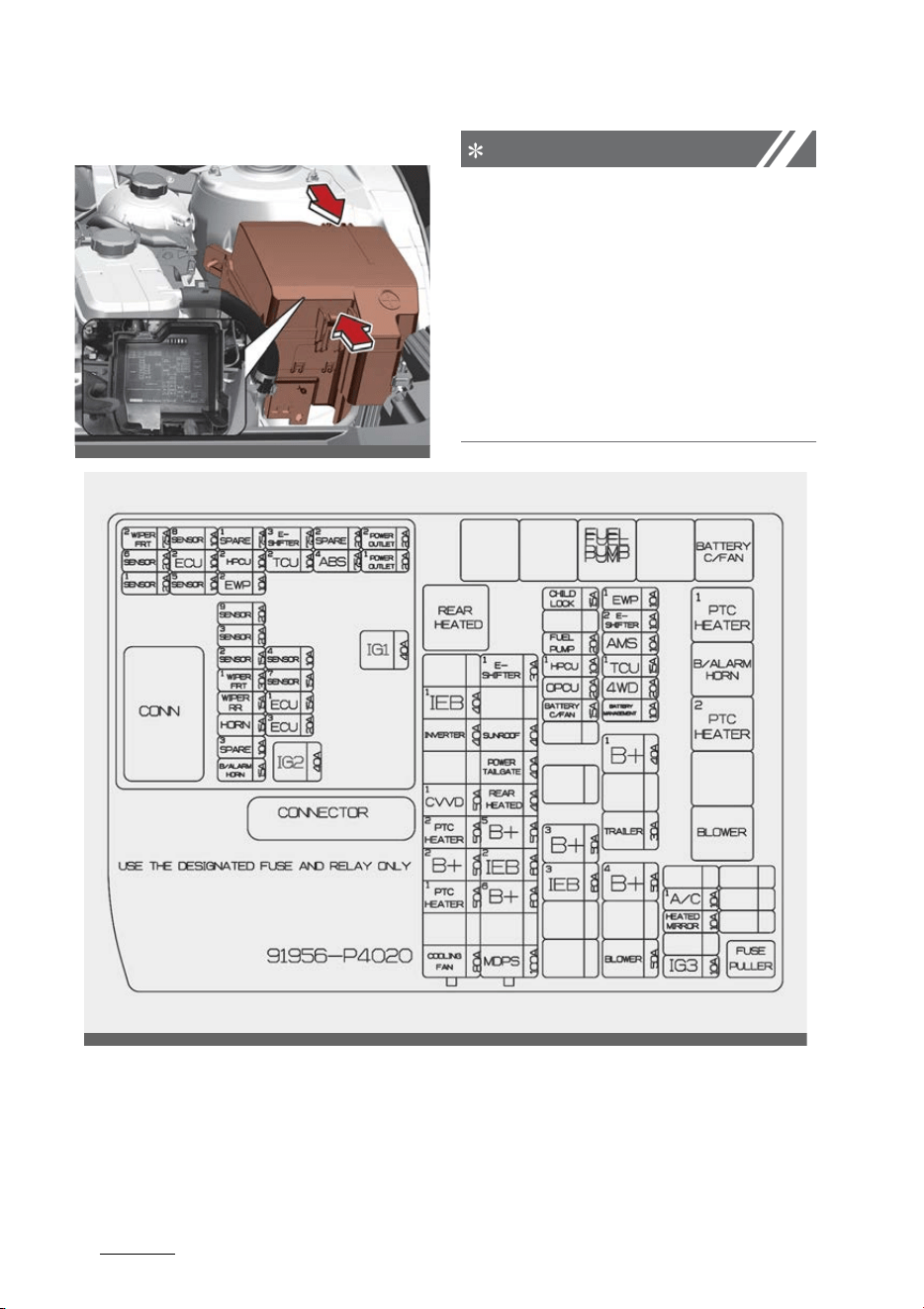
Maintenance
608
Fuses
Engine compartment fuse panel
NOTICE
Not all fuse panel descriptions in this
manual may be applicable to your
vehicle. It is accurate at the time of
printing. When you inspect the fuse
panel in your vehicle, refer to the
fuse panel label on the inside of the
fuse cover. This diagram will provide
you with the specific information
for your vehicles.
OMQ4AH070018
OMQ4070113

61
8
8
Maintenance Fuses
E/R Junction Block
Fuse Name Fuse rating Circuit Protected
COOLING FAN 80A Cooling Fan Motor
PTC HEATER1 50A PTC (Positive Temperature Coefficient) Heater1 Relay
B+2 50A ICU Junction Block (IPS)
PTC HEATER2 50A PTC (Positive Temperature Coefficient) Heater2 Relay
CVVD1 50A CVVD Actuator
INVERTER 40A AC Inverter
IEB1 40A IEB Unit
MDPS1 100A
MDPS (Motor Driven Power Steering) Unit
* MDPS (Motor Driven Power Steering) is same as EPS
(Electric Power Steering).
B+6 60A PCB Junction Block (Fuse - IG1, IG2)
IEB2 60A IEB Unit
B+5 50A
ICU Junction Block (Fuse - 2nd ROW SEAT FOLDING (RH), P/
WINDOW (LH), P/SEAT (DRV), P/SEAT(PASS), S/HEATER
(REAR LH))
REAR HEATED 40A Rear Heated Relay
POWER TAILGATE 40A Power Tail Gate Unit
SUNROOF 40A Sunroof Motor (Glass)
E-SHIFTER1 30A SBW (Shift By Wire) Control Unit
IEB3 60A IEB Unit
B+3 50A ICU Junction Block (IPS)
OPCU 20A OPU
HPCU1 10A HPCU (Hybrid Power Control Unit)
FUEL PUMP 20A Fuel Pump Relay
CHILD LOCK 15A PCB Junction Block (Child Lock/Unlock Relay)
BLOWER 50A Blower Relay
B+4 50A
ICU Junction Block (Fuse - AMP, OBC, IG3 1, S/HEATER
(FRT), P/WINDOW (RH), 2nd ROW SEAT FOLDING (LH))
TRAILER 30A Trailer Module
B+1 40A
ICU Junction Block (Fuse - BRAKE SWITCH, IBU2, S/HEATER
(REAR RH), Charger Lock, AIR BAG2, MODULE9, START,
DOOR LOCK, TAILGATE OPEN, Long Term Load Latch Relay)
BATTERY MANAGEMENT 10A Battery System Assembly
4WD 20A 4WD (4 Wheel Drive) ECU
TCU1 15A TCM (Transmission Control Module)
AMS 10A Battery Sensor

Maintenance
628
Fuses
PCB Junction Block
E-SHITER2 10A SBW (Shift By Wire) Control Unit, Electronic Shift Dial
EWP1 10A Electronic Water Pump (Engine)
IG3 10A OBC Unit, Battery System Assembly
HEATED MIRROR 10A
Front Air Conditioner Control Panel, Driver/Passenger
Power Outside Mirror
A/C1 10A Not Used
Fuse Name Fuse rating Circuit Protected
Fuse Name Fuse rating Circuit Protected
IG2 40A IG2 Relay
IG1 40A IG1 Relay, ACC Relay
WIPER FRT2 7.5A IBU (Integrated Body Control Unit)
SENSOR6 20A Oxygen Sensor (Down)
SENSOR1 20A Ignition Coil #1~#4
SENSOR8 10A OPU
ECU2 10A ECM (Engine Control Module), CVVD Actuator
SENSOR5 10A E/R Junction Block (Fuel Pump Relay)
HPCU2 10A HPCU (Hybrid Power Control Unit)
EWP2 10A Electronic Water Pump, Electronic Water Pump (HEV)
SENSOR9 20A Not Used
SENSOR3 20A ECM (Engine Control Module)
SENSOR2 15A Active Purge Pump
WIPER FRT1 30A Front Wiper Motor, Front Wiper (Low) Relay
WIPER RR 15A Rear Wiper Relay, Rear Wiper Motor
HORN 15A Horn Relay
B/ALARM HORN 15A Burglar Alarm Horn Relay
E-SHIFTER3 7.5A SBW (Shift By Wire) Control Unit
TCU2 10A TCM (Transmission Control Module)
SENSOR4 10A
Purge Control Solenoid Valve, Oil Control Valve #1/#2
(Intake/Exhaust), Oil Pump Solenoid Valve, RCV (Recircula
-
tion Valve Control) Control Solenoid Valve, Cooling Fan
Motor, ELCM (EVAP. Leak Check Module)
SENSOR7 15A Oxygen Sensor (Up)
ECU1 15A ECM (Engine Control Module)
ECU3 20A ECM (Engine Control Module)
ABS4 7.5A IEB Unit

63
8
8
Maintenance Fuses
Relay
Refer to the following table for
the relay type.
POWER
OUTLET2
20A Rear Console Power Outlet
POWER OUTLET1 20A Luggage Power Outlet
Fuse Name Fuse rating Circuit Protected
Relay Name Type
Fuel Pump Relay MICRO
Battery C/Fan Relay MICRO
PTC Heater 1 Relay MICRO
B/Alarm Horn Relay MICRO
PTC Heater 2 Relay MICRO
Blower Relay MICRO
Rear Heated Relay MINI
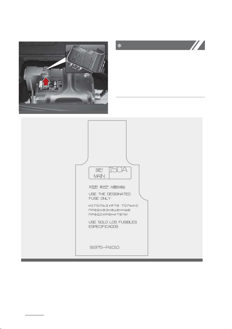
Maintenance
648
Fuses
Engine compartment fuse panel (Battery terminal cover)
NOTICE
Not all fuse panel descriptions in this
manual may be applicable to your
vehicle. It is accurate at the time of
printing. When you inspect the fuse
panel in your vehicle, refer to the
fuse panel label.
OMQ4H070015
OMQ4H070019

65
8
8
Maintenance Light bulbs
Light bulbs
Light bulbs are installed in various
parts of the vehicle to provide light
-
ing inside and outside the vehicle as
well as to alert other vehicles.
Bulb replacement precaution
Please keep extra bulbs on hand
with appropriate wattage ratings in
case of emergencies.
Refer to "Bulb wattage" on page 9-
5.
When changing lamps, first turn off
the vehicle at a safe place, firmly
apply the parking brake and detach
the battery's negative (-) terminal.
WARNING
Working on the lights
Prior to working on the light, firmly
apply the parking brake, ensure that
turn the ENGINE START/STOP but
-
ton and turn off the lights to avoid
sudden movement of the vehicle
and burning your fingers or receiv
-
ing an electric shock.
Use only bulbs of the specified
wattage.
CAUTION
Light replacement
Be sure to replace the burned-out
bulb with one of the same wattage
rating. Otherwise, it may cause
damage to the fuse or electric wir
-
ing system.
Fully install light bulbs and any parts
used to secure them. Failure to do
so may result in heat damage, fire,
or water entering the headlamp
unit. This may damage the head
-
lamps or cause condensation to
build up on the lens. To prevent
damage or fire, make sure bulbs are
fully seated and locked.
CAUTION
Headlamp lens
To prevent damage, do not clean the
headlamp lens with chemical sol
-
vents or strong detergents.
NOTICE
䳜 If the light bulb or lamp connector
is removed while the lamp is still
on, the fuse box's electronic sys
-
tem may log it as a malfunction.
Therefore, a lamp malfunction
incident may be recorded as a
Diagnostic Trouble Code (DTC) in
the fuse box.
䳜 It is normal for an operating lamp
to flicker momentarily. This is due
to a stabilization function of the
vehicle's electronic control device.
If the lamp lights up normally
after momentarily blinking, then
it is functioning as normal.
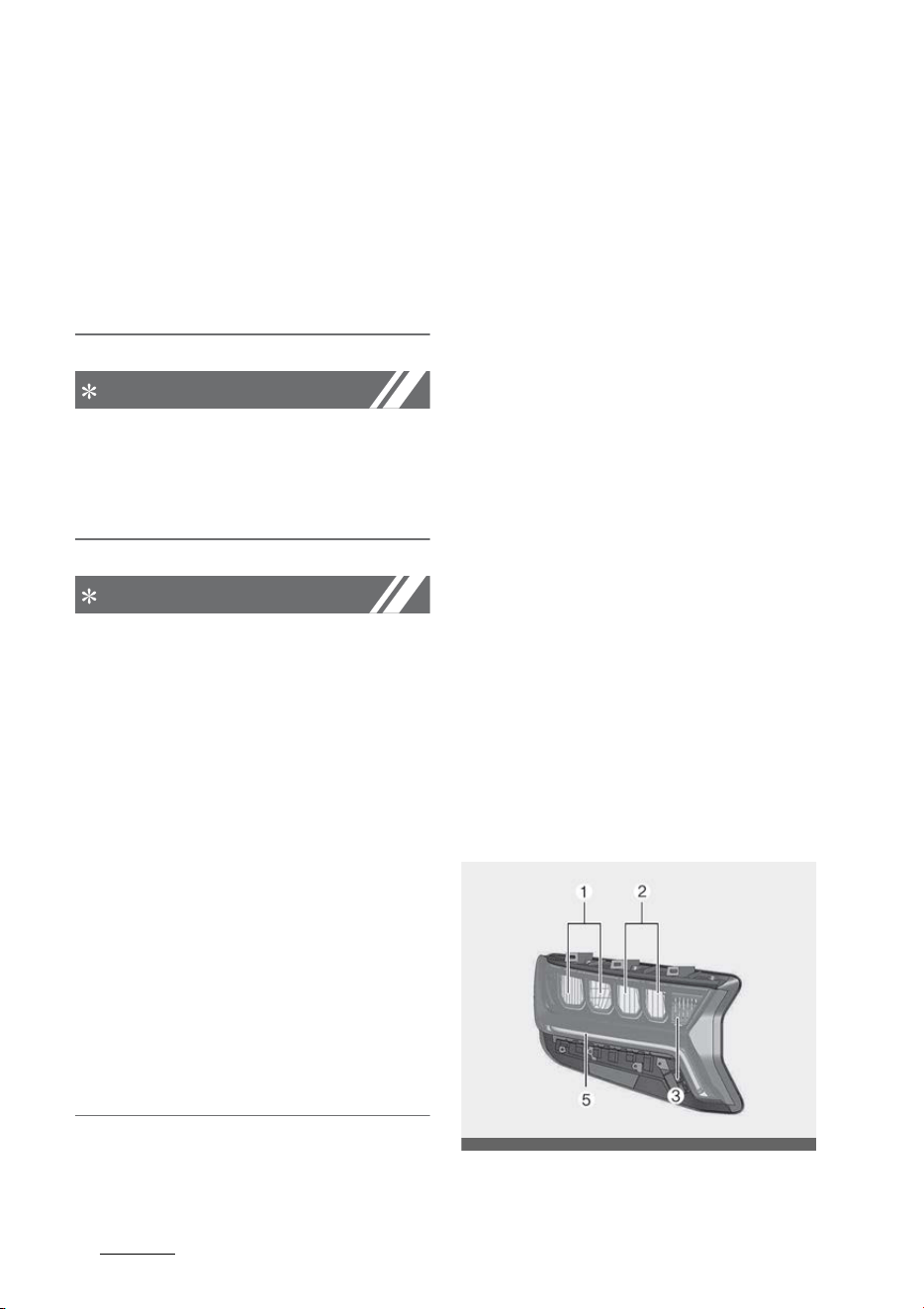
Maintenance
668
Light bulbs
However, if the lamp continues to
flicker several times or turns off
completely, there may be an error
in the vehicle's electronic control
device. Please have the vehicle
checked by an authorized Kia
dealer immediately.
NOTICE
Have the headlamp aiming adjusted
by an authorized Kia dealer after an
accident or after the headlamp
assembly is reinstalled.
NOTICE
You can find moisture inside the lens
of lamps after a car wash or driving
in the rain. It is a natural event
caused by the temperature differ
-
ence between the inside and the
outside of the lamp and does not
mean there is a problem with its
functions. The moisture inside the
lamp would disappear if you drive
the vehicle with the headlamp
turned on. However, the level at
which the moisture is removed may
differ depending on the size/loca
-
tion/condition of the lamp. If the
moisture continues to stay inside
the lamp, have the vehicle checked
by an authorized Kia dealer.
If you don't have the necessary
tools, the correct bulbs and the
expertise, consult an authorized Kia
dealer. In many cases, it is difficult
to replace vehicle light bulbs
because other parts of the vehicle
must be removed before you can
get to the bulb. This is especially
true if you have to remove the
headlamp assembly to get to the
bulb(s).
Removing/installing the headlamp
assembly can result in damage to
the vehicle. If non-genuine parts or
substandard bulbs are used, it may
lead to blowing a fuse or other wir
-
ing damages.
Do not install extra lamps or LEDs to
the vehicle. If additional lights are
installed, it may lead to lamp mal
-
functions and flickering. Addition
-
ally, the fuse box and other wiring
may be damaged.
Light bulb position (Front)
Headlamp 䳍 Type A
OMQ4070045
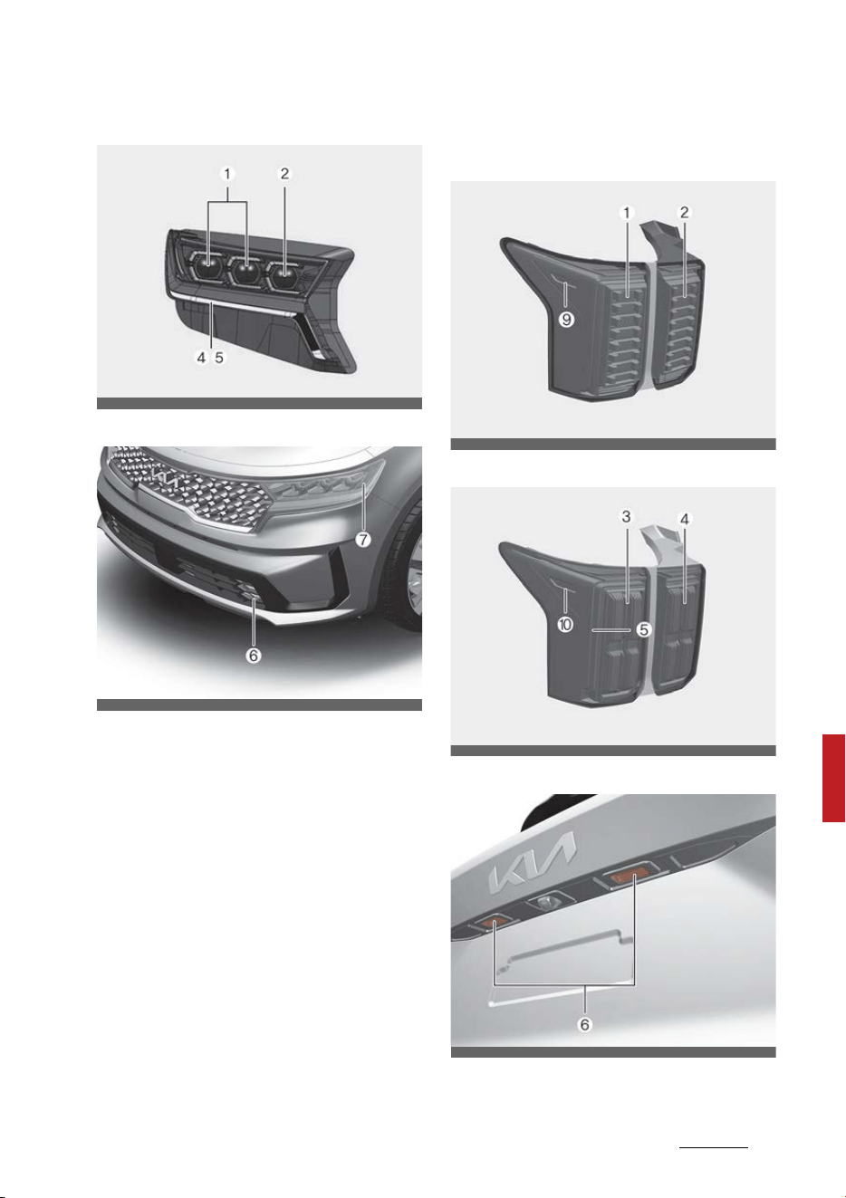
67
8
8
Maintenance Light bulbs
Headlamp 䳍 Type B
Fog lamp
1. Headlamp (Low) (LED type)
2. Headlamp (High) (LED type)
3. Front turn signal lamp (Bulb type)
4. Front turn signal lamp (LED type)
5. Day time running lamp/Position
lamp (LED type)
6. Front fog lamp (LED type)
7. Front side marker lamp (LED
type)
Light bulb position (Rear)
Rear combination lamp - Type A
Rear combination lamp - Type B
License plate lamp
OMQ4070042
OMQ4AH071048
OMQ4AH070057
OMQ4AH070056
OMQ4PH071052
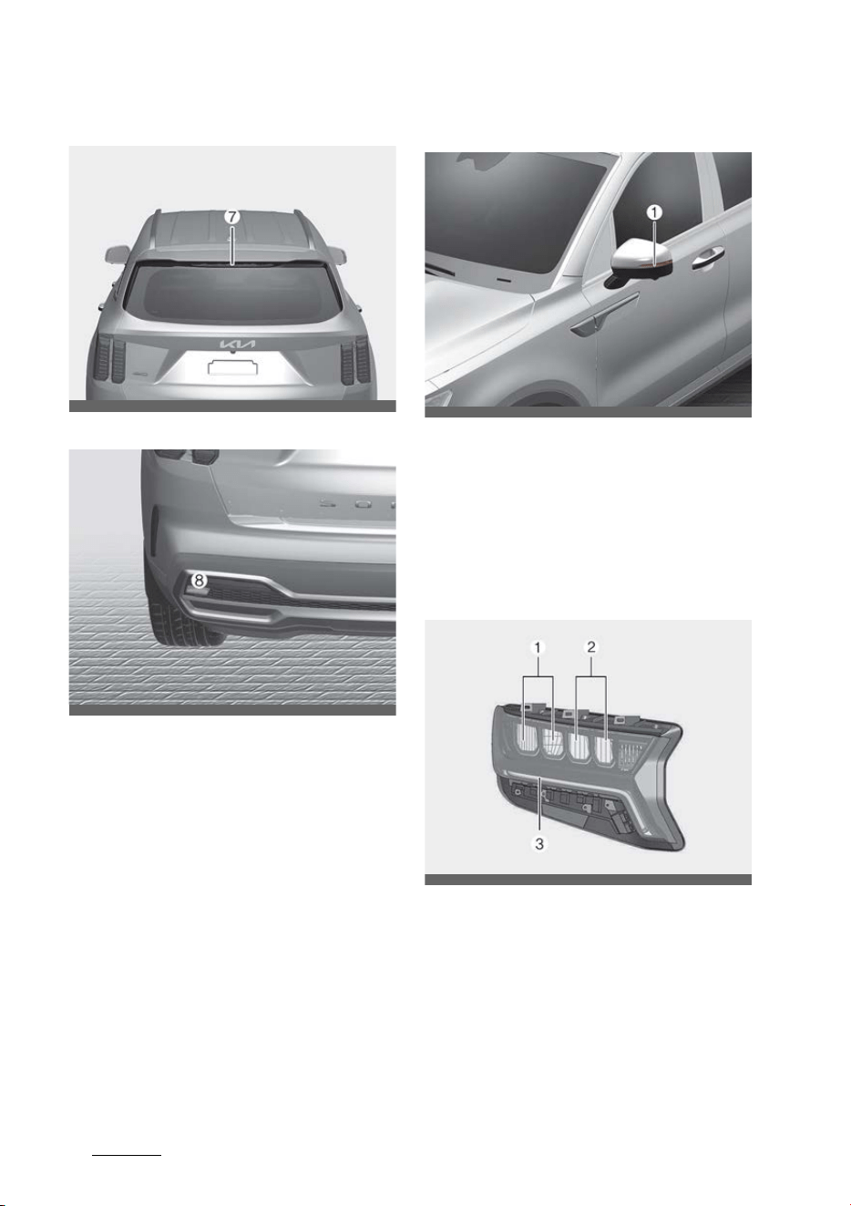
Maintenance
688
Light bulbs
High mounted stop lamp
Reversing lamp
1. Stop and taillamp (Bulb type)
2. Rear turn signal lamp (Bulb type)
3. Stop and taillamp (LED type)
4. Rear turn signal lamp (LED type)
5. Taillamp (LED type)
6. License plate lamp (LED type)
7. High mounted stop lamp (LED
type)
8. Reversing lamp (Bulb type)
9. Rear side marker lamp (Bulb type)
10.Rear side marker lamp (LED
type)
Light bulb position (Side)
1. Side repeater lamp (LED type)
Replacing headlamp (Low beam/
High beam), position lamp/daytime
running lamp, turn signal lamp (LED
type)
Type A
OMQ4PH071058
OMQ4070084L
OMQ4070062
OMQ4070064
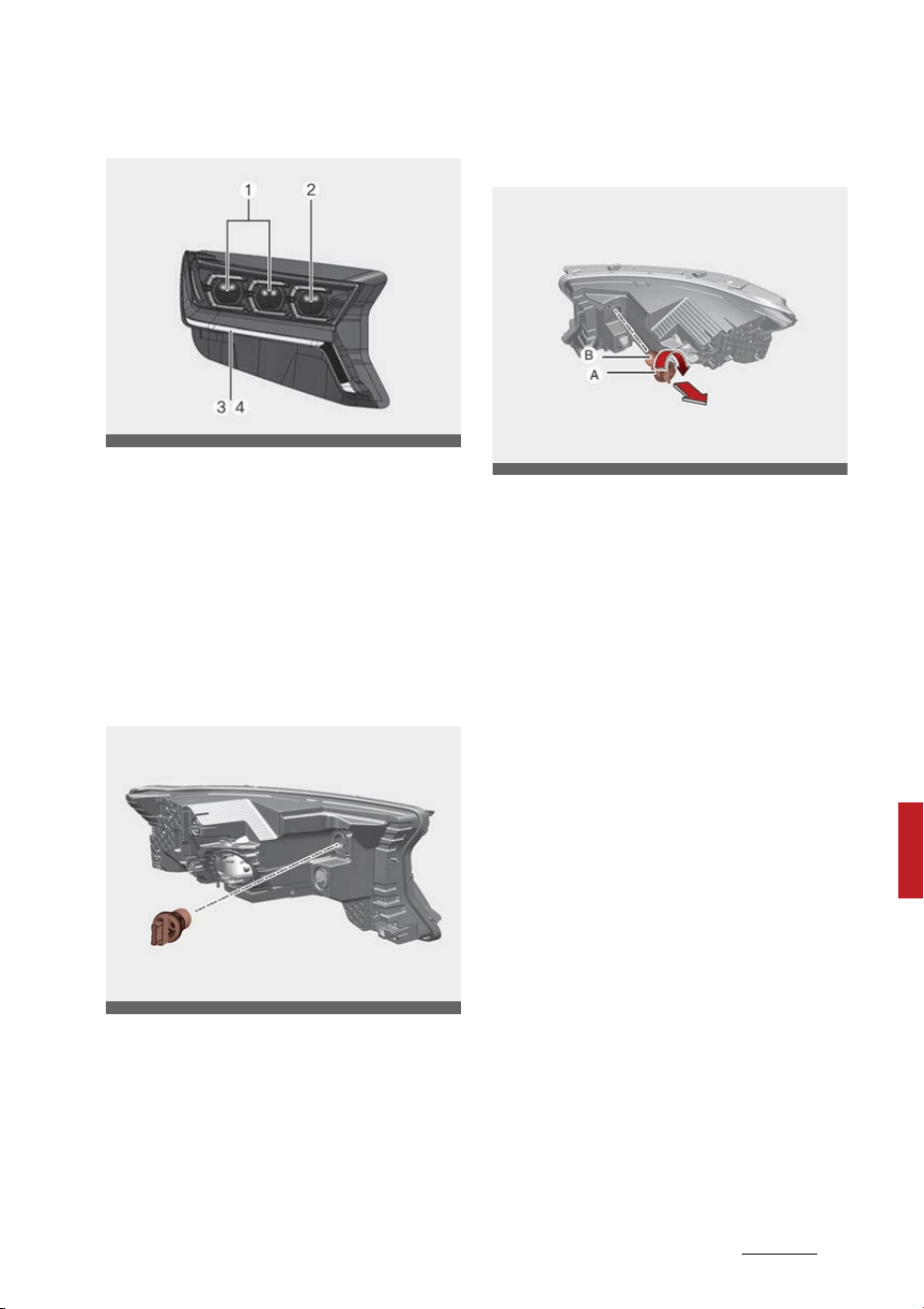
69
8
8
Maintenance Light bulbs
Type B
If the headlamp LED (1,2), daytime
running lamp LED (3) and turn signal
lamp LED (4) does not operate, have
your vehicle checked by a profes
-
sional workshop. Kia recommends to
visit an authorized Kia dealer.
Replacing front turn signal lamp
(Bulb type)
1. Turn off vehicle and disconnect
the negative terminal from the
battery.
2. Remove the socket (A) from the
assembly by turning the socket
counterclockwise until the tabs on
the socket align with the slots on
the assembly.
3. Remove the bulb (B) from the
socket (A) by pressing it in and
rotating it counterclockwise until
the tabs on the bulb align with the
slots in the socket. Pull the bulb
out of the socket
4. Insert a new bulb by inserting it
into the socket and rotating it
until it locks into place.
5. Install the socket in the assembly
by aligning the tabs on the socket
with the slots in the assembly.
Push the socket into the assem
-
bly and turn the socket clockwise.
6. Connect the negative terminal
from the battery.
OMQ4070065
OMQ4070067
OMQ4070106L
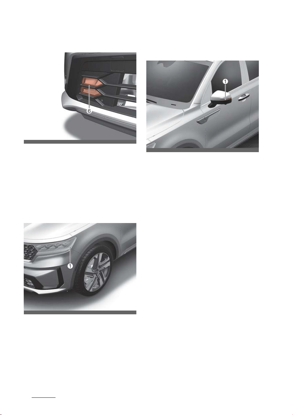
Maintenance
708
Light bulbs
Replacing front fog lamp (LED type)
If the front fog lamp (6) does not
operate, have your vehicle checked
by a professional workshop. Kia rec
-
ommends to visit an authorized Kia
dealer.
Replacing front side marker lamp
bulb (LED type)
If the front side marker lamp LED
(1) does not operate, have the vehi
-
cle checked by an authorized Kia
dealer.
Replacing side repeater lamp (LED
type)
If the Side repeater lamp (LED) (1)
does not operate, have your vehicle
checked by a professional workshop.
Kia recommends to visit an autho
-
rized Kia dealer.
The LED lamp cannot be replaced as
a single unit because it is an inte
-
grated unit. The LED lamp has to be
replaced with the unit.
A skilled technician should check or
repair the Side repeater lamp (LED),
for it may damage related parts of
the vehicle.
OMQ4070048
OMQ4PH071110
OMQ4070062
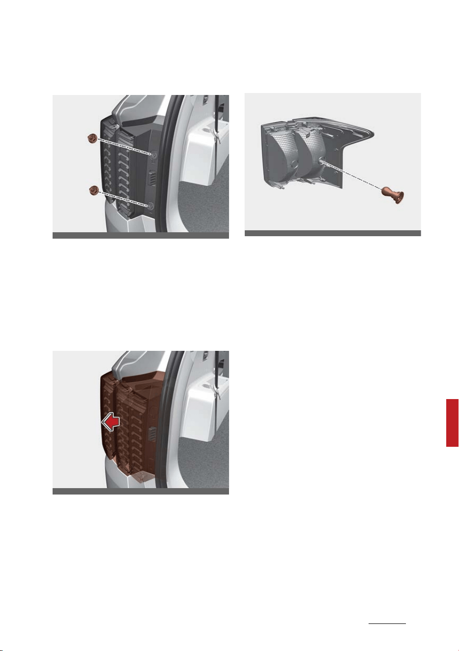
71
8
8
Maintenance Light bulbs
Replacing stop and taillamp (Bulb
type)
1. Turn off vehicle and disconnect
the negative terminal from the
battery.
2. Open the liftgate.
3. Open the service cover.
4. Loosen the light assembly retain
-
ing screws with a cross-tip screw
driver.
5. Remove the rear combination
lamp assembly from the body of
the vehicle.
6. Disconnect the rear combination
lamp connector.
7. Remove the socket from the
assembly by turning the socket
counterclockwise until the tabs on
the socket align with the slots on
the assembly.
8. Remove the bulb from the socket
by pressing it in and rotating it
counterclockwise until the tabs on
the bulb align with the slots in the
socket.
Pull the bulb out of the socket.
9. Insert a new bulb by inserting it
into the socket and rotating it
until it locks into place.
10.Install the socket in the assembly
by aligning the tabs on the socket
with the slots in the assembly.
Push the socket into the assem
-
bly and turn the socket clockwise.
11.Install the rear combination lamp
assembly to the body of the vehi
-
cle.
12.Install the service cover.
OMQ4070060
OMQ4070061
OMQ4070054
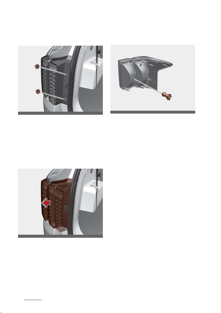
Maintenance
728
Light bulbs
Replacing rear turn signal lamp
(Bulb type)
1. Turn off vehicle and disconnect
the negative terminal from the
battery.
2. Open the liftgate.
3. Open the service cover.
4. Loosen the light assembly retain
-
ing screws with a cross-tip screw
driver.
5. Remove the rear combination
lamp assembly from the body of
the vehicle.
6. Disconnect the rear combination
lamp connector.
7. Remove the socket from the
assembly by turning the socket
counterclockwise until the tabs on
the socket align with the slots on
the assembly.
8. Remove the bulb from the socket
by pressing it in and rotating it
counterclockwise until the tabs on
the bulb align with the slots in the
socket.
Pull the bulb out of the socket.
9. Insert a new bulb by inserting it
into the socket and rotating it
until it locks into place.
10.Install the socket in the assembly
by aligning the tabs on the socket
with the slots in the assembly.
Push the socket into the assem
-
bly and turn the socket clockwise.
11.Install the rear combination lamp
assembly to the body of the vehi
-
cle.
12.Install the service cover.
OMQ4070060
OMQ4070061
OMQ4070055
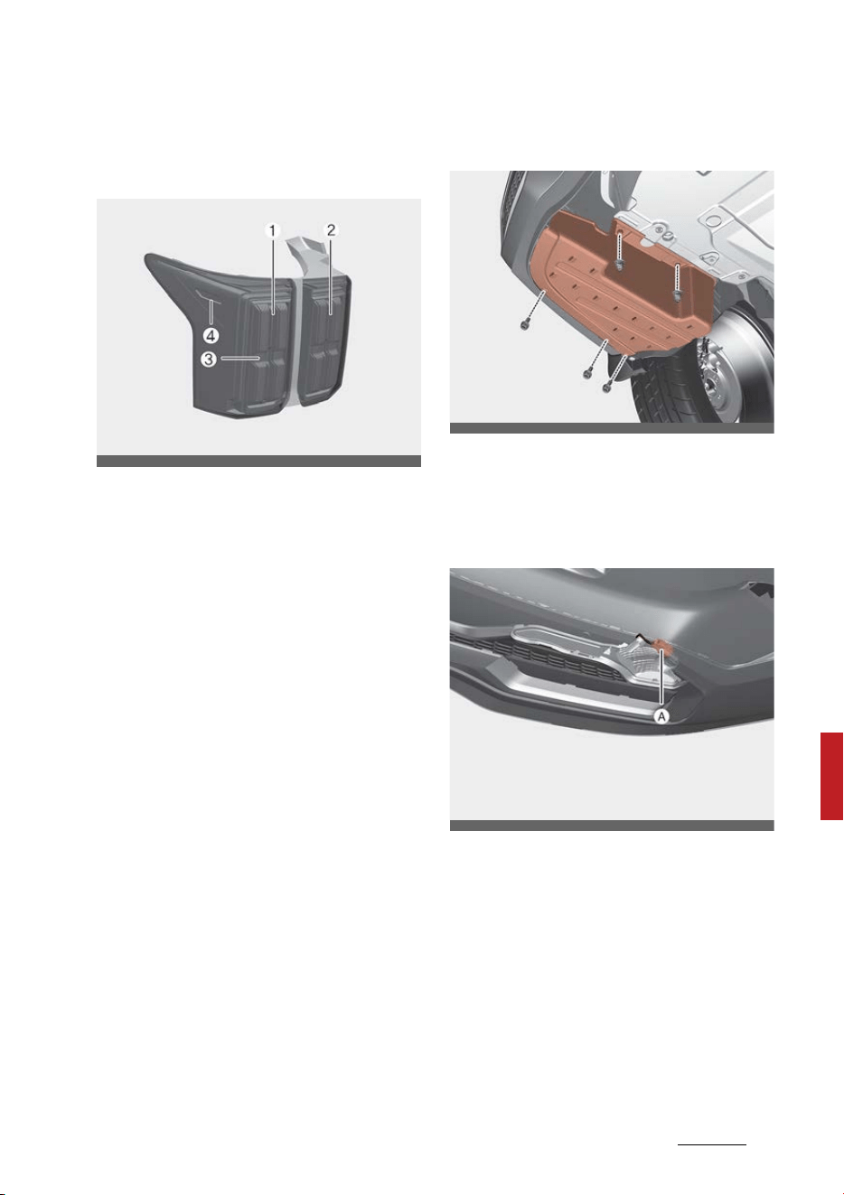
73
8
8
Maintenance Light bulbs
Replacing rear turn signal lamp,
stop and taillamp, rear side marker
lamp (LED type)
If the stop and taillamp (1), rear
turn signal lamp (2), taillamp (3),
and rear side marker lamp (4) do not
operate, have your vehicle checked
by a professional workshop. Kia rec
-
ommends to visit an authorized Kia
dealer.
The LED lamp cannot be replaced as
a single unit because it is an inte
-
grated unit. The LED lamp has to be
replaced with the unit.
A skilled technician should check or
repair the stop and taillamp (LED),
for it may damage related parts of
the vehicle.
Replacing reversing lamp (bulb
type)
1. Turn off vehicle and disconnect
the negative terminal from the
battery.
2. Remove the plastic tabs with a
flat-tip screw driver.
3. Loosen the plastic retaining
screws and remove the under
panel cover.
4. Disconnect the rear reversing
lamp connector (A).
5. Remove the socket (A) from the
assembly by turning the socket
counterclockwise until the tabs on
the socket align with the slots on
the assembly.
OMQ4AH070059
OMQ4070105L
OMQ4070107L
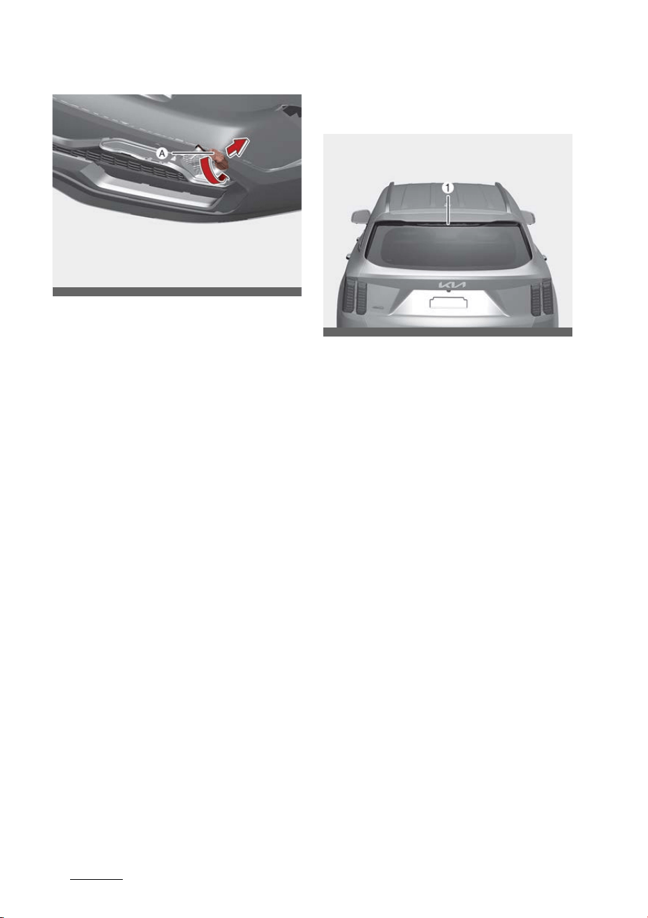
Maintenance
748
Light bulbs
6. Remove the bulb from the socket
by pressing it in and rotating it
counterclockwise until the tabs on
the bulb align with the slots in the
socket. Pull the bulb out of the
socket.
7. Insert a new bulb by inserting it
into the socket and rotating it
until it locks into place.
8. Install the socket in the assembly
by aligning the tabs on the socket
with the slots in the assembly.
Push the socket into the assem
-
bly and turn the socket clockwise.
9. Connect the rear back up lamp
connector.
10.Tighten the plastic retaining
screws.
11.Install the plastic tabs and the
under panel cover.
Replacing high mounted stop lamp
(LED type)
If the high mounted stop lamp (LED)
(1) does not operate, have your
vehicle checked by an authorized Kia
dealer.
The LED lamps cannot be replaced
as a single component because it is
an integrated unit. The LED lamps
have to be replaced with the unit.
A skilled technician should check or
repair the High Mounted Stop Lamp
(LED), for it may damage related
parts of the vehicle.
OMQ4070108L
OMQ4PH071053
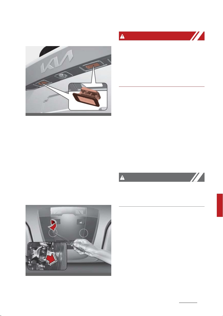
75
8
8
Maintenance Light bulbs
Replacing license plate lamp (LED
type)
If the license plate lamp does not
operate, have your vehicle checked
by an authorized Kia dealer. The LED
lamp cannot be replaced as a single
unit because it is an integrated unit.
The LED lamp has to be replaced
with the unit. A skilled technician
should check or repair the map lamp
(LED), for it may damage related
parts of the vehicle.
Replacing map lamp (Bulb type)
WARNING
Interior lamps
Prior to working on the Interior
lamps, ensure that the "OFF" button
is depressed to avoid burning your
fingers or receiving an electric
shock.
1. Turn off vehicle and disconnect
the negative terminal from the
battery.
2. Using a flat-blade screwdriver,
gently pry the lens cover from
lamp housing.
3. Remove the bulb by pulling it
straight out.
4. Install a new bulb in the socket.
5. Align the lens cover tabs with the
lamp housing notches and snap
the lens into place.
CAUTION
Be careful not to dirty or damage
the lens, lens tab, and plastic hous
-
ings.
OMQ4PH071047
OMQ4AH070049
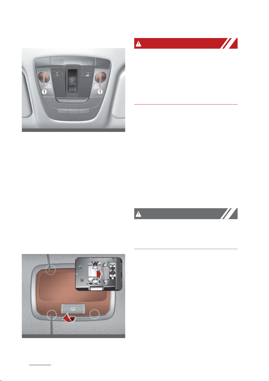
Maintenance
768
Light bulbs
Replacing map lamp (LED type)
If the map lamp (LED) (1) does not
operate, have your vehicle checked
by an authorized Kia dealer.
The LED lamp cannot be replaced as
a single unit because it is an inte
-
grated unit. The LED lamp has to be
replaced with the unit.
A skilled technician should check or
repair the map lamp (LED), for it
may damage related parts of the
vehicle.
Replacing room lamp (Bulb type)
WARNING
Interior lamps
Prior to working on the Interior
lamps, ensure that the "OFF" button
is depressed to avoid burning your
fingers or receiving an electric
shock.
1. Turn off vehicle and disconnect
the negative terminal from the
battery.
2. Using a flat-blade screwdriver,
gently pry the lens cover from
lamp housing.
3. Remove the bulb by pulling it
straight out.
4. Install a new bulb in the socket.
5. Align the lens cover tabs with the
lamp housing notches and snap
the lens into place.
CAUTION
Be careful not to dirty or damage
the lens, lens tab, and plastic hous
-
ings.
OMQ4041591N
OMQ4070043
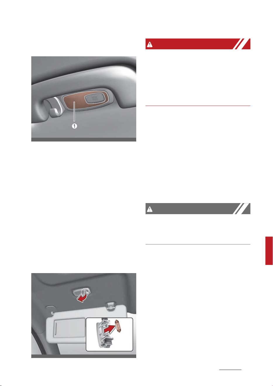
77
8
8
Maintenance Light bulbs
Replacing personal lamp (LED type)
(if equipped)
If the personal lamp (LED) (1) does
not operate, have your vehicle
checked by an authorized Kia dealer.
The LED lamp cannot be replaced as
a single unit because it is an inte
-
grated unit. The LED lamp has to be
replaced with the unit.
A skilled technician should check or
repair the personal lamp (LED), for it
may damage related parts of the
vehicle.
Replacing vanity mirror lamp (Bulb
type)
WARNING
Interior lamps
Prior to working on the Interior
lamps, ensure that the "OFF" button
is depressed to avoid burning your
fingers or receiving an electric
shock.
1. Turn off vehicle and disconnect
the negative terminal from the
battery.
2. Using a flat-blade screwdriver,
gently pry the lamp assembly
from interior.
3. Remove the bulb by pulling it
straight out.
4. Install a new bulb in the socket.
5. Install the lamp assembly to inte
-
rior.
CAUTION
Be careful not to dirty or damage
the lens, lens tab, and plastic hous
-
ings.
OMQ4070044
OMQ4070050
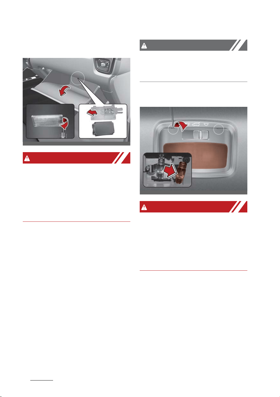
Maintenance
788
Light bulbs
Replacing glove box lamp (Bulb
type)
WARNING
Interior lamps
Prior to working on the Interior
lamps, ensure that the "OFF" button
is depressed to avoid burning your
fingers or receiving an electric
shock.
1. Turn off vehicle and disconnect
the negative terminal from the
battery.
2. Using a flat-blade screwdriver,
gently pry the lamp assembly
from interior.
3. Remove the cover from the lamp
assembly.
4. Remove the bulb by pulling it
straight out.
5. Install a new bulb in the socket.
6. Install the cover to the lamp
assembly.
7. Install the lamp assembly to inte
-
rior.
CAUTION
Be careful not to dirty or damage
the lens, lens tab, and plastic hous
-
ings.
Replacing luggage lamp (Bulb type)
WARNING
Interior lamps
Prior to working on the Interior
lamps, ensure that the "OFF" button
is depressed to avoid burning your
fingers or receiving an electric
shock.
1. Turn off vehicle and disconnect
the negative terminal from the
battery.
2. Using a flat-blade screwdriver,
gently pry the lamp assembly
from interior.
3. Remove the cover from the lamp
assembly.
4. Remove the bulb by pulling it
straight out.
5. Install a new bulb in the socket.
OMQ4070085L
OMQ4070046
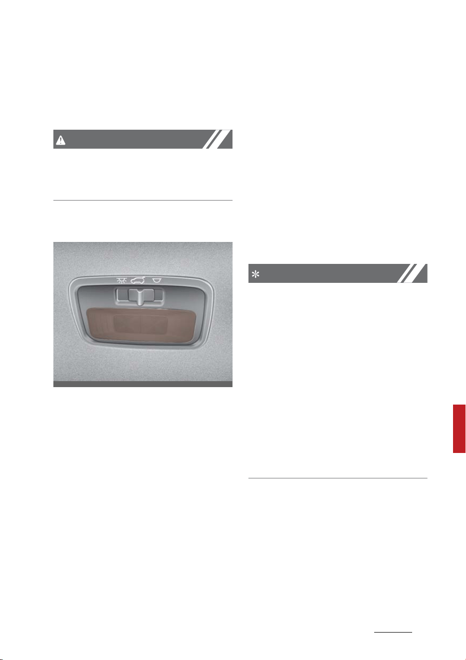
79
8
8
Maintenance Appearance care
6. Install the cover to the lamp
assembly.
7. Install the lamp assembly to inte
-
rior.
CAUTION
Be careful not to dirty or damage
the lens, lens tab, and plastic hous
-
ings.
Replacing luggage lamp (LED type)
If the luggage lamp bulb/LED does
not operate, we recommend that
the system be checked by a profes
-
sional workshop.
Appearance care
Use the information in the following
sections to keep the exterior and
interior of your vehicle clean.
Exterior care
Use the information in the following
sections to maintain the exterior of
your vehicle. Keeping the exterior
clean is not only aesthetically pleas
-
ing, but it also helps to prolong the
life of the vehicle.
NOTICE
If you park the vehicle around a
stainless signboard or windshield
building etc., the plastic exterior
trim (bumper, spoiler, garnish, lamp,
outside mirror etc.) may be dam
-
aged by reflected sunlight from the
external structure. To avoid damag
-
ing the plastic exterior trim, park
the vehicle away from the areas
where the reflected light may occur
or use a vehicle cover. (Depending on
the vehicle, the type of exterior trim
applied such as spoiler may differ.)
Exterior general caution
It is very important to follow the
label directions when using any
chemical cleaner or polish. Read all
warning and caution statements
that appear on the label.
OMQ4040464

Maintenance
808
Appearance care
Finish maintenance
Washing
To help protect your vehicle's finish
from rust and deterioration, wash it
thoroughly and frequently at least
once a month with lukewarm or cold
water.
If you use your vehicle for off-road
driving, you should wash it after
each off-road trip. Pay special
attention to the removal of any
accumulation of salt, dirt, mud, and
other foreign materials. Make sure
the drain holes in the lower edges of
the doors and rocker panels are
kept clear and clean.
Insects, tar, tree sap, bird droppings,
industrial pollution and similar
deposits can damage your vehicle's
finish if not removed immediately.
Even prompt washing with plain
water may not completely remove
all these deposits. A mild soap, safe
for use on painted surfaces, may be
used.
After washing, rinse the vehicle
thoroughly with lukewarm or cold
water. Do not allow soap to dry on
the finish.
After washing the vehicle, test the
brakes while driving slowly to see if
they have been affected by water. If
braking performance is impaired,
dry the brakes by applying them
lightly while maintaining a slow for
-
ward speed.
CAUTION
䳜 Do not use strong soap, chemical
detergents or hot water, and do
not wash the vehicle in direct sun
-
light or when the body of the
vehicle is warm.
䳜 Be careful when washing the side
windows of your vehicle, espe
-
cially with high-pressure water.
Water may leak through the win
-
dows and wet the interior.
䳜 To prevent damage to the plastic
parts and lamps, do not clean with
chemical solvents or strong
detergents.
WARNING
After washing the vehicle, test the
brakes while driving slowly to see if
they have been affected by water. If
braking performance is impaired,
dry the brakes by applying them
lightly while maintaining a slow for
-
ward speed.
High-pressure washing
When using high-pressure washers,
make sure to maintain sufficient
distance from the vehicle.
Insufficient clearance or excessive
pressure can lead to component
damage or water penetration.
Do not spray the camera, sensors or
its surrounding area directly with a
high pressure washer. Shock applied
from high pressure water may
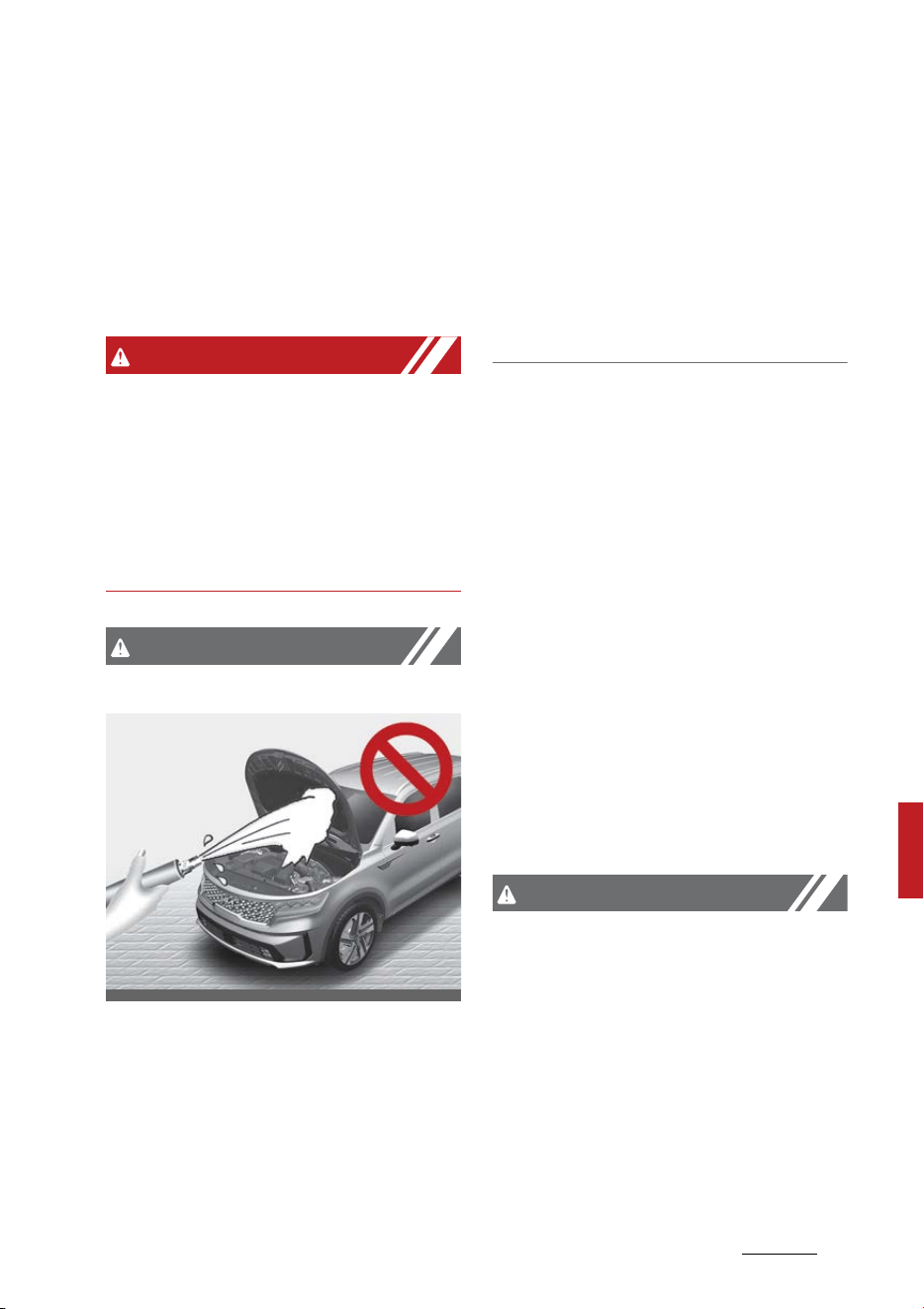
81
8
8
Maintenance Appearance care
cause the device to not operate
normally.
Do not bring the nozzle tip close to
boots (rubber or plastic covers) or
connectors as they may be dam
-
aged if they come into contact with
high pressure water.
WARNING
After washing the vehicle, test the
brakes while driving slowly to see if
they have been affected by water. If
braking performance is impaired,
dry the brakes by applying them
lightly while maintaining a slow for
-
ward speed.
CAUTION
Wetting engine compartment
䳜 Water washing in the engine com
-
partment including high pressure
water washing may cause the
failure of electrical circuits located
in the engine compartment.
䳜 Never allow water or other liquids
to come in contact with electrical/
electronic components and air
duct inside the vehicle as this may
damage them.
䳜 After the vehicle has been
washed, brake carefully while
paying attention to the traffic
conditions until the braking effect
has been fully restored.
Waxing
Wax the vehicle when water will no
longer bead on the paint.
Always wash and dry the vehicle
before waxing. Use a good quality
liquid or paste wax, and follow the
manufacturer's instructions. Wax all
metal trim to protect it and to
maintain its luster.
Removing oil, tar, and similar mate
-
rials with a spot remover will usually
strip the wax from the finish. Be
sure to re-wax these areas even if
the rest of the vehicle does not yet
need waxing.
Be careful not to touch the lens
when waxing the lamps.
CAUTION
Drying vehicle
䳜 Wiping dust or dirt off the body
with a dry cloth will scratch the
finish.
䳜 Do not use steel wool, abrasive
cleaners, acid detergents or
strong detergents containing high
alkaline or caustic agents on
chrome-plated or anodized alumi
-
num parts. This may result in
OMQ4071086L

Maintenance
828
Appearance care
damage to the protective coating
and cause discoloration or paint
deterioration.
Finish damage repair
Deep scratches or stone chips in the
painted surface must be repaired
promptly. Exposed metal will quickly
rust and may develop into a major
repair expense.
NOTICE
If your vehicle is damaged and
requires any metal repair or
replacement, be sure the body shop
applies anti-corrosion materials to
the parts repaired or replaced.
Bright-metal maintenance
To remove road tar and insects, use
a tar remover, not a scraper or
other sharp object.
To protect the surfaces of bright
metal parts from corrosion, apply a
coating of wax or chrome preserva
-
tive and rub to a high luster.
During winter weather or in coastal
areas, cover the bright metal parts
with a heavier coating of wax or
preservative. If necessary, coat the
parts with non-corrosive petroleum
jelly or other protective compound.
Underbody maintenance
Road salt and other corrosive chem
-
icals are used in cold weather states
to melt snow and prevent ice accu
-
mulation. If these chemicals are not
regularly removed, they will corrode
the vehicle underbody and, over
time, damage many parts: the fuel
lines, the fuel tank retention sys
-
tem, the vehicle's suspension, the
exhaust system, and even the body
frame.
The National Highway Traffic Safety
Administration has warned all vehi
-
cle owners of all brands of the need
to take the following steps:
䳜 Wash the undercarriage of your
vehicle regularly during the winter
and whenever your vehicle has
been exposed to such salts or
chemicals.
䳜 Do a thorough washing of the
undercarriage at the end of the
winter.
䳜 Use professional service techni
-
cians or governmental inspection
stations to annually inspect for
corrosion.
䳜 Immediately seek an inspection of
your vehicle if you become visu
-
ally aware of corrosion flaking or
scaling or if you become aware of
a change in vehicle performance,
such as soft or spongy brakes,
fluids leaking, impairment of
directional control, suspension
noises or rattling metal straps.

83
8
8
Maintenance Appearance care
Aluminum wheel maintenance
The aluminum wheels are coated
with a clear protective finish.
䳜 Do not use any abrasive cleaner,
polishing compound, solvent, or
wire brushes on aluminum
wheels. They may scratch or
damage the finish.
䳜 Clean the wheel when it has
cooled.
䳜 Use only a mild soap or neutral
detergent, and rinse thoroughly
with water. Also, be sure to clean
the wheels after driving on salted
roads. This helps prevent corro
-
sion.
䳜 Avoid washing the wheels with
high speed vehicle wash brushes.
䳜 Do not use any alkaline or acid
detergents It may damage and
corrode the aluminum wheels
coated with a clear protective fin
-
ish.
Corrosion protection
Protecting your vehicle from corro
-
sion
By using the most advanced design
and construction practices to com
-
bat corrosion, we produce vehicles
of the highest quality. However, this
is only part of the job. To achieve
the long-term corrosion resistance
your vehicle can deliver, the owner's
cooperation and assistance is also
required.
Common causes of corrosion
The most common causes of corro
-
sion on your vehicle are:
䳜 Road salt, dirt and moisture that
is allowed to accumulate under
-
neath the vehicle.
䳜 Removal of paint or protective
coatings by stones, gravel, abra
-
sion or minor scrapes and dents
which leave unprotected metal
exposed to corrosion.
High-corrosion areas
If you live in an area where your
vehicle is regularly exposed to cor
-
rosive materials, corrosion protec
-
tion is particularly important. Some
of the common causes of acceler
-
ated corrosion are road salts, dust
control chemicals, ocean air and
industrial pollution.
Moisture breeds corrosion
Moisture creates the conditions in
which corrosion is most likely to
occur. For example, corrosion is
accelerated by high humidity, par
-
ticularly when temperatures are
just above freezing. In such condi
-
tions, the corrosive material is kept
in contact with the vehicle's surface
by moisture that evaporates slowly.
Mud is particularly corrosive
because it dries slowly and holds
moisture in contact with the vehicle.
Although the mud appears to be
dry, it can still retain the moisture
and promote corrosion.
High temperatures can also acceler
-
ate corrosion of parts that are not

Maintenance
848
Appearance care
properly ventilated so the moisture
can be dispersed. For all these rea
-
sons, it is particularly important to
keep your vehicle clean and free of
mud or accumulations of other
materials. This applies not only to
the visible surfaces but particularly
to the underside of the vehicle.
To help prevent corrosion
You can help prevent corrosion from
beginning by observing the follow
-
ing:
Keep your vehicle clean
The best way to prevent corrosion is
to keep your vehicle clean and free
of corrosive materials. Attention to
the underside of the vehicle is par
-
ticularly important.
If you live in a high-corrosion area 䳎
where road salts are used, near the
ocean, areas with industrial pollu
-
tion, acid rain, etc.䳎, you should
take extra care to prevent corrosion.
In winter, hose off the underside of
your vehicle at least once a month
and be sure to clean the underside
thoroughly when winter is over.
When cleaning underneath the vehi
-
cle, give particular attention to the
components under the fenders and
other areas that are hidden from
view. Do a thorough job; just damp
-
ening the accumulated mud rather
than washing it away will accelerate
corrosion rather than prevent it.
Water under high pressure and
steam are particularly effective in
removing accumulated mud and
corrosive materials.
When cleaning lower door panels,
rocker panels and frame members,
be sure that drain holes are kept
open so that moisture can escape
and not be trapped inside to accel
-
erate corrosion.
Keep your garage dry
Don't park your vehicle in a damp,
poorly ventilated garage. This cre
-
ates a favorable environment for
corrosion. This is particularly true if
you wash your vehicle in the garage
or drive it into the garage when it is
still wet or covered with snow, ice or
mud. Even a heated garage can con
-
tribute to corrosion unless it is well
ventilated so moisture is dispersed.
Keep paint and trim in good condi
-
tion
Scratches or chips in the finish
should be covered with "touch-up"
paint as soon as possible to reduce
the possibility of corrosion. If bare
metal is showing through, the
attention of a qualified body and
paint shop is recommended.
Bird droppings: Bird droppings are
highly corrosive and may damage
painted surfaces in just a few hours.

85
8
8
Maintenance Appearance care
Always remove bird droppings as
soon as possible.
Don't neglect the interior
Moisture can collect under the floor
mats and carpeting and cause cor
-
rosion. Check under the mats peri
-
odically to be sure the carpeting is
dry. Use particular care if you carry
fertilizers, cleaning materials or
chemicals in the vehicle.
These should be carried only in
proper containers and any spills or
leaks should be cleaned up, flushed
with clean water and thoroughly
dried.
Interior care
Use the information in the following
sections to maintain the interior of
your vehicle.
Interior general precautions
Prevent chemicals such as perfume,
cosmetic oil, sun cream, hand
cleaner, and air freshener from con
-
tacting the interior parts because
they may cause damage or discolor
-
ation. If they do contact the interior
parts, wipe them off immediately. If
necessary, use a vinyl cleaner, see
product instructions for correct
usage.
CAUTION
Electrical components
Never allow water or other liquids to
come in contact with electrical/elec
-
tronic components inside the vehicle
as this may damage them.
CAUTION
Leather
When cleaning leather products
(steering wheel, seats etc.), use
neutral detergents or low alcohol
content solutions. If you use high
alcohol content solutions or acid/
alkaline detergents, the color of the
leather may fade or the surface
may get stripped off.
Taking care of leather seats
䳜 Vacuum the seat periodically to
remove dust and sand on the
seat. It will prevent abrasion or
damage of the leather and main
-
tain its quality.
䳜 Wipe the leather seat cover often
with dry or soft cloth.
䳜 Sufficient use of a leather protec
-
tive may prevent abrasion of the
cover and helps maintain the
color. Be sure to read the instruc
-
tions and consult a specialist
when using leather coating or
protective agents.
䳜 Leather with bright colors (beige,
cream beige) is easily contami
-

Maintenance
868
Appearance care
nated and clear in appearance.
Clean the seats frequently.
䳜 Avoid wiping with wet cloth. It
may cause the surface to crack.
Cleaning the leather seats
Remove all contaminations
instantly. Refer to instructions
below for removal of each contami
-
nant.
䳜 Cosmetic products (sunscreen,
foundation, etc.)
- Apply cleansing cream on a
cloth and wipe the contami
-
nated point. Wipe off the cream
with a wet cloth and remove
water with a dry cloth.
䳜 Beverages (coffee, soft drink,
etc.)
- Apply a small amount of neutral
detergent and wipe until con
-
taminations do not smear.
䳜 Oil
- Remove oil instantly with
absorbable cloth and wipe with
stain remover for leather only.
䳜 Chewing gum
- Harden the gum with ice and
remove gradually.
Fabric seat cover (if equipped)
Please clean the fabric seats regu
-
larly with a vacuum cleaner in con
-
sideration of fabric material
characteristics. If they are heavily
soiled with beverage stains, etc., use
a suitable interior cleaner. To pre
-
vent damage to seat covers, wipe
off the seat covers down to the
seams with a large wiping motion
and moderate pressure using a soft
sponge or microfiber cloth.
Velcro closures on clothing or sharp
objects may cause snagging or
scratches on the surface of the
seats.
Make sure not to rub such objects
against the surface.
Cleaning the upholstery and inte
-
rior trim
Vinyl
Remove dust and loose dirt from
vinyl with a whisk broom or vacuum
cleaner. Clean vinyl surfaces with a
vinyl cleaner.
Fabric
Remove dust and loose dirt from
fabric with a whisk broom or vac
-
uum cleaner. Clean with a mild soap
solution recommended for uphol
-
stery or carpets. Remove fresh
spots immediately with a fabric spot
cleaner. If fresh spots do not receive
immediate attention, the fabric can
be stained and its color can be
affected. Also, its fire-resistant
properties can be reduced if the
material is not properly maintained.
Using anything but recommended
cleaners and procedures may affect
the fabric's appearance and fire-
resistant properties.

87
8
8
Maintenance Emission control system
Cleaning the lap/shoulder belt web
-
bing
Clean the belt webbing with any
mild soap solution recommended for
cleaning upholstery or carpet. Fol
-
low the instructions provided with
the soap. Do not bleach or re-dye
the webbing because this may
weaken it.
Cleaning the interior window glass
If the interior glass surfaces of the
vehicle become fogged (that is, cov
-
ered with an oily, greasy or waxy
film), they should be cleaned with a
glass cleaner. Follow the directions
on the glass cleaner container.
CAUTION
Rear window
Do not scrape or scratch the inside
of the rear window. This may result
in damage of the rear window
defroster grid.
Emission control system
The emission control system of
your vehicle is covered by a written
limited warranty. Please see the
warranty information contained in
the Warranty & Consumer Informa
-
tion manual in your vehicle.
Your vehicle is equipped with an
emission control system to meet all
applicable emission regulations.
There are three emission control
systems, as follows.
1. Crankcase emission control sys
-
tem
2. Evaporative emission control sys
-
tem
3. Exhaust emission control system
In order to assure the proper func
-
tion of the emission control sys
-
tems, it is recommended that you
have your vehicle inspected and
maintained by an authorized Kia
dealer in accordance with the main
-
tenance schedule in this manual.
Caution for the Inspection and
Maintenance Test (With Electronic
Stability Control (ESC) system)
䳜 To prevent the vehicle from mis
-
firing during dynamometer test
-
ing, turn the ESC off by pressing
the ESC switch.
䳜 After dynamometer testing is
completed, turn the ESC back on
by pressing the ESC switch again.

Maintenance
888
Emission control system
1. Crankcase emission control sys
-
tem
The Positive Crankcase Ventilation
system is employed to prevent air
pollution caused by blow-by gases
being emitted from the crankcase.
This system supplies fresh filtered
air to the crankcase through the air
intake hose. Inside the crankcase,
the fresh air mixes with blow-by
gases, which then pass through the
Positive Crankcase Ventilation (PCV)
valve into the induction system.
2. Evaporative emission control
(including Onboard Refueling Vapor
Recovery (ORVR)) system
The evaporative emission control
system is designed to prevent fuel
vapors from escaping into the
atmosphere. (The ORVR system is
designed to allow the vapors from
the fuel tank to be loaded into a
canister while refueling at the gas
station, preventing the escape of
fuel vapors into the atmosphere.)
Canister
Fuel vapors generated inside the
fuel tank are absorbed and stored in
the onboard canister. When the
engine is running, the fuel vapors
absorbed in the canister are drawn
into the surge tank through the
Purge Control Solenoid Valve.
Purge Control Solenoid Valve (PCSV)
The Purge Control Solenoid Valve
(PCSV) is controlled by the Engine
Control Module (ECM); when the
engine coolant temperature is low
during idling, the PCSV closes so
that evaporated fuel is not taken
into the engine. After the engine
warms up during ordinary driving,
the PCSV opens to introduce evapo
-
rated fuel to the engine.
3. Exhaust emission control system
The exhaust emission control sys
-
tem is a highly effective system
which controls exhaust emissions
while maintaining good vehicle per
-
formance.
Vehicle modifications
This vehicle should not be modified.
Modification of your vehicle could
affect its performance, safety or
durability and may even violate gov
-
ernmental safety and emissions
regulations. In addition, damage or
performance problems resulting
from any modification may not be
covered under warranty.
䳜 If you use authorized electronic
devices, it may cause the vehicle
to operate abnormally, wire dam
-
age, battery discharge and fire.
For your safety, do not use unau
-
thorized electronic devices.

89
8
8
Maintenance Emission control system
Engine exhaust gas precautions
(carbon monoxide)
䳜 Carbon monoxide can be present
with other exhaust fumes. There
-
fore, if you smell exhaust fumes
of any kind inside your vehicle,
have it inspected and repaired
immediately. If you ever suspect
exhaust fumes are coming into
your vehicle, drive it only with all
the windows fully open. Have your
vehicle checked and repaired
immediately.
WARNING
Exhaust
Engine exhaust gases contain car
-
bon monoxide (CO). Though color
-
less and odorless, it is dangerous
and could be lethal if inhaled. Follow
the instructions on this page to
avoid CO poisoning.
䳜 Do not operate the engine in con
-
fined or closed areas (such as
garages) any more than what is
necessary to move the vehicle in
or out of the area.
䳜 When the vehicle is stopped in an
open area for more than a short
time with the engine running,
adjust the ventilation system (as
needed) to draw outside air into
the vehicle.
䳜 Never sit in a parked or stopped
vehicle for any extended time
with the engine running.
䳜 When the engine stalls or fails to
start, excessive attempts to
restart the engine may cause
damage to the emission control
system.
Operating precautions for catalytic
converters
WARNING
Catalytic converter
Keep away from the catalytic con
-
verter and exhaust system while
the vehicle is running or immedi
-
ately thereafter. The exhaust and
catalytic systems are very hot and
may burn you.
WARNING
Fire
䳜 Do not park, idle or drive the vehi
-
cle over or near flammable
objects, such as grass, vegetation,
paper, leaves, etc. A hot exhaust
system can ignite flammable
items under your vehicle.
䳜 Also, do not remove the heat sink
around the exhaust system, do
not seal the bottom of the vehicle
or do not coat the vehicle for cor
-
rosion control. It may present a
fire risk under certain conditions.
Your vehicle is equipped with a cata
-
lytic converter emission control
device.

Maintenance
908
Emission control system
Therefore, the following precautions
must be observed:
䳜 Use only UNLEADED FUEL for
gasoline engines.
䳜 Do not operate the vehicle when
there are signs of engine mal
-
function, such as misfire or a
noticeable loss of performance.
䳜 Do not misuse or abuse the
engine. Examples of misuse are
coasting with the ENGINE START/
STOP button off and descending
steep grades in gear with the
ENGINE START/STOP button off.
䳜 Do not operate the engine at high
idle speed for extended periods (5
minutes or more).
䳜 Do not modify or tamper with any
part of the engine or emission
control system. All inspections
and adjustments must be made
by an authorized Kia dealer.
䳜 Avoid driving with an extremely
low fuel level. Running out of fuel
could cause the engine to misfire,
damaging the catalytic converter.
Failure to observe these precautions
could result in damage to the cata
-
lytic converter and to your vehicle.
Additionally, such actions could void
your warranties.
Procedure for entering forced
engine activation mode
If the engine needs to be kept run
-
ning while the vehicle is stopped to
inspect emission gas or perform
vehicle maintenance, follow below
procedure to enter forced engine
activation mode.
1. Place the shift dial SBW in P (Park)
position with the vehicle stopped.
Engage the parking brake. Then,
follow the steps (1) to (5).
Below steps from (1) to (5) must
be completed within 60 sec. If not,
the process is reset and you must
start again from step (1).
1)Press the ENGINE START/STOP
button twice without depress
-
ing the brake pedal.
2)Place the shift dial SBW in P
(Park) position and depress the
accelerator pedal twice.
3)Place the shift dial SBW in N
(Neutral) position and depress
the accelerator pedal twice.
4)Place the shift dial SBW in P
(Park) position and depress the
accelerator pedal twice.
5)With the brake pedal
depressed, start the engine,
and maintain idling state. The
engine remains in idle state and
the forced engine activation
mode is maintained even when
the gear is shifted to a differ
-
ent position.
2. ( ) indicator on the instrument
cluster blinks when the vehicle is
in forced engine activation mode.
Check the ( ) indicator blinking
to ensure that the forced engine
activation mode is correctly
entered.

91
8
8
Maintenance California perchlorate notice
The ( ) indicator continues
blinking until the forced engine
activation mode is canceled. When
the mode is canceled the ( )
indicator will stop blinking.
3. To cancel the forced engine acti
-
vation mode, turn the vehicle off.
California perchlorate notice
Perchlorate Material-special han
-
dling may apply, See https://
dtsc.ca.gov/perchlorate.
Notice to California Vehicle Disman
-
tlers: Perchlorate containing mate
-
rials, such as air bag inflators,
seatbelt pre-tensioners and key
-
less remote entry batteries, must
be disposed of according to Title 22
California Code of Regulations Sec
-
tion 67384.10 (a).


9Specifications, Consumer informa-
tion and Reporting safety defects
Specificat ions, Co nsumer info rmation a nd Report ing safety defects
Dimensions................................................................................. 9-2
Engine ......................................................................................... 9-2
Gross vehicle weight ................................................................ 9-3
Luggage volume........................................................................ 9-3
Air conditioning system........................................................... 9-4
Bulb wattage ............................................................................. 9-5
Tires and wheels....................................................................... 9-6
Recommended lubricants and capacities ............................. 9-8
䳜 Recommended SAE viscosity number ................................ 9-9
Vehicle Identification Number (VIN) ....................................9-10
Vehicle certification label ......................................................9-11
Tire specification and pressure label...................................9-11
Engine number ........................................................................9-12
Air conditioner compressor label .........................................9-12
Refrigerant label.....................................................................9-13
How to check the symbol on the charging label ...............9-14
Consumer Assistance (U.S. only)..........................................9-16
Electrical Equipment (U.S. only) ...........................................9-18
Reporting Safety Defects (U.S. only) ..................................9-19
Online factory authorized manuals (U.S. only)..................9-20

Specifications, Consumer information and
Reporting safety defects
29
Dimensions
Specifications, Consumer information and Reporting safety
defects
Dimensions
Engine
For hybrid vehicle
For plug-in hybrid vehicle
Item
6 Seats
in (mm)
Overall length 189 (4,810)
Overall width 74.8 (1,900)
Overall height
Without Roof rack 66.7 (1,695)
With Roof rack 66.9 (1,700)
Tread
Front
235/65 R17 65 (1,651)
235/55 R19 64.8 (1,646)
Rear
235/65 R17 65.3 (1,661)
235/55 R19 65.2 (1,656)
Wheelbase 110.8 (2,815)
Item Smartstream G1.6 T-GDi HEV
Displacement [cu in (cc)] 97.5 (1,598)
Bore x Stroke [in (mm)] 3 x 3.5 (75.6 x 89.0)
Firing order 1-3-4-2
No. of cylinders 4 in-line
Item Smartstream G1.6 T-GDi PHEV
Displacement [cc (cu in)] 97.5 (1,598)
Bore x Stroke [mm (in)] 3 x 3.5 (75.6 x 89.0)
Firing order 1-3-4-2
No. of cylinders 4 in-line

3
9
9
Specifications, Consumer information and
Reporting safety defects
Gross vehicle weight
Gross vehicle weight
For hybrid vehicle
For plug-in hybrid vehicle
Luggage volume
For hybrid vehicle
For plug-in hybrid vehicle
䳜 Min: Behind rear seat (seatback upright 23 degrees, cushion backwards)
to upper edge of the seat back.
䳜 Max: Behind rear seat (seatback upright 15 degrees, cushion forwards) to
roof.
Item
FWD AWD
6 seats 6 seats
Gross vehicle weight
[lbs. (kg)]
5,577 (2,530) 5,687 (2,580)
Item
AWD
6 seats
Gross vehicle weight
[lbs. (kg)]
5,952 (2,700)
Item 6 seats
Luggage volume (SAE) [cu ft (L)]
MIN. 38.5 (1090)
MAX. 45.0 (1274)
Item 6 seats
Luggage volume (SAE) [cu ft (L)]
MIN. 38.5 (1090)
MAX. 45.0 (1274)

Specifications, Consumer information and
Reporting safety defects
49
Air conditioning system
Air conditioning system
Please contact a professional workshop for more details.
Kia recommends to contact an authorized Kia dealer.
Item Weight of volume (g) Classification
Refrigerant
HEV
FRONT A/CON 57525
R-1234yf
FRONT + REAR A/CON 80025
PHEV
FRONT A/CON 65025
FRONT + REAR A/CON 90025
Compressor lubricant
FRONT A/CON 15010
POE
FRONT + REAR A/CON 23010

5
9
9
Specifications, Consumer information and
Reporting safety defects
Bulb wattage
Bulb wattage
* : if equipped
Light bulb Bulb type Wattage (Watt)
Front
Type A *
High beam LED LED
Low beam LED LED
Position and daytime run
-
ning lamps
LED LED
Turn signal lamps PY28/8W 28
Type B *
High beam LED LED
Low beam LED LED
Position and daytime run
-
ning lamps
LED LED
Turn signal lamps LED LED
Front fog lamps* LED LED
Front side marker lamps LED LED
Rear
Type A *
Stop and tail lamps 21/5W 21/5
Turn signal lamps PY28/8W 28
Back up lamps P21W 21
Side marker lamps (Bulb
Type)
W5W W5W
Type B *
Stop and tail lamps LED LED
Turn signal lamps LED LED
Back up lamps P21W 21
Side marker lamps (LED
Type)
LED LED
High mounted stop lamps LED LED
License plate lamps LED LED
Interior
Map lamps (Bulb Type)* WEDGE(W10W) 10
Map lamps (LED Type)* LED LED
Room lamps * FESTOON 10
Personal lamps * LED LED
Vanity mirror lamps FESTOON 5
Glove box lamp W5W 5
Vanity mirror lamps * BULB 5
Luggage lamp (Bulb Type)* FESTOON 8
Luggage lamp (LED Type)* LED LED

Specifications, Consumer information and
Reporting safety defects
69
Tires and wheels
Tires and wheels
For hybrid vehicle
For plug-in hybrid vehicle
*1. Load Index
*2. Speed Symbol
*3. If equipped
Item
Tire
size
Wheel
size
Load
capacity
Speed
capacity
Inflation pressure [bar (psi, kPa)]
Wheel lug nut
torque lbfft
(kgfm, Nm)
Normal load Maximum load
LI
*1
kg
SS
*2
km/h Front Rear Front Rear
Full size tire
235/
65R17
7.0J X 17" 104 900 H 210
2.4
(35,
240)
2.4
(35,
240)
2.4
(35,
240)
2.4
(35,
240)
79~94
(11~13,
107~127)
235/
55R19
7.5J X 19" 101 825 H 210
2.4
(35,
240)
2.4
(35,
240)
2.4
(35,
240)
2.4
(35,
240)
Compact
spare tire
(steel wheel)
*3
T135/
90D17
4B X 17" 104 900 M 130
4.2
(60,
420)
4.2
(60,
420)
4.2
(60,
420)
4.2
(60,
420)
Item
Tire
size
Wheel
size
Load
capacity
Speed
capacity
Inflation pressure [bar (psi, kPa)]
Wheel lug nut
torque [lbfft
(kgfm, Nm)]
Normal load Maximum load
LI
*1
kg
SS
*2
km/h Front Rear Front Rear
Full size tire
235/
55R19
7.5J X
19"
105 925 V 240
2.5
(36,
250)
2.5
(36,
250)
2.55
(37,
255)
2.75
(40,
275)
79~94
(11~13,
107~127)
Compact spare
tire (steel
wheel)
*3
T135/
90D1
7
4B X
17"
104 900 M 130
4.2
(60,
420)
4.2
(60,
420)
4.2
(60,
420)
4.2
(60,
420)

7
9
9
Specifications, Consumer information and
Reporting safety defects
Tires and wheels
CAUTION
When replacing tires, use the same
size originally supplied with the
vehicle.
Using tires of a different size can
damage the related parts or make it
work irregularly.
NOTICE
䳜 We recommend that when replac
-
ing tires, use the same originally
supplied with the vehicles.
If not, that affects driving perfor
-
mance.
䳜 When driving in high altitude
grades, it is natural for the atmo
-
spheric pressure to decrease.
Therefore, please check the tire
pressure and add more air when
necessary.
Additionally required tire air pres
-
sure per km above sea level: 1.5
psi/km

4QFDJGJDBUJPOT$POTVNFSJOGPSNBUJPOBOE
3FQPSUJOHTBGFUZEFGFDUT
3FDPNNFOEFEMVCSJDBOUTBOEDBQBDJUJFT
3FDPNNFOEFEMVCSJDBOUTBOEDBQBDJUJFT
5PIFMQBDIJFWFQSPQFSFOHJOFBOEQPXFSUSBJOQFSGPSNBODFBOEEVSBCJMJUZVTFPOMZMVCSJDBOUTPGUIF
QSPQFSRVBMJUZ
5IFDPSSFDUMVCSJDBOUTBMTPIFMQQSPNPUFFOHJOFFGGJDJFODZUIBUSFTVMUTJOJNQSPWFEGVFMFDPOPNZ
5IFTFMVCSJDBOUTBOEGMVJETBSFSFDPNNFOEFEGPSVTFJOZPVSWFIJDMF
6TFPOMZTQFDJGJFEHFOVJOFBVUPNBUJDUSBOTNJTTJPOGMVJE5IFVTFPG
OPOTQFDJGJFEGMVJEFWFONBSLFEBTDPNQBUJCMFXJUIHFOVJOFDPVMESFTVMU
JORVBMJUZEFUFSJPSBUJPOBOEWJCSBUJPOTFWFOUVBMMZUIFUSBOTNJTTJPOGBJMVSF
SFGFSUP&YQMBOBUJPOPGTDIFEVMFENBJOUFOBODFJUFNTPOQBHF
%JGGFSFOUUZQFPGDPPMBOUPSXBUFSNBZEBNBHFUIFFMFDUSJDBMDPNQP
-
OFOU
-VCSJDBOU 7PMVNF $MBTTJGJDBUJPO
&OHJOFPJMESBJOBOE
SFGJMM
3FDPNNFOET
4NBSUTUSFBN(
5(%J)&71)&7
64RU
-
'VMMTZOUIFUJD8"1*4/1-64
41PS*-4"$('
"VUPNBUJDUSBOTNJTTJPO"5GMVJE
64RU
-
4,"5'41..*$)"/("5'41
.40*-"5'41.,JB(FOVJOF
"5'41.
$PPMBOU&OHJOF
64RU
-
&UIZMFOFHMZDPMCBTFDPPMBOUGPSBMV
-
NJOVNSBEJBUPS
$PPMBOU*OWFSUFS
)&7
64RU
-
$POUBDUBOBVUIPSJ[FE,JBEFBMFS
TFSWJDFQBSUOFS
1)&7
64RU
-
#SBLFGMVJE
"TSFRVJSFE
3FTFSWPJS
UBOLWPMVNF
䛻64
RU䛻
DD
%05
%JGGFSFOUJBMPJM3FBS"8%
_64
RU
_-
):10*%(&"30*-"1*(-4"&
83FDPNNFOEFE4,)$5
(&"30*-8PSFRVJWBMFOU
5SBOTGFSDBTFPJM"8%
_64
RU
_-
'VFM
)&7
64 HBM.
-
(BTPMJOF
1)&7
12.4 US gal.
(47 L)
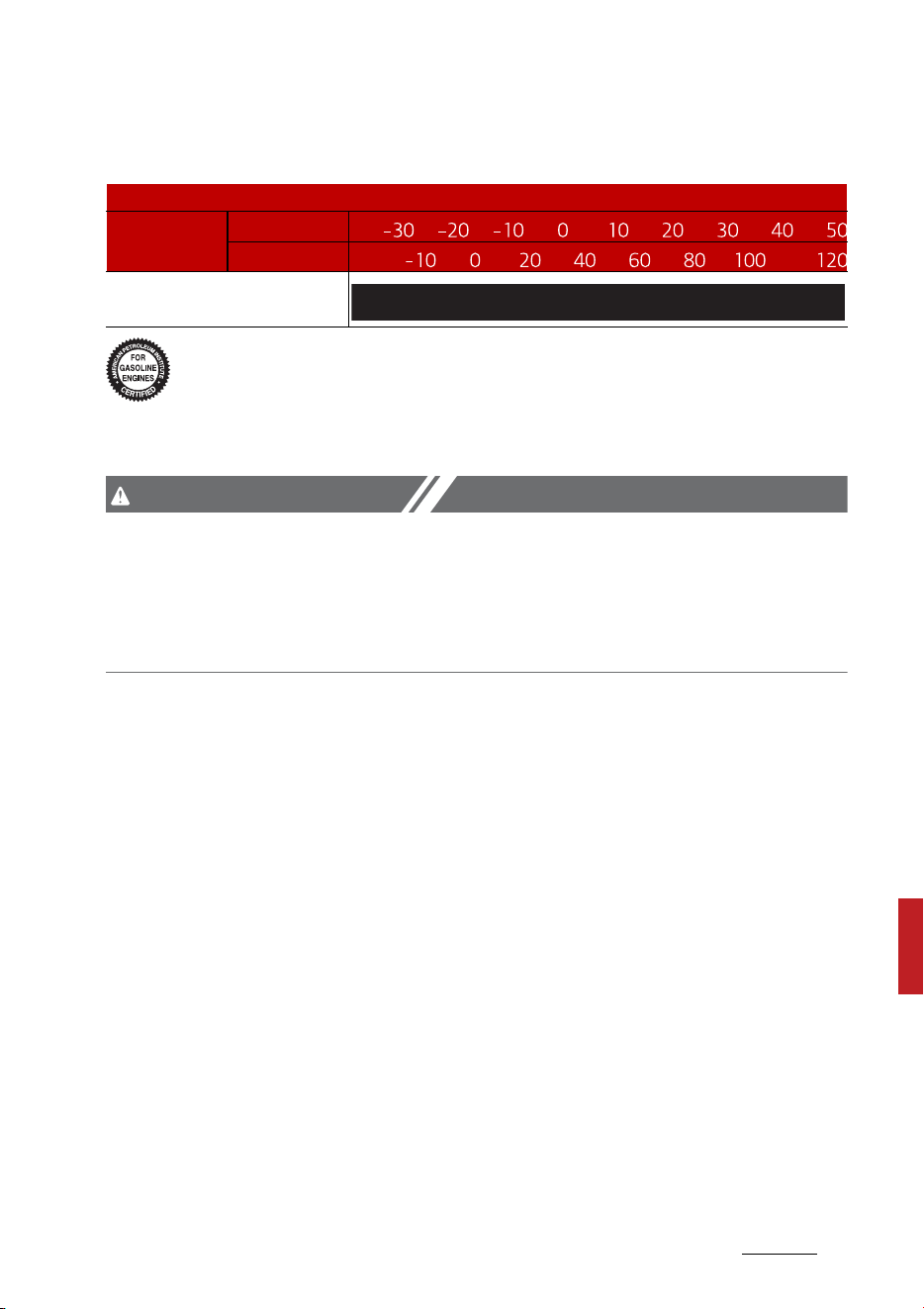
9
9
9
Specifications, Consumer information and
Reporting safety defects
Recommended lubricants and capacities
Recommended SAE viscosity number
An engine oil displaying this American Petroleum Institute (API) Cer
-
tification Mark conforms to the International Lubricant Specification
Advisory Committee (ILSAC). It is recommended to only use engine
oils that uphold this API Certification Mark.
CAUTION
Always be sure to clean the area around any filler plug, drain plug, or dip
-
stick before checking or draining any lubricant. This is especially important
in dusty or sandy areas and when the vehicle is used on unpaved roads.
Cleaning the plug and dipstick areas will prevent dirt and grit from entering
the engine and other mechanisms that could be damaged.
Engine oil viscosity (thickness) has an effect on fuel economy and cold
weather operating (engine start and engine oil flowability). Lower viscosity
engine oils can provide better fuel economy and cold weather performance,
however, higher viscosity engine oils are required for satisfactory lubrication
in hot weather.
Using oils of any viscosity other than those recommended could result in
engine damage.
When choosing an oil, consider the range of temperature your vehicle will be
operated in before the next oil change. Proceed to select the recommended
oil viscosity from the chart.
Temperature Range for SAE Viscosity Numbers
Tempera ture
C
F
Smart stream G1.6 T-GDi HEV/
PHEV
*1
0W-20
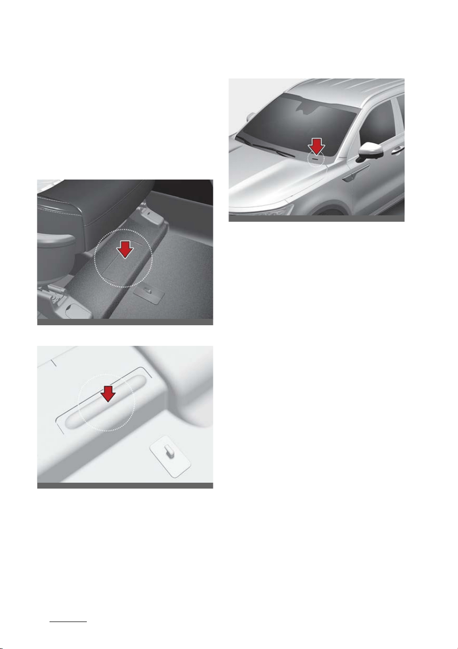
Specifications, Consumer information and
Reporting safety defects
109
Vehicle Identification Number (VIN)
Vehicle Identification Number
(VIN)
The Vehicle Identification Number
(VIN) is the number used in register
-
ing your vehicle and in all legal mat
-
ters pertaining to its ownership, etc.
For hybrid vehicle
For plug-in hybrid vehicle
The number is punched on the floor
under the front passenger's seat. To
check the number, open the cover.
VIN label (if equipped)
The VIN is also on a plate attached
to the top of the dashboard. The
number on the plate can easily be
seen through the windshield from
outside.
OMQ4AH080002
OMQ4PH081001L
OMQ4050266L
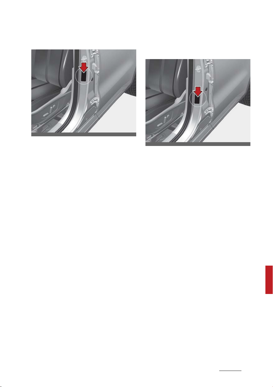
11
9
9
Specifications, Consumer information and
Reporting safety defects
Vehicle certification label
Vehicle certification label
The vehicle certification label
attached on the driver's (or front
passenger's) side center pillar gives
the vehicle identification number
(VIN).
Tire specification and pressure
label
The tires supplied on your new vehi
-
cle are chosen to provide the best
performance for normal driving.
The tire label located on the driver's
side center pillar gives the tire pres
-
sures recommended for your vehi
-
cle.
OMQ4AH080003
OMQ4AH080004
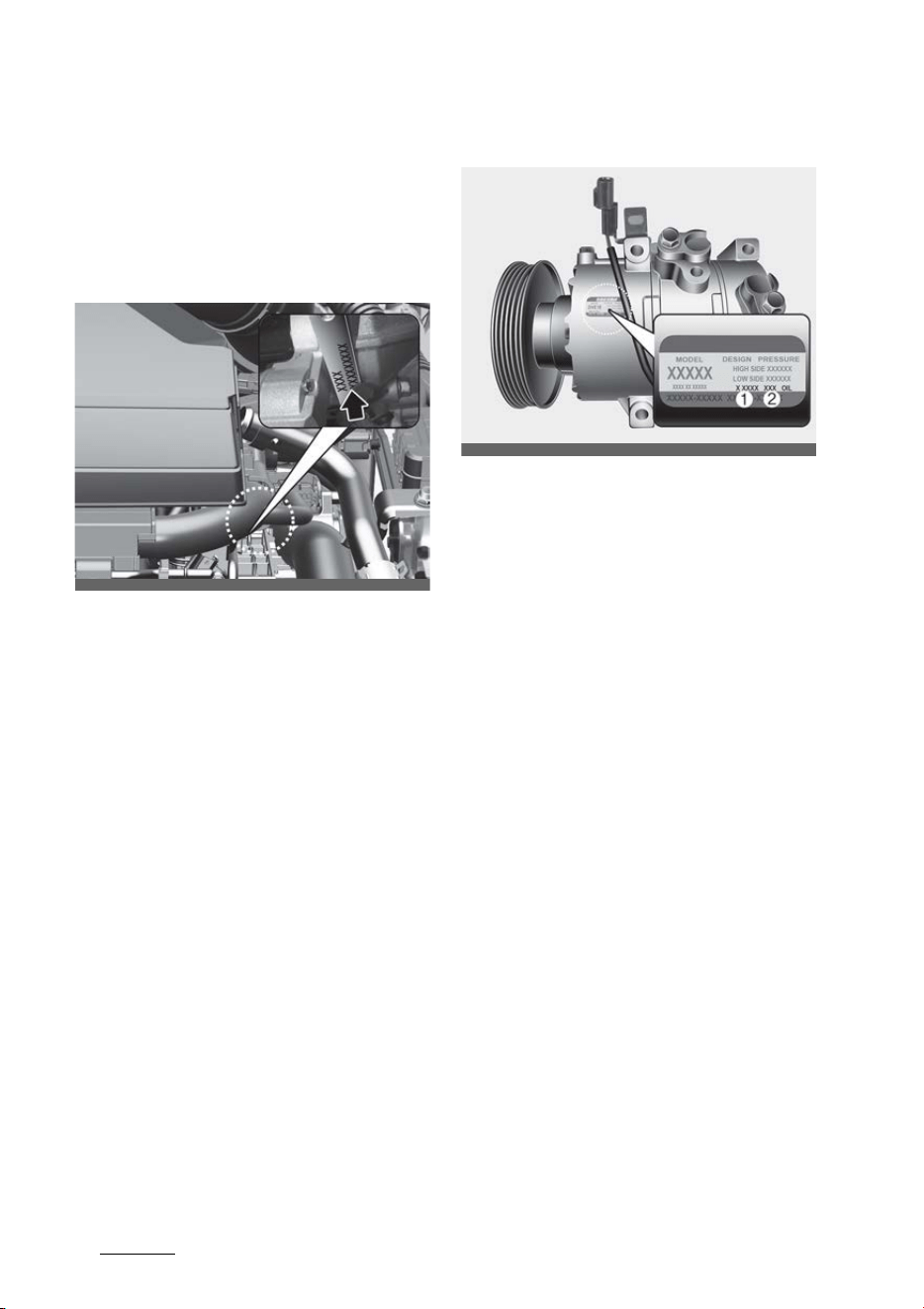
Specifications, Consumer information and
Reporting safety defects
129
Engine number
Engine number
The engine number is stamped on
the engine block as shown in the
drawing.
Smartstream G1.6 T-GDi HEV/PHEV
Air conditioner compressor label
A compressor label informs you the
type of compressor your vehicle is
equipped with such as model, sup
-
plier part number, production num
-
ber, refrigerant (1) and refrigerant
oil (2).
OMQ4080005
OSP2I089010
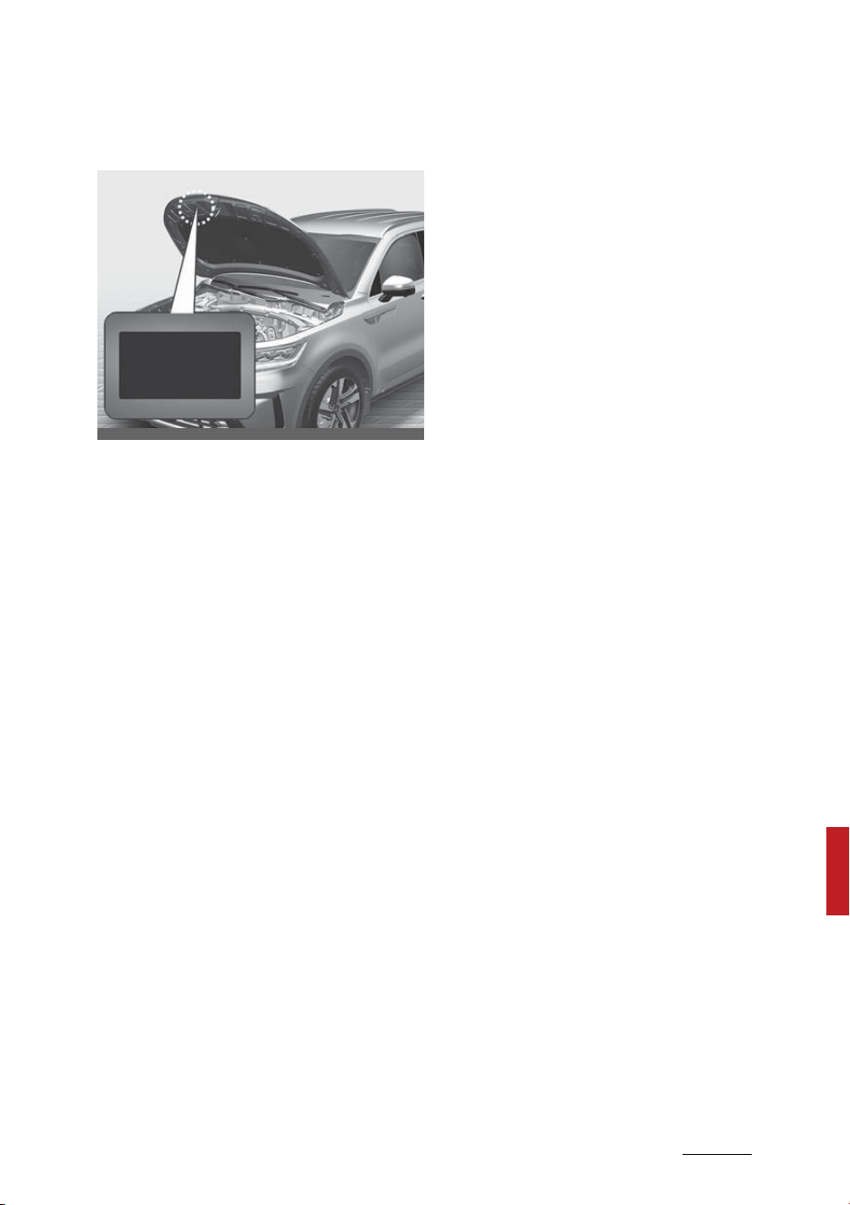
13
9
9
Specifications, Consumer information and
Reporting safety defects
Refrigerant label
Refrigerant label
The refrigerant label is located on
the front body trim.
OMQ4AH080008
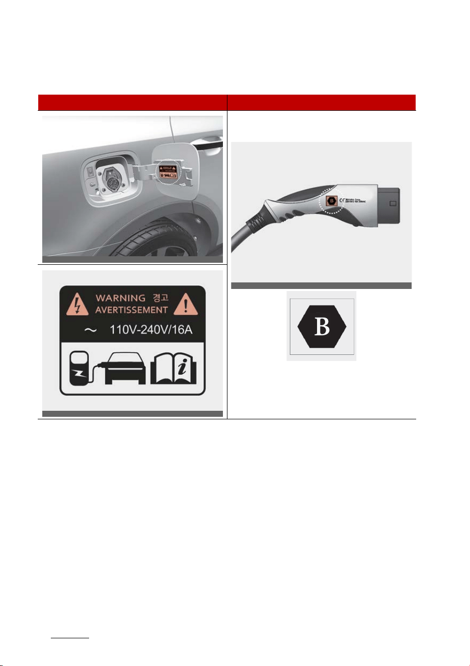
Specifications, Consumer information and
Reporting safety defects
149
How to check the symbol on the charging label
How to check the symbol on the charging label (if equipped)
Precautions for charging AC and Trickle charger (Portable charging cable)
(AC charging)
1. After opening the charging door, check the charging symbol at the bottom
of the warning label.
2. Check the charging connector symbol of the AC and Trickle charger cable.
3. After checking the alphabet letter of the charging symbol, proceed the
charging step.
* Refer to "Electric charging label symbol table" on page 9-15.
4. Risk of failure, fire, injury, etc. expected when using the charging connec
-
tor with unmatched symbol.
Vehicle charging INLET Charging connector OUTLET
<Symbol location and application
example>
OMQ4PH011019L
OMQ4PH091001L
OMQ4091001N
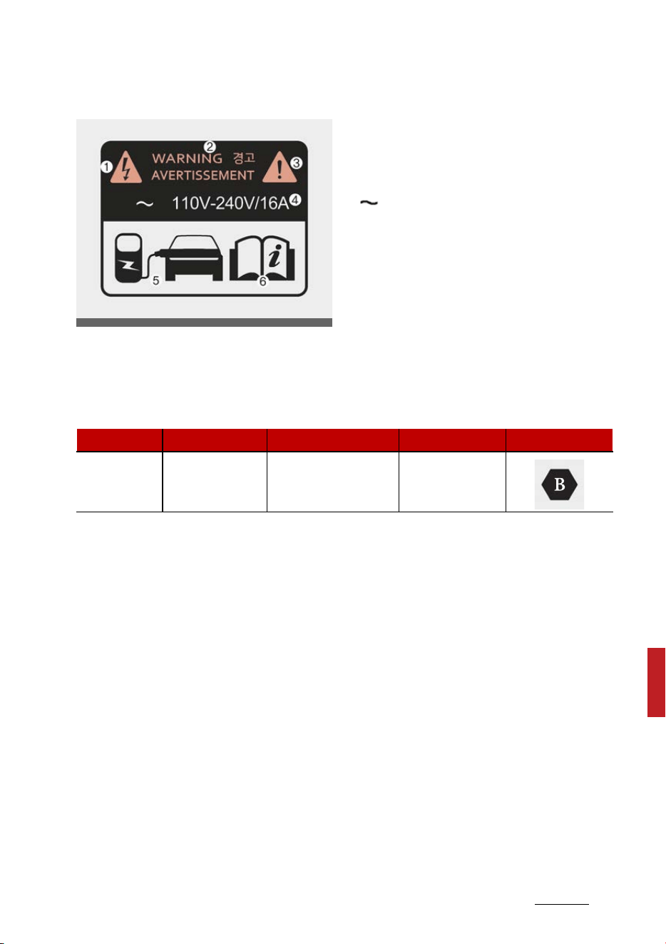
15
9
9
Specifications, Consumer information and
Reporting safety defects
How to check the symbol on the charging label
Electric charging label
The electric charging label is
attached on the charging door.
1 ~ 3: Warning for high voltage
4: Charging voltage and current -
( ) AC single phase.
5: Identifier for charging door.
6: For more details, refer to "How to
check the symbol on the charging
label (if equipped)" on page 9-14.
Electric charging label symbol table
AC and Trickle charger charging
OMQ4091002N
Supply Type Configuration Type of Accessory Voltage range Identifier
AC 5P
Vehicle connector
and vehicle inlet
≤ 250 V RMS

Specifications, Consumer information and
Reporting safety defects
169
Consumer Assistance (U.S. only)
Consumer Assistance (U.S. only)
Roadside Assistance is provided on
all new current model year Kia Vehi
-
cles from the date the vehicle is
delivered to the first retail buyer or
otherwise put into use (inservice
date), whichever is earlier, for a
period of 60 months or 60,000
miles, whichever is earlier, subject to
the terms, conditions and exclusions
set forth in the Kia Warranty and
Consumer Information Manual
applicable to your model year vehi
-
cle.
Kia America, Inc. reserves the right
to limit or deny services or other
benefits to any owner or driver
when, in Kia America, Inc.'s judg
-
ment, the claims and/or service
requests are excessive in frequency
or type of occurrence.
Toll free consumer assistance
is available from 5:00 AM to 6:00 PM
PST, Monday through Friday and is
accessible by dialing 1-800-333-
4Kia (4542).
For more information regarding
assistance available, please refer to
your Kia Warranty & Consumer
Information Manual.
Emergency roadside assistance
is available 24 hours a day, 365 days
a year and is accessible by dialing 1-
800-333-4Kia (4542) or by pressing
the RSA button (when enrolled into
UVO).
Please note that you must provide
your Vehicle Identification Number
(VIN) to verify coverage at the time
of your call. The VIN can be found on
the dash of your vehicle on the
driver's side, on the door jamb of the
driver's door, your vehicle's registra
-
tion or proof of insurance card.
Kia utilizes a network of over 30,000
roadside assistance providers.
Should you accidentally run out of
fuel, require a battery jump, or need
help changing a tire, a Kia Roadside
Assistance Representative will dis
-
patch someone to deliver a small
quantity of gas, change a flat tire
with your inflated spare, or arrange
a battery jump to allow you to pro
-
ceed to your destination. We have
access to a network of over 10,000
locksmiths to help you should you
become locked out of your Kia.
In the event that mechanical diffi
-
culty renders your vehicle undrive
-
able due to a warranty-related
concern, Kia's Roadside Assistance
Representative will arrange to
transport your vehicle to the near
-
est Kia dealer or to an authorized
Kia alternative service location.
Your vehicle must be accessible to
our dispatch transport vehicle, as

17
9
9
Specifications, Consumer information and
Reporting safety defects
Consumer Assistance (U.S. only)
determined by our driver, to receive
this service.
NOTICE
Roadside Assistance benefits are
not available for any Kia vehicle that
has ever been or should have been
issued a "salvage" title or similar
"branded" title under any state's law
or has been declared a "total loss" or
equivalent by a financial institution
or insurance company.
Trip interruption
Trip interruption expense benefits
are provided in the event that a
warranty-related disablement
occurs more than 150 miles from
your home, and the repairs require
more than 24 hours to complete.
Reasonable reimbursement is
included for meals, lodging, or rental
vehicle expenses. Trip interruption
coverage is limited to $100 per day
subject to a three day maximum
limit per incident. You must contact
the Kia Roadside Assistance Center
to obtain pre-authorization of
expenses. Once the Kia Roadside
Assistance Center gives authoriza
-
tion for trip interruption benefits,
they will assist you in making the
necessary arrangements. Insurance
deductibles, expenses, and claims
paid by your insurance company or
other providers are not eligible for
reimbursement.
Fleet vehicles are excluded from
reimbursement under Kia's Trip
Interruption Policy.
Registering your vehicle in a foreign
country
If you plan to register your vehicle in
a foreign country, you should con
-
firm that it conforms to the regula
-
tions in that country. Even if you
successfully register the vehicle in a
foreign country, you may experi
-
ence the following problems and
should therefore consider the possi
-
bility of having to deal with them:
1. The fuel specified for your vehicle
may be unavailable. If other than
the specified fuel is used, it could
cause damage to the engine, the
fuel injection system, and other
fuel-related parts which may not
be covered under your New Vehi
-
cle Emissions Limited Warranty.
2. We must, therefore, clearly state
that when you leave the country
in which you purchased your Kia
new and register it in another
country, problems arising from
the use of fuel other than the
specified fuel are not subject to
manufacturer's warranty.
Because vehicles like yours may
not be marketed in the new coun
-
try of registration, parts, servic
-
ing techniques and tools

Specifications, Consumer information and
Reporting safety defects
189
Electrical Equipment (U.S. only)
necessary to maintain and repair
your vehicle may be unavailable.
Even if vehicles like yours are sold
there, mechanical specifications
required by the government may
vary enough from the country of
purchase to cause additional
problems.
3. There may not be an Authorized
Kia Dealer in the area in which you
plan to register your vehicle. You
may additionally experience diffi
-
culty in obtaining services in a
foreign country for any number
of reasons.
Further, we cannot assume any
responsibility for problems that
result from unsatisfactory service
or lack of service outside of the
United States.
Electrical Equipment (U.S. only)
The electrical system of your vehicle
is designed to perform under all
reasonably expected operating con
-
ditions.
However, before any additional elec
-
trical equipment is installed in your
vehicle, consult an Authorized Kia
Dealer, in order to ensure that you
do not void your warranty.
Certain electrical equipment, or the
way in which it is installed, may
adversely affect the operation of
your vehicle, including such sys
-
tems as the engine control system,
the audio system and the electrical
charging system and thus poten
-
tially void all or part of your war
-
ranty.
We assume no responsibility for any
expense you may incur or for any
malfunction of your vehicle or any
of its components or systems that
may result from the installation of
additional electrical equipment that
is not supplied, or recommended for
installation by, Kia.
Installation of a mobile two-way
radio system
If a mobile two-way radio system is
installed improperly, or if an exces
-
sively powerful type of system is
used, other electronic systems may
be adversely affected. To avoid

19
9
9
Specifications, Consumer information and
Reporting safety defects
Reporting Safety Defects (U.S. only)
damage to your vehicle, consult an
Authorized Kia Dealer concerning
the proper equipment and installa
-
tion.
Kia vehicles are designed and manu
-
factured to meet or exceed all appli
-
cable safety standards.
For your safety, however, we
strongly urge you to read and follow
all directions in this Owner's Manual,
particularly the information under
the headings "NOTICE", "CAUTION"
and "WARNING".
If, after reading this manual, you
have any questions regarding the
operation of your vehicle, safety
issues and defects, please contact
your Kia's toll-free Consumer Assis
-
tance hot line as below:
National Consumer Affairs Manager
Kia America, Inc.
P.O. Box 52410
Irvine, CA 92619-2410
1-800-333-4Kia (4542)
Reporting Safety Defects (U.S.
only)
If you believe that your vehicle has a
defect which could cause a crash or
could cause injury or death, you
should immediately inform the
National Highway Traffic Safety
Administration (NHTSA) in addition
to notifying Kia America, Inc.
If NHTSA receives similar com
-
plaints, it may open an investigation,
and if it finds that a safety defect
exists in a group of vehicles, it may
order a recall and remedy campaign.
However, NHTSA cannot become
involved in individual problems
between you, your dealer, or Kia
America, Inc.
To contact NHTSA, you may call the
Vehicle Safety Hotline toll-free at 1-
888-327-4236 (TTY: 1-800-424-
9153); go to http://www.safer
-
car.gov; download the SaferCar
mobile application; or write to:
Administrator, NHTSA, 1200 New
Jersey Ave. SE., Washington, DC
20590.
You can also obtain other informa
-
tion about motor vehicle safety
from http://www.safercar.gov.

Specifications, Consumer information and
Reporting safety defects
209
Online factory authorized manuals (U.S. only)
Online factory authorized man
-
uals (U.S. only)
The following publications are avail
-
able on www.KiaTechinfo.com.
Service manual
This manual covers maintenance
and recommended procedures for
repair to engine and chassis compo
-
nents. It is written for the Journey
-
man mechanic, but is simple enough
for most mechanically inclined own
-
ers to understand.
Electrical troubleshooting manual
This manual complements the Ser
-
vice Manual by providing in-depth
troubleshooting information for
each electrical circuit in your vehicle.
Owner's manual
This manual describes the overall
features and operating procedures
for the vehicle.

AAbbreviation
Abbreviation

Abbreviation
2A
Abbreviation
ABS
Anti-lock Brake System
ASM
Active Snow Mode
BAS
Brake Assistant System
BCA
Blind-Spot Collision-Avoidance
Assist
BCW
Blind-Spot Collision Warning
BVM
Blind-Spot View Monitor
CC
Cruise Control
CRS
Child Restraint System
DAW
Driver Attention Warning
DBC
Downhill Brake Control
DRL
Daytime Running Light
EBD
Electronic Brake force Distribution
ECM
Electric Chromic Mirror
EPS
Electric Power Steering
ESC
Electronic Stability Control
ESS
Emergency Stop Signal
FCA
Forward Collision-Avoidance
Assist
HAC
Hill-start Assist Control
HBA
High Beam Assist
HDA
Highway Driving Assist
HMSL
High Mounted Stop Lamp
HUD
Head-Up Display
ISLA
Intelligent Speed Limit Assist
LATCH
Lower Anchors and Tether for
Children
LFA
Lane Following Assist
LKA
Lane Keeping Assist
MCB
Multi-Collision Brake
MDPS
Motor Driven Power Steering

3A
Abbreviation
MIL
Malfunction Indicator Lamp
MSLA
Manual Speed Limit Assist
NSCC
Navigation-based Smart Cruise
Control
ODS
Occupant Detection System
PCA
Reverse Parking Collision-Avoid
-
ance Assist
PDW
Reverse Parking Distance Warning
RCCA
Rear Cross-Traffic Collision-
Avoidance Assist
RCCW
Rear Cross-Traffic Collision Warn
-
ing
RVM
Rear View Monitor
SBW
Shift-By-Wire
SCC
Smart Cruise Control
SEA
Safe Exit Assist
SEW
Safe Exit Warning
SRS
Supplemental Restraint System
SRSCM
SRS Control Module
SVM
Surround View Monitor
TBT
Turn By Turn
TCS
Traction Control System
TIN
Tire Identification Number
TPMS
Tire Pressure Monitoring System
VESS
Virtual Engine Sound System
Number
VIN
Vehicle Identification Number
VSM
Vehicle Stability Management


IIndex
Index

2I
Index
A
AC charge 1-10
AC charging connector lock 1-6
AC inverter 5-185
accumulated driving information
mode
5-101
adjusting instrument cluster
illumination
5-82
adjusting the height of shoulder
belt
4-28
adjusting the outside rear view
mirror
5-76
air bag 4-46
air bag collision sensors 4-66
air bag warning labels
4-73
curtain air bag 4-64
driver䳓s and passenger䳓s
front air bag 4-60
occupant detection system
(ODS)
4-53
side air bag 4-63
SRS components and functions 4-50
air bag collision sensors 4-66
air bag warning and indicator 4-49
air bag warning labels 4-73
air cleaner filter 8-29
air conditioning
refrigerant label
5-159
air ventilation seat 5-181
all wheel drive (AWD) system 6-22
ambient light 5-177
antenna 5-197
anti-lock brake system (ABS) 6-42
appearance care 8-79
armrest 4-23
audio system 5-197
antenna 5-197
radio
5-199
USB port 5-198
auto hold 6-39
automatic climate control
system
5-161
heating and air conditioning
automatically
5-163
heating and air conditioning
manually
5-165
automatic transmission
LCD display messages 6-17
automatic transmission
(dial SBW)
6-14
operation
6-14
automatic turn off function 5-152
AWD
AWD mode 6-23
safe operation
6-25
B
battery 8-35
battery saver function 5-140
before driving 6-7
blind-spot collision-avoidance
assist (BCA)
6-95
blind-spot view monitor
(BVM)
6-134
brake assist system (BAS) 6-51
brake fluid 8-26
brake system 6-32
anti-lock brake system (ABS)
6-42
auto hold 6-39
brake assist system (BAS)
6-51
downhill brake control (DBC) 6-47
electronic parking brake (EPB) 6-34
electronic stability control (ESC)
system
6-44
good braking practices 6-52
hill-start assist control (HAC)
6-49
power brakes
6-32
trailer stability assist (TSA)
6-51
vehicle stability management
(VSM) system 6-49

3I
C
care of seat belts 4-35
cargo security screen 5-193
center console storage 5-176
changing plug-in hybrid mode
(plug-in hybrid vehicle)
1-22
charging Information 1-4
charging precautions 1-8
charging status 1-5
charging the plug-in hybrid
vehicle
1-4
AC charge
1-10
AC charging connector lock
1-6
charging Information
1-4
charging precautions
1-8
charging status
1-5
charging time 1-4
charging type 1-4
how to disconnect charging
connector in emergency
1-20
scheduled charging 1-6
trickle charger (portable charging
cable) 1-13
charging time 1-4
charging type 1-4
child restraint system (CRS) 4-36
installing a CRS 4-39
selecting a CRS
4-37
climate control air filter 8-30
climate control system 5-156
climate control air filter
5-158
closing the hood 5-47
closing the liftgate 5-30
closing the power liftgate 5-34
coat hook 5-190
components of the
hybrid/plug-in hybrid vehicle
1-40
plug-in hybrid vehicle
components
1-40
consumer assistance 9-16
coolant 8-22
cruise control (CC) 6-136
cup holder 5-178
curtain air bag 4-64
D
day/night rear view mirror 5-64
daytime running light (DRL) 5-141
defogging (windshield) 5-172
defroster 5-174
defrosting (windshield) 5-172
distance to empty 5-87
door locks 5-17
child-protector rear door lock
5-22
door lock/unlock features
5-21
electronic child safety
lock system
5-22
from inside the vehicle
5-19
in case of an emergency 5-23
rear occupant alert
(ROA) system 5-24
with the mechanical key
5-18
with the smart key 5-17
door lock/unlock features 5-21
downhill brake control (DBC) 6-47
drive info display 5-101
drive mode 6-55
drive mode integrated control
system
6-55
drive mode
6-55
smart shift on trip computer 6-58
driver attention warning
(DAW)
6-127
driver position memory
system
5-26
easy access function
5-28
driver䳓s and passenger䳓s
front air bag
4-60
driving assist mode 5-92
driving at night 6-218
driving in flooded areas 6-219
driving in the rain 6-218

4I
driving the plug-in hybrid vehicle
changing plug-in hybrid mode
(plug-in hybrid vehicle)
1-22
E
easy access function 5-28
economical operation 6-208
electric chromic mirror (ECM)
with HomeLink system
5-65
electrical equipment 9-18
electronic child safety
lock system
5-22
electronic chromic mirror
(ECM)
5-65
electronic parking brake
(EPB)
6-34
applying the parking brake
6-34
EPB malfunction 6-38
EPB warning messages 6-36
releasing the parking brake
6-35
electronic stability control
(ESC) system
6-44
emergency 7-2
emergency liftgate safety
release
5-30
emission control system 8-87
engine compartment fuse
replacement
8-54
engine oil 8-19
engine overheats 7-8
engine start/stop button 6-9
starting the engine
6-11
engine start/stop button
position
6-9
explanation of scheduled
maintenance items
8-16
exterior features 5-196
roof rack
5-196
F
fastening the seat belt 4-27
floor mat anchor(s) 5-192
folding the outside rear view
mirror
5-77
forward collision-avoidance
assist (FCA) - front view
camera only
6-60
forward collision-avoidance a
ssist (FCA)
- sensor fusion type
6-73
forward/reverse parking
distance warning (PDW)
5-134
front fog light 5-144
front seat adjustment
for manual seat
4-8
front seat adjustment
for power seat
4-10
front seat headrest 4-18
fuel economy 5-101
fuel filler door 5-48
closing the fuel filler door
5-51
opening the fuel filler door 5-48
fuel gauge 5-85
fuel requirements 2-2
full LCD cluster 5-81
fuses 8-51
engine compartment fuse
replacement
8-54
inner panel fuse replacement 8-53
G
gauges 5-83
distance to empty 5-87
fuel gauge
5-85
odometer 5-86
outside temperature gauge 5-88
plug-in hybrid mode
indicator
1-26, 5-85
power gauge 5-83

5I
SOC gauge 5-84
speedometer
5-83
glove box 5-176
glove box lamp 5-155
good braking practices 6-52
H
hazardous driving
conditions
6-215
headlamp delay function 5-140
headrest
front seat headrest 4-18
rear seat headrest
4-21
head-up display (HUD) 5-122
heated steering wheel 5-62
heating and air conditioning
automatically
5-163
heating and air conditioning
manually
5-165
HEV (hybrid electric vehicle)
system
1-3
hev powertrain 2-7
high beam assist (HBA) 5-144
highway driving 6-219
highway driving assist
(HDA)
6-167
hill-start assist control
(HAC)
6-49
hood 5-47
closing the hood
5-47
opening the hood 5-47
horn 5-63
hybrid starter & generator
(HSG) belt
8-26
hybrid system overview 1-2
hydroplaning 6-219
I
if you have a flat tire
(with spare tire)
7-15
immobilizer system 5-13
Important safety precautions 4-3
in case of an emergency
while driving
7-3
indicator lights 5-118
information mode 5-92
infotainment system 5-197
audio system
5-197
inner panel fuse replacement 8-53
inside rear view mirror 5-64
installing a CRS 4-39
instrument cluster 5-80
adjusting instrument cluster
illumination
5-82
full LCD cluster
5-81
gauges
5-83
plug-in hybrid mode
indicator 1-26, 5-85
transmission shift indicator
5-88
intelligent speed limit assist
(ISLA)
6-122
interior features 5-177
AC inverter
5-185
air ventilation seat 5-181
ambient light 5-177
cargo security screen 5-193
coat hook
5-190
cup holder 5-178
floor mat anchor(s) 5-192
power outlet 5-184
seat warmer
5-179
side curtain 5-191
sun visor 5-182
USB charger
5-183
wireless smart phone charging
system 5-187
interior light 5-152
automatic turn off function 5-152
glove box lamp 5-155
luggage room lamp
5-154
map lamp 5-153
room lamp 5-154
vanity mirror lamp 5-155

6I
J
jump-starting 7-5
K
keys 5-7
battery replacement
5-11
smart key 5-7
L
lane following assist (LFA) 6-163
lane keeping assist (LKA) 6-89
LCD display 5-90
LCD display modes
5-91
LCD display messages 5-104
LCD display modes 5-91
LCD displays 5-100
LCD display messages
5-104
service mode 5-103
trip information
(trip computer)
5-100
liftgate 5-29
closing the liftgate
5-30
emergency liftgate safety
release 5-30
opening the liftgate
5-29
power liftgate 5-32
light bulbs 8-65
light bulb position (front)
8-66
light bulb position (rear) 8-67
light bulb position (side) 8-68
lighting 5-140
battery saver function
5-140
daytime running light (DRL) 5-141
front fog light 5-144
headlamp delay function 5-140
high beam assist (HBA)
5-144
lighting control 5-141
operating high beam 5-142
operating turn signals 5-143
lighting control 5-141
auto light
5-142
head light (low beam)
5-142
luggage board 5-194
luggage net holder 5-192
luggage room lamp 5-154
luggage side tray 5-195
luggage tray 5-195
M
maintenance services 8-6
manual speed limit assist
(MSLA)
6-119
map lamp 5-153
master warning mode 5-93
mechanical key 5-9
mirrors 5-64
adjusting the outside rear
view mirror
5-76
day/night rear view mirror 5-64
electric chromic mirror (ECM)
with HomeLink system
5-65
electronic chromic mirror (ECM) 5-65
folding the outside rear view
mirror
5-77
inside rear view mirror 5-64
outside rear view mirror 5-76
reverse parking aid function 5-78
N
navigation-based smart cruise
control (NSCC)
6-156
O
occupant detection system
(ODS)
4-53
odometer 5-86
one-touch lane change
function
5-143

7I
online factory authorized
manuals
9-20
opening the hood 5-47
opening the liftgate 5-29
opening the power liftgate 5-33
operating high beam 5-142
operating rear window wiper
and washer switch
5-150
operating turn signals 5-143
operating windshield
washers
5-149
outside rear view mirror 5-76
outside temperature gauge 5-88
overloading 6-238
owner maintenance 8-8
P
paddle shifter 6-21
panoramic sunroof 5-55
power sunshade
5-56
resetting the sunroof 5-58
PHEV (plug-in hybrid electric
vehicle) system
1-2
plug-in hybrid mode
indicator
1-26, 5-85
plug-in hybrid vehicle
components
1-40
power brakes 6-32
power gauge 5-83
power liftgate 5-32
closing the liftgate
5-34
opening the liftgate 5-33
speed adjustment 5-36
power liftgate speed
adjustment
5-36
power outlet 5-184
power sunshade 5-56
power window lock button 5-45
pre-tensioner seat belt 4-31
push-starting 7-7
R
rear cross-traffic collision-
avoidance assist (RCCA)
6-174
rear occupant alert (ROA)
system
5-24
rear seat adjustment 4-12
rear seat headrest 4-21
rear view monitor (RVM) 5-124
reducing the risk of
a rollover
6-215
releasing the seat belt 4-28
remote smart parking assist
(RSPA)
6-192
replacing rear wiper blades 8-34
reporting safety defects 9-19
reverse parking aid function 5-78
reverse parking collision-
avoidance assist (PCA)
6-185
reverse parking distance
warning (PDW)
5-130
risk of burns when parking or
stopping vehicle
2-5
rocking the vehicle 6-217
roof rack 5-196
room lamp 5-154
S
safe exit assist (SEA) 6-112
safe exit warning (SEW) 6-108
scheduled charging 1-6
scheduled maintenance
service
8-10
normal maintenance schedule
8-12
seat 4-5
armrest
4-23
feature of seat leather 4-8
front seat adjustment
for manual seat
4-8
front seat adjustment
for power seat 4-10

8I
rear seat adjustment 4-12
seatback pocket
4-23
small pocket 4-24
seat belt precautions 4-33
seat belt restraint system 4-24
seat belts 4-24
child restraint system (CRS)
4-36
seat warmer 5-179
seatback pocket 4-23
selecting a CRS 4-37
service interlock connector 1-47
service mode 5-103
side air bag 4-63
side curtain 5-191
small pocket 4-24
smart cruise control (SCC) 6-139
smart key 5-7
mechanical key
5-9
smart liftgate with auto
open
5-38
smooth cornering 6-217
snow tires 6-222
SOC gauge 5-84
special driving conditions 6-215
specifications
air conditioner compressor label 9-12
air conditioning system
9-4
bulb wattage 9-5
dimensions 9-2
engine 9-2
engine number
9-12
gross vehicle weight 9-3
lubricants and capacities 9-8
luggage volume 9-3
refrigerant label
9-13
tire specification and pressure
label 9-11
tires and wheels 9-6
vehicle certification label
9-11
vehicle identification number
(VIN) 9-10
speedometer 5-83
SRS components and
functions
4-50
starting the engine 6-11
Starting and stopping the engine
for turbocharger intercooler
6-13
starting the engine 6-13
starting the engine with
smart key
6-11
steering wheel 5-60
electric power steering (EPS)
5-60
heated steering wheel
5-62
horn
5-63
tilt & telescopic steering wheel
5-61
storage compartment 5-176
center console storage
5-176
glove box
5-176
luggage board
5-194
luggage net holder 5-192
luggage side tray 5-195
luggage tray 5-195
stowing the rear seat belt 4-30
sun visor 5-182
supplemental restraint
system (SRS) care
4-70
surround view monitor
(SVM)
5-126
T
theft-alarm system 5-14
tilt & telescopic steering
wheel
5-61
tire chains 6-221
tire pressure monitoring
system (TPMS)
7-9
tires and wheels 8-38
all season tires 8-48
checking tire inflation pressure 8-39
radial-ply tires
8-50
snow tires 8-49
summer tires 8-49
tire chains 8-49
tire maintenance
8-42

9I
tire replacement 8-41
tire rotation
8-40
tire sidewall labeling 8-43
tire terminology and definitions
8-46
tire traction
8-42
wheel alignment and tire
balance
8-41
wheel replacement
8-42
towing 7-26
without wheel dollies
7-26
trailer stability assist (TSA) 6-51
trailer towing 6-224
driving with a trailer
6-227
hitches
6-226
maintenance
6-230
safety chains
6-226
trailer brakes
6-226
transmission shift indicator 5-88
trickle charger (portable
charging cable)
1-13
trip information (Trip computer)
energy flow 5-103
range 5-103
trip information
(trip computer)
5-100
accumulated driving information
mode 5-101
drive info display
5-101
fuel economy 5-101
trip modes 5-100
trip modes 5-100
turn by turn (TBT) mode 5-92
U
USB charger 5-183
USB port 5-198
user settings mode 5-93
V
vanity mirror lamp 5-155
vehicle auto shut-off system 6-53
vehicle break-in process 2-5
vehicle data collection and
event data recorders
2-6
vehicle handling instructions 2-6
vehicle identification number
(VIN)
9-10
vehicle load limit 6-233
vehicle modifications 2-4
vehicle stability management
(VSM) system
6-49
vehicle weight 6-237
virtual engine sound system
(VESS)
1-24
W
warning and indicator lights 5-111
warning lights 5-111
washer fluid 8-28
welcome system 5-151
what do do in an emergency
emergency starting 7-5
engine overheats 7-8
if the engine will not start 7-4
if you have a flat tire
(with spare tire)
7-15
road warning 7-2
when the hybrid vehicle
shuts off
1-48
window opening and
closing
5-43
windows 5-42
power window lock button
5-45
window opening and closing 5-43
windshield defrosting and
defogging
5-172
defogging logic 5-175
winter driving 6-220
wiper blades 8-32
wipers and washers 5-147
auto control 5-148

wireless smart phone
charging system
5-187