Installation Guide
MRCHDDVRBR
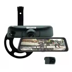
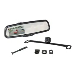
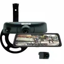
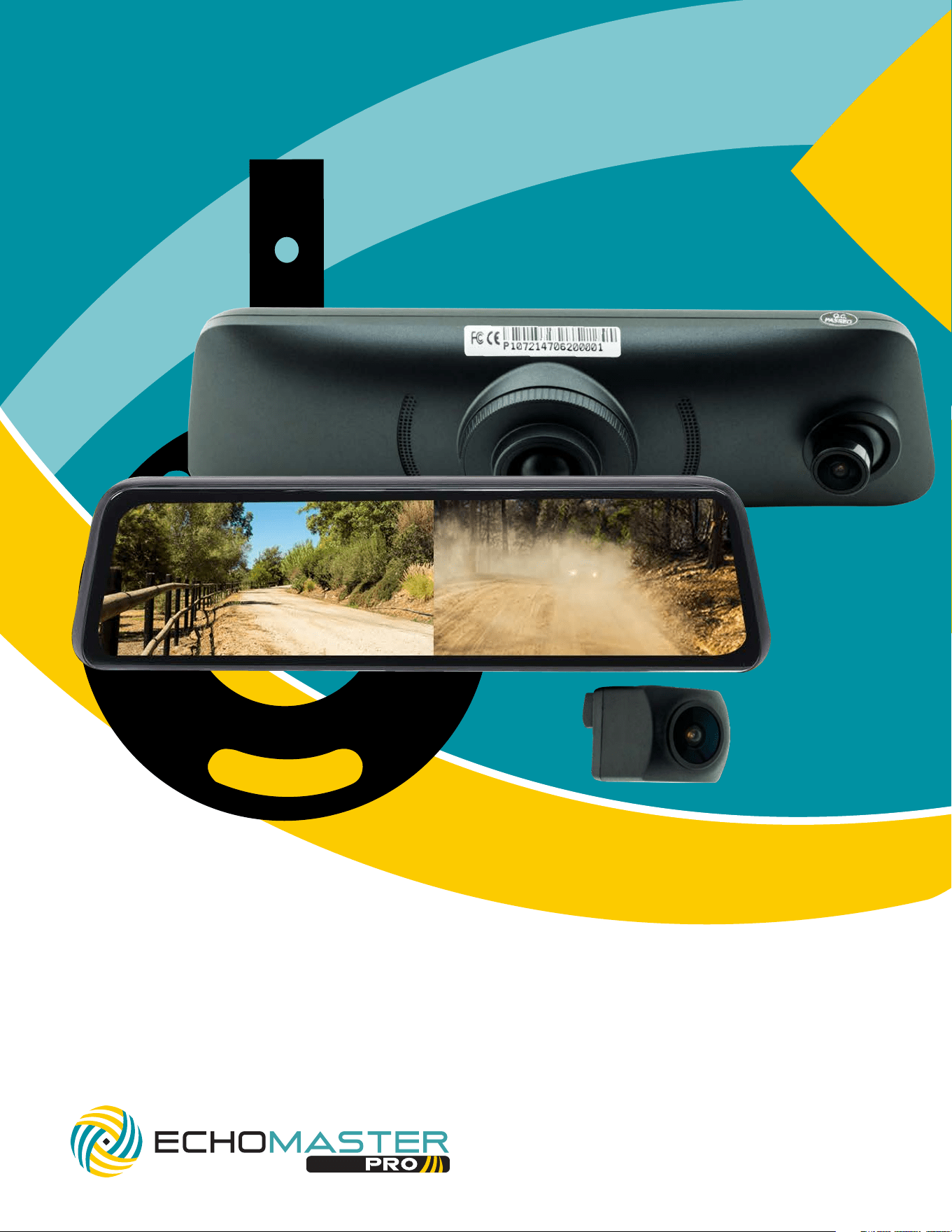
FULL DISPLAY REAR-VIEW MIRROR REPLACEMENT KIT WITH DVR & HD CAMERA
VEHICLE SPECIFIC SPARE TIRE MOUNT & HARDWARE
CLEAR-VIEW
2021-2022 Ford Full Size Bronco
2
Installation Guide
2
tel - 1-800-477-2267
email - support@echomaster.com
Please read and follow the instructions carefully. To emphasize special information, the symbol and the words Warn-
ing, Caution and Note have special meanings. Pay special attention to messages highlighted by these signal words.
ese instructions are designed as a guide to help make the installation of this product successful. Always use caution and
ask for assistance if you are not sure how to proceed.
AAMP Global & EchoMaster are not responsible for any damage that may occur during installation
or any changes to the vehicle interior.
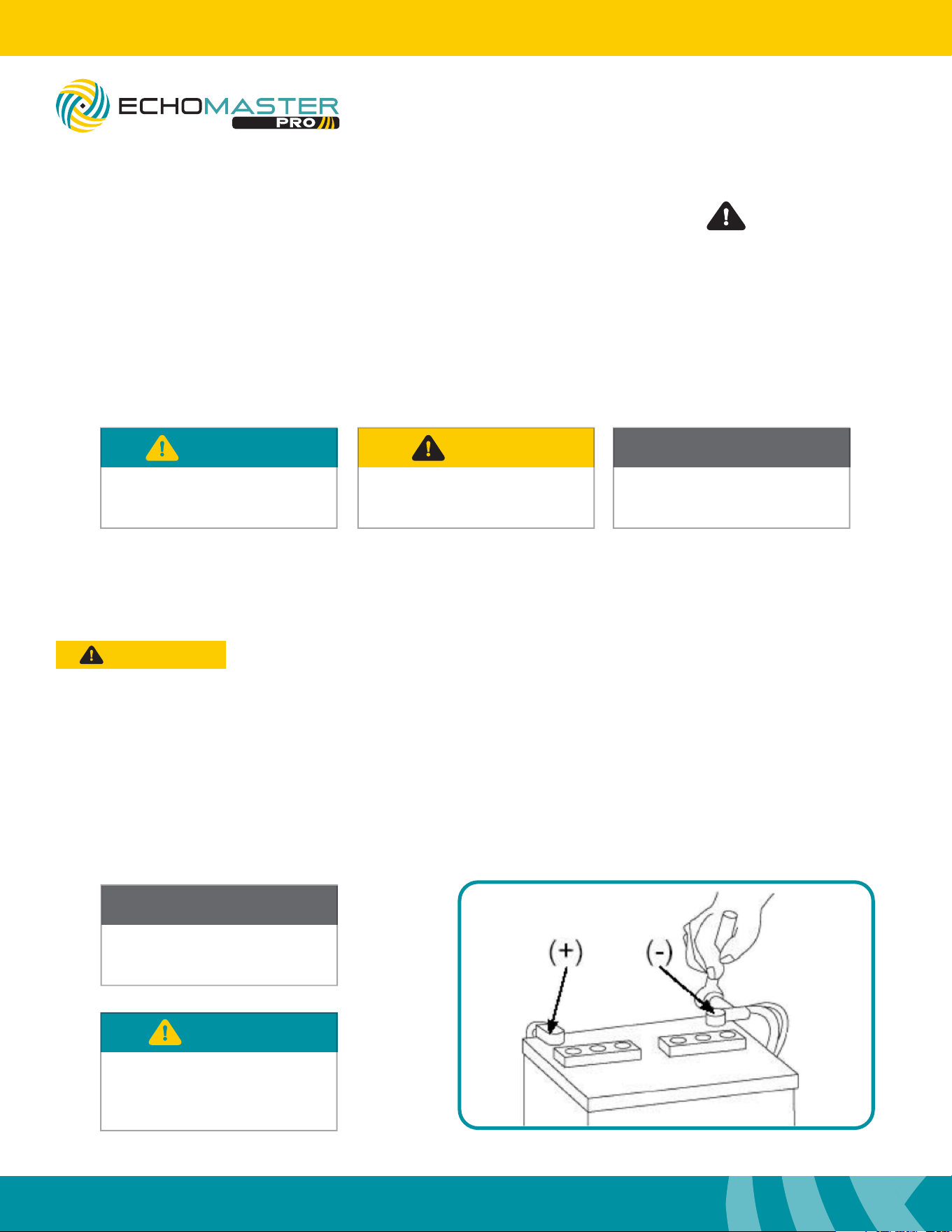
Important
WARNING
Indicates a potential hazard
that could result in a death
or serious injury
CAUTION
Indicates a potential hazard
that could result in vehicle
damage
NOTE
Indicates special information to make
installation easier or instructions clearer.
NOTE
Consult Vehicle owners guide
before disconnecting negative
battery cable
WARNING
DO NOT TOUCH the positive
terminal with any tool when
removing the negative battery cable
Vehicle Preparation & Protection
Consult your vehicle owner’s manual to disconnect the battery. Do not disconnect ANY airbag connectors or indicators.
Doing so may result in activating a diagnostic code. ese codes will require the dealer to perform the reset procedure
which may incur a reset fee. If you are unsure of any vehicle trim removal process consult the OEM service manual.
Removing vehicle trim panels in extreme hot and/or cold climate could result in damage. Use care when
removing all vehicle trims. Using painter’s blue tape on the vehicle trim panels can help limit any scratches and/or marring.
Use a nylon trim panel removal tool whenever possible.
CAUTION
MRCHDDVRBR
3
Installation Guide
3
tel - 1-800-477-2267
email - support@echomaster.com
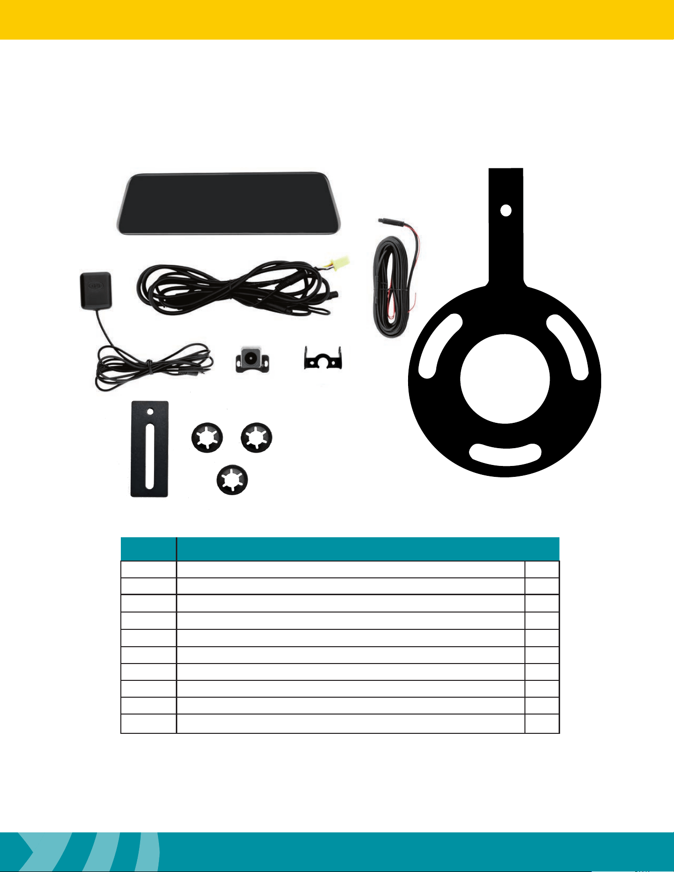
What’s in the box
Image Description Qty
1
Mirror Display / Front Dash Camera 1
2
Display Power / Video Cable 1
3
Camera Extension Cable 1
4
Spare Tire Mounting Bracket 1
5
GPS Antenna 1
6
Rear Camera 1
7
Camera Bracket (PMRC-BRKT) 1
8
Riser Plate 1
9
Push Nuts 3
1
2
3
4
5
6
7
8
9
NOTE: e kit consists of two boxes (MRCHDDVR2 / JP4MOUNTBR.
ere are additional parts included that will not be used.

4
Installation Guide
4
tel - 1-800-477-2267
email - support@echomaster.com
Illustrations are typical and may not match exact vehicle detail
Recommended Tools
Installation Notes
Lug Wrench
Plastic Trim Tool
7mm Socket
8mm Socket
10mm Socket
Ratchet
Socket Extension
#1 Straight Screwdriver
#1 Phillips Screwdriver
#2 Phillips Screwdriver
Diagonal Cutters
Wire Crimpers
Electrical Tape
Wire Feeder
Allen Wrench Set
Hammer
11/16 ” (17mm) Deep Socket
Small Pick Tool
Zip Ties
Utility Knife
Torx T-20, 30
Read this installation guide thoroughly before disassembling vehicle or making wire connections. Installation
of this product requires technical skill, experience, and specialized tools. If unsure,it is recommended to have it
professionally installed by an authorized EchoMaster Dealer.
Questions?
Reach out to our Technical Support Team:
Phone: 727-592-5991
Email: support@aampglobal.com
Chat: EchoMaster.com
5
Installation Guide
5
tel - 1-800-477-2267
email - support@echomaster.com
Illustrations are typical and may not match exact vehicle detail
MRCHDDVRBR
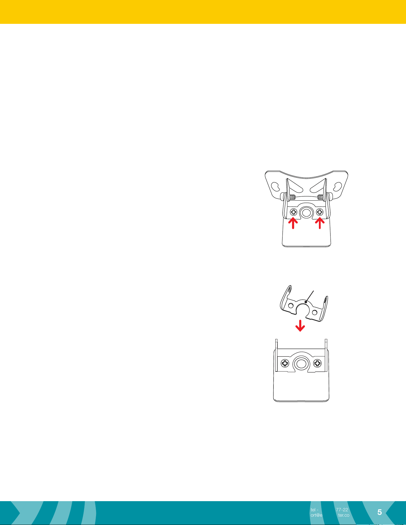
Rear Camera Bracket
e MRCHDDVR2 Rear Camera comes with a “universal” bracket attached. For all Bronco installations,
the universal bracket will need to be removed and the New Camera Bracket from the JP4MOUNTBR will need
to be installed by following the steps below.
Step 1
Using a #1 Phillips screw driver, remove the two screws
securing the universal bracket from the back of the camera and
remove.
Step 2
Attach the New Camera Bracket using the same screws removed in
Step 1.
New Camera Bracket
(PMRC-BRKT)
6
Installation Guide
6
tel - 1-800-477-2267
email - support@echomaster.com
Illustrations are typical and may not match exact vehicle detail
Spare Tire Camera Mount
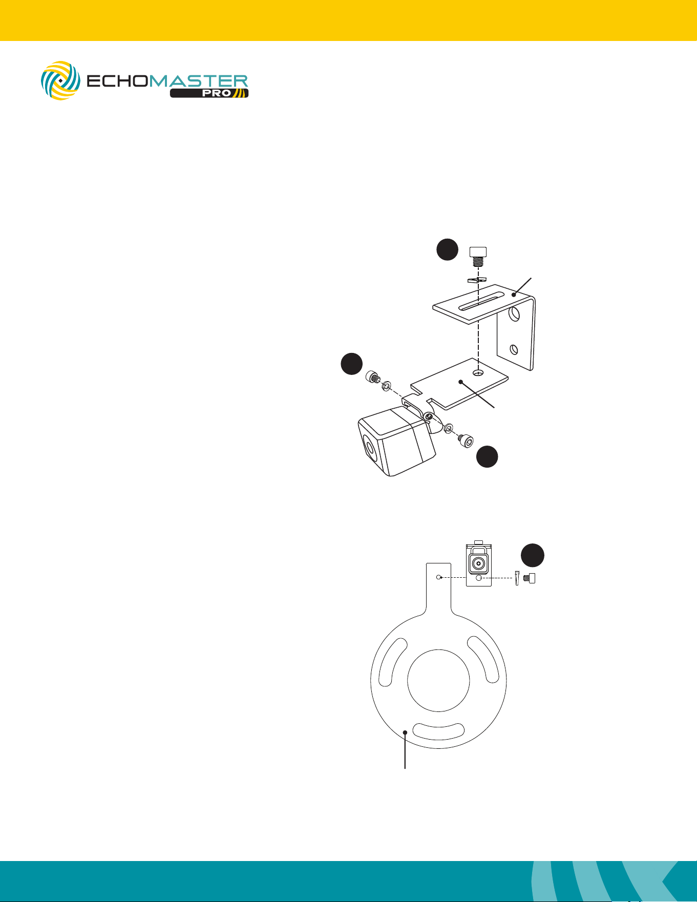
Using the JP4MOUNTBR kit, attach the camera and assemble the mounting bracket as shown.
Assembly
2
1
1
3A
Step 1
Using two M3 x .50 screws and lock wash-
ers, attach the camera to the Camera
Mounting Plate.
Step 2
Using a M6 x 1 screw and lock washer,
attach the Camera Mounting Plate to the
Right Angle Bracket as shown.
Step 3A
For most applications with stock/standard
wheels, attach the camera bracket assembly to
the Wheel Bracket using a M6 x 1 screw and lock
washer.
For applications with larger wheels and/or
o-center wheel openings,
see step 3B.
Wheel Bracket
Camera
Mounting Plate
Right Angle
Bracket
7
Installation Guide
7
tel - 1-800-477-2267
email - support@echomaster.com
Illustrations are typical and may not match exact vehicle detail
MRCHDDVRBR
Assembly
Assembly
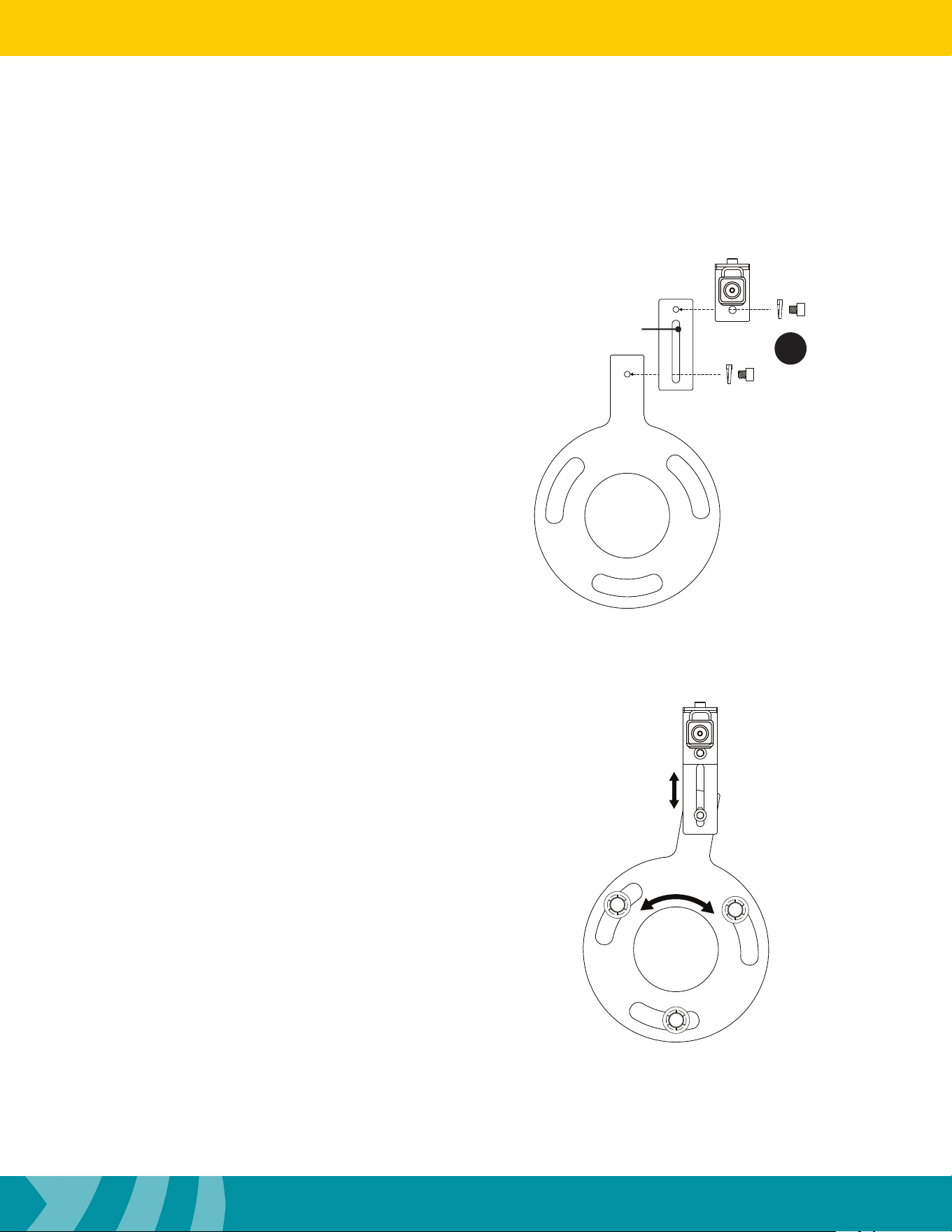
3B
Step 3B
For larger wheels, attach the Riser Plate to the
Wheel Bracket and attach the camera assembly
to the Riser plate using M6 x 1 screws and lock
washers.
When using the riser plate, the camera height,
angle and rotation can be adjusted to match the
wheel.
Riser Plate
Spare Tire Camera Mount (cont)
8
Installation Guide
8
tel - 1-800-477-2267
email - support@echomaster.com
Illustrations are typical and may not match exact vehicle detail
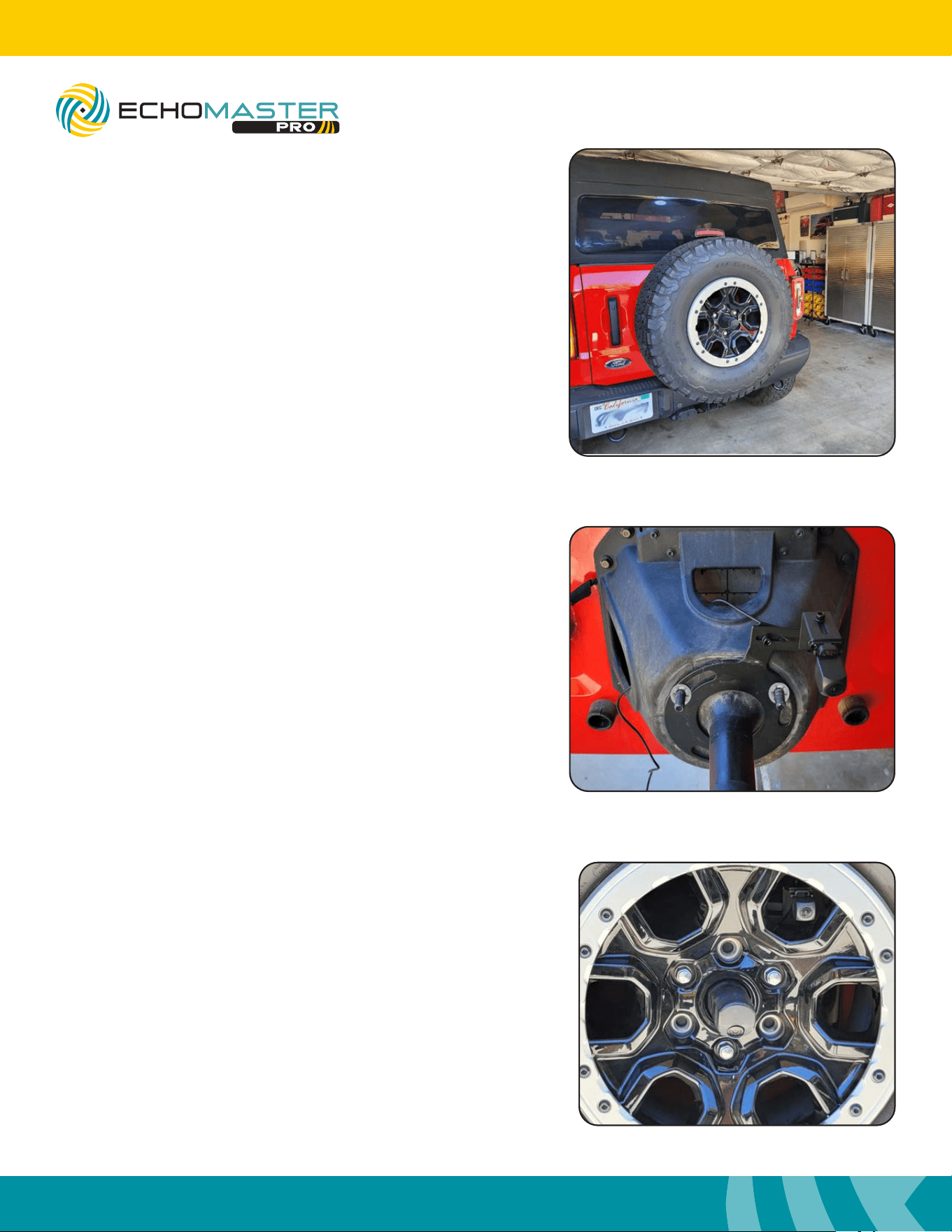
Step 1
Remove the spare tire o of the tire carrier using a 19mm socket,
or factory tire iron. Place the spare tire on the ground face down.
Place the bracket on the back of the spare tire and align camera to t
through a usable opening closest to center as possible.
Mounting the Rear Camera
Step 2
Place the Spare Tire Mounting Bracket and camera assembly on the
wheel studs and secure with the three push nut retainers included in
the JP4MOUNTBR.
e push nut retainers are installed using a 11/16 ”
(17mm) deep socket and a hammer.
Step 3
Temporarily install the spare tire. Conrm a usable opening in the
wheel is located at or close to center. is may require removing
and rotating the wheel until a usable opening is located. If using the
Riser Plate, the camera can be adjusted up and down.
Remove the spare tire. Tighten all camera mount hardware.
9
Installation Guide
9
tel - 1-800-477-2267
email - support@echomaster.com
Illustrations are typical and may not match exact vehicle detail
MRCHDDVRBR
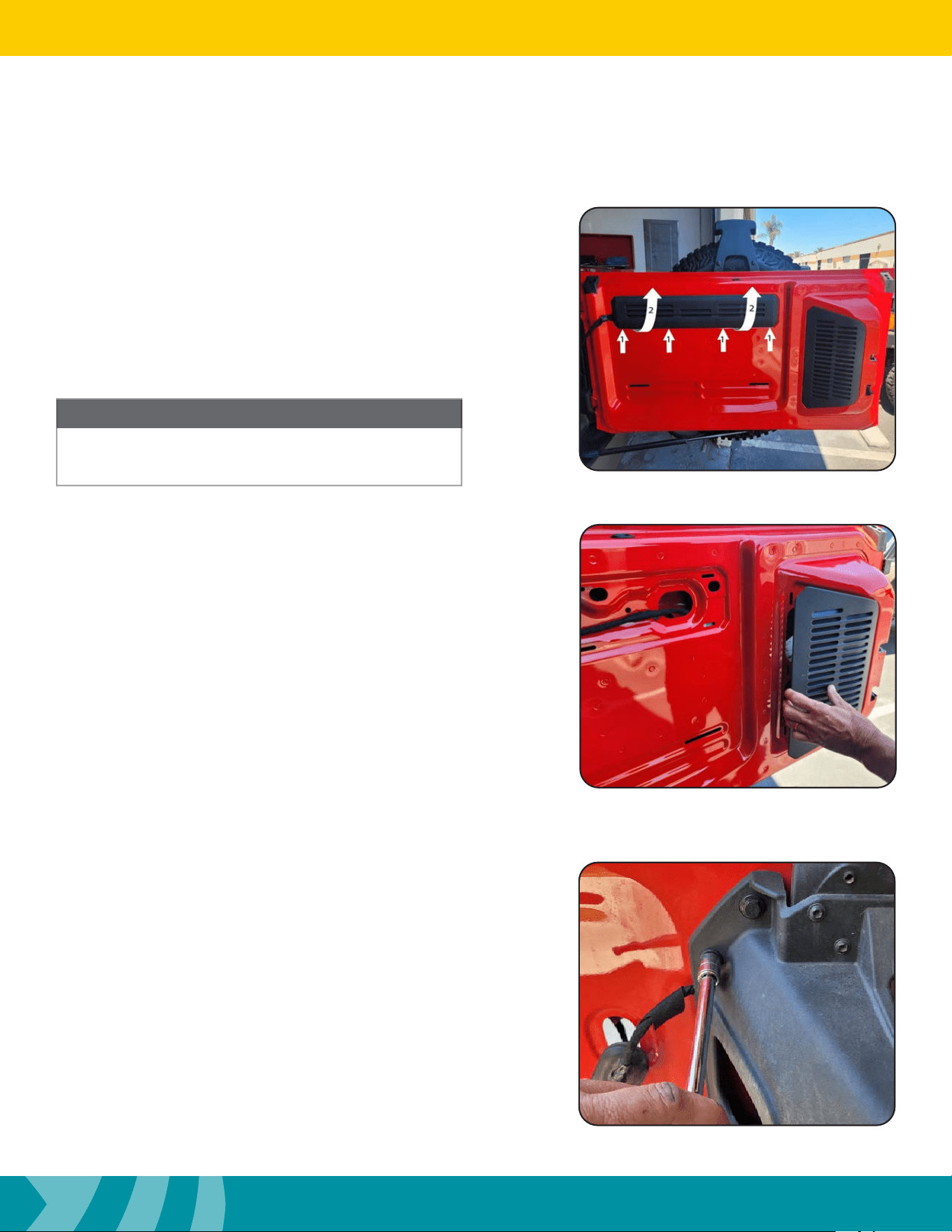
Step 1
Remove the trim panel on the inside of the tailgate by pulling it
away from the tailgate along the bottom of the panel from one side
to the other (1). en swing the panel upward to disengage the
upper tabs and pull down (2).
Step 2
Remove the vent panel on the inside of the tailgate by pulling
it away from the tailgate along the le side of the panel and
releasing the tabs on the right side.
Routing the Camera Cable
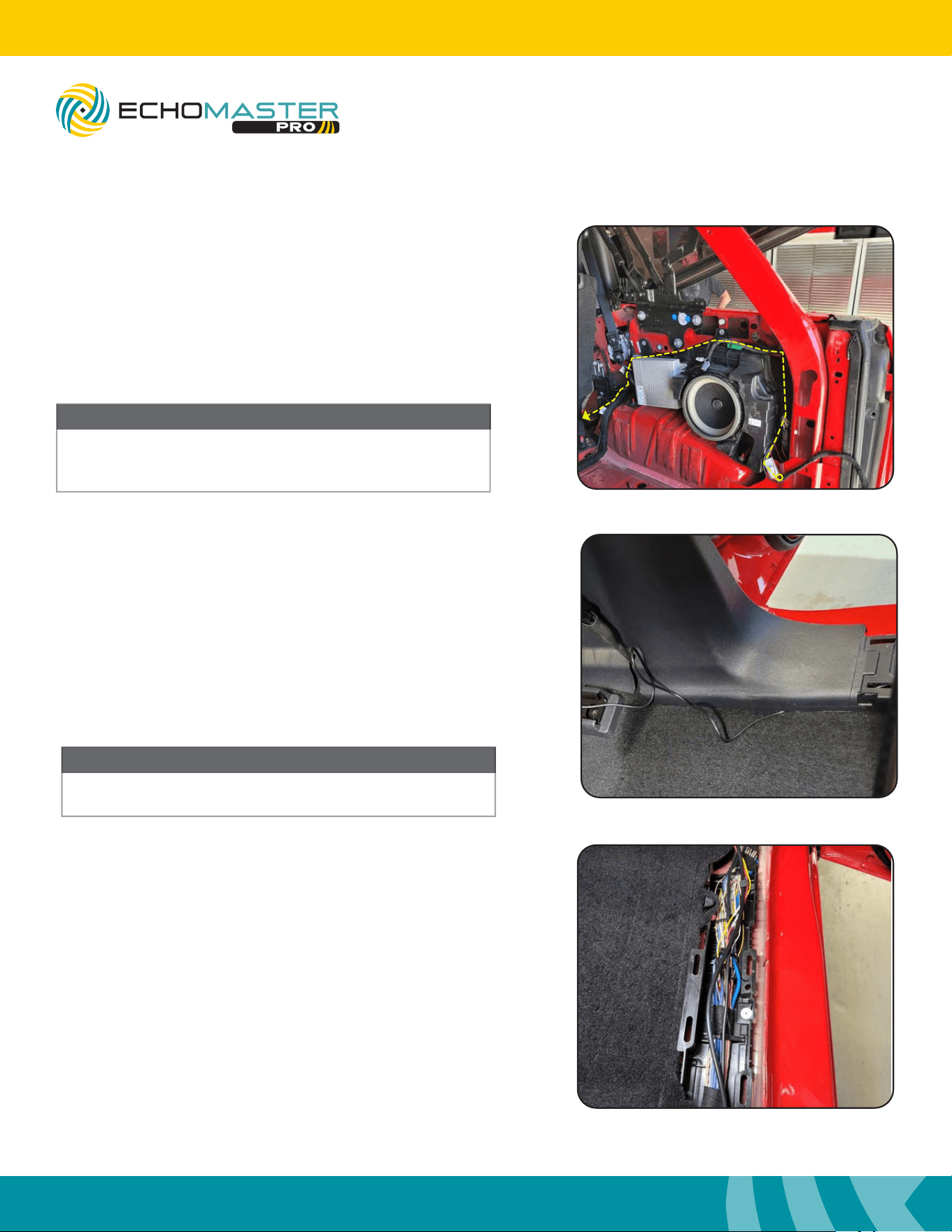
Step 3
Loosen the 14mm bolts holding the spare tire carrier bracket. Route
the camera cable through the opening in the top of carrier and
through the opening on the le side. Once the wire has been pulled
through you can re-tighten the 14mm bolts holding the spare tire
carrier bracket.
A plastic trim tool may be needed for the following panel
removal steps.
NOTE
10
Installation Guide
10
tel - 1-800-477-2267
email - support@echomaster.com
Illustrations are typical and may not match exact vehicle detail
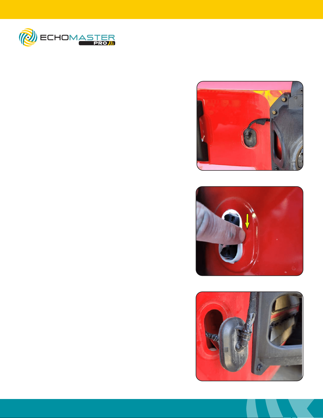
Routing the Camera Cable (cont)
Step 4
Remove the rubber grommet on the outside of the swing gate.
Step 5
Push the 4 plastic tabs holding the grommet in place from the inside
of the vent.
NOTE
Step 6
Cut the zip tie o the front of the grommet.
Remove the felt tape from the front and back of the grommet.
11
Installation Guide
11
tel - 1-800-477-2267
email - support@echomaster.com
Illustrations are typical and may not match exact vehicle detail
MRCHDDVRBR
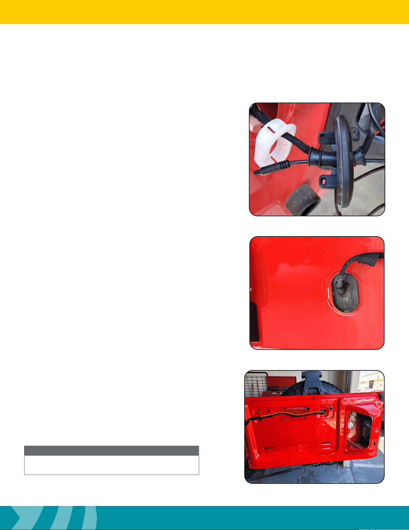
Routing the Camera Cable (cont)
Step 8
Push the grommet back into the swing gate and make sure it is
seated properly.
Step 7
Once the grommet has been untaped slide the camera wire into the
front of the grommet, coming out the back side.
Pull all the leover slack and retape front and back of the grommet.
Zip tie the harness back to the grommet.
Step 9
Using the vent opening to access the inside of the tailgate, feed
the camera cable out the access hole along with the factory wiring
harness. Zip tie camera harness to factory wire harness.
NOTE
e Yellow line indicates camera wire path.
NOTE
12
Installation Guide
12
tel - 1-800-477-2267
email - support@echomaster.com
Illustrations are typical and may not match exact vehicle detail
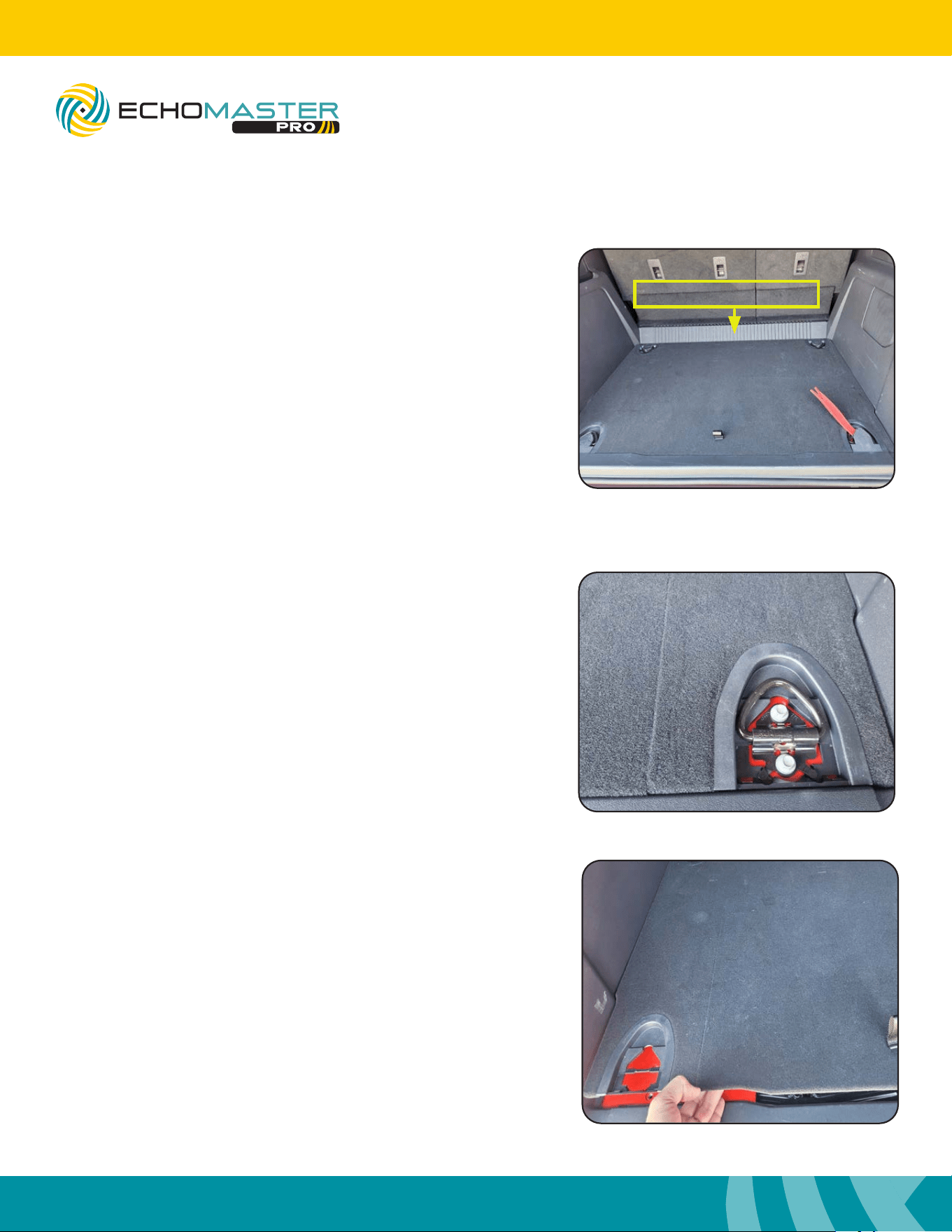
Routing the Camera Cable (cont)
Step 10
Pull straight up on the plastic panel against the back seat and
remove panel. Remove the 4 plastic covers hiding the oor bolts.
Step 11
Use a 10mm socket and remove the 8 bolts holding the tie downs in
place. Remove the tie downs and plastic cover and set aside.
NOTE
Step 12
Aer the 8 bolts are removed, pull up on the plastic oor and
remove the ooring.
Plastic Floor Trim-panel
13
Installation Guide
13
tel - 1-800-477-2267
email - support@echomaster.com
Illustrations are typical and may not match exact vehicle detail
MRCHDDVRBR
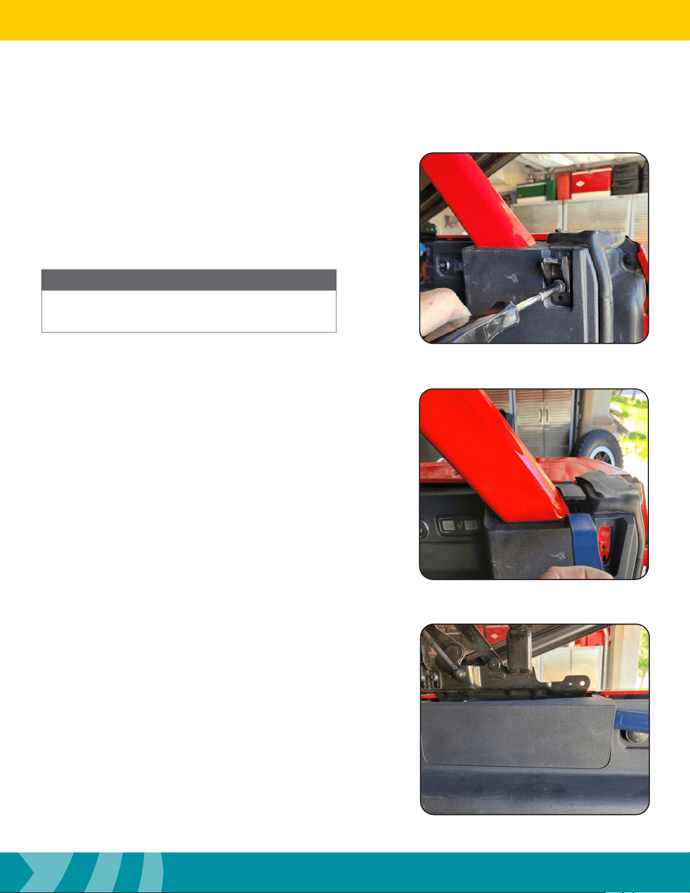
Routing the Camera Cable (cont)
Step 14
On the right side of the back of the Bronco, pop up the plastic trim
panel around the steel roll cage. Remove the trim panel and set
aside.
Step 13
With a 8mm socket, remove the 8mm bolt holding the steel bracket
and set aside.
Step 15
Remove the small plastic cover attached to the large plastic panel.
NOTE
Bracket will not be present for vehicles equipped with a hard
top.
NOTE
14
Installation Guide
14
tel - 1-800-477-2267
email - support@echomaster.com
Illustrations are typical and may not match exact vehicle detail
Step 16
From the back of the Bronco remove the plastic oor trim covering.
Step 17
Release the passenger rear large plastic panel from the rear sill panel.
Step 18
Remove the large plastic trim panel on the right rear side of the
Bronco. Start with pulling forward where the small plastic cover was
removed in step 15.
Routing the Camera Cable (cont)
15
Installation Guide
15
tel - 1-800-477-2267
email - support@echomaster.com
Illustrations are typical and may not match exact vehicle detail
MRCHDDVRBR
Unplug the interior light and/or power port on
the backside of the panel.
NOTE
Step 19
Release all the plastic snaps holding the panel on. With all the snaps
released, pull the trim panel towards the center of the vehicle to
remove it.
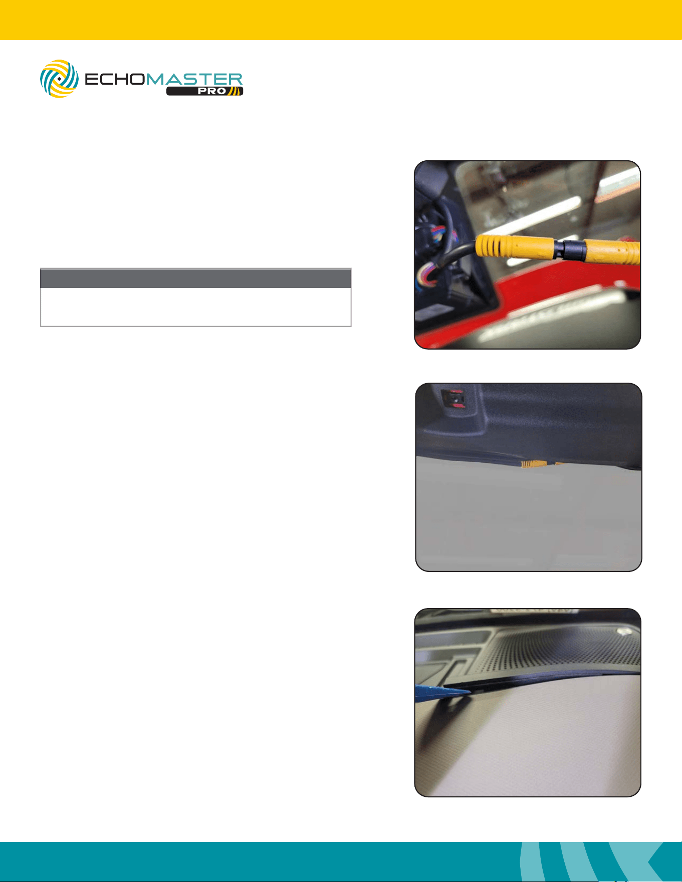
Step 20
Remove the felt tape on both ends of the factory fabric wire loom. Push
the black cable with the Red single wire through the wire loom. Place the
provided heat shrink onto the camera cable. Align the 2 Arrows of the
connectors. Once the connectors are aligned properly push them together.
Place the heat shrink over both connectors. Use a heat gun or lighter to
shrink the heat shrink around the two connectors.
Routing the Camera Cable (cont)
Not lining up the arrows of the connectors properly will
result in damage to the connectors.
NOTE
Step 21
With the camera cable connected and ran through the wire loom,
wrap both ends with fabric tape or similar type tape.
16
Installation Guide
16
tel - 1-800-477-2267
email - support@echomaster.com
Illustrations are typical and may not match exact vehicle detail
Step 23
Attach the Red reverse Trigger Wire on the camera’s extension cable
to the reverse wire of the vehicle.
Step 24
Remove the front passengers sill panel.
Routing the Camera Cable (cont)
Step 22
Locate the factory black 20 pin connector. Find the Green with Brown
Stripe wire (GRN/BRN) pin number 2 in the connector. Using a
multimeter, conrm the reverse wire shows 12V when in reverse. DO
NOT START THE VEHICLE. ENGAGE THE PARKING BRAKE. e
wire can be tested with just the ignition turned on.
17
Installation Guide
17
tel - 1-800-477-2267
email - support@echomaster.com
Illustrations are typical and may not match exact vehicle detail
MRCHDDVRBR
Step 25
Remove the passengers rear sill panel.
Routing the Camera Cable (cont)
Step 26
Remove the plastic trim panel located above the passenger kick
panel.
Step 27
Remove the passenger kick panel.
18
Installation Guide
18
tel - 1-800-477-2267
email - support@echomaster.com
Illustrations are typical and may not match exact vehicle detail
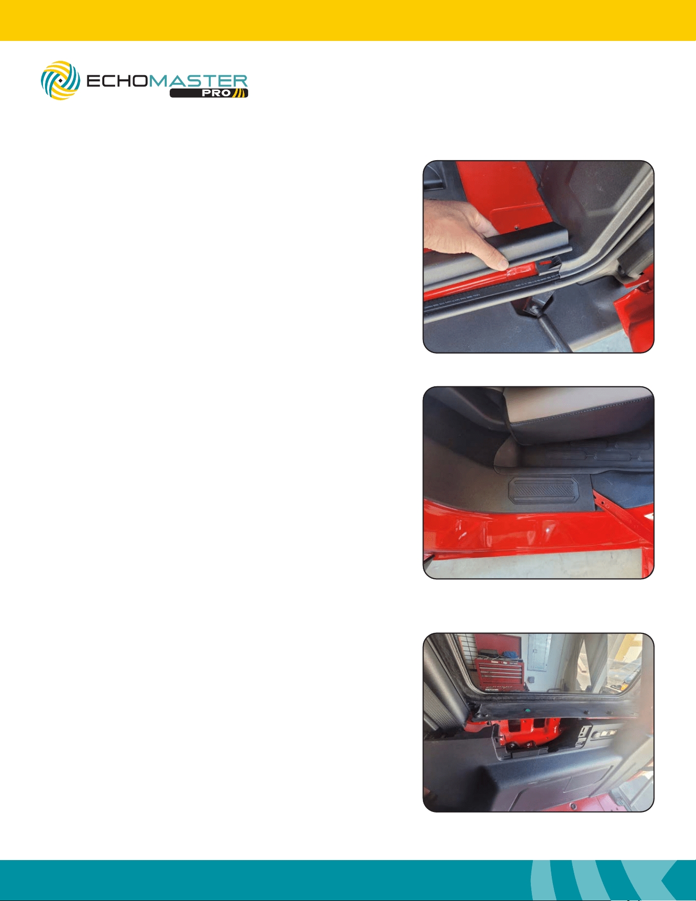
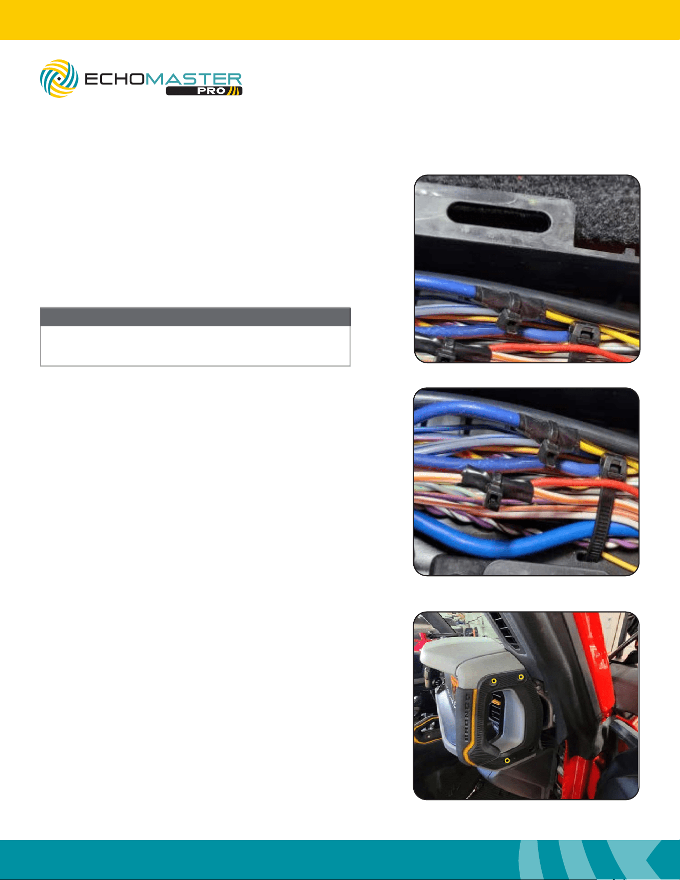
Step 29
Continue routing the camera wire down to the rear door seal panel
area. Push the wire under the moulding between the front and rear
door.
Step 30
Continue routing the camera wire following the factory wire
harness forward, across the door sill(s), up to the top of the kick
panel area. Secure with zip ties.
For 2 Door Broncos, skip to step 29
NOTE
Step 28
Route the camera cable from the bottom of the 20 pin connector
to the top of the factory harness and zip tie along the factory amp
harness.
NOTE
For vehicles without factory amp or subwoofer locate a route
that is similar for the camera wire harness.
Routing the Camera Cable (cont)
19
Installation Guide
19
tel - 1-800-477-2267
email - support@echomaster.com
Illustrations are typical and may not match exact vehicle detail
MRCHDDVRBR
Installing the Mirror & Harness
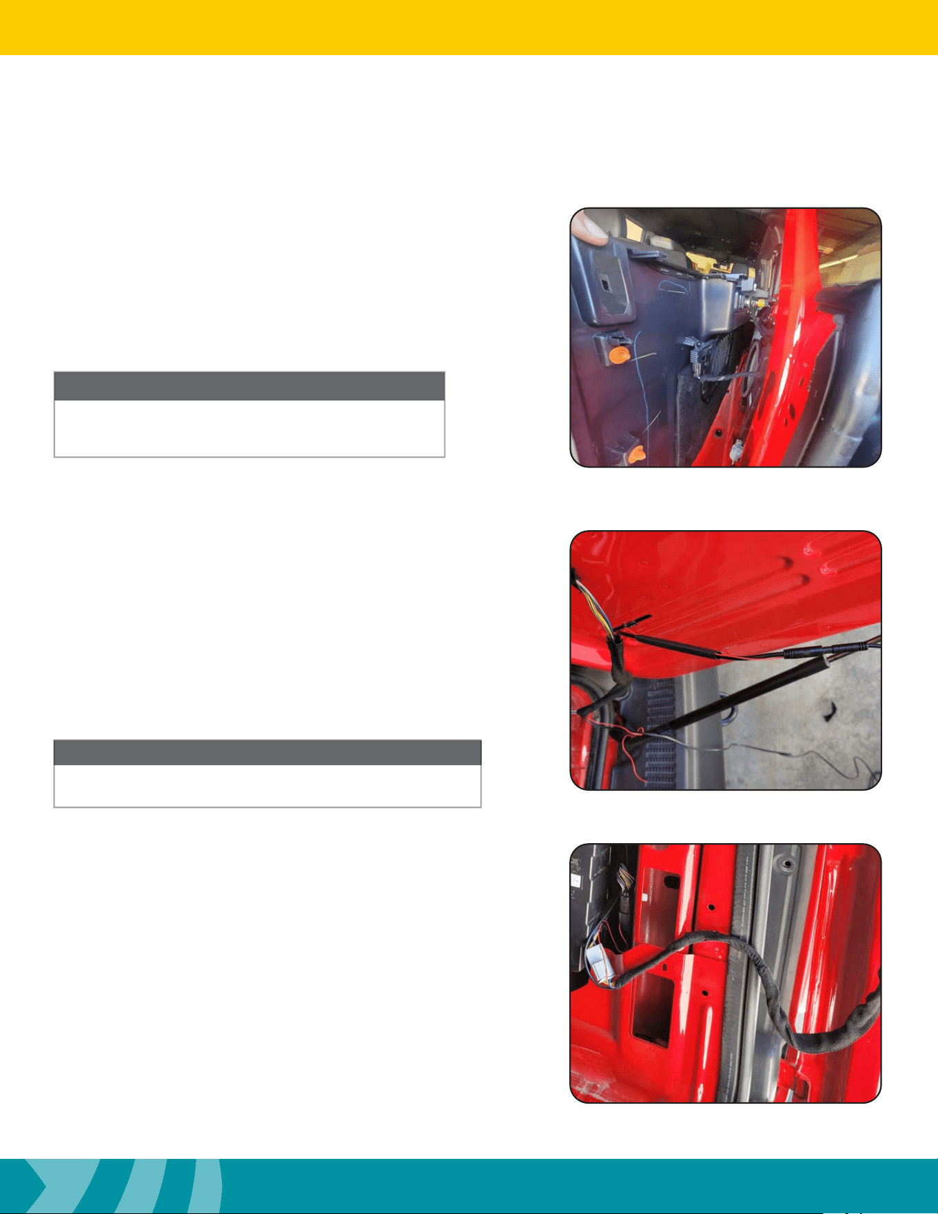
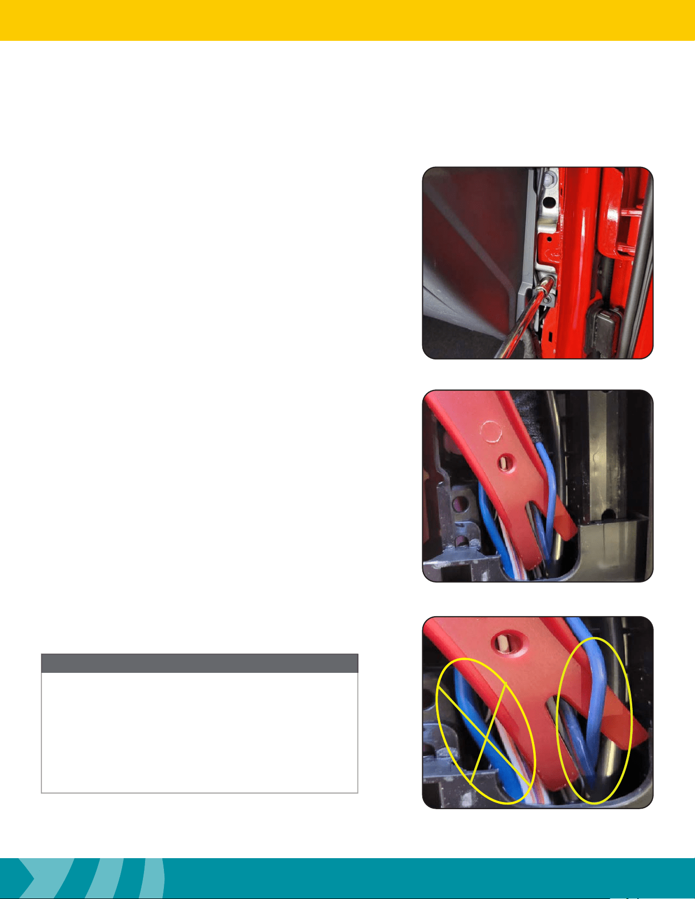
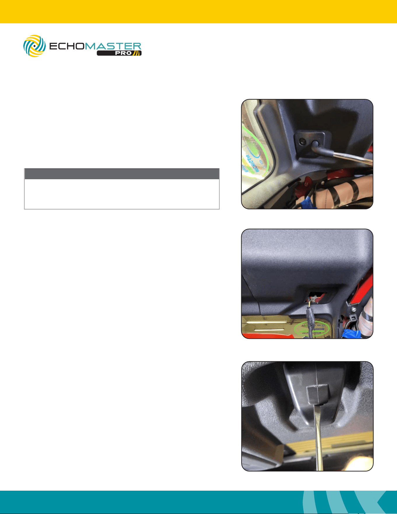
Step 2
Locate the Blue wire in the main factory wire harness located on
the front passenger oor where the door seal panel was located.
Step 1
Remove the 13mm bolt located above the kick panel. Place the
Black ground terminal located on the rear view mirror harness
behind the 13mm bolt. Tighten the 13mm bolt with the ground
wire.
For vehicles equipped with the Premium sound system
(B&O) ere are 2 large Blue wires. Do not probe or cut the
largest Blue wire. is wire is the Data for the factory amp.
e Blue wire your looking for should match the color of
the other Blue with Red stripe wire in the harness.
NOTE
Correct Wire
Wrong Wire
20
Installation Guide
20
tel - 1-800-477-2267
email - support@echomaster.com
Illustrations are typical and may not match exact vehicle detail
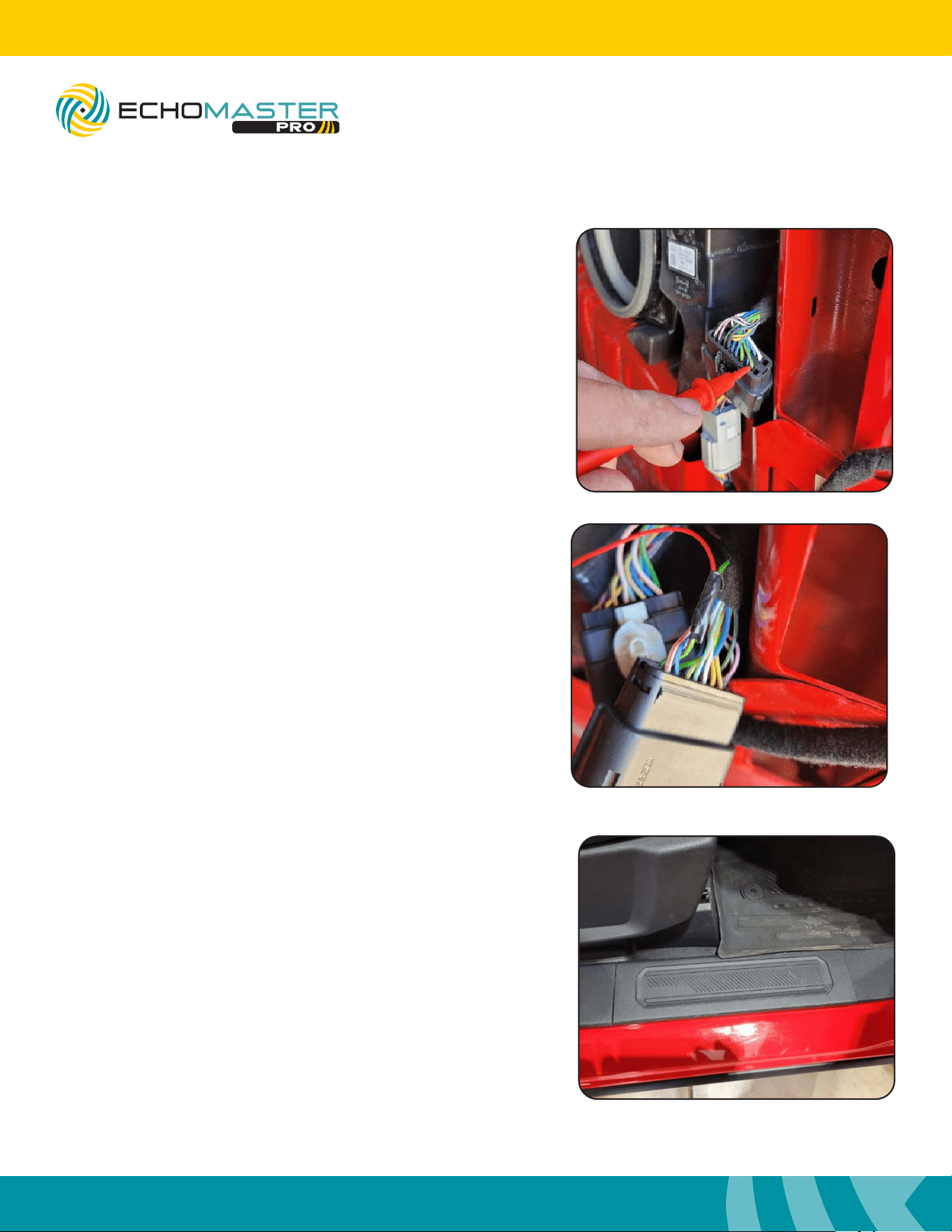
Step 3
Once you have located the correct Blue wire with a multi-meter
measure the voltage. You should have 12 volts or more. Connect the
Yellow Mirror wire to the vehicles Blue wire (12v wire).
Step 4
Locate the White with a Orange stripe (WHT/ORG) wire in the
factory wire harness. Turn the vehicle to Accessory or Run. With
a multi-meter measure the voltage. You should have 12 volts or
more. Connect the Mirror Red wire to this (WHT/ORG) wire.
Make sure to not touch the Blue wire to any grounded
surface.
NOTE
Installing the Mirror & Harness (cont.)
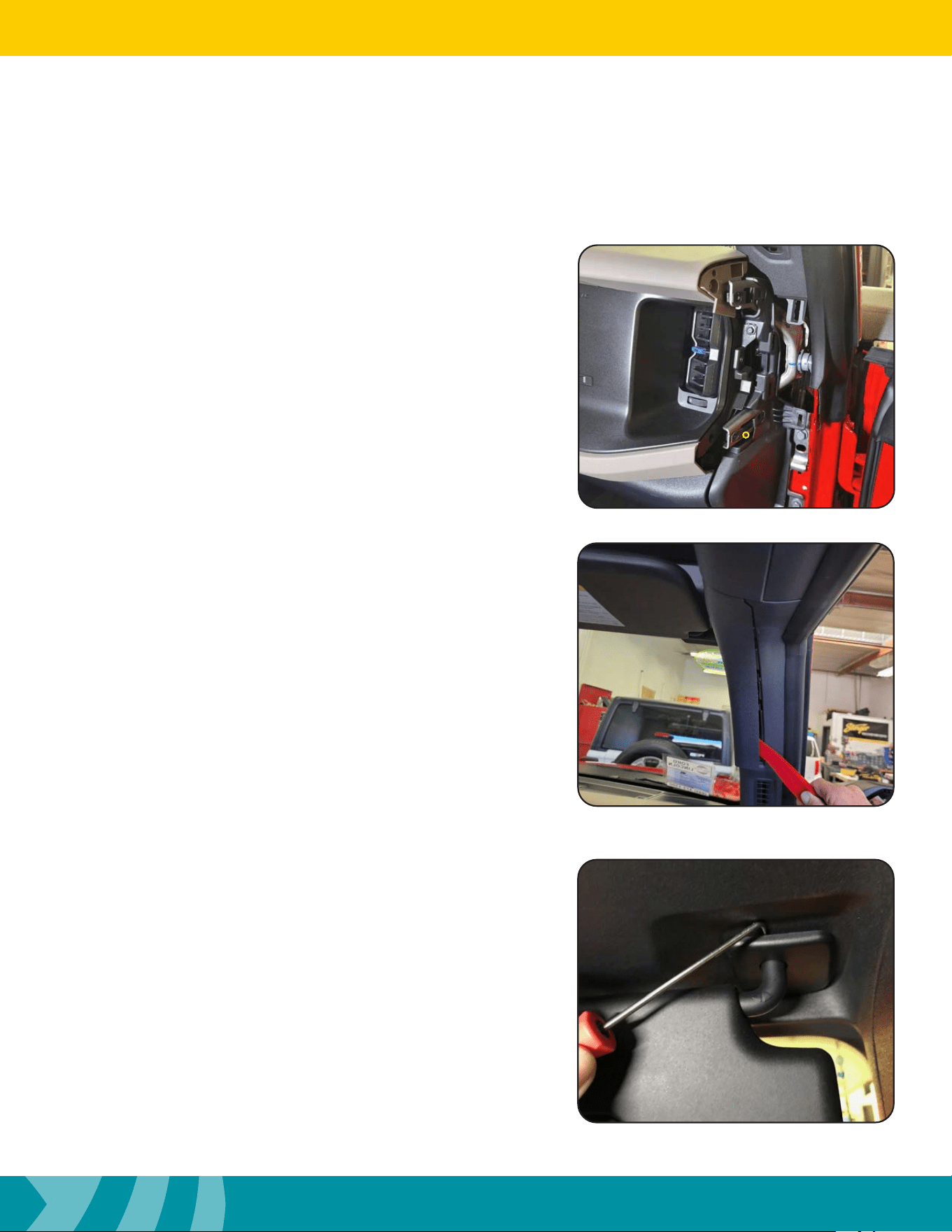
Step 5
Remove the 4 #30 Torx bolts holding the passenger side grab
handle.
21
Installation Guide
21
tel - 1-800-477-2267
email - support@echomaster.com
Illustrations are typical and may not match exact vehicle detail
MRCHDDVRBR
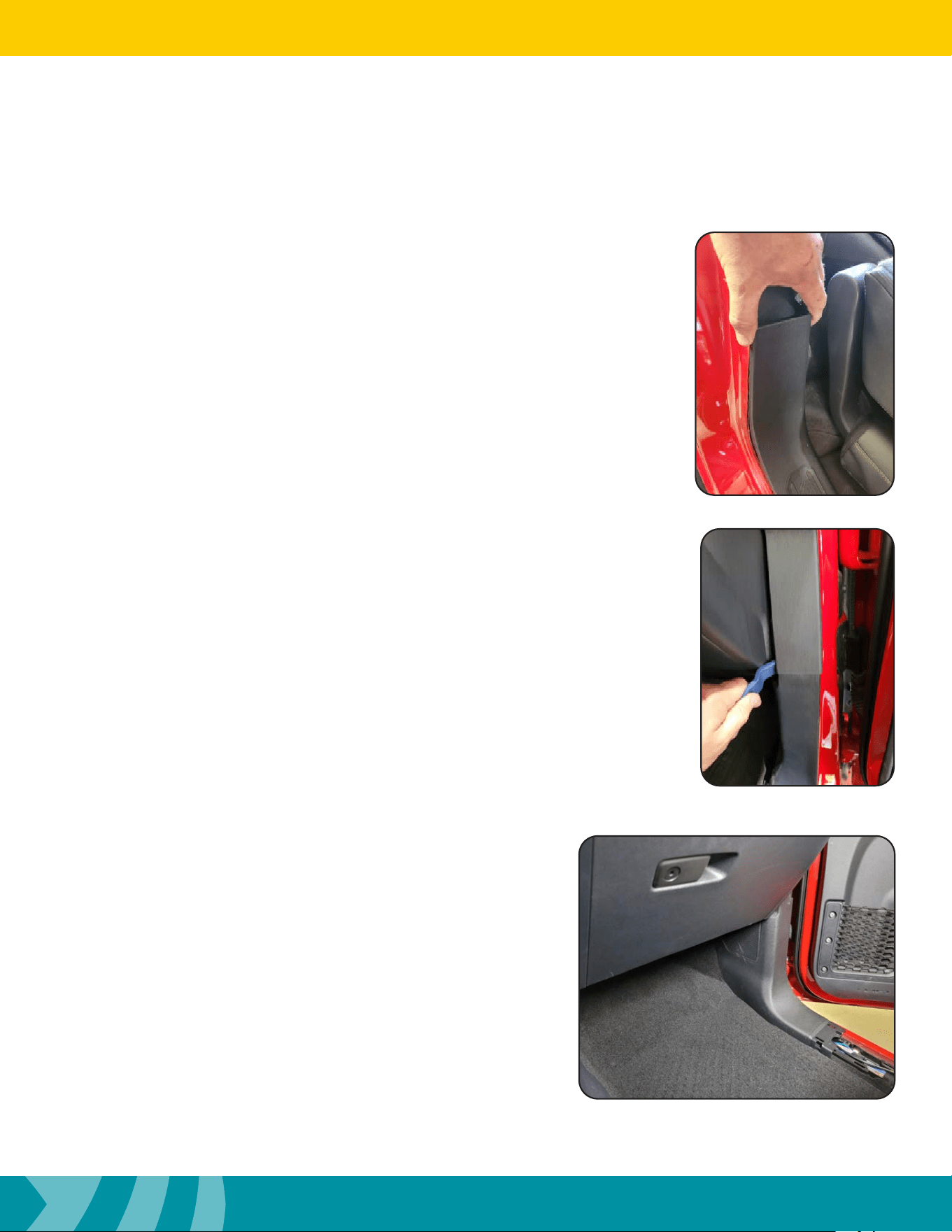
Step 6
Once all 4 bolts are removed pull the grab handle o and set aside.
Step 7
Release the plastic airbag trim cover on the passenger side A pillar.
Installing the Mirror & Harness (cont.)
Step 8
Open the passenger visor. With an angle pick tool remove the
plastic cover hiding the visor mount screw.
22
Installation Guide
22
tel - 1-800-477-2267
email - support@echomaster.com
Illustrations are typical and may not match exact vehicle detail
Installing the Mirror & Harness
Step 10
Disconnect the visor from the connector and set aside.
Step 9
Extend the visor until it is in the fully open position. Remove the
7mm screw holding the visor in place. Slide the visor out.
Once the visor has been unscrewed from the mount there will be a
wire from the vehicle connecting the visor.
NOTE
Step 11
With a small at head screw driver open the door hiding the screw
to remove the passenger visor retaining clip. With a #20 Torx
screw driver, remove the screw and pull the visor retaining clip o.
23
Installation Guide
23
tel - 1-800-477-2267
email - support@echomaster.com
Illustrations are typical and may not match exact vehicle detail
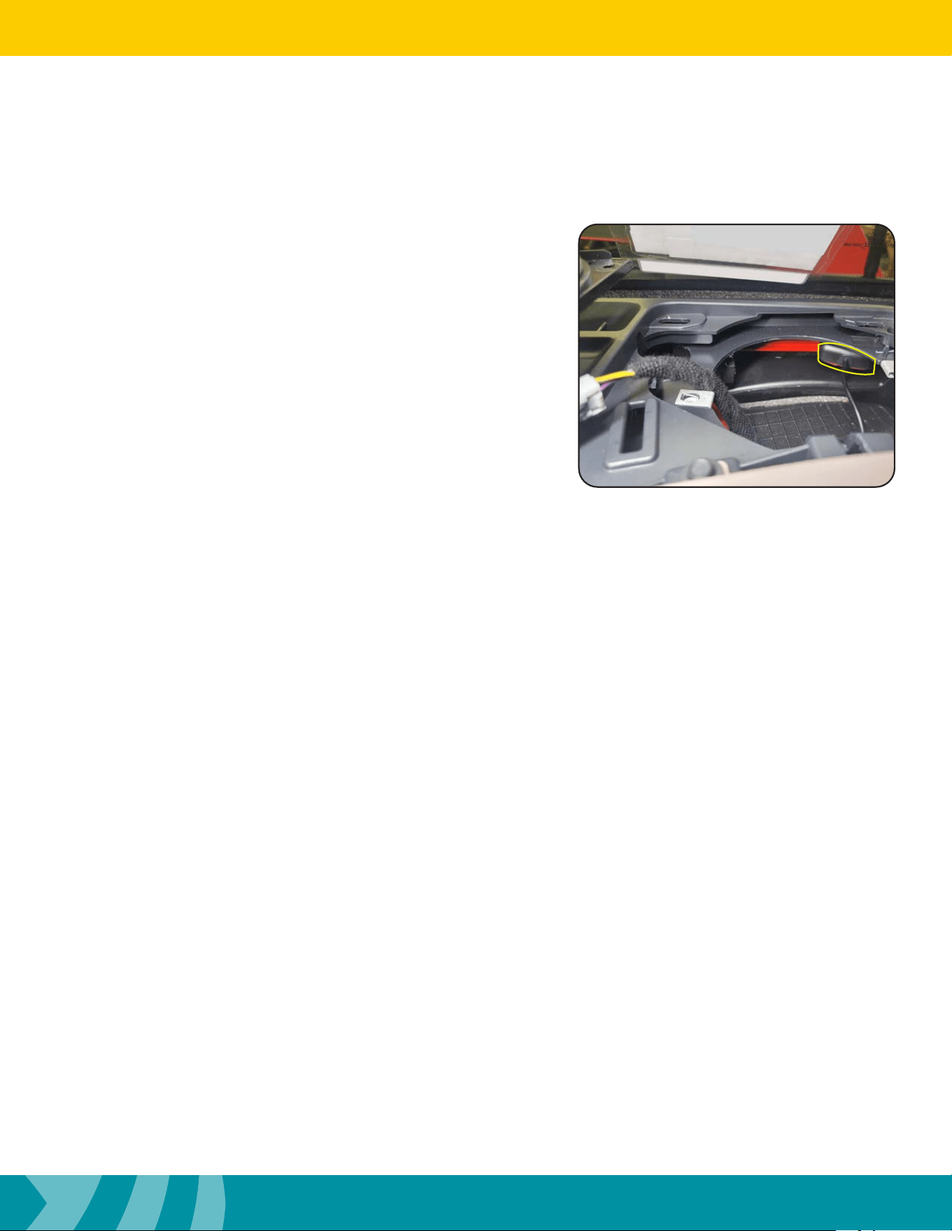
MRCHDDVRBR
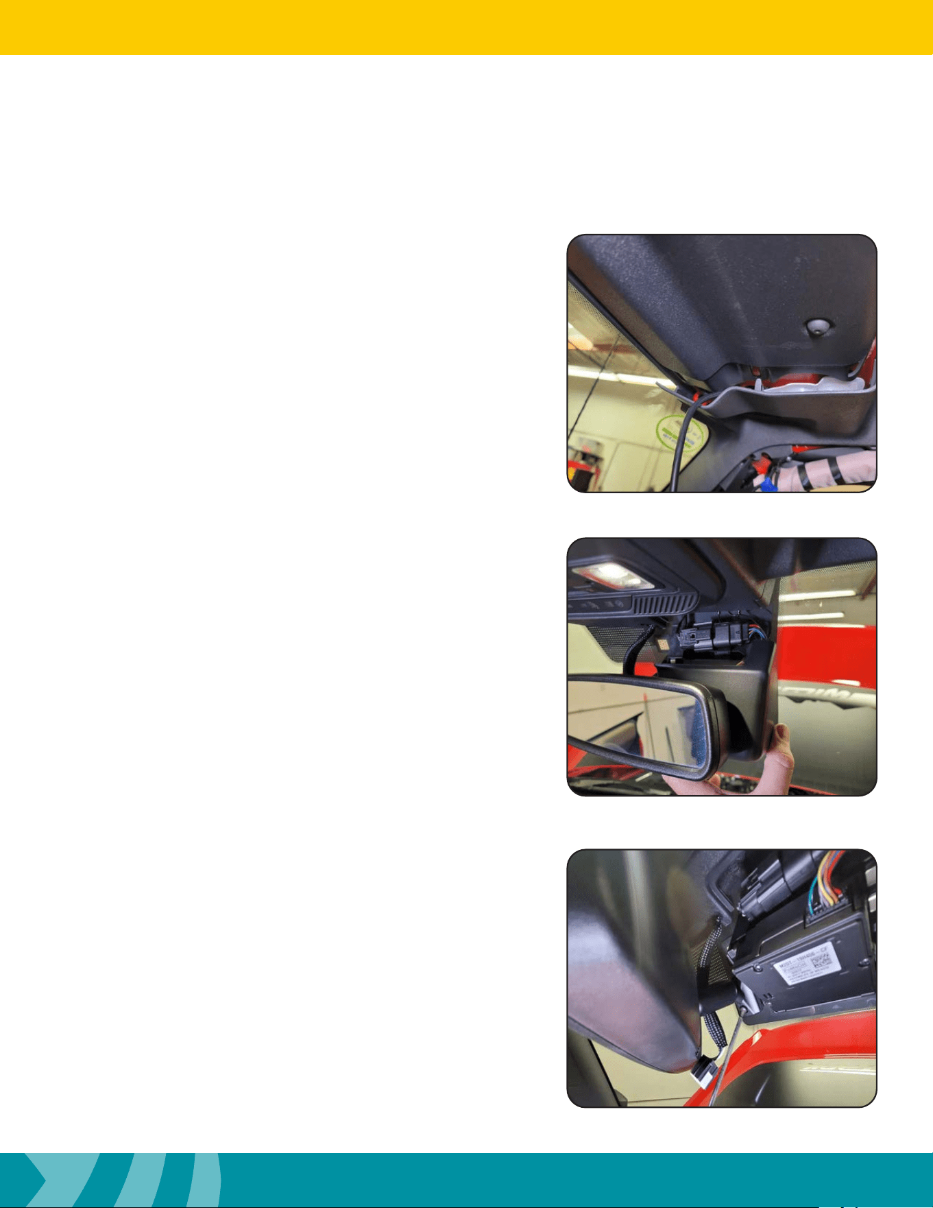
Step 12
Release the plastic panel behind the rear view mirror against the
windshield.
Step 14
Unscrew the #20 Torx bolt holding the rear view mirror. Li
mirror up and away from bracket holding the mirror in place.
Installing the Mirror & Harness (cont.)
Step 13
Remove the plastic cover behind the factory rear view mirror.
24
Installation Guide
24
tel - 1-800-477-2267
email - support@echomaster.com
Illustrations are typical and may not match exact vehicle detail
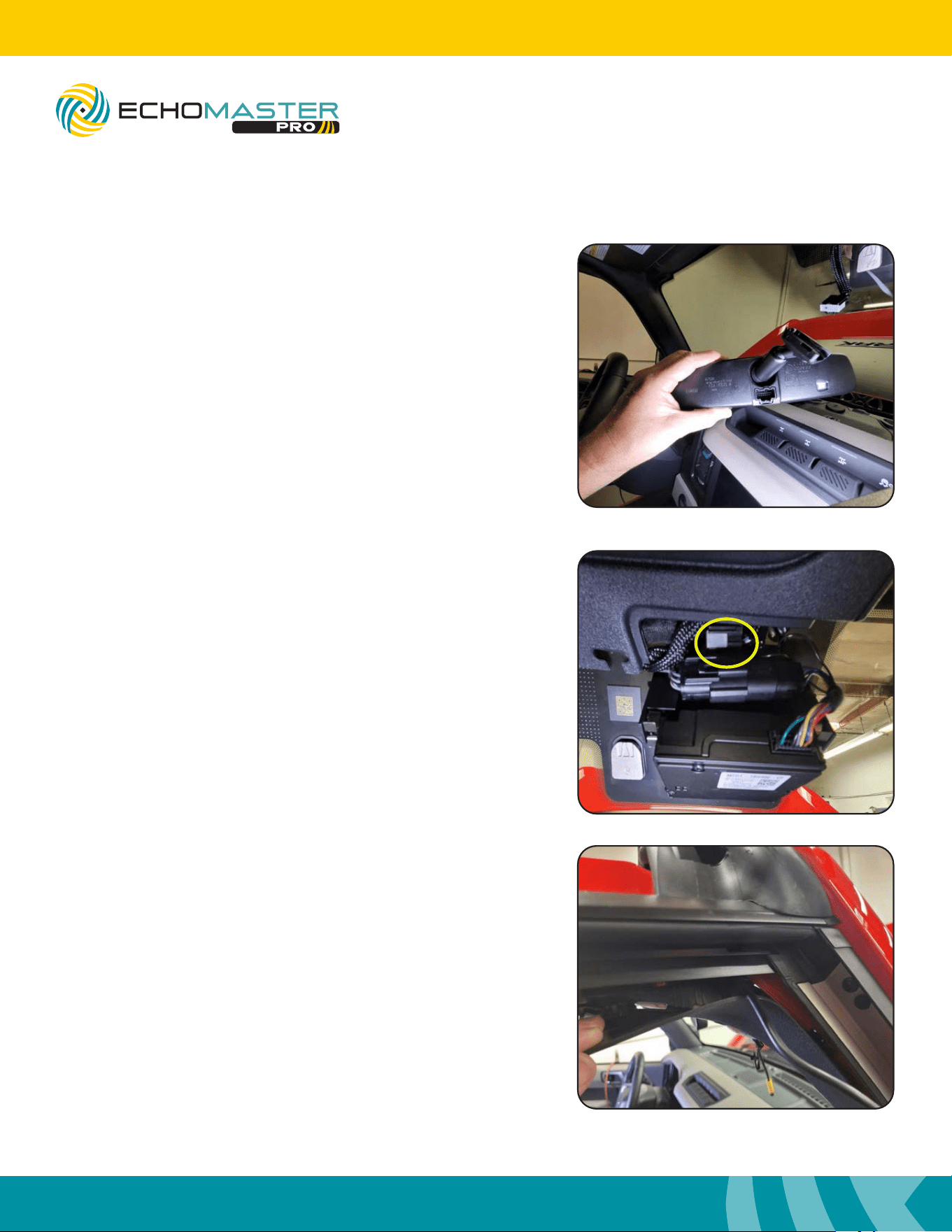
Step 17
Route the camera cable up the kick panel area and up to the top of
the plastic a-pillar. Open up the A-Pillar plastic panel enough to
push the cable through the opening.
Installing the Mirror & Harness (cont.)
Step 16
Route the factory rear view mirror harness to the center opening
where the mirror plastic cover was.
Step 15
Disconnect the connector located on the back-side of the rear view
mirror. Set rear view mirror aside.
25
Installation Guide
25
tel - 1-800-477-2267
email - support@echomaster.com
Illustrations are typical and may not match exact vehicle detail
MRCHDDVRBR
Step 19
Remove the (2) 8mm bolts holding the front passenger plastic roll
bar cover. Remove the roll bar cover and set. aside.
Installing the Mirror & Harness (cont.)
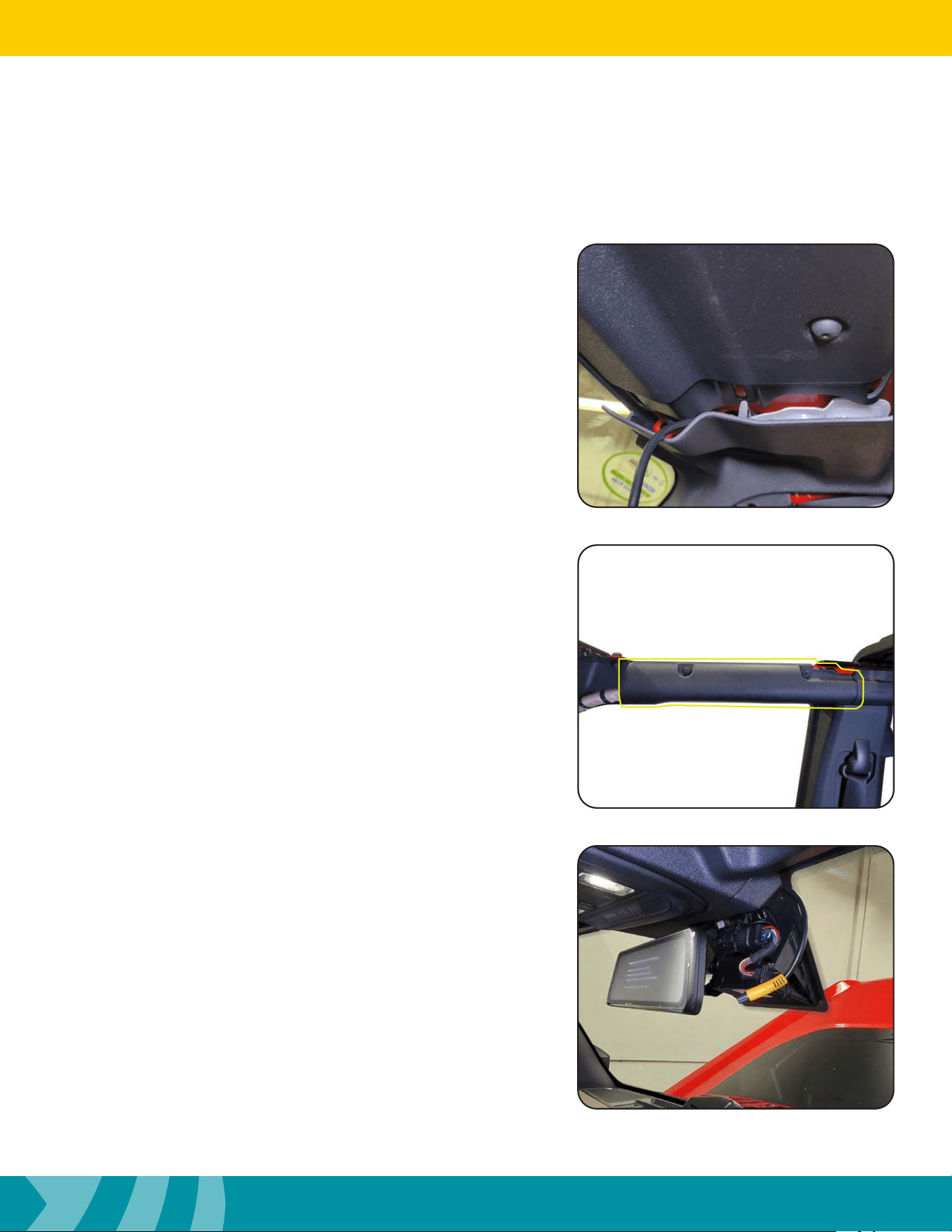
Step 18
Release the A-Pillar trim from the plastic roof panel.
Pull down on the panel and slide the cable from the outside of the
a-pillar to the inside.
Step 20
Attach the MRCHDDVR2 mirror to the factory mirror mount.
Tighten the Phillips screw using a #2 Phillips screw driver. Route
the mirror cable to where it comes out of the right side of the
plastic roof trim cover.
26
Installation Guide
26
tel - 1-800-477-2267
email - support@echomaster.com
Illustrations are typical and may not match exact vehicle detail
Step 22
Tuck the connector and the remaining mirror cable between the
glass and the plastic roof trim panel.
Step 23
Remove the passenger side front speaker grill. With a panel
remover tool start from the front of the grill against the dashboard
and release the snap clips. continue around the grill untill all snaps
are released. Remove the grill and set aside.
Installing the Mirror & Harness (cont.)
Step 21
Connect the 4 pin plug on the Camera Extension harness to the
matching plug on the mirror power/video harness.
Line up both arrows before seating connectors fully.
Not lining up the arrows properly will result in damaging
the connectors.
NOTE
27
Installation Guide
27
tel - 1-800-477-2267
email - support@echomaster.com
Illustrations are typical and may not match exact vehicle detail
MRCHDDVRBR
Step 24
Remove the factory speaker by unscrewing the (2) 7mm screws.
Set the speaker aside. Remove the tape on the bottom of the GPS
antenna. Place the GPS antenna on the metal ange under the
dash. Route the GPS wire under the dash and plug into the 3.5mm
jack on the Mirror.
Test and Enjoy
Aer the installation is complete, Operating Instructions start on
Page 11 of the User Manual included with the MRCHDDVR2
Questions?
Reach out to our Technical Support Team:
Phone: 727-592-5991
Email: support@aampglobal.com
Chat: EchoMaster.com

AGREEMENT: End user agrees to use this product in compliance with the instructions and terms of use above and with
all State and Federal laws. EchoMaster provides instructions and safety warnings with respect to this product and
disclaims all liability for any use not in conformity with those instructions or other misuse of its product. If you do not agree,
please discontinue use immediately and contact EchoMaster. This product is intended for off-road use and passenger
use only.
email - [email protected]
tel - 1-800-477-2267
15500 Lightwave Drive, Suite 202, Clearwater, Florida 33760
EchoMaster is a Power Brand of AAMP Global.
EchoMaster.com
IG-MRCHDDVRBR
REV. 071522