Loading ...
Loading ...
Loading ...
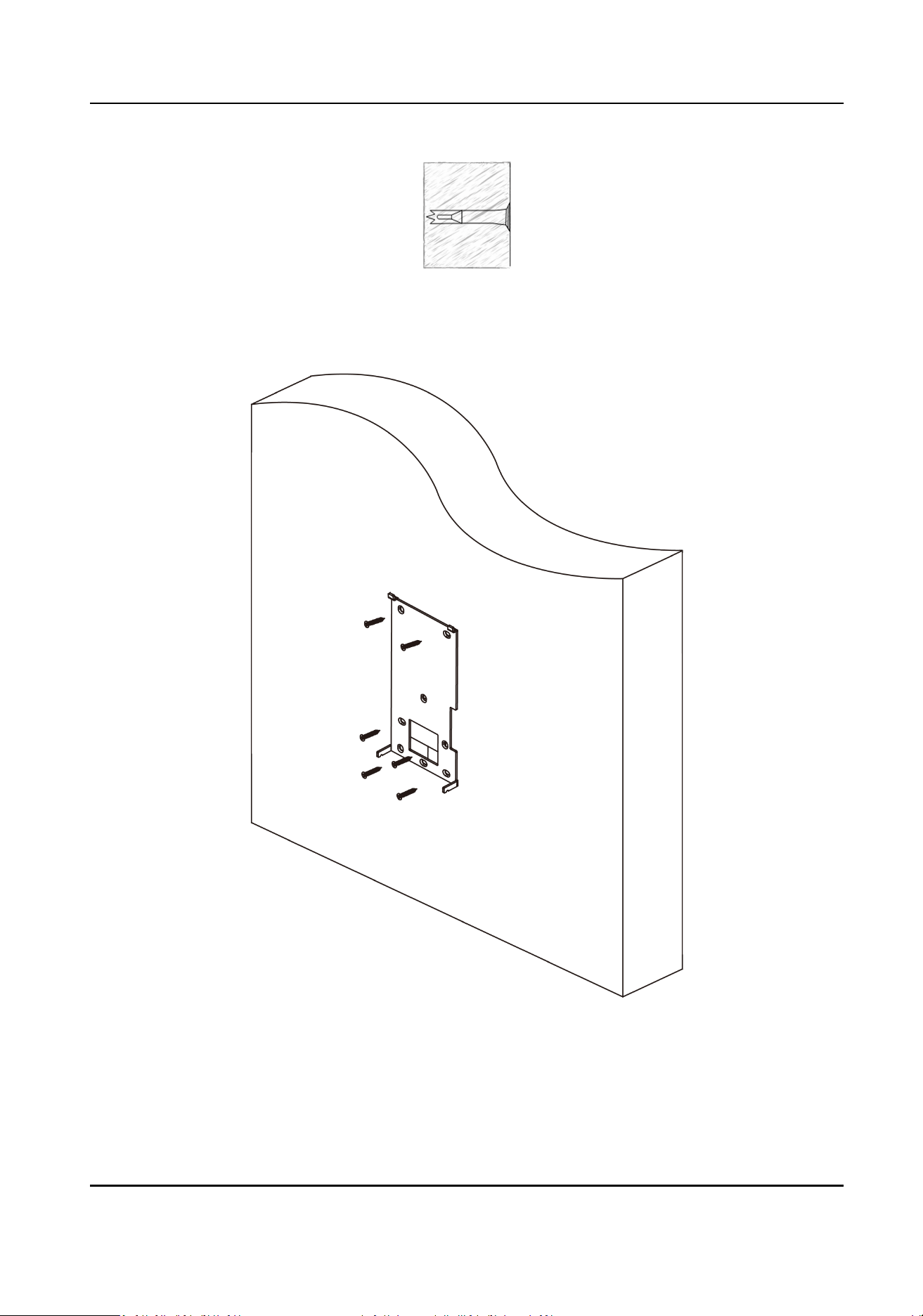
Figure 3-8 Insert Screw Socket
4.
Align the 6 holes to the mounng plate with the drilled holes.
Figure 3-9 Install Mounng Plate
5.
Remove the two screws on the rear panel and remove the sheet to display the wiring terminals.
6.
Route the cable through the cable hole of the mounng plate, and connect to corresponding
external devices' cables.
DS-K1T671 Series Face Recognion Terminal User Manual
12
Loading ...
Loading ...
Loading ...