Loading ...
Loading ...
Loading ...
Your model may differ.
5
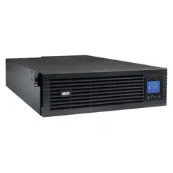
REMOTE ON CONFIGURATION:
USER SUPPLIED NORMALLY OPEN SWITCH
REMOTE OFF CONFIGURATION:
USER SUPPLIED NORMALLY OPEN SWITCH
GND
OFF
ON
VCC
GND
OFF
ON
VCC
27
Optional Connections
4
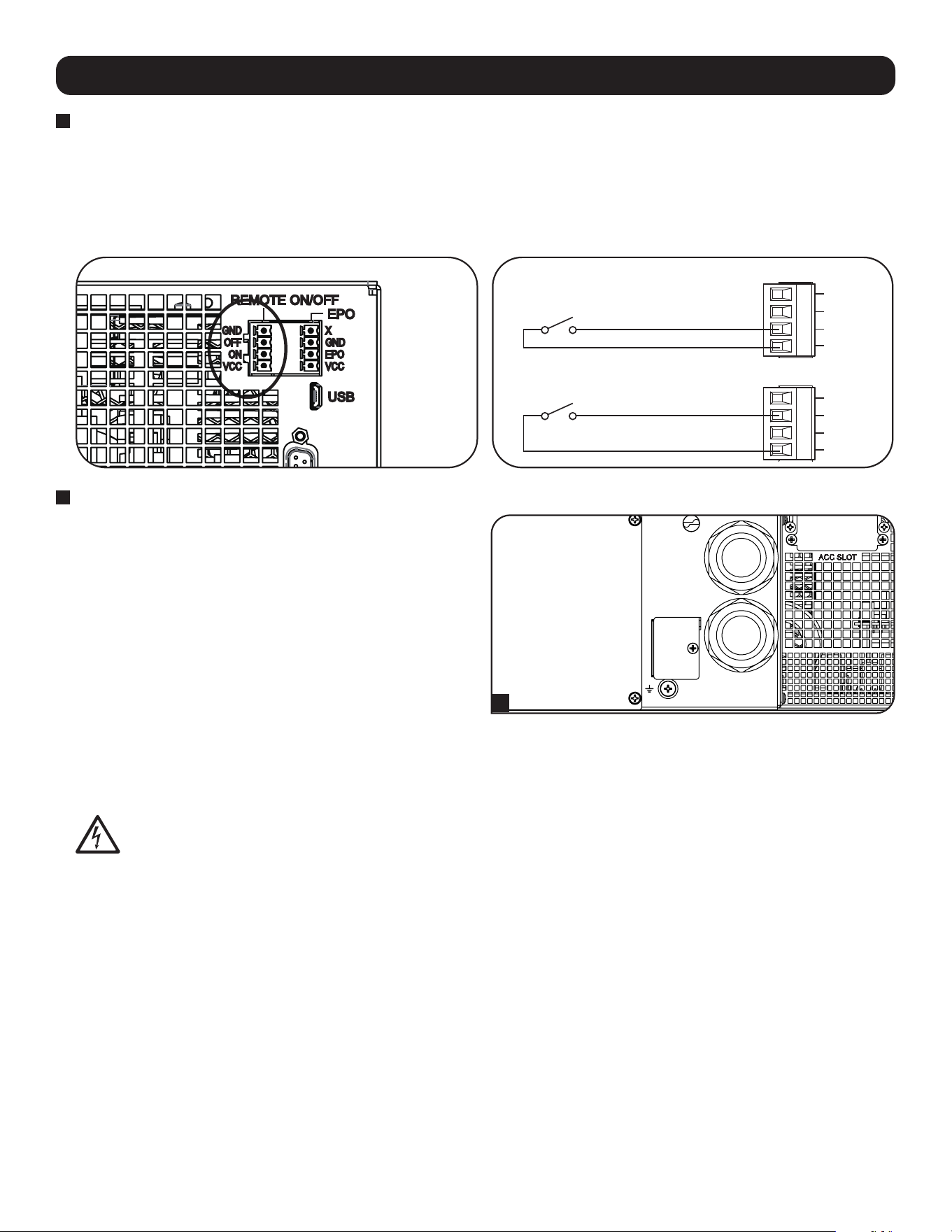
External Battery Connection
Check the Model Specific Accessories section under
Overview for compatible battery packs and maximum quantities
for your UPS system. Ensure that your battery pack matches the
voltage listed next to your UPS battery connector. Adding
external batteries will increase runtime as well as recharge time.
See the battery pack owner’s manual for complete installation
and setup instructions. Make sure to attach the ground wire of
the battery cable to the ground screw located near the DC
connector first. Connect the DC connector and make sure it is
fully inserted into its connectors prior to securing it with the
thumbscrew. Small sparks may result during battery connection;
this is normal. Do not connect or disconnect battery packs when
the UPS is running on battery power.
IMPORTANT! In order for the runtime-remaining LCD and the software information screens to accurately predict runtime with
external battery packs connected, you must configure via the Smart battery communication method (limit 4 Smart battery
packs), via the front panel LCD or Tripp Lite’s External Battery Configuration software. See Configuring External Battery
Packs section under Operations.
When installing an external battery pack, observe all external battery warnings in the Important Safety
Instructions section of this manual and follow the external battery pack installation instructions.
3
Remote ON/OFF Configuration
This feature is intended for switching the UPS to Bypass Mode for the Remote OFF configuration, or to Line Mode for the Remote ON
configuration.
Note: The 4-pin terminal block supports wire gauges from 14-30 AWG with a strip length of 7 mm. The M2 terminal screws should be tightened
between 0.22~0.25 Nm. Note: Before activating the Remote ON function, verify the AC input is present and valid.
Note: Before activating the Remote ON function, verify the AC input is present and valid. The 4-pin terminal block supports wire gauges from
14-30 AWG with a strip length of 7 mm. The M2 terminal screws should be tightened between 0.22~0.25 Nm.
Loading ...
Loading ...
Loading ...