C
US
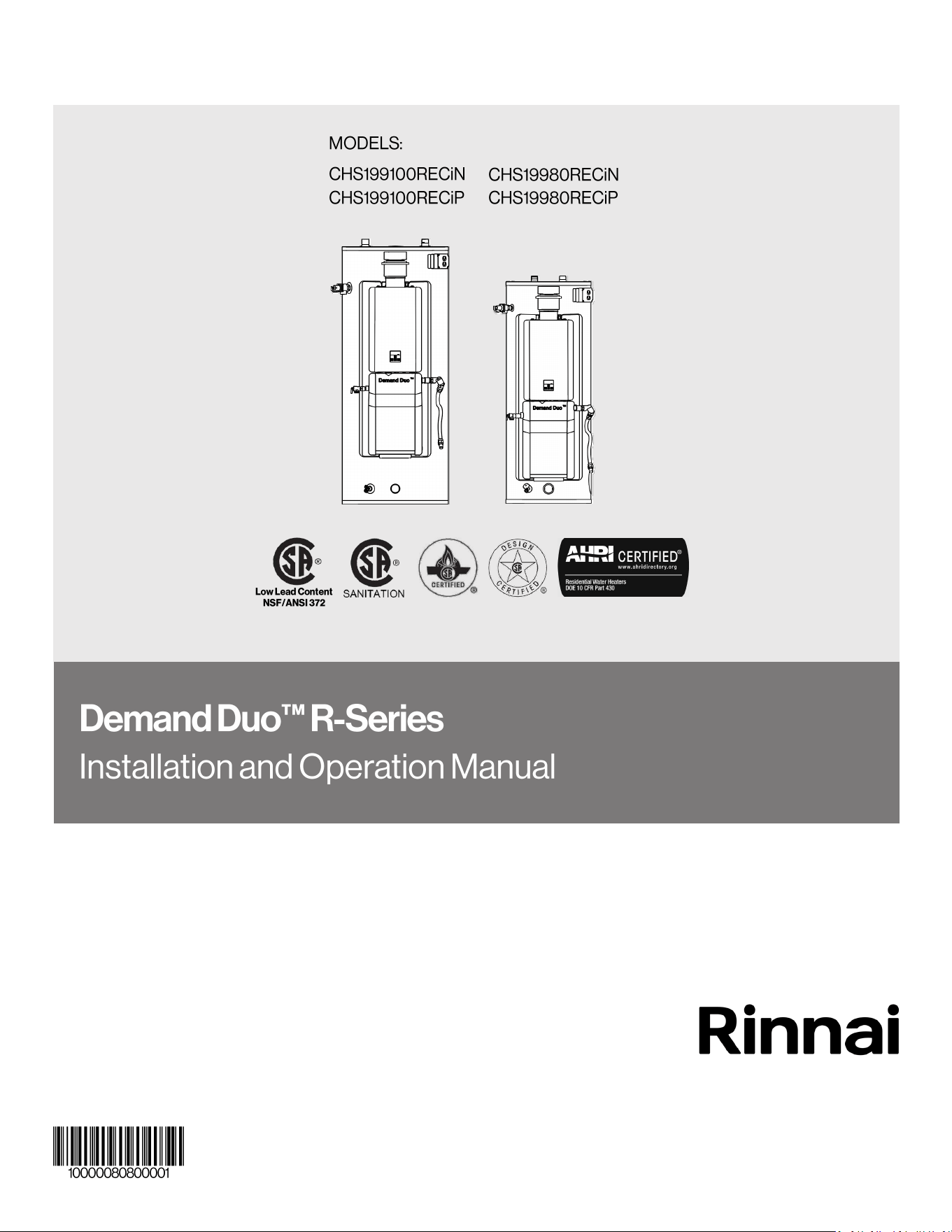
2 Demand Duo™ R-Series (REC) Installation and Operation Manual
— Do not store or use gasoline or other flammable vapors and liquids in the
vicinity of this or any other appliance.
— WHAT TO DO IF YOU SMELL GAS
• Do not try to light any appliance.
• Do not touch any electrical switch; do not use any phone in your building.
• Immediately call your gas supplier from a neighbor’s phone. Follow the
gas supplier’s instructions.
• If you cannot reach your gas supplier, call the fire department.
— Installation and service must be performed by a qualified installer, service
agency or the gas supplier.
IF THE INFORMATION IN THESE INSTRUCTIONS IS NOT FOLLOWED EXACTLY,
A FIRE OR EXPLOSION MAY RESULT CAUSING PROPERTY DAMAGE,
PERSONAL INJURY OR DEATH.
READ ALL OF THE INSTRUCTIONS THOROUGHLY BEFORE INSTALLING OR
OPERATING THIS WATER HEATER.
This manual provides information on the installation, operation, and maintenance of the water
heater. For proper operation and safety, it is important to follow the instructions and adhere to
the safety precautions.
A licensed professional must install the water heater according to the exact instructions in this
document.
The owner must read the entire manual to properly operate the water heater and understand
maintenance requirements.
This product is for indoor commercial applications only.
This product is NOT intended for residential applications.
WARNING
WARNING

Demand Duo™ R-Series (REC) Installation and Operation Manual 3
1. Welcome ...................................................................................................................................... 4
1.1 To the Installer ....................................................................................................................... 4
1.2 To the Owner ......................................................................................................................... 4
2. Safety ........................................................................................................................................... 5
2.1 Safety Symbols ...................................................................................................................... 5
2.2 Safety Precautions ................................................................................................................. 5
3. About the Water Heater ............................................................................................................... 7
3.1 Components ........................................................................................................................... 7
3.2 Specifications ......................................................................................................................... 8
3.3 Dimensions ............................................................................................................................ 10
4. Installation .................................................................................................................................... 12
4.1 Installation Guidelines ............................................................................................................ 12
4.2 What You Will Need ............................................................................................................... 13
4.3 Choose an Installation Location ............................................................................................. 13
5. Venting ......................................................................................................................................... 16
5.1 Venting Requirements............................................................................................................ 16
5.2 Combustion Air Requirements ............................................................................................... 21
5.3 Venting Installation Checklist ................................................................................................. 24
6. Gas and Power Supply ................................................................................................................. 25
6.1 Connect the Gas Supply ........................................................................................................ 25
6.2 Gas Operating Instructions .................................................................................................... 27
6.3 Gas Pipe Sizing Reference Tables ........................................................................................ 28
6.4 Connect Electricity ................................................................................................................. 29
6.5 Checklist for Gas and Electricity ............................................................................................ 30
7. Configure Parameter Settings....................................................................................................... 31
7.1 Instructions ............................................................................................................................. 31
7.2 Service Indicator (Service Soon, SS) ...................................................................................... 32
8. System Plumbing .......................................................................................................................... 33
8.1 PRV Requirements ................................................................................................................ 33
8.2 T&P Relief Requirements....................................................................................................... 33
8.3 Typical Installations ................................................................................................................ 34
8.4 Piping Diagram for Basic Installations .................................................................................... 35
8.5 Piping Diagram for Multiple Unit Installations ......................................................................... 36
8.6 Connect the Water Heater to the Water Supply ..................................................................... 37
8.7 Plumbing Checklist ................................................................................................................ 37
9. Post-Installation Checklist ............................................................................................................. 38
10. Operation .................................................................................................................................... 39
10.1 Safety Precautions ............................................................................................................... 39
10.2 Control Panel ....................................................................................................................... 40
10.3 Basic Operation Settings ...................................................................................................... 41
11. Maintenance ............................................................................................................................... 43
11.1 Performance Data ................................................................................................................ 46
11.2 Diagnostic Codes ................................................................................................................. 47
12. Warranty ..................................................................................................................................... 50
4 Demand Duo™ R-Series (REC) Installation and Operation Manual
• A trained and qualified professional must
install the system, inspect it, and leak test it
before use. The warranty may be voided due
to any improper installation.
• The trained and qualified professional should
have skills such as:
− Gas line sizing
− Connecting gas lines, water lines, valves,
and electricity
− Knowledge of applicable national, state,
and local codes
− Installing and routing B-Vent through a
roof
− Training in installation of water heaters.
Training on Rinnai Water Heaters is
accessible at
www.rinnaipro.myabsorb.com.
• Read all instructions in this manual before
installing the system. The system must be
installed according to the exact instructions in
this manual.
• Proper installation is the responsibility of the
installer.
• When installation is complete, leave this
manual with the system or give the manual
directly to the owner.
• You must read the entire manual to properly
operate the water heater and understand
maintenance requirements.
• Keep this manual for future reference.
• When using any appliance generating heat,
there are certain safety precautions you
should follow. See section “2.2 Safety
Precautions” for detailed safety precautions.
• Be sure your water heater is installed by a
trained and qualified professional.
For Your Records
Dealer Name:
Dealer Phone #:
Purchase Date:
Tank Serial #:
System Serial #:
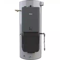
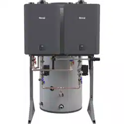
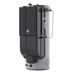
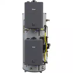
Thank you for purchasing Rinnai’s Demand
Duo™ R-Series Commercial Automatic
Circulating Tank Water Heater. This manual
provides information on the installation, operation,
and maintenance of Rinnai’s Demand Duo™
R-Series Commercial Automatic Circulating Tank
Water Heater. Read this manual completely
before installing or operating the system.
Demand Duo™ R-Series (REC) Installation and Operation Manual 5
This is the safety alert symbol. This
symbol alerts you to potential hazards
that can kill or hurt you and others.
Indicates an imminently
hazardous situation which,
if not avoided, will result in personal injury or
death.
Indicates a potentially
hazardous situation
which, if not avoided, could result in minor or
moderate injury. It may also be used to alert
against unsafe practices.
DANGER
CAUTION
Indicates a potentially
hazardous situation
which, if not avoided, could result in personal
injury or death.
WARNING
WARNING
− Turn off the gas at the gas valve, usually
located immediately before the water heater.
− Turn off the incoming water supply. This can
be done at the isolation valve
immediately before the water heater or by
turning off the water supply to the building.
• Use only your hand to push in or turn the gas
control knob. Never use tools. If the knob will not
push in or turn by hand, DO NOT try to
repair it; call a licensed professional. Force or
attempted repair may result in a fire or
explosion.
• DO NOT use this appliance if any part has been
under water. Immediately call a
licensed professional to inspect the
appliance and to replace any part of the
control system and any gas control which has
been under water.
• DO NOT use substitute materials. Use only parts
certified for the appliance.
• Should overheating occur or the gas supply fail
to shut off, turn off the manual gas control valve
to the appliance.
• DO NOT adjust the parameter settings unless
specifically instructed to do so. Only trained and
qualified professionals are permitted to adjust
parameter settings.
• DO NOT use an extension cord or an adapter
plug with this appliance.
• Any alteration to the appliance or its controls
may be dangerous and will void the warranty.
• Proper venting is required for the safe
operation of this appliance with 6 in. B-Vent or
greater. Refer to this manual or NFPA 54, and/or
CSA B149.1 for proper venting techniques for
fan-assisted Category 1 appliances.
• If a water heater is installed in a closed water
supply system, such as one having a
backflow preventer in the cold water supply line,
means shall be provided to control
thermal expansion. Contact the water
supplier or local plumbing inspector on how to
control thermal expansion.
• Keep the air intake location free of chemicals
such as chlorine or bleach that produce
fumes. These fumes can damage
components and reduce the life of your
appliance.
• Corrosive fumes, sometimes found in hair/ nail
salons, spas, or other industries exposed to toxic
fumes, may be released through these vents
when not in operation. Chemicals that are
corrosive in nature should not be stored or used
near the water heater or vent termination.
• You must follow the installation instructions and
those in section “11. Maintenance” for
adequate combustion air intake and exhaust.
• Make sure the water heater and its water lines
are protected from freezing. Damage due to
freezing is not covered by the warranty.
• Before operating, smell all around the
appliance area for gas. Be sure to smell next
to the floor because some gas is heavier than
air and will settle on the floor.
• Keep the area around the appliance clear and
free from combustible materials, gasoline, and
other flammable vapors and liquids.
• Combustible construction refers to adjacent
walls and ceiling and should not be confused
with combustible or flammable products and
materials. Combustible and/or flammable
products and materials should never be stored
in the vicinity of this or any gas appliance.
• Always check the water temperature before
entering a shower or bath.
• To protect yourself from harm, before
performing maintenance:
− Turn off the electrical power supply by
unplugging the power cord or by turning off
the electricity at the circuit breaker. (The
“On/Off” button on the temperature control-
ler does not control the electrical power.)
6 Demand Duo™ R-Series (REC) Installation and Operation Manual
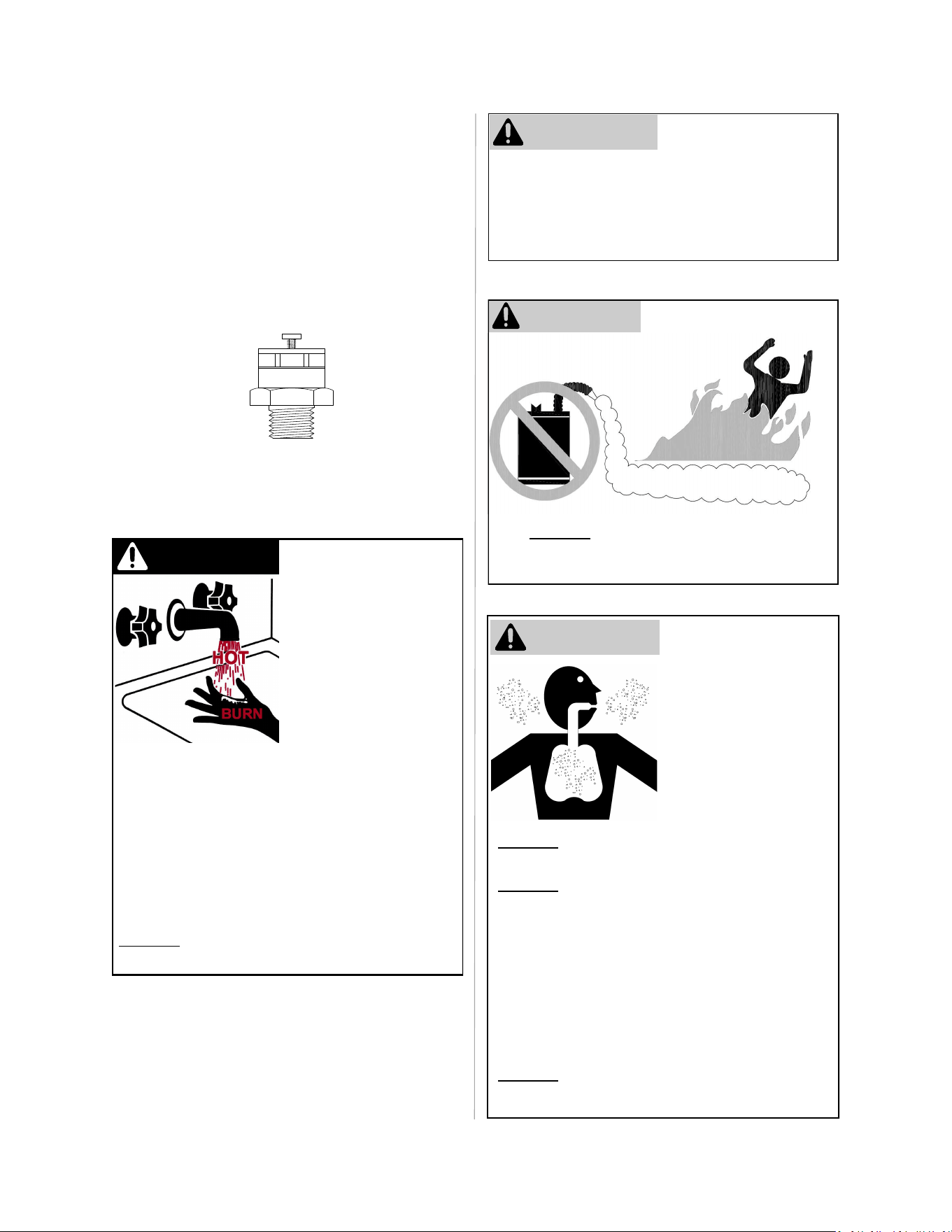
Hot water can be
dangerous, especially for
infants or children, the
elderly, or infirm.
There is hot water scald
potential if the thermostat
is set too high.
Water temperatures over
125ºF (51ºC) can cause
severe burns or scalding
resulting in death.
Hot water can cause first degree burns with
exposure for as little as:
3 seconds at 140ºF (60ºC)
20 seconds at 130ºF (54ºC)
8 minutes at 120ºF (48ºC)
Test the temperature of the water before placing
a child in the bath or shower.
DO NOT leave a child or an infirm person in the
bath unsupervised.
DANGER
CAUTION
• BURN HAZARD. Hot exhaust and vent may
cause serious burns. Keep away from the
water heater unit. Keep small children and
animals away from the unit.
• Hot water outlet pipes leaving the unit can be
hot to touch.
FLAMMABLE
Flammable Vapors
WARNING
FOR YOUR SAFETY
DO NOT store or use gasoline or other
flammable vapors and liquids in the vicinity of this
or any other appliance.
Install vent system per
local and national
codes.
Exposure to carbon
monoxide can cause
serious brain injury or
death. Read and follow
all instructions in this
section.
DO NOT install this water heater above 5,400
ft. (1,646 m).
DO NOT obstruct water heater air intake.
Failure to properly vent this appliance can
result in death, personal injury and/or property
damage.
Gas and carbon monoxide detectors are
available.
Every building should have a carbon monoxide
(CO) alarm in central areas. Check batteries
monthly and replace them annually.
DO NOT operate water heater if flood dam-
aged.
WARNING
Carbon Monoxide
Hazard
• Install the vacuum relief valve per local
codes. Massachusetts 248 CMR Section
10.14 (I) “All potable water pressure tanks
shall be provided with a vacuum relief valve
at the top of the tank that will operate up to a
maximum water pressure of 200 P.S.I.G. and
to a maximum water temperature of 200°F
(93°C).”
Vacuum Relief Valve
(Not Supplied)
If required, install per local code and
valve manufacturers’ instructions.
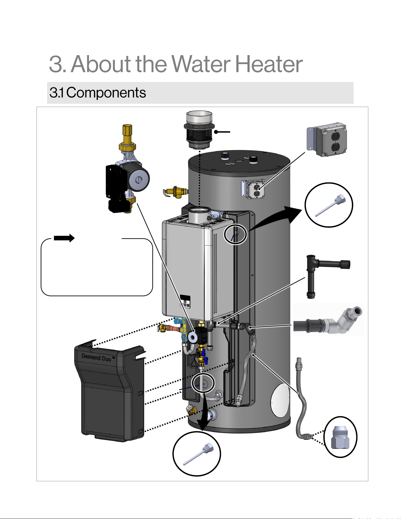
Demand Duo™ R-Series (REC) Installation and Operation Manual 7
Pump
Electric
Conduit
Intake Filter Exhaust
Connector (IFEC)
(Supplied installed)
Dirt Leg
Gas Swivel
Gas Flex Line
Flare Nut
Adapter
Front Cover
The tankless engine is to be used
as a service part only for the
Demand Duo™ R-Series System.
RE is not permitted as a substitute.
REC is not permitted as tankless
only application.
IMPORTANT
Dirt Leg
Upper Tank
Thermistor
Lower Tank
Thermistor
Figure 1
8 Demand Duo™ R-Series (REC) Installation and Operation Manual
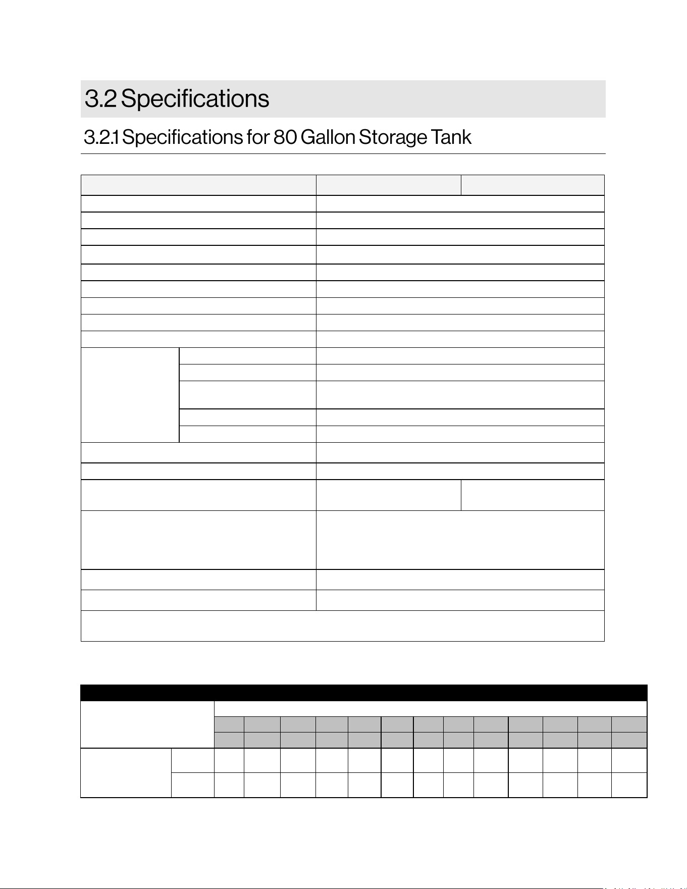
Table 1: Recovery capacies with respect to temperature for 80 gallon storage tank
RECOVERY CAPACITIES
Tank Capacity
U.S. GALLON/HR LITERS/HR AT TEMPERATURE RISE INDICATED
°F 30°F 40°F 50°F 60°F 70°F 80°F 90°F 100°F 110°F 120°F 130°F 140°F
°C 17°C 22°C 28°C 33°C 39°C 44°C 50°C 56°C 61°C 67°C 72°C 78°C
CHS19980RECiN/
CHS19980RECiP
80 U.S.
Gals.
GPH 643 482 386 322 276 241 214 193 175 161 148 138
303
Liters
LPH 2,435 1,826 1,461 1,217 1,044 913 812 730 664 609 562 522
Product Number CHS19980RECiN CHS19980RECiP
Product Descripon Automac Circulang Tank Water Heater
Installaon Type Indoor
Minimum Gas Consumpon Btu/hr (kW/hr) 11,900 (3.5)
Maximum Gas Consumpon Btu/hr (kW/hr) 199,000 (58.3)
Tank Volume 80 Gallons (303 Liters)
First Hour Delivery at 100°F Rise 249 Gallons (942 Liters)
Temperature Seng 120°F (49°C) to 180°F (82°C)
Product Weight 331 lbs. (150 kg)
Noise level 54 dB
System Electrical
Data
Normal 236 W
Standby 1 W
Freeze Protecon
(Tankless)
226 W
Max Current 9.0 A
Fuse Tankless Engine - 10 A
Electric Connecons
Appliance: AC 120 Volts, 60Hz.
Bypass Flow Control
Bypass Servo Control
Gas Supply Pressure
Natural Gas:
4.0 in. wc - 10.5 in. wc
Propane:
8.0 in. wc - 13.5 in. wc
Connecons
Gas Supply Inlet - 3/4 in. MNPT
Hot Water Outlet - 1-1/2 in. MNPT
Cold Water Inlet - 1-1/2 in. MNPT
Ignion System
Direct Electronic Ignion
Maximum Water Supply Pressure
150 PSI
Meets or exceeds energy eciency requirements of ASHRAE 90.1b (current standard), C.E.C. Listed 80%
Recovery Eciency.
Demand Duo™ R-Series (REC) Installation and Operation Manual 9
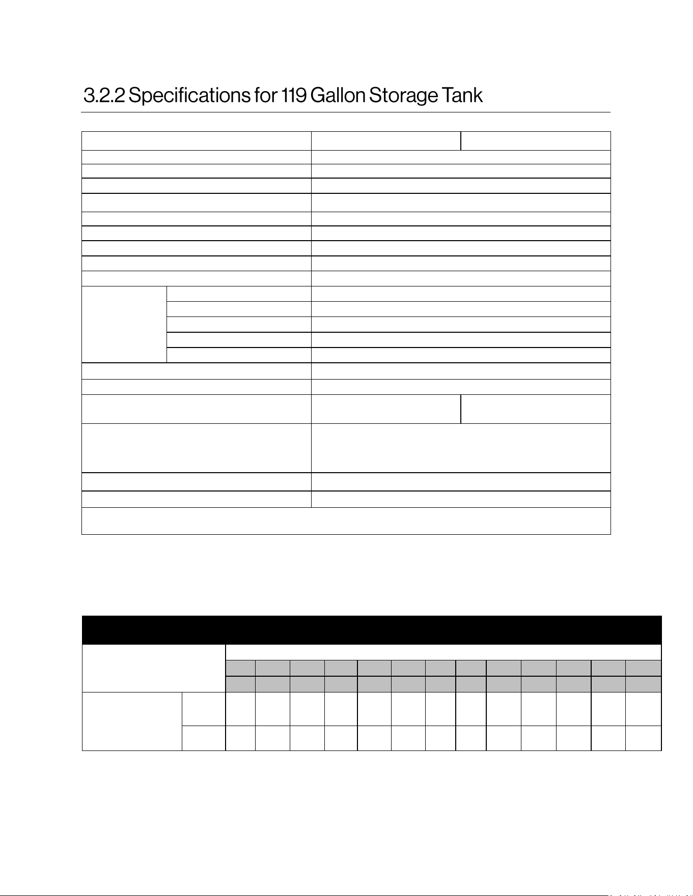
RECOVERY CAPACITIES
Tank Capacity
U.S. GALLON/HR LITERS/HR AT TEMPERATURE RISE INDICATED
°F 30°F 40°F 50°F 60°F 70°F 80°F 90°F 100°F 110°F 120°F 130°F 140°F
°C 17°C 22°C 28°C 33°C 39°C 44°C 50°C 56°C 61°C 67°C 72°C 78°C
CHS199100RECiN/
CHS199100RECiP
119
U.S.
Gals.
GPH 643 482 386 322 276 241 214 193 175 161 148 138
450
Liters
LPH 2,435 1,826 1,461 1,217 1,044 913 812 730 664 609 562 522
Table 2: Recovery capacies with respect to temperature for 119 gallon storage tank
Product Number CHS199100RECiN CHS199100RECiP
Product Description Automatic Circulating Tank Water Heater
Installation Type Indoor
Minimum Gas Consumption Btu/hr (kW/hr) 11,900 (3.5)
Maximum Gas Consumption Btu/hr (kW/hr) 199,000 (58.3)
Tank Volume 119 Gallons (450 Liters)
First Hour Delivery at 100°F Rise
276 Gallons (1046 Liters)
Temperature Setting 120°F (49°C) to 180°F (82°C)
Product Weight 364 lbs. (165kg)
Noise level 54 dB
System Electrical
Data
Normal 236 W
Standby 1 W
Freeze Protection (tankless) 226 W
Max Current 9.0 A
Fuse Tankless Engine - 10 A
Electric Connections
Appliance: AC 120 Volts, 60Hz.
Bypass Flow Control Bypass Servo Control
Gas Supply Pressure
Natural Gas:
4.0 in. wc - 10.5 in. wc
Propane:
8.0 in. wc - 13.5 in. wc
Connections
Gas Supply Inlet - 3/4 in. MNPT
Hot Water Outlet - 1-1/2 in. MNPT
Cold Water Inlet - 1-1/2 in. MNPT
Ignition System
Direct Electronic Ignition
Maximum Water Supply Pressure
150 PSI
Meets or exceeds energy efficiency requirements of ASHRAE 90.1b (current standard), C.E.C. Listed 80% Recovery
Efficiency.
10 Demand Duo™ R-Series (REC) Installation and Operation Manual
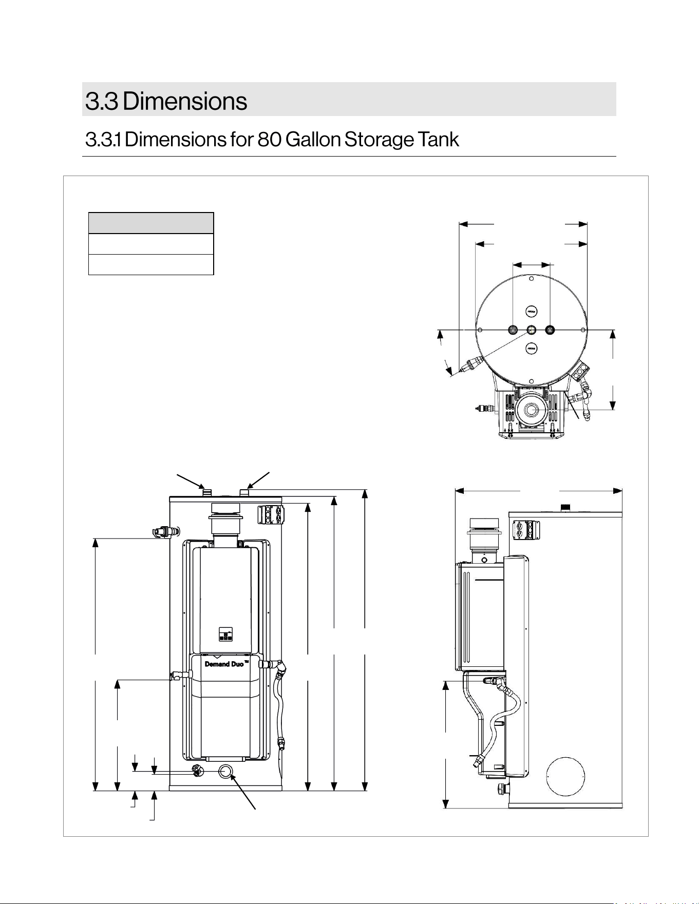
Measurements in drawing
are shown in inches
[millimeters].
Models
CHS19980RECiN
CHS19980RECiP
Side Front
Figure 2
54.3
[1379]
23.8
[605]
4.2 [107]
3.5 [90]
61.9
[1572]
63.3
[1608]
65.25
[1657]
Top
27.7 [703]
ø 24.1 [612]
30°
17.3
[439]
8
[203]
27.2
[691]
35.6
[904]
Cold Inlet
Hot Outlet
Cold Inlet (Oponal)
Demand Duo™ R-Series (REC) Installation and Operation Manual 11
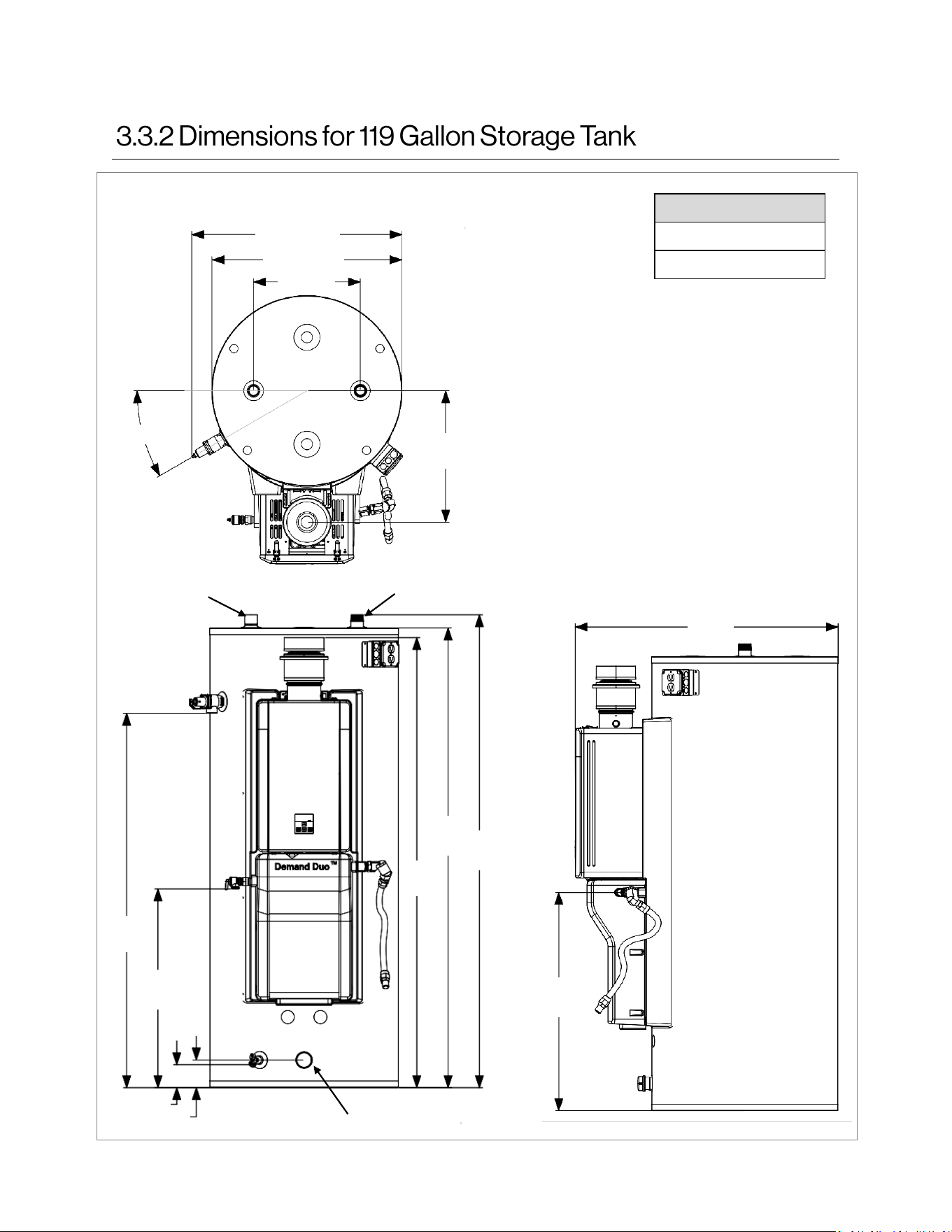
Top
Measurements in
drawing are shown in
inches [millimeters].
Models
CHS199100RECiN
CHS199100RECiP
Front
Side
Figure 3
31.5 [800]
ø 28.5 [724]
30°
19.7
[500]
16 [406]
33.4
[848]
40.2
[1020]
56.5
[1436]
30.0
[762]
3.47 [88]
4.17 [106]
68.0
[1727]
69.4
[1763]
71.4
[1814]
Cold Inlet
Hot Outlet
Cold Inlet (Oponal)
12 Demand Duo™ R-Series (REC) Installation and Operation Manual
Installer qualifications: A trained and qualified
professional must install the appliance,
inspect it, and leak test it before use. The
warranty may be voided due to any improper
installation. The installer should have skills
such as: Gas sizing; Connecting gas lines,
water lines, valves, and electricity; Knowledge
of applicable national, state, and local codes;
Installing venting through a roof; Venting
Category I, Fan-Assisted Appliances per
NFPA 54, CSA B149.1 and local codes. If you
lack these skills contact a licensed
professional.
THIS SECTION IS INTENDED FOR THE
INSTALLER
Topics in this section
• Installation Guidelines
• What You Will Need
• Choose an Installation Location
For installation in commercial applications only.
When installing the water heater, follow these
guidelines:
• The installation must conform with local
codes or, in the absence of local codes, with
the National Fuel Gas Code, ANSI Z223.1/
NFPA 54, or the Natural Gas and Propane
Installation Code, CSA B149.1.
• The appliance, when installed, must be
electrically grounded in accordance with local
codes or, in the absence of local codes, with
the National Electrical Code, ANSI/NFPA 70,
or the Canadian Electrical Code, CSA C22.1.
• The appliance and its main gas valve must
be disconnected from the gas supply piping
system during any pressure testing of that
system at test pressures in excess of 1/2 psi
(3.5 kPa) (13.84 in W.C.).
• Combustion air provided to the appliance
should not be taken from any area of the
structure that may produce a negative
pressure (i.e. exhaust fans, powered
ventilation fans).
• Combustion air must be free of chemicals,
such as chlorine or bleach, that produce
fumes. These fumes can damage components
and reduce the life of your appliance.
• You must follow the installation instructions
and those in section “5. Venting” for adequate
combustion air and exhaust.
• If a water heater is installed in a closed water
supply system, such as one having a backflow
preventer in the cold water supply line, means
shall be provided to control thermal expansion.
Contact the water supplier or local plumbing
inspector on how to control thermal expansion.
• Should overheating occur or the gas supply fail
to shut off, turn off the manual gas shutoff
(control) valve to the appliance.
DO NOT:
• DO NOT install the Commercial Water Heater
outdoors.
• DO NOT install the appliance in an area where
water leakage of the unit or connections will
result in damage to the area adjacent to the
appliance or to lower floors of the structure.
When such locations cannot be avoided, it is
recommended that a suitable drain pan,
adequately drained, be installed under the
appliance. The pan must not restrict
combustion air flow.
• DO NOT obstruct the flow of combustion and
ventilation air.
• DO NOT use this appliance in an application
such as a pool or spa heater that uses
chemically treated water. (This appliance is
suitable for filling large or whirlpool spa tubs
with potable water.)
• DO NOT use substitute parts that are not
authorized for this appliance.
Demand Duo™ R-Series (REC) Installation and Operation Manual 13
• Commercial Hybrid System
• Temperature and Pressure Relief Valve
(pre-installed on Tank)
• Pressure Relief Valve (PRV) (pre-installed on
Tankless Water Heater)
• Intake Filter Exhaust Connector (IFEC)
• Gas Flex/Union
• Drip leg (pre-installed on Tankless Water
Heater)
• B-Vent Offset Adapter
When selecting an installation location, you must
ensure that clearances will be met and vent
length meets the requirements of ANSI Z223.1/
NFPA 54, and/or CSA B149.1. Consider the
installation environment and water quality.
Requirements for the gas line, water lines, and
electrical connection can be found in their
respective installation sections of this manual.
• Pipe Wrenches (2)
• Adjustable pliers
• Screwdrivers (2)
• Wire Cutters
• Gloves
• Safety Glasses
• Level
• Soap or gas leak detector solution
• Approved venting (6 in. B-Vent or greater)
• Teflon tape (recommended) or pipe compound
• Pipe insulation
• Gas Valve
• Hot/Cold Isolation Valve
• Hammer drill with concrete bits
• Saw
• Threading machine with heads and oiler
• Core drill with diamond head
• Torch set
• Copper tubing cutter
• Steel pipe cutter
• Heat tape
• Electrical wire and conduit per local code
• PVC glue/cement
• 5/8 in. ID PVC flexible tubing
• 2 conductor 22 AWG wire for controller
• Single gang electrical box
• Wire nuts
• Unions and drain valves
• Drain Pan
• Earthquake strap
This section provides information on the
importance of water quality to the Rinnai
R-Series Commercial Automatic Circulating Tank
Water Heater. The information is intended to
serve as general guidelines only and is not a
complete list of water quality guidelines.
Consideration of care for your water heater
should include evaluation of water quality. The
water must be potable, free of corrosive
chemicals, sand, dirt, or other contaminants. It is
up to the installer to ensure the water does not
contain corrosive chemicals or elements that can
affect or damage the water heater. Water that
contains chemicals exceeding the levels below
can damage the water heater. Replacement of
components due to water quality damage is not
covered by the warranty.
Contaminant Maximum Level
Total Hardness Up to 200 mg/L
Aluminum * Up to 0.2 mg/L
Chlorides * Up to 250 mg/LL
Copper * Up to 1.0 mg/L
Dissolved Carbon Dioxide
(CO2)
Up to 15.0 mg/L
Iron * Up to 0.3 mg/L
Manganese * Up to 0.05 mg/L
pH * 6.5 to 8.5
TDS (Total Dissolved Solids)* Up to 500 mg/L
Zinc * Up to 5 mg/L
* Source: Part 143 National Secondary Drinking
Water Regulations
Table 3: Water Quality Guidelines
14 Demand Duo™ R-Series (REC) Installation and Operation Manual
If you install this water heater in an area that is known
to have hard water or that causes scale build-up, the
water must be treated and may require a more
frequent flushing schedule.
When scale build-up in the heat exchanger begins to
affect the performance of the water heater, a
diagnostic code “LC” will display. Flush the heat
exchanger to prevent damage to it.
This water heater also includes a service indicator
(Service Soon, SS). When selected in the parameter
settings, an SS code will display on the controller
indicating that it is time to flush and service the water
heater. Scale build-up is caused by hard water and can
be accelerated if the water heater is set at a high
temperature.
Rinnai offers Southeastern Filtration’s “ScaleCutter
Water Conditioning System” that offers superior lime
scale prevention and corrosion control by feeding a
blend of control compounds into the cold water supply.
Air surrounding the water heater is used for combustion
and must be free of any compounds that cause
corrosion of internal components. These include
corrosive compounds that are found in aerosol sprays,
detergents, bleaches, cleaning solvents, oil based
paints/varnishes, and refrigerants. The air in beauty
shops, dry cleaning stores, photo processing labs, and
storage areas for pool supplies often contains these
compounds.
The water heater should not be installed in any areas
where the air may contain these corrosive compounds.
DO NOT store or use gasoline or other flammable
vapors and liquids in the vicinity of this or any other
appliance.
Flammable liquids such as cleaning solvents, aerosols,
paint thinners, adhesives, gasoline and propane must
be handled and stored with extreme care. These
flammable liquids emit flammable vapors and when
exposed to an ignition source can result in a fire hazard
or explosion. Flammable liquids should not be used or
stored in the vicinity of this or any other gas appliance.
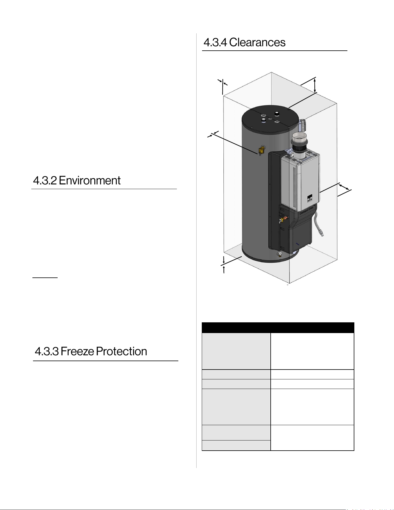
Location Clearance
Top
12 in. (305 mm)
*Clearance for servicing the
anode rods is 54 in. from
the top of the water heater.
Sides 0 in.
Back 0 in.
Front
6 in. (152 mm)
**Clearance for servicing is
24 in. (610 mm) in front of
the water heater.
Intake Filter Exhaust
Connector (IFEC)
6 in. (152 mm)
Single Wall B-Vent
Table 4: Clearances to Combustibles and Non-Combustibles
6 in.
[152 mm]
Front
0 in.
Back
12 in.
[305 mm]
Top
0 in.
Both
Sides
0 in.
Bottom
Figure 4
The water heater and its water lines must be protected
to prevent freezing. Damage due to freezing is not
covered by the warranty. When connected to a 120-volt
power supply and gas is on, the water heater will not
freeze when the outside air temperature is as cold as
22°F (-30°C) when protected from direct wind exposure.
Because of the “wind-chill” effect, any wind or
circulation of air on the water heater will reduce its
ability to protect itself from freezing.In the event of a
power failure and/or gas interruption at temperatures
below freezing, the water heater should manually be
drained of all water to prevent freezing damage. In
addition, drain the water line and pressure relief valve.
Loss of freeze protection may result in water damage
from a burst heat exchanger or water lines that freeze
and break.
Demand Duo™ R-Series (REC) Installation and Operation Manual 15
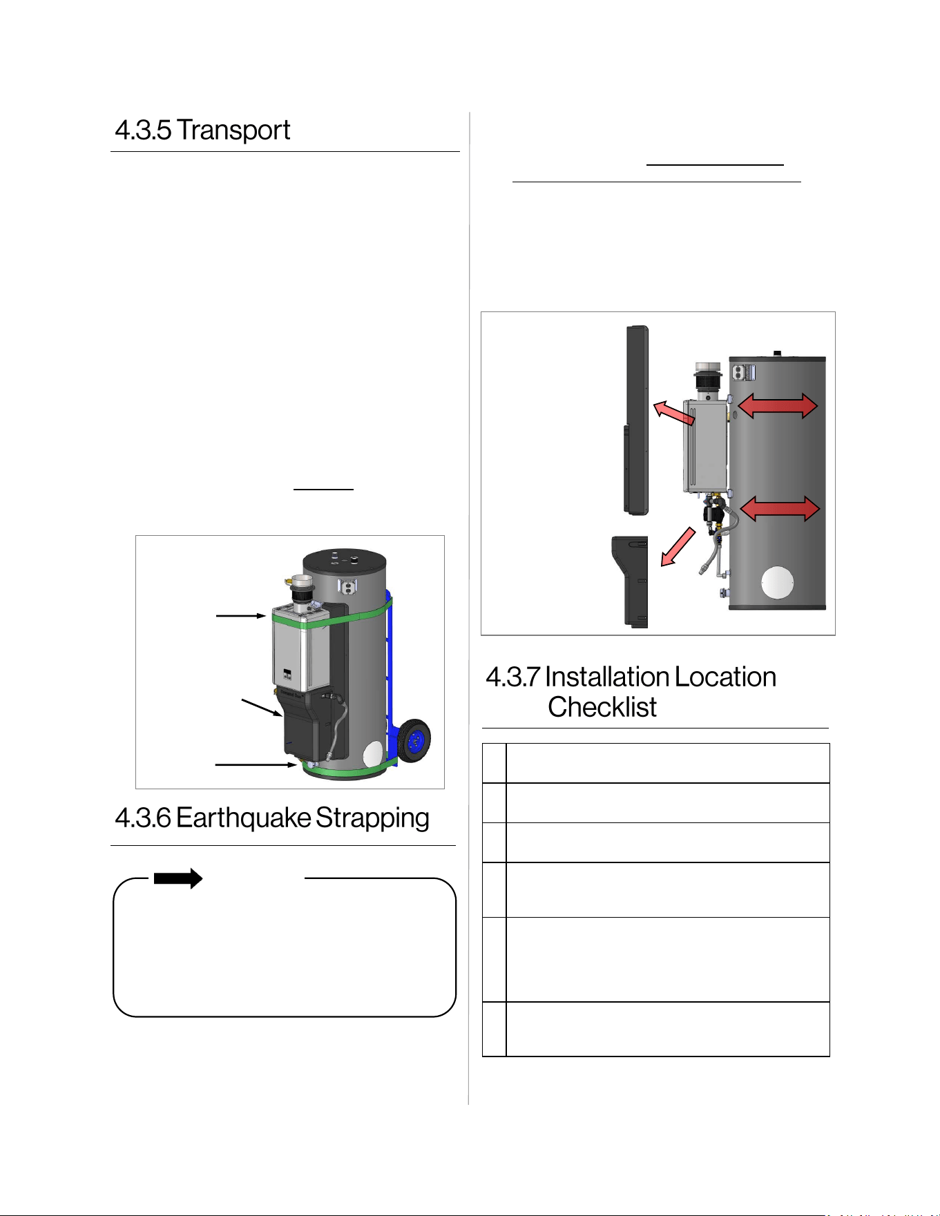
1. Choose the right hand truck to support the
weight and size of the water heater. Refer to
section “3. About the Water Heater” in this
manual for specific weights and dimensions.
2. Use proper lifting techniques to load the
water heater onto the hand truck:
• Position the water heater onto the hand
truck so the weight is evenly balanced and
the tank is touching the rails of the hand
truck.
• Secure the water heater to the hand truck:
− Position STRAP A around the
tankless unit as illustrated below.
− Position STRAP B around the base of
the tank below the LOWER
ENCLOSURE. DO NOT add strap
around the exhaust or vent
connection.
3. Position straps around the Demand Duo tank
per the requirements of California Office of
the State Architect. DO NOT POSITION
STRAPS OVER PIPE, FITTINGS or WIRE.
4. Replace the plastic enclosures. (Modification
of the plastic enclosures may be necessary to
fit the enclosures over the earthquake straps.)
5. Replace the screws around the perimeter of
the plastic enclosures.
IMPORTANT
Product installed in the state of California
must be braced, anchored, or otherwise
secured to avoid motion or falling during an
earthquake. Contact the California Office of
the State Architect located at 1102 Q Street,
Suite 5100, Sacramento, CA 95811 for
instructions.
□
The water heater is not exposed to corrosive
compounds in the air.
□
The water heater location complies with the
clearances.
□
The planned venting termination location
meets the clearances.
□
The water supply does not contain chemicals
or exceed total hardness that will damage the
heat exchanger.
□
The installation must conform with local codes
or, in the absence of local codes, with the Na-
tional Fuel Gas Code, ANSI Z223.1/NFPA 54,
or the Natural Gas and Propane Installation
Code, CSA B149.1.
□
Leave the entire manual taped to the water
heater, or give the entire manual directly to
the owner.
1. Loosen screws along the perimeter of the
plastic enclosures.
2. Remove plastic enclosures.
Strap A
Strap B
Lower
Enclosure
STRAP
Plastic Enclosure
(Side)
Plastic Enclosure
(Bottom)
STRAP
Figure 5
Figure 6
16 Demand Duo™ R-Series (REC) Installation and Operation Manual
• This water heater must be vented vertically to
the outside of the building or structure.
• This water heater is not designed or certified
for side wall horizontal vent terminations.
• All installations must be vented in accordance
with National Fuel Gas Code, ANSI Z223.1/
NFPA 54 - latest edition and the requirements
of state or local codes. In Canada, the water
heater must be vented in accordance with the
National Standard of Canada, and CAN/CSA
B149.1 - latest editions and amendments and
the codes of the local utility or other authority
having jurisdiction.
To prevent possible
personal injury or death
due to asphyxiation, common venting with other
manufacturer’s induced draft appliances is not
allowed.
WARNING
Devices attached to the
vent system intended to
increase system efficiency by reducing the heat
loss of the vent system MUST not be used on this
water heater. Rinnai accepts no liability for
damage or injury if such devices are installed on
the vent system with this appliance.
WARNING
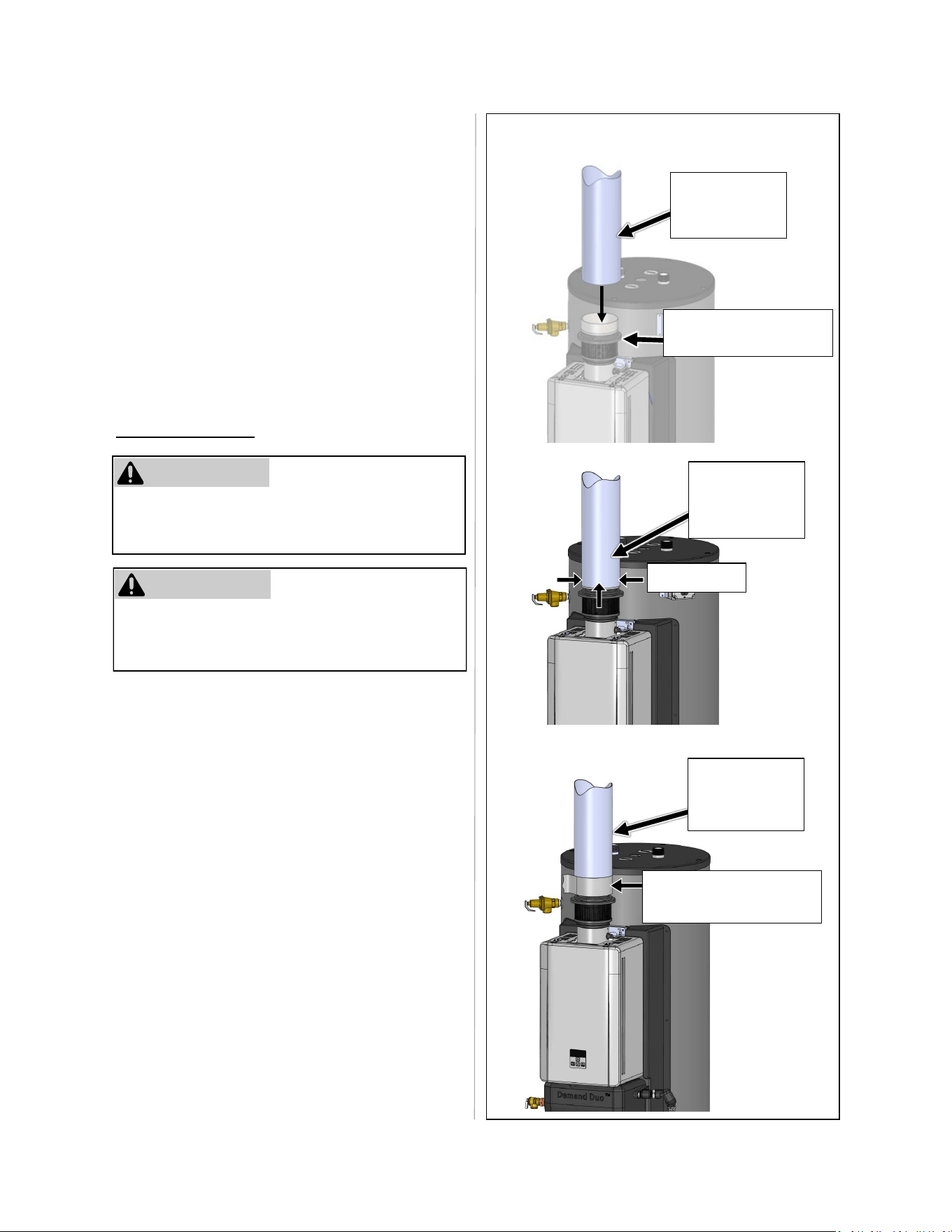
Vent Pipe Assembly: To
avoid damage to the vent
and intake filter exhaust connector (IFEC), pre
drill holes with a 1/8 in. drill bit. Attach the vent to
the vent adapter with #8 screws. Refer to the
“Vent Pipe Assembly” section on the following
page for more information.
WARNING
• All vent (Category I) passing through a
concealed space, an attic or floor, MUST be
Type B double-wall vent and/or Type B double-
wall vent connectors.
• This appliance CANNOT be vented into any
chimney serving an open fireplace or any other
solid fuel burning appliance.
• Use the same diameter Category I connector
or vent as permitted by NFPA 54, ANSI Z223.1
venting tables and/or CSA B149.1.
• The vent must be 6 in. or larger in diameter. It
is not permitted to reduce vent diameter (6 in.).
• Vertical Category I vent or vent connector runs
must be as short and direct as possible.
• Vertical outdoor runs of type B or ANY single -
wall vent below the roof line are NOT
permitted.
• All horizontal vent runs to be sloped up away
from this appliance a minimum of ¼ in. (6 mm)
per foot (21 mm per meter).
Poison carbon
monoxide gas hazard.
If this appliance is replacing a previously
common vented water heater, it may be
necessary to resize the existing chimney liner or
vent to prevent over sizing problems for the other
remaining appliance(s). See codes and/or
standard having jurisdiction. Failure to properly
vent this water heating appliance or other
appliance(s) can result in death, personal injury
and/or property damage.
WARNING
Topics in this section
• Venting Requirements
• Combustion Air Requirements
• Venting Installation Checklist
NOTE
The maximum horizontal length of a
single-wall connector shall be 75% of
the height of the chimney.
If reusing existing venting, it should be
inspected for damage and to ensure it is
appropriate (approved) for this water heater.
To ensure safe and proper operation,
damaged vent components MUST be
replaced before operating the water heater.
IMPORTANT
Demand Duo™ R-Series (REC) Installation and Operation Manual 17
• Existing gas vent or chimney is to be
checked to ensure they meet clearances
and local codes.
• This appliance can ONLY be connected
to a manufactured chimney or vent that
complies with a recognized
standard. Venting into a masonry or
concrete chimney is only
permitted as outlined in the NFPA 54/
ANSI Z223.1, and/or CSA B149.1,
National Fuel Gas Code venting tables. It
is therefore a contractual obligation on the
part of the installer to follow all safe
venting requirements.
Screw x 3
Vent Pipe
(Min. 6 in.
diameter)
Vent Pipe
(Min. 6 in.
diameter)
UL 181A-P/B-FX
Listed Aluminum Tape
Vent Pipe
(Min. 6 in.
diameter)
Intake Filter Exhaust
Connector (IFEC)
The entire vent system (combustion air ducts,
louvers, exhaust vent, etc.) must be checked
periodically for signs of obstruction, rust, or
damage. If damaged components are
observed, they must be repaired or replaced
immediately.
Refer to Figure 7 for the following
instructions.
1. Assemble the field supplied 6 in. B-vent to
the top side of the IFEC.
2. Fasten the 6 in. B-vent to the IFEC with the
provided three (3x) screws.
3. Apply UL 181A-P/B-FX Listed aluminum
tape around the perimeter of the 6 in. B-
vent to properly seal the connection to the
IFEC.
Figure 7
Vent Pipe Assembly: To
avoid damage to the vent
and intake filter exhaust connector (IFEC), pre
drill holes with a 1/8 in. drill bit. Attach the vent to
the vent adapter with #8 screws.
WARNING
Vent Pipe Assembly
Type B listed gas vent
pipe and fittings must be
used. Refer to the vent manufacturer’s
installations instructions for safe and proper
installation of the vent.
WARNING
18 Demand Duo™ R-Series (REC) Installation and Operation Manual
Length:
A vent connector shall be as short as practical
and the appliance located as close as practical to
the chimney or vent. The maximum horizontal
length of the vent connector cannot exceed 75%
of the height of the chimney or vent. Unnecessary
bends should be avoided as to not create
excessive resistance to flow of vent gases.
Single-Wall Vent Connectors:
A single-wall vent connector must not pass
through any interior walls, floors or ceilings. A
single-wall vent connector must not be installed in
attics, crawl spaces or any other confined space
or inaccessible location. Maintain a minimum of 6
in. from combustibles when using single-wall vent
connectors.
Double-Wall, B-Vent:
It is acceptable to pass through walls or partitions
with double-wall, B-Vent.
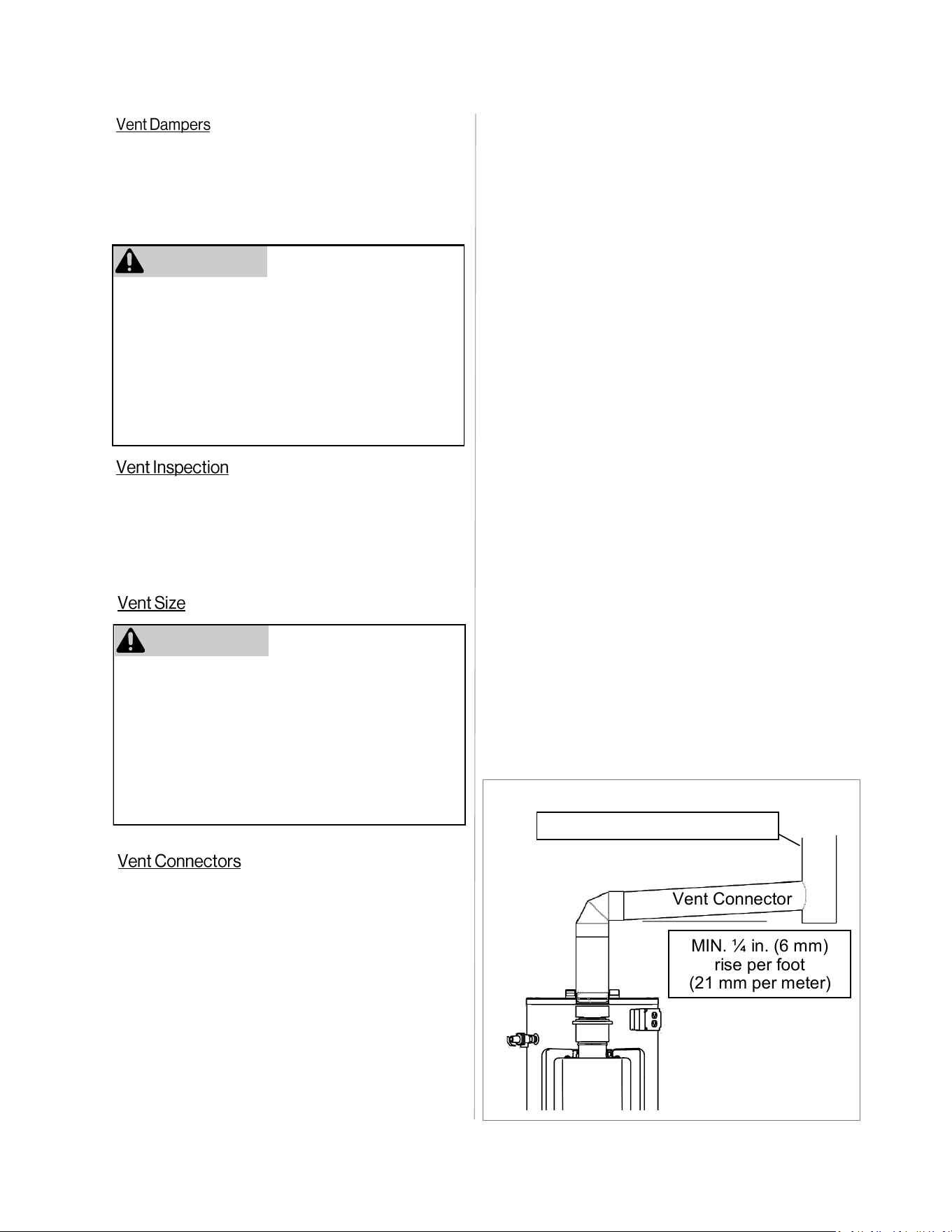
Slope:
Vent connectors must pitch ¼ inch per foot (21
mm per meter) upward (Figure 8).
Inspection:
The entire length of the vent connector shall be
readily accessible for inspection, cleaning and
replacement.
Joints:
Must be fastened by sheet metal screws or other
approved methods.
Support:
Vent connectors must be supported per the vent
manufacturer’s installation instructions to avoid
dips or sags in the vent and maintain the required
clearances.
Vent Connectors are relatively short runs of vent,
connecting the appliance to the chimney or
vertical vent run.
Following is a list of appropriate vent connector
material for use between the water heater and the
chimney:
Type B (B-Vent) Double-wall, U.L. listed vent pipe
Type B (B-Vent) Single-wall, U.L. listed vent pipe
Note the following when installing a vent
connector from the appliance to the chimney or
vertical vent:
Vent dampers must be certified in accordance
with ANSI Z21.68
Before installing any flue damper, consult the
local gas authority and damper manufacturer for
proper installation.
Thermal Operated Vent Dampers: Should NOT
be used with this appliance. This appliance has a
thermal efficiency greater than 80%. This higher
efficiency will result in lower flue gas
temperatures. Such temperatures may be too low
to activate a thermal operated vent damper. Use
of a thermal operated flue damper on this product
may result in spillage of exhaust gases and
ultimately carbon monoxide poisoning.
WARNING
The entire vent system (combustion air ducts,
louvers, exhaust vent, etc.) must be checked peri-
odically for signs of obstruction, rust, or damage.
If damaged components are observed, they must
be repaired or replaced immediately.
CHIMNEY OR LISTED VENT
Vent Connector
MIN. ¼ in. (6 mm)
rise per foot
(21 mm per meter)
Figure 8
This water heater is equipped with a 6 in. vent
adapter and must never be attached to a vent
smaller than 6 in. Certain applications may
require vent diameters greater than 6 in. Consult
your local gas supplier or authority to aid in the
proper vent diameter selection per the
requirements of the vent tables in the current
edition of the National Fuel Gas Code ANSI
Z223.1/NFPA 54, and/or CSA B149.1.
WARNING
Demand Duo™ R-Series (REC) Installation and Operation Manual 19
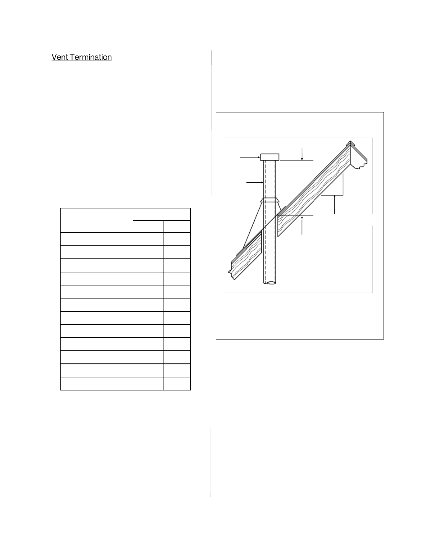
All flue (vent) gases must be directed to the
outdoors of the building or structure and must not
terminate horizontally.
The vent termination shall comply with the
following requirements:
If the listed gas vent is 12 in. (300 mm) or less in
diameter and located not less than 8 ft. (2.4 m)
from a vertical wall or similar obstruction, the
termination must comply with the requirements
stated in Table 5 and Figure 9. If the gas vent is
greater than 12 inches in diameter or located less
than 8 ft. (2.4 m) from a vertical wall or similar
obstruction, the termination must end at a
minimum of 2 ft. (0.6 m) above any portion of a
building within 10 ft. (3.0 m) horizontally.
Roof pitch is x/12
H (minimum) –
Minimum height from
roof to lowest
discharge opening
Roof Slope H (minimum)
ft m
Flat to 6/12 1.0 0.30
Over 6/12 to 7/12 1.25 0.38
Over 7/12 to 8/12 1.5 0.46
Over 8/12 to 9/12 2.0 0.61
Over 9/12 to 10/12 2.5 0.76
Over 10/12 to 11/12 3.25 0.99
Over 11/12 to 12/12 4.0 1.22
Over 12/12 to 14/12 5.0 1.52
Over 14/12 to 16/12 6.0 1.83
Over 16/12 to 18/12 7.0 2.13
Over 18/12 to 20/12 7.5 2.27
Over 20/12 to 21/12 8.0 2.44
B-Vent type gas vent shall terminate at least 5 ft.
(1.5 m) in vertical height above the highest
connected appliance draft hood or flue collar.
Decorative shrouds or coverings shall not be
installed over the gas vent termination unless
listed for use with the specific gas vent and are
installed in accordance with the manufacturer’s
installation instructions.
All gas vents shall extend through the roof
flashing, roof jack, or roof thimble and terminate
with a listed cap or listed roof assembly.
The gas vent shall terminate at least 3 ft. (0.9 m)
above any forced air inlet located within 10 ft.
(3.0 m).
Listed
Gas vent
Listed
Cap
Lowest discharge opening
12
x
Table 5
Example: X = 6, Roof Slope = 6/12, H (Minimum
1.25 . (0.38))
Figure 9
20 Demand Duo™ R-Series (REC) Installation and Operation Manual
Masonry Chimneys shall be built and installed in
accordance with NFPA 211, Standard for
Chimneys, Fireplaces, Vents and Solid Fuel-
Burning Appliances.
Before assembling the vent connector to a
chimney, the chimney must be inspected for signs
of obstruction or damage. If previously used for
solid or liquid fuel burning appliances or
fireplaces, the chimney must be cleaned.
DO NOT connect the vent of this water heater to a
chimney servicing a separate solid fuel burning
appliance.
DO NOT connect the vent of this water heater to a
tile lined masonry chimney. The chimney must be
lined with either B-Vent or a listed chimney lining
system.
Connection to a chimney must be firmly attached,
sealed and must be located above the extreme
bottom of the chimney.
Vertical gas vent must be installed with U.L. listed
type B-vent material in accordance with the
manufacturer’s installation instructions and the
requirements stated in the “National Fuel Gas
Code”, NFPA 54, ANSI Z223.1 and/or CSA
B149.1 (latest edition), and the requirements of
local codes.
Vent should extend in a generally vertical
direction. Any vent angle less than 45 degrees is
considered horizontal. The total horizontal
distance of the vent system plus the horizontal
length of the vent connector must not exceed 75
percent of the vertical height of the vent.
An unused chimney or masonry enclosure may be
used as a chase for the installation of listed B-
vent material.
Common venting of this Category 1, fan-assisted
appliance is permitted. Consult the latest version
of the National Fuel Gas Code (ANSI Z223.1/
NFPA 54). As a Category I appliance, this water
heater can be vented vertically with type B-Vent
systems and lined masonry chimneys. Follow the
National Fuel Gas Code, ANSI Z223.1 and or the
National Gas Installation code and CSA-B149.1
for proper installation practices. If you are unsure
or need assistance in correct application of a
common vent installation consult the local gas
authority for assistance in vent system design.
DO NOT common vent with other manufacturer’s
induced draft appliance.
Altitude
Parameter
Setting
0 - 2,000 ft
(0 - 610 m)
02A
2,001 - 5,400 ft
(610 - 1,646 m)
02b
Table 6: High Altitude
Water heaters covered in this manual have
been tested and approved for installation
at elevations up to 5,400 ft. Failure to
change the parameter settings for high
altitude will result in improper and
inefficient operation of the water heater.
IMPORTANT
Use parameter settings to select the appropriate
altitude for your installation (Table 6).
The default setting for the appliance is 0-2,000
ft. (0-610 m), Parameter Setting 2A.
Refer to section “7. Configure Parameter
Settings” for more information.
Demand Duo™ R-Series (REC) Installation and Operation Manual 21
This water heater requires adequate combustion
air for ventilation and dilution of flue gases.
Failure to provide adequate combustion air can
result in unit failure, fire, explosion, serious bodily
injury or death. Use the following methods to
ensure adequate combustion air is available for
correct and safe operation of this water heater.
Combustion air must be free of acid forming
chemicals such as sulfur, fluorine and chlorine.
These chemicals have been found to cause rapid
damage and decay and can become toxic when
used as combustion air in gas appliances. Such
chemicals can be found in, but not limited to
bleach, ammonia, cat litter, aerosol sprays,
cleaning solvents, varnish, paint and air
fresheners. DO NOT store these products or
similar products in the vicinity of this water
heater.
Corrosive fumes, sometimes found in hair/ nail
salons, spas, or other industries exposed to toxic
fumes, may be released through these vents
when not in operation. Chemicals that are
corrosive in nature should not be stored or used
near the water heater or vent termination.
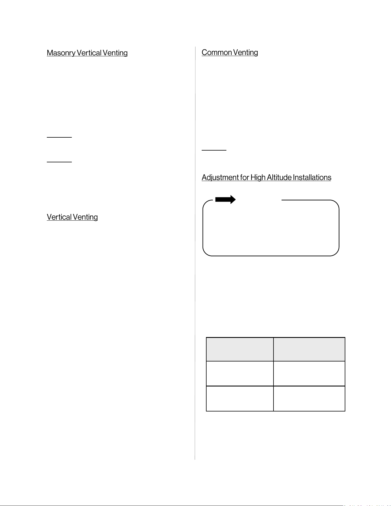
An unconfined space is defined in National Fuel
Gas Code, ANSI Z223.1/NFPA 54, and/or CSA
B149.1 as “a space whose volume is not less
than 50 cubic feet per 1000 Btu/hr (4.8 m3 per
kW per hour) of the aggregate input rating of all
appliances installed in that space. Rooms
communicating directly with the space in which
the appliances are installed, through openings
not furnished with doors, are considered a part of
the unconfined space.” If the “unconfined space”
containing the appliance(s) is in a building with
tight construction, additional outside air may be
required for proper operation. Outside air
openings should be sized the same as for a
confined space.
32 ft.
(9.7 m)
39 ft.
(11.8 m)
32 ft.
(9.7 m)
39 ft.
(11.8 m)
Note: 10 ft. Ceiling
Note: 10 ft. Ceiling
IMPORTANT
Combustion air must be free of corrosive
chemicals. DO NOT provide combustion air
from corrosive environments. Appliance
failure due to corrosive air is not covered by
warranty.
32 . x 32 . x 10 . = 10,240 .
3
50 .
3
x 199,000 Btu/Hr = 9,950 .
3
1,000 .
Above calculaon is an example of the minimum
required volume for Unconned Space
(water heater only).
39 . x 39 . x 10 . = 15,210 .
3
50 .
3
x 299,000 Btu/Hr = 14,950 .
3
1,000 .
Above calculaon is an example of the minimum
required volume for Unconned Space
(water heater and a 100,000 BTU furnace).
Figure 10
22 Demand Duo™ R-Series (REC) Installation and Operation Manual
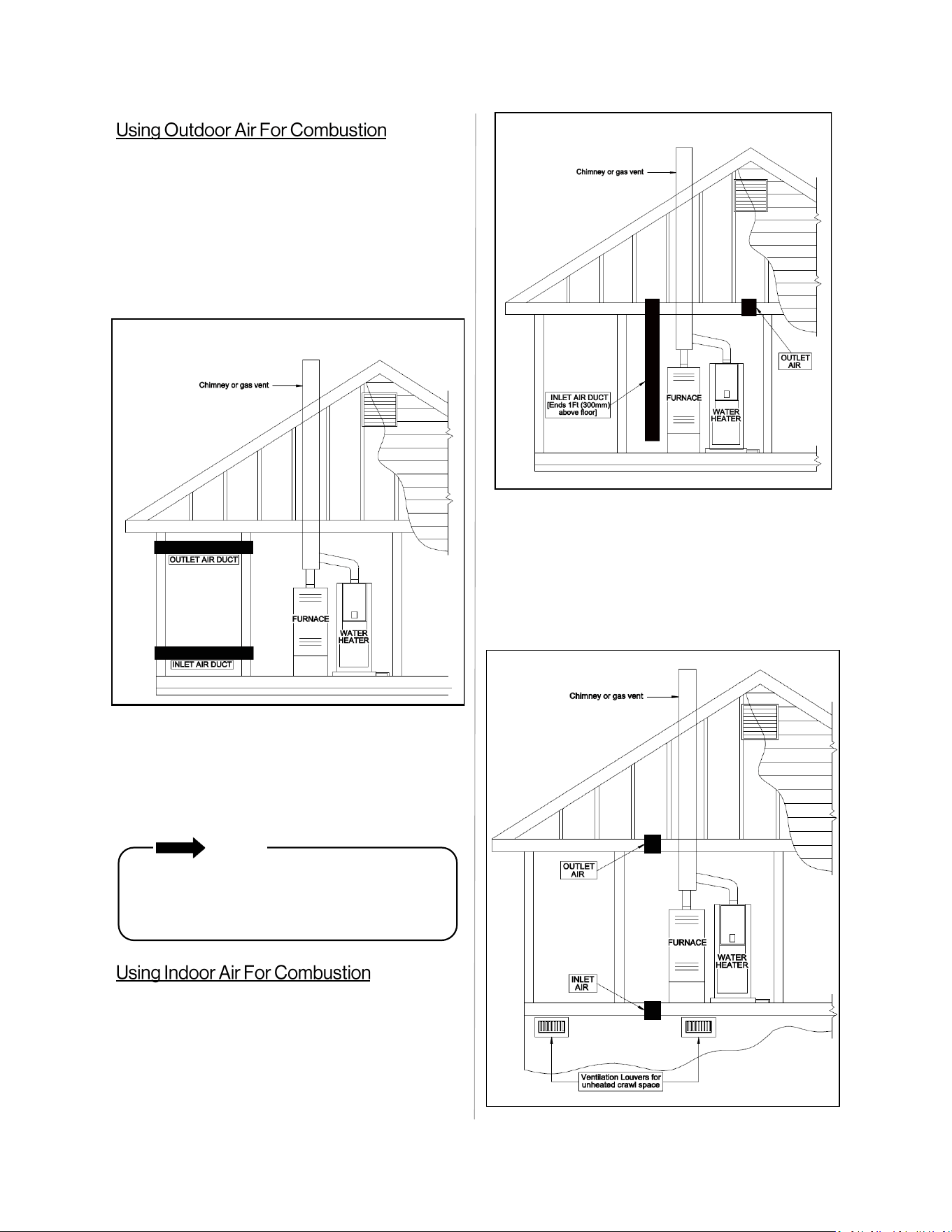
Combustion air provided to the appliance
should not be taken from any area of the
structure that may produce a negative
pressure (i.e. exhaust fans, powered
ventilation fans).
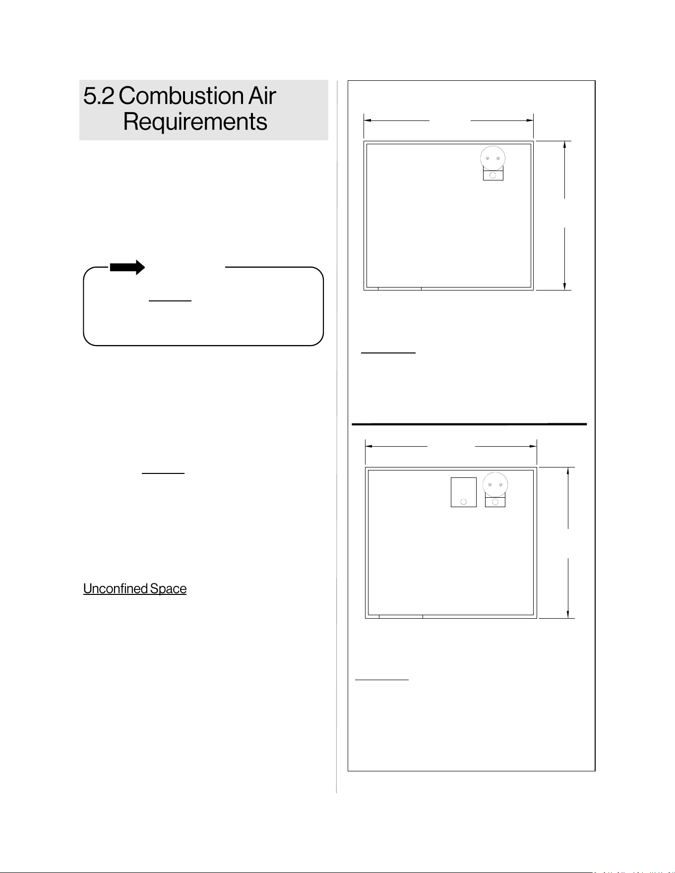
(Small Room, Closet, Alcove, Utility Room, Etc.)
A confined space is defined in the National Fuel
Gas Code, ANSI Z223.1/NFPA 54, and/or CSA
B149.1 as "a space whose volume is less than 50
cubic feet per 1000 Btu/hr (4.8 m3 per kW per
hour) of the aggregate input rating of all
appliances installed in that space." A confined
space must have two combustion air openings.
Size the combustion air openings based on the
BTU input for all gas utilization equipment in the
space and the method by which combustion air is
supplied.
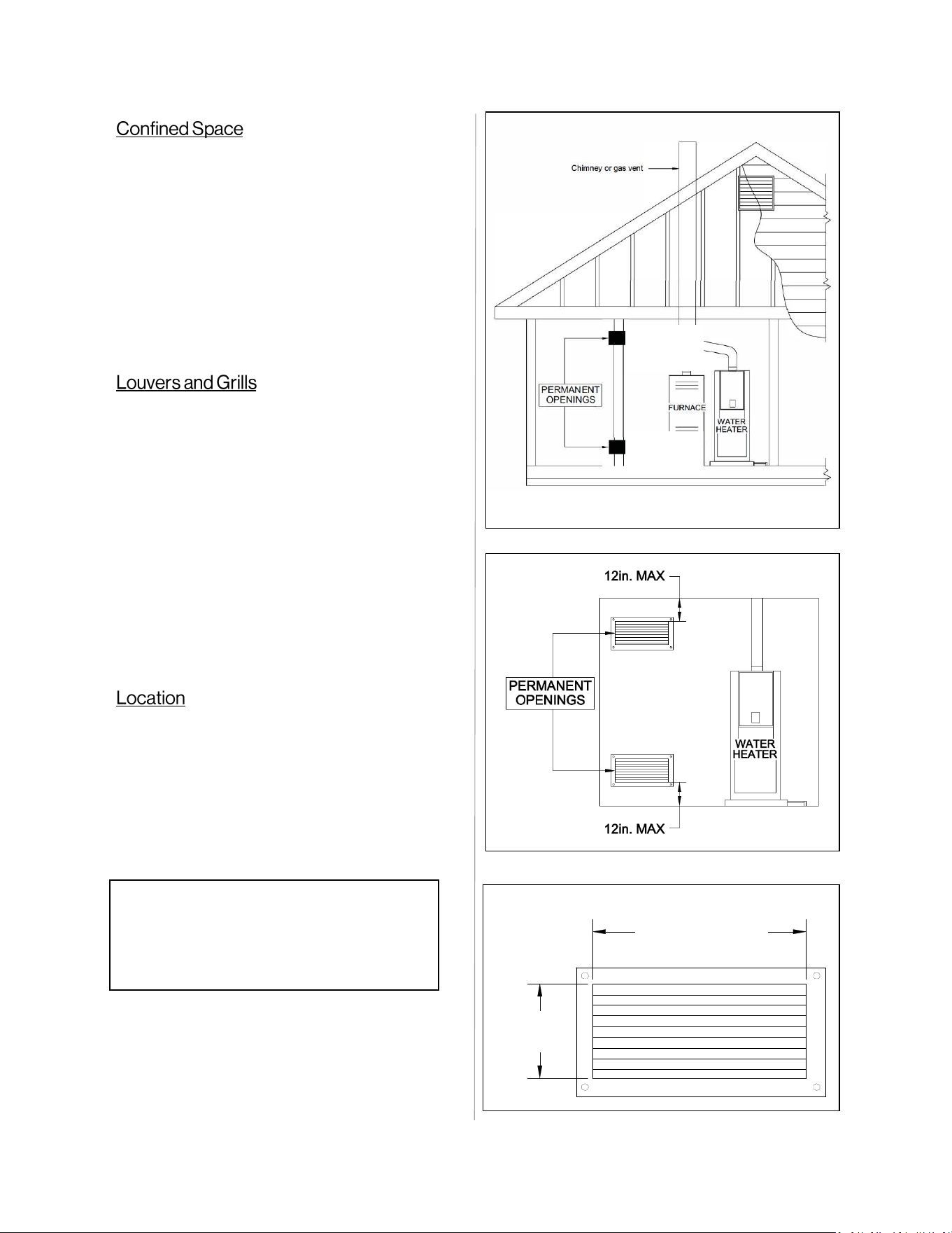
When sizing the permanent opening as illustrated
in Figure 12, consideration must be taken for the
design of the louvers or grills to maintain the
required free area required for all gas utilizing
equipment in the space. If the free area of the
louver or grill design is not available, assume
wood louvers will have 25% free area and metal
louvers or grills will have 75% free area. Under no
circumstance should the louver, grill or screen
have openings smaller than ¼”.
Example:
Free Area = Height x Length x % free area
Wood: 18 in x 24 in x 0.25 = 108 in
2
Metal: 18 in x 24 in x 0.75 = 324 in
2
To maintain proper circulation of combustion air
two permanent openings (one upper, one lower)
must be positioned in confined spaces. The upper
shall be within 12 in. (300 mm) of the top of the
confined space and the lower opening shall be
within 12 in. (300 mm) of the bottom of the
confined space. Openings must be positioned as
to never be obstructed.
24 in. (600 mm)
18 in.
(450 mm)
Note: 8 ft. ceiling
Figure 11
Figure 12
Figure 13
12 in.
(300 mm)
12 in.
(300 mm)
Demand Duo™ R-Series (REC) Installation and Operation Manual 23
When communicating indirectly with the
outdoors through vertical ducts, each opening
shall have a minimum free area of 1 in
2
/4000
Btu/hr (550 mm
2
/kW) of total input rating of all
appliances in the confined space. Combustion
air to the appliance can be provided from a well
ventilated attic or crawl space.
Outdoor air can be provided to a confined space
through two permanent openings, one
commencing within 12 in. (300mm) of the top and
one commencing within 12 in. (300mm) of the
bottom, of the confined space. The openings shall
communicate to the outside by one of two ways:
1. Directly through horizontal ducts
2. Indirectly through vertical ducts
When communicating directly with the
outdoors through horizontal ducts, each
opening shall have a minimum free area of 1
in
2
/2000 Btu/hr (1100 mm
2
/kW) of total input
rating of all appliances in the confined space.
Figure 14
Figure 15
NOTE
If ducts are used, the cross sectional area of
the duct must be greater than or equal to the
required free area of the openings to which
they are connected.
When using air from other room(s) in the
building, the total volume of the room(s) must be
of adequate volume (greater than 50 cubic feet
per 1000 Btu/hr). Regardless of the calculated
free area, the combustion air opening should
never be less than 100 square inches each.
Figure 16
24 Demand Duo™ R-Series (REC) Installation and Operation Manual
□
Verify proper clearances around the vents.
□
Ensure that the Combustion Air Requirements are followed that will provide sufficient combustion air
for the appliance.
□
Ensure you have used the correct venting products for Category 1 and that you have completely
followed the venting manufacturer’s installation instructions and these installation instructions. All
installations must be vented in accordance with National Fuel Gas Code NFPA 54/ANSI Z223.1 -
latest edition and the requirements of state or local codes. In Canada, the furnaces must be vented
in accordance with the National Standard of Canada and CAN/CSA B149.1 - latest editions and
amendments and the codes of the local utility or other authority having jurisdiction.
□
All horizontal vent runs must be sloped up away from the water heater a minimum of 1/4 in. (6 mm)
per foot.
□
Verify that the vent termination clearances are followed.
□
Verify that there is adequate combustion air.
□
Confirm high altitude settings are correct for installation location requirements. See Parameter
Settings Table for more information.
Demand Duo™ R-Series (REC) Installation and Operation Manual 25
MUST DO
• A gas valve must be placed in the gas supply
line to the water heater. Flex line provided with
the appliance can be used as a union.
• Check the type of gas and the gas inlet
pressure before connecting the water heater.
If the water heater is not of the gas type that
the building is supplied with, DO NOT connect
the water heater. Contact the dealer for the
proper unit to match the gas type.
• Check the gas supply pressure immediately
upstream at a location provided by the gas
company. Supplied gas pressure must be
within the limits shown in the “Specifications”
section with all gas appliances operating.
• Before placing the appliance in operation, all
joints including the water heater and gas flex
must be checked for gas tightness by means
of leak detector solution, soap and water, or
an equivalent nonflammable solution, as
applicable. (Since some leak test solutions,
including soap and water, may cause
corrosion or stress cracking, the piping shall
be rinsed with water after testing, unless it has
been determined that the leak test solution is
non-corrosive.)
• Use approved connectors to connect the unit
to the gas line. Purge the gas line of any
debris before connection to the water heater.
• Any compound used on the threaded joint of
the gas piping shall be a type which resists the
action of liquefied petroleum gas (propane/
LPG).
• The gas supply line shall be gas tight, sized,
and so installed as to provide a supply of gas
sufficient to meet the maximum demand of the
heater and all other gas consuming
appliances at the location without loss of
pressure.
WARNING
• A licensed professional must install the gas
supply.
• Confirm the gas type before connecting.
Failure to install correct gas type may result
in injury or damage to the unit.
• Turn off 120v power supply.
• Turn off the gas.
• Gas is flammable. DO NOT smoke or provide
other ignition sources while working with gas.
• DO NOT turn on the water heater or gas until
all fumes are gone.
Topics in this section
• Connect the Gas Supply
• Gas Operating Instructions
• Gas Pipe Sizing Reference Tables
• Connect Electricity
• Checklist for Gas and Electricity
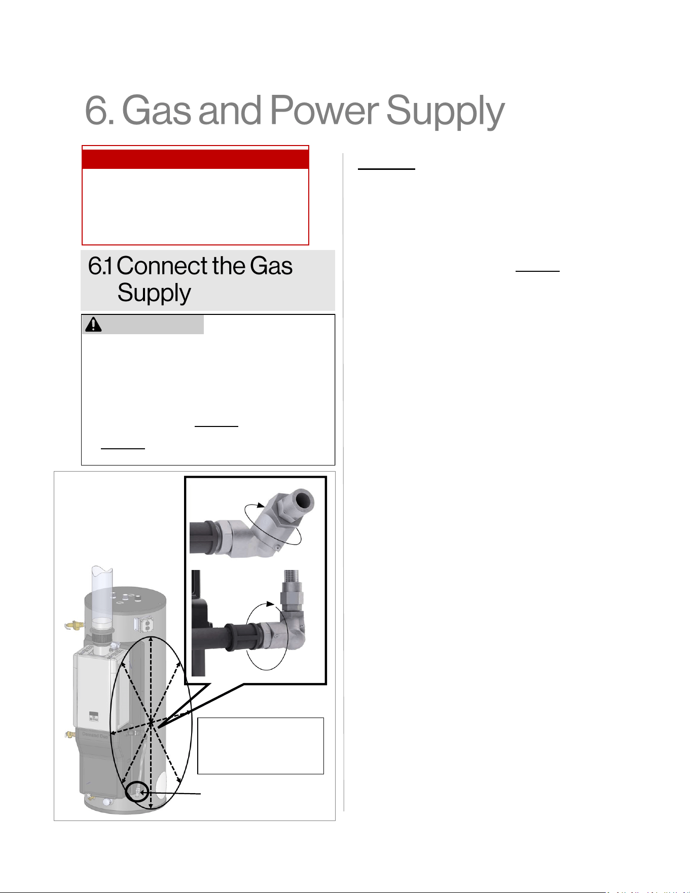
Gas Connection
(3/4 in. MNPT)
The gas swivel and gas
flex line can move in
multiple directions for
installation.
Figure 17
26 Demand Duo™ R-Series (REC) Installation and Operation Manual
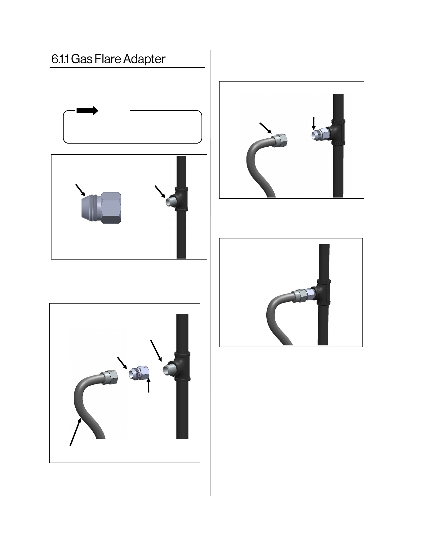
Flare Side
36 in. Gas Flex
3/4 MNPT
Flare Side
3/4 NPT side
1. Apply a pipe sealant approved for gas to
the field-supplied 3/4 MNPT gas line
(Figure 18).
NOTE
DO NOT apply sealant to the parallel
threads on the flare side of the Gas Flare
Adapter.
3. Thread the flare side of the 36 in. Gas Flex
into the flare side of the Gas Flare
Adapter (Figure 20).
5. Leak test ALL gas fittings and assembly
using a leak test solution, soap and water,
or an equivalent nonflammable solution.
6. If leak is identified at the flex connection,
gradually tighten fitting until leak stops.
DO NOT connect gas flex directly to pipe
threads of gas supply pipe or appliance. Install
Gas Flex using only the Gas Flare Adapter
provided.
Flare Side
36 in. Gas Flex
4. Use a backer wrench to tighten all
connections to the recommended torque
value of 62 lbs-ft (Figure 21).
Figure 18
Figure 19
Figure 20
Figure 21
Apply sealant
to connection
2. Thread the 3/4 NPT side of the flare
nut onto the field-supplied 3/4 MNPT
gas line (Figure 19).
Demand Duo™ R-Series (REC) Installation and Operation Manual 27
FOR YOUR SAFETY READ BEFORE OPERATING
A. This appliance does not have a pilot. It is
equipped with an ignition device which
automatically lights the burner. Do not try to
light the burner by hand.
B. BEFORE OPERATING smell all around the
appliance area for gas. Be sure to smell next
to the floor because some gas is heavier than
air and will settle on the floor.
WHAT TO DO IF YOU SMELL GAS
• Do not try to light any appliance.
• Do not touch any electric switch; do not
use any phone in your building.
• Immediately call your gas supplier from a
neighbor’s phone. Follow the gas supplier’s
instructions.
• If you cannot reach your gas supplier, call the
fire department.
C. Use only your hand to push in or turn the gas
control knob. Never use tools. If the knob will
not push in or turn by hand, do not try to repair
it, call a qualified licensed professional. Force
or attempted repair may result in a fire or
explosion.
D. Do not use this appliance if any part has been
under water. Immediately call a qualified
licensed professional to inspect the appliance
and to replace any part of the control system
and any gas control which has been under
water.
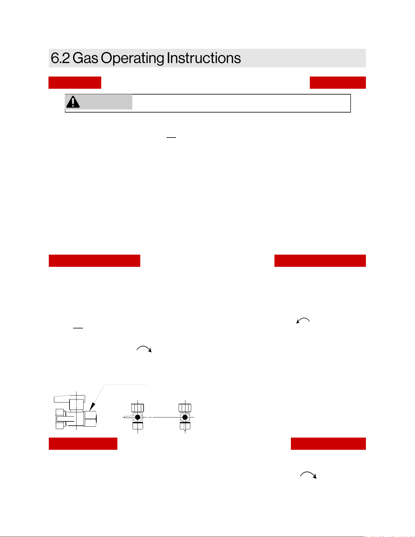
TO TURN OFF GAS TO APPLIANCE
1. Set the thermostat to lowest setting.
2. Turn off all electric power to the appliance
using the ON/OFF button.
3. Locate the manual gas valve on the side of
the heater. Turn the manual valve clockwise
to the full OFF position.
OPERATING INSTRUCTIONS
1. STOP! Read the safety information above.
2. Set the thermostat to lowest setting.
3. Turn off all electric power to the appliance
using the ON/OFF button.
4. This appliance is equipped with an ignition
device which automatically lights the burner.
Do not try to light the burner by hand.
5. Locate the manual gas valve on the side of
the heater. Turn the manual valve clockwise
to the full OFF position.
6. Wait five (5) minutes to clear out any gas.
Then smell for gas, including near the floor. If
you smell gas, STOP! Follow “B” in the safety
information above. If you don’t smell gas, go
to the next step.
7. Turn the manual gas valve counterclockwise
to the full ON position.
8. Turn on all electric power to the appliance
using the ON/OFF button.
9. Set the thermostat to desired setting.
10. Open a hot water tap. If the appliance will not
operate, follow the instructions “To Turn Off
Gas To Appliance” and call your licensed
professional or gas supplier. See manual for
additional information.
CLOSE
Manual Valve
OPEN
If you do not follow these instructions exactly, a fire or explosion may
result causing property damage, personal injury, or loss of life.
WARNING
28 Demand Duo™ R-Series (REC) Installation and Operation Manual
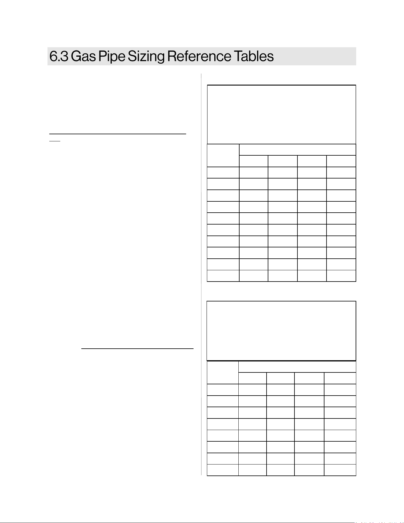
Inlet Pressure: less than 2 psi (55 inches W.C.)
Pressure Drop: 0.3 inches W.C.
Specific Gravity: 0.60
Cubic Feet per Hour (CFH)
Length
Pipe Size (inches)
3/4 1 1 1/4 1 1/2
10 273 514 1,060 1,580
20 188 353 726 1,090
30 151 284 583 873
40 129 243 499 747
50 114 215 442 662
60 104 195 400 600
70 95 179 368 552
80 89 167 343 514
90 83 157 322 482
100 79 148 304 455
Pipe Sizing Table - Natural Gas
Schedule 40 Metallic Pipe
The gas supply must be capable of handling the
entire gas load required at the location. Gas line
sizing is based on gas type, the pressure drop
in the system, the gas pressure supplied, and
gas line type. For gas pipe sizing in the United
States, refer to the National Fuel Gas Code,
NFPA 54, and/or CSA B149.1.
The below information is provided as an exam-
ple. The appropriate table from the applicable
code must be used.
1. For some tables, you will need to determine
the cubic feet per hour of gas required by
dividing the gas input by the heating value
of the gas (available from the local gas
company). The gas input needs to include
all gas products at the location and the
maximum BTU usage at full load when all
gas products are in use.
2. Use the table for your gas type and pipe
type to find the pipe size required. The pipe
size must be able to provide the required
cubic feet per hour of gas or the required
BTU/hour.
Example:
The heating value of natural gas for your loca-
tion is 1000 BTU/FT
3
. The gas input of the
CHS19980REC is 199,000 BTU/HR. Additional
appliances at the location require 65,000 BTU/
hr. Therefore the cubic feet per hour = (199,000
+ 65,000) / 1000 = 264 FT
3
/HR. If the pipe
length is 10 feet then the 3/4 inch pipe size is
capable of supplying 264 FT
3
/HR of natural gas.
Gas Input of all gas products (BTU/HR)
Heating Value of Gas (BTU/FT
3
)
(CFH) =
Length
Pipe Size (inches)
1/2 3/4 1 1 1/4
10 291 608 1,150 2,350
20 200 418 787 1,620
30 160 336 632 1,300
40 137 287 541 1,110
50 122 255 480 985
60 110 231 434 892
80 101 212 400 821
100 94 197 372 763
Pipe Sizing Table - Propane Gas
Inlet Pressure: 11.0 inches W.C.
Pressure Drop: 0.5 inches W.C.
Specific Gravity: 1.50
Capacity in Thousands of BTU per Hour
Schedule 40 Metallic Pipe
Table 7: Pipe Sizing Table - Natural Gas
Table 8: Pipe Sizing Table - Propane Gas
Demand Duo™ R-Series (REC) Installation and Operation Manual 29
• DO NOT use an extension cord or adapter plug with this appliance.
• The water heater must be electrically grounded in accordance with local codes and ordinances or, in
the absence of local codes, in accordance with the National Electrical Code, ANSI/NFPA No. 70.
• The water heater is equipped with a three-prong (grounding) plug for your protection against shock
hazard and should be plugged directly into a properly grounded three-prong receptacle. DO NOT
cut or remove the grounding terminal from this plug. This appliance includes an integrated junction
box for hard wire or three-prong plug.
WARNING
When connecting the power supply, follow these guidelines:
• DO NOT rely on the gas or water piping to ground the water heater. Ground locations are provided
inside the tankless water heater and inside the provided junction box.
• The water heater requires 120 VAC, 60 Hz power from a properly grounded circuit.
• When using the 6 ft. (1.8 m) power cord (included with tankless water heater), plug it into the provided
3 prong 120 VAC, 60 Hz properly grounded outlet or hard wire to the integrated junction box.
• The water heater wiring diagram is located on the inside of the water heater front cover.
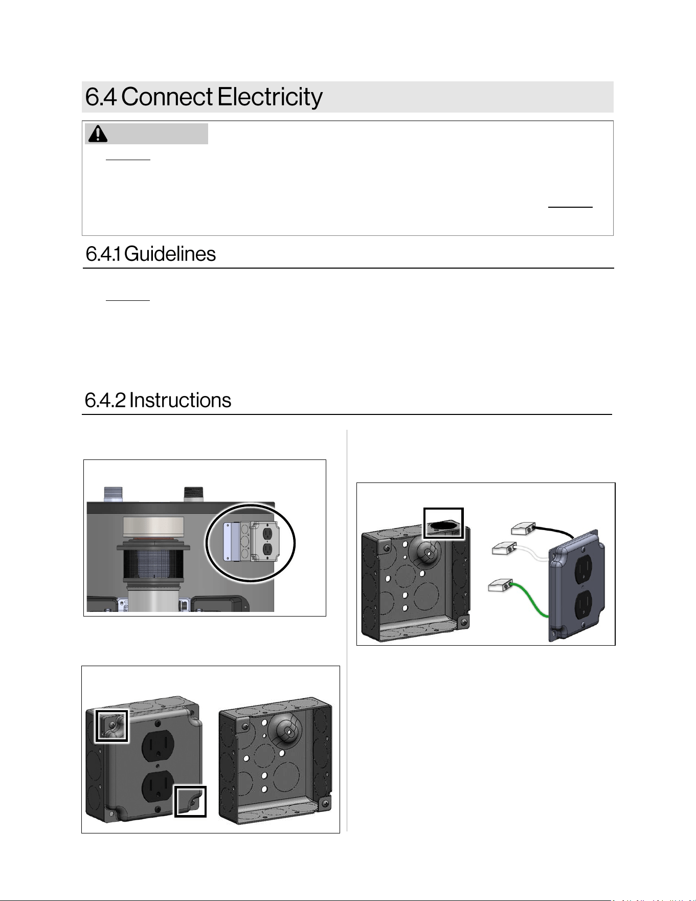
3. Remove the desired knockout along the
perimeter of the electric box for conduit
installation (Figure 24).
2. Remove the two screws around the outlet
cover. Remove the outlet cover and
prewired outlet (Figure 23).
Figure 23
Figure 24
1. Locate the electric conduit on the side of
the water heater (Figure 22).
Figure 22
4. Install conduit into the knockout opening
and pull the green, white and black wires
into the box.
30 Demand Duo™ R-Series (REC) Installation and Operation Manual
□
A manual gas control valve is placed in the
gas line to the water heater.
□
Check the gas lines and connections for
leaks.
□
Confirm that the gas inlet pressure is within
limits.
□
Confirm that the water heater is rated for the
gas type supplied.
□
Confirm that the electricity is supplied from a
120 VAC, 60 Hz power source and is in a
properly grounded circuit.
□
Confirm that an extension cord or an adapter
plug has NOT been used with the water
heater.
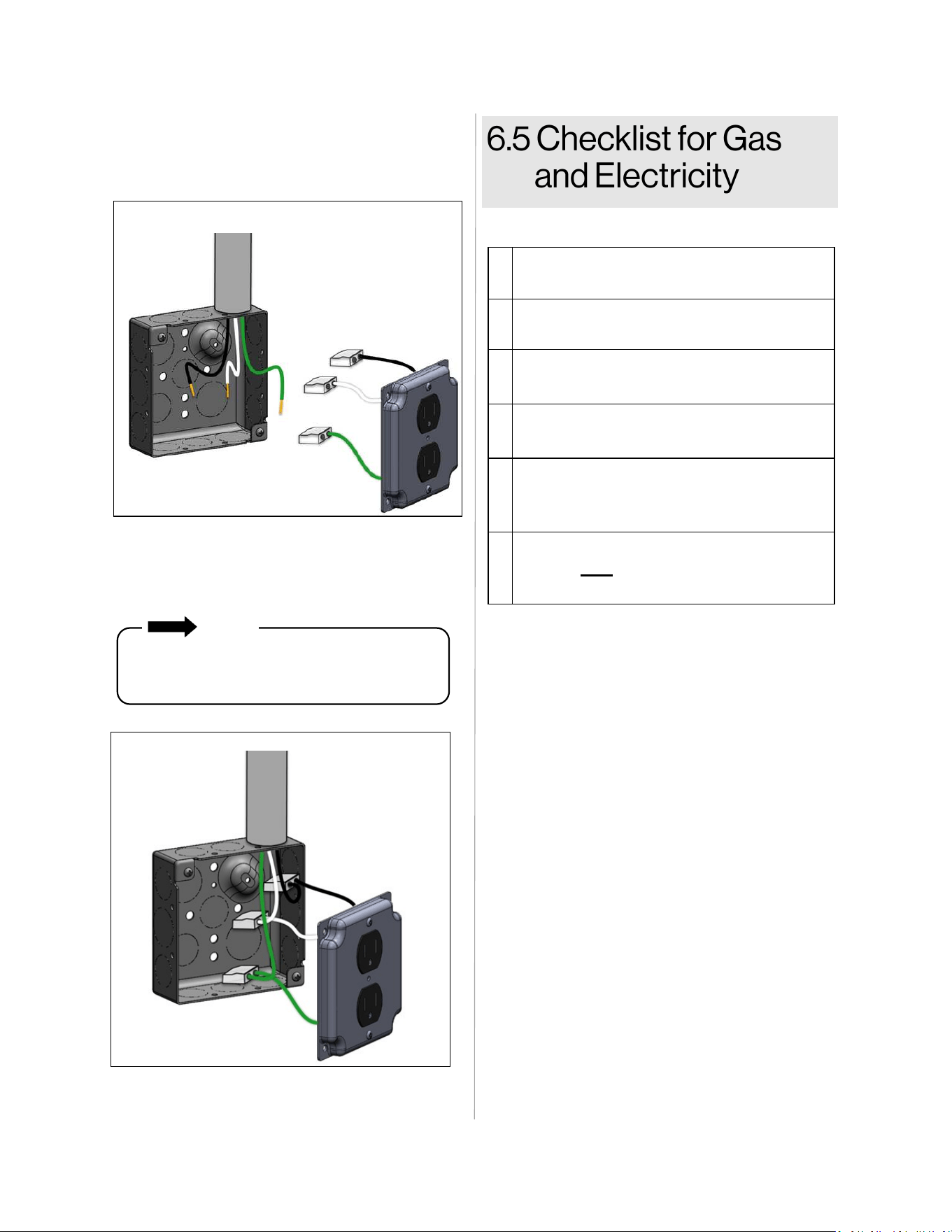
5. Strip the green, white, and black field
supplied wires 1/2 in. Make sure the
conductors are completely bare (Figure 25).
Figure 25
6. Match the wire colors, then grip the wire
firmly and push the conductor into open
port of the push in connector (Figure 26).
Figure 26
Use only one conductor per port. Verify
conductor is fully inserted to the back of
the connector.
NOTE
Demand Duo™ R-Series (REC) Installation and Operation Manual 31
Parameter
Number
Setting Item A B C d
2 High Altitude
0 - 2,000 ft
(0 - 610 m)
2,001 - 5,400 ft
(610 - 1,646 m)
3* Service Soon Disable 0.5 Year 1 Year 2 Years
10** Gas Type LPG NG
50*** Retrofit Application Disable (Default) Enable
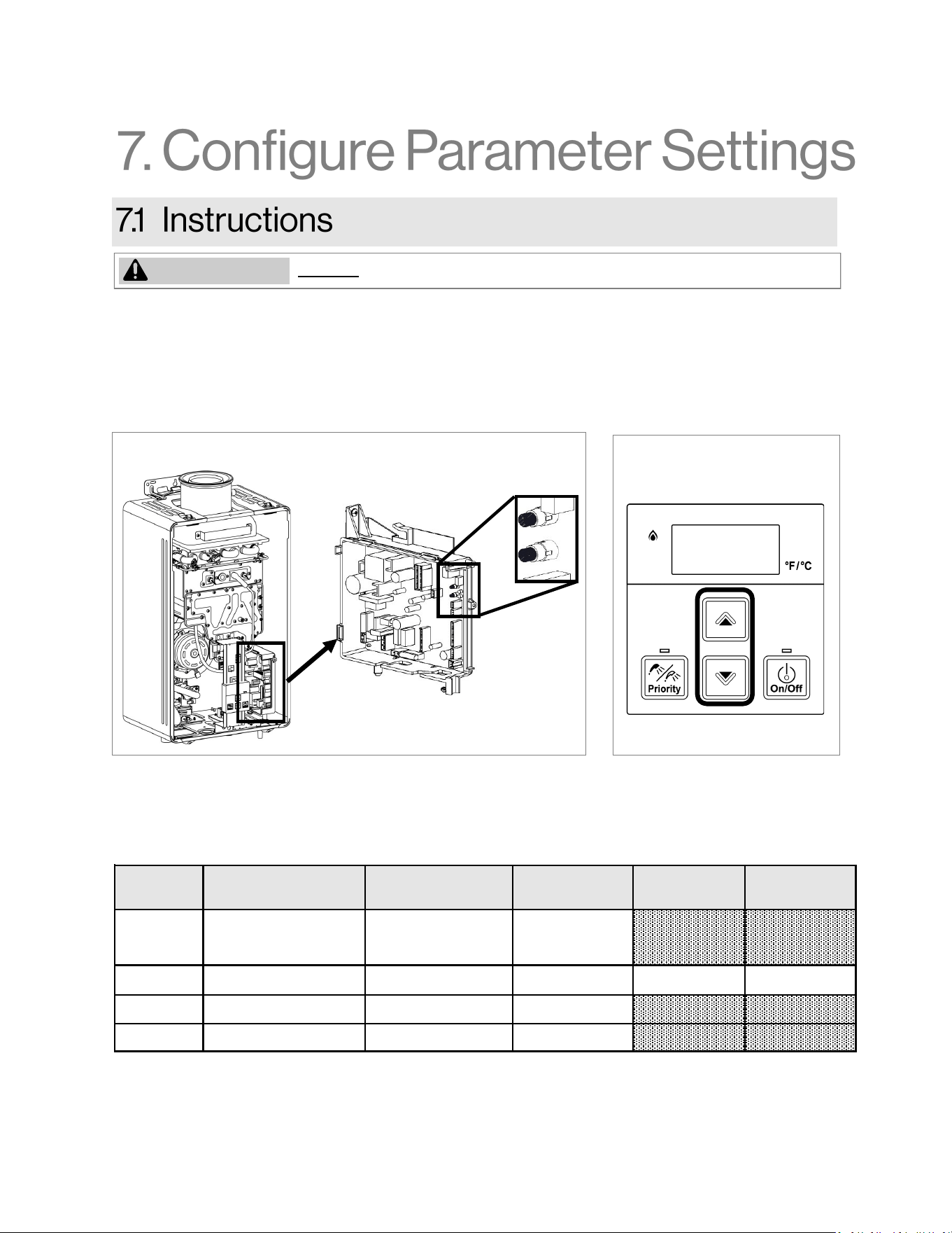
DO NOT adjust parameter settings unless specifically instructed to do so.
WARNING
To adjust the parameters:
1. Locate the PC Board (lower right side of unit).
2. Locate the two push buttons (A and B) on the PC Board.
3. Press the "A" button for 1 second.
4. Use the ▲ (Up) and ▼ (Down) buttons on the controller to select a setting number.
5. Once the desired setting number is selected, use the “On/Off” button on the controller to change the
selection for the setting number.
6. To exit the parameters, press the “A” button for 1 second.
A
B
Figure 27
Figure 28
Table 9: Parameter Settings
* See Section “7.2 Service Indicator (Service Soon, SS)” for more information on Service Soon.
** Factory set. Only used with approved conversion kit.
*** Factory set. Do not adjust unless instructed by Technical Support.
Demand Duo™ R-Series (REC) Installation and Operation Manual 32
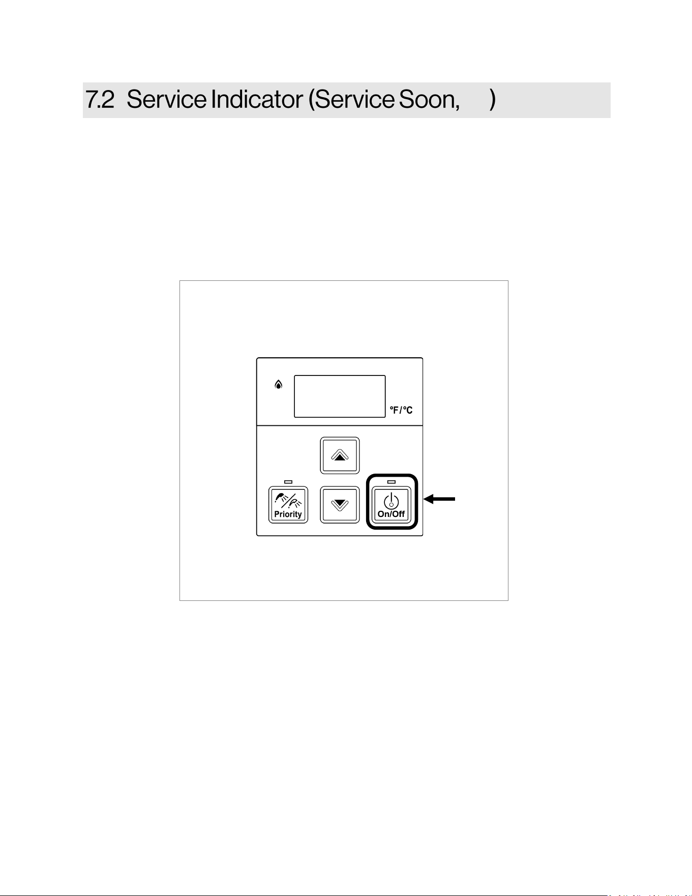
This water heater includes a service indicator (Service Soon, SS). When selected in the parameter
settings, an SS code will display on the controller indicating that it is time to flush and service the water
heater.
• Selection is installers preference based on water conditions or other factors that may influence the
suggested interval of service.
• If Service Soon (SS) appears on the controller display, contact your local service provider to flush
and service the water heater.
• Service Soon will appear again based on the selected service interval.
Figure 29
To Reset Service Soon (SS)
Press the ON/OFF button 5 times.
NOTE: Service Soon (SS) will display on the controller
again when the water heater reaches the interval
selected in the parameter settings.
55
5 times
SS
Demand Duo™ R-Series (REC) Installation and Operation Manual 33
An approved pressure relief valve (PRV)
(preinstalled) is required by the American
National Standard (ANSI Z21.10.3) for all water
heating systems and shall be accessible for
servicing.
DO NOT
• DO NOT plug the PRV and do not install any
reducing fittings or other restrictions in the
PRV line. The relief line should allow for
complete drainage of the valve and the line.
• DO NOT place any other type valve or shutoff
device between the PRV and the water heater.
MUST DO
• The PRV must comply with the standard for
Relief Valves and Automatic Gas Shutoff
Devices for Hot Water Supply Systems ANSI
Z21.22 and /or the standard Temperature,
Pressure, Temperature and Pressure Relief
Valves and Vacuum Relief Valves, CAN1-4.4.
• The PRV must be rated up to 150 psi and to at
least the maximum BTU/hr of the appliance.
• The discharge from the PRV should be
individually piped to the ground or into a drain
system per local codes.
• The PRV must be manually operated once a
year to check for correct operation.
• The PRV is installed near the tankless hot
water outlet according to the manufacturer’s
instructions. DO NOT place any other type
valve or shut off device between the PRV and
the water heater.
Install the Temperature-Pressure Relief (T&P)
Valve according to these instructions. The tank
portion of this system is provided with a
combination T&P Relief Valve. For safe operation
of the water heater, the relief valve(s) must not be
removed from its designated point of installation
or plugged.
An approved T&P Relief Valve is required by the
American National Standard (ANSI Z21.10.3) for
all water heating systems, and shall be accessible
for servicing.
DO NOT
• DO NOT plug the T&P Relief valve and do not
install any reducing fittings or other restrictions
in the relief line. The relief line should allow for
complete drainage of the T&P Relief valve and
the line.
• DO NOT place any other type valve or shut off
device between the PRV and the water
heater.
• DO NOT pipe T&P Relief valve and/or PRV
together into a common pipe.
MUST DO
• The T&P Relief valve must comply with the
standard for Relief Valves and Automatic Gas
Shutoff Devices for Hot Water Supply Systems
ANSI Z21.22 and /or the standard
Temperature, Pressure, Temperature and
Pressure Relief Valves and Vacuum Relief
Valves, CAN1-4.4.
• The T&P Relief valve must be rated up to 150
psi and to at least the maximum BTU/hr of the
appliance.
• The discharge from the T&P Relief valve
should be individually piped to the ground or
into a drain system to prevent exposure or
possible burn hazards to humans or other
plant or animal life. Follow local codes. Water
discharged from the relief valve could cause
severe burns instantly, scalds, or death.
• The T&P Relief valve must be manually
operated once a year to check for correct
operation.
Water discharged from the
PRV could cause severe
burns instantly or death from scalds.
WARNING
• If a PRV discharges periodically, this may be
due to thermal expansion in a closed water
supply system. Contact the water supplier or
local plumbing inspector on how to correct this
situation. DO NOT plug the PRV.
Topics in this section
• Pressure Relief Valve Requirements
• Temperature - PRV Requirements
• Typical Installations
• Piping Diagram for Basic Installations
• Piping Diagram for Multiple Unit Installations
• Connect the Water Heater to the Water
Supply
• Plumbing Checklist
34 Demand Duo™ R-Series (REC) Installation and Operation Manual
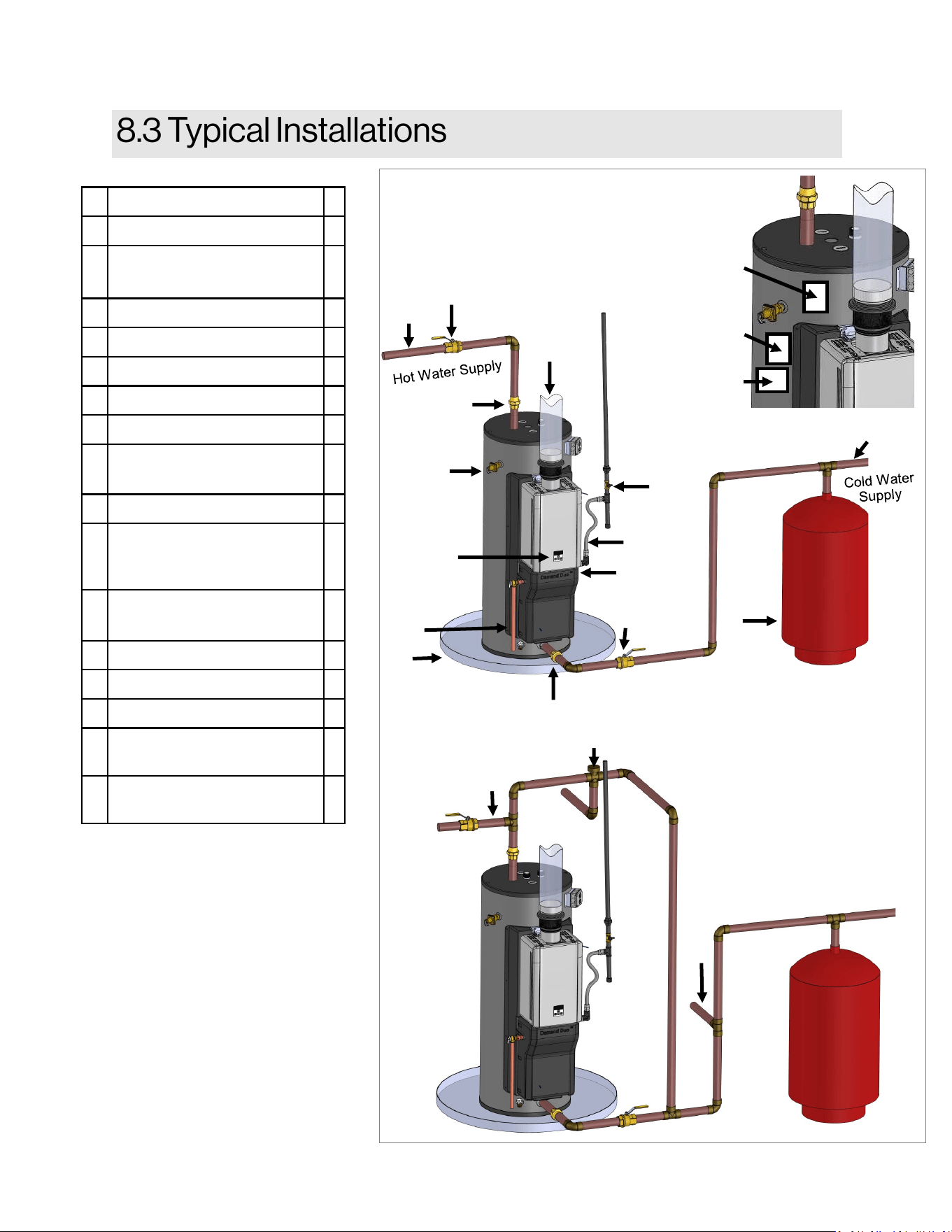
A Hot Water Outlet *
B Hot Water Outlet Valve *
C Temperature-Pressure
Relief Valve
D Cold and Hot Unions *
E Cold Water Supply Valve *
F Cold Water Supply *
G Thermal Expansion Tank *
H 6 in. B-Vent *
I Operation Unit /
Temperature Control
J Drain Pan *
K Pressure Relief Valve
Discharge Pipe (do not
cap, plug, or reduce)
L Drip Leg (Sediment Trap)
(Not Shown)
M Gas Union
N Gas Valve *
O Thermostatic Mixing Valve *
P Non-Tempered Return
Line
*
Q Non-Tempered Supply
Line
*
* Field Supplied
Mixing Valve
Installation
A
B
H
D
C
I
K
J
E
N
M
L
Q
O
P
D
F
G
Figure 30
Demand Duo Serial
Number Label
Tank Serial
Number Label
Temperature &
Pressure Relief
Valve Label
Labels:
Illustration represents bottom
cold water connection. Top
cold connection are optional.
Demand Duo™ R-Series (REC) Installation and Operation Manual 35
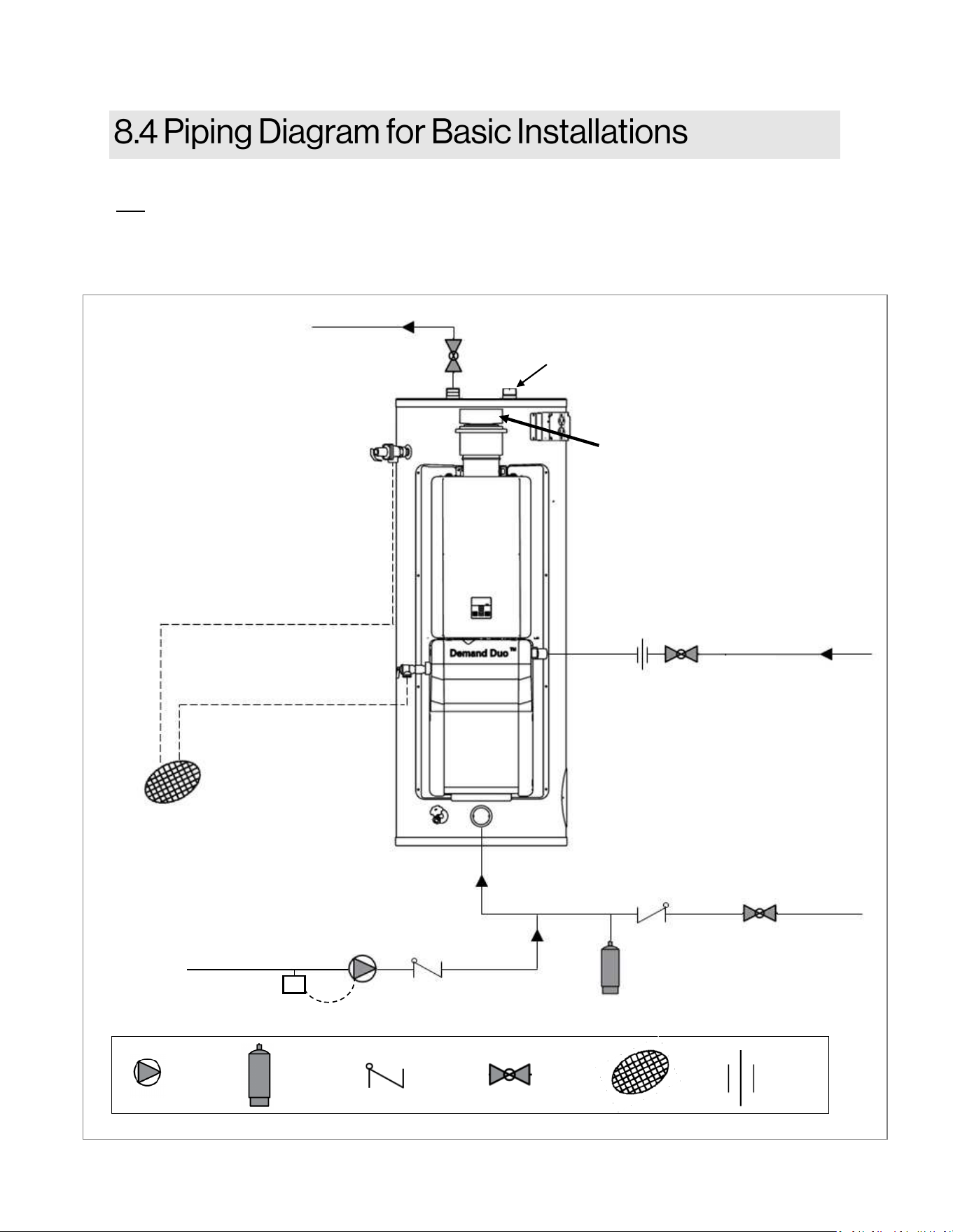
Single Unit Circulation
Note:
Installaon must conform to applicable codes and all requirements listed in this manual. Balancing valves, equivalent piping, pressure gauges,
and temperature gauges are to be used as necessary to ensure proper ow between units.
All components shall be selected for the pressure and temperature rang of the installaon.
Gas Supply
Cold Water Supply
Tankless PRV
Tank T&P
Pipe T&P to Open Drain
Hot Water Supply Line
Building
Circulation
Pump
Building Hot Water
Return Line (Optional)
6 inch. B-Vent
Circulation
Pump
Expansion
Tank
Check
Valve
Ball
Valve
Drain
Union
Figure 31
Cold Inlet (Oponal)
A
Aquastat
10°F < Water Heater
Set Point
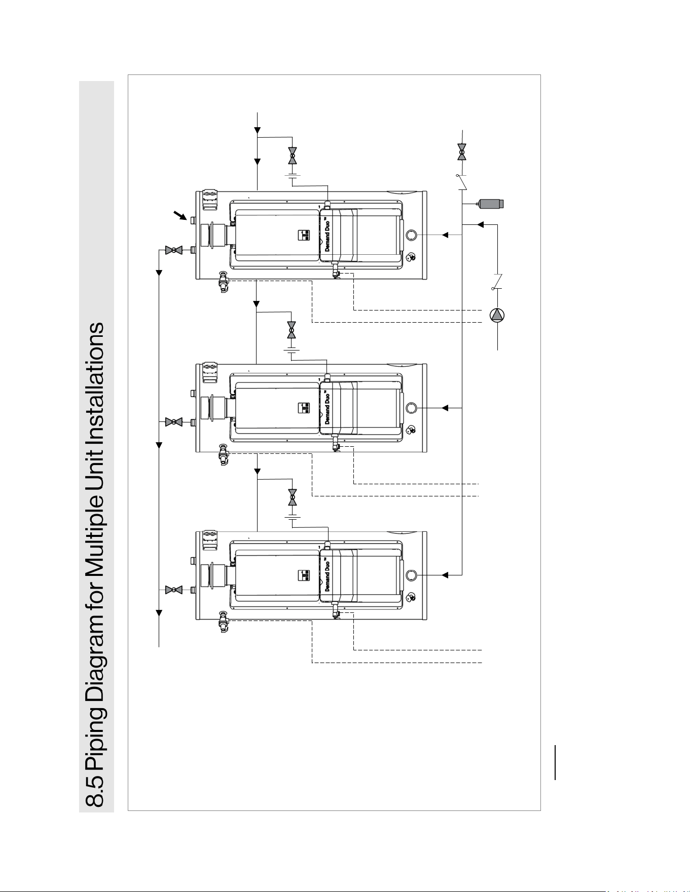
36 Demand Duo™ R-Series (REC) Installation and Operation Manual
Notes:
• Installation must conform to applicable code and all requirements listed in the installation manual. Balancing valves, equivalent piping,
pressure gauges, and temperature gauges are to be used as necessary to ensure proper flow between units.
• Common venting of this Category 1, fan-assisted appliance is permitted. Consult the latest version of the National Fuel Gas Code (ANSI
Z223.1/NFPA 54, and/or CSA B149.1).
• IMPORTANT; Piping must be completed n parallel (first in / Last out) configuration.
PROPERLY SIZED BUILDING CIRCULATION PUMP
AND HOT WATER RETURN LINE (OPTIONAL)
Additional units can be installed as illustrated.
PIPE EACH T&P AND
PRV TO OPEN DRAIN
Gas Supply
Cold Water Supply
Hot Water Supply Line
Alternate connection
for cold water supply.
Figure 32
Demand Duo™ R-Series (REC) Installation and Operation Manual 37
Water connections to the water heater should
follow all state and local plumbing codes. If this is
a standard installation, refer to section “8.4 Piping
Diagram for Basic Installations.”
1. Use of this layout should provide a trouble-
free installation for the life of the water heater.
Before making the plumbing connections,
locate the COLD water inlet and the HOT
water outlet.
• The COLD water inlet is a 1.5 in. MNPT
fitting on the lower portion of the tank or
at the top right side of the tank. Install a
shut-off valve close to the water heater in
the cold water line.
• The HOT water outlet is a 1.5 in. MNPT
fitting located at the top of the tank. It is
recommended that unions be installed in
the cold and hot water lines so that the
water heater can be easily disconnected,
if servicing is required.
2. When assembling the hot and cold piping,
use a good, food grade pipe joint compound,
and ensure all fittings are tight. It is impera-
tive that open flame is not applied to the inlet
and outlet fittings, as heat will damage or de-
stroy the plastic lined fittings. This will result
in premature failure of the fittings, which
is not covered by the warranty.
DO NOT OPERATE THIS WATER HEATER
UNLESS IT IS COMPLETELY FULL OF
WATER. To prevent damage to the water heater,
all air must be relieved from the system and a hot
water fixture must be flowing water before the
water heater is plugged in and turned on. If air is
not relieved, then pump may not operate
properly.
To ensure safe and effective operation of the
water heater, use the following filling procedure.
To fill the water heater:
WARNING
DO NOT OPERATE THIS WATER HEATER
UNLESS IT IS COMPLETELY FULL OF
WATER.
1. Ensure the drain valve located at the bottom
of the tank is closed.
2. Open the nearest hot water fixture in the
plumbing system.
3. Open the cold water supply valve to the water
heater.
4. Keep the hot water fixture open until the tank
is filled and constant flow is obtained at the
fixture.
5. Check water heater connections and
plumbing system for damage or leaks. Repair
if needed.
□
Ensure that hot and cold water lines are not
crossed to the unit and are leak free.
□
Ensure that a pressure relief valve is installed
with a rating that exceeds the BTU input of
the water heater model. Refer to the rating
plate on the side of the water heater for BTU
input.
□
Clean the inlet water filter by closing the cold
and hot water inlet isolation (shut-off) valves
below the tankless water heater. Put a bucket
under the filter at the bottom of the water
heater to catch any water that is contained
inside the unit. Unscrew the water filter. Rinse
the filter to remove any debris. Install the filter
and open the isolation valves.
□
Ensure any issues regarding water quality
have been properly addressed.
38 Demand Duo™ R-Series (REC) Installation and Operation Manual
□
The water heater is not subject to corrosive compounds in the air. Corrosive fumes, sometimes
found in hair/ nail salons, spas, or other industries exposed to toxic fumes, may be released through
vents when not in operation. Chemicals that are corrosive in nature should not be stored or used
near the water heater or vent termination.
□
The water supply does not contain chemicals or exceed total hardness that will damage the heat
exchanger.
□
Balanced system piping for multiple units.
□
Building recirculation pump is sized correctly.
□
System check valves are installed for recirculation circuit.
□
Clearances from the water heater unit are met.
□
Clearances from the vent termination are met.
□
A manual gas control valve has been placed in the gas line to the water heater.
□
Ensure that a pressure relief valve is installed with a rating that exceeds the BTU input of the water
heater model. Refer to the rating plate on the side of the water heater for BTU input.
□
Clean the inlet water filter by closing the cold and hot water inlet isolation (shut-off) valves. Put a
bucket under the filter at the bottom of the water heater to catch any water that is contained inside
the unit. Unscrew the water filter. Rinse the filter to remove any debris. Install the filter and open the
isolation valves.
□
Check the gas lines and connections for leaks.
□
Visually inspect all connections to the tank and assembly for leaks.
□
Confirm that the gas inlet pressure is within limits.
□
Confirm that the water heater is rated for the gas type supplied.
□
Confirm that the electricity is supplied from a 120 VAC, 60 Hz power source, is in a properly
grounded circuit, and turned on.
□
Verify the temperature controller is functioning properly.
□
Verify that parameter setting 02 is set correctly for your altitude. Maximum altitude is 5,400 ft.
□
Using Diagnostic Code 01 (Reference section “11.1 Diagnostic Codes”), confirm recovery flow rate
is between 3-4 GPM.
□
Verify the system is functioning correctly by connecting your manometer to the gas pressure test
port on the water heater. Operate all gas appliances in the facility at high fire. The inlet gas
pressure at the water heater must not drop below that listed on the rating plate.
□
Install the front panel.
□
Explain to the customer the operation of the water heater, safety guidelines, maintenance, and war-
ranty.
□
The installation must conform with local codes or, in the absence of local codes, with the National
Fuel Gas Code, ANSI Z223.1/NFPA 54, or the Natural Gas and Propane Installation Code, CSA
B149.1.
□
Leave Installation and Operation Manual taped to the water heater, or give both manuals
directly to the owner.
Demand Duo™ R-Series (REC) Installation and Operation Manual 39
If the information in these instructions is not
followed exactly, a fire or explosion may result
causing property damage, personal injury, or
death.
• DO NOT store or use gasoline or other
flammable vapors and liquids in the vicinity of
this or any other appliance.
• Before operating, smell all around the
appliance area for gas. Be sure to smell next
to the floor because some gas is heavier than
air and will settle on the floor.
• WHAT TO DO IF YOU SMELL GAS
− DO NOT try to light any appliance.
− DO NOT touch any electrical switch;
− DO NOT use any phone in your building.
− Immediately call your gas supplier from a
neighbor’s phone. Follow the gas
supplier’s instructions.
− If you cannot reach your gas supplier, call
the fire department.
• Installation and service must be
performed by a qualified installer, service
agency or the gas supplier.
WARNING
Topics in this section
• Safety Precautions
• Control Panel
• Basic Operation Settings
• If you install this water heater in an area that
is known to have hard water or that causes
scale build-up, the water must be treated and/
or the heat exchanger flushed regularly.
Rinnai offers a “Scale Control System” that
provides superior lime scale prevention and
corrosion control by feeding a blend of control
compounds into the water supply. Damage
and repair due to corrosive compounds in the
air is not covered by warranty.
• Keep the air intake location free of chemicals
such as chlorine or bleach that produce
fumes. These fumes can damage
components and reduce the life of your
appliance. Damage and repair due to scale in
the heat exchanger is not covered by
warranty.
WARNING
• Keep the area around the appliance clear
and free from combustible materials,
gasoline, and other flammable vapors and
liquids.
• Always check the water temperature before
entering a shower or bath.
• DO NOT use this appliance if any part has
been under water. Immediately call a
licensed professional to inspect the appliance
and to replace any part of the control system
and any gas control which has been under
water.
• Should overheating occur or the gas supply
fail to shut off, turn off the manual gas control
valve to the appliance.
• DO NOT adjust the parameter settings
unless specifically instructed to do so.
• DO NOT use an extension cord or an
adapter plug with this appliance.
• Any alteration to the appliance or its controls
can be dangerous and will void the warranty.
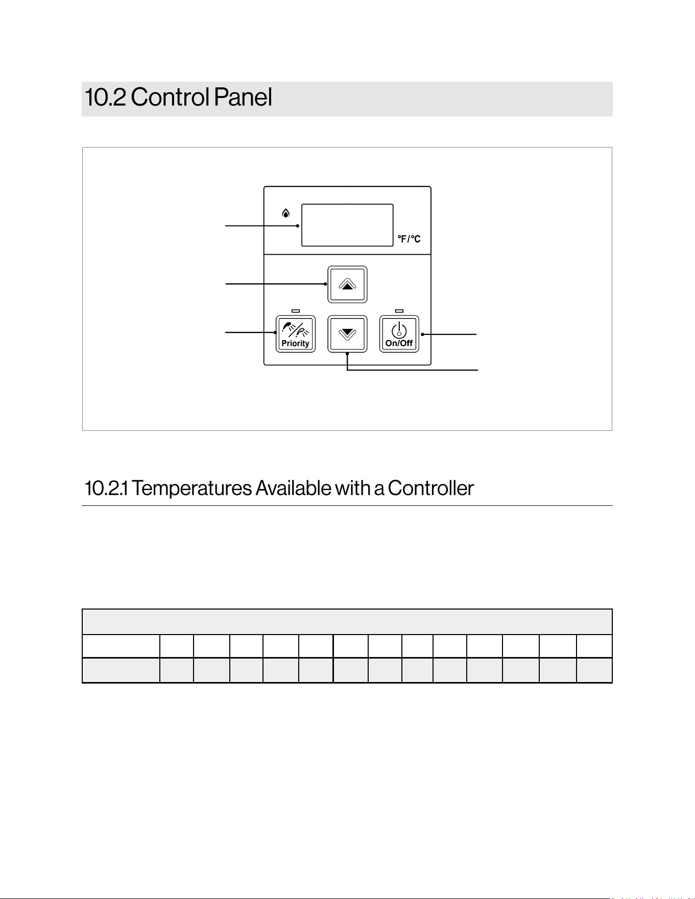
40 Demand Duo™ R-Series (REC) Installation and Operation Manual
A temperature lower than 120°F (49°C) can be obtained at the tap by mixing with cold water.
To change the temperature scale from Celsius to Fahrenheit or vice versa, press and hold the “On/Off”
button for 5 seconds while the water heater is OFF.
Temperature Settings Available
Fahrenheit °F
120 125 130 135 140 145 160 180 150 155 165 170 175
Celsius °C 48.9 51.7 54.4 57.2 60 62.8 71.1 82.2 65.5 68.3 73.9 76.7 79.4
Display
Decreases hot water
temperature
Increases hot water
temperature
Turns the water heater
on or off
Enables controller
when multiple
controllers are used
Table 10: Available Temperature Settings
Figure 33
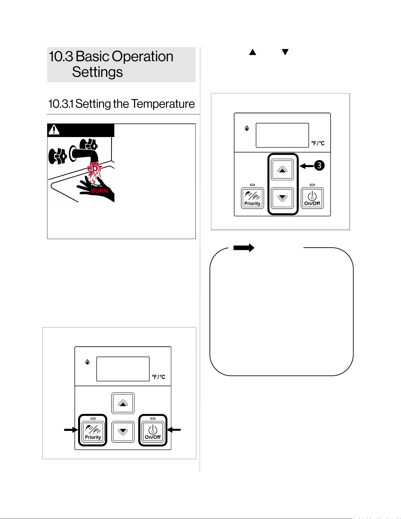
Demand Duo™ R-Series (REC) Installation and Operation Manual 41
• 3 seconds at 140°F
(60°C)
• 20 seconds at 130°F
(54°C)
• 8 minutes at 120°F
(49°C)
Water temperatures over
125°F (52°C) can cause
severe burns or scalding
resulting in death.
Hot water can cause first
degree burns with
exposure for as little as:
Children, disabled, or elderly are at highest risk of
being scalded. Feel water before bathing or
showering.
1. If the water heater is off, press the On/Off
button to turn on.
2. If the Priority light is off, then press the
“Priority” button on the temperature controller.
The green Priority light will glow indicating
that this controller is controlling the
temperature and that the water heater is
ready to supply hot water. (The priority can
only be changed while no hot water is
running.)
DANGER
3. Press the (Up ) or (Down) buttons to
obtain the desired temperature setting.
The temperature can only be changed when
the “In Use” light is off.
IMPORTANT
• Check local codes for the maximum
water temperature setting allowed
when used in nursing homes, schools,
day care centers, and all other public
applications.
• There may be a variation between the
temperature displayed on the
temperature controller and the
temperature at the tap due to weather
conditions or the length of pipe to the
water heater.
• For applications that require less than
120°F, install thermostatic mixing
valve.
❶
❷
❸
Figure 35
Figure 34
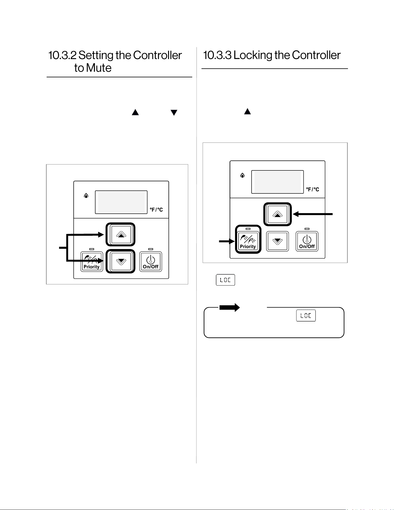
42 Demand Duo™ R-Series (REC) Installation and Operation Manual
To eliminate the beeps when keys are pressed
follow the steps below.
1. Press and hold both the (Up) and
(Down) buttons at the same time until a beep
is heard (approximately 5 seconds). Then,
release both buttons.
To turn on the beeps, repeat the above steps.
1. To lock the controller, press and hold down
the “Priority” button.
2. While holding down the “Priority” button,
press the (Up) button until a beep is heard
(approximately 5 seconds). Then, release
both buttons at the same time.
3. appears in the display indicating the
controller is locked.
NOTE
The display flashes between and
the set temperature to indicate the controller
is locked.
To unlock the controller, follow the above steps.
❶
❶
❷
Figure 36
Figure 37
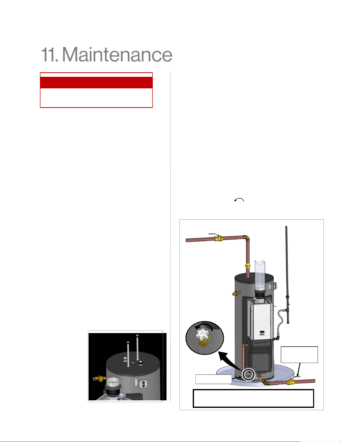
Demand Duo™ R-Series (REC) Installation and Operation Manual 43
Anodes
The storage tank is equipped with two
magnesium anodes designed to extend the life of
the storage tank. Slowly consumed over time, the
anode protects the glass-lined tank from
corrosion. It is strongly recommended to inspect
the anodes every two (2) years. If more than half
of the anodes have been consumed, they should
be replaced.
The longevity of the storage tank can be reduced
when a water softener is introduced to fight hard
water. Sodium salts added by a softener can
make the water extremely conductive; therefore,
the anodes are consumed at a faster rate. In
such conditions, the anodes should be inspected
on a yearly basis.
In certain conditions, the anodes may react with
the water, producing discolored or smelly water.
The most common complaint is hot water that
smells like rotten eggs. This is the result of the
reaction between the anode and hydrogen
sulphide gas dissolved in the water, which is
common in well systems. This issue can usually
be eliminated or reduced by changing the
magnesium anodes to aluminum anodes and by
chlorinating the storage tank and plumbing
system. If the problem continues, special filtration
equipment may be required. Under no
circumstances are the anodes to be removed
from the water heater on a permanent basis.
Removal of the anodes will lead to premature
failure of the water heater and will void the
warranty.
Storage Tank
Drain water through the drain valve at least once
a year. This will remove excess sediment from
the bottom of the tank. This sediment, if allowed
to accumulate, will reduce the efficiency and the
life of the tank.
Draining the Storage Tank
To completely drain the storage tank:
1. Turn the power “OFF” to the system by
disconnecting power to the system. (The
system will not be fully shut down by simply
pressing the power button on the controller.)
2. Close the cold water supply manual shut-off
valve.
3. Connect one end of a garden hose to the
storage tank drain valve and put the other
end next to a free-flowing drain.
4. Open the drain valve by turning the knob
counter clockwise.
5. Open a hot water faucet to allow air into the
system.
Topics in this section
• Diagnostic Codes
Anode
Replacement
Procedure
1. Remove
plastic caps.
2. With 1-1/8
in. socket
wrench,
remove the
anode.
Cold Water
Supply Valve
Drain Valve
Figure 38
Figure 39
Note: The cold water inlet can be installed
either at top or bottom of unit.
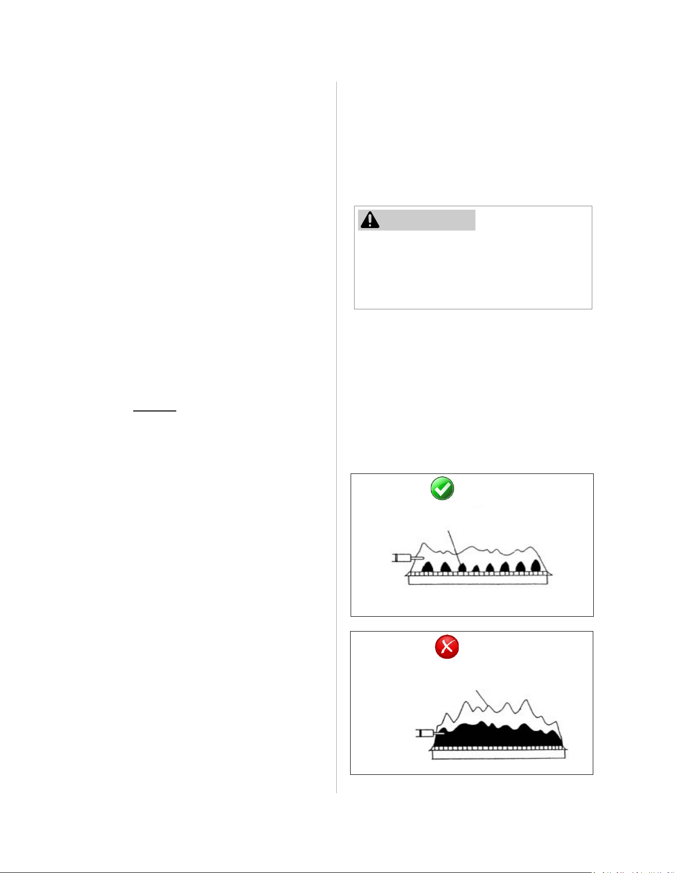
Demand Duo™ R-Series (REC) Installation and Operation Manual 44
Cleaning and Inspecting the
(IFEC) Air Filter
INSPECTION:
• To maintain optimum performance,
periodically inspect the air filter.
• If the air filter appears to have lint and/or
dust build up, follow the cleaning procedure
described below.
• If the air filter appears damaged, contact a
trained and qualified professional for a
replacement air filter assembly.
CLEANING:
1. Power OFF the water heater. Push the “On/
Off” button located on the right-hand side of
the controller. The display will go blank
when the power is off.
2. Vacuum lint or debris from the surface of the
vent screen.
3. Power ON the water heater.
Temperature Controller
Use a soft damp cloth to clean the temperature
controller. DO NOT use solvents.
Lime/Scale Build-Up
Scale build-up is caused by hard water and can
be accelerated if the water heater is set at a
high temperature. Refer to section “11.
Maintenance” (“Flushing the Heat Exchanger”
section). Refer to section “4.3.1 Water Quality
Guidelines” to determine if your water needs to
be treated or conditioned. The water must be
potable, free of corrosive chemicals, sand, dirt,
or other contaminates. It is up to the installer to
ensure the water does not contain corrosive
chemicals, or elements that can affect or
damage the heat exchanger. Water that
contains chemicals exceeding required levels,
affect and damage the heat exchanger.
Replacement of the heat exchanger due to
water quality damage is not covered by the
warranty.
Water Filters
Clean the inlet water filter by closing the cold
and hot water inlet isolation (shut-off) valves.
Put a bucket under the filter at the bottom of the
water heater to catch any water that is contained
inside the unit. Unscrew the water filter. Rinse
the filter to remove any debris. Install the filter
and open the isolation valves.
SATISFACTORY
FRONT VIEW
BLUE FLAME
FLAME
ROD
UNSATISFACTORY
Visual Inspection of Flame
Verify proper operation after servicing. The
burner must flame evenly over the entire surface
when operating correctly. The flame must burn
with a clear, blue, stable flame. See the parts
breakdown of the burner for the location of the
view ports.
The flame pattern should be as shown in the
images below:
Pressure Relief Valves
Operate the pressure relief valve manually once
a year. In doing so, it will be necessary to take
precautions with regard to the discharge of
potentially scalding hot water under pressure.
Ensure discharge has a safe place to flow.
Contact with your body or other property may
cause damage or harm.
WARNING
Testing the pressure relief valve should only
be performed by a trained and qualified
professional. Water discharged from the
pressure relief valve could cause severe
burns instantly or death from scalds.
FRONT VIEW
FLAME
ROD
YELLOW FLAME
Figure 40
Figure 41
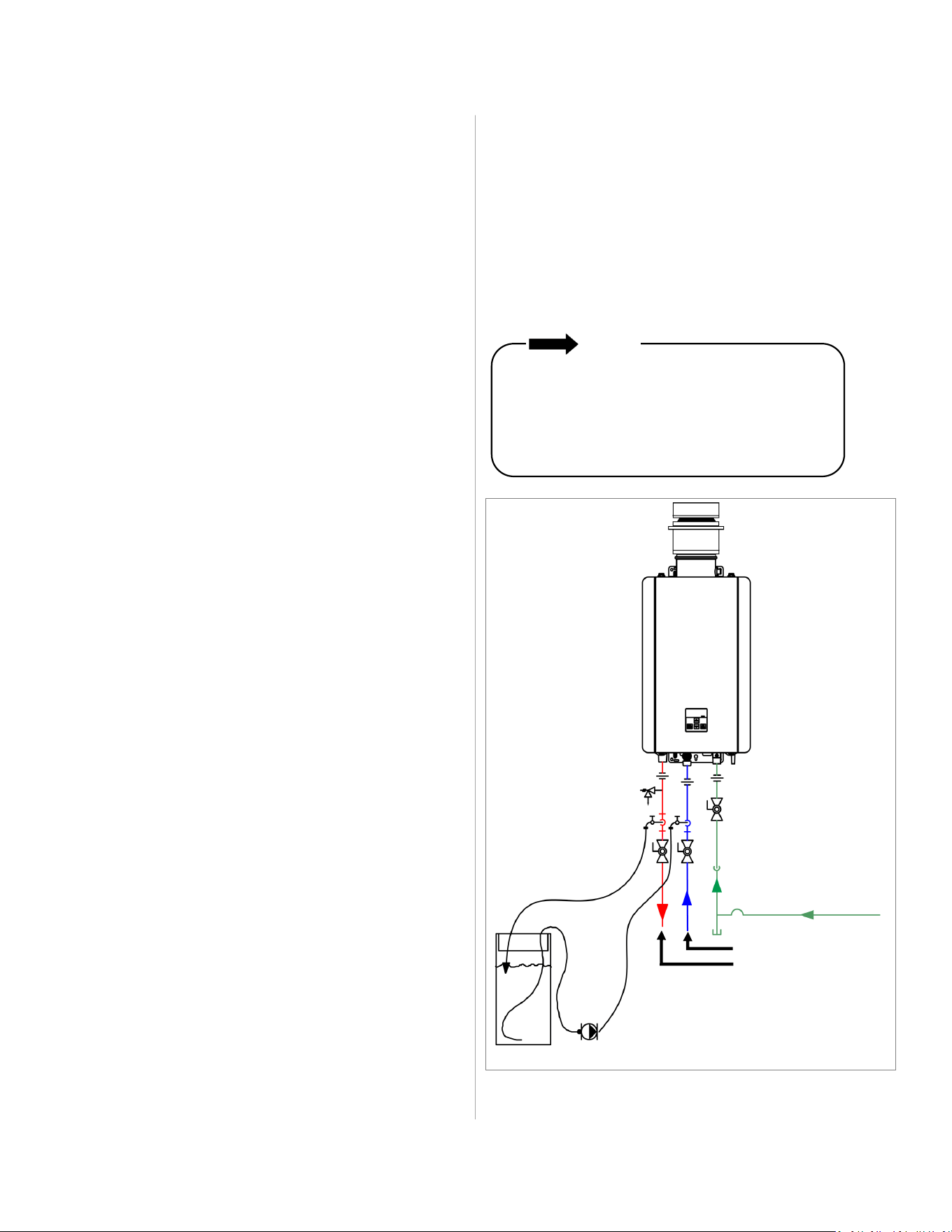
Demand Duo™ R-Series (REC) Installation and Operation Manual 45
Figure 42
Flushing the Heat Exchanger
This water heater includes a service indicated/
reminder (Service Soon, SS). When selected in
the parameter settings, an SS code will display
on the controller indicating that it is time to flush
and service the water heater. An LC diagnostic
code also indicates the unit is beginning to lime
up and must be flushed. Failure to flush the
appliance will cause damage to the heat
exchanger. Damage caused by lime build-up is
not covered by the water heater’s warranty.
Rinnai strongly recommends installation of
isolation valves to allow for flushing of the heat
exchanger.
1. Turn power on at the controller.
2. Disconnect electrical power from the source.
3. Close the shutoff valves on both the hot
water and cold water lines (V3 and V4).
4. Connect pump outlet hose (H1) to the cold
water line at isolation valve (V2).
5. Connect drain hose (H3) to the hot water line
at isolation valve (V1).
6. Pour four gallons of undiluted virgin, food
grade, white vinegar into pail.
7. Place the drain hose (H3) and the hose (H2)
to the pump inlet into the cleaning solution.
8. Open both isolation valves (V1 and V2) on
the hot water and cold water lines.
9. Restore power to the water heater for 20-30
sec. (this will open the water flow servo).
10. Disconnect electric power from the source.
11. Operate the pump and allow the vinegar to
circulate through the water heater for at least
1 hour at a rate of four gallons per minute
(15.1 liters per minute).
12. Turn off the pump.
13. Rinse the vinegar from the water heater as
follows:
A. Remove the free end of the drain hose
(H3) from the pail. Place in sink or out-
side to drain.
B. Close isolation valve (V2) and open
shutoff valve (V4). DO NOT open shutoff
valve (V3).
C. Allow water to flow through the water
heater for five minutes.
Scale build-up will affect the performance of the
water heater. Water should be treated. Rinnai
offers water conditioning solutions that provide
superior lime scale prevention and corrosion
control by feeding a blend of scale control
compounds into the cold water supply.
NOTE
D. Close shutoff valve (V4). When unit has
finished draining remove the in-line filter at
the cold water inlet and clean out any resi-
due. Place filter back into unit and open
valve (V4).
E. Close isolation valve (V1) and open shut-
off valve (V3).
14. Disconnect all hoses.
15. Restore electrical power to the water heater.
Cold Water Line
Gas Supply Line
Hot Water Line
Circulating Pump
V1
V2
V3
V4
H1
H2
H3
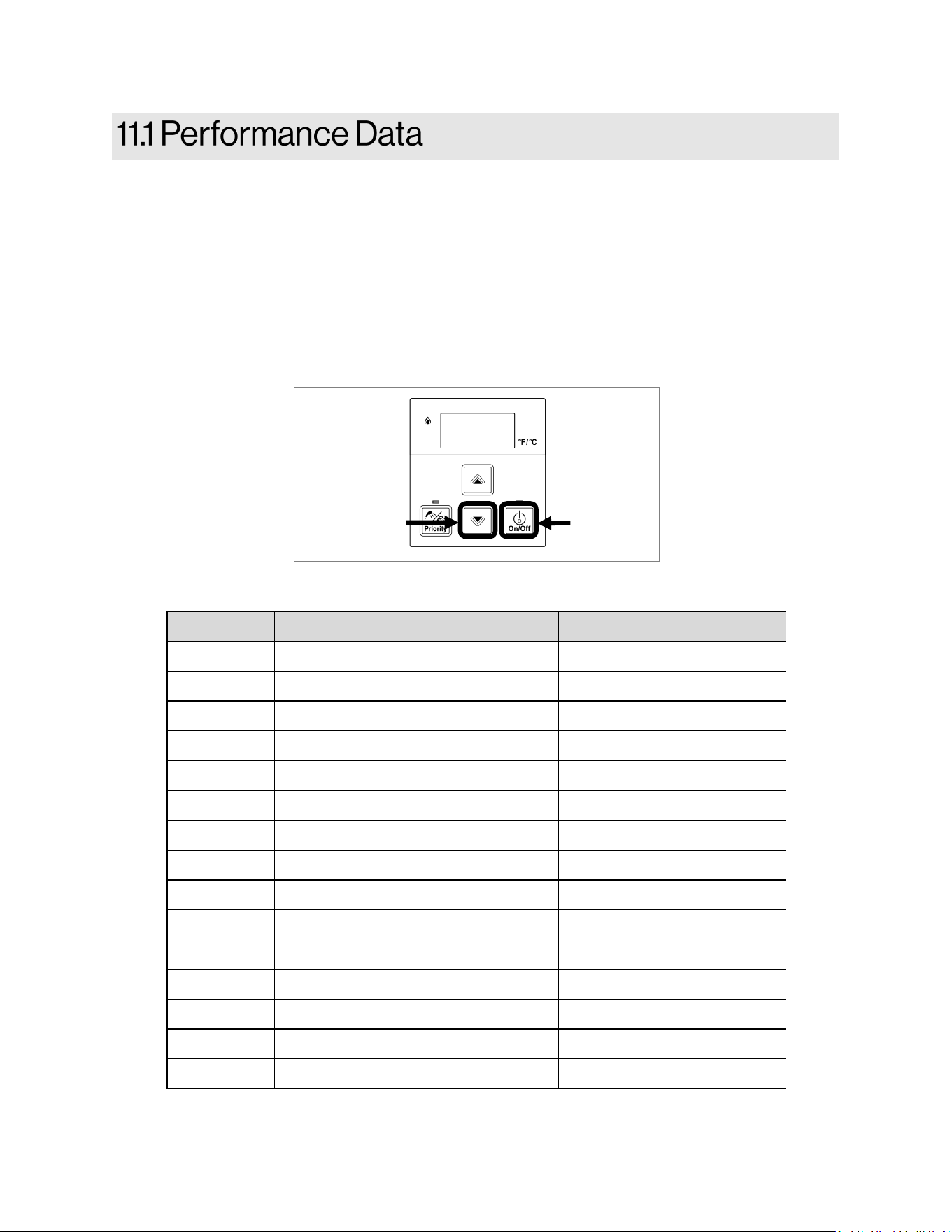
46 Demand Duo™ R-Series (REC) Installation and Operation Manual
To Display Performance Data
1. Press and hold the (Down) button.
2. While holding the (Down) button for 2 seconds, press and hold the “On/Off” button (hold both
buttons simultaneously) (Figure 43)
3. Use the (Up) and (Down) buttons to scroll to the desired information described in Table 11:
Performance Data Table.
4. To exit performance data, repeat step 2 above.
5. When complete, the set temperature appears in the display.
No. Data Unit
01 Water Flow Rate 0.1gal/min
02 Outgoing Temperature °F
03 Combustion Hours x100 Hours
04 Combustion Cycles *
05 Fan Frequency Hz
06 Additional Controllers Connected *
07 Water Flow Control Position 0=Mid, 1=Open, 2=Closed
08 Inlet Thermistor Temperature °F
09 Fan Current 10mA
11 HEX Outlet Temperature °F
12 Bypass Flow Control Position Degrees of opening
19 Pump Hours x100 Hours
20 Pump Cycles *
30 Upper Tank Thermistor Temperature °F
31 Lower Tank Thermistor Temperature °F
Table 11: Performance Data
❷
Figure 43
❶
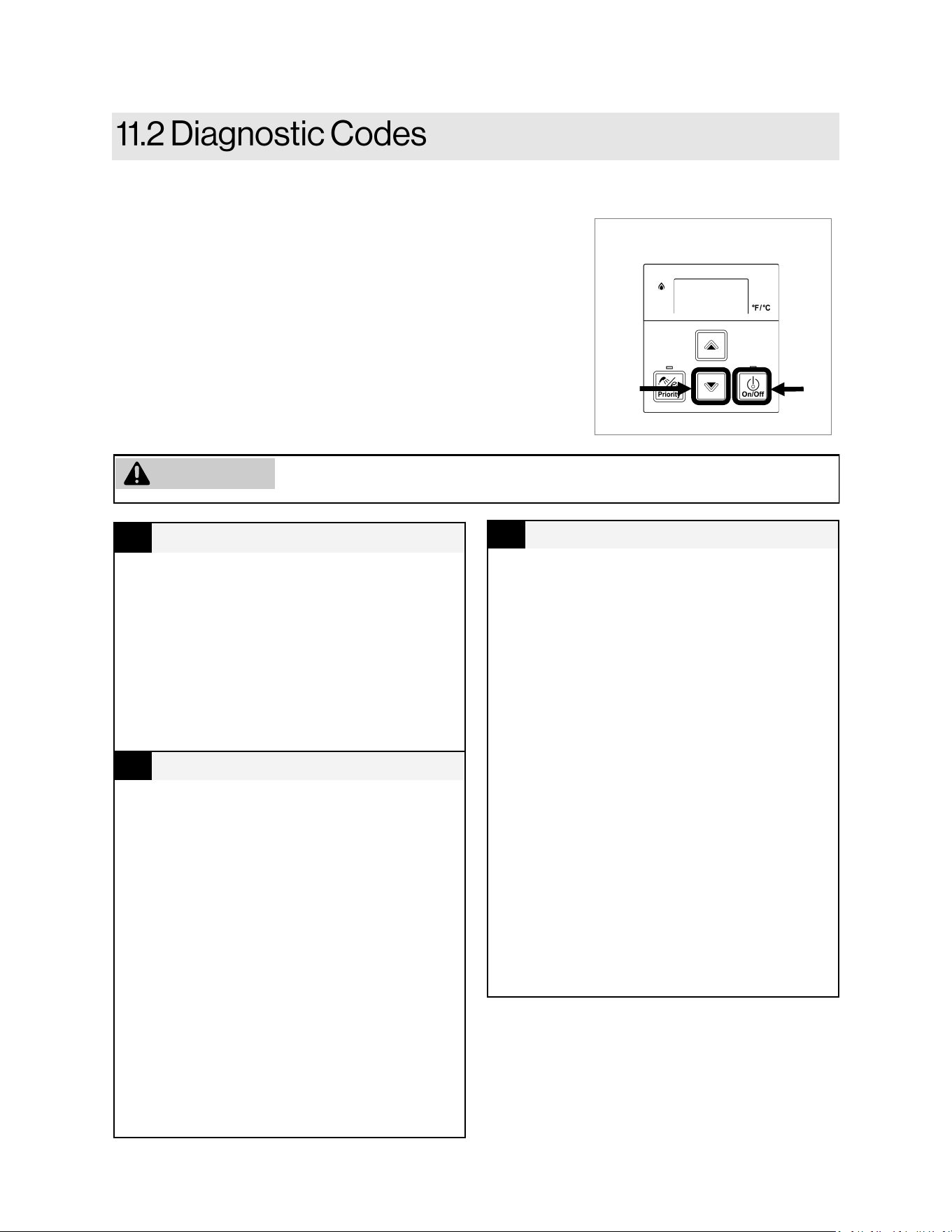
Demand Duo™ R-Series (REC) Installation and Operation Manual 47
To Display Diagnostic Information
1. Turn off the water heater by pressing the “On/Off” button.
2. Press and hold the “On/Off” for 2 seconds and then the
(Up) button simultaneously.
3. The last nine maintenance codes display and flash one after
the other.
4. To exit diagnostic codes and return the water heater to
normal operation, press and hold the “On/Off” button for 2
seconds and then the (Up) button simultaneously.
5. Turn on the water heater by pressing the “On/Off” button.
This water heater is designed to display diagnostic codes. If there is a potential operation concern, refer
to the code and remedy in this section.
❷
Figure 44
❶
10
Air Supply or Exhaust Blockage
• Confirm exhaust vent / flue is not
blocked.
• Confirm Intake Filter Exhaust Connector
(IFEC) is not blocked or dirty.
• Check all vent components for proper
connections.
• Ensure approved venting materials are
being used.
• Check fan for blockage.
• Verify High Altitude setting is set
properly.
11
No Ignition (Heater Not Turning On)
• Check that the gas is turned on at the
water heater, meter, or cylinder.
• If the system is propane, make sure that
gas is in the tank.
• Ensure appliance is properly grounded.
• Ensure gas type and pressure are
correct.
• Ensure gas line, meter, and/or regulator
is sized properly.
• Bleed all air from gas lines.
• Verify dip switches are set properly.
• Ensure igniter is operational.
• Check igniter wiring harness for damage.
• Check gas solenoid valves for open or
short circuits.
• Remove burner cover and ensure all
burners are properly seated.
• Remove burner plate and inspect burner
surface for condensation or debris.
• Check the ground wire for the PC board.
12
No Flame
• Check that the gas is turned on at the
water heater, gas meter, or cylinder.
• Check for obstructions in the flue outlet.
• If the system is propane, make sure that
gas is in the tank.
• Ensure gas line, meter, and/or regulator
are sized properly.
• Ensure gas type and pressure are
correct.
• Bleed all air from gas lines.
• Ensure proper venting material was
installed.
• Check power supply for loose
connections.
• Check power supply for proper voltage
and voltage drops.
• Ensure flame rod wire is connected.
• Check flame rod for carbon build-up.
• Disconnect and reconnect all wiring
harnesses on unit and PC board.
• Check for DC shorts at components.
• Check gas solenoid valves for open or
short circuits.
• Remove burner plate and inspect burner
surface for condensation or debris.
Some of the checks below should be performed by a licensed professional.
Owners should never attempt any action that they are not qualified to perform.
WARNING
48 Demand Duo™ R-Series (REC) Installation and Operation Manual
14
Thermal Fuse
• Check for restrictions in air flow around
unit and vent terminal.
• Check gas type of unit and ensure it
matches gas type being used.
• Check for low water flow in a circulating
system causing short-cycling.
• Check for foreign materials in
combustion chamber and/or exhaust
piping.
• Check heat exchanger for cracks and/or
separations.
• Check heat exchanger surface for hot
spots which indicate blockage due to
scale build-up. Refer to instructions in
manual for flushing heat exchanger.
• Hard water must be treated to prevent
scale build up or damage to the heat
exchanger.
• Measure resistance of safety circuit.
• Ensure high fire and low fire manifold
pressure is correct.
• Check for improper conversion of
product.
16
Over Temperature Warning
(Safety shutdown because unit is too
hot)
• Check for restrictions in air flow around
unit and vent terminal.
• Check for low water flow in a circulating
system causing short-cycling.
• Check for foreign materials in
combustion chamber and/or exhaust
piping.
• Check for blockage in the heat
exchanger.
19
Electrical Grounding
• Check all components for electrical
short.
32
Outgoing Water Temperature Sensor
• Check sensor wiring for damage.
• Measure the resistance of the sensor.
(See Electrical Diagnostics)
• Clean sensor of scale build-up.
• Replace sensor if necessary.
33
Heat Exchanger Outgoing Temperature
Sensor
• Check sensor wiring for damage.
• Measure resistance of sensor.
• Replace sensor.
34
Combustion Air Temperature Sensor
• Check for restrictions in air flow around
unit and vent terminal.
• Check sensor wiring for damage.
• Measure resistance of sensor.
• Clean sensor of scale build-up.
• Ensure fan blade is tight on motor shaft
and is in good condition.
• Replace sensor.
35
Upper Tank Temperature Sensor
• Check sensor wiring for damage.
• Measure resistance of sensor. (See
Electrical Diagnostics)
• Replace sensor if necessary.
36
Lower Tank Temperature Sensor
• Check sensor wiring for damage.
• Measure resistance of sensor. (See
Electrical Diagnostics)
• Replace sensor if necessary.
51
Inlet water temperature thermistor
• Check sensor wiring for damage.
• Measure resistance of sensor.
• Clean sensor of scale build-up.
• Replace sensor.
52
Modulating Solenoid Valve Signal
• Check modulating gas solenoid valve
wiring harness for loose or damaged
terminals.
• Measure resistance of valve coil.
61
Combustion Fan
• Ensure fan will turn freely.
• Check wiring harness to motor for
damaged and/or loose connections.
• Measure resistance of motor winding.
Demand Duo™ R-Series (REC) Installation and Operation Manual 49
Lc
#
Scale Build-up in Heat Exchanger (when
checking maintenance code history,
“00” is substituted for “LC”)
• LC0~LC9 indicates that there is scale
build up in the heat exchanger and that
the heat exchanger needs to be flushed
to prevent damage. Refer to the flushing
instructions in the manual. Hard water
must be treated to prevent scale build
up or damage to the heat exchanger.
To operate the water heater temporarily
until the heat exchanger can be flushed,
push the “On/Off” button five times.
Repeated LC codes will eventually lockout
the water heater.
SS
Service Soon
• Clean inlet water supply filter.
• On new installations ensure hot and cold
water lines are not reversed.
• Verify you have at least the minimum
flow rate required to fire unit.
• Check for cold to hot cross over. Isolate
circulating system if present.
• Turn off cold water to the unit, open
pressure relief valve; if water continues
to flow, there is bleed over in your
plumbing.
• Verify turbine spins freely.
• Measure the resistance of the water flow
control sensor.
• If the display is blank and clicking is
coming from the unit, disconnect the
water flow servo motor (GY, BR, O, W,
P, BL, R). If the display comes on then
replace the water flow servo motor.
ff
Maintenance has been performed
Indicates a licensed professional performed
maintenance or corrected an issue.
No Code - Nothing happens when pump is
activated
• Clean inlet water supply lter.
• Verify you have at least the minimum ow
rate required to re unit.
• Verify turbine spins freely.
• Measure the resistance of the water ow
control sensor.
70
PC Board
• Check the connection harness at the
connection on the PC board. Inspect for
any damage.
• Replace PC board.
71
Solenoid Valve Circuit
Replace the PC Board.
72
Flame Sensing Device
Replace the PC Board.
79
Water Leak Detected
Water has been detected at the bottom of
the unit. Turn off water supply. Check all
plumbing internally for leakage.
63
Recirculation Low Flow
• Ensure the inlet water filter is clean and
free of debris.
• Ensure Parameter setting are correctly
set for recirculation mode.
• Ensure Pump supply voltage.
• Ensure the wiring harness to the pump
and PCB for damaged and/or loose
connections.
• Ensure air is removed from the
recirculation line.
65
Water Flow Control
The water flow control valve has failed to
close during the bath fill function.
Immediately turn off the water and
discontinue the bath fill function. Contact a
licensed professional to service the
appliance.
66
Bypass Flow Servo
• Measure the resistance values and
voltage of the bypass servo valve.*
• Ensure the harness and connector are
not wet.
• If the voltage from the PC Board is
abnormal, replace the PC Board;
otherwise, replace the bypass servo
valve.
50 Demand Duo™ R-Series (REC) Installation and Operation Manual
Limited Warranty for Demand Duo™ R Series - CHS199100REC / CHS19980REC
What is Covered?
The Rinnai Standard Limited Warranty covers any defects in materials or workmanship when the
product is installed and operated according to Rinnai written installation instructions, subject to the terms
within this Limited Warranty document. This Limited Warranty applies only to products that are installed
correctly in the United States. Improper installation may void this Limited Warranty. It is recommended
that a trained and qualified professional who has attended a Rinnai installation training class complete
your installation. This Limited Warranty coverage, as set out in the table below, extends to the original
purchaser and subsequent owners, but only while the product remains at the site of the original
installation, and terminates if the product is moved or reinstalled at a new location.
Item
Period of Coverage (from date of purchase)
Commercial Applications Only
Heat Exchanger 8 years [1]
Storage Tank 6 years [1]
All Other Parts and Components
5 years
Reasonable Labor 1 year
Table 12: Warranty Period of Coverage
[1] For commercial applications, the heat exchanger warranty is 8 years or 12,000 combustion hours,
whichever occurs first.
Notes: From date of purchase, period of coverage is reduced to 8 years or 12,000 combustion hours,
whichever occurs first, if the Rinnai Tankless Water Heater temperature settings exceed 160°F (71°C).
What Will Rinnai Do?
Rinnai will repair or replace the covered product or any part or component that is defective in materials or
workmanship as set forth in the above table. Rinnai will pay reasonable labor charges associated with the
repair or replacement of any such part or component during the term of the labor warranty period. All repair
parts must be genuine Rinnai parts. All repairs or replacements must be performed by a qualified
professional who is properly trained to do the type of repair.
Replacement of the product may only be authorized by Rinnai at its sole discretion. Rinnai does not
authorize any person or company to assume for it any obligation or liability in connection with the
replacement of the product. If Rinnai determines that repair of a product is not possible, Rinnai may replace
the product with a comparable product at Rinnai’s sole discretion. The warranty claim for product parts and
labor may be denied if a component or product returned to Rinnai is found to be free of defects in material
or workmanship; damaged by improper installation, use or operation; or damaged during return shipping.
How To Obtain Service
For the name of a trained and qualified professional, please contact your place of purchase, visit the Rinnai
website (www.rinnai.us), call Rinnai at 1-800-621-9419 or write to Rinnai at 103 International Drive,
Peachtree City, Georgia 30269.
Proof of purchase is required to obtain warranty service. You may show proof of purchase with a dated
sales receipt, or by registering within 30 days of purchasing the product. To register your Rinnai Tankless
Water Heater, please visit www.rinnai.us. For those without internet access, please call
1-800-621-9419. Receipt of registration by Rinnai will constitute proof-of-purchase for this product.
Registration of product installed in new home construction may be verified with a copy of the closing papers
provided by the initial home buyer. However, registration is not necessary in order to validate this Limited
Warranty.

Demand Duo™ R-Series (REC) Installation and Operation Manual 51
• Accident, abuse, or misuse
• Alteration of the product or any component part
• Misapplication of this product
• Improper installation (such as but not limited to)
− Product being installed in a corrosive
environment
− Condensate damage
− Improper venting
− Incorrect gas type
− Incorrect gas or water pressure
− Absence of a drain pan under the
appliance
• Water quality
• Improper maintenance (such as but not limited
to scale build-up, freeze damage, or vent block-
age)
• Incorrect sizing
• Any other cause not due to defects in materials
or workmanship
• Problems or damage due to fires, flooding, elec-
trical surges, freezing or any acts of God.
• Force majeure
There is no warranty coverage on product installed in a closed loop application, commonly associated
with space heating only applications.
This Limited Warranty does not apply to any product whose serial number or manufacture date has
been defaced.
This Limited Warranty does not cover any product used in an application that uses chemically treated
water such as a pool or spa heater.
Limitation on Warranties
No one is authorized to make any other warranties on behalf of Rinnai America Corporation. Except as
expressly provided herein, there are no other warranties, expressed or implied, including, but not limited
to warranties of merchantability or fitness for a particular purpose, which extend beyond the description
of the warranty herein.
Any implied warranties of merchantability and fitness arising under state law are limited in duration to the
period of coverage provided by this Limited Warranty, unless the period provided by state law is less.
Some states do not allow limitations on how long an implied Limited Warranty lasts, so the above limita-
tion may not apply to you.
Rinnai shall not be liable for indirect, incidental, special, consequential or other similar damages that
may arise, including lost profits, damage to person or property, loss of use, inconvenience, or liability
arising from improper installation, service or use. Some states do not allow the exclusion or limitation of
incidental or consequential damages, so the above limitation may not apply to you.
This Limited Warranty gives you specific legal rights, and you may also have other rights which vary
from state to state.
www.rinnai.us/warranty
What Is Not Covered?
This Limited Warranty does not cover any failures or operating difficulties due to the following: