Loading ...
Loading ...
Loading ...

Notes for installer
23
Installation
The machine is transported to the installation site while still in the
packaging. Do not remove the packaging until right before installa-
tion.
The machine may be transported or lifted from the wooden frame
only with the lateral mounting flaps mounted.
First lift the machine at the installation site by the wooden frame. The
suspension points for lifting hooks/straps are located under the side
columns between the screw-on feet.
During installation, remember that the clearance next to and behind
the machine columns must amount to at least 23⅝" (600mm) so that
the side plates remain accessible.
The machine should be set up so that the light shines parallel to the
infeed table as much as possible.
The clearance in front of the machine must amount to at least
60“ (1.5m) to prevent a heating of foreign materials (furniture, walls).
There should be a clearance of at least 39” (1m) above the machine.
For anchoring requirements, local codes must be observed.
During the transport of the machine, pay attention to its stability.
The iron may not be transported without the wooden frame (e.g., in
case of a move). For a new transport, lift the iron onto the wooden
frame and fasten it there.
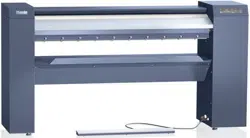
Setting up the rotary iron
Dismantle the mounting flaps on the left and right sides.
Check the roller and front and outside of the side columns using a
level.
Align the machine using the screw-on feet in such a way that the
side columns and roller are level with each other. In the process, the
feet may be unscrewed a maximum of 2 ⅜" (60mm).
Counter the screw-on feet according to the alignment using the
nuts (under the side columns).
Electrical connection
All electrical work must be performed by a qualified service techni-
cian in accordance with all applicable codes and standards.
- The electrical connection and wiring diagram are located behind the
mounting flap of the right side column.
- The values for the electrical connection and fuse rating can be
found on the data plate (see the “Technical data” chapter in this
document).
Loading ...
Loading ...
Loading ...