
>
Product User Manual
Digital Inverter Gas-shielded
Welding Machine
MIG-120/130/160/200//250/
Model: Model code:

Content
s
1 Safety instruction-------------------------------------- P
01
Safety
01
Product User Manual
General Description
Circuit Diagram
2 Characteristics of digital Inverter gas-shielded
welding machine-------------------------------P
02
3 Schematic diagram of main circuit-----------
P
03
02
03
Main Paramete
4 Basic parameters------------------------------------ P
03
04
9 Common Malfunction Analysis and Solutiont
P
11
Troubleshooti
09
5-1 Front panel structure-----------------------------
P
04
5-2 Back panel structure-----------------------------
P
05
5-3
Front panel structure of digital screen-- P
05
Panel Structure
05
06
6-1 Connection of input cable-----------------------
P06
6-2 Installation of MMA welding----------------
P
06
6-3 Installation of gas shielded arc welding---
P
07
6-4 Installation of gas shielded arc welding---
P
08
6-5 Installation of gas shielded arc welding---
P
09
Installation & Operation
7-1 WorkingEnvironment---------------------------P
10
Caution
07
Maintenance
08
8 Maintenance of welding machine--------------P
11
1
01
.........................................................................................................................................................................................
.
Produc User Manual
1
Safety instruction
Safety
As the user's manual of digital MIG series inverter welding machine, this Manual is only
for the MIG series welder. No prior notice will be given in case of any change.
In the benefit of you and others, we recommend you to read and fully understand
this Manual before installation and operation.
Note
Please install and use strictly according to the Manual!
Electrical connection can be done only after the power of the
distribution box is turned off. The operation process shall conform to
relevant safety operation rules.
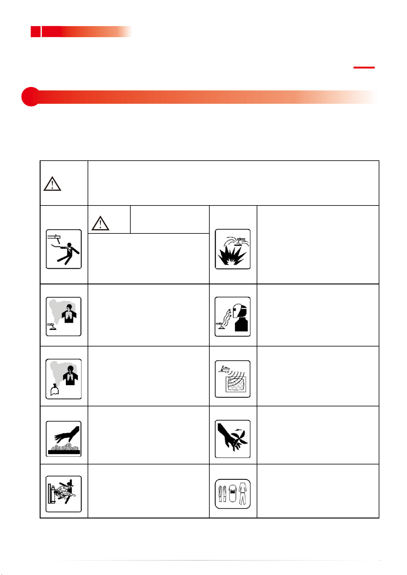
Warning
An electric shock may
hurt or even kill people.
Welding operation may cause
fire or explosion!
Welding spatter may ignite
combustibles nearby.
Combustibles shall be placed at
least 10m from the welding site.
Prevent the spatter from falling
on clothes or body.
Please turn off the power of the
distribution box before wiring.
Do not touch exposed conductive
parts.
The welding fume is harmful to health.
Do not inhale the fume produced
during welding. Clean up the greasy
dirt on work piece. Keep the welding
site in ventilation. Smoke and dust
exhausting facility shall be arranged
at
the welding station.
The arc light may hurt the eyes and
the skin.
Strong arc light may hurt the eyes.
The ultraviolet rays produced by the
electric arc may hurt the skin and the
eyes, and please wear labor protection
clothes properly during welding.
Inert gases are harmful to the human body
Inert gases are harmful to the human body
and even cause suffocation, so please
choose a well-ventilated environment for
welding. If not, please close the gas cylinder
valve.
High-frequency arc ignition may
cause electromagnetic radiation
Radiation may interfere with other
devices! Contact arc ignition can be
used to avoid interference.
The overheated part may burn the skin, and
do not touch the overheated welding
part.
The overheated part may burn the skin, and do
not touch the overheated welding part.
High-speed moving objects may
cause hurt.
and do not put your hands or a thin
objects into the fan hood.
Please cover the open shell during
welding.
The gas cylinder may explode.
so do not to heat it.
It is preferred to keep the gas cylinder
away from the welding site and fix it
well.
Personal protection.
To prevent eye and skin injury, please
comply with the rules of labor safety
and health and wear necessary
protective clothing!

2
2 Characteristics of digital Inverter gas-shielded welding machine
02
Product User Manual
GENERAL DESCRIPTION
Thank you for buying the digital inverter welding machine . Please
read the Manual carefully before use.
The performance features are as follows:
Use full-digital control system to realize precise control and stable arc
length during welding. Use full-digital wire feeding control system to
realize precise and stable wire feeding.
Friendly operation interface, unified regulating mode, easy to master.
Gas shielded arc welding, MMA welding and Self Shielded arc welding
are available.
IGBT technology and unique control enhance the reliability of the
welding machine.
High duty cycle, long time welding is available.
Closed loop feedback control, constant voltage output, workable under
network voltage fluctuation within ±15%.
Adjustable welding voltage and circuit, excellent welding characteristics.
Unique dynamic characteristic control circuit is used in gas shielded arc
welding, stable arc, little splash, good shaping, efficient welding.
Melting ball removing, high no-load and slow wire feeding function
increase the success rate of arc starting.
Stable current and excellent arc starting in MMA welding, and various
welding rods can be used.
Inverter frequency is 35 KHz, greatly reducing the volume and weight of
the welder.
Great reduction in metal loss obviously enhances the welding efficiency
and energy saving effect.
Switching frequency is beyond audiorange, which almost eliminates
noise pollution.
3
03
.........................................................................................................................................................................................
.
Produc User Manual
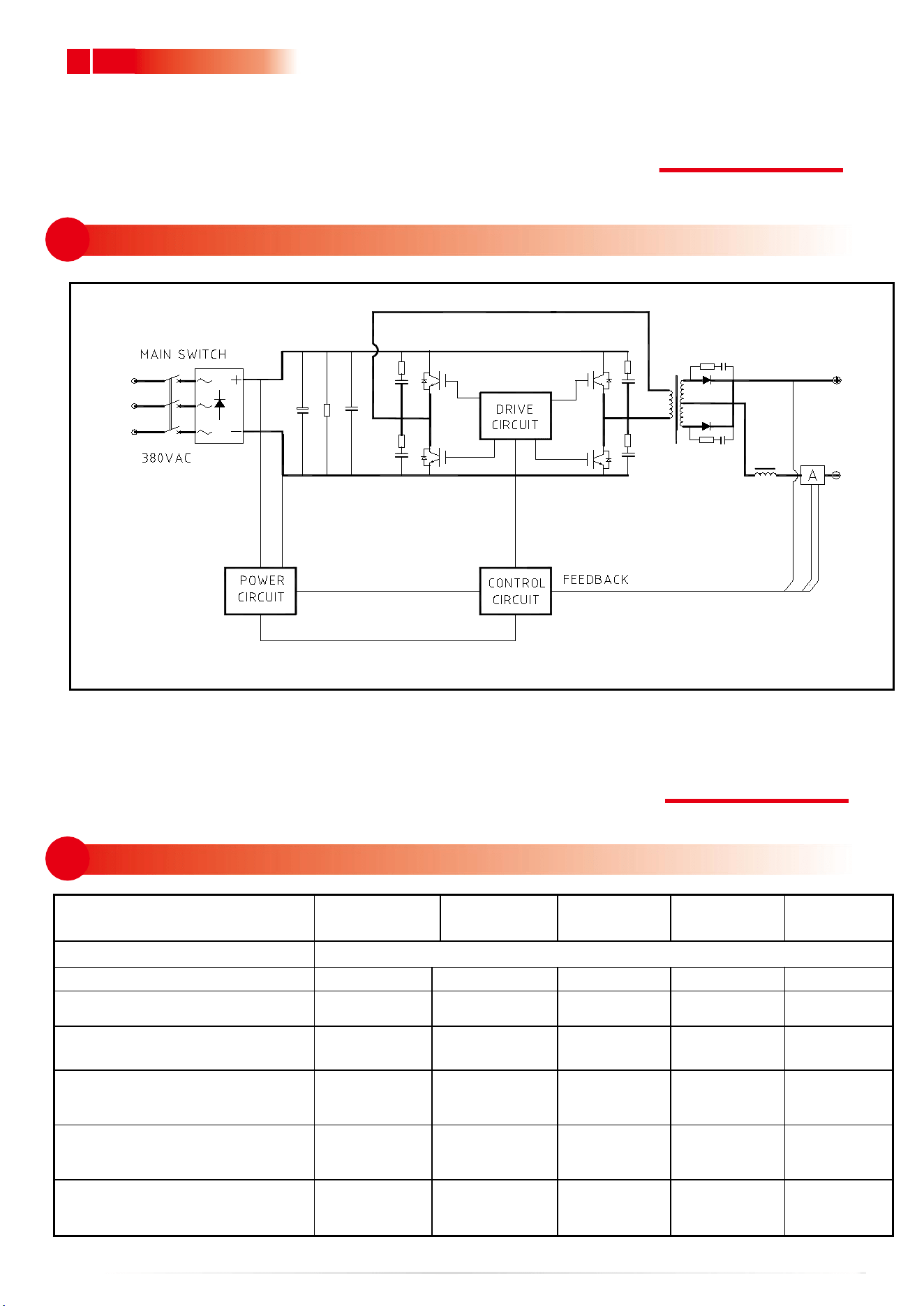
3 Schematic diagram of main circuit
04
4 Basic parameters
CIRCUIT DIAGRAM
MAIN PARAMETER
TYPE
MIG120
MIG130
MIG160
MIG200
MIG250
Input power voltage(V)
Single-phase AC220V±15%,50/60Hz
Rated input current (A)
22
25
32
37
55
Rated power capacity(KVA)
5.1
5.8
7.4
8.6
12.6
Recommended fuse
capacity(A)
40
50
50
60
70
Current adjustment range (A)
(MMA welding)
10~120
10~130
10~
160
10~200
10~250
Current adjustment range (A)
(Gas shielded arc welding)
25~120
25~130
25~
175
25~200
25~250
Voltage adjustment range (V)
(Gas shielded arc welding)
11
~
22
11
~
24
11
~
26
11
~
27
11
~
29
4
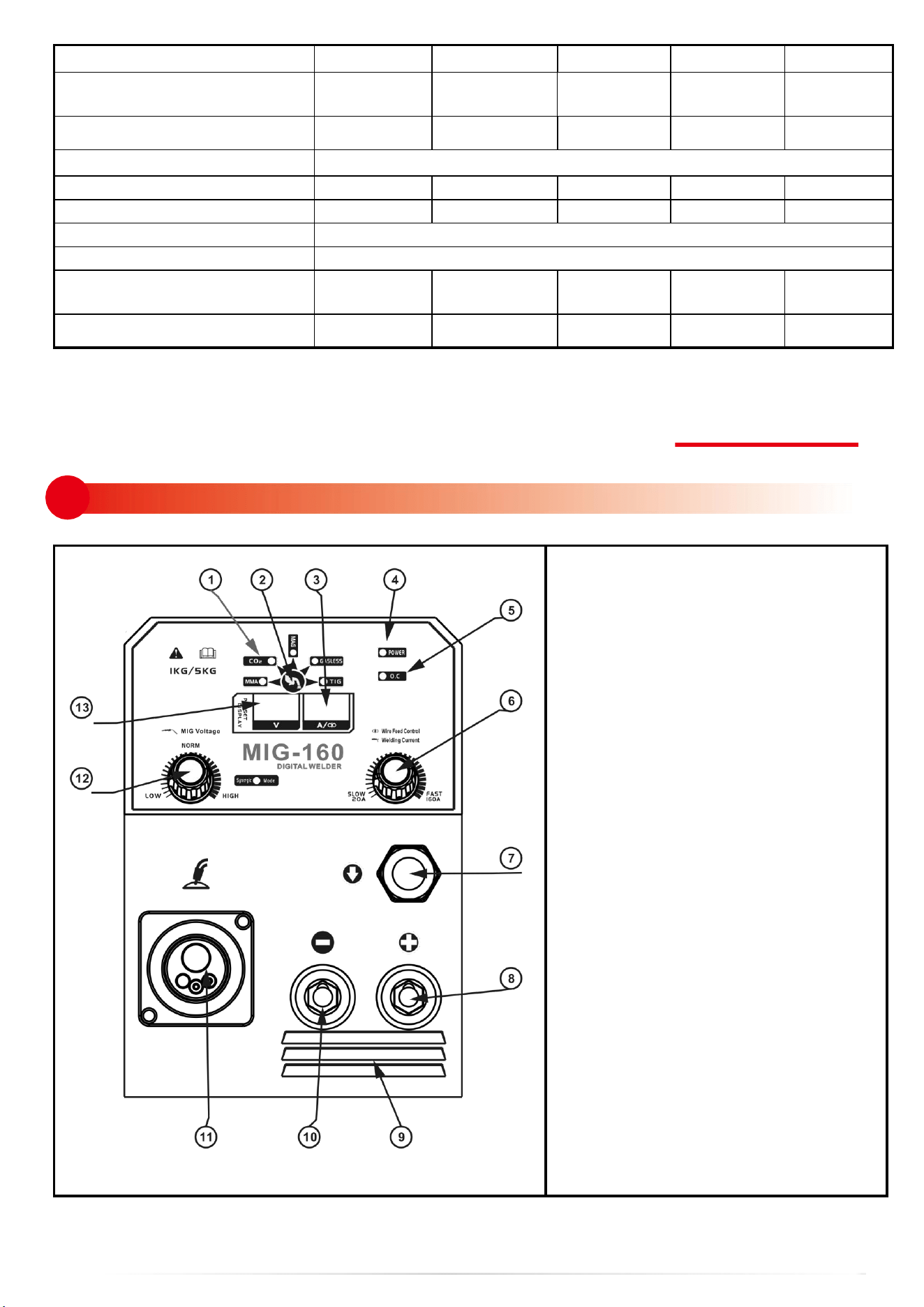
5.1 Front panel structure
05
MAIN PARAMETER
1. Working status display
2. Function switch button
3. Current/Feeding speed display
4. Power LED
5. Overheating LED
6. Current/Feeding speed adjustment
knob
7. Gas/gasless shielded ARC
Crossover sub
8. “+” output terminal
9. Shutters
10. “-” output terminal
11. Euro welding torch connector (in
gas shielded arc welding)
12. Voltage adjustment knob (in gas
shielded arc welding)
13. Voltage display
No-load voltage (V)
50
50
50
52
54
Feeding speed adjustment
range (m/min)
1.5
~
16
1.5
~
16
1.5
~
16
1.5
~
16
1.5
~
16
Welding wire diameter (mm)
0.6/0.8
0.6/0.8
0.6/0.8/1.0
0.6/0.8 /1.0
0.6/0.8/1.0
Rated duty cycle
35% 40
℃
Efficiency (%)
85
85
85
85
85
Power factor
0.7
0.7
0.7
0.7
0.7
Protection class
IP21S
Insulation class
F
Size (mm)
405×210×3
30
405×210×33
495×282×3
65
495×282×3
65
495×282×
365
Weight (Kg)
17
18
18
24
25
5
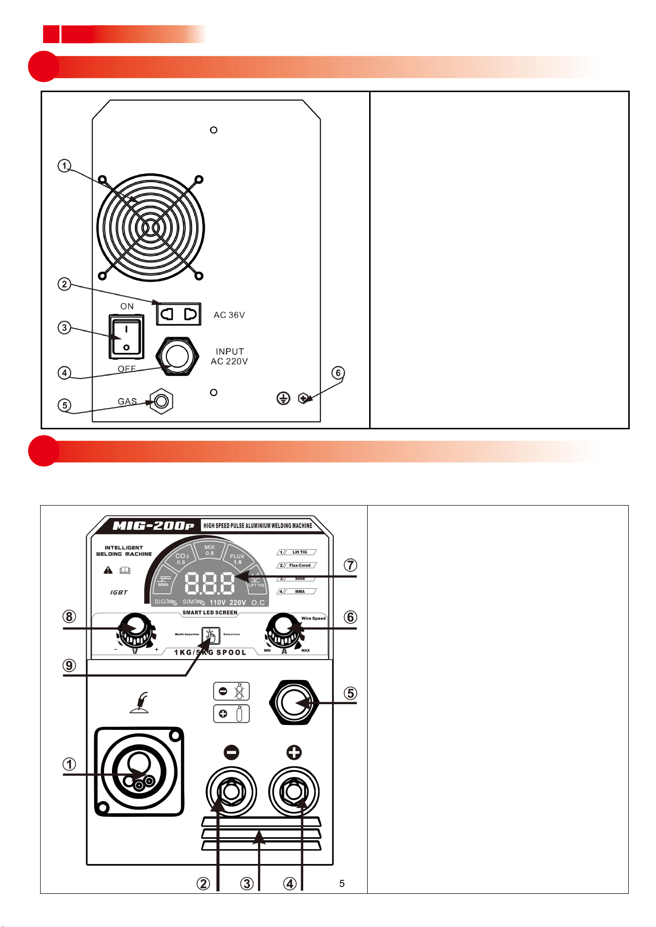
5.2 Back panel structure
.........................................................................................................................................................................................
.
Produc User Manual
1. Fan
2. Pressure reducing valve power supply
(ac-36v)
3. Power switch
4. Input power cable
5. GAS IN
6. Grounding screw
1. Euro welding torch connector
2. Negative output terminal
3. Shutters
4. Positive output terminal
5. Gas/gasless shielded ARC Crossover
sub
6. Current/Feeding speed adjustment
knob
7. LED digital display
8. Voltage adjustment knob
9. Function switch button
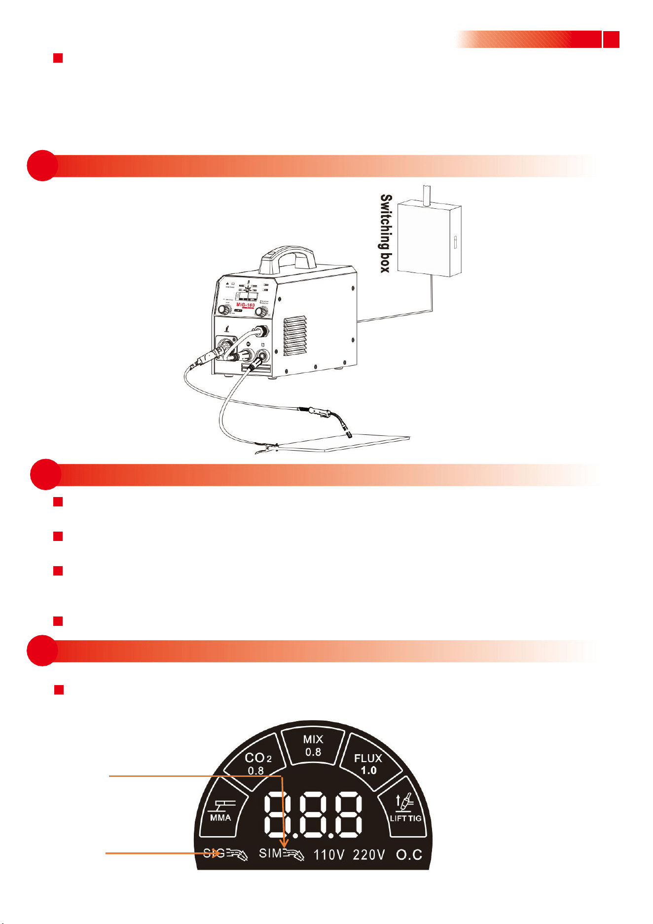
5.3 Front panel structure of digital screen

6
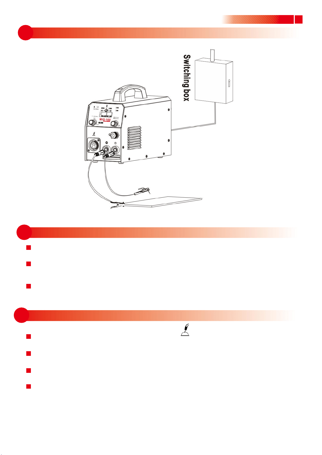
6.2.1 Installation of MMA welding
6.1 Connection of input cable
06
INSTLLATION & OPERATION
Note: ·Please install the machine strictly according to the following steps.
·Electric connection operation should be after turning off the power supply switch of the switch box.
·The protection class of this machine is IP21S, so avoid using it in rain.
(1) A primary power supply cable is available for this welding machine. Connect the power
supply Cable with required voltage. (Note: Earth the machine reliably during connection.)
(2) The primary wire should be connected to the corresponding socket to avoid oxidization.
(3) Use multi-meter to see whether the voltage value varies within the given range.
l
(1) Two air sockets are available for this welding equipment. Connect the plug to the socket
on the panel board. It is possibly damaging to both the plug and socket, if the plug and
the socket are incorrectlyconnected.
(2) The electrode holder cable should be connected to the negative terminal, while the
work piece should be connected to the positive terminal.
(3) Serious attention should be paid to the electrode of the wire. Generally, two modes of
connection of DC welding equipment are available:
● Positive connection:electrode holder to “-”,while work piece to “+”;
● Negative connection:work piece to “-”, while electrode holder to “+”.
Opt the mode according to practical requirements, and incorrect connection may cause
unstable arc, splash and conglutination of rod and work piece etc.
(4) In case that minimum distance between work piece and this welding equipment is over
50m, as a consequence it spells the over-length of the secondary cable including electrode
holder cable and earth cable. Therefore it is necessary to increase the diameter of cable
In order to maintain and improve the performance of voltage output.
.........................................................................................................................................................................................
.
Produc User Manual
7
6.2.2 Installation sketch map
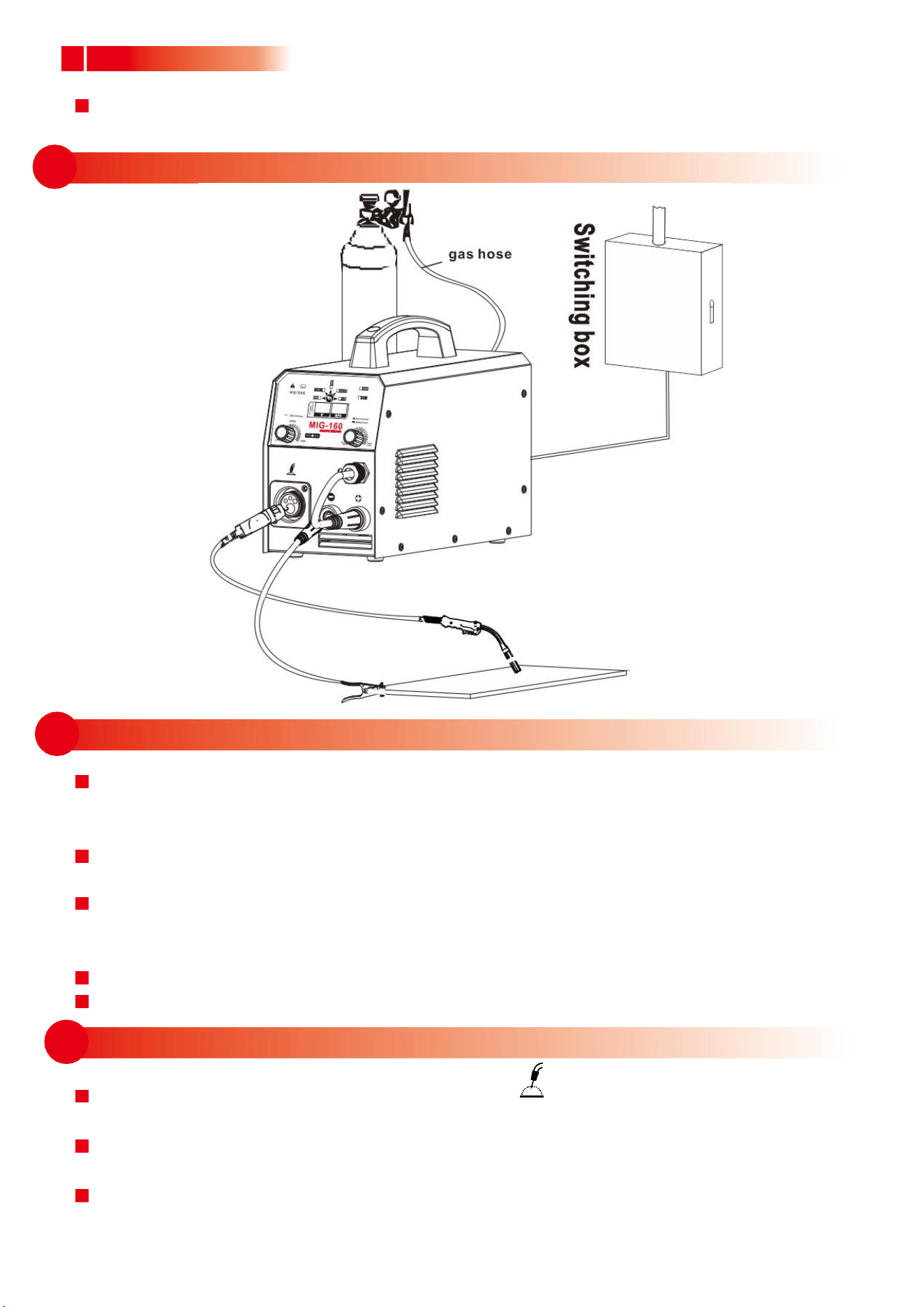
6.3.1 Installation of gas shielded arc welding
6.2.3 Operation
Product User Manua
(1) Turn the power switch on the back panel to “ON” position after the installation according
to the above steps, the machine is started, the power LED turns on, and the fan works.
(2) Turn the conversion switch on the front panel to “MMA” position, and adjust the welding
current adjustment knob according to the workpiece thickness to get the desired welding
performance.
(3) Generally, the required welding current is listed as follows:
Ф2.5: 70-100A; Ф3.2: 110-160A; Ф4.0: 170-220A; Ф5.0: 230-280A
(1) Plug the welding torch into the output socket “ ” on the front panel, and tighten it.
Thread the wire into the torch manually.
(2) Insert the earth cable plug into the negative socket on the front panel, and tighten it
clockwise.
(3) Insert the adapter plug into the positive socket on the front panel, and tighten it
clockwise.
(4) Fix the welding wire coil to the rack axis on the wire feeder; make sure the hole of the
wire feeding wheel matches well with the bolt on the rack axis and the welding wire
diameter. Unfasten the screw on the wire-pressing wheel, and make the wire into the
glove of the wire feed wheel, press the wire tightly, but not too tight, and then thread
the wire into the torch. Press the torch switch to send out the wire Welding gun.
8
6.4.1 Installation of self shielded arc welding
6.3.3 Operation
6.3.2 Installation sketch map
.........................................................................................................................................................................................
.
Produc User Manual
(5) Tightly connect the gas hose, which come from the back of the machine to the copper
nozzle of gas bottle.
(1) After installation according to the above steps, turn the power switch on the back panel
to “ON” position, then the power LED turns on, and the fan works. Open the gas cylinder
valve, and adjust the flow meter to the desired position.
(2) Press the function conversion button on the front panel to convert the function to "CO2 "
or" MAG"
(3) adjust the welding voltage adjustment knob and wire feeding speed adjustment
knob according to practical needs to get the desired welding voltage and welding
current.
(4) Press the welding torch switch, and welding can be carried out.
(5) Cut off the gas 1s after the arc is stopped.
(1) Plug the welding torch into the output socket “ ” on the front panel, and tighten it.
Thread the wire into the torch manually.
(2) Insert the earth cable plug into the positive socket on the front panel, and tighten it
clockwise.
(3) Insert the adapter plug into the negative socket on the front panel, and tighten it
clockwise.
9
6.4.3 Operation
6.4.2 Installation sketch map
6.5 Single pulse gas welding
Product User Manual
(4) Fix the welding wire coil to the rack axis on the wire feeder; make sure the hole of the
wire feeding wheel matches well with the bolt on the rack axis and the welding wire
diameter. Unfasten the screw on the wire-pressing wheel, and make the wire into the
glove of the wire feed wheel, press the wire tightly, but not too tight, and then thread
the wire into the torch. Press the” wire feeding” button to feed the wire out of the
welding gun.
(1) After installation according to the above steps, turn the power switch on the back panel
to “ON” position, then the power LED turns on, and the fan works.
(2) Press the function conversion button on the front panel to convert the function to
"GASLESS ",
(3) Adjust the welding voltage adjustment knob and wire feeding speed adjustment
knob according to practical needs to get the desired welding voltage and welding
current..
(4) Press the welding torch switch, and welding can be carried out.
Switch the welder to aluminum-magnesium welding and aluminum-silicon welding as
shown in the figure below by using the function switch button.(Part of the aircraft)
Aluminum-magnesium
welding
Aluminum-silicon
welding

10
7.2 Good Ventilation
7.5 Overheating Protection
7.1 Working Environment
.........................................................................................................................................................................................
.
Produc User Manual
07
7.4 No Overload
7.3 No Overvoltage
CAUTION
⑴
Welding should be carried out in a relatively dry environment with its humidity of 90%
or less.
⑵
The temperature of the working environment should be within -10C to 40C.
⑶
Avoid welding in the open air unless sheltered from sunlight and rain, and never let
rain or water Infilter the machine.
⑷
Avoid welding in dusty area or environment with corrosive chemical gas.
⑸
Avoid gas shielded arc welding in environment with strong airflow.
This welding machine has so big welding current when working that nature ventilation can
not meet the cooling demand, while the inner fan enables the machine to work steadily by its
effective cooling. Operator should make sure the louvers are uncovered and unblocked. The
minimum distance between the machine and nearby objects should be 30cm. Good ventilation
is of critical importance to the normal performance and service life of the machine.
If the voltage exceeds the permitted limit, the machine will be damaged, so pay attention to
the changes in voltage. Once overvoltage occurs, stop welding and switch off the power.
Remember to observe the max load current at any moment (refer to the optioned duty
cycle). Make sure that the welding current should not exceed the max load current. Over-load
current could obviously shorten the welding equipment’s life, or even burn the equipment.
Overheating protection appears while the machine is of overload status because of
continuous welding for a long time, and a sudden halt of welding occurs. In this case, it is
unnecessary to restart the machine,but just wait for the overheating LED to go out, and
welding can be recovered.
11
08
09
Product User Manual
MAINTENANCE
WARNING: The following operation requires sufficient professional
knowledge on electric aspect and comprehensive security
knowledge. Operators should be holders of valid
qualification certificates which can prove their skills and
knowledge. Make sure the input cable of the machine is
cut off from the electricity before uncovering the welding
machine.
1. Check periodically whether inner circuit connection is ok (esp. plugs). Tighten the loose
connection. If there is oxidization, remove it with sandpaper and then reconnect.
2. Keep hands, hair and tools away from the moving parts such as the fan to avoid personal
injury or machine damage.
3. Clean the dust periodically with dry and clean compressed air. If welding in environment
with heavy smoke and pollution, the machine should be cleaned daily. The pressure of
compressed air should be at a proper lever lest the small parts inside the machine be
damaged.
4. Avoid rain, water and vapor infilter the machine. If there is, dry it and check the insulation
with a megger (including that between the connections and that between the connection
andthe case). Only when there is no abnormal phenomena can welding be continued.
5. Check periodically whether the insulation skin of all cables are perfect. If there is any
dilapidation, wrap it or replace it.
6. Check periodically whether the gas hose has any cracks. If any, get them replaced.
7. Put the machine into the original packing in dry location if it is not to be used for a long time.
TROUBLESHOOTING
WARNING: The following operation requires sufficient professional
knowledge on electric aspect and comprehensive security
knowledge. Operators should be holders of valid qualification
certificates which can prove their skills and knowledge. Make
sure the input cable of the machine is cut off from the electricity
before uncovering the welding machine.

12
9 Common Malfunction Analysis and Solution
.........................................................................................................................................................................................
.
Produc User Manual
Phenomena
Solution
1. The overheating LED
flashes.
1. Check the working current and the working time, and use the machine
according to the parameters in this manual.
2. Check the running situation of the fan. If the fan doesn’t work, check if
there is power supply 220V: If the power supply is ok, check the fan; if
the power supply is abnormal, check the power cable.
3. Replace the thermal switch if it is damaged.
2. The power LED is
off, and there is no
current output.
1. Check if the fan works. If not, the power cable is not in good connection.
2. If the fan works,control PCB board inside the machine fails.
3. No response when
pressing welding
torch switch; the
protection LED is off.
1. Check if the welding torch switch is in good connection.
2. Check the connection condition of the welding torch and the Euro
socket and check the control jack of the Euro socket.
3. Control PCB board inside the machine fails.
4. Press the welding
torch switch to input
gas, but no current
output, and the
protection LED is
off.
1. Check if the power cable connecting the workpiece is in good
connection.
2. Check if the position where the fast socket inserting the fast plug is
correct.
3. Check if the wire feeder is in good connection.
4. Check if the welding torch is damaged.
5. Control PCB board inside the machine fails.
5. Press the welding
torch switch to input
gas, there is current
output, but the wire
feeder doesn’t work.
1. Check if the wire feeder is blocked or damaged.
2. Check if the contact tip of the welding torch is damaged or blocked.
3. Control PCB board inside the machine fails.
6. Press the welding
torch switch, welding
can be carried out,
but the voltage can
not be adjusted.
1. Check if the voltage feedback cable inside the machine is ok.
2. Control PCB board inside the machine fails.
7. Welding current is
unstable.
1. Check the pressure of the wire feeder pole is appropriate.
2. Check if the wire feed wheel matches the welding wire.
3. Check if the contact tip is badly abraded. If it is, replace it and tighten it.
4. Check the quality of the welding wire.
5. Check if the welding torch cable is too winding.
6. Check if the metal connection part of the fast plug is loose.

13
8. The weld bead is not
well protected.
1. Do not remove the welding torch as soon as the welding stops. Thus the
shielded gas can protect the hot weld bead.
2. Prolong the post-flow time, or contact our company.
This machine is in continuous improvement, so other parts may be different except the function
and operation. Your understanding would be greatly appreciated.