INVERTER GMAW (CO
2
) /MAG
WELDING MACHINE
Operation Manual
Thank you for choosing our inverter series welding machine.
Please read and understand this instruction manual carefully
before the installation and operation of this equipment. Thanks
for your cooperation.

1
Catalogue
Usage and Features……………………………………………………2
Safety measures…………………………………………………………2
Installation ……………………………………………………………4
Principle ………………………………………………………………7
Operation ………………………………………………………………8
Technical Data …………………………………………………………10
Maintenance …………………………………………………………11
Electric circuit diagram ………………………………………………13
2
Usage and features
MIG/NB/NBC— series inverter GMAW (CO
2
)/MAG welding machine is a kind of
high-performance universal semiautomatic equipment, it can use diameter of φ0.8
~
φ1.6mm solid wire and flux-cored wire to weld mild steel and low alloy steel structures.
Voltage compensation circuit and auto arc length compensation function thanks to
inverter technology to make sure the stable welding
Low spatter and high deposition rate
Excellent welding joint and stable arc
With easy pulse ignition
Eliminating droplet functionality after welding
Reduce the welder’s labor intensity, especially for long-time welding thanks to
self-lock function
Highly stable welding speed, light, small and easy to be moved
Energy saving and less requirement about circuit capability
Safety measure
Safety measures:
Please operate as to this manual to avoid some accident.
Input power design, the choice of installation area and high pressure gas must
follow the related standards.
Unrelated people are forbidden to close the welding area.
Only qualified people are allowed to install, inspect, maintain and use the
welding machine.
Don’t use the welding machine for other usages (Such as charging, heating and
unfreezing of pipelines)
If the earth is uneven, please avoid the machine topping over.
Avoid the electric shock and burn
Don’t touch live parts.
Only qualified person are allowed to use special diameter copper cable to
connect machine with earth.
Use special copper cable to connect the cable; and the insulated sleeve can not
be broken
Ensure good insulation between people and base metal, when welding in wet
and limited conditions.
Please use safe power grid for aloft work.
Please turn off the power when not using.
3
Guarding against soot and welding gas produced
Please be sure good ventilation to avoid the gas poisoning and suffocating,
especially for the bottom operation.
Lift arc and spatter are harmful
Please wear guarding glass for avoiding arc light, spatter and slag.
Please use protection utensils such as work clothes with long sleeves 、 fur
gloves、leather shoe、apron and so on to keep arc light, spatters and slag away.
Avoid fire, explosion and break accident
● Remove the combustible article to keep spatter away from them. If they can’t be
removed, please cover them with articles which aren’t combustible.
● Cable and base metal should be firmly tightened for avoiding fire.
It is forbidden to welding when welding in combustible gas or welding
container which with combustible materials to avoid the explosion.
Welding hermetic container would cause breaking dangers.
Prepare the fire extinguisher in advance.
Avoid whirligig parts hurt people
Figures, fair and clothes shouldn’t close to whirling parts such as cooling fun and wire feed
roll.
When wire is feeding, please don’t put welding gun close to eyes, face and other parts of
body to provide against hurting.
Avoid the air bottle toppling over and the regulator is
broken.
Air bottle toppling maybe causes a major personal injury
Air bottle wit h high pressure maybe causes a major personal injury
Unsuitable flow meter for air bottle maybe causes a major personal injury!
Please check whether the gas in the air bottle meet the technological
requirement and ensure all the flow meter and pipe connection are in good
status.
Avoid hurt other people when moving the machine.

4
Please make sure there is nobody under the machine or on the front when
moving the welding machine by folk lift.
When lift the machine, please make sure the cable is tightened to avoid
personal injury!
Installation
1. Environment
It should put in the room with no direct shinning, no rain, low humidity and less
dusty, the temperature should between 10℃ and 40℃.
Gradient should not be less then 15°.
Wind is not allowed while welding, get a shield if necessary.
Welding machine should keep distance with wall more than 20cm and with other
welding machine more than 10cm.
Provide against freezer while using water-cooling welding gun.
2. Power quality
Wave form should be standard sine wave, virtual value is 220 V±15% or 380V±15%,
frequency is 50Hz-60Hz
3-phase voltage unbalance ≤5%
3.Input power
model
MIG-250Y
NB-250
MIG-270Y
NB-270
MIG-315Y
NB-315
Input power source
Single-phase
AC220V
3-phase AC380V
3-phase AC380V
Power
source
capability
Small
capability
Power
grid
12KVA
20KVA
22KVA
Motor
20KVA
25KVA
30KVA
Input
protection
fuse
20KVA
25A
30A
Circuit
breaker
20A
30A
32A
Cable
Input
side
≥1.5mm²
≥2.5mm²
≥2.5mm²
Output
side
25mm²
35mm²
35mm²
Earth
cable
≥1.5mm²
≥2.5mm²
≥2.5mm²
Notice: The above capacity of the fuse and circuit breaker is just for reference.
5
4. Equipment installation
This machine is small, light and easy to be moved by the welder, if there is any
wheelbarrow will be more convenient but please ensure the grand is smoothxz
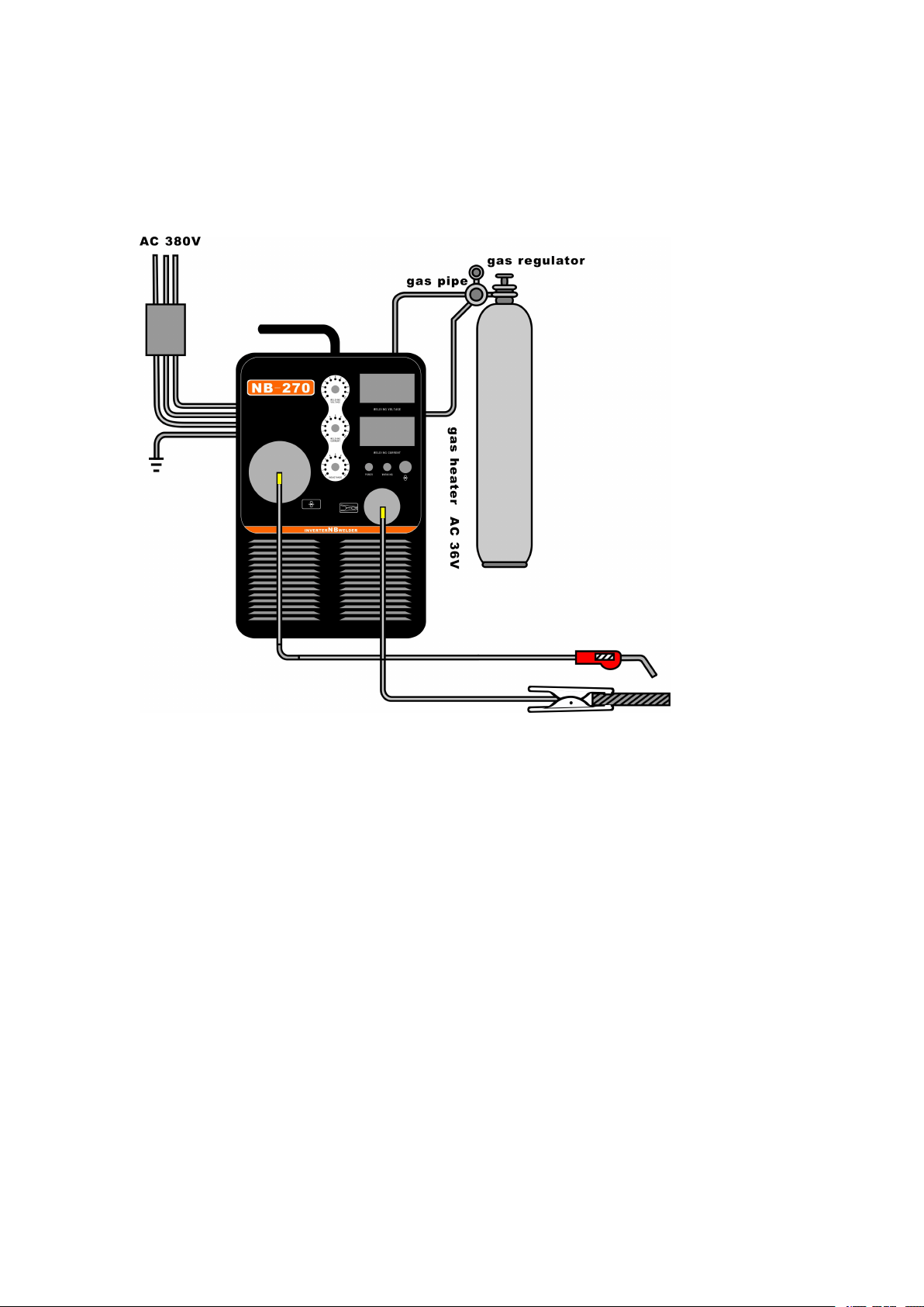
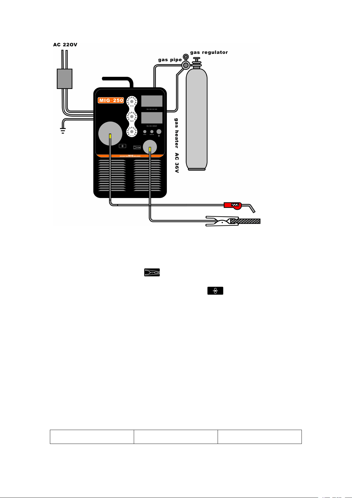
MIG/NB/NBC— series welding machine outside gas connection as figure 1 and figure 2
Figure 1: Connection diagram
6
Figure 2: Connection diagram
Operation:
1) Connect connecting terminal with base metal by cable
2) Electrode holder joins to be connected with terminal .
3) Connect the gas pipe with wire feeder to CO2 flow meter.
4) Cable of gas regulator heater connect to the output socket on the back of welding
machine
5) Connect the 3-phase cable on switch panel and earth cable should be well grounded
6) Turn on the automatic air switch on the back of welding machine.
5. Usage:
Turn on the automatic air switch on the switch panel, welding indicator lights up and
cooling fan runs. Push the wire feeding button down, wire is fast feeding. You can preset
parameter through buttons on panel. When push down the welding gun switch, wire
feeder start feeding and CO
2
gas comes out from torch head then the welding can start.
Customer can refer to list2. After welding, close CO
2
gas and turn off the power.
Welding current(A)
Welding voltage(V)
Wire diameter(mm)
7
60~80
17~18
Ф1.0
80~130
18~21
Ф1.0、Ф1.2
130~200
20~24
Ф1.0、Ф1.2
200~250
24~27
Ф1.0、Ф1.2
250~350
26~32
Ф1.2、Ф1.6
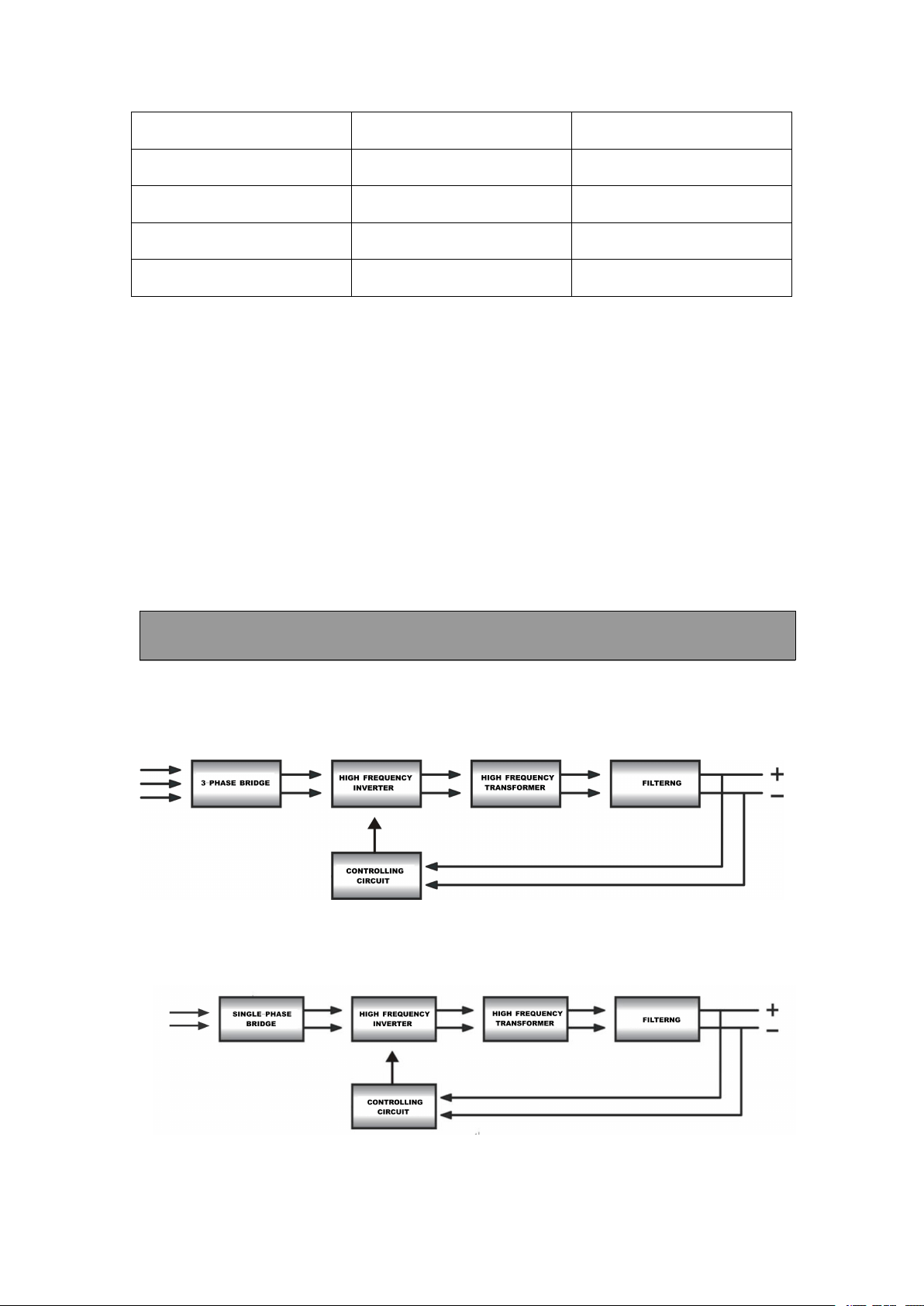
Brief principle
MIG/NB/NBC- series welding machine principle diagram is shown as figure3 and figure
4.
3~380V50HZ
Figure 3: Schematic
1~220V50HZ
Figure 4: Schematic
8
This machine adopt IGBT inverter soft switch technology, input power is single-phase
220V or 3-phase 380V, raise the frequency, reduce the voltage, rectification and filtering,
then get the direct current suitable for welding. The whole process raise the dynamic
response speed and reduce the size and weight of welding machine. Circuit is closed-loop
control, excellent grid compensation for welding.
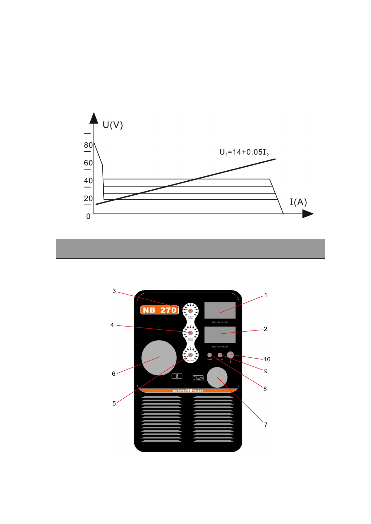
MIG/NB/NBC— series inverter welding machine output characteristic is shown as figure 5:
Figure 5: Output characteristic
Operation
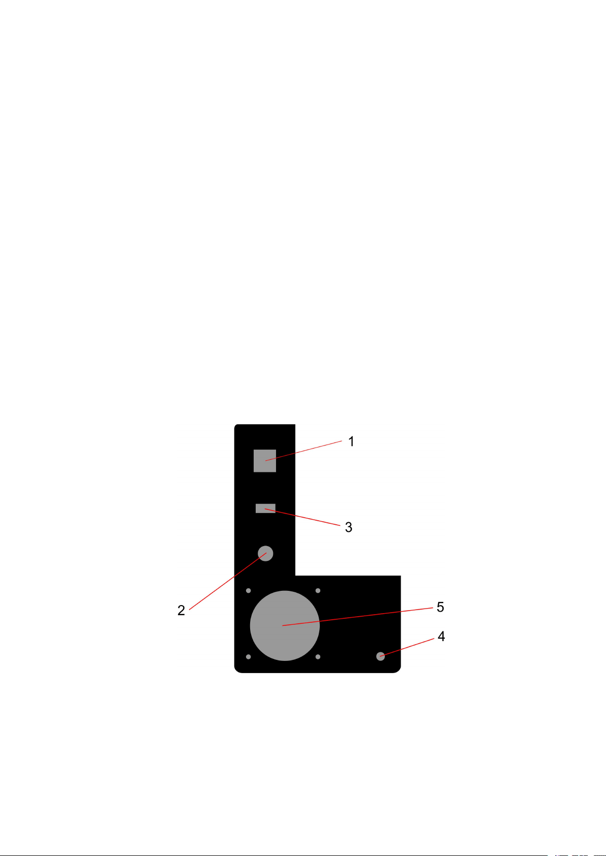
1. Front panel
Front panel takes NB-270 for example, is shown as figure 6. Other models are similar.
Figure 6: Front panel diagram
9
1. Output current meter
It shows relative value about wire feeding speed when no-load welding and shows
actual current value when welding
2. Output voltage meter
It shows preset value when no-load welding and actual value when welding.
3. Voltage adjusting knob
Adjust welding voltage.
4. Current adjusting knob
Adjust the welding current.
5. Inductance adjusting knob
It can turn the welding stability level and spatter.
6. Welding gun cable socket
7. Electrode holder cable socket
8. Working indicator
It shows if the welding machine is power on.
9. Protection indicator
It shows if the temperature inside the machine is too high. The machine will stop
working when it light up.
10. Manual wire feeding knob, using for fast feeding.
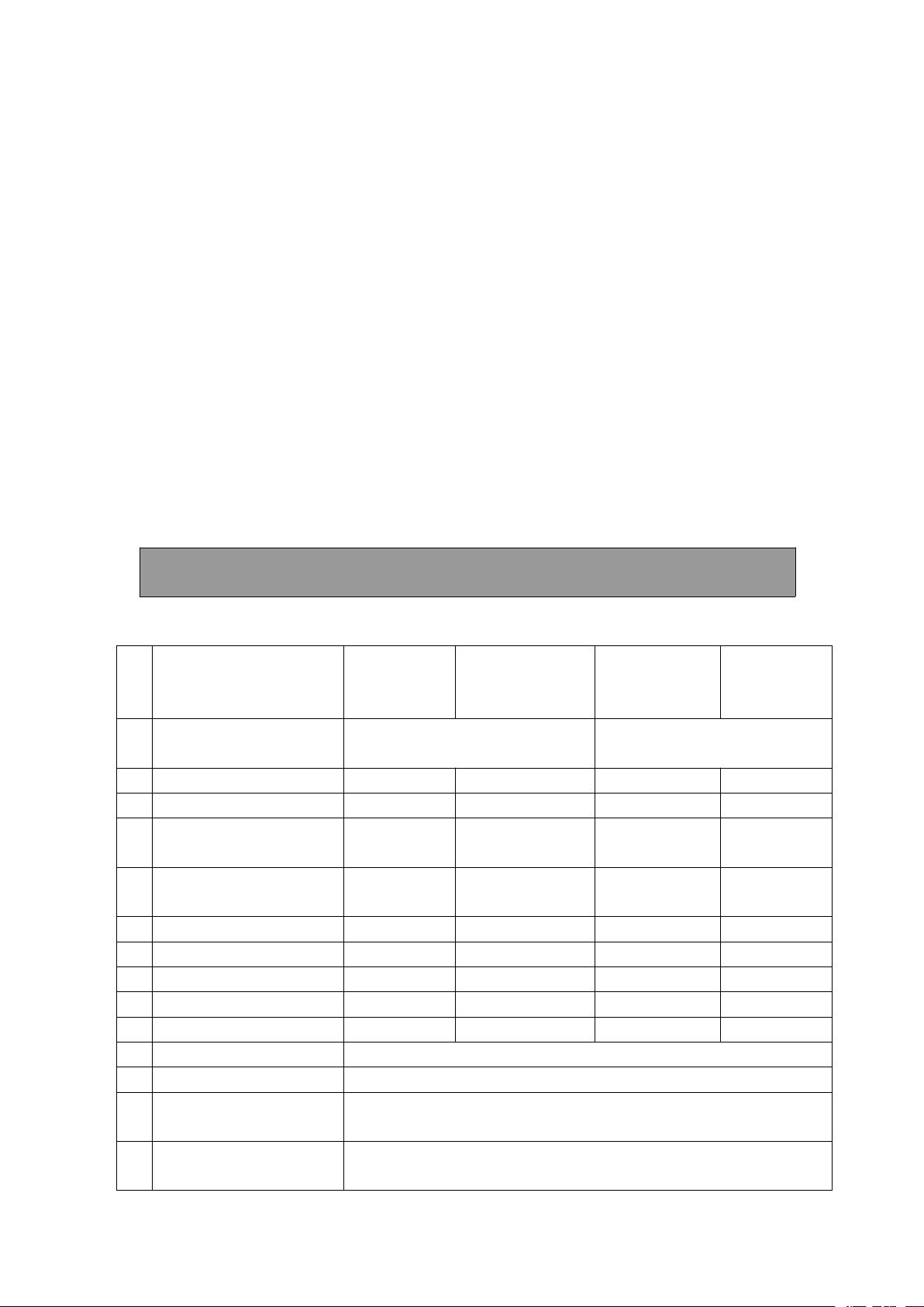
2. Back panel
Back panel of welding machine is as figure 7 below:
Figure 7: Back panel
1. Automatic air switch
This switch will automatically power off when welding machine is over-load or
broken. The switch is turn on in general and it is can’t use as power switch.
10
2. Power source input cable
Yellow and green wire should earth and other wires connect with single-phase or
3-phase input power as requirements.
3. Heater output socket(AC36V)
Connect with the CO
2
regulator.
4. Gas intake
The CO
2
gas comes in from here
5. Fan
Reduce the temperature inside welding machine.
Technical data
Main technical parameter
NO
Model
NBC-200
MIG-200Y
NBC-250
MIG-250Y
NBC-270
MIG-270Y
NBC-315Y
MIG-315Y
01
Input
voltage/frequency
AC220V±15%50/60HZ
AC380V±15%50/60HZ
02
Rated input power
8.2KVA
8.7KVA
10.1KVA
11.4KVA
03
Rated duty cycle
60%
60%
60%
60%
04
Adjustable range of
output current
50
~
200A
50
~
250A
50
~
270A
50
~
300A
05
Adjustable range of
output voltage
16.5~24V
16.5~26.5V
16.5~28V
16.5~29V
06
Open circuit voltage
58V
58V
68V
68V
07
Power
≥85%
≥85%
≥85%
≥85%
08
Power factor
≥0.93
≥0.93
≥0.93
≥0.93
09
Wire diameter
Ф0.8~Ф1.0
Ф0.8~Ф1.2
Ф0.8~Ф1.2
Ф0.8~Ф1.2
10
Weight
20kg
20kg
30kg
30kg
11
Type of wire feeder
Built-in
12
CO
2
regulator
15-20L/min
13
Main transformer
insulation grade
H
14
Output reactor
insulation grade
B

11
Maintenance
Customer can resolve conmen troubles according to the following guide.
1. Attentions and caution
1) Use suitable input power supply or will damage the element inside.
2) Welding cable and output terminal should be firmly tightened or may cause unstable
welding and connector damage.
3) To avoid output short circuit, bare parts of welding cable connect with output terminal
cannot contact with other metal.
4) Welding cable and control cable can not be damaged and broken
5) Avoid laying the heavy things on welding machine to cause the welding machine out of
shape.
6) Be sure good ventilation
2. Periodical inspection and maintenance
1) Only qualified people are allowed to clean the welding machine by compressed air and
inspect if there is any part needs tighten every 3 to 6 months.
2) Inspect if the cable is broken, the adjusting knob is loose and the element on panel is
damaged usually.
3) Contact tip and wire feeder rollers should be replaced on time and the wire feeder soft pipe
should be clean periodically.
3. Usual troubles and trouble shooting
4. a. Please do the following before repairing
1) Whether the switches on front panel are on the right position.
2) Single-phase voltage value should be between 187 and 253.
3) Please check whether 3-phase voltage is between 340V~420v or any phase is lacking.
4) Whether the input cable is correctly connected
5) Whether the earth cable is correctly and firmly connected.
6) Whether welding cable is well and correctly connected.
7) Please check whether the gas flows well and CO2 regulator is in good condition.
Attention: there is 600V high voltage inside welding machine, it is forbidden to open the case.
Please cut off all power before repairing.
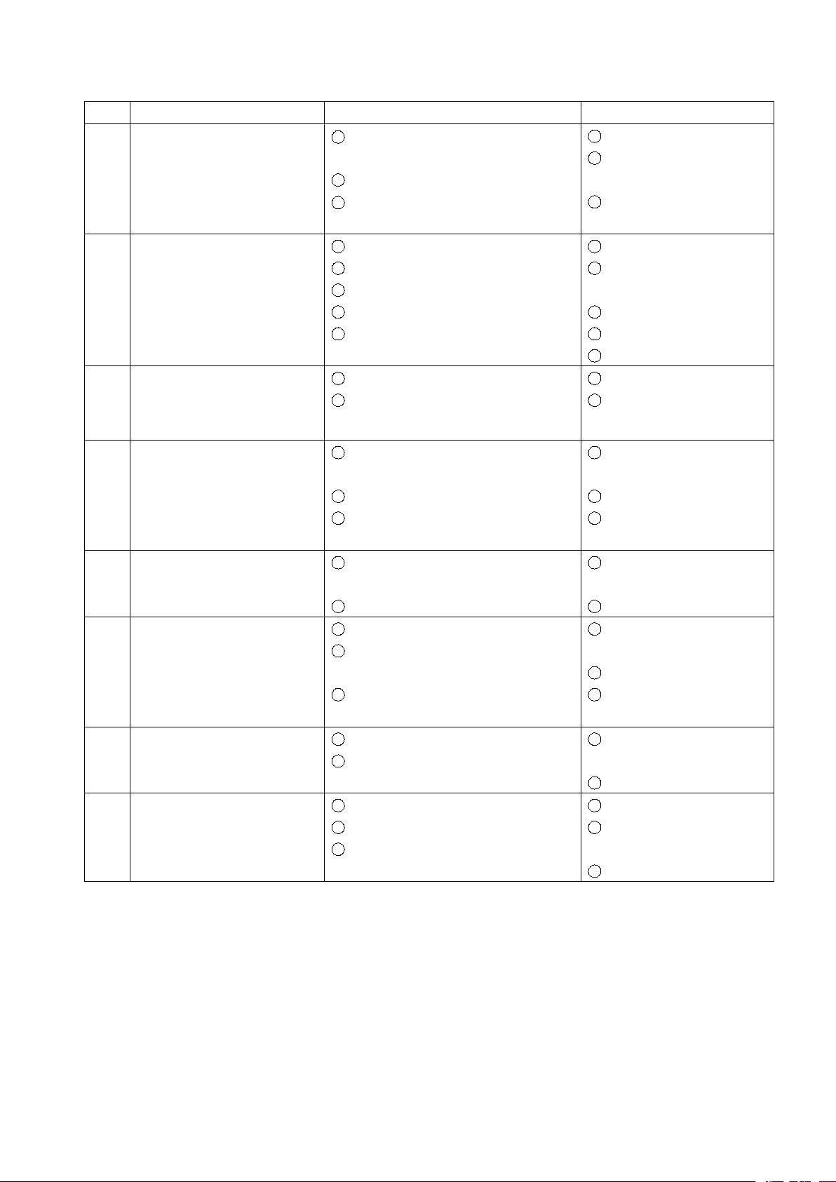
b. Common troubles and trouble shootings
Attachment A
12
NO.
Trouble
Reason
Solve
01
After turn on the power,
the indicator will not light
up
1 The 3 phase power source may
lack the phase
2 Automatic air switch is broken
3 The fuse is burnt
1 Inspect the power source
2 Replace the auto air
switch
3 Replace the fuse (2A )
with new one
02
After turn on the power, the
automatic air switch turn off
automatically
1 Auto air switch doesn’t work
2 IGBT is broken
3 3-phase bridge is broken
4 Piezoresistor is broken
5 Control board is broken
1 Replace auto air switch
2 Replace IGBT module
and trigger board
3 Replace 3-phase bridge
4 Replace piezoresistor
5 Replace control board
03
Automatic air switch on the
back panel turn off
automatically while welding
1 Over-load working a long time
2 Auto air switch is broken
1 Don’t over-load work
2 Replace the air switch
04
Welding current is not
adjustable
1 The controller or control cable of
wire feeder is broken
2 Control board is broken
3 Wire on each side of current
diverter is broken
1 Replace controller or
control cable
2 Replace control board
3 Reconnect the broken
wire
05
Unstable arc and high spatter
1
Incorrect selecting of welding
process
2
Contact tip is badly abrasion
1
Regulate the welding
process
2
Replace contact tip
06
CO
2
gas regulator cannot heat
up
1
CO
2
gas regulator is damaged
2
Heater cable is open circuit or short
circuit
3
Thermal resistor on heater is broken
1
Replace CO
2
gas
regulator
2
Repair heater cable
3
Replace the thermal
resistor
07
Push down welding gun
switch, wire feeding is
normal but no gas
1
Control board is broken
2
Magnetic valve is broken
1
Take another control
board
2
Replace magnetic valve
08
Push down welding gun
switch, wire feeder does not
work and no no-load voltage
here
1 Welding gun switch is broken
2 Wire feeder control cable is broken
3 Control board is broken
1 Replace welding gun
2 Repair wire feeder
control cable
3 Take a new control board
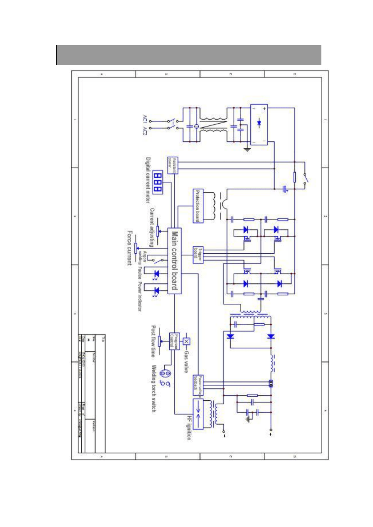
13
Electric circuit diagram