Loading ...
Loading ...
Loading ...

48 en | RE3-BPT bodypack transmitter RE3 UHF Wireless
02-2023 | 05 | F.01U.362.808
User Manual
Electro-Voice
ID Item Description, usage, and notes
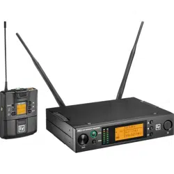
15 4-pin mini jack This is the audio input jack where the audio input device (lavalier
or headworn microphone, or instrument cable) connects to the
transmitter.
16 Belt clip Using its spring action, this clip secures the transmitter to a belt,
waistband, or other stable location.
9.2 LCD display
MHz
a
b
c
d
e
f
g
h
ID Item Description, usage, and notes
a RF power icon The RF power indicator is always visible.
Indicates RF power is set to low.
Indicates RF power is set to high (band specific).
b Battery status icon Indicates battery life.
= between 40% and 100% charge remains.
= between 20% and 39% charge remains.
= between 10% and 19% charge remains.
= below 10% charge remains.
bAttLo appears on the display and the empty cell icon begins
flashing when batteries are nearing empty.
c Frequency in MHz The first portion of the tuned frequency to the left of the
decimal in millions when the transmitter home screen is set to
Freq. If screen is set to display Group/Channel, this screen area
will display current group number.
d Frequency in kHz The second portion of the tuned frequency to the right of the
decimal in thousands when the transmitter home screen is set
to Freq. If screen is set to display Group/Channel, this screen
area will display current channel number.
e Keylock icon Indicates transmitter is in lock mode.
f MHz Image is visible the transmitter home screen is set to Freq.
Image does not appear when the transmitter home screen is set
to Group/Channel.
Loading ...
Loading ...
Loading ...
