Distributed by:
Perfect Aire, LLC
5401 Dansher Rd.
Countryside, IL 60525
844-4PA-AIRE | 844-472-2473
www.perfectaire.us
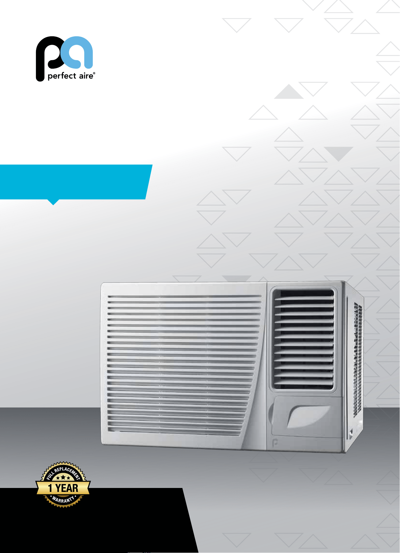
WINDOW
AIR CONDITIONER
FOR MODEL:
2PAHP18002
WITH HEAT PUMP
Before using your air conditioner, please
read this manual carefully and keep it for
future reference, along with your receipt.
Specification and performance data is subject to change without notice.
Printed in China
PA/User_2PAHP18002/11212017
USER MANUAL

For your own records, please attach a copy of your sales receipt to this manual and complete the following:
Model Number: _____________________________________ Serial Number: _______________________________________
Purchase Date: ____________________________________ Store Purchased: _____________________________________
Installation Date: ___________________________________ Installation Co.: _______________________________________
Installer Name: _____________________________________ Installer Phone No.: ___________________________________
CONSUMER PRODUCT INFORMATION
SAFETY PRECAUTIONS ...................................................................1
IMPORTANT SAFETY INSTRUCTIONS ...........................................3
PARTS DIAGRAM ..............................................................................4
BEFORE INSTALLING .......................................................................5
PREPARING FOR INSTALLATION ...................................................6
CABINET INSTALLATION .................................................................7
INSTALLATION INSTRUCTIONS .....................................................9
CONTROL PANEL .............................................................................10
REMOTE CONTROL .........................................................................11
CARE & CLEANING ..........................................................................14
TROUBLESHOOTING ....................................................................... 15
CONTENTS
This manual provides the information needed for proper use and maintenance
of this air conditioner. Basic preventative care can help extend the life of
this unit. The “Troubleshooting” section in this manual contains a chart with
solutions to the most common problems. Referring to this section may save
time and prevent the need for a service call in the event of a problem.
CAUTION
● Contactanauthorizedservicetechnicianforrepairormaintenanceofthisunit.
● Contactaninstallerforinstallationofthisunit,ifnecessary.
● Theairconditionerisnotintendedforusebyyoungchildrenwithoutadultsupervision.Youngchildrenshouldbe
supervised to ensure that they do not play with the air conditioner.
● Disabledpersonsmayrequireassistancewithsetup.
● Ifthepowercordistobereplaced,replacementworkshouldbeperformedbyauthorizedpersonnelonly.
● Installationandrepairworkmustbeperformedinaccordancewiththenationalwiringstandardsbyauthorized
personnel only.
● Donotoperateyourairconditionerinawetroomsuchasabathroomorlaundryroom.
NOTE: All the illustrations in this manual are for explanation purposes only. Unit purchased may be
slightlydierent.
Thedesignandspecicationsaresubjecttochangewithoutpriornoticeforproductimprovement.Contactcustomer
service for details.
1
WARNINGS
Plug in power cord properly. Failuretodosomaycauseelectricshockorredueto
excess heat generation.
DO NOT operate or stop the unit by inserting or pull-
ing out the power plug directly from the wall.
Doingsomaycauseelectricshockorredueto
heat generation
DO NOT use a damaged power cord.
Doingsomaycauseelectricshockorre.Ifthepower
cord is damaged, it must be replaced by the manufactur-
eroranauthorizedservicecenterorasimilarlyqualied
personinordertoavoidahazard
DO NOT modify power cord length or share the
outlet with other appliances.
Doingsomaycauseelectricshockorredueto
heat generation.
DO NOT operate with wet hands or in
damp environment.
Doingsomaycauseelectricshock.
DO NOTdirectairowdirectlyatroomoccupants.
This could cause health issues.
Alwaysensureeectivegrounding. Incorrectgroundingmaycauseelectricshock.
DO NOT allow water to run into electric parts.
Doingsomaycausefailureofmachineorelectricshock.
Alwaysinstallcircuitbreakerandadedicated
power circuit.
Incorrectinstallationmaycausereandelectricshock.
Always unplug the unit if strange sounds, smell or
smokecomesfromtheunit.
Failuretodosomaycausereandelectricshock.
DO NOTusethesocketifitislooseordamaged.
Doingsomaycausereandelectricshock.
DO NOT open the unit during operation.
Doingsomaycauseelectricshock.
DO NOTuserearmsnearunit.
Doingsomaycausere.
DO NOT use the power cord close to
heating appliances.
Doingsomaycausereandelectricshock.
DO NOT disassemble, modify, or drill holes into
the air conditioner.
Doingsomaycausefailureandelectricshockandvoid
manufacturer's warranty.
Ventilate room before operating air conditioner if
thereisagasleakfromanotherappliancesuchas
a stove.
Failuretodosomaycauseexplosion,reandburns.
DO NOT
usethepowercordnearammablegasor
combustibles,suchasgasoline,benzene,thinner,etc.
Doingsomaycauseanexplosionorre.
READ SAFETY PRECAUTIONS BEFORE INSTALLATION
Topreventinjurytotheuserorotherpeopleandpropertydamage,thefollowinginstructionsmustbefollowed.
Incorrectoperationduetoignoringofinstructionsmaycauseharmordamage.Theseriousnessisclassiedbythe
following indications.
THIS SYMBOL INDICATES THAT IGNORING INSTRUCTIONS MAY CAUSE
DEATH OR SERIOUS INJURY.
NEVER DO THIS.OTHER SYMBOLS: ALWAYS DO THIS.
THIS SYMBOL INDICATES THAT IGNORING INSTRUCTIONS MAY CAUSE
MODERATE INJURY TO YOUR PERSON, OR DAMAGE TO YOUR UNIT OR
OTHER PROPERTY.
SAFETY PRECAUTIONS
2
CAUTIONS
Whenremovingairlter,DO NOT touch metal parts of
the unit.
Doingsomaycauseaninjury.
DO NOT clean with water.
Water may enter the unit and degrade the insulation
causinganelectricshock.
Ensure proper ventilation especially in rooms with a
stove or other appliances.
Failure to do so may result in an oxygen shortage.
Unitandcircuitbreaker/fusemustbeswitchedOFF
when cleaning.
CleaningunitwhenpowerisONmaycausereand
electricshockandmaycauseaninjury.
DO NOT put a pet or house plant where it will be ex-
posedtodirectairow.
Thiscouldinjurethepetorplant.
Use ONLY as intended. This unit is NOT intended to preserve precision devic-
es,food,pets,plants,andartobjects.Itmaycause
deteriorationofquality,etc.
Stop operation and close the window in severe
storms or hurricanes.
Operationwithwindowsopenmaycausemoistureto
enter the room.
Hold the plug by the head of the power plug when
takingitout.
Failuretodosomaycauseelectricshock
and damage.
If unit will not be used for a long period of time, un-
plugorturnOFFmainpowerswitch.
Leavingpoweronmaycauseunitfailureorre.
DO NOT place obstacles around air-inlets or inside of
air-outlet.
Obstaclesmaycauseappliancefailureoraccident.
Periodicallycheckinstallationbracketfordamage. Prolonged exposure to outdoor elements may cause
damagetoinstallationbracketcausingunittofall.
Alwaysinsertlter(s)securely.Cleanlter(s)AT
LEASTonceeverytwoweeks.
Operationwithoutsecured,installedltersmay
causefailure.Adirtyltercancausetheunittonot
runeciently.
Use only a soft cloth to clean the unit. Cleaners or detergents may change the color or
scratch the surface of the unit.
Usecautionwhenunpackingandinstalling. Sharpedgescouldcauseinjury.
NEVERdrinkwaterdrainedfromairconditioner.
Water from unit contains contaminants and could
cause illness.
DO NOTplaceheavyobjectsonthepowercordand
always ensure that the cord is not compressed.
Thereisdangerofreorelectricshock.
If water enters the unit's electrical components, turn
theunitoatthepoweroutletandswitchothecir-
cuitbreaker.Isolatesupplybytakingthepower-plug
outandcontactaqualiedservicedtechnician.
Thereisdangerofelectricshock.
3
IMPORTANT SAFETY INSTRUCTIONS
NOTE
:
The power supply cord with this air
conditioner contains a current detection
devicedesignedtoreducetherisk
ofre.Pleaserefertothesection
“OperationofCurrentDevice”(below)
for details. In the event that the power
supply cord is damaged, it cannot be
repaired. It must be replaced by an
authorizedrepairtechnicianwithacord
from the Product Manufacturer.
WARNING
Avoidrehazardsorelectricshock.
DO NOT use an extension cord or an
adapter plug. DO NOT remove any prong
from the power cord.
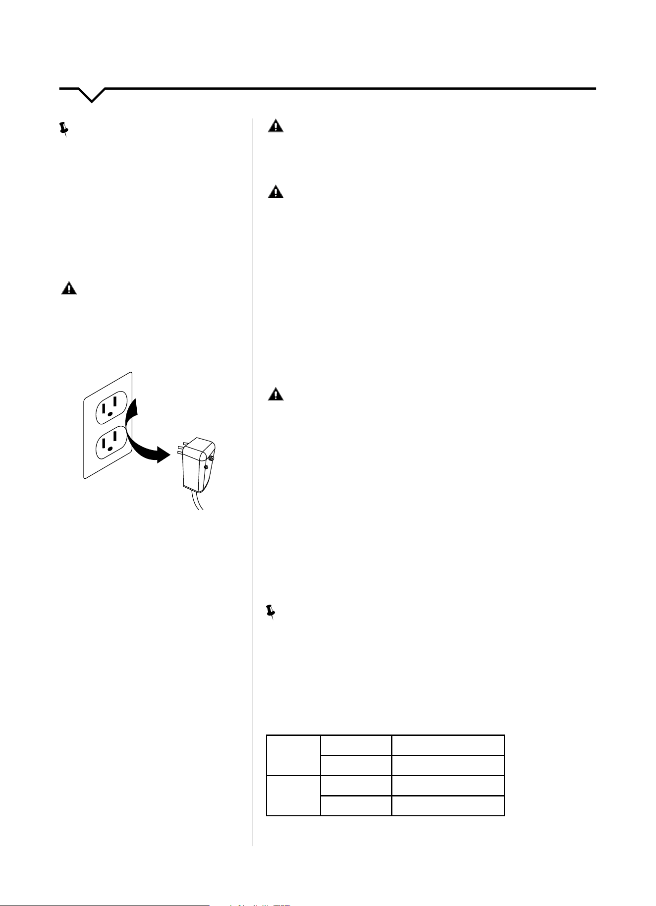
OPERATION OF
CURRENT DEVICE:
The power supply cord contains a
current device that senses damage
to the power cord. To test your power
supply cord, do the following:
1. Plug in the air conditioner.
2. The power supply cord will have
TWObuttonsontheplughead.Press
theTESTbutton.Youwillnoticea
clickastheRESETbuttonpopsout.
3. Press the RESET button. Again,
youwillnoticeaclickasthe
button engages.
4. The power supply cord is now
supplyingelectricitytotheunit.(On
some products this is also indicated
byalightontheplughead.)
WARNING
FORYOURSAFETY:Donotstoreorusegasolineorotherammable
vaporsandliquidsinthevicinityofthisoranyotherappliances.
WARNING - PREVENT ACCIDENTS
Toreducetheriskofre,electricalshock,orinjurytopersonswhenusing
your air conditioner, follow basic precautions, including the following:
● Besuretheelectricalserviceisadequateforthemodelyouhave
chosen. This information can be found on the serial plate, which is
located on the side of the cabinet and behind the grille.
● Iftheairconditioneristobeinstalledinawindow,youwillwantto
cleanbothsidesoftheglassrst.Ifthewindowisatriple-track
type with a screen panel included, remove the screen completely
before installation.
● Besuretheairconditionerhasbeensecurelyandcorrectlyinstalled
according to the installation instructions in this manual.
●
Save this manual for possible future use in removing or installing this unit.
● Whenhandlingtheairconditioner,becarefultoavoidcutsfromsharp
metalnsonfrontandrearcoils.
WARNING - ELECTRICAL INFORMATION
The complete electrical rating of your new room air conditioner is
statedontheserialplate.Refertotheratingwhencheckingthe
electricalrequirements.
● Besuretheairconditionerisproperlygrounded.Tominimizeshock
andrehazards,propergroundingisimportant.Thepowercordis
equippedwithathree-pronggroundingplugforprotectionagainst
shockhazards.
● Yourairconditionermustbeusedinaproperlygroundedwall
receptacle.Ifthewallreceptacleyouintendtouseisnotadequately
groundedorprotectedbyatimedelayfuseorcircuitbreaker,havea
qualiedelectricianinstalltheproperreceptacle.
● Ensurethereceptacleisaccessibleaftertheunitinstallation.
● DO NOT run air conditioner without side protective cover in place. This
could result in mechanical damage within the air conditioner.
● DO NOT use an extension cord or an adapter plug.
NOTE
:
DO NOTusetheplugtoturntheunitonoro.
● AlwaysmakesuretheRESETbuttonispushedinforcorrectoperation.
● ThepowersupplymustbereplacedifitfailsresetwheneithertheTEST
button is pushed or it cannot be reset.
● Ifpowersupplycordisdamaged,itcannotberepaired.Pleasecall
Consumer Services at 844-472-2473 to assist with replacement.
NOTE: This air conditioner is designed to be operated under the
following conditions:
Cooling
Operation
Outdoor Temp:
64–109°F/18–43°C
Indoor Temp:
61–86°F/16–30°C
Heating
Operation
Outdoor Temp:
19–84°F/-7–29°C
Indoor Temp:
32–80°F/0–27°C
Performance may be reduced outside of these operating temperatures.
Grounding Type
Wall Receptacle
Do not, under any
circumstances, cut,
remove, or bypass the
ground prong.
Power supply cord
with 3-prong grounding
plug and current
detection device
4
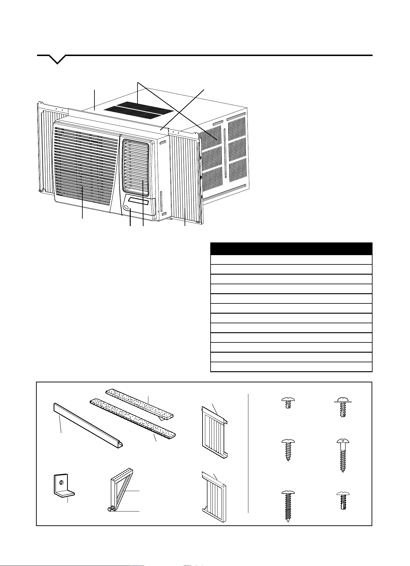
PARTS DIAGRAM
UNPACKING THE UNIT
Unpackandvisuallyinspecttheunit.Reportany
damage to the delivering carrier immediately. Remove
anddiscardallpackingmaterial.
Before installing, please ensure you have all installation
parts/accessoriesincludedwiththisunit.(Seeliston
right.Drawingsofthesepartsarealsoshownbelow.)
If missing parts, please contact Consumer Services at
844-4PA-AIRE(844-472-2473).
1. CABINET
2. AIR INLET
3. TOP RAIL
4. SLIDING ACCORDION PANEL
5. LOUVERS
UP/DOWN ADJUSTMENT
Holdtheup/downairapand
manually move it upward or
downward to your desired position.
LEFT/RIGHT ADJUSTMENT
(swingfunction)
6. CONTROL PANEL
7. FRONT GRILLE (Airlterislocated
behindthefrontgrille)
NOTE: All illustrations in this manual
are for explanation purposes only. Unit
purchasedmaybeslightlydierent.
ITEM NAME OF PART QTY
A Accordion Panel Screws 6
B Top Rail Screws 4
C V-Support & Front Panel Screws 7
D Wood Screws 6
E Cabinet Screws 4
F Front Panel Screws 2
G WindowLockingBracket 2
H V-Support with Nut & Bolt 2
I Accordion Panels 2
J
Top Mounting Rail 1
K
Window Sash Seal 1
L
FoamTopWindowGasket 1
1
2
3
456
7
K: Window Sash Seal I: Left Accordion
Panel
I: Right Accordion
Panel
L: Foam Top
Window Gasket
J: Top
Mounting Rail
H: V-support (2)
H: Bolt (2) & Nut (2)
G: Window Locking
bracket (2)
TYPE A (6):
Accordion Panel Screws
TYPE B (4):
Top Rail Screws
TYPE C (7): V-Support &
Front Panel Screws
TYPE D (6):
Wood Screws
TYPE E (4):
Cabinet Screws
TYPE F (2):
Front Panel Screws
5
BEFORE INSTALLING
BEFORE YOU BEGIN
Read these instructions completely and carefully.
IMPORTANT- Save these instructions.
IMPORTANT-Observeallgoverningcodes
and ordinances.
Note to Installer- Be sure to leave these instructions with
the Consumer.
Note to Consumer- Keep these instructions for
future reference.
Skill level-Installationofthisappliancerequiresbasic
mechanicalskills;professionalinstallationpreferred.
Completion time- Approximately 1 – 1½ hours.
We recommend that two people install this product.
Proper installation is the responsibility of the installer.
Product failure due to improper installation is not
covered under the Warranty.
YouMUSTuseallsuppliedpartsanduseproper
installation procedures as described in these
instructions when installing this air conditioner.
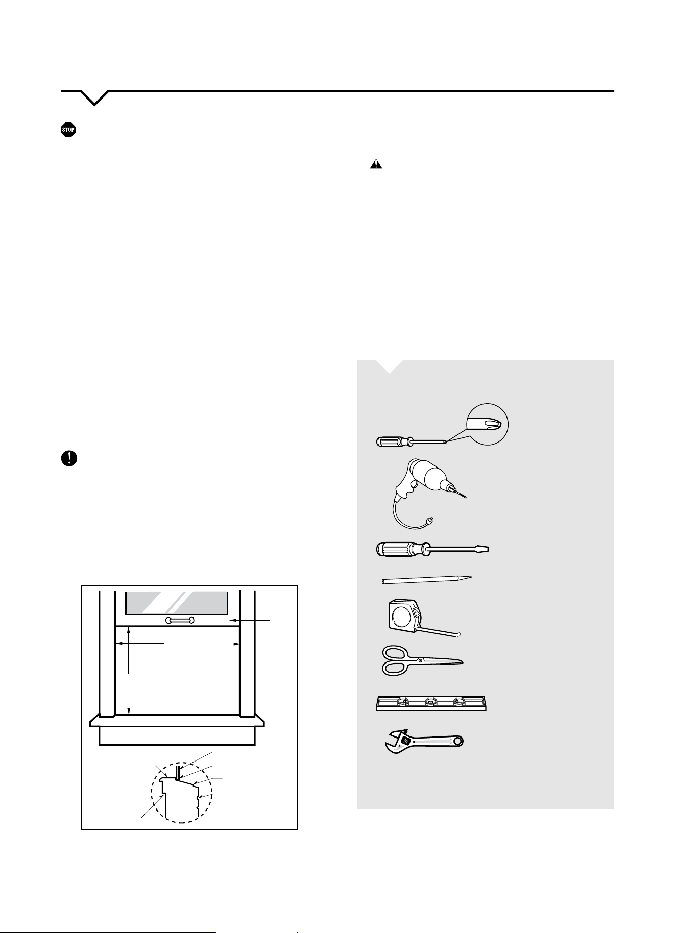
INSTALLATION REQUIREMENTS
This room air conditioner is designed for installation in
standard double-hung windows with actual opening
widthsof30in.to38in.(min.of26in.withoutpanels).
Lower sash must open sufficiently to allow a clear
vertical opening of 17
3
/8 in. Side louvers and the rear
of the air conditioner must have clear air space to allow
enough airflow through the condenser for heat removal.
The rear of the unit must be outdoors, not inside a
building or garage.
Inner sill
Offset
Window
Sill
Exterior
Interior wall
30–38ʺ
17
³/8
ʺ
min
Sash
Checkthelocationwheretheunitwillbeinstalled.
Properinstallationisyourresponsibility.Makesureyou
have everything necessary for correct installation.
The location should provide:
• Groundedelectrical3prongoutletwithin4ft.of
where the air conditioner power cord exists.
WARNING: DO NOT use an extension cord.
• DO NOTblockthelouversonthefrontpanel.
• DO NOT blockthelouversontheoutsideofthe
air conditioner.
NOTE: Cabinet louvers must not be obstructed. Air must
be able to pass freely through the cabinet louvers.
INSTALLATION
Pickalocationwhichwillallowcoldairtoblowinto
the area you desire. Windows used for installation
must be strong enough to support the weight of the air
conditioner. Good installation with special attention to
the proper position of the unit will lessen the chance
that service will be needed.
TOOLS YOU WILL NEED
Phillips
Screwdriver
Drill&3/16ʺ
drill bit
Screwdriver
Pencil
Ruler or Tape
Measure
Scissors or
Knife
Level
Adjustable
Wrench
NOTE: Save carton and these Installation Instructions for
future reference. The carton is the best way to store unit
during winter or when not in use.
If you encounter problems during installation, call
ConsumerServicesat844-4PA-AIRE(844-472-2473).
6
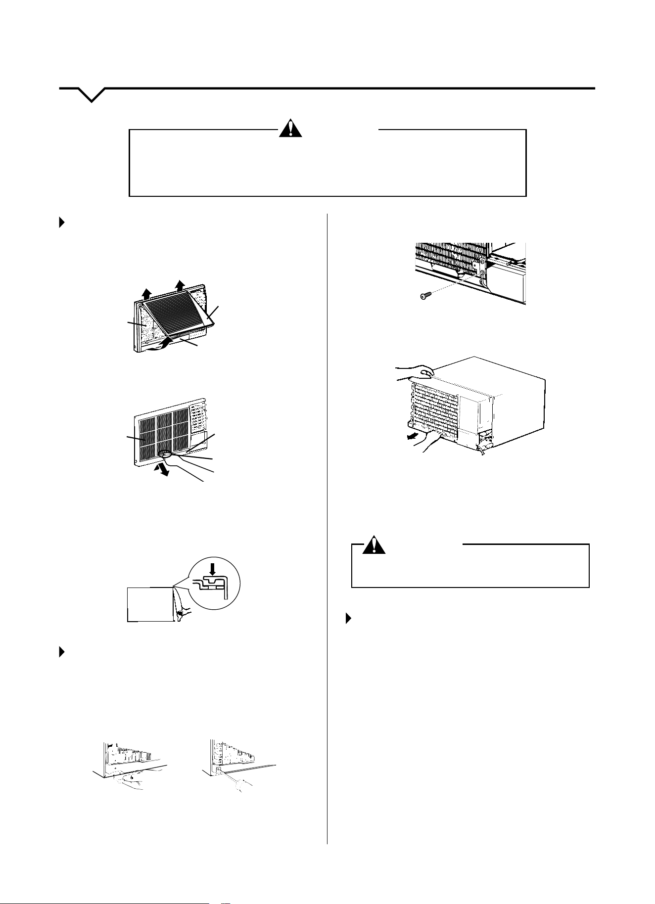
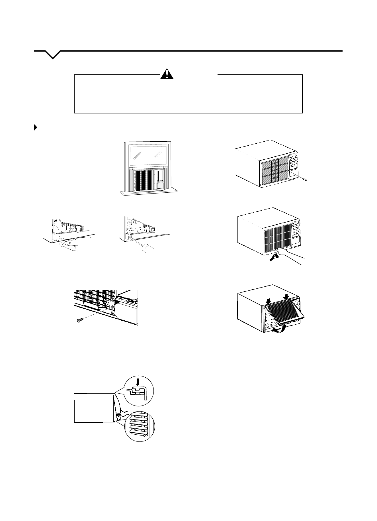
PREPARING FOR INSTALLATION
STEP 1:
SLIDE OUT CHASSIS REMOVAL
1. Locate tabs on the bottom of the front grille and
gently pull out, lift up, and slide the grille to the left.
front grille
front case
filter
2. Locatethehandleonthebottomofthelter.Gently
pull up and out to remove from the panel.
filter
front case
filter handle
3. Remove screws from the front panel and set aside to
reinstall later.
4. To remove the front panel, grab the bottom and lift up
to release.
STEP 2:
REMOVING AIR CONDITIONER FROM
THE CABINET
1. Withthefrontpanelremoved,locatethelocking
bracketandscrewfoundonthebottomleft-hand
side of the unit. Set aside to reinstall later.
2. Remove the grounding screw found on the bottom
right-hand corner and set aside to reinstall later.
3. Carefully slide the air conditioner from the cabinet by
gripping the base pan handle and pulling out.
NOTE: Do not lift, push, pull or remove any expanded
polystyrene (foam) from inside the air conditioner. It is not
packing material.
WARNING
DO NOT operate unit with shipping foam blocks in
place. Always remove prior to running unit.
STEP 3:
REMOVE PACKING MATERIALS
• Removeanddisposeoforrecycleallpackaging
materials. Remove tape and glue residue from
surfaces before turning on the air conditioner. Rub a
smallamountofliquiddishsoapovertheadhesive
withyourngers.Wipewithwarmwateranddry.
• Donotusesharpinstruments,rubbingalcohol,
ammableuids,orabrasivecleanerstoremovetape
or glue. These products can damage the surface of
your air conditioner.
• Handleairconditionergently.
WARNING
EXCESSIVE WEIGHT HAZARD!
Toreducetheriskofpersonalinjury,weadviseyouhavetheassistanceof2ormore
individuals while moving and installing the air conditioner. Failure to do so can result in
backorotherinjuries.Aroomairconditionercanweighbetween70–240lbs.
7
CABINET INSTALLATION
STEP 1:
INSTALLING TOP RAIL AND
ACCORDION PANELS
1. Locate top rail and accordion panels.
Left Panel
Right
Panel
Top Mounting Rail
2. Secure the top rail with 4 type B screws, from the
inside of the cabinet. See image below.
Top Mounting Rail
3. Insert top and then bottom of right-hand accordion
panel into top rail and bottom guide on air
conditioner cabinet.
Accordion
Panel
Top Rail
4. Extend the right-hand accordion panel outward to
inserttherstscrewthroughthemiddleholeofthe
accordion panel. Use Type A screws.
NOTE:
Thisscrewisrequiredto
correctly attach accordion
panel(toptobottom)totheair
conditioner cabinet.
5. While the right-hand accordion is still extended,
insert the Type A screws into the top and bottom
slots of accordion. Screw accordion to the top and
bottom holes in air conditioner cabinet.
6. Slide accordion panel housing into guides as far as it
will go.
7. Repeat above steps for the left accordion panel.
INNER SILL
OUTER SILL
FOR STORM WINDOWS
WOOD FOR
INNER SILL
STORM WINDOW
FRAME
WOOD
STRIP
CAUTION: Do not install this air conditioner in
a window if the bolts do not make contact with the window sill.
STEP 2:
INSTALL CABINET INTO WINDOW
• Handleairconditionergently.
• Besureyourairconditionercabinetdoesnotfallout
of the opening during installation or removal.
• Thelocationwherethepowercordexitstheair
conditioner should be no more than 4 ft from a
grounded 3 prong outlet.
• Donotblockthelouversonthefrontpanel.
• Donotblockthelouversontheoutsideoftheair
conditioner.Ifairisobstructedand/ordeectedback
into the unit, the air conditioner’s compressor may
cycleonandorapidly.Thiscoulddamagetheunit.
1. Center empty cabinet in
window.Checkthatlower
rail of air conditioner
cabinet is behind and
againstbacksideof
window sill. Maintain
armholdontheair
conditioner cabinet.
Lower window sash to
hold cabinet in place. Top
rail must be on the inside room of window sash.
2. Measure the distance between the right-hand side of
the cabinet and the inside of the window channel.
3. Repeatfortheleftside.Adjustthecabinetuntilthe
distance on each side is the same.
Window Sash
Empty Cabinet
Window Frame
4. Usea3/16ʺdrillbittodrill4starterholes1/2ʺ deep
through the 4 holes on the cabinet and into the
window sill.
BOTTOM VIEWBACK VIEW
Accordion
Panel
Bottom Guide
Window
Sash
Top
Channel
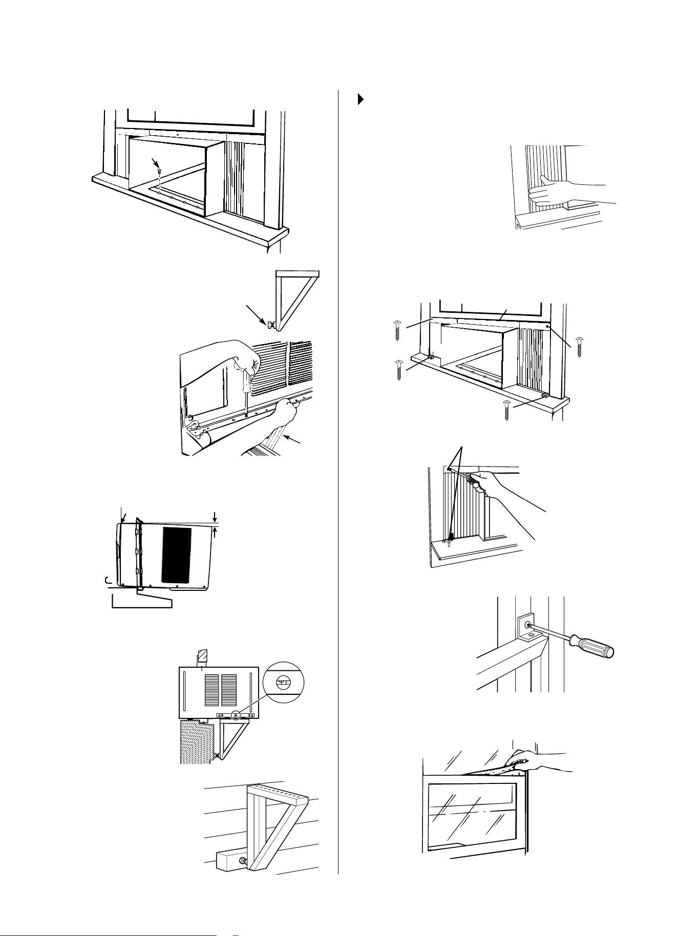
8
5. Attach cabinet to window sill with Type E screws.
4 Type E Screws
Makesurethenutsandbolts
are tightened in both the left
and right V-supports.
Position the
V-supports on the
case bottom so that
they are near the
outside wall. Attach a
V-support to each
side of the bottom
of the case using
Type C screws, 3 on
each side.
6. Checkthatairconditionercabinetistiltedto
the outside so that condensate water will run to
the outside.
Wooden Windows
INSIDE
OUTSIDE
H: Approx. 1ʺ to 1³/
8
ʺ
H
Measure from the cabinet edge
Adjustthelevelingboltsandnutsagainstoutsidewall
so that the case
has a slight tilt to
the outside. Tighten
nuts with an
adjustablewrench.
Usealevel;about
a1/2bubblewill
be the correct case
slant to the outside.
Useawoodblock
(obtainedlocally)between
the leveling bolts and the
wallifthewallisweak
or if the weight of the air
conditioner falls between
the studs in the wall.
STEP 3:
SECURING ACCORDION PANEL
TO FRAME
1. Pull left-hand accordion
panel out until it reaches
the window frame. Use a
3/32ʺ drill bit to drill a starter
hole through the hole in the
accordion panel housing and
into the lower window sash.
2. Extend the left and right
accordion panels to the vertical window sashes. Drill
pilot holes and attach the top and bottom corners
with 4 Type D screws.
Top Mounting Rail
4x Type D
Screw
Type D Screws
3. Repeat for right-hand accordion panel.
4. Attach the window
locking(G)brackets
with two Type D
screws, one on each
side.(Seediagram.)
5.
Cut the foam top
windowgaskettothe
window width.
6. Stuthefoambetweentheglassandthewindowto
prevent air and insects from getting into the room.
Nut & Bolt
Front
View
V-Support
9
INSTALLATION INSTRUCTIONS
INSTALL THE AIR CONDITIONER IN
THE CASE
1. Slide the air conditioner into
the case. Do not push on the
controlsorthennedcoils.
Makesuretheairconditioner
isrmlyseated.
2. Reinstallthelockingbracketandscrew
removed earlier.
3. Reconnect the ground wire to the air conditioner
using the screw removed earlier.
IMPORTANT: The ground wire must be reinstalled to
ensure a proper ground.
4. Attach the front grille frame to the case by inserting
the tabs on the grille frame into the slots on the front
top of the case. Push the grille frame in and install
the 2 Type F screws at bottom left and right side of
front panel.
Guide the lever carefully
through the grille frame
as you push it in.
5. Secure the front grille frame to the case with one
Type C screw.
6. Reinstallthelter.
7. Reinstall the inlet grille. Connect power.
IMPORTANT:
• Ifyouturnotheairconditioner,waitatleast3
minutesbeforeturningitbackon.Thisprevents
the air conditioner from blowing a fuse or tripping a
circuitbreaker.
• Donottrytooperateyourairconditionerinthe
cooling mode when outside temperature is below
61°F(16°C).Donottrytooperateyourair
conditioner in the heating mode when outside
temperatureisover86°F(30°C).Theinside
evaporatorcoilwillfreezeup,andtheairconditioner
will not operate properly.
NOTE: In the event of a power failure, your air
conditioner will operate at the previous settings when
the power is restored.
WARNING
EXCESSIVE WEIGHT HAZARD!
Toreducetheriskofpersonalinjury,weadviseyouhavetheassistanceof2ormore
individuals while moving and installing the air conditioner. Failure to do so can result in
backorotherinjuries.Aroomairconditionercanweighbetween70–240lbs.
10
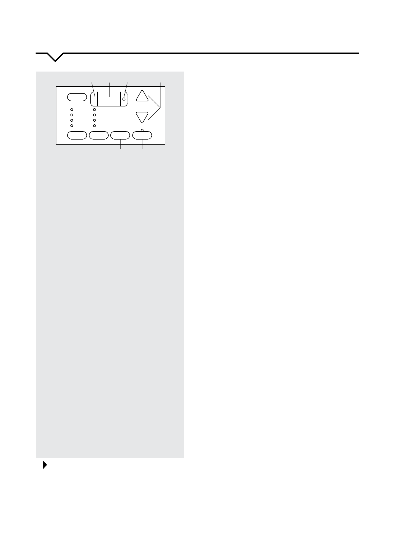
CONTROL PANEL
HEAT Mode
• PresstheMODEbuttonuntiltheHEATindicatorison.
• PresstheTEMP/TIMEbuttons(+/–)toadjustdesired
room temperature on the display.
• PresstheSPEEDbuttontoselectdesiredfanspeed
(High,Med,Low,Auto).
FAN Mode
Use this mode to circulate the air in the room without
cooling or dehumidifying the room. In FAN mode, the
temperaturecannotbeadjusted.
• PressthemodebuttonuntiltheFANindicatorison.
• PresstheSPEEDbuttontoadjustthefanspeed(High,
Med,Low).Whenusingthecontrolpanel,AUTOfan
speedcannotbeselected.AUTOfanspeedcanbe
selected with the remote only.
ENERGY SAVER Mode
WhiletheunitisrunningpresstheMODEbuttontoselect
ENERGYSAVER. When the set temperature is reached
thecompressorwillshuto.Thefanwillcontinuetorun
3minutesafterthecompressorshutso.Theunitwillnot
run for 10 minutes. After 10 minutes the fan will run for 1
minute and repeat the cycle. If the temperature changes the
compressor will turn on until the set temperature is reached.
SWING Function
• Underswingstatus,pressSWING button to cancel swing
function;undernon-swingstatus,pressSWING button to
set swing function.
• Ifsettingswingfunctionwhenthefanisoperating,the
swing motor will operate.
• Iftheunitisswingingunderheat-blowingstatus,swing
and the fan will operate simultaneously. If the fan is at
OFFstatus,swingfunctioncannotbestartedupevenby
pressing the SWING button.
TIMER ON/OFF Function
TIMER ON
• Turntheunitontosetthedesiredtemperatureandfan
speed for when the unit turns on with the Timer.
• Turntheunito(Standby).
• PresstheTIMERbutton
• PresstheTEMP/TIMERbuttons(+/–)tosetthetimeon
thedisplayfrom0.5–24hours(by0.5hourincrementsup
to24hours).
• TheTIMERON/OFFindicatorwillbeonwhenthetimer
has been set.
TIMER OFF
• Turntheunitontosetthedesiredtemp.andfanspeed.
• PresstheTIMERbutton.
• PresstheTEMP/TIMERbuttons(+/–)tosetthetimeon
thedisplayfrom0.5–24hours(by0.5hourincrementsup
to24hours).
• TheTIMERON/OFFindicatorwillbeonwhenthetimer
has been set.
NOTE:
To cancel the timer function press the TIMER button again.
Lights next to the touch pads on the control
panel indicate the selected settings. The display
shows the set temperature when in HEAT/COOL/
ENERGYSAVER modes. The display shows time
remaining on the delay timer. It shows the room
temp. when in FAN only mode.
1. POWER Button
PresstoturntheunitON/OFF.
2. REMOTE CONTROL SIGNAL RECEIVER
•Makesuresignalreceiverisunobstructed.
•Maximumremotedistanceis26ft.
•Unitwillbeepwhensignalfromremotehas
been received.
3. DIGITAL DISPLAY
•InFANmode,thisdisplaystheroomtemp.
•InCOOLandHEATmode,thisdisplaysthe
set temperature.
•InTIMERfunction,On/Otimeisdisplayed.
•IfDisplayshowsErrorCodes,contact
Consumer Services at 844-472-2473.
4. SET Indicator
Light indicates the unit is in the temperature
or delay time set mode.
5. TEMP/TIMER Buttons +/–
Presstoadjustthetemperatureandsetthe
timefortheOnorOtimer.Pressboth+and
– at the same time to switch from °C and °F.
6. TIMER ON/OFF Indicator
IlluminateswhentimerhasbeensetforOn
and/orO.
7. TIMER Button
PresstosetthetimerOn/O.
8. SWING Button
Presstoautomaticallyswingnsleftandright.
9. MODE Button
PresstoselectHEAT,COOL,ENERGY
SAVER or FAN.
10. FAN SPEED Button
PresstoselectLOW,MED,HIGHorAUTO
fan speed.
USING THE CONTROL PANEL
COOL Mode
• PresstheMODEbuttonuntiltheCOOL
indicator is on.
• PresstheTEMP/TIMEbuttons(+/–)toadjust
desired room temperature on the display.
• PresstheSPEEDbuttontoselectdesiredfan
speed(High,Med,Low,Auto).
1 2 5
7
6
3 4
8
910
Set
+
-
TIMER
MED
HIGH
LOW
AUTO
POWER
FAN
SPEED
MODE
COOL
ENERGY SAVER
FAN ONLY
HEAT
0.5-24 HR
TEMP/TIMER
SWING
11
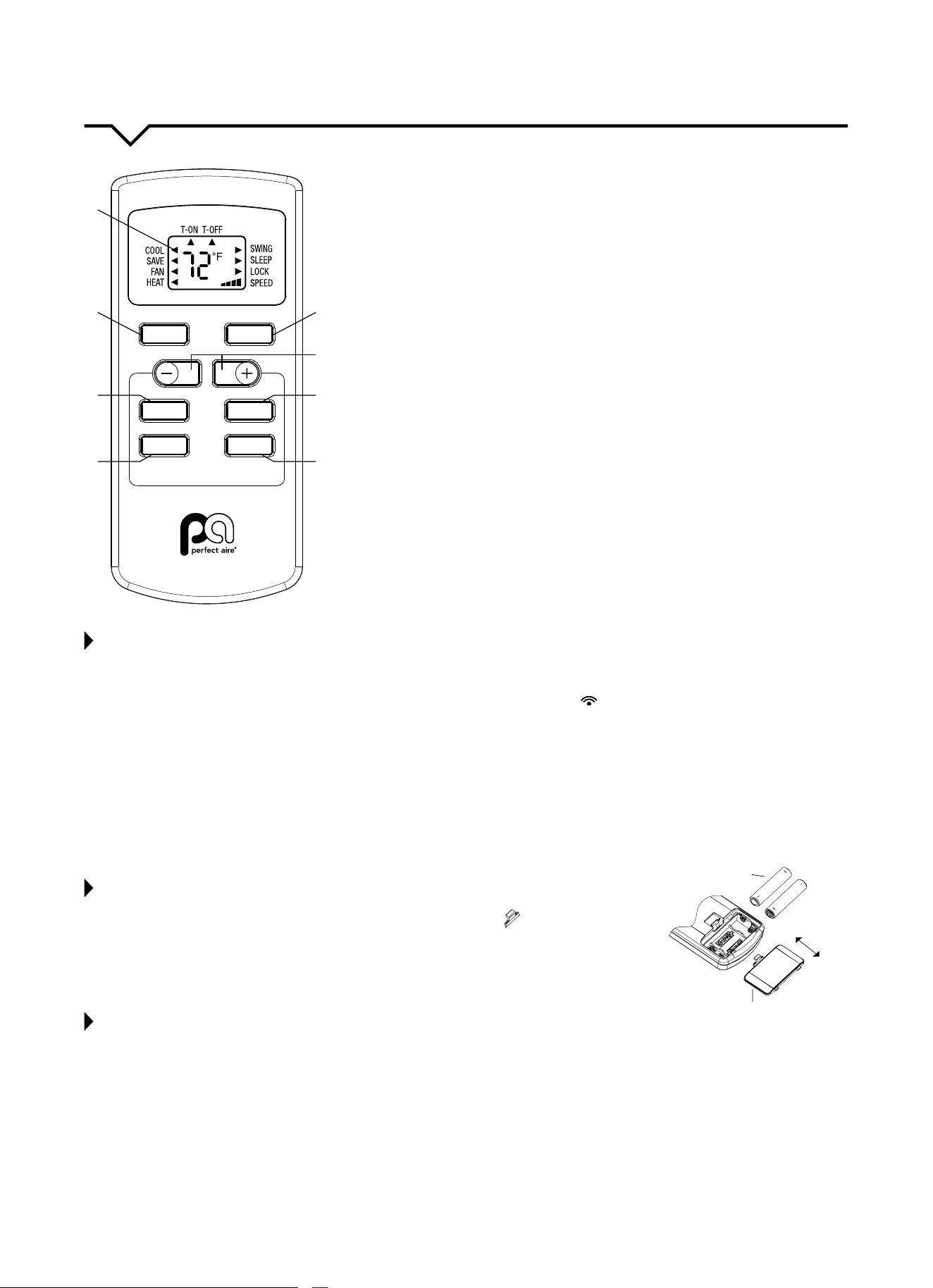
REMOTE CONTROL
1. ON/OFF Button
PresstoturntheunitON/OFF.
2. DIGITAL DISPLAY
3. MODE Button
Press this button to select operating mode.
4. +/– BUTTONS
Thesebuttonsareforincreasing/decreasingthetemperature
settingswithinarangeof61–86°F(16–30°C)andforsettingthe
time when setting the Timer.
5. SWING Button
Presstoautomaticallyswingnsleftandright.
6. TIMER Button
PressthisbuttontosettheTimerfortimeSwitch-On,Switch-O
ortocancelthetimer.(Seepage13formoreinformation.)
7. SLEEP Button
Available on remote control only. See page 13.
8. FAN Button
Press this button to select your fan speed.
NOTES ABOUT USING THE REMOTE CONTROL
• Somefunctionsmaynotbeavailableforthisunit.Ifselected,unitwillcontinuetorunwithnochange.
• Whentheunitispoweredo,youcanoperatetheairconditionerwiththeremotecontrol.
• Eachtimeyoupressthebuttontheremotecontrol,thesendingsignalicon“ ”ontheremotewillblinkonce.Iftheair
conditioner beeps, it means the signal has been received.
• Whenunitiso,settemperaturewillbedisplayedontheremotecontrol.Whenunitison,itwilldisplaytheiconofthe
on-going function.
• DO NOT place the remote near anything with high temperature such as an electric heating pad or radiator.
• DO NOT place the remote where it is exposed to direct sunlight or strong lights.
• DO NOT drop anything on the remote as this may cause damage.
• DO NOTblocktheareabetweentheunitandremoteoritwillnotreceivesignalsfromtheremote.
• DO NOTsplashwaterorotherliquidsontotheremote.
• DO NOTplaceheavyobjectsontheremote.
REPLACING THE BATTERIES
1. Pressthebacksideofremotecontrolonthespotmarkedwith“ ”, and then push out
the cover of battery box along the arrow direction.
2. ReplacetwoAA1.5Vdrybatteries;makesurethepositionsof+and–polararecorrect.
3. Reinstall the cover of battery box.
NOTE: DO NOT mix old and new batteries.
REMOTE CONTROL TIPS
• Duringoperation,pointtheremotecontrolsignalsenderatthereceivingwindowonindoorunit.
• Thedistancebetweensignalsenderandreceivingwindowshouldbenomorethan26ft,andthereshouldbeno
obstacles between them.
• Signalmaybeinterferedeasilyintheroomwherethereisuorescentlamporwirelesstelephone;remotecontrol
should be close to indoor unit during operation.
• ReplacewithAA1.5Vdrybatterieswhenreplacementisrequired.
• Removebatteriesfromremotecontrolwhennotoperatingunitforanextendedperiodoftime.
• Ifthedisplayonremotecontrolisfuzzyorthere’snodisplay,pleasereplacebatteries.
SLEEP
TIMER
FAN
ON
/
OFF
MODE
1
2
3
8
7
4
6
5
SWING
reinstall
remove
battery
cover of battery box
12
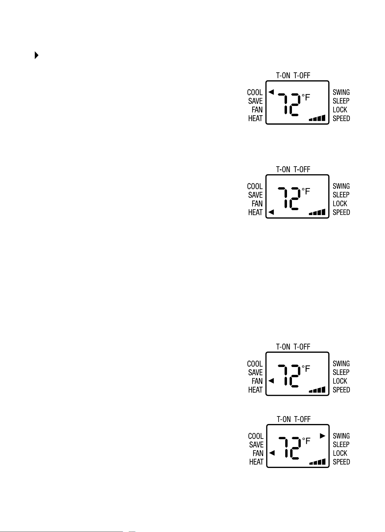
USING THE REMOTE CONTROL
COOL Mode
• PresstheON/OFFbuttontoturntheuniton.
• PresstheMODEbuttontoselectCOOL.Anarrowwillappearnexttothis
icon to indicate that it is selected.
• Setthetemperatureusingthe–/+buttons.
• Toselectfanspeed,presstheFANbuttonuntiltherequiredspeedis
selected(LOW/MED/HIGH/AUTO).
NOTE:InCOOLmodetheunitautomaticallyremovesexcessmoisturefrom
the atmosphere.
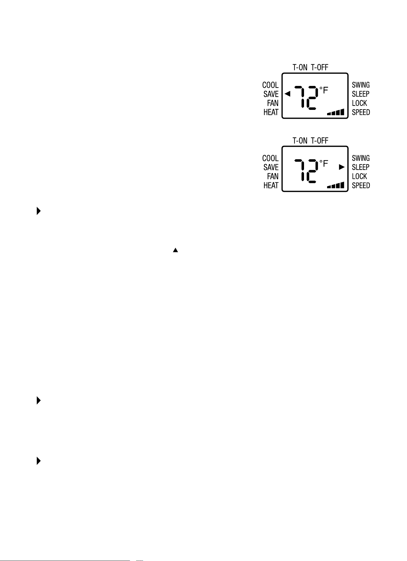
HEAT Mode - Room Heat Pumps
Heatpumpsworkbymovingheatinsteadofcreatingit.Inthesummer,
the cool indoor coil absorbs heat from your room and moves it outdoors,
providing cooling. In the winter, heat pumps reverse this operation. By
lowering the temperature of the outdoor coil below the outdoor temperature,
the heat pump absorbs the heat from outdoors and moves it inside your
house.Thisheattransferringprocessisveryecient.Forexample,at45°F
outdoor temperature, a heat pump can provide 2½ watts of heat for every
watt of electricity it consumes.
Asoutdoortemperaturesdrop,theheatingcapacityandeciencyoftheheat
pumpdeclines.Attemperaturesbelow45°F,itislikelythaticewillformon
the outdoor coil. Heat pump units are designed to operate as a heat pump
above approximately 40°F. Below 40°F, these units switch automatically from
reversecycleheatpumptoauxiliaryelectricheating.Nodefrostisrequired.
There is no minimum operating temperature.
• PresstheON/OFFbuttontoturntheuniton.
• PresstheMODEbuttontoselectHEAT.Anarrowwillappearnexttothis
icon to indicate that it is selected.
• Setthetemperatureusingthe–/+buttons.
• Toselectfanspeed,presstheFANbuttonuntiltherequiredspeedis
selected(LOW/MED/HIGH/AUTO).
FAN Mode
• PresstheON/OFFbuttontoturntheuniton.
• PresstheMODEbuttontoselectFAN.Anarrowwillappearnexttothis
icon to indicate that it is selected.
• Toselectfanspeed,presstheFANbuttonuntilthedesiredspeedis
selected(LOW/MED/HIGH/AUTO).
• Fanspeedisindicatedbytheiconontherightsideofthescreen.
SWING Function
• Presstoautomaticallyswingnsleftandright.
13
ENERGY SAVER Mode
WhiletheunitisrunningpresstheMODEbuttontoselectEnergySaver
(”SAVE”).Whenthesettemperatureisreachedthecompressorwillshuto.
Thefanwillcontinuetorun3minutesafterthecompressorshutso.Theunit
will not run for 10 minutes. After 10 minutes the fan will run for 1 minute and
repeat the cycle. If the temperature changes the compressor will turn on until
the set temperature is reached.
SLEEP Function
The temperature setting will gradually increase to 1ºF above the original
settemperatureforeachoftherst2hours.Theunitwillkeepoperatingat
the same temperature for 6 hours, then switch to standby mode. To set
this function:
• Selecttheoperatingmode(COOL/HEAT).
• PresstheSLEEPbutton;theunitwilloperateintheselectedmode.
SETTING THE TIMER
Thetimercanbeusedtodelaystartuporshutdowntimestoavoidwastingelectricitybyoptimizing
operating periods.
TIMER OFF Function
1. WiththeunitOn,presstheTIMERbutton.The
isdisplayedbelowT-OFFtoindicatethatitisactiveandHwillblink
on the display.
2. Setthetimeyouwanttheunittoswitchousingthe+/–buttonswithin5seconds.
•Youcanselect30minuteintervalsfrom30minutesto24hours.
3. PresstheTIMERbuttonagaintoconrmthesetting.TheTIMERlightonthecontrolpanelwillbeactivated.
•Attheendofthesettime,theapplianceswitchesOautomatically.
•TocanceltheTIMERsetting,presstheTIMERbuttonagainatanypointduringthesettime.
TIMER ON Function
1. Withtheuniton,setoperatingmode,temperatureandfanspeedbeforesettingTimerOnfunction.
2. PressON/OFFbuttontoswitchintoSTANDBY.
3. PresstheTIMERbuttontwice;theT-ONiconwillbeactive.
4. Setthetimeyouwanttheunittoswitchousingthe+/–buttonswithin5seconds.
•Youcanselect30minuteintervalsfrom30minutesto24hours.
5. PresstheTIMERbuttonagaintoconrmthesetting.Thetimericonwillbeactive.
•AttheendofthesettimetheunitswitchesOnautomatically.
•TocanceltheTIMERsetting,presstheTIMERbuttonagainatanypointduringthesettime.
CHILD LOCK FUNCTION
Pressingthe“+”and“–”buttonssimultaneouslyturnsthechildlockfunctionOnorO.Whenchildlockfunctionis
started,theLOCKindicatorontheremotecontrolisOn.Ifyouoperatetheremotecontrol,theremotecontrolwon’tsend
a signal.
TEMPERATURE DISPLAY SWITCHOVER FUNCTION
UnderOstatus,pressthe“–”buttonand“MODE”buttonsimultaneouslytoswitchbetween°Cand°F.
14
CARE AND CLEANING
CAUTION
Cleanairconditioneroccasionallytokeepitlookingandoperatinglikenew.
Be sure to unplug the unit before cleaning to prevent shock or fire hazards.
NOTE: Iftheairlterscreenisblockedbydust,theperformanceoftheunitwillbeaected,theunitwillbelouderthan
normal,andpowerconsumptionwillincrease.Therefore,periodiccleaningoftheairlterscreenisnecessary.
NOTE: The life of your unit may be greatly reduced if you live in a salty air or other corrosive type environment. Under
these conditions, the unit should be removed from its case and completely cleaned at least once a year. At that time any
scratches or blisters on the painted surfaces should be sanded and repainted. Placing an algaecide tablet in the outdoor
side of the unit’s base pan is suggested in humid areas where algae formation is common.
CLEANING THE AIR FILTER
Cleantheairlterscreenthroughouttheoperationalseason.Itisrecommendedthattheairlterscreenbecleanedonce
everytwoweeksusingthemethodbelow:
1. Locate tabs on the bottom of the front grille and gently pull out, lift up, and slide the grille to the left.
2.Locatethehandleonthebottomofthelter.Gentlypullupandouttoremovefromthepanel.
3. Cleantheairlterscreen.Iftheairlterscreenisverydirty,youmayuselukewarmwater(about86ºF/30ºC)tocleanit.
Allow it to completely air dry before returning it to the unit.
NOTE: DO NOTuseboilingwatertocleanthescreen;DO NOT pull or push on the screen with too much force.
4.Installtheairlterscreen.Slidetheairlterbackintoplaceandreinstallthefrontgrille.
NOTE:Iftheairconditionerisoperatedwithoutanairlterscreen,theinterioroftheunitwillbecontaminatedwithdirt
which may cause performance failure or damage to parts.
5. Clean the air conditioner.
•Useasoft,dryclothtowipetheairconditioneroruseavacuumcleanertodothecleaning.
•Iftheairconditionerisverydirty,youmayuseaclothsoakedwithmildhouseholddetergenttodothecleaning.
BEFORE THE SEASON
1. Checktoseeifanythingisblockingtheairinletandfrontgrille.
2. Ensure the bottom of the unit is not corroded or rusty.
3. Ensure the plug is not damaged.
4. Cleantheairlter.
5. Connecttoanappropriateoutletwithsucientpower.Seeproductstickerforinformation.
6. Load fresh batteries into the remote control.
AFTER THE SEASON
1. Pressthepowerbutton.Setthetemperatureto86ºF(30ºC)andletthemachineruninCOOLmodeforhalfofaday.
Makesureanysignsofcondensationontheoutsideoftheunitarewipedowithasoft,dry,cleancloth.
2. Turnotheunit.Unplugtheunitduringnon-operationalseasonstosaveenergyandforsafetyreasons.
3. Cleantheairlterscreenandinstallitbackinplace.
4. Clean the unit.
•Useasoft,dryclothtowipetheairconditioneroruseavacuumcleanertodothecleaning.
•Iftheairconditionerisverydirty,youmayuseaclothsoakedwithmildhouseholddetergenttodothecleaning.
5. Remove the batteries from the remote control.
WARNING
EXCESSIVE WEIGHT HAZARD!
Toreducetheriskofpersonalinjury,weadviseyouhavetheassistanceof2ormore
individuals while moving and installing the air conditioner. Failure to do so can result in
backorotherinjuries.Aroomairconditionercanweighbetween70–240lbs.
15
The following is a list of problems that are sometimes encountered when using a room air conditioner. Possible cause
andsuggestedremediesaregivenforeachproblem.Iftheproblemcannotbexedusingthesuggestedremedies,see
WHEN ASSISTANCE IS REQUIRED section on the next page.
TROUBLESHOOTING
BEFORE CALLING FOR SERVICE, PLEASE REVIEW THE CHART BELOW
ISSUE POSSIBLE CAUSES POSSIBLE SOLUTIONS
UNIT WILL NOT RUN
•No power to unit
•Push reset button on power cord.
•SetFanControltopositionotherthanOFF.
•Makesureplugisrmlyseatedinoutlet.
•Checkforblownfuses,trippedcircuitbreakers.
LITTLE/NO COOLING
LITTLE/NO HEATING
(fan and compressor run)
•Freshair/exhaustdamperopen •SetventtoCLOSED.
•Obstructedindooror
outdoorairow
•Remove obstruction from indoor grille or
outdoor louvers.
•Dirtyairlters •Dirtyairlter.Cleanorreplace,asneeded.
•Unitundersizedforapplication
•Checkwithdealertodeterminepropercapacityunit
for application.
LITTLE/NO COOLING
LITTLE/NO HEATING
(only fan runs)
•Temperature Control not set
properly
•For cooling, turn Temperature Control to
cooler setting.
•For heating, turn Temperature Control to
warmer setting.
NOISY UNIT
•Loose front on
mounting assembly
•Tighten any loose parts.
•Weakbuildingconstruction
•Provide additional support for unit.
•Water hitting fan blade
•Normal in high humidity. Stop noise by removing
drain plug or adding condensate drain cup.
•Unitoversizedforapplication;
compressor cycles on and
ofrequently
•Checkwithdealertodeterminepropercapacityunit
for application.
MOUNTING SUPPORT NOT
INSTALLED
•Storm window frame installed
in window
•Somemodelsrequireremovalofstormwindowframe
before installation.
FROST ON INDOOR COIL
•Dirtyairlter
•Cleanairlterbyvacuumingorwashingwithwater&
mild soap.
•Normal for low outdoor
temperatures
•Turning Temperature Control to warmer setting
reduces occurrence and duration of frost.
FROST ON OUTDOOR COIL
(heat pump)
•Normal for outdoor
temperatures at or below 45°
•Call Consumer Services at 844-472-2473 only if
unitdoesnotheatroomandyouhavechecked
all problems and remedies listed under “Little or
No Heating.”
ODORS IN COOLING
•Mold, mildew, or algae
formation on wet surfaces
•To reduce algae growth, use algaecide tablet in base
pan;removedrainplug;addcondensatedraincup
and hose. Thoroughly clean unit.
ODORS IN HEATING
•Normalforrsttimeheateris
used each season
•Caused by dust accumulation during unused months.
•Odordissipatesquicklywithheateruse.
WARNING
Toreducetheriskofelectricshock,personalinjury,ordeath,turnthefancontroltotheOFF position
andremovetheunitplugfromthewalloutletbeforedoinganyinspectionormaintenancework

16
The design and specifications are subject to change without prior notice for
product improvement. Consult with the sales agency or manufacturer for details.
BEFORE CALLING FOR SERVICE, PLEASE REVIEW THE CHART BELOW
ISSUE POSSIBLE CAUSES
WATER PUDDLES INSIDE
UNIT OR IS COMING
INTO ROOM
•Adjustslopeofunitsoitdrainsdownwardtowardtheexteriorofthehome.
(Seeinstallationinstructions.)
•Makesurethatthereisnodebrisblockingthedrainageareaoftheunit.
•If the air conditioner operates in high humidity for a long time, moisture may be
condensedandappearattheairoutlets(louvers).
WATER DRIPPING OUTSIDE
•Unitisremovingalargequantityofmoisturefromahumidroom.Thisisnormalduring
excessively humid days.
NO REMOTE CONTROL
SIGNAL IS RECEIVED
•When the signal receiver on the air conditioner is exposed to sunlight or strong lights, it
mayfailtoreceivetheremotecontrolsignal.Shadeothesunlightordimthelighting.
•Ensurenothingisblockingthepathbetweentheremotecontrolandthesignalreceiver
on the unit.
•Checkthebatteriesintheremote.
UNIT BLOWS FUSES OR
POPS CIRCUIT BREAKER
•Makesurethereareenoughavailableampsonthecircuitfortheairconditioner.
•Largeunitswhichrunona230Vwillrequireadedicated20or30ampcircuit.
•Adedicatedpoweroutletisrequiredforallairconditioners.
ANY QUESTIONS?
Mostquestionscanbeansweredbyfollowingthe
troubleshooting tips included in this manual. If you have
other matters that cannot be resolved locally or you
need additional information regarding other cooling and
heatingproductsoeredbyPerfectAire,pleasecall:
CONSUMERSERVICES
Tel:844-4PA-AIRE(844-472-2473)
Website: www.perfectaire.us
WHEN ASSISTANCE IS REQUIRED
Help us give you prompt service by providing:
• Anaccuratedescriptionofproblem
• Completemodel,serial,andmanufacturingnumbers
fromproductsticker
• Proofofpurchase(salesreceipt)uponrequest
Repairbyunauthorizedservicerthatresultsin
subsequentfailureofunitvoidswarranty.Warranty
detailsarecontainedinwarrantycerticateenclosed
with unit. Keep accurate records of service calls,
including what was done, servicer's name, and date
of service.

Distributed by:
Perfect Aire, LLC
5401 Dansher Rd.
Countryside, IL 60525
844-4PA-AIRE | 844-472-2473
www.perfectaire.us
WINDOW
AIR CONDITIONER
FOR MODEL:
2PAHP18002
WITH HEAT PUMP
Before using your air conditioner, please
read this manual carefully and keep it for
future reference, along with your receipt.
Specification and performance data is subject to change without notice.
Printed in China
PA/User_2PAHP18002/11212017
USER MANUAL