Loading ...
Loading ...
Loading ...
6 | TEMPRA & TEMPRA PLUS WWW.STIEBEL-ELTRON-USA.COM
INSTALLATION
WATER CONNECTIONS
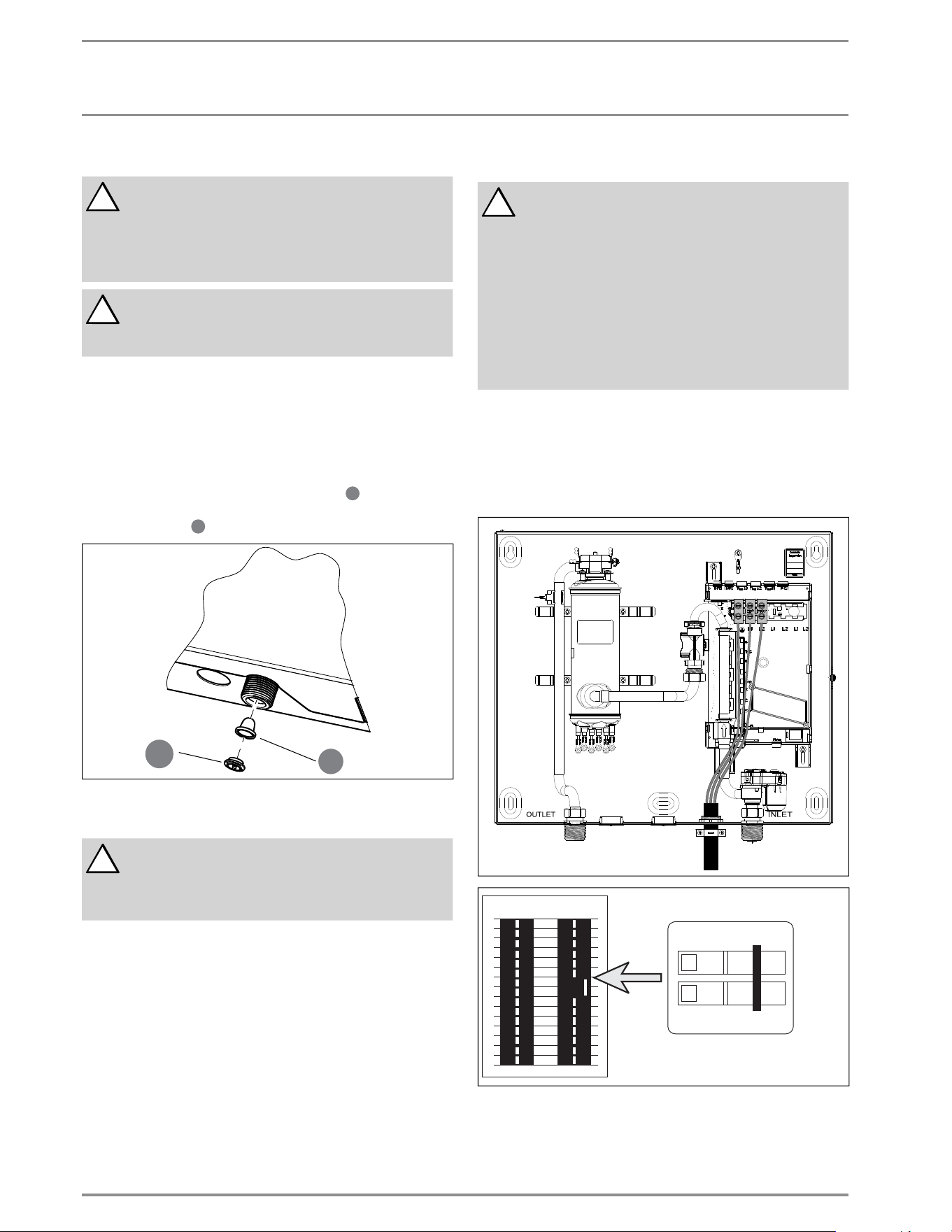
7. Water connections
!
NOTICE: Excessive heat from soldering on copper pipes
near the tempra may cause damage.
The cold water connection to the unit must be discon-
nected periodically in order to clean the fi lter screen.
It is required to use water connections that are easily
detachable such as braided steel fl ex connectors.
!
NOTICE: Hard water or water with a high mineral
count may damage the unit. Damage to the unit caused
by scale or a high mineral count is not covered under
the warranty.
1. All plumbing work must comply with national and applicable
state and local plumbing codes.
2. A pressure reducing valve must be installed if the cold water
supply pressure exceeds 150 PSI (10 bar).
3. Make certain that the cold water supply line has been fl ushed
to remove any scale and dirt.
4. The Tempra unit has a built in fi lter screen
1
2
3
4
5
6
7
8
10
11
12
13
14
15
16
17
18
19
20
21
22
23
24
9
that should be
cleaned from time to time. Clean screen and put the screen
and the washer
1
2
3
4
5
6
7
8
10
11
12
13
14
15
16
17
18
19
20
21
22
23
24
9
back into their original position.
1
2
3
4
5
6
7
8
10
11
12
13
14
15
16
17
18
19
20
21
22
23
24
9
26_02_02_0877
1
2
3
4
5
6
7
8
10
11
12
13
14
15
16
17
18
19
20
21
22
23
24
9
5. The cold water connection (inlet) is on the right side of the
unit, and the hot water connection (outlet) is on the left side
of the unit.
!
NOTICE: Tankless water heaters such as the TEMPRA
are not required to be equipped with a pressure and
temperature relief valve (P&T). If the local inspector
will not pass the installation without a P&T, it should
be installed on the hot water outlet side of the unit.
6. The Tempra on the hot side is designed for connection to
copper
tubing, PEX tubing or a braided stainless steel hose with a
3/4" NPT female tapered thread.
The plumbing on the cold water inlet side needs to be such
that
it can easily be removed to allow access to the inlet fi lter
screen.
The easiest way to achieve this is to us a stainless steel
braided hose connector.
If soldering near the unit is necessary, please direct the
fl ame away from the housing of the unit in order to avoid
damage.
7. When all plumbing work is completed, check for leaks and
take corrective action before proceeding.
8. Electrical connection
!
WARNING: Before beginning any work on the electric
installation, be sure that main breaker panel switch-
es are "off" to avoid any danger of electric shock. All
mounting and plumbing must be completed before
proceeding with electrical hook-up. Where required
by local, state or national electrical codes the circuits
should be equipped with a "ground fault interrupter".
The unit must be properly grounded in accordance
with state and local codes, or in absence of such
codes, in accordance with national electric code or the
Canadian electric code. Failure to electrically ground
the product could result in serious personal injury or
death.
The Tempra should be connected to properly grounded dedicated
branch circuits of proper voltage rating. Ground must be brought
to the "Ground" at the circuit breaker panel.
8.1 Circuit Layout
8.1.1 Tempra 12 B / Tempra 12 Plus
OFF
ON
OFF
ON
26_02_02_0568
CKT 1
Tempra 12 B/Plus: These units can be connected to a single circuit. Use
a supply cable protected by a double pole breaker.
Loading ...
Loading ...
Loading ...