OPERATION AND INSTALLATION
TANKLESS ELECTRIC WATER HEATERS
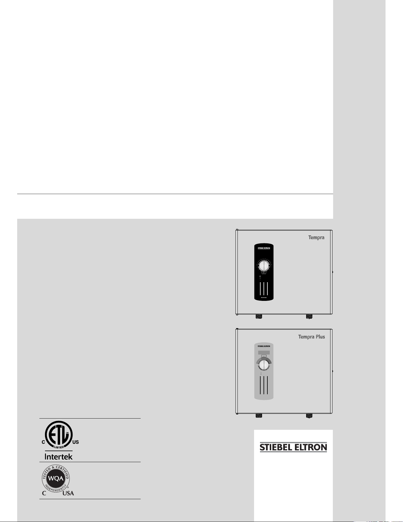
»TEMPRA® 12 B
»TEMPRA® 15 B
»TEMPRA® 20 B
»TEMPRA® 24 B
»TEMPRA® 29 B
»TEMPRA® 36 B
»TEMPRA® 12 PLUS
»TEMPRA® 15 PLUS
»TEMPRA® 20 PLUS
»TEMPRA® 24 PLUS
»TEMPRA® 29 PLUS
»TEMPRA® 36 PLUS
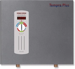
Blinking: maximum power,
less than set point temp.
Steady: unit operating
Off: unit off
H
a
n
d
W
a
s
h
i
n
g
|
R
e
s
i
d
e
n
t
i
a
l
U
s
e
|
C
o
m
m
e
r
c
i
a
l
O
n
l
y
S
C
A
L
D
I
N
G
D
A
N
G
E
R
Tankless Electric Water Heater
with electronic temperature control
°F °C
Made in Germany
Power
Tankless Electric Water Heater
with electronic temperature control
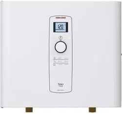
On: unit operating
Off: unit off
S
C
A
L
D
I
N
G
D
A
N
G
E
R
H
a
n
d
W
a
s
h
i
n
g
R
e
s
i
d
e
n
t
i
a
l
U
s
e
C
o
m
m
e
r
c
i
a
l
O
n
l
y
The TEMPRA series is
tested and certifi ed by WQA
against NSF/ANSI 372 for
lead free compliance.
2 | TEMPRA & TEMPRA PLUS WWW.STIEBEL-ELTRON-USA.COM
CONTENTS | OPERATION
OPERATION
1. General Information
Read this entire manual. Failure to follow all the guides, instruc-
tions and rules could cause personal injury or property damage.
Improper installation, adjustment, alteration, service and use of
this unit can result in serious injury.
This unit must be installed by a licensed electrician and plumber.
The installation must comply with all national, state and local
plumbing and electric codes. Proper installation is the responsi-
bility of the installer. Failure to comply with the installation and
operating instructions or improper use voids the warranty.
Save these instructions for future reference. Installer should leave
these instructions with the consumer.
If you have any questions regarding the installation, use or opera-
tion of this water heater, or if you need any additional installation
manuals, please call our technical service line at 800-582-8423
(USA and Canada only). If you are calling from outside the USA or
Canada, please call USA 413-247-3380 and we will refer you to a
qualifi ed Stiebel Eltron service representative in your area.
!
This is the safety alert symbol. It is used to alert you to
potential personal injury hazard. Obey all safety mes-
sages that follow this symbol to avoid possible injury
or death.
2. Safety
Observe the following safety information and regulations.
Operate the appliance only when fully installed and with all safety
equipment fi tted.
2.1 Intended use
The appliance is intended for heating domestic hot water and can
supply several draw-off points.
Any other use beyond that described shall be deemed inappro-
priate.
Observation of these instructions is also part of the correct use
of this appliance.
2.2 General Information
Read this entire manual. Failure to follow all the guides, instruc-
tions and rules could cause personal injury or property damage.
Improper installation, adjustment, alteration, service and use of
this appliance can result in serious injury.
This appliance must be installed by a licensed electrician and
plumber. The installation must comply with all national, state and
local plumbing and electric codes. Proper installation is the re-
sponsibility of the installer. Failure to comply with the installation
and operating instructions or improper use voids the warranty.
Save these instructions for future reference. Installer should leave
these instructions with the consumer.
OPERATION
1. General Information _________________________________________2
2. Safety __________________________________________________________2
2.1 Intended use ______________________________________________________ 2
2.2 General Information_____________________________________________ 2
2.3 Safety Precautions _______________________________________________ 3
2.4 Test symbols ______________________________________________________ 3
3. Register your product _______________________________________3
4. General ________________________________________________________3
4.1 General appearance _____________________________________________ 4
4.2 Tempra B units: __________________________________________________ 4
INSTALLATION
5. Installation confi guration ___________________________________5
6. Mounting the unit ____________________________________________5
7. Water connections ___________________________________________6
8. Electrical connection _________________________________________6
8.1 Circuit Layout _____________________________________________________ 6
8.2 Circuit Connection _______________________________________________ 7
8.3 Terminal block ____________________________________________________ 8
9. Initial settings ________________________________________________8
10. Commissioning the water heater ___________________________8
11. Normal maintenance _________________________________________8
12. Troubleshooting ______________________________________________9
13. Technical Data ________________________________________________9
13.1 Tempra B __________________________________________________________ 9
13.2 Tempra Plus ______________________________________________________ 10
13.3 Temperature increase above ambient water temperature
_____________________________________________________________________ 11
13.4 Dimensions _______________________________________________________12
13.5 Wiring Diagrams ________________________________________________ 13
14. Spare parts _________________________________________________ 14
15. Warranty ____________________________________________________ 16
WWW.STIEBEL-ELTRON-USA.COM TEMPRA & TEMPRA PLUS | 3
ENGLISH
OPERATION
REGISTER YOUR PRODUCT
If you have any questions regarding the installation, use or opera-
tion of this water heater, or if you need any additional installation
manuals, please call our technical service line at (800)-582-8423.
2.3 Safety Precautions
!
DANGER: Injury
Please read and follow these instructions. Failure to
follow these instructions could result in serious per-
sonal injury or death.
!
Damage to the appliance and the environment
The appliance must be installed by a licensed electrician
and plumber. The installation must comply with all na-
tional, state and local plumbing and electric codes.
Service of the appliance must be performed by qualifi ed
service TECHNICIANS.
!
DANGER: Electrocution
Before proceeding with any installation, adjustment.
Alteration, or service of this appliance all circuit
breakers and disconnect switches servicing the appli-
ance must be turned off. Failure to do so could result
in serious personal injury or death.
DANGER: Electrocution
Never remove the appliance‘s cover unless the elec-
tricity servicing the appliance is turned off. Failure to
do so could result in personal injury or death.
DANGER: Electrocution
The appliance must be properly grounded. Failure to
electrically ground the product could result in serious
personal injury or death.
DANGER: Burns
Water temperatures over 125°F (52 °C)can cause
severe burns instantly or death from scalding. A hot
water scalding potential exists if the thermostat on
the appliance is set too high. Households with small
children, disabled or elderly persons may require that
the thermostat be set at 113°F (45 °C) or lower to
prevent possible injury from hot water.
WARNING: Injury
where children or persons with limited physical, sen-
sory or mental capabilities are to be allowed to con-
trol this appliance, ensure that this will only happen
under supervision or after appropriate instructions by
a person responsible for their safety. Children should
be supervised to ensure that they never play with the
appliance.
2.4 Test symbols
See the type label on the appliance.
3. Register your product
You must register this product within 90 days of pur-
chase on our web site in order to activate the standard
warranty or to be eligible for the extended warranty.
Go to our web site at
www.stiebel-eltron-usa.com and click on register
your product.
Before beginning the registration process, we suggest that
you gather the necessary information which will be as
follows:
Type, Example: Tempra 24 Plus (from the label that is on the
unit)
Number listed after “Nr.”
Place of Purchase
Purchase Date
First & Last Name
Email address
Physical Address
Phone Number
Installation Date
IF YOU HAVE ANY QUESTIONS CONCERNING THE REGISTRA-
TION PROCESS OR WARRANTY OPTIONS, PLEASE CONTACT
STIEBEL ELTRON USA DIRECTLY AT (800)-582-8423.
4. General
!
DANGER: Burns
Water temperatures over 125°F (52 °C) can cause
severe burns instantly or death from scalding. A hot
water scalding potential exists if the thermostat on the
appliance is set too high. Households with small
children, disabled or elderly persons may require that
the thermostat be set at 113°F (45 °C) or lower to
prevent possible injury from hot water.
The Tempra B and Tempra Plus units are designed to supply hot
water for a house, apartment or certain commercial applications.
Unlike a conventional storage type water heater the Tempra tank-
less water heater does not store hot water. Instead, water is heated
instantaneously as it fl ows through the unit. The Tempra offers
greater energy effi ciency than storage type water heaters due to
the absence of stand-by losses and reduced hot water pipe runs.
The input of heat into the water is controlled electronically. The
Tempra will deliver any water temperature between 86 °F (30 °C)
and 140 °F (60 °C). Please set the desired temperature using the
knob on the front cover. The Tempra Plus Temperature adjustment
knob can be set to: OFF, 86...140 °F (30...60 °C).
The Tempra B has a °F and a °C scale. The output temperature of
the Tempra Plus is shown in the digital display in °F or °C units.
(°F or °C units can be selected during installation, factory setting:
°F). The maximum temperature is electronically limited to 140 °F
(60 °C).
4 | TEMPRA & TEMPRA PLUS WWW.STIEBEL-ELTRON-USA.COM
For reasons of appliance effi ciency and durability (scaling), the
optimum temperature setting lies between 86 °F (30 °C) and
120 °F (50 °C).
The outlet temperature of the Tempra Plus can be limited (see
"Initial settings").
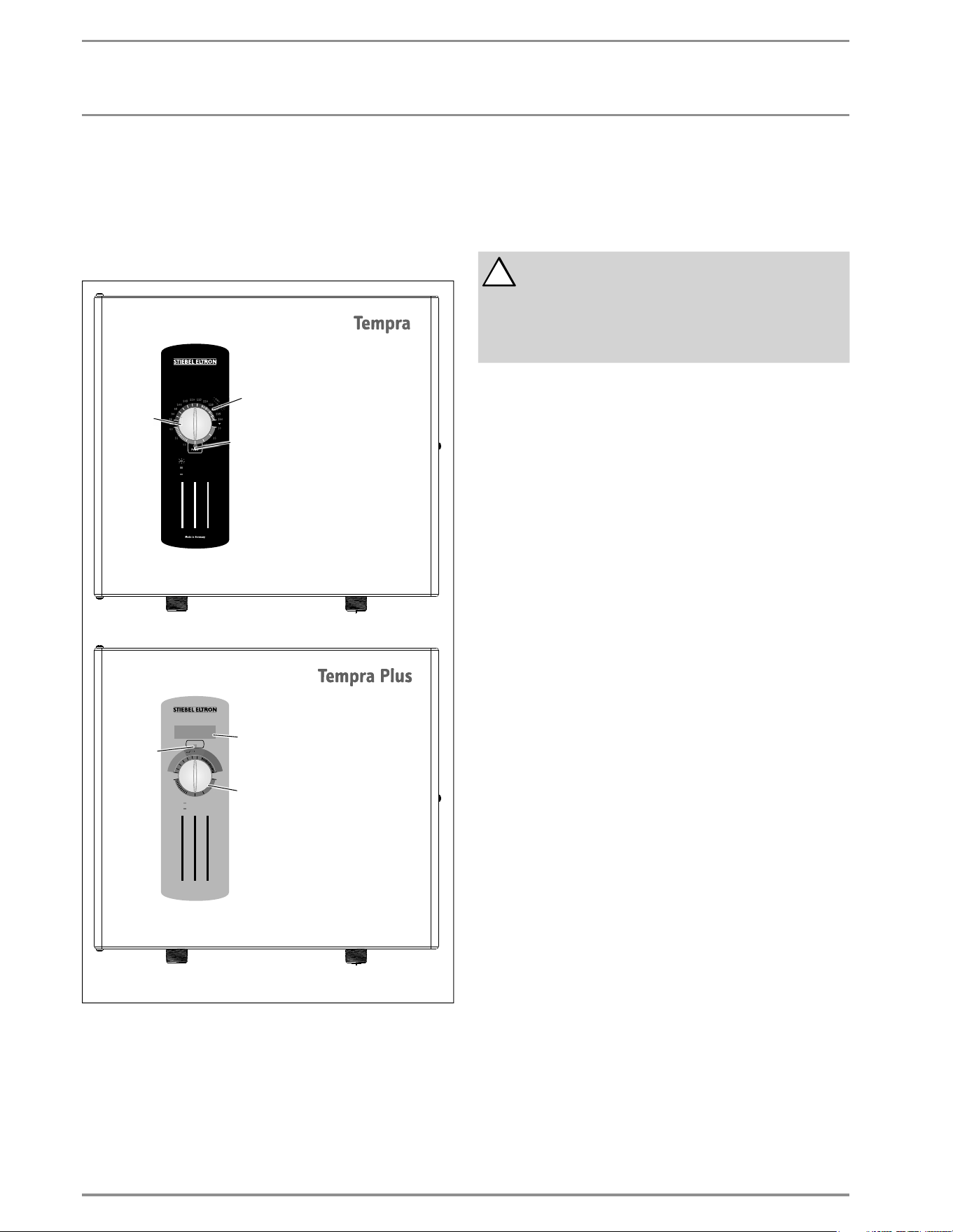
4.1 General appearance
Blinking: maximum power,
less than set point temp.
Steady: unit operating
Off: unit off
H
a
n
d
W
a
s
h
i
n
g
|
R
e
s
i
d
e
n
t
i
a
l
U
s
e
|
C
o
m
m
e
r
c
i
a
l
O
n
l
y
S
C
A
L
D
I
N
G
D
A
N
G
E
R
Tankless Electric Water Heater
with electronic temperature control
°F °C
Made in Germany
Power
Tankless Electric Water Heater
with electronic temperature control
On: unit operating
Off: unit off
S
C
A
L
D
I
N
G
D
A
N
G
E
R
H
a
n
d
W
a
s
h
i
n
g
R
e
s
i
d
e
n
t
i
a
l
U
s
e
C
o
m
m
e
r
c
i
a
l
O
n
l
y
°
F
C
o
m
m
e
r
c
i
i
i
i
i
i
i
i
a
a
a
a
l
l
O
n
l
S
C
A
L
D
I
N
G
D
D
D
D
D
D
D
D
A
N
N
N
N
N
G
E
R
1
3
2
R
e
s
i
d
e
n
3
1
2.1
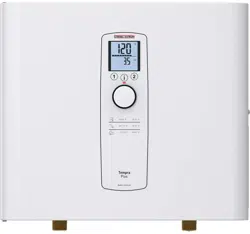
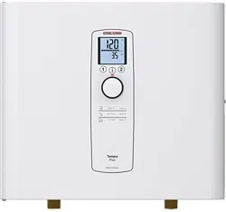
1 Temperature adjustment knob
2 Temperature scale
2.1 Temperature display
3 "Power" light
4.2 Tempra B units:
In case the "Power” LED is fl ashing while the unit operates, the
water fl ow rate exceeds the heating capacity of the unit. Reduce
the hot water fl ow rate in order to let the unit achieve the set
point temperature.
!
In case you have questions regarding the way you
plan to use the Tempra unit, please call our technical
service line at 800-582-8423 (USA and Canada). For
service outside the U.S. and Canada, please call us at
413-247-3380. You can also e-mail us at
info@stiebel-eltron-usa.com or fax us at
413-247-3369.
OPERATION
GENERAL
WWW.STIEBEL-ELTRON-USA.COM TEMPRA & TEMPRA PLUS | 5
INSTALLATION
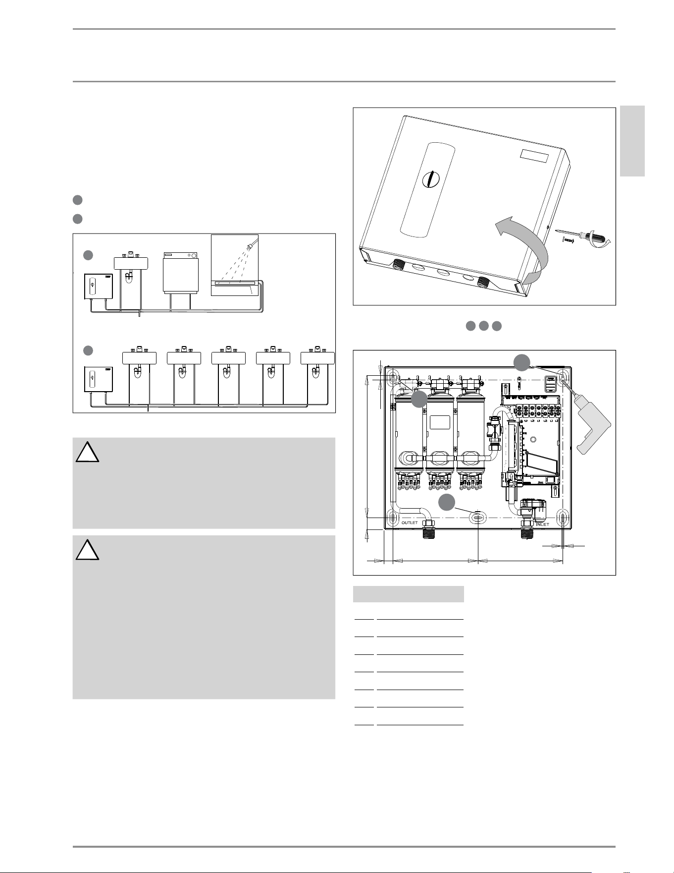
5. Installation confi guration
The Tempra can be used for the following applications.
1
2
3
4
5
6
7
8
10
11
12
13
14
15
16
17
18
19
20
21
22
23
24
9
Typical residential installation
1
2
3
4
5
6
7
8
10
11
12
13
14
15
16
17
18
19
20
21
22
23
24
9
Typical commercial installation
1
2
3
4
5
6
7
8
10
11
12
13
14
15
16
17
18
19
20
21
22
23
24
9
1
2
3
4
5
6
7
8
10
11
12
13
14
15
16
17
18
19
20
21
22
23
24
9
6. Mounting the unit
!
NOTICE: Unit must be installed in a vertical position
with the water fi ttings pointing downward.
WARNING: Do not install unit where it would routinely
be splashed with water. Electric shock may result.
CAUTION: Hot water outlet pipes leaving unit can be
hot to the touch. Insulation must be used for hot water
pipes below 36" due to burn risk to children.
!
NOTICE: This unit should not be installed in a location
where it may be exposed to freezing temperatures
(less than 36 °F). If the unit may be subject to freezing
temperatures all water must be drained from the unit.
Failure to comply with this instruction voids all war-
ranties.
The unit should be located in an area where water
leakage from the unit or connections will not result in
damage to the area adjacent to the unit. If such a loca-
tion cannot be avoided it is recommended that a drain
pan be installed under the unit.
CAUTION: Hot water outlet pipes leaving unit can be
hot to the touch. Insulation must be used for hot water
pipes below 36" due to burn risk to children.
Install Tempra as close as possible to the main hot water draw-
off points.
1. Install Tempra in a frost free area. If frost might occur, re-
move unit before freezing temperatures set in.
2. Leave a minimum of 5" of clearance on all sides for servicing.
3. Remove the cover screw with a #2 Pozi-drive screwdriver and
open the cover .
4. Mount unit securely to wall by putting at least three screws
through mounting holes
1
2
3
4
5
6
7
8
10
11
12
13
14
15
16
17
18
19
20
21
22
23
24
9
1
2
3
4
5
6
7
8
10
11
12
13
14
15
16
17
18
19
20
21
22
23
24
9
1
2
3
4
5
6
7
8
10
11
12
13
14
15
16
17
18
19
20
21
22
23
24
9
. Screws and plastic wall
anchors for mounting on masonry or wood are provided.
DE F
G
A
B
C
1
2
3
4
5
6
7
8
10
11
12
13
14
15
16
17
18
19
20
21
22
23
24
9
1
2
3
4
5
6
7
8
10
11
12
13
14
15
16
17
18
19
20
21
22
23
24
9
1
2
3
4
5
6
7
8
10
11
12
13
14
15
16
17
18
19
20
21
22
23
24
9
Dimensions
A ⅜˝ / 10 mm
B 12½˝ / 318 mm
C 1˝ / 26 mm
D ¾˝ / 19.5 mm
E 7½˝ / 190 mm
F 7½˝ / 190 mm
G
3
/
16
˝ / 5 mm
ENGLISH
INSTALLATION
INSTALLATION CONFIGURATION
6 | TEMPRA & TEMPRA PLUS WWW.STIEBEL-ELTRON-USA.COM
INSTALLATION
WATER CONNECTIONS
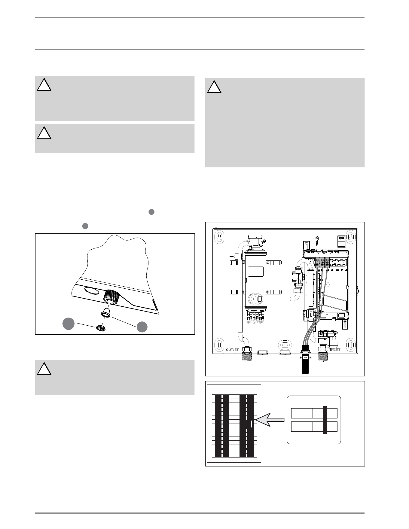
7. Water connections
!
NOTICE: Excessive heat from soldering on copper pipes
near the tempra may cause damage.
The cold water connection to the unit must be discon-
nected periodically in order to clean the fi lter screen.
It is required to use water connections that are easily
detachable such as braided steel fl ex connectors.
!
NOTICE: Hard water or water with a high mineral
count may damage the unit. Damage to the unit caused
by scale or a high mineral count is not covered under
the warranty.
1. All plumbing work must comply with national and applicable
state and local plumbing codes.
2. A pressure reducing valve must be installed if the cold water
supply pressure exceeds 150 PSI (10 bar).
3. Make certain that the cold water supply line has been fl ushed
to remove any scale and dirt.
4. The Tempra unit has a built in fi lter screen
1
2
3
4
5
6
7
8
10
11
12
13
14
15
16
17
18
19
20
21
22
23
24
9
that should be
cleaned from time to time. Clean screen and put the screen
and the washer
1
2
3
4
5
6
7
8
10
11
12
13
14
15
16
17
18
19
20
21
22
23
24
9
back into their original position.
1
2
3
4
5
6
7
8
10
11
12
13
14
15
16
17
18
19
20
21
22
23
24
9
26_02_02_0877
1
2
3
4
5
6
7
8
10
11
12
13
14
15
16
17
18
19
20
21
22
23
24
9
5. The cold water connection (inlet) is on the right side of the
unit, and the hot water connection (outlet) is on the left side
of the unit.
!
NOTICE: Tankless water heaters such as the TEMPRA
are not required to be equipped with a pressure and
temperature relief valve (P&T). If the local inspector
will not pass the installation without a P&T, it should
be installed on the hot water outlet side of the unit.
6. The Tempra on the hot side is designed for connection to
copper
tubing, PEX tubing or a braided stainless steel hose with a
3/4" NPT female tapered thread.
The plumbing on the cold water inlet side needs to be such
that
it can easily be removed to allow access to the inlet fi lter
screen.
The easiest way to achieve this is to us a stainless steel
braided hose connector.
If soldering near the unit is necessary, please direct the
fl ame away from the housing of the unit in order to avoid
damage.
7. When all plumbing work is completed, check for leaks and
take corrective action before proceeding.
8. Electrical connection
!
WARNING: Before beginning any work on the electric
installation, be sure that main breaker panel switch-
es are "off" to avoid any danger of electric shock. All
mounting and plumbing must be completed before
proceeding with electrical hook-up. Where required
by local, state or national electrical codes the circuits
should be equipped with a "ground fault interrupter".
The unit must be properly grounded in accordance
with state and local codes, or in absence of such
codes, in accordance with national electric code or the
Canadian electric code. Failure to electrically ground
the product could result in serious personal injury or
death.
The Tempra should be connected to properly grounded dedicated
branch circuits of proper voltage rating. Ground must be brought
to the "Ground" at the circuit breaker panel.
8.1 Circuit Layout
8.1.1 Tempra 12 B / Tempra 12 Plus
OFF
ON
OFF
ON
26_02_02_0568
CKT 1
Tempra 12 B/Plus: These units can be connected to a single circuit. Use
a supply cable protected by a double pole breaker.
WWW.STIEBEL-ELTRON-USA.COM TEMPRA & TEMPRA PLUS | 7
ENGLISH
INSTALLATION
ELECTRICAL CONNECTION
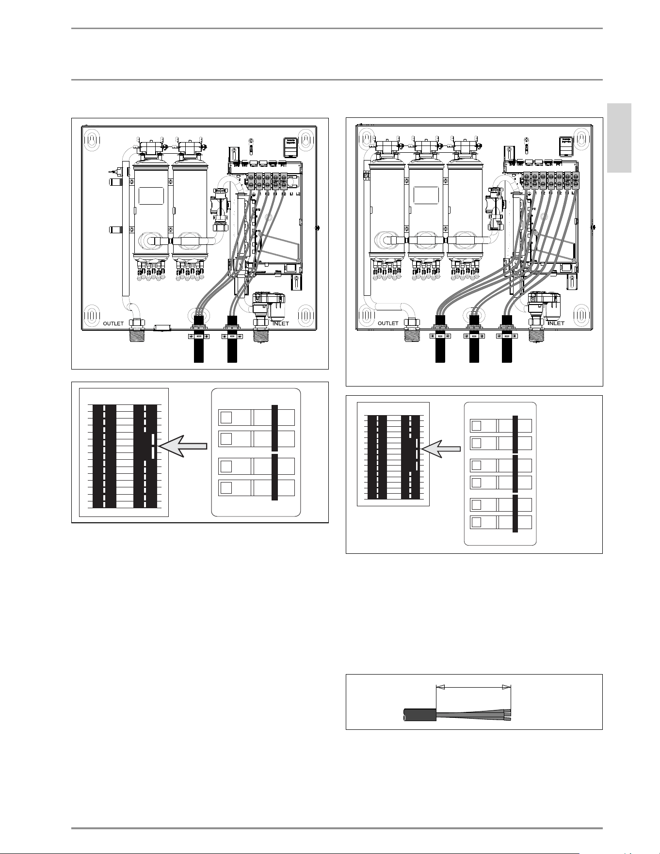
8.1.2 Tempra 15, 20, 24 B / Tempra 15, 20, 24 Plus
OFF
ON
OFF
ON
OFF
ON
OFF
ON
26_02_02_0568
CKT 1
CKT 2
Tempra 15, 20 or 24 B/Plus: These units require two independent
circuits. Use two supply cables protected by two separate double
pole breakers.
8.1.3 Tempra 29, 36 B / Tempra 29, 36 Plus
OFF
ON
OFF
ON
OFF
ON
OFF
ON
OFF
ON
OFF
ON
26_02_02_0568
26_02_02_0881
CKT 1
CKT 2
CKT 3
Tempra 29 or 36 B/Plus These units require three independent circuits.
Use three supply cables protected by three separate double pole
breakers.
8.2 Circuit Connection
Please refer to the technical data table for the correct wire and
circuit breaker size. In all cases, make sure that the unit is properly
grounded.
1. Cut the electrical connection cable to length and strip.
15˝ (380mm)
26_02_02_0893
The wire must be fed through the knock-outs located between
the hot and cold water connections (See 8.1, “Circuit Layout”,
pg. 6). The "live" wires must be connected to the slots on the
terminal block marked L1 and L2. The ground wire must be con-
nected to slot marked with the ground symbol (See 13.5, “Wiring
Diagrams”, pg. 13 ).
8 | TEMPRA & TEMPRA PLUS WWW.STIEBEL-ELTRON-USA.COM
INSTALLATION
INITIAL SETTINGS
8.3 Terminal block
We recommend using stranded wire to connect to the terminal
block. Crimp a ferrule over stranded bare wire to ensure a good
connection.
Consult the chart below for the recommended torque amounts on
the terminal block screws.
Screw Diameter (mm) Torque (N•cm) Torque (lbf•in)
2.8 30-40 2.65-3.54
2.8-3 35-50 3.09-4.42
3-3.2 50-60 4.42-5.31
3.2-3.6 60-80 5.31-7.08
3.6-4.1 90-120 7.96-10.62
4.1-4.7 120-180 10.62-15.93
4.7-5.3 150-200 13.27-17.7
Using the proper torque specifi cations to secure wire to the wiring
block helps to avoid personal loss or property damage.
See 13, “Technical Data”, pg. 9 for information on the proper
wire gauge size.
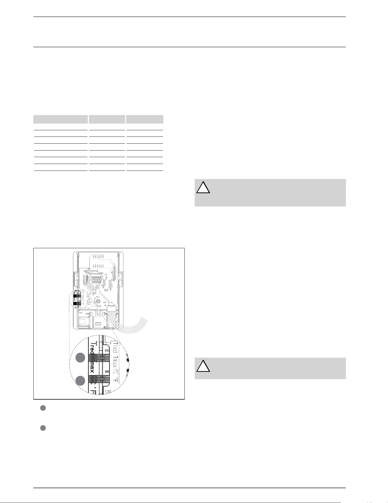
9. Initial settings
Check whether the set value transducer cable is plugged into the
slot T
Soll
A1 (Tempra B) or T
Soll
D (Tempra Plus) on the main PCB.
1
2
3
4
5
6
7
8
10
11
12
13
14
15
16
17
18
19
20
21
22
23
24
9
1
2
3
4
5
6
7
8
10
11
12
13
14
15
16
17
18
19
20
21
22
23
24
9
-
1
2
3
4
5
6
7
8
10
11
12
13
14
15
16
17
18
19
20
21
22
23
24
9
Selection of °F or °C units
- Set jumper on the dial-printed circuit board to °F or °C.
-
1
2
3
4
5
6
7
8
10
11
12
13
14
15
16
17
18
19
20
21
22
23
24
9
Activate anti-scalding protection function
On the Tempra Plus, an anti-scalding protection function can be
activated by two different methods.
1. Limit the outlet temperature to the fi xed temperature of
109°F (43 °C).
- Insert the coding plug into position Tred (reduced
temperature).
2. Select a specifi c outlet temperature
- Switch the appliance 'live'.
- Open the casing so that coding plug T
max
/ T
red
becomes
accessible.
- Set the temperature selector to "OFF". The coding plug must
be set to T
max
(standard delivery).
- Set coding plug to T
red
; the setting mode will be activated and
the fl ashing display shows the current temperature limit.
- Within the next 30 seconds, you can select the required
temperature (display continues to fl ash). The setting mode
will terminate after 30 seconds; the programming unit will
display "OFF" again.
10. Commissioning the water heater
!
WARNING: Open hot water faucet for a few minutes
until water fl ow is continuous and all air is purged
from water pipes. The unit’s cover must be installed
before the circuit breakers are turned on.
1. Close the cover and fi x it using the screw with the lock
washer.
2. Turn on circuit breakers to bring electrical power to the unit.
3. Turn the temperature selector clockwise and anti-clockwise,
to calibrate the set value transducer.
4. Adjust the water temperature to the desired level using the
knob on the front cover of the unit.
5. Turn on hot water and wait twenty seconds until temperature
has stabilized.
6. Check the water temperature with your hand and make sure
that it does not feel too hot. Reduce if necessary.
7. Explain to the user how the unit works and familiarize him
or her with its use.
Advise the user about possible hazards (hot water tempera-
ture up to 140 °F / 60 °C). Hand over these instructions, to be
kept for future reference.
11. Normal maintenance
!
NOTICE: The Tempra does not contain any parts ser-
viceable by the average user. In case of malfunction
please contact a licensed plumber or electrician.
Stiebel Eltron Tempra tankless water heaters are designed for a
very long service life. Actual life expectancy will vary with water
quality and use. The unit itself does not require any regular main-
tenance. However, to ensure consistent water fl ow, it is recom-
mended to periodically remove scale and dirt that may build up
at the aerator of the faucet(s), the fi lter screen in the unit, or in
the shower head.
WWW.STIEBEL-ELTRON-USA.COM TEMPRA & TEMPRA PLUS | 9
ENGLISH
INSTALLATION
TROUBLESHOOTING
12. Troubleshooting
Symptom Possible cause Solution
No hot water – circuit breakers off
– safety thermal cut-out tripped
– not enough flow rate to activate unit
– turn circuit breakers on
– reset safety thermal cut-out
– clean filter screen at unit
– clean faucet aerator or shower head
Not enough hot water – filter screen clogged – clean filter screen at unit
Water not hot enough – water flow rate too high
– voltage too low
– reduce water flow rate until power light on front cover stops blinking
– supply correct voltage to unit
If you are not able to resolve a problem please contact us toll free at 800-582-8423 before removing the unit from the wall.
Stiebel Eltron is happy to provide technical assistance. In most instances, we can resolve the problem over the phone.
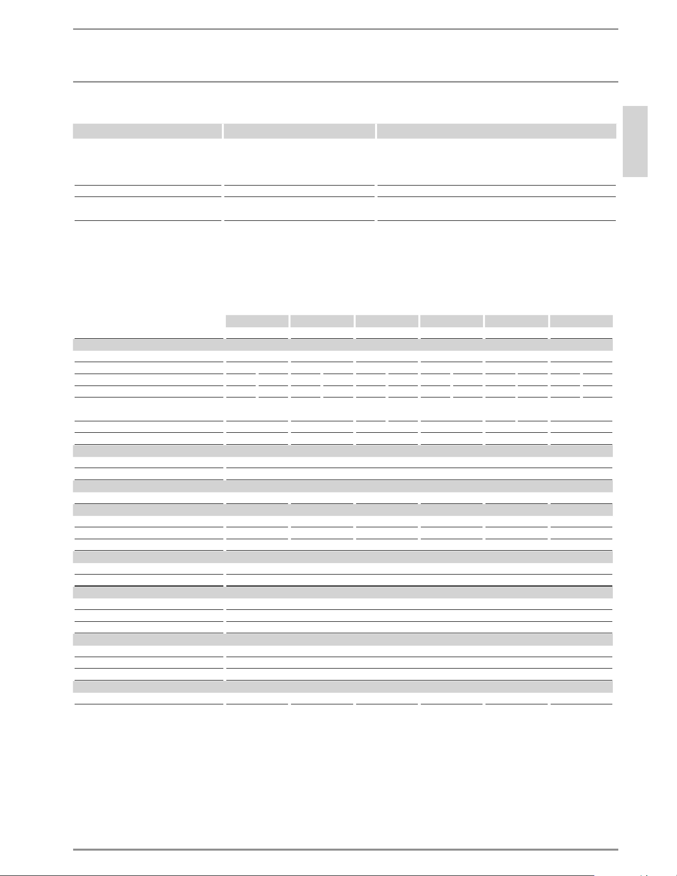
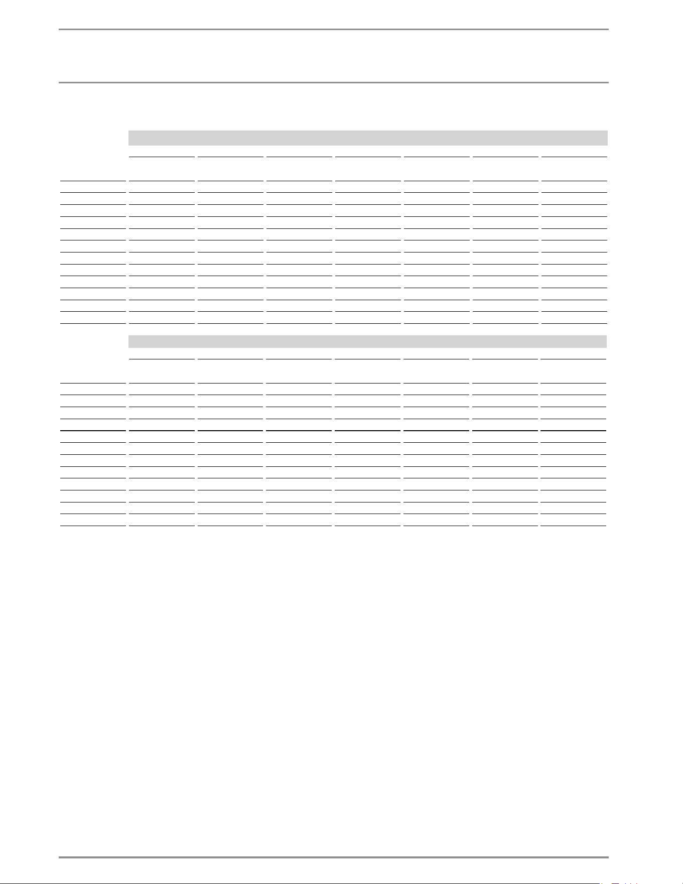
13. Technical Data
13.1 Tempra B
Tempra 12 B Tempra 15 B Tempra 20 B Tempra 24 B
3
Tempra 29 B
3
Tempra 36 B
4
Part number 223420 223421 223422 223424 232885 232886
Electrical details
Phase single 50/60 Hz single
5
50/60 Hz single
5
50/60 Hz single
5
50/60 Hz single
5
50/60 Hz single
5
50/60 Hz
Voltage 240 V 208 V 240 V 208 V 240 V 208 V 240 V 208 V 240 V 208 V 240 V 208 V
Wattage 12 kW 9 kW 14.4 kW 10.8 kW 19.2 kW 14.4 kW 24 kW 18 kW 28.8 kW 21.6 kW 36 kW 27 kW
Max. amp. load 1 x 50 A 1 x 44 A 2 x 30 A 2 x 26 A 2 x 40 A 2 x 35 A 2 x 50 A 2 x 44 A 3 x 40 A 3 x 35 A 3 x 50 A 3 x 44 A
Number & min. recommended size of circuit
breakers
1
(DP) 1 x 50 A 2 x 30 A 2 x 40 A 2 x 35 A 2 x 50 A 3 x 40 A 3 x 35 A 3 x 50 A
Power connection 1/N/GRD 2/GRD 2/GRD 2/GRD 3/GRD 3/GRD
Min. recommended wire size (copper)
2
1 x 6/2 AWG 2 x 10/2 AWG 2 x 8/2 AWG 2 x 6/2 AWG 3 x 8/2 AWG 3 x 6/2 AWG
Connections
Water connection 3/4“ NPT
Max. cold water temperature 108°F / 42°C
Hydraulic data
Rated capacity 0.13 gal / 0.5 l 0.26 gal / 1.0 l 0.26 gal / 1.0 l 0.26 gal / 1.0 l 0.39 gal / 1.5 l 0.39 gal / 1.5 l
Values
ON 1.4 l/min 1.9 l/min 1.9 l/min 1.9 l/min 2.9 l/min 2.9 l/min
ON 0.37 GPM 0.5 GPM 0.5 GPM 0.5 GPM 0.77 GPM 0.77 GPM
Max. permissible inlet temperature 131°F / 55°C
Application limits
Max. permissible pressure 150 PSI / 1.0 MPa
Test pressure 300 PSI / 2.0 MPa
Versions
Temperature display digital
Cap and back panel sheet steel
Colour grey
Dimensions
Height 14.52 in / 369 mm
Width 16.54 in / 420 mm
Depth 4.61 in / 117 mm
Weights
Weight 13.5 lbs / 6.1 kg 16.1 lbs / 7.3 kg 16.1 lbs / 7.3 kg 16.1 lbs / 7.3 kg 19 lbs / 8.6 kg 19 lbs / 8.6 kg
1
This is our recommendation for overcurrent protection sized at 100% of load. Check local codes for compliance if necessary.
2
Copper must be used. Conductors should be sized to maintain a voltage drop of less than 3% under load.
3
Requires a 200 A main service.
4
Requires a 300 A main service.
5
29 B/29 Plus & 36 B/36 Plus may be wired for balanced 3-phase 208 V. 15 B/15 Plus, 20 B/20 Plus, 24 B/24Plus may be wired for unbalanced 3-phase 208 V.
10 | TEMPRA & TEMPRA PLUS WWW.STIEBEL-ELTRON-USA.COM
INSTALLATION
TECHNICAL DATA
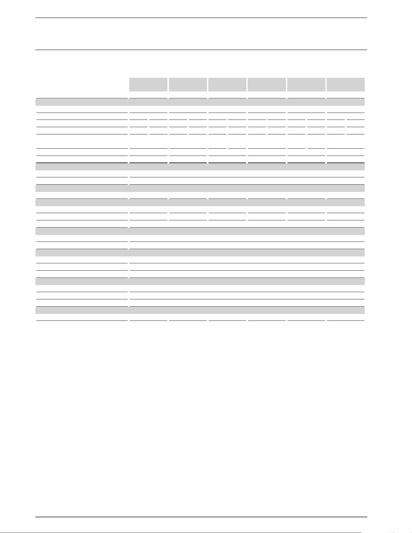
13.2 Tempra Plus
Tempra 12 Plus Tempra 15 Plus Tempra 20
Plus
Tempra 24
Plus
3
Tempra 29
Plus
3
Tempra 36
Plus
4
Part number 224196 224197 224198 224199 223425 223426
Electrical details
Phase single 50/60 Hz single
5
50/60 Hz single
5
50/60 Hz single
5
50/60 Hz single
5
50/60 Hz single
5
50/60 Hz
Voltage 240 V 208 V 240 V 208 V 240 V 208 V 240 V 208 V 240 V 208 V 240 V 208 V
Wattage 12 kW 9 kW 14.4 kW 10.8 kW 19.2 kW 14.4 kW 24 kW 18 kW 28.8 kW 21.6 kW 36 kW 27 kW
Max. amp. load 1 x 50 A 1 x 44 A 2 x 30 A 2 x 26 A 2 x 40 A 2 x 35 A 2 x 50 A 2 x 44 A 3 x 40 A 3 x 35 A 3 x 50 A 3 x 44 A
Number & min. recommended size of circuit
breakers
1
(DP) 1 x 50 A 2 x 30 A 2 x 40 A 2 x 35 A 2 x 50 A 3 x 40 A 3 x 35 A 3 x 50 A
Power connection 1/N/GRD 2/GRD 2/GRD 2/GRD 3/GRD 3/GRD
Min. recommended wire size (copper)
2
1 x 6/2 AWG 2 x 10/2 AWG 2 x 8/2 AWG 2 x 6/2 AWG 3 x 8/2 AWG 3 x 6/2 AWG
Connections
Water connection 3/4“ NPT
Max. cold water temperature 108°F / 42°C
Hydraulic data
Rated capacity 0.13 gal / 0.5 l 0.26 gal / 1.0 l 0.26 gal / 1.0 l 0.26 gal / 1.0 l 0.39 gal / 1.5 l 0.39 gal / 1.5 l
Values
ON 1.4 l/min 1.9 l/min 1.9 l/min 1.9 l/min 2.9 l/min 2.9 l/min
ON 0.37 GPM 0.5 GPM 0.5 GPM 0.5 GPM 0.77 GPM 0.77 GPM
Max. permissible inlet temperature 131°F / 55°C
Application limits
Max. permissible pressure 150 PSI / 1.0 MPa
Test pressure 300 PSI / 2.0 MPa
Versions
Temperature display digital
Cap and back panel sheet steel
Colour grey
Dimensions
Height 14.52 in / 369 mm
Width 16.54 in / 420 mm
Depth 4.61 in / 117 mm
Weights
Weight 13.5 lbs / 6.1 kg 16.1 lbs / 7.3 kg 16.1 lbs / 7.3 kg 16.1 lbs / 7.3 kg 19 lbs / 8.6 kg 19 lbs / 8.6 kg
1
This is our recommendation for overcurrent protection sized at 100% of load. Check local codes for compliance if necessary.
2
Copper must be used. Conductors should be sized to maintain a voltage drop of less than 3% under load.
3
Requires a 200 A main service.
4
Requires a 300 A main service.
5
29 B/29 Plus & 36 B/36 Plus may be wired for balanced 3-phase 208V. 15 B/15 Plus, 20 B/20 Plus, 24 B/24Plus may be wired for unbalanced 3-phase 208V.
WWW.STIEBEL-ELTRON-USA.COM TEMPRA & TEMPRA PLUS | 11
ENGLISH
INSTALLATION
TECHNICAL DATA
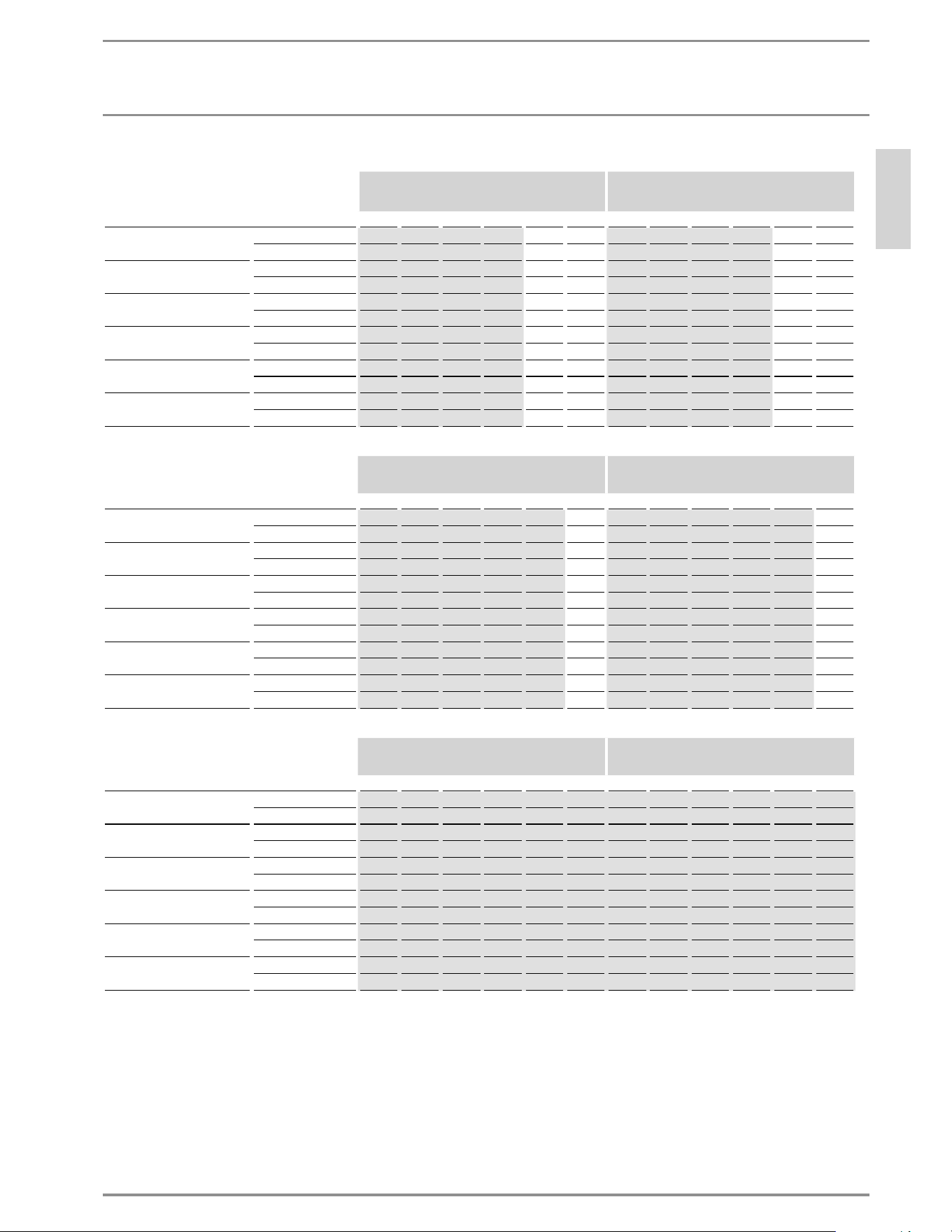
13.3 Temperature increase above ambient water temperature
Hot water fl ow rate [ GPM ] Hot water fl ow rate [ l/m ]
Hot water outlet temperature 105°F Hot water outlet temperature 40°C
Cold water inlet temp. 39°F 59°F 77°F 95°F 113°F 131°F 4°C 15°C 25°C 35°C 45°C 55°C
Tempra 12 B / Tempra 12 Plus
9 kW @ 208 V 0.95 1.36 2.27 6.61 - - 3.58 5.16 8.59 25.00 - -
12 kW @ 220-240 V 1.26 1.82 3.03 6.61 - - 4.77 6.87 11.46 25.00 - -
Tempra 15 B / Tempra 15 Plus
10.8 kW @ 208 V 1.14 1.63 2.72 6.61 - - 4.30 6.19 10.31 25.00 - -
14.4 kW @ 220-240 V 1.51 2.18 3.63 6.61 - - 5.73 8.25 13.75 25.00 - -
Tempra 20 B / Tempra 20 Plus
14.4 kW @ 208 V 1.51 2.18 3.63 6.61 - - 5.73 8.25 13.75 25.00 - -
19.2 kW @ 220-240 V 2.02 2.91 4.84 6.61 - - 7.64 11.00 18.33 25.00 - -
Tempra 24 B / Tempra 24 Plus
18 kW @ 208 V 1.89 2.72 4.54 6.61 - - 7.16 10.31 17.18 25.00 - -
24 kW @ 220-240 V 2.52 3.63 6.05 6.61 - - 9.55 13.75 22.91 25.00 - -
Tempra 29 B / Tempra 29 Plus
21.6 kW @ 208 V 2.27 3.27 5.45 6.61 - - 8.59 12.37 20.62 25.00 - -
28.8 kW @ 220-240 V 3.03 4.36 6.61 6.61 - - 11.46 16.50 25.00 25.00 - -
Tempra 36 B / Tempra 36 Plus
27 kW @ 208 V 2.84 4.09 6.61 6.61 - - 10.74 15.47 25.00 25.00 - -
36 kW @ 220-240 V 3.78 5.45 6.61 6.61 - - 14.32 20.62 25.00 25.00 - -
Hot water fl ow rate [ GPM ] Hot water fl ow rate [ l/m ]
Hot water outlet temperature 113°F Hot water outlet temperature 45°C
Cold water inlet temp. 39°F 59°F 77°F 95°F 113°F 131°F 4°C 15°C 25°C 35°C 45°C 55°C
Tempra 12 B / Tempra 12 Plus
9 kW @ 208 V 0.83 1.14 1.70 3.41 6.61 - 3.14 4.30 6.44 12.89 25.00 -
12 kW @ 220-240 V 1.11 1.51 2.27 4.54 6.61 - 4.19 5.73 8.59 17.18 25.00 -
Tempra 15 B / Tempra 15 Plus
10.8 kW @ 208 V 1.00 1.36 2.04 4.09 6.61 - 3.77 5.16 7.73 15.47 25.00 -
14.4 kW @ 220-240 V 1.33 1.82 2.72 5.45 6.61 - 5.03 6.87 10.31 20.62 25.00 -
Tempra 20 B / Tempra 20 Plus
14.4 kW @ 208 V 1.33 1.82 2.72 5.45 6.61 - 5.03 6.87 10.31 20.62 25.00 -
19.2 kW @ 220-240 V 1.77 2.45 3.63 6.61 6.61 - 6.71 9.16 13.75 25.00 25.00 -
Tempra 24 B / Tempra 24 Plus
18 kW @ 208 V 1.66 2.27 3.41 6.61 6.61 - 6.29 8.59 12.89 25.00 25.00 -
24 kW @ 220-240 V 2.21 3.03 4.54 6.61 6.61 - 8.38 11.46 17.18 25.00 25.00 -
Tempra 29 B / Tempra 29 Plus
21.6 kW @ 208 V 1.99 2.72 4.09 6.61 6.61 - 7.54 10.31 15.47 25.00 25.00 -
28.8 kW @ 220-240 V 2.66 3.63 5.45 6.61 6.61 - 10.06 13.75 20.62 25.00 25.00 -
Tempra 36 B / Tempra 36 Plus
27 kW @ 208 V 2.49 3.41 5.11 6.61 6.61 - 9.43 12.89 19.33 25.00 25.00 -
36 kW @ 220-240 V 3.32 4.54 6.61 6.61 6.61 - 12.57 17.18 25.00 25.00 25.00 -
Hot water fl ow rate [ GPM ] Hot water fl ow rate [ l/m ]
Hot water outlet temperature 140°F Hot water outlet temperature 60°C
Cold water inlet temp. 39°F 59°F 77°F 95°F 113°F 131°F 4°C 15°C 25°C 35°C 45°C 55°C
Tempra 12 B / Tempra 12 Plus
9 kW @ 208 V 0.61 0.76 0.97 1.36 2.27 6.61 2.30 2.86 3.68 5.16 8.59 25.00
12 kW @ 220-240 V 0.81 1.01 1.30 1.82 3.03 6.61 3.07 3.82 4.91 6.87 11.46 25.00
Tempra 15 B / Tempra 15 Plus
10.8 kW @ 208 V 0.73 0.91 1.17 1.63 2.72 6.61 2.76 3.44 4.42 6.19 10.31 25.00
14.4 kW @ 220-240 V 0.97 1.21 1.56 2.18 3.63 6.61 3.68 4.58 5.89 8.25 13.75 25.00
Tempra 20 B / Tempra 20 Plus
14.4 kW @ 208 V 0.97 1.21 1.56 2.18 3.63 6.61 3.68 4.58 5.89 8.25 13.75 25.00
19.2 kW @ 220-240 V 1.30 1.61 2.08 2.91 4.84 6.61 4.91 6.11 7.86 11.00 18.33 25.00
Tempra 24 B / Tempra 24 Plus
18 kW @ 208 V 1.22 1.51 1.95 2.72 4.54 6.61 4.60 5.73 7.36 10.31 17.18 25.00
24 kW @ 220-240 V 1.62 2.02 2.59 3.63 6.05 6.61 6.14 7.64 9.82 13.75 22.91 25.00
Tempra 29 B / Tempra 29 Plus
21.6 kW @ 208 V 1.46 1.82 2.33 3.27 5.45 6.61 5.52 6.87 8.84 12.37 20.62 25.00
28.8 kW @ 220-240 V 1.95 2.42 3.11 4.36 6.61 6.61 7.36 9.16 11.78 16.50 25.00 25.00
Tempra 36 B / Tempra 36 Plus
27 kW @ 208 V 1.82 2.27 2.92 4.09 6.61 6.61 6.90 8.59 11.05 15.47 25.00 25.00
36 kW @ 220-240 V 2.43 3.03 3.89 5.45 6.61 6.61 9.21 11.46 14.73 20.62 25.00 25.00
12 | TEMPRA & TEMPRA PLUS WWW.STIEBEL-ELTRON-USA.COM
INSTALLATION
TECHNICAL DATA
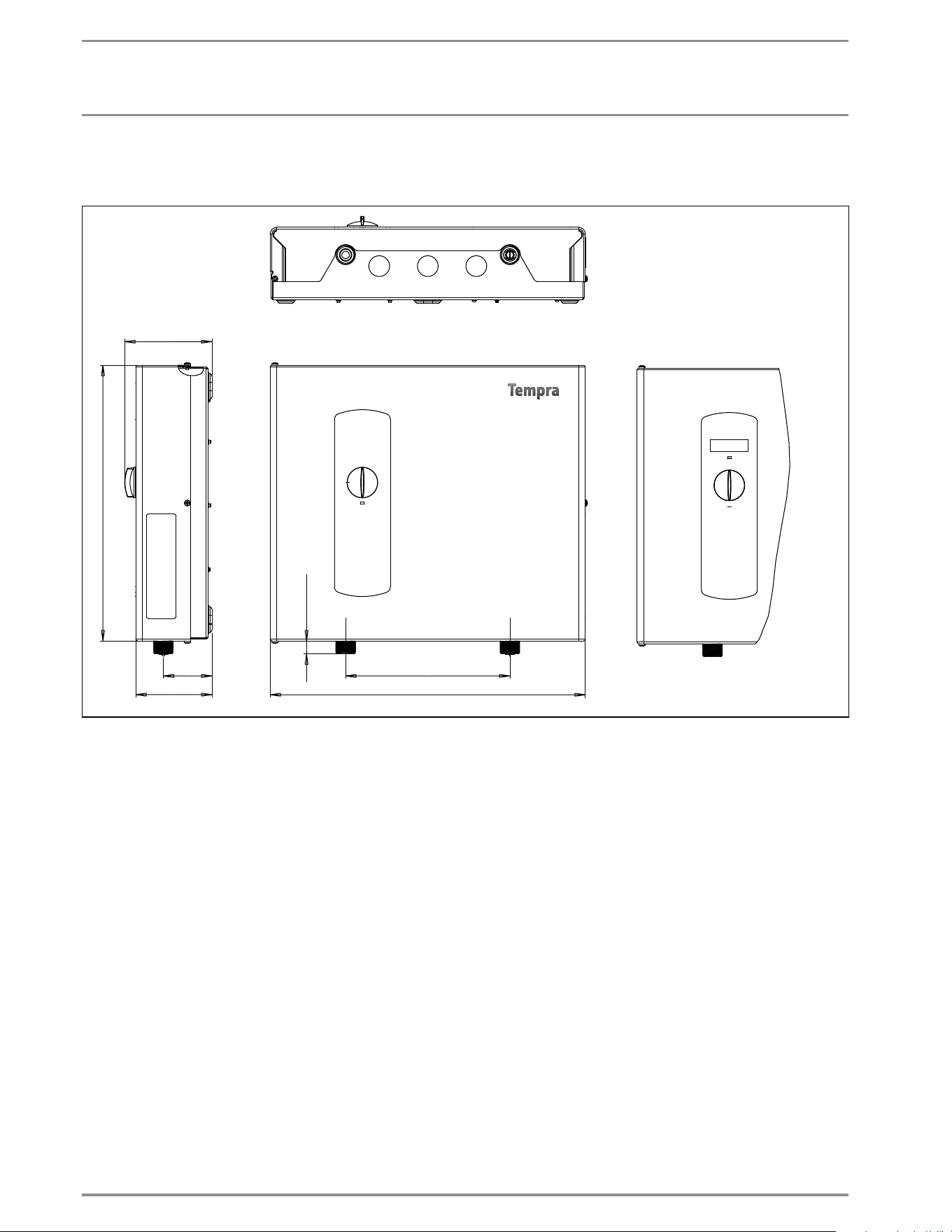
13.4 Dimensions
Tempra B / Tempra Plus
16
5
/
8
˝
(420 mm)
8
5
/
8
˝
(220 mm)
11
/
16
˝
(17.5 mm)
2
9
/
16
˝
(65 mm)
4˝ (102 mm)
14
1
/
2
˝
(369 mm)
4
5
/
8
˝
(117 mm)
Tempra B
Tempra Plus
WWW.STIEBEL-ELTRON-USA.COM TEMPRA & TEMPRA PLUS | 13
ENGLISH
INSTALLATION
TECHNICAL DATA
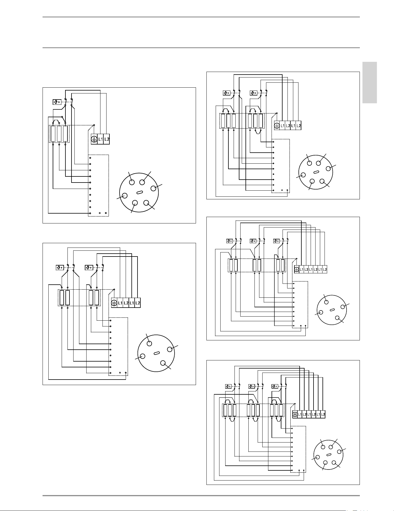
13.5 Wiring Diagrams
13.5.1 Tempra 12 B / Tempra 12 Plus
CKT 1
642
531
6
11/12
5
4
9/10
3
2
7/8
1
13
6
4
2
5
3
1
14 15
D0000039679
13.5.2 Tempra 15, 20 B / Tempra 15,20 Plus
CKT 1
CKT 2
42
51
42
51
6
11/12
5
4
9/10
3
2
7/8
1
13
4
2
5
1
14 15
D0000039678
13.5.3 Tempra 24 B / Tempra 24 Plus
CKT 1
CKT 2
642
531
642
531
6
11/12
5
4
9/10
3
2
7/8
1
13
6
4
2
5
3
1
14 15
D0000039677
13.5.4 Tempra 29 B / Tempra 29 Plus
CKT 1
CKT 2
CKT 3
42
51
42
51
42
51
6
11/12
5
4
9/10
3
2
7/8
1
13
4
2
5
1
14 15
D0000039676
13.5.5 Tempra 36 B / Tempra 36 Plus
CKT 1
CKT 2
CKT 3
642
531
642
531
642
531
6
4
2
5
3
1
6
11/12
5
4
9/10
3
2
7/8
1
13
14 15
D0000039675
14 | TEMPRA & TEMPRA PLUS WWW.STIEBEL-ELTRON-USA.COM
INSTALLATION
SPARE PARTS
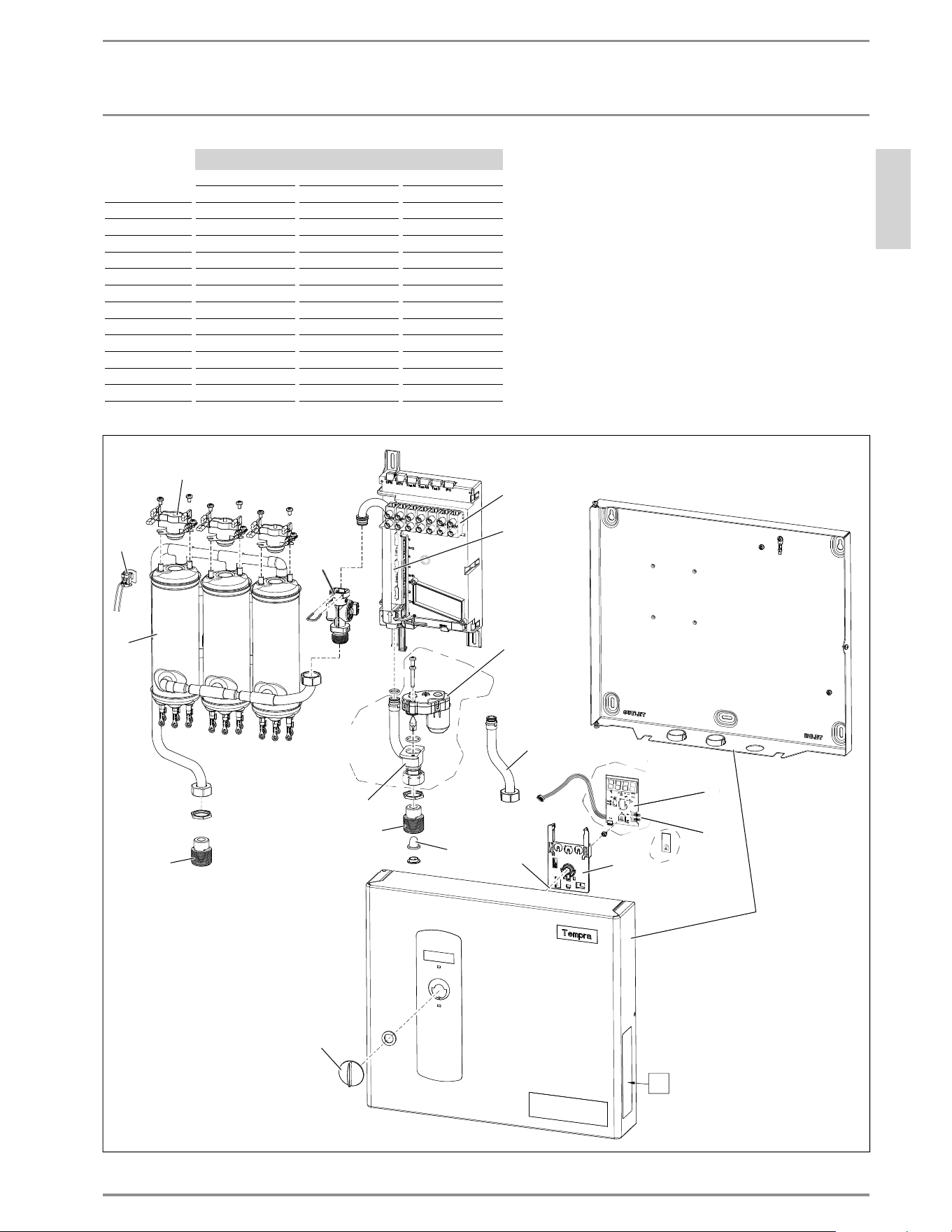
14. Spare parts
Spare part No.
1 2 3 4 5 6 7
Housing
Temp. control knob Wiring block Heating system Safety thermal
cut out
Electronic control
device
Flow sensor
Tempra 12 B 286356 254307 279998 286360 286369 286366 286461
Tempra 15 B 286356 254307 279997 286361 286369 286844 286461
Tempra 20 B 286356 254307 279997 286362 286369 286844 286461
Tempra 24 B 286356 254307 279997 286364 286369 286367 286461
Tempra 29 B 286356 254307 279996 286373 286369 296888 286461
Tempra 36 B 286356 254307 279996 286374 286369 296889 286461
Tempra 12 Plus 286370 254307 279998 286360 286369 286375 286461
Tempra 15 Plus 286370 254307 279997 286361 286369 286845 286461
Tempra 20 Plus 286370 254307 279997 286362 286369 286845 286461
Tempra 24 Plus 286370 254307 279997 286364 286369 286376 286461
Tempra 29 Plus 286370 254307 279996 286373 286369 286378 286461
Tempra 36 Plus 286370 254307 279996 286374 286369 286379 286461
Spare part No.
8 9 10 11 12 13 14
Plumbing con-
nection 3/4"
Advanced Flow
Control
Electronic
temp. control
Jumpers Temperature
sensor
Filter screen Set point case
Tempra 12 B 278698 --- 286359 --- 280677 056755 280730
Tempra 15 B 278698 --- 286359 --- 280677 056755 280730
Tempra 20 B 278698 --- 286359 --- 280677 056755 280730
Tempra 24 B 278698 --- 286359 --- 280677 056755 280730
Tempra 29 B 278698 --- 286359 --- 280677 056755 280730
Tempra 36 B 278698 --- 286359 --- 280677 056755 280730
Tempra 12 Plus 278698 220502 286372 283455 280677 056755 280730
Tempra 15 Plus 278698 220502 286372 283455 280677 056755 280730
Tempra 20 Plus 278698 220502 286372 283455 280677 056755 280730
Tempra 24 Plus 278698 220502 286372 283455 280677 056755 280730
Tempra 29 Plus 278698 220502 286372 283455 280677 056755 280730
Tempra 36 Plus 278698 220502 286372 283455 280677 056755 280730
WWW.STIEBEL-ELTRON-USA.COM TEMPRA & TEMPRA PLUS | 15
ENGLISH
INSTALLATION
SPARE PARTS
Spare part No.
15 16 17
Inlet pipe elbow Valve assembly Axis connection
Tempra 12 B 278695 --- 254312
Tempra 15 B 278695 --- 254312
Tempra 20 B 278695 --- 254312
Tempra 24 B 278695 --- 254312
Tempra 29 B 278695 --- 254312
Tempra 36 B 278695 --- 254312
Tempra 12 Plus --- 280622 254312
Tempra 15 Plus --- 280622 254312
Tempra 20 Plus --- 280622 254312
Tempra 24 Plus --- 280622 254312
Tempra 29 Plus --- 280622 254312
Tempra 36 Plus --- 280622 254312
Tempra B
i
Tempra
Plus
Tempra B
Tempra
Plus
5
12
7
9
15
13
2
3
6
10
11
4
Tempra B
Tempra
P
l
us
1
0
1
1
1
16
14
17
8
26_02_02_0977
8
16 | TEMPRA & TEMPRA PLUS WWW.STIEBEL-ELTRON-USA.COM
WARRANTY | ENVIRONMENT AND RECYCLING
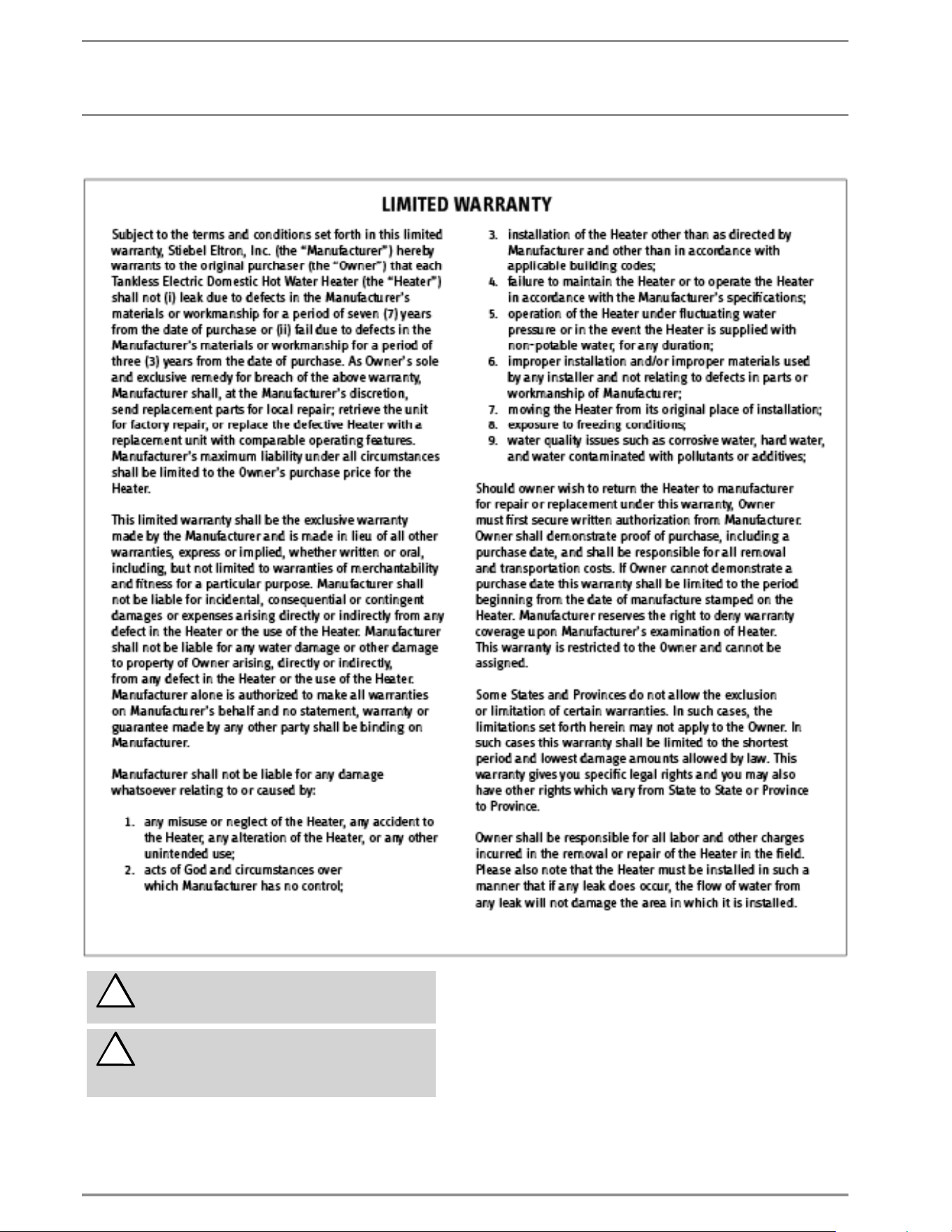
This Warranty is valid for U.S.A. & Canada only. Warranties
may vary by country. Please consult your local Stiebel Eltron
Representative for the Warranty for your country.
!
The installation, electrical connection and first operati-
on of this appliance should be carried out by a qualified
installer.
!
The company does not accept liability for failure of any
goods supplied which have not been installed and ope-
rated in accordance with the manufacturer‘s
instructions.
Environment and recycling
Please help us to protect the environment by disposing of the
packaging in accordance with the national regulations for waste
p
rocessin
g
.
15. Warranty

Subject to errors and technical changes!
STIEBEL ELTRON, Inc.
17 West Street | West Hatfield MA 01088
Tel. 413-247-3380 | Fax 413-247-3369
www.stiebel-eltron-usa.com
A 279626-39663-9167
4<AMHCMN=hjgcgj>
Subject to errors and technical changes! | Salvo error o modifi cación técnica! |
Sous réserve d‘erreurs et de modifi cations techniques!