
September 2006 Rev. 2, 5/20
©2006-2020 Fluke Corporation. All rights reserved.
All product names are trademarks of their respective companies.
Specifications are subject to change without notice.
110/113/114/115/116/117
True-rms Multimeter
Calibration Information
1.888.610.7664 sales@GlobalTestSupply.com
Fluke-Direct.com

LIMITED WARRANTY AND LIMITATION OF LIABILITY
Each Fluke product is warranted to be free from defects in material and workmanship under normal use and service. The
warranty period is three years and begins on the date of shipment. Parts, product repairs, and services are warranted for
90 days. This warranty extends only to the original buyer or end-user customer of a Fluke authorized reseller, and does not
apply to fuses, disposable batteries, or to any product which, in Fluke's opinion, has been misused, altered, neglected,
contaminated, or damaged by accident or abnormal conditions of operation or handling. Fluke warrants that software will
operate substantially in accordance with its functional specifications for 90 days and that it has been properly recorded on
non-defective media. Fluke does not warrant that software will be error free or operate without interruption.
Fluke authorized resellers shall extend this warranty on new and unused products to end-user customers only but have no
authority to extend a greater or different warranty on behalf of Fluke. Warranty support is available only if product is
purchased through a Fluke authorized sales outlet or Buyer has paid the applicable international price. Fluke reserves the
right to invoice Buyer for importation costs of repair/replacement parts when product purchased in one country is submitted
for repair in another country.
Fluke's warranty obligation is limited, at Fluke's option, to refund of the purchase price, free of charge repair, or
replacement of a defective product which is returned to a Fluke authorized service center within the warranty period.
To obtain warranty service, contact your nearest Fluke authorized service center to obtain return authorization information,
then send the product to that service center, with a description of the difficulty, postage and insurance prepaid (FOB
Destination). Fluke assumes no risk for damage in transit. Following warranty repair, the product will be returned to Buyer,
transportation prepaid (FOB Destination). If Fluke determines that failure was caused by neglect, misuse, contamination,
alteration, accident, or abnormal condition of operation or handling, including overvoltage failures caused by use outside
the product’s specified rating, or normal wear and tear of mechanical components, Fluke will provide an estimate of repair
costs and obtain authorization before commencing the work. Following repair, the product will be returned to the Buyer
transportation prepaid and the Buyer will be billed for the repair and return transportation charges (FOB Shipping Point).
THIS WARRANTY IS BUYER'S SOLE AND EXCLUSIVE REMEDY AND IS IN LIEU OF ALL OTHER WARRANTIES,
EXPRESS OR IMPLIED, INCLUDING BUT NOT LIMITED TO ANY IMPLIED WARRANTY OF MERCHANTABILITY OR
FITNESS FOR A PARTICULAR PURPOSE. FLUKE SHALL NOT BE LIABLE FOR ANY SPECIAL, INDIRECT,
INCIDENTAL OR CONSEQUENTIAL DAMAGES OR LOSSES, INCLUDING LOSS OF DATA, ARISING FROM ANY
CAUSE OR THEORY.
Since some countries or states do not allow limitation of the term of an implied warranty, or exclusion or limitation of
incidental or consequential damages, the limitations and exclusions of this warranty may not apply to every buyer. If any
provision of this Warranty is held invalid or unenforceable by a court or other decision-maker of competent jurisdiction, such
holding will not affect the validity or enforceability of any other provision.
11/99
1.888.610.7664 sales@GlobalTestSupply.com
Fluke-Direct.com

i
Table of Contents
Title Page
Introduction ........................................................................................................... 1
How to Contact Fluke............................................................................................ 1
Safety Information................................................................................................. 1
Specifications........................................................................................................ 1
Maintenance ......................................................................................................... 2
Fuse Test (115, 117) ....................................................................................... 2
Battery and Fuse Replacement ....................................................................... 3
Cleaning........................................................................................................... 4
Features................................................................................................................ 5
Performance Tests................................................................................................ 6
Required Equipment ........................................................................................ 6
Display Test ..................................................................................................... 7
110/114/115/116/117 .................................................................................. 7
113 .............................................................................................................. 7
Backlight Test .................................................................................................. 7
Keypad Test..................................................................................................... 7
110/114/115/116/117 .................................................................................. 7
113 .............................................................................................................. 7
Preparing for the Performance Tests............................................................... 8
Testing Temperature (116 only) ...................................................................... 8
Testing the VoltAlert Function (117 only)......................................................... 12
Calibration Adjustment.......................................................................................... 14
Calibration Adjustment Password.................................................................... 14
Changing the Password .............................................................................. 14
Restoring the Default Password.................................................................. 15
Meter Buttons Used in the Calibration Steps................................................... 16
Calibration Adjustment Procedure ................................................................... 16
Replacement Parts ............................................................................................... 19
1.888.610.7664 sales@GlobalTestSupply.com
Fluke-Direct.com

1
Introduction
XW Warning
To prevent electric shock or personal injury, do not perform the calibration verification tests or
calibration procedures described in this manual unless you are qualified to do so. The
information provided in this document is for the use of qualified personnel only.
This Calibration Information provides the information necessary to adjust and verify the performance of the
Fluke Models 110, 113, 114, 115, 115C, 116, 116C, 117, and 117C True RMS Multimeter (the Meter or
Product). When specific models are noted in this manual, the “C” version is also included. For example, when
the listed model is 115, the instructions are applicable to the 115C as well.
Safety Information
General Safety Information is in the printed Safety Information document that ships with the Product and
at More specific safety information is listed where applicable.
Specifications
For complete Specifications, refer to the 110/113/114/115/117 Users Manual or 116 Users Manual at
1.888.610.7664 sales@GlobalTestSupply.com
Fluke-Direct.com
110/113/114/115/116/117
Calibration Information
2
Maintenance
Maintenance of the Meter consists of battery and fuse replacement, as well as case cleaning.
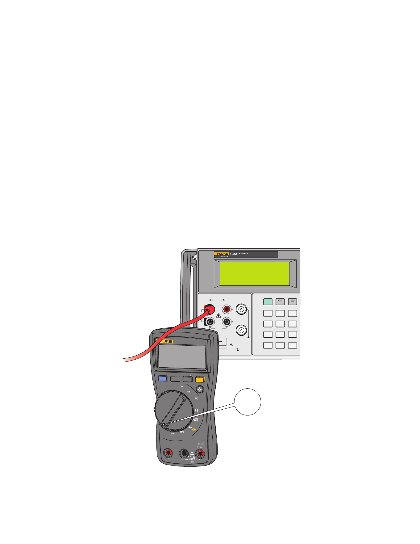
Fuse Test (115, 117)
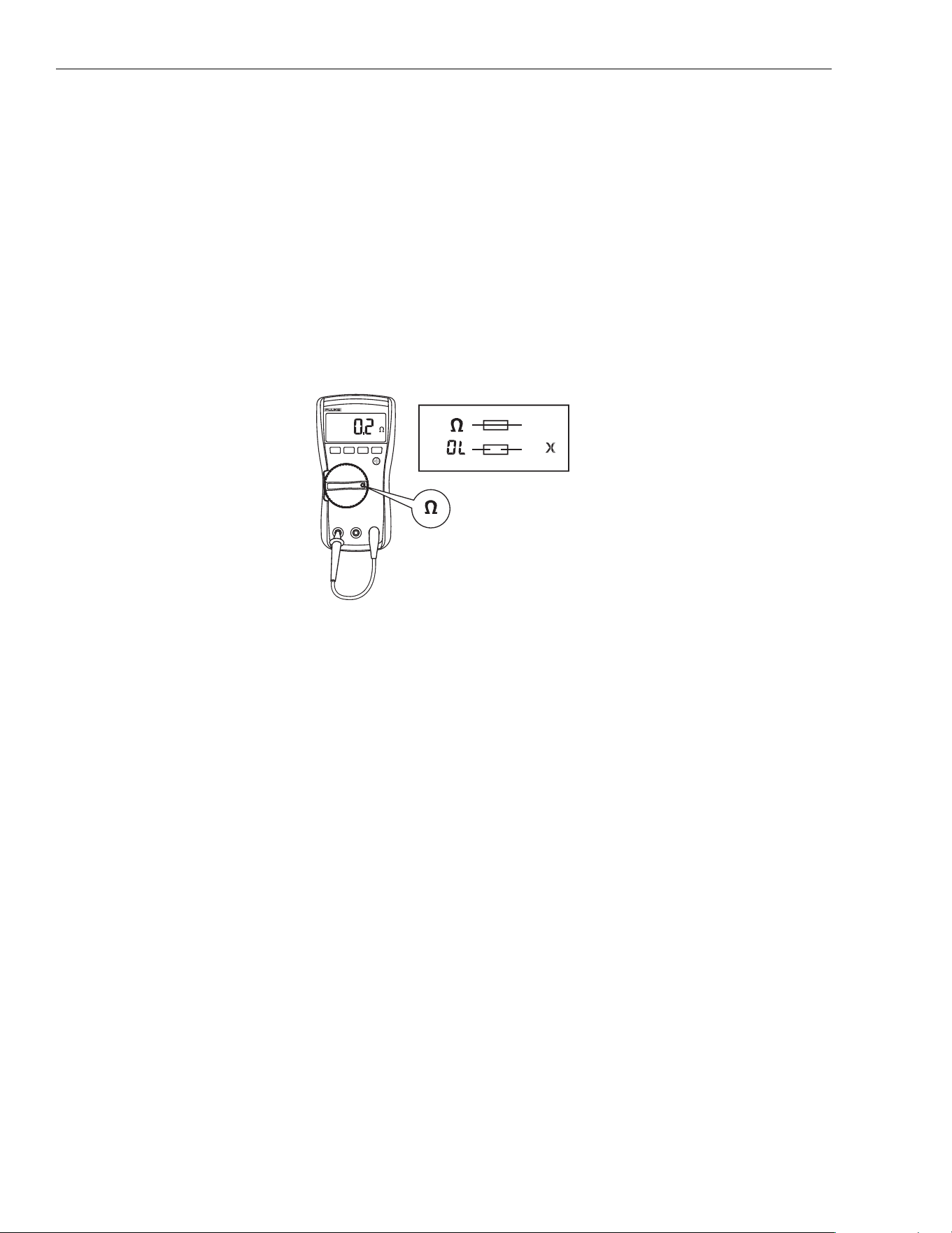
To test the fuse:
1. Set the rotary switch to Ω.
2. Plug a test lead into the v jack and touch the probe to the 10A jack, as shown in Figure 1.
If the display shows a resistance value in the range of that shown in Figure 1, the fuse is good.
If the display reads 0L, replace the fuse and test again.
If the display shows any other value, have the Meter serviced. See How to Contact Fluke earlier in this
document.
Figure 1. Test the Fuse
<.5
OK
OK
X
OK
OK
1.888.610.7664 sales@GlobalTestSupply.com
Fluke-Direct.com
True-rms Multimeter
Maintenance
3
Battery and Fuse Replacement
XW Warning
To prevent shock, injury, or damage to the Meter:
• Remove test leads from the Meter before opening the case or battery door.
• Use ONLY a fuse with the amperage, interrupt voltage, and speed ratings specified.
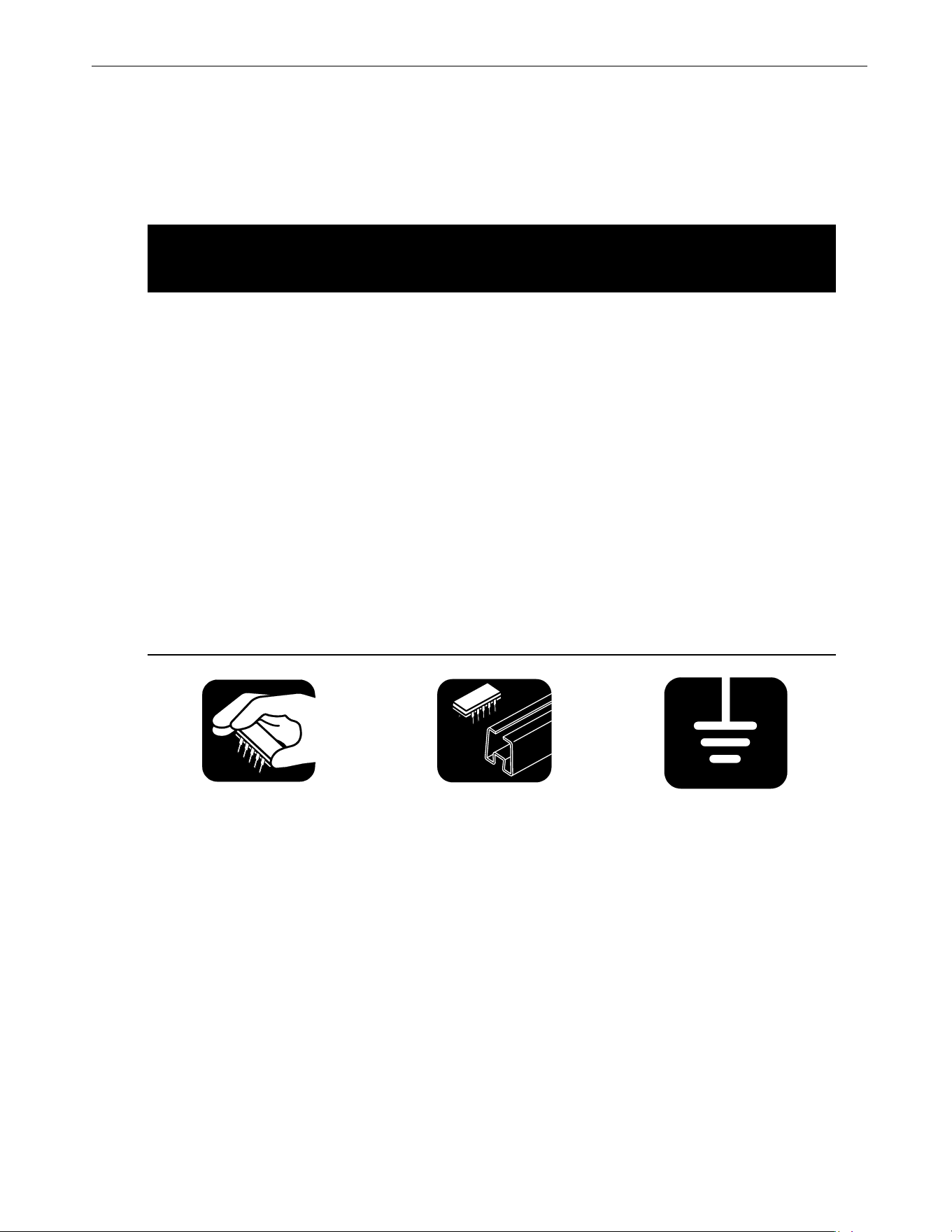
h
Static Awareness
h
X
Semiconductors and integrated circuits can be damaged by electrostatic
discharge during handling. This notice explains how to minimize damage to
these components.
1. Understand the problem.
2. Learn the guidelines for proper handling.
3. Use the proper procedures, packaging, and bench techniques.
Follow these practices to minimize damage to static sensitive parts.
XW Warning
To prevent electric shock or personal injury.
De-energize the product and all active circuits
before opening a product enclosure, touching or
handling any PCBs or components
.
• Minimize handling.
• Handle static-sensitive
parts by non-condu
ctive
edg
es.
• Do not slide static-
sensitive compone
nts
over an
y surface.
• When removing plug-in
assemblies, handle
only
by non-
con
ductive
edges.
•
Never touch open-edge
connectors except at
a
s
tatic-free work station.
• Keep parts in the original
containers until ready for
use.
• Use static shielding
containers for handling a
nd
transpor
t.
• Avoid plastic, vinyl, and
Styrofoam
®
in the work
area
.
• Ha
ndle static-sensitive
parts on
ly at a static-
free work station.
• Put shorting strips
on
the e
dge of th
e
con
nector to
help
prote
ct installed static-
sensitive parts.
• Use anti-static type
solder extraction tools
only.
•
Use grounded-ti
p
soldering irons on
ly.
1.888.610.7664 sales@GlobalTestSupply.com
Fluke-Direct.com

110/113/114/115/116/117
Calibration Information
4
See Figure 2 for disassembly.
Figure 2. Disassembly
To remove the battery door for battery replacement:
1. Remove the test leads from the Meter.
2. Remove the battery door screw.
3. Use the finger recess to lift the door slightly.
4. Lift the door straight up to separate it from the case.
5. The battery fits inside the battery door, which is then inserted into the case, bottom edge first, until it
is fully
se
ated. Do not attempt to install the battery directly into the case.
6. Install and tighten battery door screw.
To open the case for fuse replacement:
1. Remove the test leads from the Meter.
2. Remove the Meter from its holster.
3. Remove two screws from the case bottom.
4. Separate the case bottom from the case top.
5. Remove the fuse from its holder and replace it with an 11 A, 1000 V, FAST fuse having a minimum interrup
t
r
ating of 17 000 A. Use only Fluke PN 803293.
6. To re-assemble the Meter, first attach the case bottom to the case top, then install the two screws.
Finally,
ins
ert the Meter into its holster.
Cleaning
Wipe the case with a damp cloth and mild detergent. Dirt or moisture in the terminals can affect readings.
1.888.610.7664 sales@GlobalTestSupply.com
Fluke-Direct.com

True-rms Multimeter
Features
5
Features
Table 1 is a list of the features for each Meter.
Table 1. Features
Switch
Position
Measurement Function 110 113 114 115 116 117
OFF The Meter is turned off.
x
Automatically selects ac or dc volts based on the sensed
input with a low impedance input.
e
AC voltage from 0.06 V to 600 V.
Frequency from 5 Hz to 100 kHz.
D
DC voltage from 0.001 V to 600 V.
l
AC voltage from 6.0 to 600 mV, dc-coupled.
DC voltage from 0.1 to 600 mV.
Ω
Ohms from 0.1 Ω to 40 MΩ.
Ohms from 0.1 Ω to 60 kΩ.
s
Continuity beeper turns on at <20 Ω and turns off at
>250 Ω.
k CHEK
LoZ low impedance measurement function to
simultaneously test for voltage or continuity.
R Diode Test. Displays OL above 2.0 V.
S Farads from 1 nF to 9999 μF.
j
AC current from 0.1 A to 10 A (>10 to 20 A, 30 seconds
on, 10 minutes off). >10.00 A display flashes. >20 A, OL
is displayed. DC-coupled.
Frequency from 45 Hz to 5 kHz.
I
DC current from 0.001 A to 10 A (>10 A to 20 A,
30 seconds on, 10 minutes off). >10.00 A display
flashes. >20 A, OL is displayed.
$
DC current from 0.1 to 600 μA. AC current from 6.0 to
600 μA. DC-coupled.
y
Temperature from -40 °C to 400 °C (-40 °F to 752 °F)
with K-type thermocouple
w
Non-contact sensing of ac voltage.
Note: All ac functions and Auto-V LoZ are true-rms. AC voltage is ac-coupled. Auto-V LoZ, AC mV and
AC amps are dc-coupled.
1.888.610.7664 sales@GlobalTestSupply.com
Fluke-Direct.com

110/113/114/115/116/117
Calibration Information
6
Performance Tests
XW Warning
To prevent electric shock, do not perform the performance test procedures unless the Meter is
fully assembled.
The following performance tests verify the complete operation of the Meter and check the accuracy of each
Meter function against its specifications. The recommended calibration interval is 12 months. If the Meter fails
any part of the test, calibration adjustment and/or repair is indicated.
In the performance tests, the Meter is referred to as the device under test (DUT).
See Table 1 for a list of the features for each Meter.
Required Equipment
Table 2 is a list of the equipment required to conduct a performance test on the Meter.
Table 2. Equipment Requirements
Equipment
Measurement Function
Range
[1]
5522 Multi-product Calibrator (or equivalent)
DC Volts 10 mV to 600 V
DC Current 600 μA to 10 A
AC Volts 6 mV to 600 V
AC Current 600 μA to 10 A
Resistance 0 to 30 MΩ
Capacitance 9 to 900 μF
Temperature 0 °C to 400 °C
Frequency 2 V, 50 kHz
Fluke 80 AK
K-type Thermocouple Adapter Accessory
Temperature NA
K-type Thermocouple, mini-plug on both ends Temperature NA
Double Banana plug VoltAlert NA
[1] For accuracy specifications, see the Users Manual for the product.
1.888.610.7664 sales@GlobalTestSupply.com
Fluke-Direct.com
True-rms Multimeter
Performance Tests
7
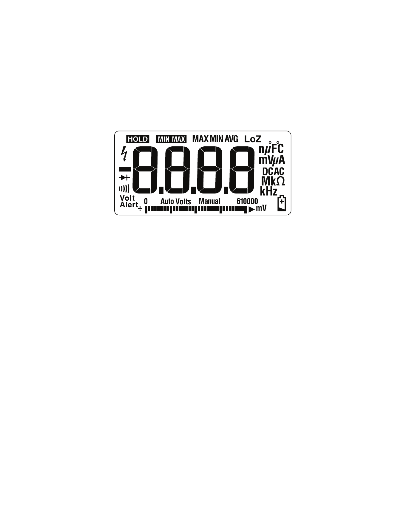
Display Test
110/114/115/116/117
Push K and turn the rotary switch to the e position. Compare the display with the example in Figure 3.
Check all segments for clarity and contrast.
113
Push K and turn the rotary switch to the k CHEK position. Compare the display with the example in
Figure 3. Check all segments for clarity and contrast.
Figure 3. Display Segments
Backlight Test
To test the backlight, press Q and verify that the backlight turns on.
Keypad Test
110/114/115/116/117
To test the keypad:
1. Turn the rotary switch to
.
2. Push each button separate
ly.
Each bu
tton push should cause the Meter to beep and activate a display annunciator.
3. To reset the Meter, turn the rotary switch to Off and then back to the On position.
113
To test the keypad:
1. Turn the Meter to Ω
2.
Push each button separate
ly.
Each bu
tton push should cause the Meter to beep and activate a display annunciator.
3. To reset, turn off the Meter, and then back to any function po
sition.
1.888.610.7664 sales@GlobalTestSupply.com
Fluke-Direct.com

110/113/114/115/116/117
Calibration Information
8
Preparing for the Performance Tests
XW Warning
To prevent possible electric shock or personal injury:
• Do not perform the following procedures unless qualified to do so. Some procedures involv
e
t
he use of high voltages.
• Before handling the test connections and in between tests, make sure the calibrator is
in
s
tandby mode (STBY).
To prepare for the performance test:
1. Make sure that you have the required equipment (see Table 2).
2. Warm up the calibrator as required by its specifications.
3. Allow the temperature of the DUT to stabilize at room temperature: 23 °C ±5 °C (73 °F ±9 °F)
4. Check the fuses and battery and replace them if necessary. See Fuse Test (115, 117) and Battery and Fuse
Replacement.
To verify the accuracy of the DMM functions, do the following:
1. Connect the Calibrator to the VΩ and COM input terminals on the Meter.
2. Turn the rotary switch to the function listed in each step of Table 3 (110, 114, 115, 116, 117) or
Table 4 (113).
3. Apply the input level for each step listed in Table 3 (110, 114, 115, 116, 117) or Table 4 (113).
4. Compare the reading on the Meter display with the Display Reading in Table 3 (110, 114, 115, 116, 117) or
Table 4 (113).
If the display reading falls outside of the range shown, the Meter requires calibration adjustment or repair.
Testing Temperature (116 only)
Connect the K-type thermocouple to the temperature input of the Meter and temperature calibrator. To ensure
an accurate measurement, the Meter and the thermocouple connector must be at the same temperature. After
connecting the thermocouple to the Meter, allow the junctions to stabilize before recording the displayed
reading. This can take several minutes, depending on temperature gradients.
Table 3. DMM Performance Tests: 110/114/115/116/117
Step Function Range Applied
Display Reading
[1]
110 114 115 116 117
1.
Ω
Ohms
600.0 0.0
Ω 0.0 to 0.2
2.
600.0 500 Ω 495.3 to 504.7
3.
6.000 k 5 kΩ 4.954 to 5.046
4.
60.00 k 50 kΩ 49.54 to 50.46
5.
600.0 k 500 kΩ 495.4 to 504.6
6.
6.000 M 5 MΩ 4.954 to 5.046
7.
40.00 M 10 MΩ 9.48 to 10.52
8.
40.00 M 30 MΩ 28.48 to 31.52
1.888.610.7664 sales@GlobalTestSupply.com
Fluke-Direct.com

True-rms Multimeter
Performance Tests
9
9.
R
Continuity
600
Ω 20 Ω Beeper On
10.
600 Ω 250 Ω Beeper Off
11.
AC Volts
6.000 V 5 V, 45 Hz 4.947 to 5.053
12.
6.000 V 5 V, 1 Hz 4.897 to 5.103
13.
60.00 V 50 V, 45 Hz 49.47 to 50.53
14.
60.00 V 50 V, 1 Hz 48.97 to 51.03
15.
600.0 V 600 V, 45 Hz 593.7 to 606.3
16.
600.0 V 600 V, 1 Hz 587.7 to 612.3
17.
e
AC Volts + Hz
6.000 V 2 V, 50 kHz
[1]
NA 49.93 to 50.07
18.
DC Volts
6.000 V 0 V -0.002 to 0.002
19.
6.000 V 5 V 4.973 to 5.027
20.
60.00 V 50 V 49.73 to 50.27
21.
600.0 V 600 V 596.8 to 603.2
22.
600.0 V -600 V -596.8 to -603.2
23.
m
AC Millivolts
600.0 mV 6 mV, 45 Hz 5.6 to 6.4
24.
600.0 mV 600 mV, 1 kHz 587.7 to 612.3
25.
DC Millivolts
600.0 mV 10 mV 5.6 to 6.4
26.
600.0 mV 600 mV 587.7 to 612.3
27.
Diode 2.000 V 1.9 V NA 1.881 to 1.919
28.
Capacitance
1000 nF Open NA 0 to 2
29.
9999 μF 900 μF NA 881 to 919
30.
LoZ
Capacitance
10.00 μF9 μF NA 7.18 to 10.82
Table 3. DMM Performance Tests: 110/114/115/116/117 (cont.)
Step Function Range Applied
Display Reading
[1]
110 114 115 116 117
1.888.610.7664 sales@GlobalTestSupply.com
Fluke-Direct.com

110/113/114/115/116/117
Calibration Information
10
Set calibrator to standby, reconfigure leads, and program for amps output
31.
DC Amps
10.00 A 10 A NA
9.87 to
10.13
NA
9.87 to
10.13
32.
AC Amps
6.000 A 5.0 A, 45 Hz NA
4.922 to
5.078
NA
4.922 to
5.078
33.
$
DC μAmps
600.0
μA 600 μADC NA
593.8 to
606.2
NA
34.
$
DC μAmps
600.0
μA 600 μAAC, 45 HZ NA
590.7 to
609.3
NA
35.
y
Temperature
--- Open input NA
0PEn
NA
36.
--- 0.0 °C NA -1.0 to 1.0 NA
37.
--- 400 °CNA
395.0 to
405.0
NA
38.
AUTO-V
LoZ
--- 0.5 V, 45 Hz NA
0.2 to 0.8,
AC
Annunciator
On
NA
0.2 to 0.8,
AC
Annunciator
On
0.2 to 0.8,
AC
Annunciator
On
39.
--- 0.5 v, 0 Hz NA
0.2 to 0.8,
AC
Annunciator
On
NA
0.2 to 0.8,
AC
Annunciator
On
0.2 to 0.8,
AC
Annunciator
On
40.
--- 500 V
[2]
, 500 Hz NA
489.7 to
510.3
NA
489.7 to
510.3
489.7 to
510.3
41.
VoltAlert
Hi
--- NA [3]
42.
VoltAlert
Lo
--- NA [4]
[1] If using a Fluke 9100 calibrator, the Calibrator Frequency mode must be used to obtain accurate frequency.
[2] To keep from tripping the calibrator to standby, ramp up the voltage in 50 V increments with a 5 second delay between increments.
[3] See steps 1-5 in Testing the VoltAlert Function (117 only).
[4] See steps 6-9 in Testing the VoltAlert Function (117 only).
Table 3. DMM Performance Tests: 110/114/115/116/117 (cont.)
Step Function Range Applied
Display Reading
[1]
110 114 115 116 117
1.888.610.7664 sales@GlobalTestSupply.com
Fluke-Direct.com

True-rms Multimeter
Performance Tests
11
Table 4. DMM Performance Tests: 113
Step Function Range Applied Display Reading
1.
e
Ohms
600.0 0.0 Ω 0.0 to 0.2 (2-Wire comp)
2.
600.0 500 Ω 495.3 to 504.7
3.
6.000 k 5 kΩ 4.954 to 5.046
4.
60.00 k 50 kΩ 49.54 to 50.46
5.
k CHEK
Continuity
NA 20 Ω Beeper On
6.
NA 250 Ω Beeper Off
7.
k CHEK Diode Test NA 1.9 V 1.859 to 1.941
8.
k CHEK Volts
[1]
6.000 V 0.1 V 0.095 to 0.105
9.
6.000 V 5 V 4.897 to 5.103
10.
6.000 V -5 V -5.103 to -4.897
11.
6.000 V 5 V, 45 Hz 4.897 to 5.103
12.
6.000 V 5 V, 1 kHz 4.797 to 5.203
13.
60.00 V 50 V 48.97 to 51.03
14.
60.00 V -50 V -51.03 to -48.97
15.
60.00 V 50 V, 500 Hz 48.97 to 51.03
16.
60.00 V 50 V, 1 kHz 47.97 to 52.03
17.
600.0 V
[2]
600 V 587.7 to 612.3
18.
600.0 V
[2]
-600 V -612.3 to -587.7
19.
600.0 V
[2]
600 V, 45 Hz 587.7 to 612.3
20.
600.0 V
[2]
600 V, 1 kHz 575.7 to 624.3
21.
Capacitance
1000 nF Open 0 to 2
22.
9999 μF 900 μF 881 to 919
[1] Manually select the range by pressing q.
[2] To keep from tripping the calibrator to standby, ramp up the voltage in 50 V increments with a five-second delay between increments.
1.888.610.7664 sales@GlobalTestSupply.com
Fluke-Direct.com
110/113/114/115/116/117
Calibration Information
12
Testing the VoltAlert Function (117 only)
Use this procedure to verify that VoltAlert functions properly.
Note
• Make sure the instrument is REMOVED from the holster before you do
the
tes
t.
• Keep the Meter away from electrical noise sources during the tests, for
example, florescent lights, dimming lights, and motors. These types
of
noise
source can trigger VoltAlert and invalidate the test.
• It may be necessary in steps 4 and 8 below to slightly
adjust the Meter
position for maximum
signal strength to get the Meter beeper to
sound
contin
uously.
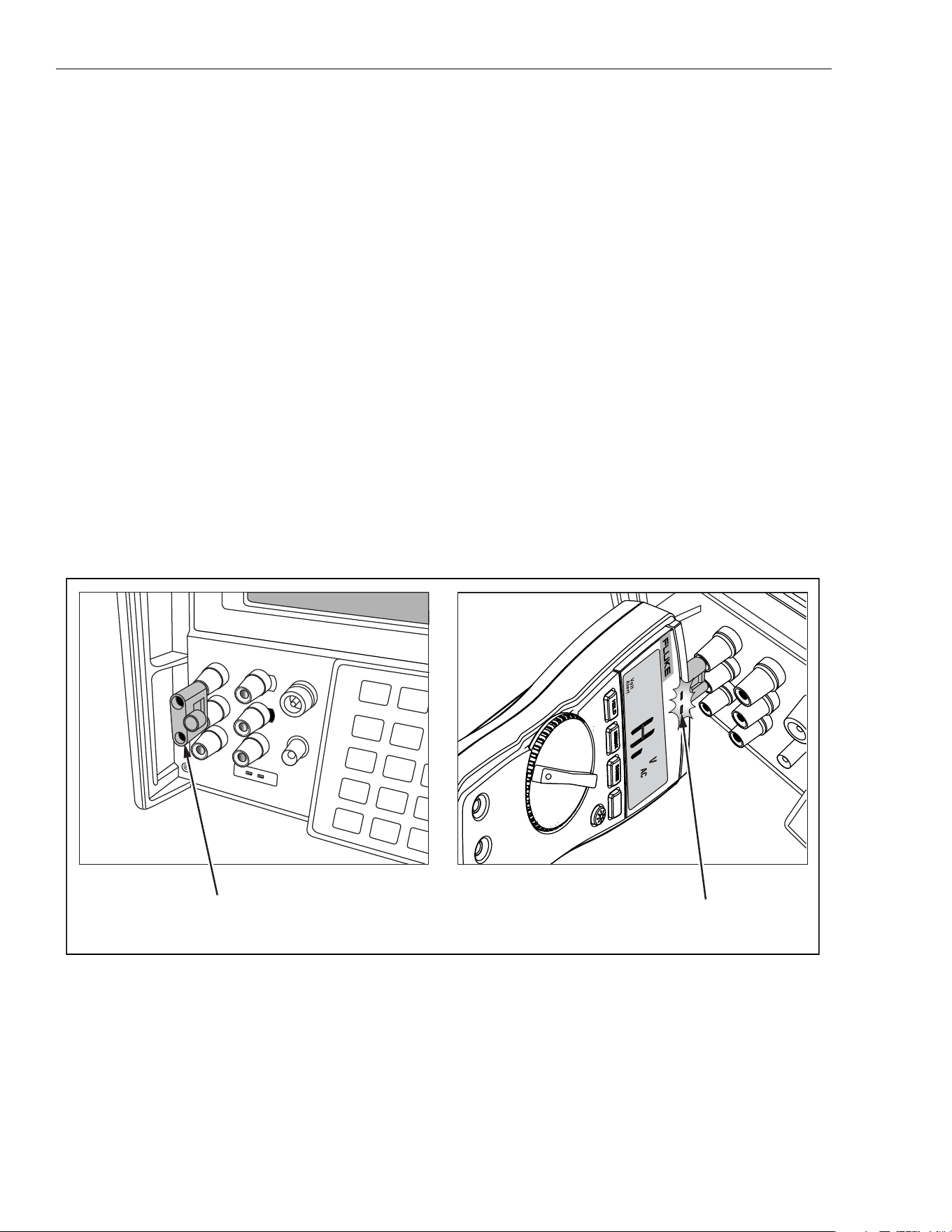
Refer to Figure 4 for these steps:
1. Select the VoltAlert function and verify that
Hiis on the display. Verify that the beeper is silent and the red
LE
D is off.
2. Connect a double banana plug to the output voltage terminals of the calibrator (Fluke 5500A or equivalent).
3. Set the calibrator output to 10 V at 60 Hz.
4. Hold the Meter so that the top is vertically and horizontally centered and contacting the banana plug
Hi
ter
minal. Verify that the Meter beeper is on continuously and the red LED at the top of the display lights.
5. Place the calibrator in standby mode and verify that the beeper is now silent and the red LED is off.
6. Press q(display should indicate
Lo range).
7. Set the calibrator output to 30 V at 60 Hz.
Figure 4. VoltAlert Test
8. Hold the Meter so that the top is vertically and horizontally centered to the banana plug Hi terminal. Verify
tha
t the Meter beeper is sounding continuously and the red LED at the top of the display lights.
9. Return the calibrator to standby mode and verify the Meter beeper is silent and the red LED is off.
S
T
B
Y
7
8
2
5
0
+
/
-
4
.
.
S
C
O
P
E
O
U
T
T
R
I
G
A
U
X
A
S
E
N
S
E
A
U
X
V
N
O
R
M
A
L
V
R
T
D
T
R
U
E
R
M
S
M
U
L
T
I
M
ET
E
R
1
1
7
V
o
l
t
A
l
e
r
t
Center Meter top on Hi terminal.
Note that LED is RED
Insert Double Banana
1.888.610.7664 sales@GlobalTestSupply.com
Fluke-Direct.com
True-rms Multimeter
Performance Tests
13
For Fluke 117 with S/N 38920290 through 42913406, use this alternate calibration procedure to verify that
VoltAlert functions properly. See Figure 5.
1. Select the VoltAlert function:
a. Verify that Hi is on the displa
y.
b
. Verify that the beeper is silent and the red LED
is off.
2.
Connect wire (Pomona 4911A-12-2 or equivalent) to the High output voltage terminals of the calibra
tor
(F
luke 5500A or equivalent).
3. Set the calibrator output to 10 V at 60 Hz
.
4.
Hold the Meter so that the wire contacts and runs across the top center of the unit. The wire should ru
n
pe
rpendicular to the face of the unit (front to back of Meter, not side to side). Verify that the Meter beepe
r is
on
continuously and the red LED, at the top of the display, lights up
.
5.
Place the calibrator in standby mode and verify that the beeper is silent and the red LED is of
f.
6.
Press q.
Display should indicate
Lo range.
7.
Set the calibrator output to 30 V at 60 Hz
.
8.
Hold the Meter so that the wire contacts and runs across the top center of the unit. The wire should ru
n
pe
rpendicular to the face of the unit (front to back of Meter, not side to side). Verify that the Meter beepe
r is
on
continuously and the red LED, at the top of the display, lights up
.
9. Return the calibrator to standby mode and verify the Meter’s beeper is silent and the red LED is off.
Figure 5. Volt Alert Test (Alternate)
0 •
123
456
789
/
+
OPR EARTH
20V PK
MAX
HI
LO
TC
TRIG
OUT
1000V
RMS
MAX
20V
RMS
MAX
1V PK
MAX
20V PK
MAX
NORMAL AUX
SCOPE
V, ,
RTD
A, -SENSE,
AUX V
200V PK
MAX
STBY
30.000 V
60.00 Hz
OPR
VoltAlert
10 A
FUSED
COM
V
A
Lo / H
OFF
Hz
A
V
Hz
A
mV
MIN MAX RANGE
TRUE RMS MULTIMETER
117
HOLD
Volt
Alert
1.888.610.7664 sales@GlobalTestSupply.com
Fluke-Direct.com

110/113/114/115/116/117
Calibration Information
14
Calibration Adjustment
The Meter features closed-case calibration adjustment using known reference sources. The Meter measures
the applied reference source, calculates correction factors, and stores the correction factors in nonvolatile
memory. The following sections present the features and Meter pushbutton functions available during the
Calibration Adjustment Procedure. Should the Meter fail any of the performance tests, perform the Calibration
Adjustment Procedure.
110/114/115/116/117
Use these steps to view the Meter calibration counter:
1. While pressing K, turn the rotary switch from OFF to Ω function. The Meter should display ZCAL.
2. Press gonce to view the calibration counter. For example, n001.
3. Turn the rotary switch to OFF.
113
1. While pressing q, turn the rotary switch from OFF to Ω function. The Meter should display ZCAL.
2. Press gonce to view the calibration counter. For example, n001.
3. Turn the rotary switch to OFF.
Calibration Adjustment Password
To start the Calibration Adjustment Procedure, the correct 4-digit password must be entered. The default
password is1234. The password can be changed or reset to the default as described in following paragraphs.
Changing the Password
Use these steps to change the Meter password:
1. 110/114/115/116/117:
While pressing K, turn the rotary switch from OFF to Ω function.
113:
While pressing q, turn the rotary switch from OFF to Ω function
.
Th
e Meter should display ZCAL.
2. Press g once to see the calibration counter.
3. Press g again to start the password en
try.
Th
e Meter displays ?.?.?.?
.
The Meter buttons indicated below represent the numbers 1 through 5 when you enter or change the
password:
K = 1 M = 2 q = 3 g = 4 Q = 5
4. Press 4 buttons to enter the current password. To change the password for the first time, enter
K (1), M (2), q (3), and g (4).
5. Press qto change the password.
The Meter displays //// if the entered password is correct. If the password is not correct, the Meter emits
a
d
ouble beep, displays ?.?.?.?, and the password must be entered again.
Repeat step 4.
6. Press the 4 buttons of the new password.
7. Press g to store the new password.
1.888.610.7664 sales@GlobalTestSupply.com
Fluke-Direct.com
True-rms Multimeter
Calibration Adjustment
15
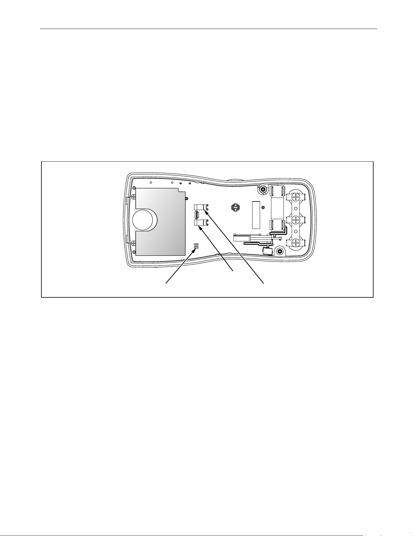
Restoring the Default Password
If the calibration password is forgotten, the default password (1234) can be manually restored:
XW Warning
To prevent electric shock or personal injury, remove the test leads and any input signal before
removing the Meter’s back case.
1. Remove the Meter back case. Leave the PCA in the top case.
2. Apply 9.0 V across the battery contacts (XBT1) + and (XBT2) – on the back of the PCA. See Figure 6.
3. Turn the rotary switch from OFF to any ON position.
4. Short across the S7 CAL keypad on the back of the PCA. See Figure 6. The Meter should beep. The defaul
t
pas
sword is now restored.
5. Remove the 9.0 V supply and replace the Meter back case.
Figure 6. Calibration Password Reset
Short S7 to reset to Default password XBT1
XBT2
1.888.610.7664 sales@GlobalTestSupply.com
Fluke-Direct.com

110/113/114/115/116/117
Calibration Information
16
Meter Buttons Used in the Calibration Steps
For the Calibration Adjustment Procedure, the Meter buttons behave as follows:
• Press and hold K to show the measured value. The measured value is not calibrated so it may
not match the
input value.
This is normal.
• Press and hold M to display the required input value.
•Press g to store the calibration value and advance to the next step. This button is
also used to exit calibration
mode after the calibration adjustment sequence is complete.
•Press Q to toggle the backlight on and off.
This can be useful to determine why a calibration step is not accepted and to determine the input value without
referring to Table 5.
Calibration Adjustment Procedure
Note
If you turn off the Meter before completion of the adjustment procedure, the
calibration constants do not change.
To adjust the Meter calibration:
1. 110/114/115/116/117:
While pressing K, turn the rotary switch from OFF to Ω function.
113:
While pressing q, turn the rotary switch from OFF to Ω function
.
Th
e Meter should display ZCAL.
2. Press g once to see the calibration counter.
3. Press g again to start the password en
try.
Th
e Meter displays ?.?.?.?
.
4. Press the 4-button password.
5. Press g to go to the first calibration step. The Meter displays C01 if the password is correct. If th
e
p
assword is not correct, the Meter emits a double beep, displays ?.?.?.? and the password must be entere
d
a
gain. Repeat step 4.
6. Apply the input value listed for each calibration adjustment step. For each step, select the rotary sw
itch
p
osition and apply the input to the terminals as indicated in Table 5 and Table 6.
Note
Some adjustment steps require additional wait time after the calibrator settles,
as noted in Table 5 and Table 6.
7. After each input value is applied, press g to accept the value and proceed to the next step (C002).
Note
After you press g, wait until the step number advances before you change
the calibrator source or turn the rotary switch. Some adjustment steps can
take up to several seconds to execute before the next step.
If the rotary switch is not in the correct position for a given step, the meter will
flash the unit annunciators until the rotary switch is put in a valid position. The
keys that show the reading and required input values are not allowed until the
rotary switch is correct.
If the rotary switch is not in the correct position or the measured value is not
within the anticipated range of the input value, the Meter will emit a double
beep and will not continue to the next step when you press g.
After the final step, the display shows End to indicate that the calibration adjustment is complete.
8. Press g to return to meter mode.
1.888.610.7664 sales@GlobalTestSupply.com
Fluke-Direct.com

True-rms Multimeter
Calibration Adjustment
17
Note
Set the calibrator to Standby before you change the function switch position
and after you complete adjustment of each function.
If the calibration adjustment procedure is not properly completed, the Meter
will not operate correctly.
Table 5. Calibration Adjustment Steps (110/114/115/116/117)
Rotary
Switch
Position
Display Reading
Input
Terminals
Calibrator
Source Value
110/114
115
[1]
116
[1]
117
[1, 2]
Ω
Ohms
NA
C001
C001
C001
[2]
no leads no leads
m
C001 C002 C002 C002
VΩ/+ and COM 0 V, 0 Hz
C002 C003 C003 C003
VΩ/+ and COM 300 mV, 0 Hz
C003 C004 C004 C004
VΩ/+ and COM 100 mV, 0 Hz
C004 C005 C005 C005
VΩ/+ and COM -300 mV, 0 Hz
C005 C006 C006 C006
VΩ/+ and COM 60 mV, 0 Hz
C006 C007 C007 C007
VΩ/+ and COM 600 mV, 0 Hz
C007 C008
C008 C008
VΩ/+ and COM 600 MV, 60 Hz
Ω
Ohms
C008 C009 C009 C009
VΩ/+ and COM 600 Ω, 2-wire comp
C009 C010 C010 C010
VΩ/+ and COM 6 kΩ
C010 C011 C011 C011
VΩ/+ and COM 60 kΩ
C011 C012 C012 C012
VΩ/+ and COM 600 kΩ
C012 C013 C013 C013
VΩ/+ and COM 6 MΩ
[3]
C013 C014 C014 C014
VΩ/+ and COM short
[3]
C014 C015
C015 C015
VΩ/+ and COM 40 MΩ
[3]
C015 C016 C016 C016
VΩ/+ and COM 6 V, 60 Hz
C016 C017 C017 C017
VΩ/+ and COM 60 V, 60 Hz
C017 C018 C018 C018
VΩ/+ and COM 600 V, 60 Hz
C018 C019 C019 C019
VΩ/+ and COM 6 V, 0 Hz
C019 C020 C020 C020
VΩ/+ and COM 60 V, 0 Hz
C020 C021
C021 C021
VΩ/+ and COM 600 V, 0Hz
1.888.610.7664 sales@GlobalTestSupply.com
Fluke-Direct.com
110/113/114/115/116/117
Calibration Information
18
Table 6. Calibration Adjustment Steps (113)
Set calibrator to standby, reconfigure leads, and program for amps output.
NA
C022
NA
C022
A and COM 6 A, 60 Hz
[3]
NA
C023
NA
C023
A and COM 6 A, 0 Hz
$
DC μAmps
NA NA C022 NA + and COM 600 μA, 60 Hz
NA NA
C023 NA + and COM 600 μA, 0 Hz
[1] Models listed in this column also refer to the “C” version of the model. For example, model 115 steps are valid for the 115C.
[2] Do not calibrate the 117 or 117C with a line-frequency power source nearby (for example, fluorescent light or power strip).
These
devices ca
n produce errors in the VoltAlert calibration.
[3] Wait an additional 5 seconds after calibrator has settled before pressing g.
Rotary Switch
Position
Calibration Steps Input Terminals Calibrator Source Value
k CHEK
mV ac/dc
C/01 + and COM 0 V, 0 Hz
C/02 + and COM 300 mV, 0 Hz
C/03 + and COM 100 mV, 0 Hz
C/04 + and COM -300 mV, 0 Hz
C/05 + and COM 60 mV, 0 Hz
C/06 + and COM 600 mV, 0 Hz
C/07 + and COM 600 mV, 60 Hz
Ω
Ohms
C/08 + and COM 600 e, 2-wire comp
C/09 + and COM 6 ke
C/10 + and COM 60 ke
C/11 + and COM 600 ke
k CHEK
V ac
C/12 + and COM 6 V, 60 Hz
C/13 + and COM 60 V, 60 Hz
C/14 + and COM 600 V, 60 Hz
[1]
[1] To keep from tripping the calibrator to standby, ramp up the voltage in 50 V increments with a 5 second delay between increments.
Table 5. Calibration Adjustment Steps (110/114/115/116/117) (cont.)
Rotary
Switch
Position
Display Reading
Input
Terminals
Calibrator
Source Value
110/114
115
[1]
116
[1]
117
[1, 2]
1.888.610.7664 sales@GlobalTestSupply.com
Fluke-Direct.com

True-rms Multimeter
Replacement Parts
19
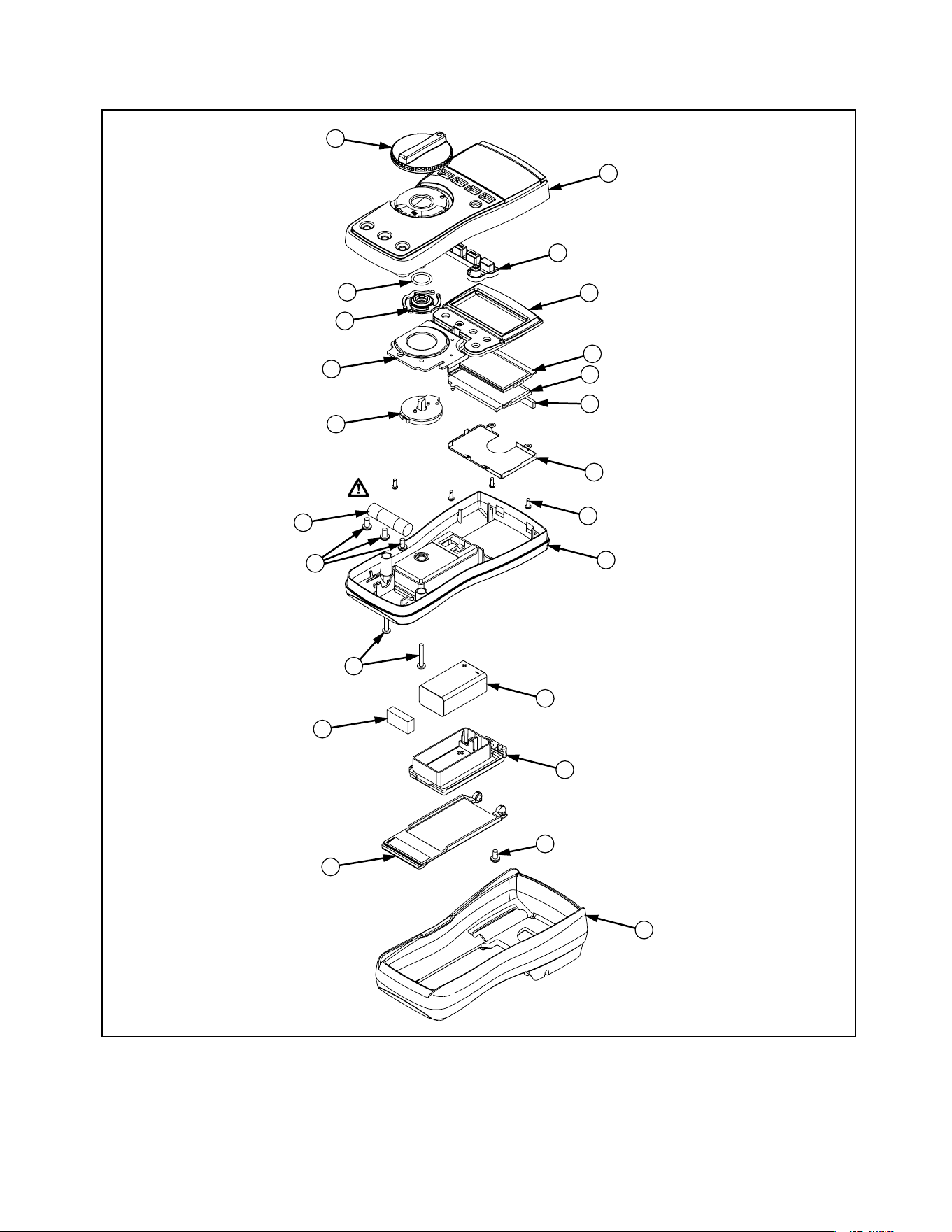
Replacement Parts
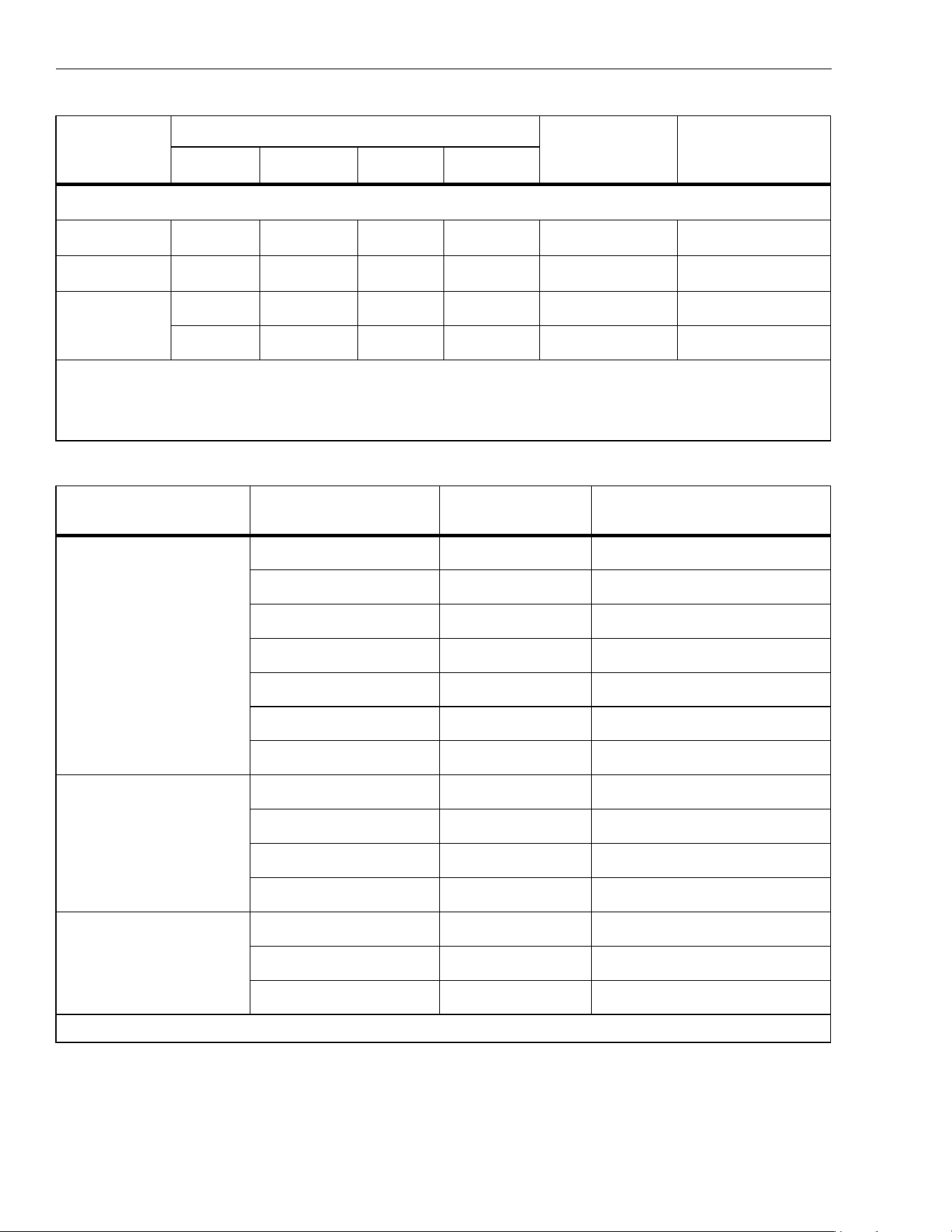
See Table 7 and Figure 7 for information about replaceable parts.
Table 7. Replacement Parts
Item Description Part Number QTY
LCD,FLUKE-11X,3.2V,TN,4-DIGIT,1/4-DUTY,1/3-BIAS,LEPTON 2509955 1
CONNECTOR,ELASTOMERIC,.010 IN CTR,.218 IN HIGH,.090 IN
THK,2.284 IN LONG,BULK
2534229 1
FLUKE-117-2006,BRACKET MASK, 117
2525608 1
FLUKE-117-2006-06,BRACKET MASK, 117 China
2631059 1
FLUKE-117-2006-08,BRACKET MASK, 113 3088082 1
FLUKE-117-2006-01,BRACKET MASK, 114 2527431 1
FLUKE-117-2006-02,BRACKET MASK, 115 2527446 1
FLUKE-117-2006-04,BRACKET MASK, 115 China 2631032 1
FLUKE-117-2006-03,BRACKET MASK, 116 2527454 1
FLUKE-117-2006-05,BRACKET MASK, 116 China 2631044 1
FLUKE-117-8005,DIFFUSER, BACKLIGHT 2535203 1
FLUKE-117-2001,CASE TOP, 117 2525553 1
FLUKE-117-2001-07,CASE TOP, 110 5166573 1
FLUKE-117-2001-04,CASE TOP, 113 3092058 1
FLUKE-117-2001-01,CASE TOP, 114
2527405 1
FLUKE-117-2001-02,CASE TOP, 115
2527410 1
FLUKE-117-2001-03,CASE TOP, 116
2527422 1
FLUKE-117-2008,KNOB
2525624 1
FLUKE-117-7602,RSOB HOUSING ASSEMBLY
2787083 1
FLUKE-117-8001,KEYPAD
2526276 1
FLUKE-117-2009,SPRING DETENT
2525636 1
FLUKE-117-8009,SHIELD, TOP
2571277 1
FLUKE-117-8010,IC SHIELD
2571292 1
O-RING,NITRILE,SHORE A 70,15.6MM OD,12.0MM ID,1.8MM W
2535215 1
1.888.610.7664 sales@GlobalTestSupply.com
Fluke-Direct.com

110/113/114/115/116/117
Calibration Information
20
FLUKE-117-2002,CASE BOTTOM
2525566 1
FLUKE-117-2002,CASE BOTTOM, 11X China
2631098 1
FLUKE-117-2003,BATTERY DOOR,TILT STAND
2720600 1
FLUKE-117-2003,BATTERY DOOR, TILT STAND, 11X China 2720617 1
SCREW,2-28,.250,PAN,PHILLIPS,STEEL,ZINCCHROMATE,
PLASTITE 48 THREAD FORMING
2516493 4
SCREW,M3,4MM,PAN,PHILLIPS,STEEL,ZINC-CHROMATE
2032811
2 (114, 110, 116)
3 (115,117)
SCREW,5-14,.750,PAN,PHILLIPS,STEEL,BLACK CHROMATE,
THD FORMING
832246 2
SCREW,M3X0.5,6MM,PAN,PHILLIPS,STEEL,ZINC-BLACK
CHROMATE
2032792 1
BATTERY,PRIMARY,MNO2-ZN,9V,505MAH,6LR61,
ALKALINE, 17X26X48MM,BULK
614487 1
FLUKE 12-8004,SHOCK ABSORBER 878983 1
FLUKE-117-2010,HOLSTER 2525649 1
FLUKE-117-2010,HOLSTER, 11X China 2631080 1
FUSE,11A,1000V,FAST.406INX1.5IN,BULK 803293 1 (115, 117)
not
shown
110/113/114/115/117 Users Manual
not
shown
1
16 Users Manual
Table 7. Replacement Parts (cont.)
Item Description Part Number QTY
1.888.610.7664 sales@GlobalTestSupply.com
Fluke-Direct.com
True-rms Multimeter
Replacement Parts
21
Figure 7. Exploded View of Meter
6
12
10
23
20
17
21
9
7
5
8
1
3
4
2
11
15 4 PL
2 PL
13
19
14
18
22
16
1.888.610.7664 sales@GlobalTestSupply.com
Fluke-Direct.com