
®
80 Series V
Multimeters
Users Manual
May 2004 Rev.2, 11/08
©2004, 2008 Fluke Corporation. All rights reserved.
Specifications are subject to change without notice.
All product names are trademarks of their respective companies.
1.888.610.7664 sales@GlobalTestSupply.com
Fluke-Direct.com

Lifetime Limited Warranty
Each Fluke 20, 70, 80, 170 and 180 Series DMM will be free from defects in material and workmanship for its lifetime. As used herein,
“lifetime” is defined as seven years after Fluke discontinues manufacturing the product, but the warranty period shall be at least ten years from
the date of purchase. This warranty does not cover fuses, disposable batteries, damage from neglect, misuse, contamination, alteration,
accident or abnormal conditions of operation or handling, including failures caused by use outside of the product’s specifications, or normal
wear and tear of mechanical components. This warranty covers the original purchaser only and is not transferable.
For ten years from the date of purchase, this warranty also covers the LCD. Thereafter, for the lifetime of the DMM, Fluke will replace the LCD
for a fee based on then current component acquisition costs.
To establish original ownership and prove date of purchase, please complete and return the registration card accompanying the product, or
register your product on . Fluke will, at its option, repair at no charge, replace or refund the purchase price of a defective
product purchased through a Fluke authorized sales outlet and at the applicable international price. Fluke reserves the right to charge for
importation costs of repair/replacement parts if the product purchased in one country is sent for repair elsewhere.
If the product is defective, contact your nearest Fluke authorized service center to obtain return authorization information, then send the
product to that service center, with a description of the difficulty, postage and insurance prepaid (FOB Destination). Fluke assumes no risk
for damage in transit. Fluke will pay return transportation for product repaired or replaced in-warranty. Before making any non-warranty
repair, Fluke will estimate cost and obtain authorization, then invoice you for repair and return transportation.
THIS WARRANTY IS YOUR ONLY REMEDY. NO OTHER WARRANTIES, SUCH AS FITNESS FOR A PARTICULAR PURPOSE, ARE
EXPRESSED OR IMPLIED. FLUKE SHALL NOT BE LIABLE FOR ANY SPECIAL, INDIRECT, INCIDENTAL OR CONSEQUENTIAL
DAMAGES OR LOSSES, INCLUDING LOSS OF DATA, ARISING FROM ANY CAUSE OR THEORY. AUTHORIZED RESELLERS ARE
NOT AUTHORIZED TO EXTEND ANY DIFFERENT WARRANTY ON FLUKE’S BEHALF. Since some states do not allow the exclusion or
limitation of an implied warranty or of incidental or consequential damages, this limitation of liability may not apply to you. If any provision of
this warranty is held invalid or unenforceable by a court or other decision-maker of competent jurisdiction, such holding will not affect the
validity or enforceability of any other provision.
2/02
1.888.610.7664 sales@GlobalTestSupply.com
Fluke-Direct.com

Multimeters
Introduction
1
Introduction
XW Warning
Read "Safety Information" before you use the
Meter.
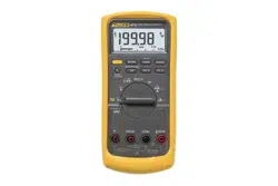
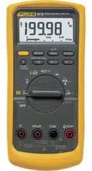
Except where noted, the descriptions and instructions in
this manual apply to Series V Models 83 and 87
multimeters (hereafter referred to as “the Meter”). Model
87 appears in all illustrations.
1.888.610.7664 sales@GlobalTestSupply.com
Fluke-Direct.com

80 Series V
Users Manual
2
Safety Information
The Meter complies with:
• EN61010-1:2001
• ANSI/ISA S82.01-2004
• CAN/CSA C22.2 No. 1010.1:2004
• UL610101-1
• Measurement Category III, 1000V, Pollution
Degree 2
• Measurement Category IV, 600V, Pollution
Degree 2
In this manual, a Warning identifies conditions and
actions that pose hazards to the user. A Caution
identifies conditions and actions that may damage the
Meter or the equipment under test.
Electrical symbols used on the Meter and in this manual
are explained in Table 1.
XW Warning
To avoid possible electric shock or personal
injury, follow these guidelines:
• Use this Meter only as specified in this
manual or the protection provided by the
Meter might be impaired.
• Do not use the Meter if it is damaged.
Before you use the Meter, inspect the
case. Look for cracks or missing plastic.
Pay particular attention to the insulation
surrounding the connectors.
• Make sure the battery door is closed and
latched before operating the Meter.
• Replace the battery as soon as the
battery indicator (M) appears.
• Remove test leads from the Meter before
opening the battery door.
1.888.610.7664 sales@GlobalTestSupply.com
Fluke-Direct.com

Multimeters
Safety Information
3
• Inspect the test leads for damaged
insulation or exposed metal. Check the
test leads for continuity. Replace
damaged test leads before you use the
Meter.
• Do not apply more than the rated
voltage, as marked on the Meter,
between the terminals or between any
terminal and earth ground.
• Never operate the Meter with the cover
removed or the case open.
• Use caution when working with voltages
above 30 V ac rms, 42 V ac peak, or 60 V
dc. These voltages pose a shock hazard.
• Use only the replacement fuses specified
by the manual.
• Use the proper terminals, function, and
range for measurements.
• Avoid working alone.
• When measuring current, turn off circuit
power before connecting the Meter in the
circuit. Remember to place the Meter in
series with the circuit.
• When making electrical connections,
connect the common test lead before
connecting the live test lead; when
disconnecting, disconnect the live test
lead before disconnecting the common
test lead.
• Do not use the Meter if it operates
abnormally. Protection may be impaired.
When in doubt, have the Meter serviced.
• Do not operate the Meter around
explosive gas, vapor, or dust.
• Use only a single 9 V battery, properly
installed in the Meter case, to power the
Meter.
• When servicing the Meter, use only
specified replacement parts.
• When using probes, keep fingers
behind the finger guards on the
probes.
• Do not use the Low Pass Filter option to
verify the presence of hazardous
voltages. Voltages greater than what is
indicated may be present. First, make a
voltage measurement without the filter to
detect the possible presence of
hazardous voltage. Then select the filter
function.
1.888.610.7664 sales@GlobalTestSupply.com
Fluke-Direct.com

80 Series V
Users Manual
4
W Caution
To avoid possible damage to the Meter or to
the equipment under test, follow these
guidelines:
• Disconnect circuit power and discharge
all high-voltage capacitors before testing
resistance, continuity, diodes, or
capacitance.
• Use the proper terminals, function, and
range for all measurements.
• Before measuring current, check the
Meter's fuses. (See "Fuse Test".)
1.888.610.7664 sales@GlobalTestSupply.com
Fluke-Direct.com
Multimeters
Safety Information
5
Table 1. Electrical Symbols
B
AC (Alternating Current)
J
Earth ground
F
DC (Direct Current)
I
Fuse
X
Hazardous voltage
P
Conforms to European Union directives.
W
Risk of Danger. Important information.
See Manual.
$
Conforms to relevant Canadian Standards
Association directives.
M
Battery. Low battery when displayed.
T
Double insulated
R
Continuity test or continuity beeper tone.
E
Capacitance
CAT
III
IEC Overvoltage Category III
CAT III equipment is designed to protect
against transients in equipment in fixed-
equipment installations, such as
distribution panels, feeders and short
branch circuits, and lighting systems in
large buildings.
CAT
IV
IEC Overvoltage Category IV
CAT IV equipment is designed to protect against
transients from the primary supply level, such as an
electricity meter or an overhead or underground utility
service.
t
Underwriters Laboratories
G
Diode
s
Inspected and licensed by TÜV Product Services.
1.888.610.7664 sales@GlobalTestSupply.com
Fluke-Direct.com
80 Series V
Users Manual
6
The Meter's Features
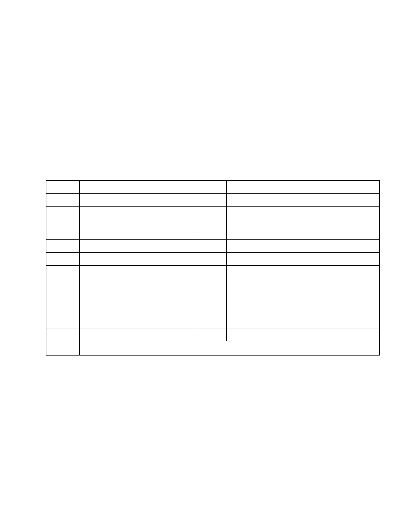
Tables 2 through 5 briefly describe the Meter's features.
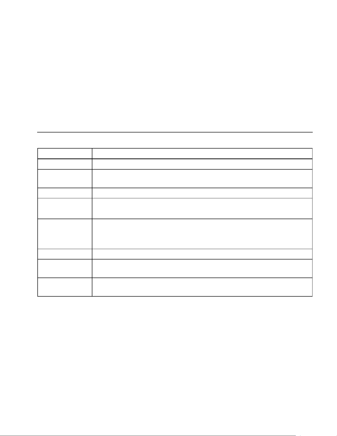
Table 2. Inputs
Terminal Description
A Input for 0 A to 10.00 A current (20 A overload for 30 seconds maximum), current frequency, and duty cycle
measurements.
mA
μ
A Input for 0 μA to 400 mA current measurements (600 mA for 18 hrs.) and current frequency and duty cycle.
COM Return terminal for all measurements.
I Input for voltage, continuity, resistance, diode, capacitance, frequency, temperature (87), and duty cycle
measurements.
1.888.610.7664 sales@GlobalTestSupply.com
Fluke-Direct.com
Multimeters
The Meter's Features
7
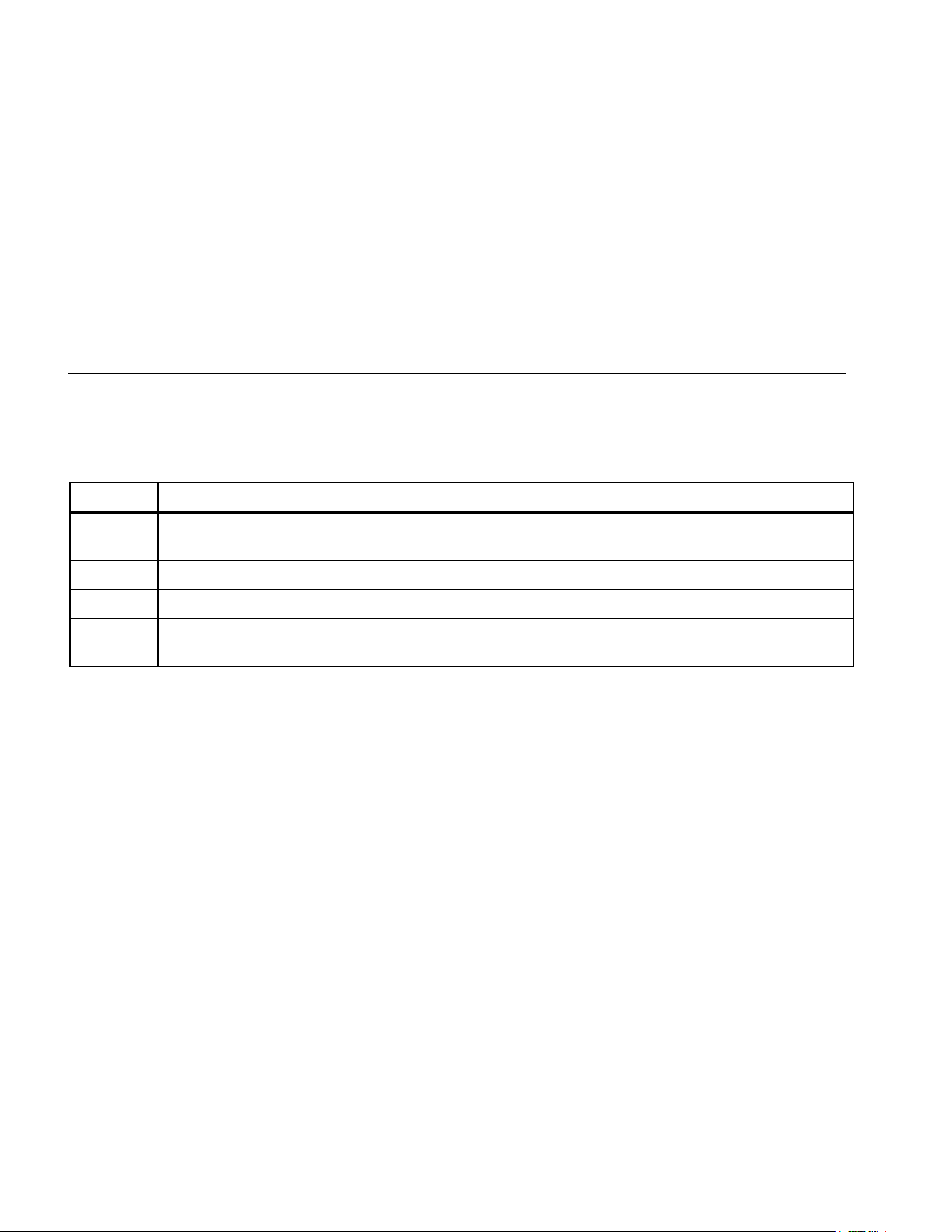
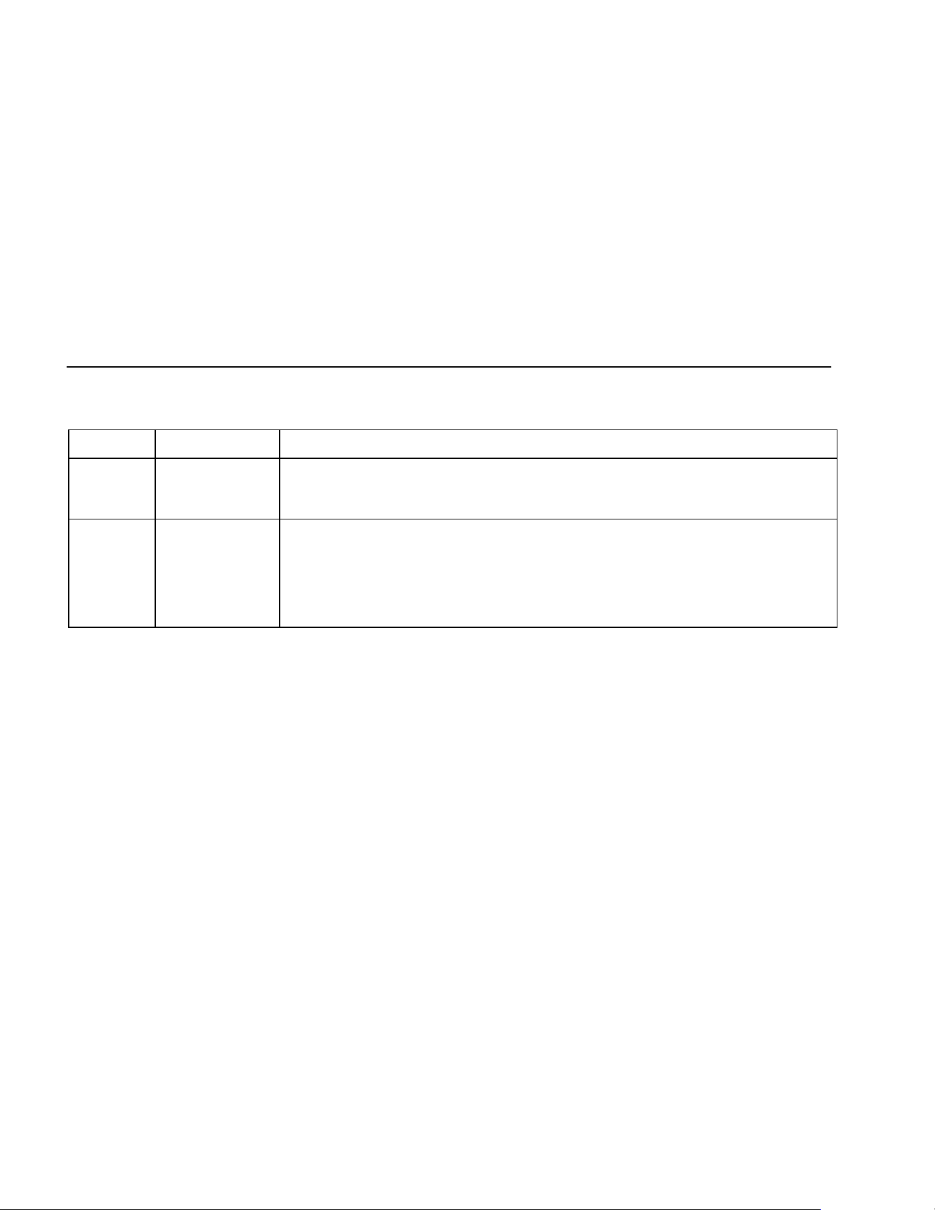
Table 3. Rotary Switch Positions
Switch Position Function
Any Position When the Meter is turned on, the Meter model number briefly appears on the display.
J
AC voltage measurement
Press
A for low pass filter (K) (87 only).
L DC voltage measurement
600 mV dc voltage range
M
Press A for temperature (T) (87 only).
N Press E for continuity test.
e Resistance measurement
Press A for capacitance measurement.
O Diode test
P
AC current measurements from 0 mA to 10.00 A
Press
A for dc current measurements, from 0 mA to 10.00 A.
Q
AC current measurements from 0 μA to 6000 μA
Press
A for dc current measurements from 0 μA to 6000 μA.
1.888.610.7664 sales@GlobalTestSupply.com
Fluke-Direct.com

80 Series V
Users Manual
8
Table 4. Pushbuttons
Button
Switch
Positon
Function
N
Selects capacitance
M
Selects temperature (87 only)
J
Selects ac low pass filter function (87 only)
P
Switches between dc and ac current
Q
Switches between dc and ac current
A
(Yellow)
Power-up Disables automatic power-off feature (Meter normally powers off in 30 minutes).
The Meter reads “PoFF” until A is released.
B
Any switch
position
Power-up
Starts recording of minimum and maximum values. Steps the display through MAX, MIN, AVG
(average), and present readings. Cancels MIN MAX (hold for 1 second)
Enables the Meter’s calibration mode and prompts for a password.
The Meter reads “CAL” and enters calibration mode. See 80 Series V Service Information.
C
Any switch
position
Switches between the ranges available for the selected function. To return to autoranging, hold
the button down for 1 second.
M
Power-up
Switches between °C and °F.
Enables the Meter’s smoothing feature. The Meter reads “5___” until C is released.
1.888.610.7664 sales@GlobalTestSupply.com
Fluke-Direct.com

Multimeters
The Meter's Features
9
Table 4. Pushbuttons (cont.)
Button
Switch
Positon
Function
D
Any switch
position
AutoHOLD (formerly TouchHold) captures the present reading on the display. When a new,
stable reading is detected, the Meter beeps and displays the new reading.
Frequency
counter
Stops and starts recording without erasing recorded values.
MIN MAX
recording
Stops and starts the frequency counter.
Power-up Turns on all LCD segments.
H
Any switch
position
Turns the backlight on, makes it brighter, and turns it off.
For Model 87, hold
H down for one second to enter the HiRes digit mode. The “HiRes” icon
appears on the display. To return to the 3-1/2 digit mode, hold
H down for one second.
HiRes=19,999
E
Continuity
ReE
Turns the continuity beeper on and off
MIN MAX
recording
Switches between Peak (250 μs) and Normal (100 ms) response times.
Hz, Duty
Cycle
Toggles the meter to trigger on positive or negative slope.
Power-up Disables the beeper for all functions. The Meter reads “bEEP” until E is released.
1.888.610.7664 sales@GlobalTestSupply.com
Fluke-Direct.com
80 Series V
Users Manual
10
Table 4. Pushbuttons (cont.)
Button Switch Positon Function
F
(Relative
mode)
Any switch
position
Power-up
Stores the present reading as a reference for subsequent readings. The display is
zeroed, and the stored reading is subtracted from all subsequent readings.
Enables zoom mode for the bar graph. The Meter reads “2rEL” until
F is released.
G
Any switch
position except
diode test
Power-up
Press G for frequency measurements.
Starts the frequency counter.
Press again to enter duty cycle mode.
Enables the Meter’s high impedance mode when the mV dc function is used.
The Meter reads “Hi2” until
G is released.
1.888.610.7664 sales@GlobalTestSupply.com
Fluke-Direct.com
Multimeters
The Meter's Features
11
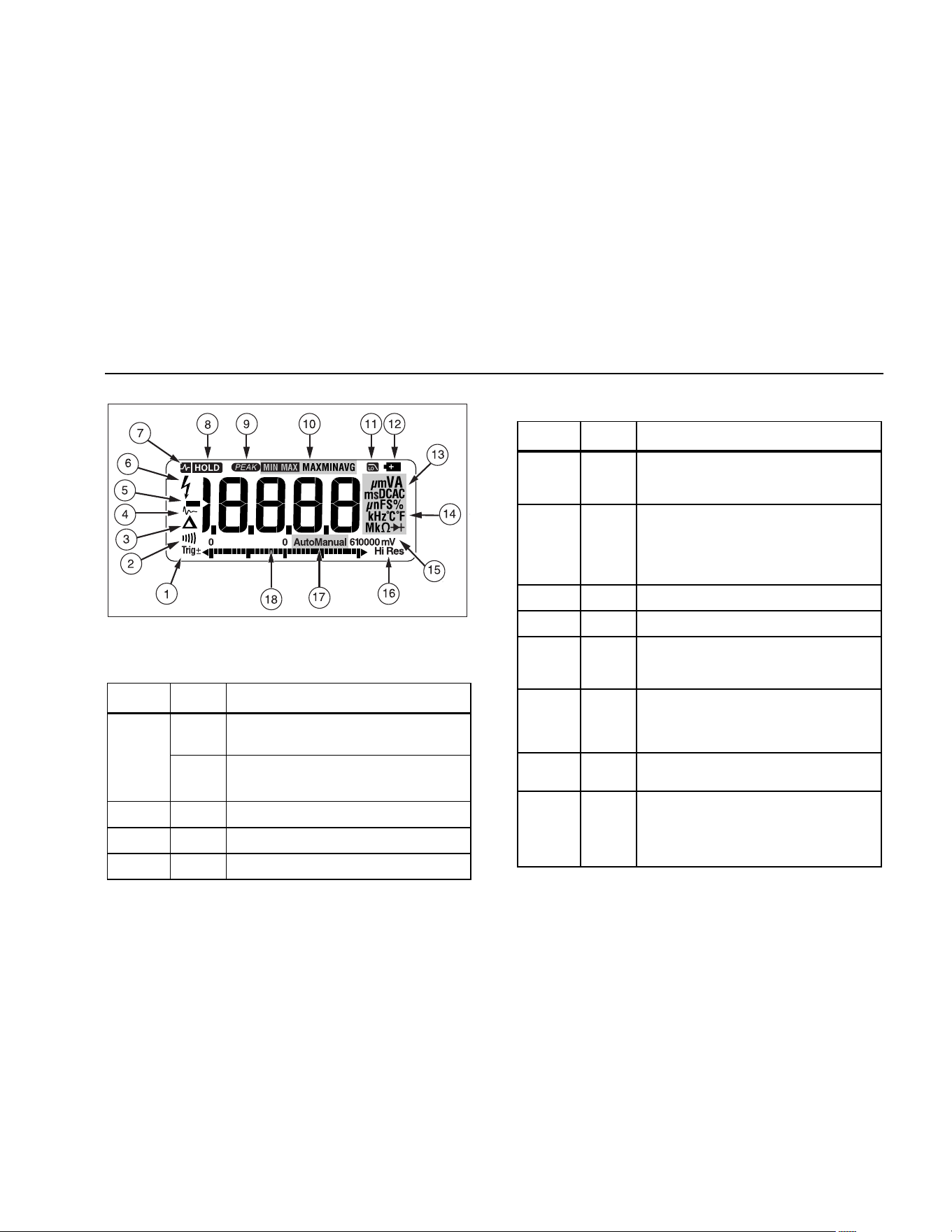
aom1_af.eps
Figure 1. Display Features (Model 87)
Table 5. Display Features
Number Feature Indication
Y
Polarity indicator for the analog bar
graph.
A
Trig
Y
Positive or negative slope indicator for
Hz/duty cycle triggering.
B X The continuity beeper is on.
C W Relative (REL) mode is active.
D g Smoothing is active.
Number Feature Indication
E
-
Indicates negative readings. In relative
mode, this sign indicates that the present
input is less than the stored reference.
F Y
Indicates the presence of a high voltage
input. Appears if the input voltage is 30 V
or greater (ac or dc). Also appears in low
pass filter mode. Also appears in cal, Hz,
and duty cycle modes.
G
RS
AutoHOLD is active.
H
S
Display Hold is active.
I p
Indicates the Meter is in Peak Min Max
mode and the response time is 250 μs
(87 only).
J
€
MAX
MIN
AVG
Indicators for minimum-maximum
recording mode.
K K
Low pass filter mode (87 only). See “Low
Pass Filter (87).
L b
The battery is low. XW Warning: To
avoid false readings, which could lead
to possible electric shock or personal
injury, replace the battery as soon as
the battery indicator appears.
1.888.610.7664 sales@GlobalTestSupply.com
Fluke-Direct.com
80 Series V
Users Manual
12
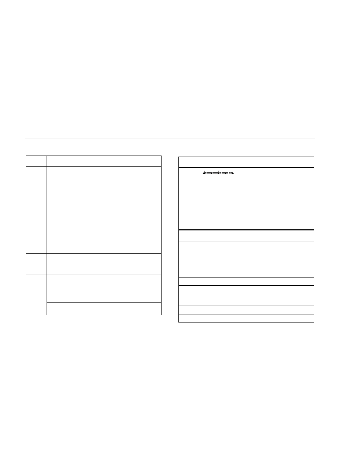
Table 5. Display Features (cont.)
Number Feature Indication
M
A, μA, mA
Amperes (amps), Microamp, Milliamp
V, mV
Volts, Millivolts
μF, nF
Microfarad, Nanofarad
nS
Nanosiemens
%
Percent. Used for duty cycle
measurements.
e, Me, ke
Ohm, Megohm, Kilohm
Hz, kHz
Hertz, Kilohertz
AC DC
Alternating current, direct current
N
°C, °F
Degrees Celsius, Degrees Fahrenheit
O
610000 mV Displays selected range
P
HiRes
The Meter is in high resolution
(Hi Res) mode. HiRes=19,999
Auto
The Meter is in autorange mode and
automatically selects the range with
the best resolution.
Q
Manual The Meter is in manual range mode.
Number Feature Indication
R
The number of segments is relative
to the full-scale value of the
selected range. In normal operation
0 (zero) is on the left. The polarity
indicator at the left of the graph
indicates the polarity of the input.
The graph does not operate with
the capacitance, frequency counter
functions, temperature, or peak min
max. For more information, see
“Bar Graph”. The bar graph also
has a zoom function, as described
under "Zoom Mode".
--
0L
Overload condition is detected.
Display Messages
bAtt
Replace the battery immediately.
diSC
In the capacitance function, too much electrical
charge is present on the capacitor being tested.
EEPr Err Invalid EEPROM data. Have Meter serviced.
CAL Err Invalid calibration data. Calibrate Meter.
LEAd
W Test lead alert. Displayed when the test leads
are in the A or mA/μA terminal and the selected
rotary switch position does not correspond to the
terminal being used.
F8/Err
Invalid model. Have Meter serviced.
OPEn
Open thermocouple is detected.
1.888.610.7664 sales@GlobalTestSupply.com
Fluke-Direct.com

Multimeters
Making Measurements
13
Power-Up Options
Holding a button down while turning the Meter on activates
a power-up option. Table 4 includes the power-up options.
Automatic Power-Off
The Meter automatically turns off if you do not turn the
rotary switch or press a button for 30 minutes. If MIN MAX
Recording is enabled, the Meter will not power off. To
disable automatic power-off, refer to Table 4.
Input Alert
™
Feature
If a test lead is plugged into the mA/μA or A terminal, but
the rotary switch is not set to the correct current position,
the beeper warns you by making a chirping sound and the
display flashes “LEAd”. This warning is intended to stop
you from attempting to measure voltage, continuity,
resistance, capacitance, or diode values when the leads
are plugged into a current terminal.
W Caution
Placing the probes across (in parallel with) a
powered circuit when a lead is plugged into a
current terminal can damage the circuit you
are testing and blow the Meter's fuse. This
can happen because the resistance through
the Meter's current terminals is very low, so
the Meter acts like a short circuit.
Making Measurements
The following sections describe how to take
measurements with the Meter.
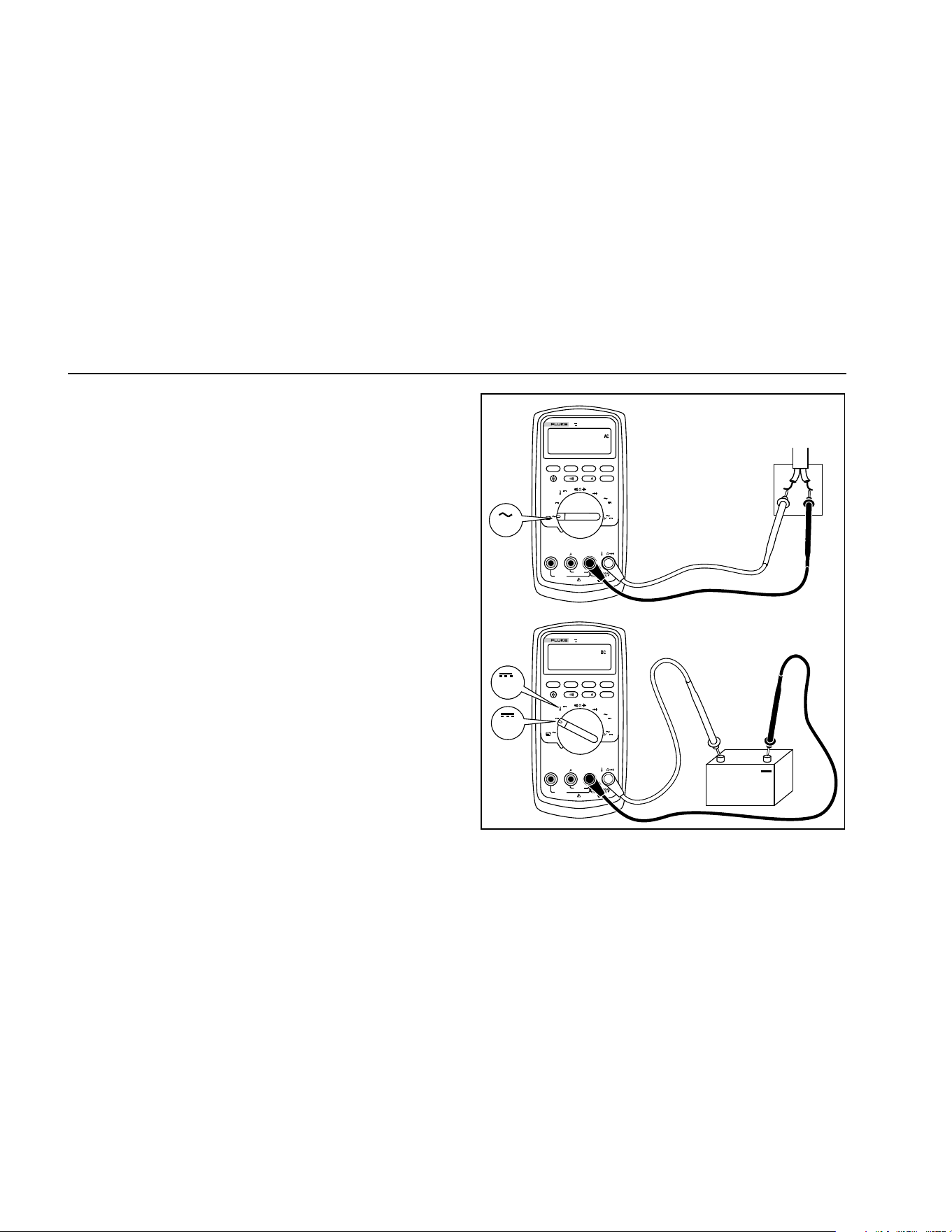
Measuring AC and DC Voltage
Model 87 features true rms readings, which are accurate
for distorted sine waves and other waveforms (with no dc
offset) such as square waves, triangle waves, and
staircase waves.
The Meter's voltage ranges are 600.0 mV, 6.000 V, 60.00
V, 600.0 V, and 1000 V. To select the 600.0 mV dc range,
turn the rotary switch to mV.
To measure ac or dc voltage, refer to Figure 2.
1.888.610.7664 sales@GlobalTestSupply.com
Fluke-Direct.com
80 Series V
Users Manual
14
When measuring voltage, the Meter acts approximately
like a 10 MΩ (10,000,000 Ω) impedance in parallel with
the circuit. This loading effect can cause measurement
errors in high-impedance circuits. In most cases, the error
is negligible (0.1% or less) if the circuit impedance is
10 kΩ (10,000 Ω) or less.
For better accuracy when measuring the dc offset of an ac
voltage, measure the ac voltage first. Note the ac voltage
range, then manually select a dc voltage range equal to or
higher than the ac range. This procedure improves the
accuracy of the dc measurement by ensuring that the
input protection circuits are not activated.
MIN MAX
RANGE
REL
Hz %
AutoHOLD
Peak MIN MAX
4½ DIGITS
1 Second
˚
C/
˚
F
OFF
mA
A
mV
V
V
A
A
mA
COM
V
400mA
FUSED
10A MAX
FUSED
A
TRUE RMS MULTIMETER
87
V
LOLO
MIN MAX
RANGE
REL
Hz %
AutoHOLD
Peak MIN MAX
4½ DIGITS
1 Second
˚
C/
˚
F
OFF
mA
A
mV
V
V
A
A
mA
COM
V
400mA
FUSED
10A MAX
FUSED
A
TRUE RMS MULTIMETER
87
V
LOLO
Switch Box
V
+
AC Voltage
DC Voltage
V
mV
aom2f.eps
Figure 2. Measuring AC and DC Voltage
1.888.610.7664 sales@GlobalTestSupply.com
Fluke-Direct.com
Multimeters
Making Measurements
15
Zero Input Behavior of True RMS Meters (87)
True Rms Meters accurately measure distorted
waveforms, but when the input leads are shorted together
in the AC functions, the meter displays a residual reading
between 1 and 30 counts. When the test leads are open,
the display readings may fluctuate due to interference.
These offset readings are normal. They do not affect the
Meter’s AC measurement accuracy over the specified
measurement ranges.
Unspecified input levels are:
• AC voltage: below 3 % of 600 mV AC, or 18 mV AC
• AC current: below 3 % of 60 mA AC, or 1.8 mA AC
• AC current: below 3 % of 600 μA AC, or 18 μA AC
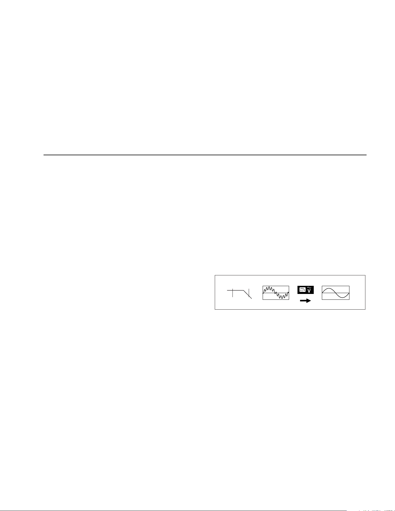
Low Pass Filter (87)
The 87 is equipped with an ac low pass filter. When
measuring ac voltage or ac frequency, press A to
activate the low pass filter mode (K). The Meter continues
measuring in the chosen ac mode, but now the signal
diverts through a filter that blocks unwanted voltages above
1 kHz, refer to Figure 3. The lower frequency voltages pass
with reduced accuracy to the measurement below 1 kHz.
The low pass filter can improve measurement performance
on composite sine waves that are typically generated by
inverters and variable frequency motor drives.
XW Warning
To avoid possible electric shock or personal
injury, do not use the Low Pass Filter option
to verify the presence of hazardous voltages.
Voltages greater than what is indicated may
be present. First, make a voltage measure-
ment without the filter to detect the possible
presence of hazardous voltage. Then, select
the filter function.
Note
In Low Pass Mode, the Meter goes to manual
mode. Select ranges by pressing the RANGE
button. Autoranging is not available in Low Pass
Mode.
1 kHz
100 Hz
aom11f.eps
Figure 3. Low Pass Filter
1.888.610.7664 sales@GlobalTestSupply.com
Fluke-Direct.com

80 Series V
Users Manual
16
Measuring Temperature (87)
The Meter measures the temperature of a type-K
thermocouple (included). Choose between degrees
Celsius (°C) or degrees Fahrenheit (°F) by pushing C.
W Caution
To avoid possible damage to the Meter or
other equipment, remember that while the
Meter is rated for –200.0 °C to +1090.0 °C and
–328.0 °F to 1994.0 °F, the included K-Type
Thermocouple is rated to 260 °C. For
temperatures out of that range, use a higher
rated thermocouple.
Display ranges are –200.0 °C to +1090.0 °C and –328.0
°F to 1994.0 °F. Readings outside of these ranges show
OL on the Meter display. When there is no thermocouple
connected, the display also reads OPEn for meters above
serial number 90710501 and OL for meters below serial
number 90710501.
Note
To locate the serial number, remove the Meter
from the holster. The serial number is on the
back of the Meter.
To measure temperature, do the following:
1. Connect a type-K thermocouple to the Meter’s COM
and dV eG
terminals.
2. Turn the rotary switch to
M.
3. Press A to enter temperature mode.
4. Push C to choose Celsius or Fahrenheit.
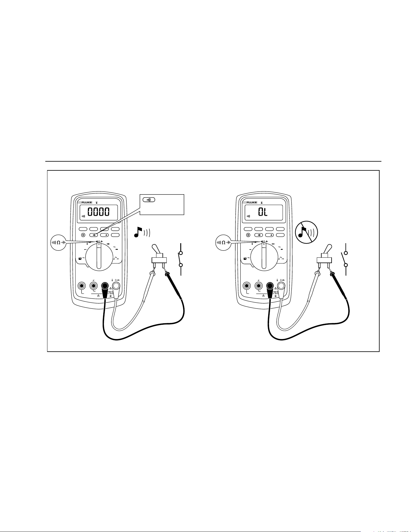
Testing for Continuity
W Caution
To avoid possible damage to the Meter or to
the equipment under test, disconnect circuit
power and discharge all high-voltage
capacitors before testing for continuity.
The continuity test features a beeper that sounds as long
as a circuit is complete. The beeper allows you to perform
quick continuity tests without having to watch the display.
To test for continuity, set up the Meter as shown in
Figure 4.
Press E to turn the continuity beeper on or off.
The continuity function detects intermittent opens and
shorts lasting as little as 1ms. A brief short causes the
Meter to emit a short beep.
1.888.610.7664 sales@GlobalTestSupply.com
Fluke-Direct.com
Multimeters
Making Measurements
17
ON
(closed)
For in-circuit tests, turn circuit power off.
MIN MAX
RANGE
REL
Hz %
AutoHOLD
Peak MIN MAX
4½ DIGITS
1 Second
˚
C/
˚
F
OFF
mA
A
mV
V
V
A
A
mA
COM
V
400mA
FUSED
10A MAX
FUSED
A
TRUE RMS MULTIMETER
87
V
LOLO
Activates
continuity
beeper
OFF
(open)
MIN MAX
RANGE
REL
Hz %
AutoHOLD
Peak MIN MAX
4½ DIGITS
1 Second
˚
C/
˚
F
OFF
mA
A
mV
V
V
A
A
mA
COM
V
400mA
FUSED
10A MAX
FUSED
A
TRUE RMS MULTIMETER
87
V
LOLO
aom4f.eps
Figure 4. Testing for Continuity
1.888.610.7664 sales@GlobalTestSupply.com
Fluke-Direct.com

80 Series V
Users Manual
18
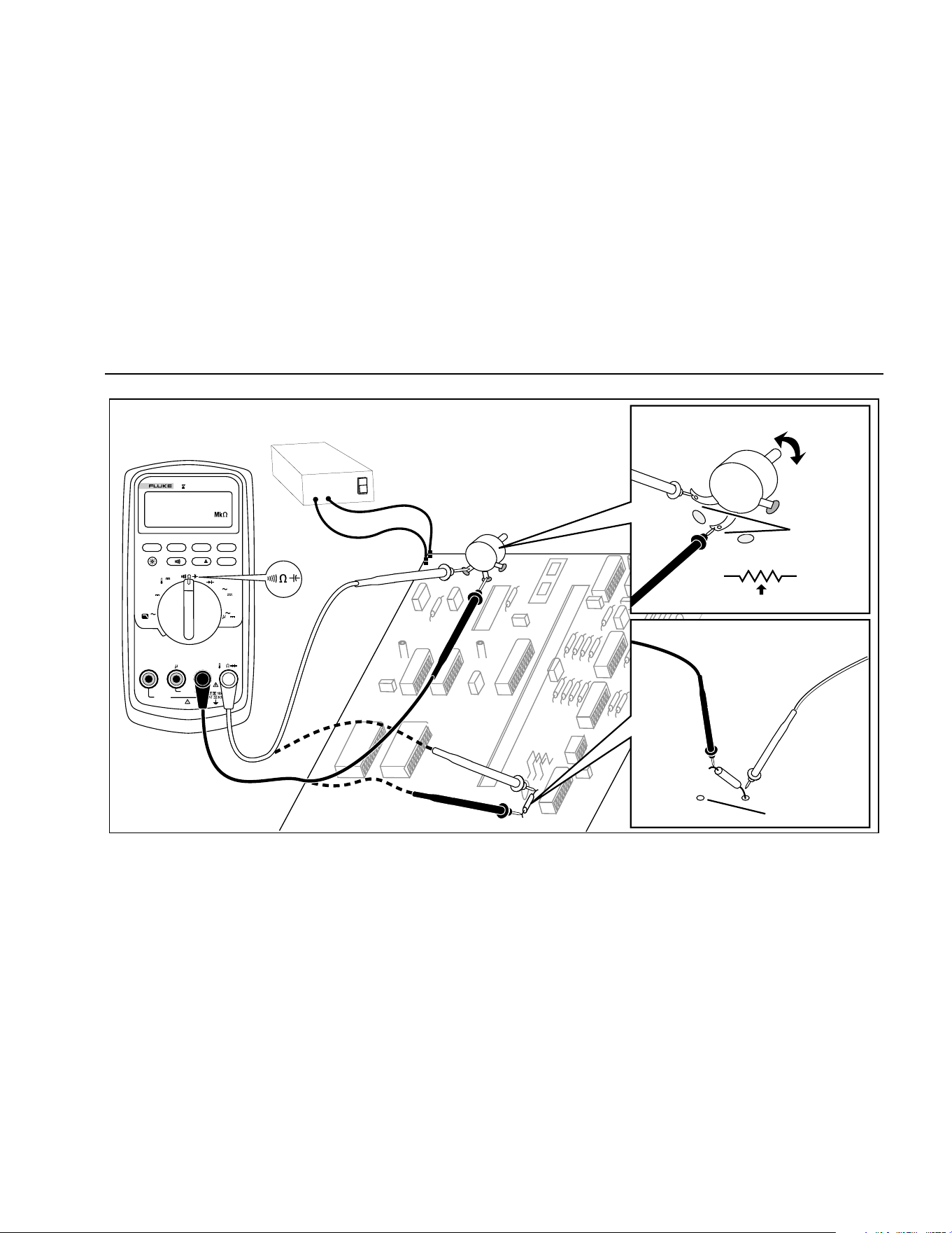
Measuring Resistance
W Caution
To avoid possible damage to the Meter or to
the equipment under test, disconnect circuit
power and discharge all high-voltage
capacitors before measuring resistance.
The Meter measures resistance by sending a small
current through the circuit. Because this current flows
through all possible paths between the probes, the
resistance reading represents the total resistance of all
paths between the probes.
The Meter's resistance ranges are 600.0 Ω, 6.000 kΩ,
60.00 kΩ, 600.0 kΩ, 6.000 MΩ, and 50.00MΩ.
To measure resistance, set up the Meter as shown in
Figure 5.
The following are some tips for measuring resistance:
• The measured value of a resistor in a circuit is often
different from the resistor's rated value.
• The test leads can add 0.1 Ω to 0.2 Ω of error to
resistance measurements. To test the leads, touch
the probe tips together and read the resistance of the
leads. If necessary, you can use the relative (REL)
mode to automatically subtract this value.
• The resistance function can produce enough voltage
to forward-bias silicon diode or transistor junctions,
causing them to conduct. If this is suspected, press
C to apply a lower current in the next higher
range. If the value is higher, use the higher value.
Refer to Table 18.
1.888.610.7664 sales@GlobalTestSupply.com
Fluke-Direct.com
Multimeters
Making Measurements
19
MIN MAX
RANGE
REL
Hz %
AutoHOLD
Peak MIN MAX
4½ DIGITS
1 Second
˚
C/
˚
F
OFF
mA
A
mV
V
V
A
A
mA
COM
V
400mA
FUSED
10A MAX
FUSED
A
TRUE RMS MULTIMETER
87
V
LOLO
Circuit Power
OFF
In-Circuit Resistance Measurements
Disconnect
1
2
3
Isolating a Potentiometer
1
3
2
Disconnect
Isolating a Resistor
aom6f.eps
Figure 5. Measuring Resistance
1.888.610.7664 sales@GlobalTestSupply.com
Fluke-Direct.com

80 Series V
Users Manual
20
Using Conductance for High Resistance or
Leakage Tests
Conductance, the inverse of resistance, is the ability of a
circuit to pass current. High values of conductance
correspond to low values of resistance.
The Meter's 60 nS range measures conductance in
nanosiemens (1 nS = 0.000000001 Siemens). Because
such small amounts of conductance correspond to
extremely high resistance, the nS range lets you
determine the resistance of components up to 100,000
MΩ, 1/1 nS = 1,000 MΩ.
To measure conductance, set up the Meter as shown for
measuring resistance (Figure 5); then press C until
the nS indicator appears on the display.
The following are some tips for measuring conductance:
• High-resistance readings are susceptible to
electrical noise. To smooth out most noisy readings,
enter the MIN MAX recording mode; then step to the
average (AVG) reading.
• There is normally a residual conductance reading
with the test leads open. To ensure accurate
readings, use the relative (REL) mode to subtract
the residual value.
1.888.610.7664 sales@GlobalTestSupply.com
Fluke-Direct.com
Multimeters
Making Measurements
21
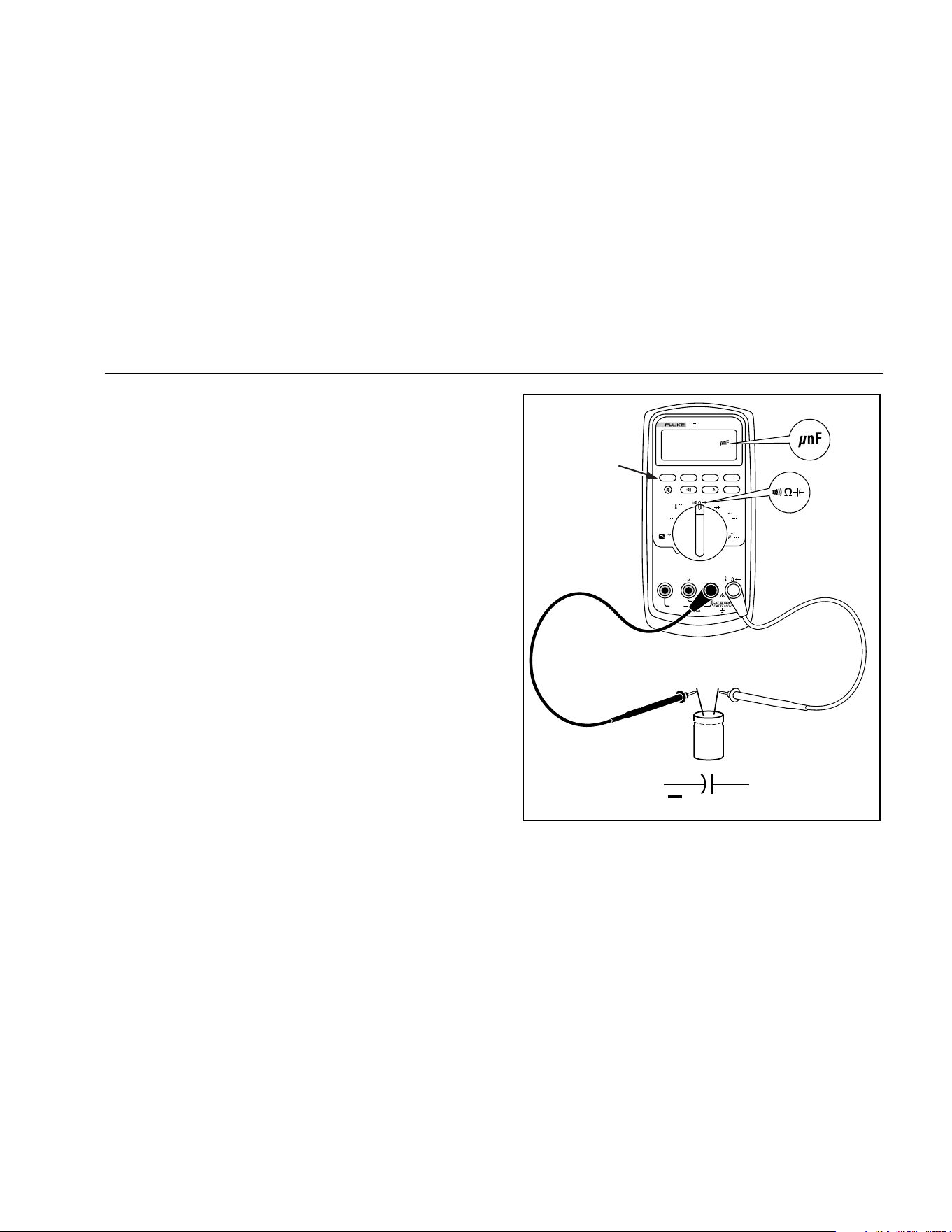
Measuring Capacitance
W Caution
To avoid possible damage to the Meter or to
the equipment under test, disconnect circuit
power and discharge all high-voltage
capacitors before measuring capacitance.
Use the dc voltage function to confirm that
the capacitor is discharged.
The Meter's capacitance ranges are 10.00 nF, 100.0 nF,
1.000 μF, 10.00 μF, 100.0 μF, and 9999 μF.
To measure capacitance, set up the Meter as shown in
Figure 6.
To improve the accuracy of measurements less than
1000 nF, use the relative (REL) mode to subtract the
residual capacitance of the Meter and leads.
Note
If too much electrical charge is present on the
capacitor being tested, the display shows
“diSC".
MIN MAX
RANGE
REL
Hz %
AutoHOLD
Peak MIN MAX
4½ DIGITS
1 Second
˚
C/
˚
F
OFF
mA
A
mV
V
V
A
A
mA
COM
V
400mA
FUSED
10A MAX
FUSED
A
TRUE RMS MULTIMETER
87
V
LOLO
Select
Capacitance
+
+
+
+
+
+
+
+
+
aom10f.eps
Figure 6. Measuring Capacitance
1.888.610.7664 sales@GlobalTestSupply.com
Fluke-Direct.com

80 Series V
Users Manual
22
Testing Diodes
W Caution
To avoid possible damage to the Meter or to
the equipment under test, disconnect circuit
power and discharge all high-voltage
capacitors before testing diodes.
Use the diode test to check diodes, transistors, silicon
controlled rectifiers (SCRs), and other semiconductor
devices. This function tests a semiconductor junction by
sending a current through the junction, then measuring
the junction's voltage drop. A good silicon junction drops
between 0.5 V and 0.8 V.
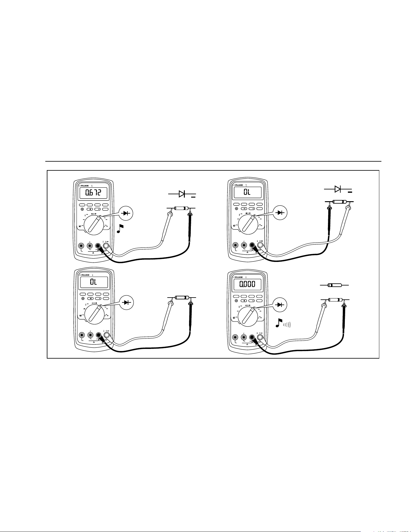
To test a diode out of a circuit, set up the Meter as shown
in Figure 7. For forward-bias readings on any
semiconductor component, place the red test lead on the
component's positive terminal and place the black lead on
the component's negative terminal.
In a circuit, a good diode should still produce a forward-
bias reading of 0.5 V to 0.8 V; however, the reverse-bias
reading can vary depending on the resistance of other
pathways between the probe tips.
A short beep sounds if the diode is good (< 0.85 V). A
continuous beep sounds if the reading is ≤ 0.100 V. This
reading would indicate a short circuit. The display shows
“OL” if the diode is open.
1.888.610.7664 sales@GlobalTestSupply.com
Fluke-Direct.com
Multimeters
Making Measurements
23
MIN MAX
RANGE
REL
Hz %
AutoHOLD
Peak MIN MAX
˚
C/
˚
F
OFF
mA
A
mV
V
V
A
A
mA
COM
V
400mA
FUSED
10A MAX
FUSED
A
TRUE RMS MULTIMETER
87
V
LOLO
+
Typical
Reading
+
Forward Bias
Reverse Bias
MIN MAX
RANGE
REL
Hz %
AutoHOLD
Peak MIN MAX
˚
C/
˚
F
OFF
mA
A
mV
V
V
A
A
mA
COM
V
400mA
FUSED
10A MAX
FUSED
A
TRUE RMS MULTIMETER
87
V
LOLO
Bad Diode
Open
MIN MAX
RANGE
REL
Hz %
AutoHOLD
Peak MIN MAX
˚
C/
˚
F
OFF
mA
A
mV
V
V
A
A
mA
COM
V
400mA
FUSED
10A MAX
FUSED
A
TRUE RMS MULTIMETER
87
V
LOLO
Bad Diode
Shorted
MIN MAX
RANGE
REL
Hz %
AutoHOLD
Peak MIN MAX
˚
C/
˚
F
OFF
mA
A
mV
V
V
A
A
mA
COM
V
400mA
FUSED
10A MAX
FUSED
A
TRUE RMS MULTIMETER
87
V
LOLO
or
Single Beep
aom9f.eps
Figure 7. Testing a Diode
1.888.610.7664 sales@GlobalTestSupply.com
Fluke-Direct.com

80 Series V
Users Manual
24
Measuring AC or DC Current
XW Warning
To avoid possible electric shock or personal
injury, never attempt an in-circuit current
measurement where the open-circuit
potential to earth is greater than 1000 V. You
may damage the Meter or be injured if the
fuse blows during such a measurement.
W Caution
To avoid possible damage to the Meter or to
the equipment under test:
• Check the Meter's fuses before
measuring current.
• Use the proper terminals, function, and
range for all measurements.
• Never place the probes across (in
parallel with) any circuit or component
when the leads are plugged into the
current terminals.
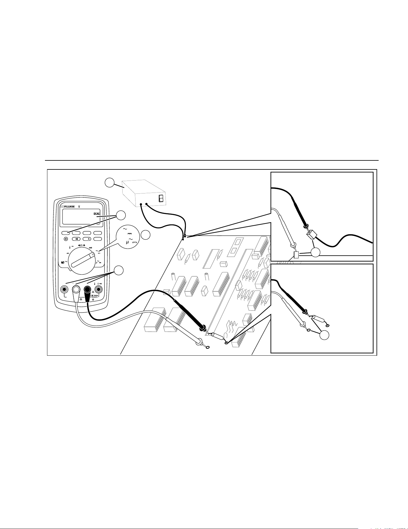
To measure current, you must break the circuit under
test, then place the Meter in series with the circuit.
The Meter's current ranges are 600.0 μA, 6000 μA,
60.00 mA, 400.0 mA, 6000 mA, and 10 A. AC current is
displayed as an rms value.
To measure current, refer to Figure 8 and proceed as
follows:
1. Turn off power to the circuit. Discharge all high-
voltage capacitors.
2. Insert the black lead into the COM terminal. For
currents between 6 mA and 400 mA, insert the red
lead into the mA/μA terminal. For currents above
400 mA, insert the red lead into the A terminal.
Note
To avoid blowing the Meter's 400 mA fuse, use
the mA/
μ
A terminal only if you are sure the
current is less than 400 mA continuously or less
than 600 mA for 18 hours or less.
1.888.610.7664 sales@GlobalTestSupply.com
Fluke-Direct.com
Multimeters
Making Measurements
25
MIN MAX
RANGE
REL
Hz %
AutoHOLD
Peak MIN MAX
4½ DIGITS
1 Second
˚
C/
˚
F
OFF
mA
A
mV
V
V
A
A
mA
COM
V
400mA
FUSED
10A MAX
FUSED
A
TRUE RMS MULTIMETER
87
V
LOLO
Circuit Power:
OFF to connect meter.
ON for measurement.
OFF to disconnect meter.
Current through one component
Total current to circuit
4
5
5
2
3
1
mA
A
A
aom7f.eps
Figure 8. Measuring Current
1.888.610.7664 sales@GlobalTestSupply.com
Fluke-Direct.com

80 Series V
Users Manual
26
3. If you are using the A terminal, set the rotary switch to
mA/A. If you are using the mA/μA terminal, set the
rotary switch to μA for currents below 6000 μA
(6 mA), or mA/A for currents above 6000 μA.
4. To measure dc current, press
A.
5. Break the circuit path to be tested. Touch the black
probe to the more negative side of the break; touch
the red probe to the more positive side of the break.
Reversing the leads will produce a negative reading,
but will not damage the Meter.
6. Turn on power to the circuit; then read the display. Be
sure to note the unit given at the right side of the
display (μA, mA, or A).
7. Turn off power to the circuit and discharge all high-
voltage capacitors. Remove the Meter and restore the
circuit to normal operation.
The following are some tips for measuring current:
• If the current reading is 0 and you are sure the Meter
is set up correctly, test the Meter's fuses as described
under "Testing the Fuses".
• A current Meter drops a small voltage across itself,
which might affect circuit operation. You can calculate
this burden voltage using the values listed in the
specifications in Table 14.
1.888.610.7664 sales@GlobalTestSupply.com
Fluke-Direct.com

Multimeters
Making Measurements
27
Measuring Frequency
The Meter measures the frequency of a voltage or current
signal by counting the number of times the signal crosses
a threshold level each second.
Table 6 summarizes the trigger levels and applications for
measuring frequency using the various ranges of the
Meter's voltage and current functions.
To measure frequency, connect the Meter to the signal
source; then press
G. Pressing E switches the
trigger slope between + and -, as indicated by the symbol
at the left side of the display (refer to Figure 9 under
"Measuring Duty Cycle"). Pressing
D stops and starts
the counter.
The Meter autoranges to one of five frequency ranges:
199.99 Hz, 1999.9 Hz, 19.999 kHz, 199.99 kHz, and
greater than 200 kHz. For frequencies below 10 Hz, the
display is updated at the frequency of the input. Below 0.5
Hz, the display may be unstable.
The following are some tips for measuring frequency:
• If a reading shows as 0 Hz or is unstable, the input
signal may be below or near the trigger level. You can
usually correct these problems by selecting a lower
range, which increases the sensitivity of the Meter. In
the L function, the lower ranges also have lower
trigger levels.
• If a reading seems to be a multiple of what you
expect, the input signal may be distorted. Distortion
can cause multiple triggerings of the frequency
counter. Selecting a higher voltage range might solve
this problem by decreasing the sensitivity of the
Meter. You can also try selecting a dc range, which
raises the trigger level. In general, the lowest
frequency displayed is the correct one.
1.888.610.7664 sales@GlobalTestSupply.com
Fluke-Direct.com
80 Series V
Users Manual
28
Table 6. Functions and Trigger Levels for Frequency Measurements
Function Range
Approximate
Trigger Level
Typical Application
K
6 V, 60 V,
600 V, 1000 V
± 5 % of scale Most signals.
K
600 mV ± 30 mV High-frequency 5 V logic signals. (The dc-coupling of the L function can
attenuate high-frequency logic signals, reducing their amplitude enough to
interfere with triggering.)
mL
600 mV 40 mV Refer to the measurement tips given before this table.
L
6 V 1.7 V 5 V logic signals (TTL).
L
60 V 4 V Automotive switching signals.
L
600 V 40 V Refer to the measurement tips given before this table.
L
1000 V 100 V
R e E Gd
Frequency counter characteristics are not available or specified for these functions.
\
All ranges ± 5 % of scale AC current signals.
μAF
600 μA, 6000 μA 30 μA , 300 μA Refer to the measurement tips given before this table.
^
60 mA, 400 mA 3.0 mA , 30 mA
AF 6 A, 10 A 0.30 A, 3.0 A
1.888.610.7664 sales@GlobalTestSupply.com
Fluke-Direct.com
Multimeters
Making Measurements
29
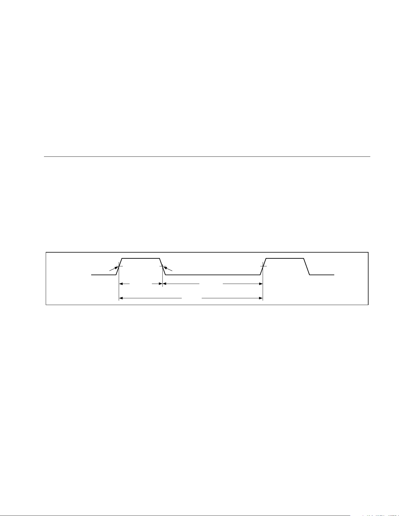
Measuring Duty Cycle
Duty cycle (or duty factor) is the percentage of time a
signal is above or below a trigger level during one cycle
(Figure 9). The duty cycle mode is optimized for
measuring the on or off time of logic and switching
signals. Systems such as electronic fuel injection systems
and switching power supplies are controlled by pulses of
varying width, which can be checked by measuring duty
cycle.
To measure duty cycle, set up the Meter to measure
frequency; then press Hz a second time. As with the
frequency function, you can change the slope for the
Meter's counter by pressing E.
For 5 V logic signals, use the 6 V dc range. For 12 V
switching signals in automobiles, use the 60 V dc range.
For sine waves, use the lowest range that does not result
in multiple triggering. (Normally, a distortion-free signal
can be up to ten times the amplitude of the selected
voltage range.)
If a duty cycle reading is unstable, press MIN MAX; then
scroll to the AVG (average) display.
-Slope
Trigger Point
+Slope
Trigger Point
30% Above
+Slope
70% Below
-Slope
100%
iy3f.eps
Figure 9. Components of Duty Cycle Measurements
1.888.610.7664 sales@GlobalTestSupply.com
Fluke-Direct.com

80 Series V
Users Manual
30
Determining Pulse Width
For a periodic waveform (its pattern repeats at equal time
intervals), you can determine the amount of time that the
signal is high or low as follows:
1. Measure the signal's frequency.
2. Press
G a second time to measure the signal's
duty cycle. Press E to select a measurement of
the signal's positive or negative pulse, refer to
Figure 9.
3. Use the following formula to determine the pulse
width:
Pulse Width = % Duty Cycle ÷ 100
(in seconds)
Frequency
Bar Graph
The analog bar graph functions like the needle on an
analog meter, but without the overshoot. The bar graph
updates 40 times per second. Because the graph
responds 10 times faster than the digital display, it is
useful for making peak and null adjustments and
observing rapidly changing inputs. The graph is not
shown for capacitance, frequency counter functions,
temperature, or peak min max.
The number of lit segments indicates the measured value
and is relative to the full-scale value of the selected
range.
In the 60 V range, for example, the major divisions on the
scale represent 0, 15, 30, 45, and 60 V. An input of -30 V
lights the negative sign and the segments up to the
middle of the scale.
The bar graph also has a zoom function, as described
under "Zoom Mode".
1.888.610.7664 sales@GlobalTestSupply.com
Fluke-Direct.com

Multimeters
HiRes Mode (Model 87)
31
Zoom Mode (Power Up Option Only)
To use the Rel Zoom Bar Graph:
1. Hold down F while turning the Meter on. The
display reads “2rEL”.
2. Select the relative mode by pressing F
again.
3. The center of the bar graph now represents zero
and the sensitivity of the bar graph increases by
a factor of 10. Measured values more negative
than the stored reference activate segments to
the left of center; values more positive activate
segments to the right of center.
Uses for the Zoom Mode
The relative mode, combined with the increased
sensitivity of the bar graph's zoom mode, helps you make
fast and accurate zero and peak adjustments.
For zero adjustments, set the Meter to the desired
function, short the test leads together, press
F; then
connect the leads to the circuit under test. Adjust the
circuit's variable component until the display reads zero.
Only the center segment on the zoom bar graph is lit.
For peak adjustments, set the Meter to the desired
function, connect the leads to the circuit under test; then
press
F. The display reads zero. As you adjust for a
positive or negative peak, the bar graph length increases
to the right or left of zero. If an overange symbol lights (<
>), press
F twice to set a new reference; then
continue with the adjustment.
HiRes Mode (Model 87)
On a Model 87 Meter, pressing H for one second causes
the Meter to enter the high-resolution (HiRes), 4-1/2 digit
mode. Readings are displayed at 10 times the normal
resolution with a maximum display of 19,999 counts. The
HiRes mode works in all modes except capacitance,
frequency counter functions, temperature, and the 250 μs
(peak) MIN MAX modes.
To return to the 3-1/2 digit mode, press H again for one
second.
1.888.610.7664 sales@GlobalTestSupply.com
Fluke-Direct.com

80 Series V
Users Manual
32
MIN MAX Recording Mode
The MIN MAX mode records minimum and maximum
input values. When the inputs go below the recorded
minimum value or above the recorded maximum value,
the Meter beeps and records the new value. This mode
can be used to capture intermittent readings, record
maximum readings while you are away or record readings
while you are operating the equipment under test and
cannot watch the Meter. MIN MAX mode can also
calculate an average of all readings taken since the MIN
MAX mode was activated. To use MIN MAX mode, refer
to the functions in Table 7.
Response time is the length of time an input must stay at
a new value to be recorded. A shorter response time
captures shorter events, but with decreased accuracy.
Changing the response time erases all recorded
readings. Model 83 has 100 millisecond response time;
Model 87 has 100 millisecond, and 250 μs (peak)
response times. The 250 µs response time is indicated by
"p" on the display.
The 100 millisecond response time is best for recording
power supply surges, inrush currents, and finding
intermittent failures.
The true average value (AVG) displayed in the 100 ms
mode is the mathematical integral of all readings taken
since the start of recording (overloads are discarded).
The average reading is useful for smoothing out unstable
inputs, calculating power consumption, or estimating the
percentage of time a circuit is active.
Min Max records the signal extremes lasting longer than
100 ms.
Peak records the signal extremes lasting longer than
250 µs.
Smooth Feature (Power Up Option Only)
When the input signal changes rapidly, “smoothing”
provides a steadier reading on the display.
To use the smooth feature:
1. Hold down C while turning the Meter on. The
display will read “
'___” until C is released.
2. The smooth icon (g) will appear on the left side
of the display to let you know that smoothing is
active.
1.888.610.7664 sales@GlobalTestSupply.com
Fluke-Direct.com
Multimeters
Smooth Feature (Power Up Option Only)
33
Table 7. MIN MAX Functions
Button MIN MAX Function
B
Enter MIN MAX recording mode. The Meter is locked in the range displayed before you
entered MIN MAX mode. (Select the desired measurement function and range before
entering MIN MAX.) The Meter beeps each time a new minimum or maximum value is
recorded.
B
(while in MIN MAX mode)
Step through maximum (MAX), minimum (MIN), average (AVG) and present values.
E
PEAK MIN MAX
Model 87 only: Select 100 ms or 250 μs response time. (The 250 µs response time is
indicated by p on the display.) Stored values are erased. The present and AVG
(average) values are not available when 250 μs is selected.
D Stop recording without erasing stored values. Press again to resume recording.
B
(hold for 1 second)
Exit MIN MAX mode. Stored values are erased. The Meter stays in the selected range.
1.888.610.7664 sales@GlobalTestSupply.com
Fluke-Direct.com

80 Series V
Users Manual
34
AutoHOLD Mode
XW Warning
To avoid possible electric shock or personal
injury, do not use AutoHOLD mode to
determine that circuits are without power.
The AutoHOLD mode will not capture
unstable or noisy readings.
The AutoHOLD mode captures the present reading on
the display. When a new, stable reading is detected, the
Meter beeps and displays the new reading. To enter or
exit AutoHOLD mode, press
D.
Relative Mode
Selecting relative mode (F) causes the Meter to zero
the display and store the present reading as the reference
for subsequent measurements. The Meter is locked into
the range selected when you pressed
F. Press
Fagain to exit this mode.
In relative mode, the reading shown is always the
difference between the present reading and the stored
reference value. For example, if the stored reference
value is 15.00 V and the present reading is 14.10 V, the
display shows -0.90 V.
1.888.610.7664 sales@GlobalTestSupply.com
Fluke-Direct.com

Multimeters
Maintenance
35
Maintenance
XW Warning
To avoid possible electric shock or personal
injury, repairs or servicing not covered in
this manual should be performed only by
qualified personnel as described in the
80 Series V Service Information.
General Maintenance
Periodically wipe the case with a damp cloth and mild
detergent. Do not use abrasives or solvents.
Dirt or moisture in the terminals can affect readings and
can falsely activate the Input Alert feature. Clean the
terminals as follows:
1. Turn the Meter off and remove all test leads.
2. Shake out any dirt that may be in the terminals.
3. Soak a new swab with a cleaning and oiling agent
(such as WD-40). Work the swab around in each
terminal. The oiling agent insulates the terminals
from moisture-related activation of the Input Alert
feature.
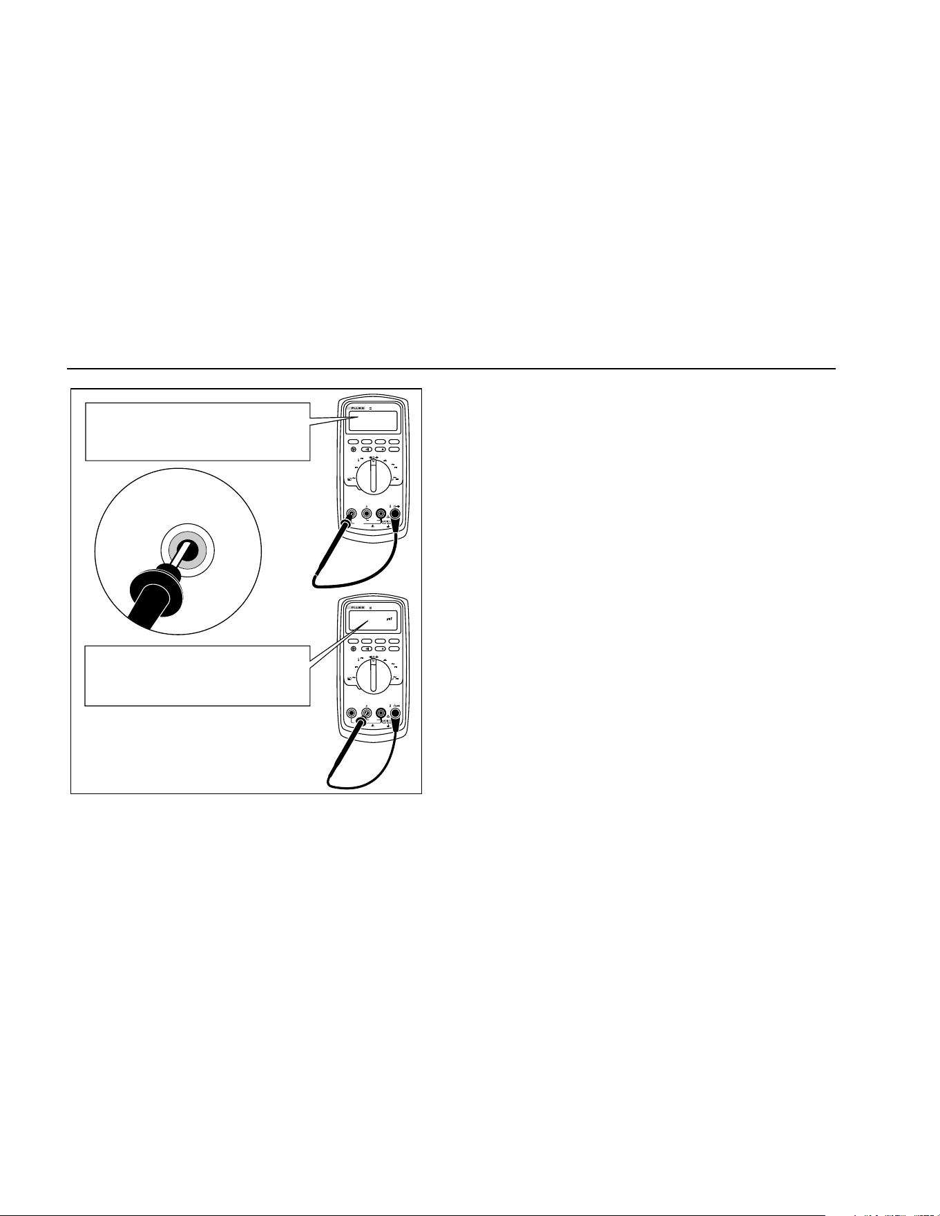
Fuse Test
If a test lead is plugged into the mA/μA or A terminal and
the rotary switch is turned to a non-current function, the
Meter chirps and flashes “LEAd” if the fuse associated
with that current terminal is good. If the Meter does not
chirp or flash “LEAd”, the fuse is bad and must be
replaced. Refer to Table 8 for the appropriate
replacement fuse.
To test the quality of the fuse before measuring current,
test the appropriate fuse as shown in Figure 10. If the
tests give readings other than those shown, have the
Meter serviced.
XW Warning
To avoid electrical shock or personal injury,
remove the test leads and any input signals
before replacing the battery or fuses. To
prevent damage or injury, install ONLY
specified replacement fuses with the
amperage, voltage, and speed ratings shown
in Table 8.
1.888.610.7664 sales@GlobalTestSupply.com
Fluke-Direct.com
80 Series V
Users Manual
36
MIN MAX
RANGE
REL
Hz %
AutoHOLD
Peak MIN MAX
4½ DIGITS
1 Second
˚
C/
˚
F
OFF
mA
A
mV
V
V
A
A
mA
COM
V
400mA
FUSED
10A MAX
FUSED
A
TRUE RMS MULTIMETER
87
V
LOLO
MIN MAX
RANGE
REL
Hz %
AutoHOLD
Peak MIN MAX
4½ DIGITS
1 Second
˚
C/
˚
F
OFF
mA
A
mV
V
V
A
A
mA
COM
V
400mA
FUSED
10A MAX
FUSED
A
TRUE RMS MULTIMETER
87
V
LOLO
Good F2 fuse: 00.0 Ω to
00.5 Ω
Good F1 fuse: 0.995 kΩ to
1.005 kΩ
Replace fuse: OL
Replace fuse: OL
Touch top half
of input contacts
aom5f.eps
Figure 10. Testing the Current Fuses
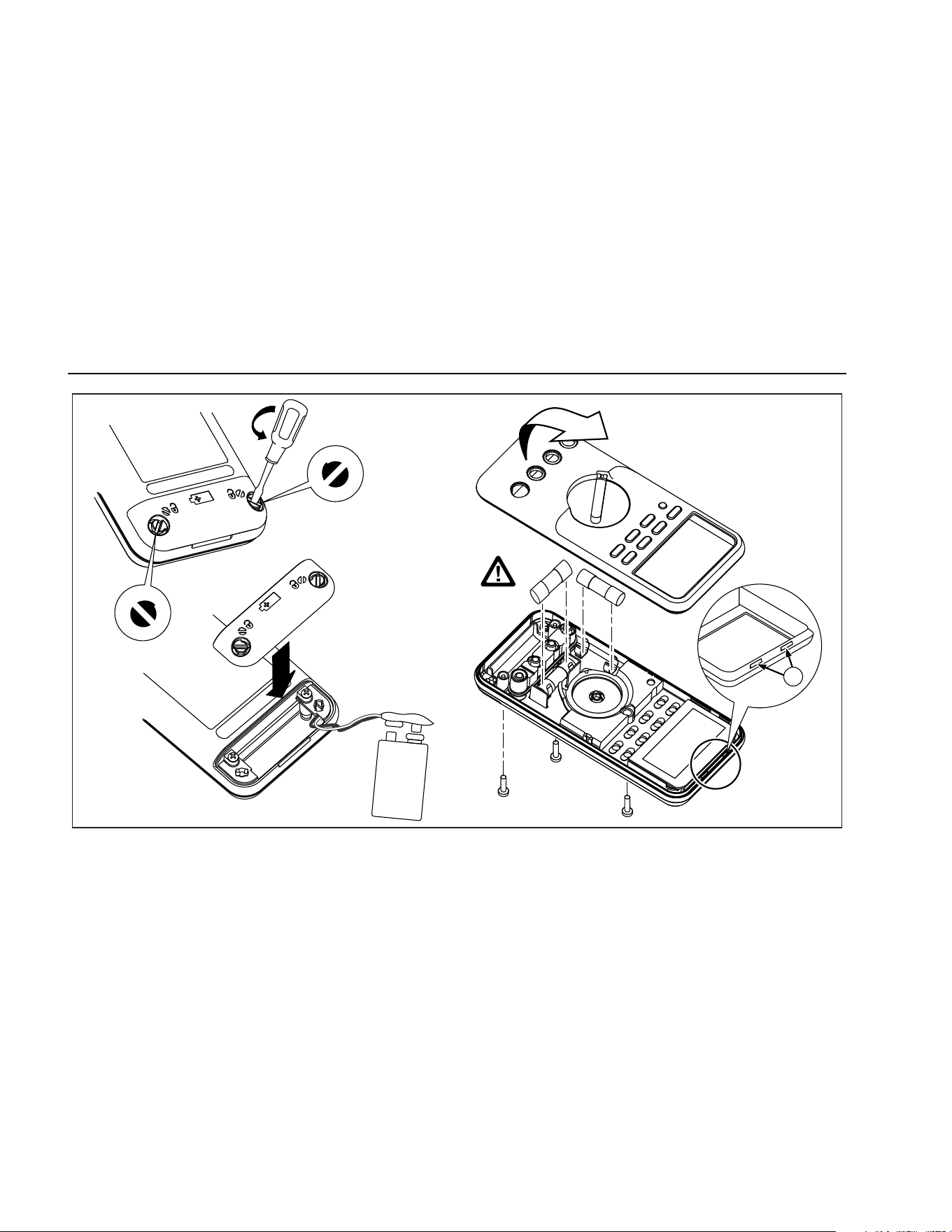
Replacing the Battery
Replace the battery with a 9 V battery (NEDA A1604,
6F22, or 006P).
XW Warning
To avoid false readings, which could lead to
possible electric shock or personal injury,
replace the battery as soon as the battery
indicator (b) appears. If the display shows
bAtt the Meter will not function until the
battery is replaced.
Replace the battery as follows, refer to Figure 11:
1. Turn the rotary switch to OFF and remove the test
leads from the terminals.
2. Remove the battery door by using a standard-blade
screwdriver to turn the battery door screws one-
quarter turn counterclockwise.
3. Replace the battery and the battery door. Secure the
door by turning the screws one-quarter turn
clockwise.
1.888.610.7664 sales@GlobalTestSupply.com
Fluke-Direct.com

Multimeters
Service and Parts
37
Replacing the Fuses
Referring to Figure 11, examine or replace the Meter's
fuses as follows:
1. Turn the rotary switch to OFF and remove the test
leads from the terminals.
2. Remove the battery door by using a standard-blade
screwdriver to turn the battery door screws one-
quarter turn counterclockwise.
3. Remove the three Phillips-head screws from the
case bottom and turn the case over.
4. Gently push up the input terminal-end of the top case
from inside of the battery compartment to separate
the two halves of the case.
5. Remove the fuse by gently prying one end loose,
then sliding the fuse out of its bracket.
6. Install ONLY specified replacement fuses with the
amperage, voltage, and speed ratings shown in
Table 8.
7. Verify that the rotary switch and the circuit board
switch are in the OFF position.
8. Replace the case top, ensuring that the gasket is
properly seated and case snaps together above the
LCD (item A).
9. Reinstall the three screws and the battery door.
Secure the door by turning the screws one-quarter
turn clockwise.
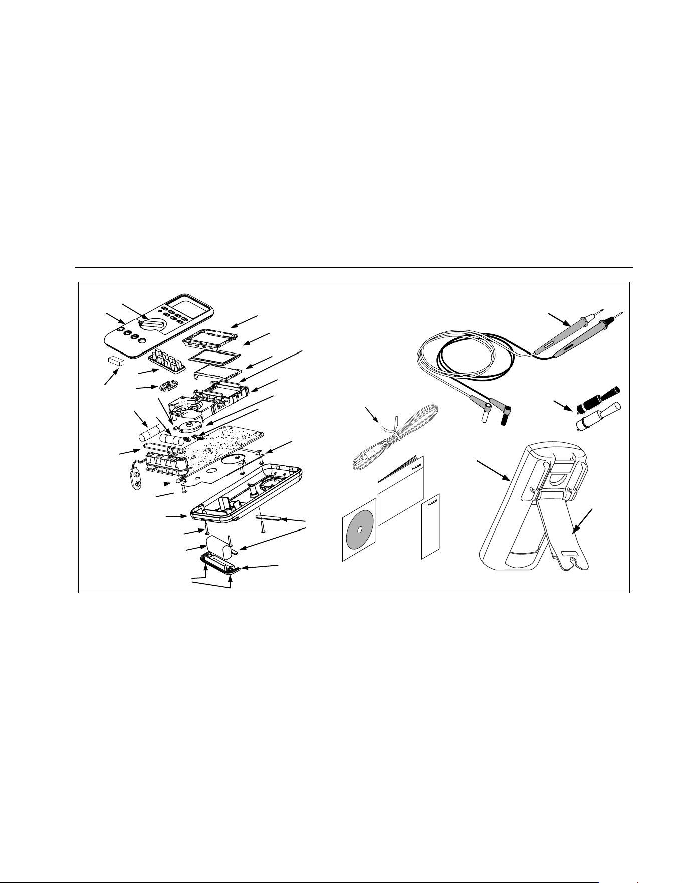
Service and Parts
If the Meter fails, check the battery and fuses. Review this
manual to verify proper use of the Meter.
Replacement parts and accessories are shown in Tables
8 and 9 and Figure 12.
To order parts and accessories, refer to “Contacting
Fluke”.
1.888.610.7664 sales@GlobalTestSupply.com
Fluke-Direct.com
80 Series V
Users Manual
38
F1
F2
1
aom12f.eps
Figure 11. Battery and Fuse Replacement
1.888.610.7664 sales@GlobalTestSupply.com
Fluke-Direct.com

Multimeters
Service and Parts
39
Table 8. Replacement Parts
Item Description Qty.
Fluke Part or Model
Number
BT1 Battery, 9 V 1
2139179
BT2 Cable Assy, 9 V Battery Snap 1 2064217
F1 W
Fuse, 0.440 A, 1000 V, FAST 1 943121
F2 W Fuse, 11 A, 1000 V, FAST 1 803293
H2-4 Screw, Case 3 832246
H5-9 Screw, Bottom Shield 5 448456
J1-2 Elastomeric Connector 2 817460
MP2 Shield, Top 1 2073906
MP4 Shield, Bottom 1 2074025
MP5 Case Top (PAD XFER) With Window 1 2073992
MP6 Case Bottom 1 2073871
MP8 Knob, Switch (PAD XFER) 1 2100482
MP9 Detent, Knob 1 822643
MP10-11 Foot, Non-Skid 2 824466
MP13 Shock Absorber 1 828541
MP14 O-Ring, Input Receptacle 1 831933
MP15 Holster 1 2074033
MP22 Battery Door 1 2073938
MP27-MP30 Contact RSOB 4 1567683
MP31 Mask, LCD (PAD XFER) 1 2073950
MP41 Housing, RSOB 1 2073945
W To ensure safety, use exact replacement only.
1.888.610.7664 sales@GlobalTestSupply.com
Fluke-Direct.com

80 Series V
Users Manual
40
Table 8. Replacement Parts (cont.)
Item Description Qty.
Fluke Part or Model
Number
AC72 Alligator Clip, Black 1 1670652
AC72 Alligator Clip, Red 1 1670641
TL75 Test Lead Set 1 855742
MP81 Thermocouple Assembly, K-Type, Beaded, Molded Dual Banana Plug, Coiled 1 1273113
MP390-391 Access Door Fastener 2 948609
NA Tiltstand 1 2074040
U5 LCD, 4.5 DIGIT,TN, Transflective, Bar Graph, OSPR80 1 2065213
CR6 Lightpipe 1 2074057
S2 Keypad 1 2105884
TM1 80 Series V Multi-Language Getting Started Manual 1 2101973
TM2 80 Series V Quick Reference Card 1 2101986
TM3 CD ROM,80 Series V User Manual 1 2101999
1.888.610.7664 sales@GlobalTestSupply.com
Fluke-Direct.com
Multimeters
Service and Parts
41
H2-4 (3)
BT1
MP390-391
MP6
MP22
MP10-11
MP5
Holster
MP15
Alligator Clips
TM3
TM2
TL75
Test Lead Set
Tilt Stand
MP8
TM1
W
F2
F1
MP14
S2
MP31
U5
CR6
MP2
MP4
MP81
MP9
MP41
J1-2
MP27-30
J3
H5-9 (5)
MP66
AC72
MP13
aom015c.eps
Figure 12. Replaceable Parts
1.888.610.7664 sales@GlobalTestSupply.com
Fluke-Direct.com

80 Series V
Users Manual
42
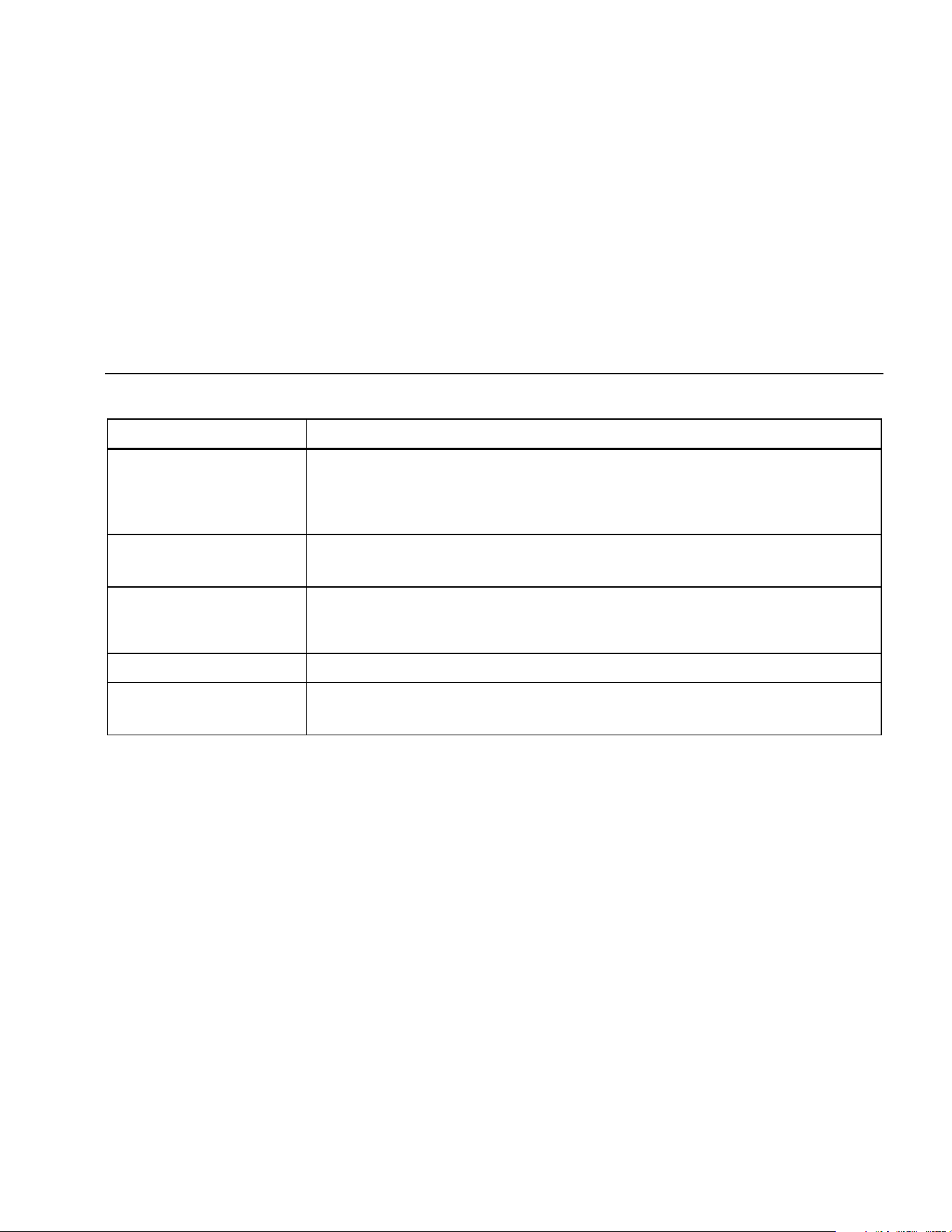
Table 9. Accessories
Item Description
AC72 Alligator Clips for use with TL75 test lead set
AC220 Safety Grip, Wide-Jaw Alligator Clips
TPAK ToolPak Magnetic Hanger
H87 Holster, Yellow
C25 Carrying Case, Soft
TL76 4 mm Diameter Test Leads
TL220 Industrial Test Lead Set
TL224 Test Lead Set, Heat-Resistant Silicone
TP1 Test Probes, Flat Blade, Slim Reach
TP4 Test Probes, 4 mm diameter, Slim Reach
Fluke accessories are available from an authorized Fluke distributor.
1.888.610.7664 sales@GlobalTestSupply.com
Fluke-Direct.com

Multimeters
Specifications
43
Specifications
Maximum Voltage between any Terminal and Earth Ground: 1000 V rms
W Fuse Protection for mA or μA inputs: 44/100 A, 1000 V FAST Fuse
W Fuse Protection for A input: 11 A, 1000 V FAST Fuse
Display: Digital: 6000 counts updates 4/sec; (Model 87 also has 19,999 counts in high-resolution mode).
Analog Bargraph: 33 segments, updates 40/sec. Frequency: 19,999 counts, updates 3/sec at >10 Hz
Temperature: Operating: -20 °C to +55 °C; Storage: -40 °C to +60 °C
Altitude: Operating: 2000 m; Storage: 10,000 m
Temperature Coefficient: 0.05 x (specified accuracy)/ °C (<18 °C or >28 °C)
Electromagnetic Compatibility:
In an RF field of 3 V/m total accuracy = specified accuracy + 20 counts
Except: 600 μA dc range total accuracy=specified accuracy +60 counts.
Temperature not specified.
Relative Humidity: 0 % to 90 % (0 °C to 35 °C); 0 % to 70 % (35 °C to 55 °C)
Battery Type: 9 V zinc, NEDA 1604 or 6F22 or 006P
Battery Life: 400 hrs typical with alkaline (with backlight off)
Vibration: Per MIL-PRF-28800 for a Class 2 instrument
Shock: 1 Meter drop per IEC 61010-1:2001
Size (HxWxL): 1.25 in x 3.41 in x 7.35 in (3.1 cm x 8.6 cm x 18.6 cm)
Size with Holster and Flex-Stand: 2.06 in x 3.86 in x 7.93 in (5.2 cm x 9.8 cm x 20.1 cm)
Weight: 12.5 oz (355 g)
Weight with Holster and Flex-Stand: 22.0 oz (624 g)
Safety: Complies with ANSI/ISA S82.01-2004, CSA 22.2 No. 1010.1:2004 to 1000 V Overvoltage Category III, IEC 664 to 600 V
Overvoltage Category IV. UL listed to UL61010-1. Licensed by TÜV to EN61010-1.
IP Rating: 30
1.888.610.7664 sales@GlobalTestSupply.com
Fluke-Direct.com
80 Series V
Users Manual
44
Detailed Specifications
For all detailed specifications:
Accuracy is given as ±([% of reading] + [number of least significant digits]) at 18° C to 28° C, with relative humidity up to
90 %, for a period of one year after calibration.
For Model 87 in the 4 ½-digit mode, multiply the number of least significant digits (counts) by 10. AC conversions are ac-
coupled and valid from 3 % to 100 % of range. Model 87 is true rms responding. AC crest factor can be up to 3 at full scale, 6
at half scale. For non-sinusoidal wave forms add -(2 % Rdg + 2 % full scale) typical, for a crest factor up to 3.
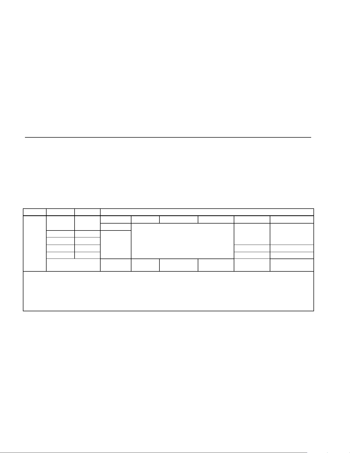
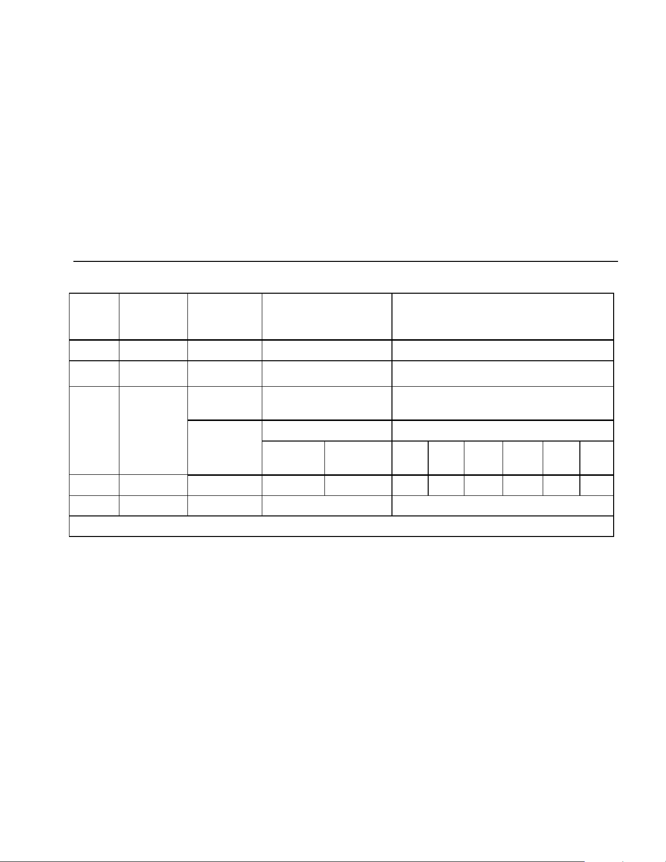
Table 10. Model 87 AC Voltage Function Specifications
Function Range Resolution Accuracy
45 – 65 Hz 30 – 200 Hz 200 – 440 Hz 440 Hz - 1 kHz 1 - 5 kHz 5 - 20 kHz
[1]
600.0 mV 0.1 mV
± (0.7 % + 4)
6.000 V 0.001 V
60.00 V 0.01 V
± (2.0 % + 4) ± (2.0 % + 20)
600.0 V 0.1 V
± (2.0 % + 4)
[3]
unspecified
1000 V 1 V
± (0.7 % + 2)
± (1.0 % + 4)
unspecified unspecified
K
[2,4]
Low pass filter
Same as
45-65 Hz
± (1.0 % + 4)
+1 % + 4
-6 % - 4
[5]
unspecified unspecified unspecified
[1] Below 10 % of range, add 12 counts.
[2] The Meter is a true rms responding meter. When the input leads are shorted together in the ac functions, the Meter may display a residual reading between
1 and 30 counts. A 30 count residual reading will cause only a 2-digit change for readings over 3 % of range. Using REL to offset this reading may produce
a much larger constant error in later measurements.
[3] Frequency range: 1 kHz to 2.5 kHz.
[4] A residual reading of up to 13 digits with leads shorted, will not affect stated accuracy above 3 % of range.
[5] Specification increases from -1% at 200 Hz to -6% at 440 Hz when filter is in use.
1.888.610.7664 sales@GlobalTestSupply.com
Fluke-Direct.com
Multimeters
Specifications
45
Table 11. Model 83 AC Voltage Function Specifications
Function Range Resolution Accuracy
50 Hz - 60 Hz 30 Hz - 1 kHz 1 kHz - 5 kHz
K
1
600.0 mV
6.000 V
60.00 V
600.0 V
1000 V
0.1 mV
0.001 V
0.01 V
0.1 V
1 V
± (0.5 % + 4)
± (0.5 % + 2)
± (0.5 % + 2)
± (0.5 % + 2)
± (0.5 % + 2)
± (1.0 % + 4)
± (1.0 % + 4)
± (1.0 % + 4)
± (1.0 % + 4)
± (1.0 % + 4)
± (2.0 % + 4)
± (2.0 % + 4)
± (2.0 % + 4)
± (2.0 % + 4)
2
unspecified
1. Below a reading of 200 counts, add 10 counts.
2. Frequency range: 1 kHz to 2.5 kHz.
1.888.610.7664 sales@GlobalTestSupply.com
Fluke-Direct.com
80 Series V
Users Manual
46
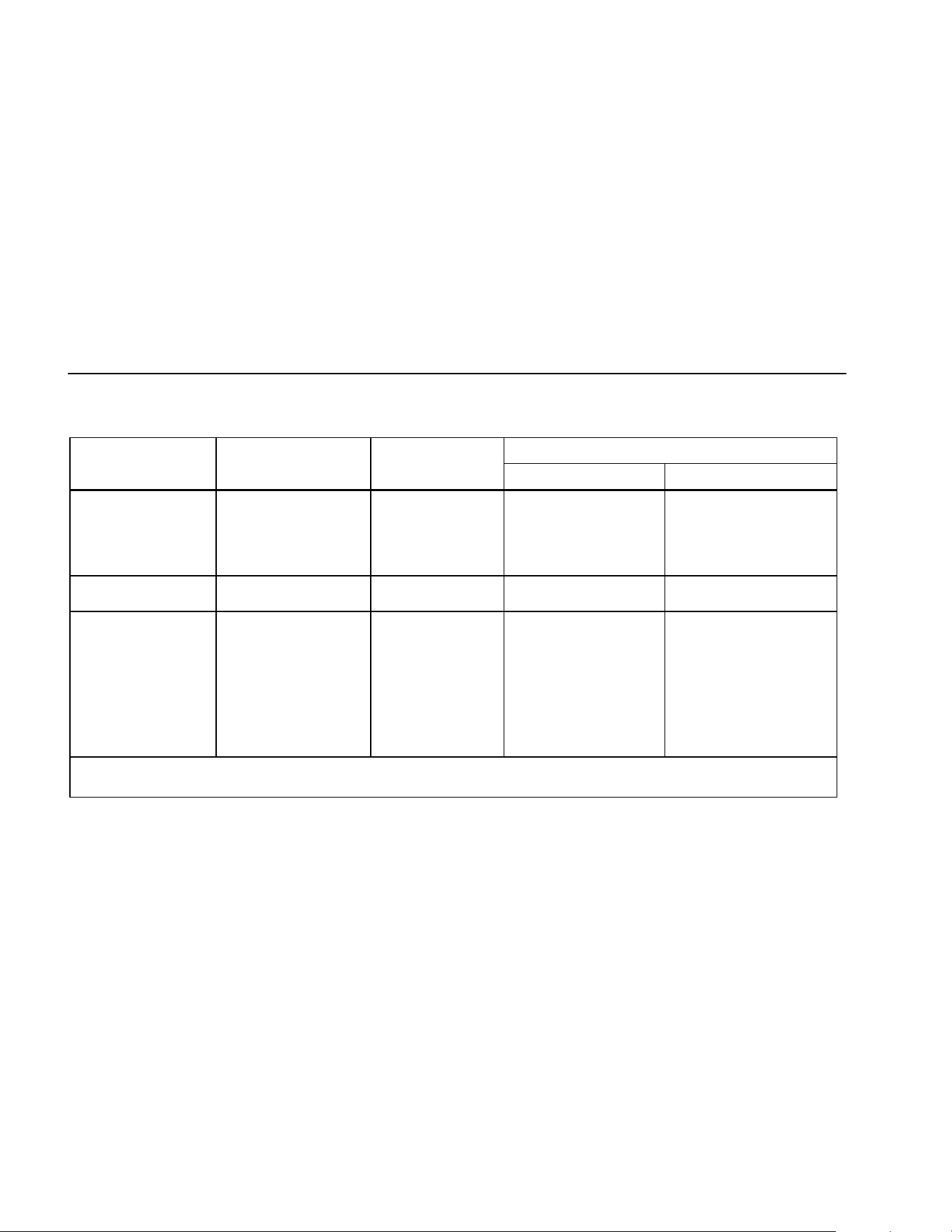
Table 12. DC Voltage, Resistance, and Conductance Function Specifications
Accuracy
Function Range Resolution
Model 83 Model 87
L
6.000 V
60.00 V
600.0 V
1000 V
0.001 V
0.01 V
0.1 V
1 V
± (0.1 % + 1)
± (0.1 % + 1)
± (0.1 % + 1)
± (0.1 % + 1)
± (0.05 % + 1)
± (0.05 % + 1)
± (0.05 % + 1)
± (0.05 % + 1)
F
mV
600.0 mV 0.1 mV ± (0.3 % + 1) ± (0.1 % + 1)
e
nS
600.0 Ω
6.000 kΩ
60.00 kΩ
600.0 kΩ
6.000 MΩ
50.00 MΩ
60.00 nS
0.1 Ω
0.001 kΩ
0.01 kΩ
0.1 kΩ
0.001 MΩ
0.01 MΩ
0.01 nS
± (0.4 % + 2)
1
± (0.4 % + 1)
± (0.4 % + 1)
± (0.7 % + 1)
± (0.7 % + 1)
± (1.0 % + 3)
2
± (1.0 % + 10)
1
± (0.2 % + 2)
1
± (0.2 % + 1)
± (0.2 % + 1)
± (0.6 % + 1)
± (0.6 % + 1)
± (1.0 % + 3)
2
± (1.0 % + 10)
1
1. When using the REL Δ function to compensate for offsets.
2. Add 0.5 % of reading when measuring above 30 MΩ in the 50 MΩ range, and 20 counts below 33 nS in the 60 nS range.
1.888.610.7664 sales@GlobalTestSupply.com
Fluke-Direct.com
Multimeters
Specifications
47
Table 13. Temperature Specifications (87 Only)
Temperature Resolution Accuracy
1,2
-200 °C to +1090 °C
-328 °F to +1994 °F
0.1 °C
0.1 °F
1 % + 10
1 % + 18
1. Does not include error of the thermocouple probe.
2. Accuracy specification assumes ambient temperature stable to
±1 °C. For ambient temperature changes of ±5 °C, rated accuracy
applies after 1 hour.
1.888.610.7664 sales@GlobalTestSupply.com
Fluke-Direct.com
80 Series V
Users Manual
48
Table 14. Current Function Specifications
Accuracy
Function Range Resolution
Model 83
1
Model 87
2, 3
Burden Voltage
(typical)
mA
\
(45 Hz to 2 kHz)
mA
[
60.00 mA
400.0 mA
6
6.000 A
10.00 A
4
60.00 mA
400.0 mA
6
6.000 A
10.00 A
4
0.01 mA
0.1 mA
0.001 A
0.01 A
0.01 mA
0.1 mA
0.001 A
0.01 A
± (1.2 % + 2)
5
± (1.2 % + 2)
5
± (1.2 % + 2)
5
± (1.2 % + 2)
5
± (0.4 % + 4)
± (0.4 % + 2)
± (0.4 % + 4)
± (0.4 % + 2)
± (1.0 % + 2)
± (1.0 % + 2)
± (1.0 % + 2)
± (1.0 % + 2)
± (0.2 % + 4)
± (0.2 % + 2)
± (0.2 % + 4)
± (0.2 % + 2)
1.8 mV/mA
1.8 mV/mA
0.03 V/A
0.03 V/A
1.8 mV/mA
1.8 mV/mA
0.03 V/A
0.03 V/A
μA B
(45 Hz to 2 kHz)
μAF
600.0 μA
6000 μA
600.0 μA
6000 μA
0.1 μA
1 μA
0.1 μA
1 μA
± (1.2 % + 2)
5
± (1.2 % + 2)
5
± (0.4 % + 4)
± (0.4 % + 2)
± (1.0 % + 2)
± (1.0 % + 2)
± (0.2 % + 4)
± (0.2 % + 2)
100 μV/μA
100 μV/μA
100 μV/μA
100 μV/μA
1. AC conversion for Model 83 is ac coupled and calibrated to the rms value of a sine wave input.
2. AC conversions for Model 87 are ac coupled, true rms responding, and valid from 3 % to 100 % of range, except 400 mA range (5 %
to 100 % of range) and 10 A range (15 % to 100 % or range).
3. Model 87 is a true rms responding meter. When the input leads are shorted together in the ac functions, the Meter may display a
residual reading between 1 and 30 counts. A 30 count residual reading will cause only a 2 digit change for readings over 3 % of
range. Using REL to offset this reading may produce a much larger constant error in later measurements
4. W 10 A continuous up to 35 °C; < 20 minutes on, 5 minutes off at 35 °C to 55 °C. 20 A for 30 seconds maximum; > 10 A unspecified.
5. Below a reading of 200 counts, add 10 counts.
6. 400 mA continuous; 600 mA for 18 hrs maximum.
1.888.610.7664 sales@GlobalTestSupply.com
Fluke-Direct.com
Multimeters
Specifications
49
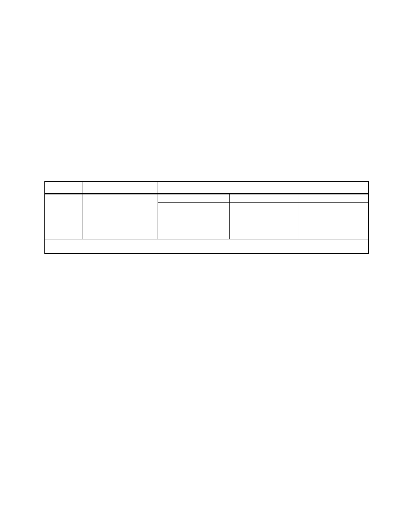
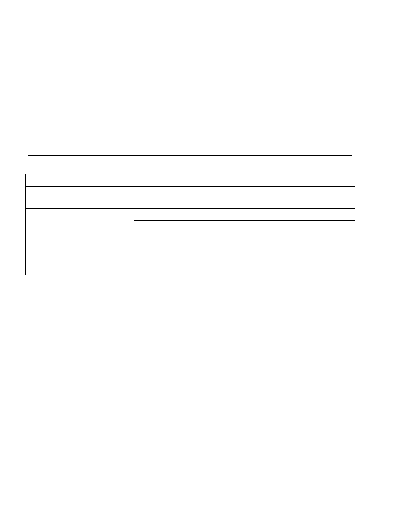
Table 15. Capacitance and Diode Function Specifications
Function Range Resolution Accuracy
E 10.00 nF
100.0 nF
1.000 μF
10.00 μF
100.0 μF
9999 μF
0.01 nF
0.1 nF
0.001 μF
0.01 μF
0.1 μF
1 μF
± (1 % + 2)
1
± (1 % + 2)
1
± (1 % + 2)
± (1 % + 2)
± (1 % + 2)
± (1 % + 2)
G 3.000 V 0.001 V ± (2 % + 1)
1. With a film capacitor or better, using Relative mode to zero residual.
Table 16. Frequency Counter Specifications
Function Range Resolution Accuracy
Frequency
(0.5 Hz to 200 kHz,
pulse width > 2 μs)
199.99
1999.9
19.999 kHz
199.99 kHz
> 200 kHz
0.01 Hz
0.1 Hz
0.001 kHz
0.01 kHz
0.1 kHz
± (0.005 % + 1)
± (0.005 % + 1)
± (0.005 % + 1)
± (0.005 % + 1)
unspecified
1.888.610.7664 sales@GlobalTestSupply.com
Fluke-Direct.com
80 Series V
Users Manual
50
Table 17. Frequency Counter Sensitivity and Trigger Levels
Minimum Sensitivity (RMS Sine wave)
Input Range
1
5 Hz - 20 kHz 0.5 Hz - 200 kHz
Approximate Trigger Level
(DC Voltage Function)
600 mV dc
600 mV ac
6 V
60 V
600 V
1000 V
70 mV (to 400 Hz)
150 mV
0.3 V
3 V
30 V
100 V
70 mV (to 400 Hz)
150 mV
0.7 V
7 V (≤140 kHz)
70 V (≤14.0 kHz)
200 V (≤1.4 kHz)
40 mV
⎯
1.7 V
4 V
40 V
100 V
Duty Cycle Range Accuracy
0.0 to 99.9 % Within ± (0.2% per kHz + 0.1 %) for rise times < 1 μs.
1. Maximum input for specified accuracy = 10X Range or 1000 V.
1.888.610.7664 sales@GlobalTestSupply.com
Fluke-Direct.com
Multimeters
Specifications
51
Table 18. Electrical Characteristics of the Terminals
Function
Overload
Protection
1
Input
Impedance
(nominal)
Common Mode
Rejection Ratio
(1 kΩ unbalance)
Normal Mode Rejection
L 1000 V rms 10 MΩ < 100 pF > 120 dB at dc, 50 Hz or 60 Hz > 60 dB at 50 Hz or 60 Hz
F
mV
1000 V rms 10 MΩ < 100 pF > 120 dB at dc, 50 Hz or 60 Hz > 60 dB at 50 Hz or 60 Hz
K 1000 V rms 10 MΩ < 100 pF
(ac-coupled)
> 60 dB, dc to 60 Hz
Open Circuit
Full Scale Voltage Typical Short Circuit Current
Test Voltage
To 6.0 MΩ 50 MΩ or
60 nS
600 Ω 6 k 60 k 600 k 6 M 50 M
e 1000 V rms < 7.9 V dc < 4.1 V dc < 4.5 V dc 1 mA 100 μA 10 μA 1μA 1 μA 0.5 μA
G 1000 V rms < 7.9 V dc 3.000 V dc 1.0 mA typical
1. 10
6
V Hz max
1.888.610.7664 sales@GlobalTestSupply.com
Fluke-Direct.com
80 Series V
Users Manual
52
Table 19. MIN MAX Recording Specifications
Model Nominal Response Accuracy
83 100 ms to 80 % Specified accuracy ± 12 counts for changes > 200 ms in duration
(± 40 counts in ac with beeper on)
100 ms to 80 % (dc functions) Specified accuracy ± 12 counts for changes > 200 ms in duration
120 ms to 80 % (ac functions) Specified accuracy ± 40 counts for changes > 350 ms and inputs > 25 % of range
87
250 μs (peak) (Model 87 only)
1
Specified accuracy ± 100 counts for changes > 250 μs in duration
(add ± 100 counts for readings over 6000 counts)
(add ± 100 counts for readings in Low Pass mode)
1. For repetitive peaks: 1 ms for single events.
1.888.610.7664 sales@GlobalTestSupply.com
Fluke-Direct.com