
283 FC
True-RMS 1500 V Multimeter
Users Manual
7/2024 (English)
©2024 Fluke Corporation. All rights reserved.
Specifications are subject to change without notice.
All product names are trademarks of their respective companies.
1.888.610.7664 sales@GlobalTestSupply.com
Fluke-Direct
.com

Lifetime Limited Warranty
Each Fluke 20, 70, 80, 170, 180 and 280 Series DMM will be free from defects in material and
workmanship for its l ifetime. As used herein, “l ifetime” is defined as seven years after Fluke d iscontinues
manufacturing the product, but the warranty period shall be at least ten years from the date of purchase.
This warranty does not cover fuses, d isposable batteries, damage from neglect, misuse, contamination,
al teration, accident or abnormal cond itions of operation or hand l ing, includ ing failures caused by use
outside of the product’s specifications, or normal wear and tear of mechanical components. This
warranty covers the original purchaser onl y and is not transferable.
For ten years from the date of purchase, this warranty also covers the LCD. Thereafter, for the l ifetime of
the DMM, Fluke will replace the LCD for a fee based on then current component acquisition costs.
To establ ish original ownership and prove date of purchase, please complete and return the registration
card accompanying the product. Fluke will, at its option, repair at no charge, replace or refund the
purchase price of a defective product purchased through a Fluke authorized sales outlet and at the appl
icable international price. Fluke reserves the right to charge for importation costs of repair/replacement
parts if the product purchased in one country is sent for repair elsewhere.
If the product is defective, contact your nearest Fluke authorized service center to obtain return
authorization information, then send the product to that service center, with a description of the d ifficul
ty, postage and insurance prepaid (FOB Destination). Fluke assumes no risk for damage in transit. Fluke
will pay return transportation for product repaired or replaced in-warranty. Before making any non-
warranty repair, Fluke will estimate cost and obtain authorization, then invoice you for repair and return
transportation.
THIS WARRANTY IS YOUR ONLY REMEDY. NO OTHER WARRANTIES, SUCH AS FITNESS FOR A
PARTICULAR PURPOSE, ARE EXPRESSED OR IMPLIED. FLUKE SHALL NOT BE LIABLE FOR ANY
SPECIAL, INDIRECT, INCIDENTAL OR CONSEQUENTIAL DAMAGES OR LOSSES, INCLUDING
LOSS OF DATA, ARISING FROM ANY CAUSE OR THEORY. AUTHORIZED RESELLERS ARE NOT
AUTHORIZED TO EXTEND ANY DIFFERENT WARRANTY ON FLUKE’S BEHALF. Since some states
do not allow the exclusion or limitation of an implied warranty or of incidental or consequential
damages, this limitation of liability may not apply to you. If any provision of this warranty is held
invalid or unenforceable by a court or other decision-maker of competent jurisdiction, such
holding will not affect the validity or enforceability of any other provision.
1.888.610.7664 sales@GlobalTestSupply.com
Fluke-Direct
.com

i
Table of Contents
Title Page
Introduction................................................................................................................................... 1
Contact Fluke Corporation...................................................................................................... 1
Safety Information...................................................................................................................... 1
Hazardous Voltage..................................................................................................................... 1
Features.......................................................................................................................................... 2
Auto Sleep Mode................................................................................................................ 2
Wireless Radio..................................................................................................................... 2
Radio Frequency Data...................................................................................................... 2
MIN MAX AVG Record Mode ......................................................................................... 3
Relative Mode...................................................................................................................... 4
Display Hold ......................................................................................................................... 4
Auto Hold Mode..................................................................................................................4
Yellow Button....................................................................................................................... 5
Data Log ................................................................................................................................ 5
Display Backlight ................................................................................................................ 5
Manual and Auto Range................................................................................................... 5
Limit Gauge........................................................................................................................... 6
Setup Menu ................................................................................................................................... 7
Log........................................................................................................................................... 8
Beeper and Alert................................................................................................................. 8
Clamp...................................................................................................................................... 9
Auto Backlight Timeout ................................................................................................... 9
Date/Time.............................................................................................................................. 9
Auto Sleep ............................................................................................................................ 10
Device Information ............................................................................................................ 10
Calibration Cycle ................................................................................................................ 10
Functions ....................................................................................................................................... 10
Display.................................................................................................................................... 11
Control Knob........................................................................................................................ 12
Pushbuttons......................................................................................................................... 13
Self Check............................................................................................................................. 15
Inputs ...................................................................................................................................... 16
AC Low Value Input Behavior of True-RMS Meters .............................................. 16
Wireless Radio Setup........................................................................................................ 16
Pair with Fluke Connect App ................................................................................. 17
Pair with a283 FC Current Clamp ........................................................................ 17
1.888.610.7664 sales@GlobalTestSupply.com
Fluke-Direct
.com

ii
283 FC
Users Manual
Basic Measurements ................................................................................................................. 18
AC and DC Voltage ............................................................................................................ 19
AC or DC Current with a283 FC Current Clamp...................................................... 20
AC VA and DC Power ........................................................................................................ 20
Resistance Measurements............................................................................................. 21
Capacitance Measurements.......................................................................................... 22
Continuity Test .................................................................................................................... 23
Frequency Measurement ................................................................................................ 24
Firmware Update ......................................................................................................................... 25
Firmware Version ........................................................................................................................ 25
Maintenance.................................................................................................................................. 25
General Maintenance........................................................................................................ 26
Product Disposal ................................................................................................................26
Battery Replacement ........................................................................................................ 26
Test Lead Storage.............................................................................................................. 28
Service and Parts ........................................................................................................................ 29
Specifications............................................................................................................................... 30
General Specifications ..................................................................................................... 30
Detailed Specifications .................................................................................................... 30
1.888.610.7664 sales@GlobalTestSupply.com
Fluke-Direct
.com

1
Introduction
XW Warning
To prevent possible electrical shock, fire, or personal injury, read all safety
information before you use the Product.
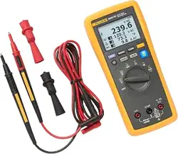
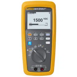
The 283 FC True-RMS 1500 V Multimeter (the Meter or Product) is a True-RMS Digital
Multimeter.
Safety Information
A Warning identifies hazardous conditions and procedures that are dangerous to the user.
A Caution identifies conditions and pro
cedures that can cause damage to the Product or
the equipment under test.
Hazardous Voltage
The hazardous voltage warning [ shows on the display when the Product detects a voltage
≥30 V or voltage overload (OL).
1.888.610.7664 sales@GlobalTestSupply.com
Fluke-Direct
.com

283 FC
Users Manual
2
Features
This section has descriptions of all the features in the Meter.
Auto Sleep Mode
To save battery power, the Meter goes to the Sleep Mode if there is no function change or
button pushed for a set period of time:
5 Minutes
30 Minutes
45 Minutes
60 Minutes
Never
When the Meter is in the Sleep Mode, turn the Control Knob to any position (except OFF), push
any button, or use the FC App to wake up the Meter. This setting is persistent and remains set
when you turn off the Meter. See Setup Menu to adjust the setting.
Note
When you use the FC app, log, min/max, auto hold, and calibration functions, Sleep
Mode is disabled.
Wireless Radio
The Product uses low-power wireless radio technology to send or receive measurements to
other wireless test tools or the Fluke Connect® app on a mobile device such as a smartphone
or tablet. You can set up to pair with:
A mobile device. Use the Fluke Connect app to view measurements remotely, save to
Flu
ke Cloud™ storage, and share the information with your team.
a283 FC Wireless AC/DC Clamp to show the Clamp measurements on the Meter display.
The wireless radio does not cause interference with meter measurements.
See Wireless Radio Setup for instructions on how to set up and use the wireless radio in the
Product.
Radio Frequency Data
Changes o
r modifications to the wireless 2.4 GHz radio not expressly approved by Fluke
Corporation could void the user’s authority to operate the equipment.
1.888.610.7664 sales@GlobalTestSupply.com
Fluke-Direct
.com

True-RMS 1500 V Multimeter
Features
3
MIN MAX AVG Record Mode
The MIN MAX AVG record mode records the minimum and maximum input values, and
calculates a running average of all measurements during the recording session for the full
function of the single display or dual display. The Product beeps when a new minimum or
maximum is sensed.
Note
For dc functions, accuracy is the specified accuracy of the measurement function,
±12 counts for changes longer than 350 ms in duration.
For ac functions, accuracy is the specified accuracy of the measurement function
±40 counts for changes longer than 900 ms in duration.
To start a MIN MAX AVG recording session:
1. Make sure the Product is set to the correct measurement function and on the correct
range.
Autorange and manual range selection are disabled while MIN MAX AVG is active.
2. Push
P. and MAX show at the top of the display. The measurement that shows
on the display is the maximum value measured. It changes only when a new maximum
value is sensed.
3. To pause MIN MAX AVG record, push
M. h shows on the display while record is
paused.
Recorded values are not deleted. To continue the record session, push
M.
4. To exit and erase the MIN, MAX, and AVG values, push
P for >2 seconds or turn the rotary
switch.
5. To see the other recorded values (minimum and average), push
P. Each push of the
button rotates through the maximum, minimum, average, and live values. The value on the
display is identified with a MAX, MIN, or AVG label below the icon. No label below
icon indicates that the live measurement shows on the display.
Note
Auto Sleep mode is disabled in MIN MAX AVG record mode.
1.888.610.7664 sales@GlobalTestSupply.com
Fluke-Direct
.com

283 FC
Users Manual
4
Relative Mode
In Relative Mode, the Meter will zero the display and store the present reading as the
reference for subsequent measurements. The Meter is locked into the selected manual range
when you pushed
R.
The reading shown is always the difference between the present reading and the stored
reference value. For example, if the stored reference value is 15.00 V and the live reading is
14.10 V, the display shows -0.90 V (delta).
The measurements show on the display in this order:
Delta
Reference
Live
Push
R again to exit the Relative Mode.
Display Hold
XW Warning
To prevent possible electrical shock, fire, or personal injury, do not use the
HOLD function to measure unknown potentials. When HOLD is turned on, the
display does not change when a different potential is measured.
In the Display Hold Mode, the Product captures the live reading on the display and does not
update until you exit the Display Hold Mode. To hold a measurement on the display, push
M.
The display shows h when Display Hold is turned on.
Push
M again to exit Display Hold Mode and show live measurements on the display.
Auto Hold Mode
The Auto Hold Mode captures the present reading on the display. When a new, stable reading
is detected, the Meter beeps and displays the new reading. To enter or exit the Auto Hold
Mode, push
M >2 s.
For V ac, V dc, VA, A ac, A dc, and resistance functions, the threshold is 1% of range and the
fluctuation is 0.2 % of range.
For the capacitance function, the threshold is 5 % of range and the fluctuation is 1 % of range.
Auto Hold Mode for mV ac and mV dc functions is disabled.
Auto Hold Mode triggers when the measured value is greater than the threshold and the
measured value is fluctuating within the fluctuation range and >2 s.
1.888.610.7664 sales@GlobalTestSupply.com
Fluke-Direct
.com

True-RMS 1500 V Multimeter
Features
5
Yellow Button
Push the yellow button (N) to set the Product to a different measurement function. The
different functions are shown in yellow around the rotary switch. Frequency, VA, mV ac,
capacitance, and A ac with the optional a283 FC Clamp are functions of the Product set with
the yellow button.
Data Log
Push O >2 s. to enter the Data Log mode.
See Setup Menu to adjust the log interval and duration time.
Display Backlight
Push O:
1x to turn on the display backlight
2x to illuminate the keypad
3x to turn off the backlight and the keypad
By default, the backlight automatically turns off after 2 minutes. See Setup Menu to change
the time interval.
Manual and Auto Range
The Product can be set to manual or auto range. In auto range, the Product sets the range so
the input is shown with the best resolution. Manual range lets you set the range.
When you turn on the Product, it is set to auto range.
To set a manual range:
1. Push
S to go to manual range.
2. Push
S again to cycle though the available manual ranges of 6 V, 60 V, 600 V, 1000 V.
The display shows the selected manual range in the upper left corner.
3. To exit manual range, push
S >2 s.
The display shows the auto range in the upper left corner.
Note
You cannot change range when the Product is in the MIN MAX AVG record mode or in
Display Hold mode. If you push
S in one of these modes, the Product beeps twice to
alert you to an invalid operation.
1.888.610.7664 sales@GlobalTestSupply.com
Fluke-Direct
.com
283 FC
Users Manual
6
Limit Gauge
For high-volume and repetitive measurements of V ac, V dc, mV ac, mV dc, A dc, and A ac ,
you can use the Limit Gauge to monitor the measurements. After setup, a visual gauge shows
on the display with the set range and where the present measurement is in that range. Any
measurement outside a set percentage or range causes an audible and visible alarm.
Note
The measurement range is set to auto range when in the limit gauge function.
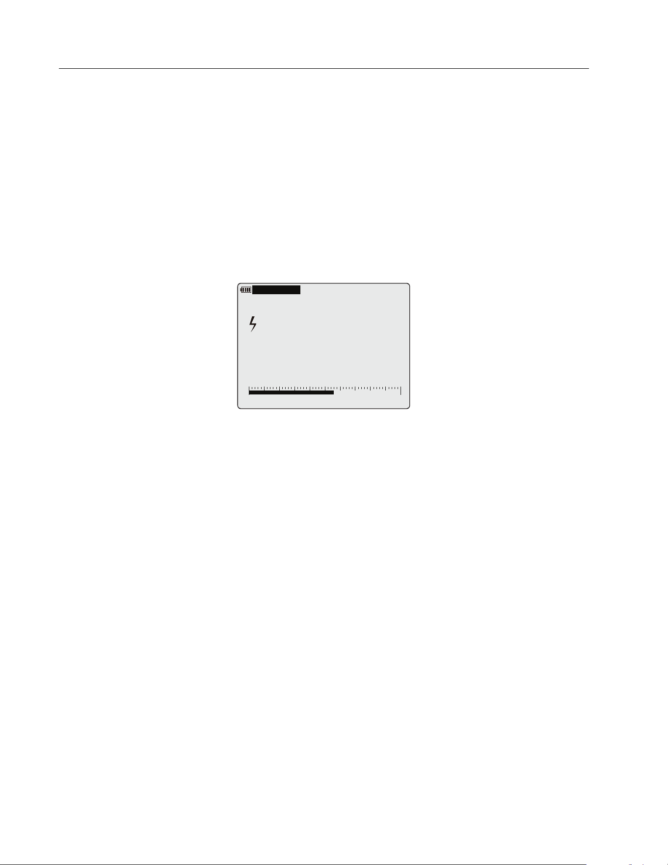
As an example, in the V ac mode, set the limit gauge by digit to the range of 180 V to 250 V
and apply an input signal of 220 V/50 Hz. See Figure 1.
Figure 1. Limit Gauge
The Limit Gauge has setup options:
Option 1. set the expected value and acceptable deviation percentage. For example, 1000 V
and a ±10 % has an acceptable range of 900 V to 1100 V. Any measurement above or below
the set value causes an audible and visible alarm.
Option 2. Set a manual range. For example, set 900 V to 1100 V as acceptable range. Any
measurement above or below the range causes an audible and visible alarm.
Option 3. Select a previous setup. Use this option for often-used setups or recurring site
inspections.
To set up a gauge:
1. Push
T to open the Limit Gauge menu.
2. Use
to highlight New Settings.
3. Push OK to open the New Setting menu.
4. Use
to highlight the type of gauge, either By Digit or By Percentage.
5. Push OK to open the Adjustment menu.
6. Use
to select a digit and to change a digit.
7. Push OK to save the setting in the Previous Setting list.
A
uto Range 6
00
V
04/12/24 04:15
L
O
WER
U
PPER
180 250
219.6
VAC
1.888.610.7664 sales@GlobalTestSupply.com
Fluke-Direct
.com

True-RMS 1500 V Multimeter
Setup Menu
7
To use a saved setting:
1. Push
T to open the Limit Gauge menu.
2. Use
to highlight Previous Settings.
3. Push OK to open the Previous Setting menu.
4. Use
to select the gauge to use.
5. Push OK to go back to the Limit Gauge menu.
The selected Limit Gauge is enabled.
6. Push Back to exit the Limit Gauge menu and use the Limit Gauge.
To disable the gauge:
1. Push
T to open the Limit Gauge menu.
2. Use
to highlight Disable Limit Gauge.
3. Push OK.
4. Push Back to exit the Limit Gauge menu and resume measurements without the Limit
Gauge.
For a quick on/off, push
T >2 s to enable the last gauge setting that was used.
Setup Menu
The Meter has a Setup menu to access the adjustable features:
Log
Beeper and Alert
Clamp
Auto Backlight Timeout
Date/Time
Auto Sleep
Device Information
Calibration Cycle
1.888.610.7664 sales@GlobalTestSupply.com
Fluke-Direct
.com

283 FC
Users Manual
8
To access the menu:
1. Push
U to open the Setup menu.
In the menu,
and buttons are active.
2. Use
to highlight and change the selection.
3. Push OK to set the change.
4. Push BACK to exit a menu.
Log
In the Log menu, you can set the log duration and interval, see how much memory is used, and
clear the log memory.
Note
When the log duration is set to 0 days, 0 minutes, and 0 sec, the Meter continuously
logs until you manually stop the log function or the memory is full.
Beeper and Alert
In the Beeper and Alert menu, set the beeper to on or off when you push any button.
You can also set the audible and visible warning on or off when the polarity feature is
triggered. The Meter checks the polarity during a dc voltage measurement. When dc voltage
is less than -10 V:
Red LED blinks
Beeper sounds
blinks on the display
To disable the red LED and beeper when polarity is triggered, set to off.
The limit gauge has an audible and visible warning when the live reading is outside of the limit
gauge range:
Red LED blinks
Beeper sounds
LOWER or UPPER limit highlighted
To disable the red LED and beeper when limit gauge is triggered, set to off. For more
information, see Limit Gauge.
1.888.610.7664 sales@GlobalTestSupply.com
Fluke-Direct
.com

True-RMS 1500 V Multimeter
Setup Menu
9
Clamp
At the first use of the Meter with a Clamp, the Meter can search for Clamps within range that
are turned on.
When found, the Meter shows the Clamp serial number (maximum 5 clamps) in a list:
1. Use
to select the Clamp to pair with the Meter.
When a Clamp is paired with the Meter, the displays shows the clamp icon in upper right
corner.
2. Use Disconnect to temporarily unpair the Clamp.
When the control knob changes or the Meter power is turned on, the Clamp automatically
pairs again.
3. Use Clear to permanently unpair the Clamp.
When the Meter power is turned on, you must pair the Clamp again.
Auto Backlight Timeout
In the Auto Backlight Timeout menu, you can set a duration for how long the display backlight
and keypad backlight stay on as:
2 minutes
15 minutes
30 minutes
Never
Date/Time
In the Date/Time menu, adjust the date and time. You can also select the date format as:
DD/MM/YYYY
MM/DD/YYYY
YYYY/MM/DD
1.888.610.7664 sales@GlobalTestSupply.com
Fluke-Direct
.com

283 FC
Users Manual
10
Auto Sleep
In the Auto Sleep menu, set the time lapse for when the Meter goes to the Sleep Mode as:
5 mins
30 mins
45 mins
60 mins
Never
Device Information
The Device Information menu has details about:
Model
Serial number
Firmware version
Calibration Date
TTBLE version
FBLE Version
Calibration Cycle
In the Calibration Cycle menu, set the cycle to:
1 year
2 years
3 years
Never
Functions
This section has descriptions of all the functions in the Meter.
1.888.610.7664 sales@GlobalTestSupply.com
Fluke-Direct
.com
True-RMS 1500 V Multimeter
Functions
11
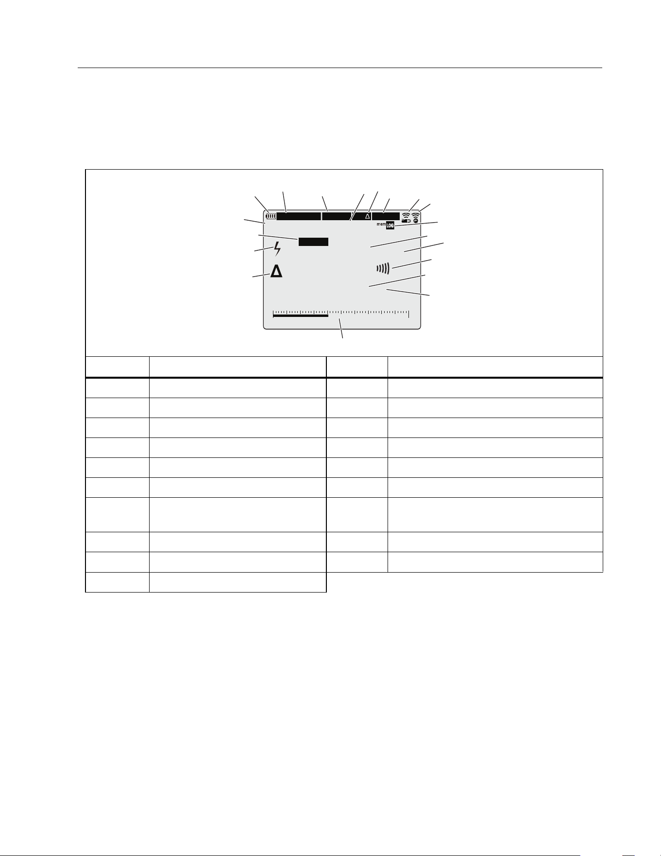
Display
The display is large and bright to show all information on the screen. This display is for indoor
and outdoor use. Table 1 is a list of all the functions on the display.
Table 1. Display
Item Function Item Function
A
Battery status
K
Unit and function of measurement
B
Date/Time
L
Continuity
C
MIN/MAX Mode is on
M
Live measurement
D
Active MIN/MAX selection
N
Unit of and function measurement
E
Relative Mode is on
O
Limit Gauge indicator
F
HOLD/AutoHold Mode is on
P
Relative Mode measurement
G
Clamp paired
Q
Voltage >30 V
or voltage overload (OL)
H
FC Connect is on
R
Polarity Mode is triggered
I
Logging Mode/Memory usage
S
Auto/Manual Range
J
Live measurement
M
anual Range 60V
04/12/24 04:15
MIN/MAX
MIN
POLARITY
AutoHOLD
REL
L
O
WER
U
PPE
R
12 20
-15.45
VDC
10.20
AAC
A
B
C
E
G
H
J
L
N
O
P
M
Q
R
S
D
F
K
0%
I
1.888.610.7664 sales@GlobalTestSupply.com
Fluke-Direct
.com
283 FC
Users Manual
12
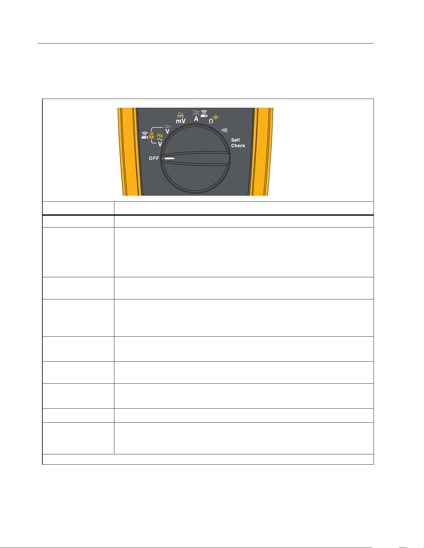
Control Knob
Table 2 is a list of the Control Knob functions.
Table 2. Control Knob Positions
Position Function
OFF Turn off the Product.
E
AC voltage measurement from 60.0 mV to 1000 V.
Push
N to measure frequency from 2 Hz to 99.99 kHz.
Push
N again to measure VAC + AAC.
Push
N again to measure VA + AAC.
A
Connect with a283 FC Clamp to measure dc power (VA) or ac VA. See
Wireless Radio.
4
DC voltage from 1 mV to 1500 V.
Push
N again to measure VDC + ADC.
Push
N again to measure VA + ADC.
D
DC voltage measurements from 0.1 mV to 600 mV.
Push
N to measure ac voltage from 6 mV to 600 mV.
C
B
Connect with a283 FC Clamp to measure ac or dc current ≤60 A. See
Wireless Radio.
3
Resistance measurements from 0.1 Ω to 50 MΩ.
Push
N to measure capacitance from 1 nF to 9999 μF.
2
Continuity. Beeper turns on at <70 Ω.
Self
Check
[1]
Connect test leads to the Meter and short together and push OK to test
the continuity of test leads, verify V dc and V ac measurement engine,
calibration status, and battery status.
[1] In this position, only the backlight and display contrast is operable.
1.888.610.7664 sales@GlobalTestSupply.com
Fluke-Direct
.com
True-RMS 1500 V Multimeter
Functions
13
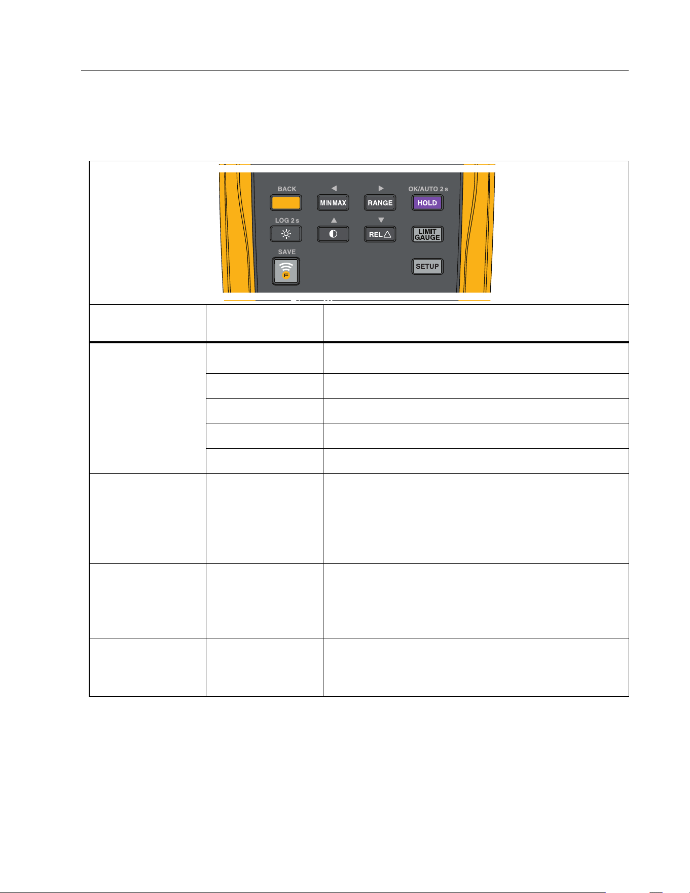
Pushbuttons
Table 3 is a list of the pushbutton functions.
Table 3. Pushbuttons
Button
Control Knob
Position
Function
BACK
N
E
Selects Frequency, VAC + AAC, VA + AAC.
4
Selects VDC + ADC, VA + ADC.
D
Selects ac millivolts.
C
B
Selects A ac.
3
Selects capacitance.
P
All positions
Starts the MIN MAX record function. Steps the
display through MAX, MIN, AVG (average), and input
signal measurement. Push for 2 second to stop
MIN MAX record.
is active for Contrast, Setup, and Limit Gauge.
S
All positions
Sets the Product to manual range and scrolls
through each range. Push for 2 second to set the
Product to autorange.
is active for Contrast, Setup, and Limit Gauge.
OK/AUTO 2 s
M
All positions
Freezes the display.
Auto Hold Mode, push >2 s.
OK is active for Contrast, Setup, and Limit Gauge.
1.888.610.7664 sales@GlobalTestSupply.com
Fluke-Direct
.com

283 FC
Users Manual
14
Button
Control Knob
Position
Function
LOG 2 s
O
Not related to
switch position
Push
O:
1x to turn on the display backlight
2x to illuminate the keypad
3x to turn off the backlight and the keypad
Data Log mode, push >2 s.
By default, the backlight automatically turns off
after 2 minutes. See Setup Menu to the change the
time interval.
Q
Not related to
switch position
Display contrast, use
to adjust.
is active for Setup and Limit Gauge.
R
All positions
except Hz, VA,
2
Relative Mode. Set the present reading as a
reference for subsequent readings. The display
reading is the difference between the live reading
and the reference value.
is active for Setup and Limit Gauge.
T
Voltage and
Current
measurements
only
Limit gauge is set as a high/low limit value or as a
percentage deviation from the expected value.
Press
T >2 s to toggle quick enable/disable.
Push
N to go back in the menu structure.
SAVE
L
Not related to
switch position
Turns on the radio. E shows on the display
when the radio is on.
Push to save and send the measurement to the
Fluke Connect App on mobile device.
[1]
Push >2 s. to exit the FC function.
U
Not related to
switch position
Connect to a283 FC clamp, set time, date, switch
on/off beeper, interval and duration for logging, and
view device info.
Push
N to go back in the menu structure.
[1] This button is used when the Product is paired with a wireless radio. See Wireless Radio Setup to learn
more.
Table 3. Pushbuttons (cont.)
1.888.610.7664 sales@GlobalTestSupply.com
Fluke-Direct
.com

True-RMS 1500 V Multimeter
Functions
15
Self Check
The Self Check feature tests the continuity of test leads and verifies the V dc and V ac
measurement engine, calibration status, and battery status.
To do a Self Check:
1. Turn the control knob to Self Check.
2. Short the test leads and push OK.
3. Wait several seconds until the test results show on the screen.
The screen shows these results:
Test Lead Check
The result is FAIL if the test lead is open or poor contact.
VDC 1500V
The result is PASS if the V dc measurement circuit path or measurement is normal.
The result is FAIL if the V dc measurement circuit path or measurement is abnormal.
VAC 300V/50Hz
The result is PASS if V ac measurement circuit path or measurement is normal.
The result is FAIL if V ac measurement circuit path or measurement is abnormal.
Battery
The battery voltage shows.
Calibration date
Shows the date for the last calibration and the recommendation for the next calibration.
I
f out of calibration cycle (see Setup Menu), the screen shows this message:
Calibration recommended
For example, the Meter time is 2027/6/16 and in Setup Menu the calibration cycle is set to
1 year. The Self Check recommends calibration since the calibration date is 2024/5/10
and the current date is 2027/6/16, which is out of the cycle.
Note
Follow the instructions on the display.
1.888.610.7664 sales@GlobalTestSupply.com
Fluke-Direct
.com
283 FC
Users Manual
16
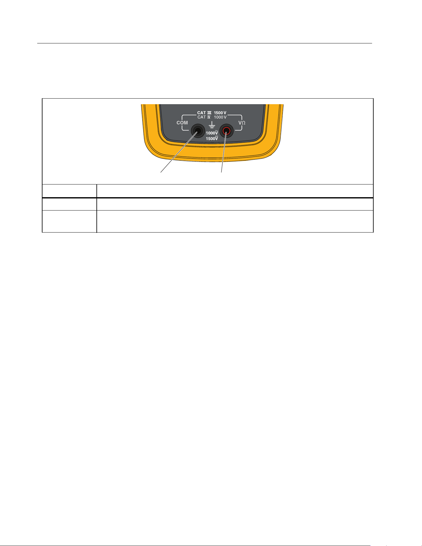
Inputs
Table 4 is a list of the input functions.
AC Low Value Input Behavior of True-RMS Meters
Average responding meters can accurately measure only pure sinewaves. The 283 FC
True-RMS Meter can accurately measure distorted waveform signals. A minimum input
voltage is necessary for True-RMS converters to make a measurement. Because of this
minimum input, True-RMS meter specifications are only good for 1 % to 100 % of range. Non-
zero digits that are shown on a True-RMS meter when the test leads are open or are shorted
are possible. This has no effect on the ac measurement accuracy of signals that are more than
1% of range.
Unspecified input levels on the lowest ranges are:
AC voltage less than 1 % of each V ac or mV ac range.
AC current less than 1 % of 60 A ac or 0.6 A ac.
Wireless Radio Setup
The Product uses wireless radio technology to send or receive measurements to the a283 FC
Current Clamp or the Fluke Connect® app. The maximum distance between meter and clamp
for operation is 10 m (33 ft).
Table 4. Inputs
Terminal Description
A
COM - Return terminal for all measurements.
B
Input for voltage, resistance, capacitance, voltage frequency, and Self
Check.
A
B
1.888.610.7664 sales@GlobalTestSupply.com
Fluke-Direct
.com

True-RMS 1500 V Multimeter
Functions
17
The term “pair” in this manual refers to a procedure the Product does to look for compatible
radio signals.
To turn on the radio:
1. Turn on the Product (the radio is off at the initial power on).
2. Push
L to turn on the radio.
When you turn on the radio,
E shows on the display.
Pair with Fluke Connect App
To pair with the Fluke Connect app:
1. Turn on the Product (the radio is off at the initial power on).
2. Push
L to turn on the radio.
When in the FC mode:
E shows on the display
L LED blinks at 4 to 5 second intervals
On your mobile device:
1. Go to Settings > Bluetooth. Verify that Bluetooth is turned on.
2. Go to the Fluke Connect app.
3. Select look for Fluke Connect tools and in the list of connected Fluke tools,
select
283
FC.
You can now take, save, and share measurements with the app.
Note
Use the FC App to automatically synchronize the date and time of the Meter.
Pair with a283 FC Current Clamp
The first time you set up the Meter and Clamp you must pair the tools. See the a283 FC
Wireless AC/DC Current Clamp Instructions for more information about how to operate the
Clamp.
Note
The Meter pairs with the Clamp for VA ac, VA dc, A ac, or A dc measurement functions.
1.888.610.7664 sales@GlobalTestSupply.com
Fluke-Direct
.com

283 FC
Users Manual
18
After the initial setup, the tools auto pair when you turn on power for both and are within the
wireless range.
To pair the Meter with the Clamp for the first use:
1. Turn on the Meter (the radio is off at the initial power on) and select the VA ac, VA dc, A ac,
or A dc measurement function.
2. Push
O to turn on the Clamp.
3. On the Meter, select VA ac, VA dc, A ac, or A dc function and push
U to open the Setup
menu.
4. In the menu, use
to highlight Clamp.
5. Push OK to start the search.
When the search is complete, the Meter shows the serial number of the Clamp. Use
to select the serial number of the target Clamp to pair with the Meter.
6. After the target Clamp is paired, push BACK to exit the Setup menu.
B shows at the right-top of the display.
The Meter is ready to show measurements from the Clamp. The maximum distance between
meter and clamp for operation is 10 m (33 ft).
Basic Measurements
XW Warning
To prevent possible electrical shock, fire, or personal injury, disconnect power
and discharge all high-voltage capacitors before you measure resistance,
continuity, or capacitance.
The figures that follow show how to make basic measurements with the Product.
When you connect the test leads to the circuit or device, connect the common (COM) test
lead before the live lead. When you remove the test leads, remove the live lead before the
common test lead.
1.888.610.7664 sales@GlobalTestSupply.com
Fluke-Direct
.com
True-RMS 1500 V Multimeter
Basic Measurements
19
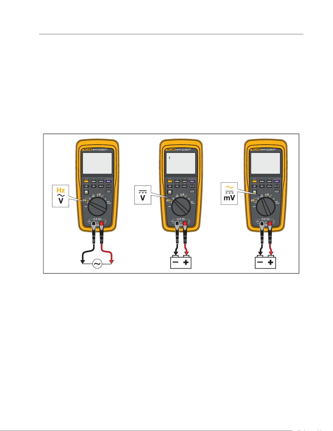
AC and DC Voltage
The ac voltage ranges are 600.0 mV, 6.000 V, 60.00 V, 600.0 V, and 1000 V. The dc voltage
ranges are 600.0 mV, 6.000 V. 60.00 V, 600.0 V, and 1500 V.
To set the 600.0 mV dc or ac range:
1. Turn the control knob to
D.
2. Push
N to toggle the Product between millivolts dc and ac.
3. Refer to Figure 2 to measure ac or dc voltage.
Figure 2. AC and DC Voltage Measurements
32.34
VDC
201.4
mVDC
Volts AC
Volts DC
Millivolts DC
12.01
VAC
Volts AC Volts DC mV DC/AC
1.888.610.7664 sales@GlobalTestSupply.com
Fluke-Direct
.com

283 FC
Users Manual
20
AC or DC Current with a283 FC Current Clamp
See Pair with a283 FC Current Clamp for more information about how to measure dc or ac
amps with the
C
B
function.
AC VA and DC Power
The ac VA or dc power measurement is a calculation between a voltage (using test leads
connected to the Meter) and an amperage input (from the Clamp):
Apparent Power (VA) = Voltage (V) × Current (A)
This calculated value shows on the display to save manual calculation and recording time.
You can use the Fluke Connect feature to share the calculation on your mobile device.
Note
The Meter only calculates apparent power (S, measured in VA) and not reactive power
(Q, measured in VAR) or True power (P, measured in Watts). For dc power there is no
difference in Watts and VA. For ac power the readout shows AC VA.
To measure dc power or ac VA:
1. Turn control knob to
E or 4.
2. Push
N to go to the A mode.
3. Make sure the Clamp is clear of any current carrying conductors.
4. On the Clamp, push
F to compensate (zero) for outside influences for dc power.
5. Position the Clamp jaw around the conductor.
6. Connect the black test lead to the COM terminal and the red test lead to the VΩ terminal.
7. Touch the probes to the test points of the circuit.
The display shows the measurement of VA and current.
The display also shows
B to indicate that the measurement is from the Clamp jaw.
Note
Push
N to toggle the readout between VA and voltage.
1.888.610.7664 sales@GlobalTestSupply.com
Fluke-Direct
.com
True-RMS 1500 V Multimeter
Basic Measurements
21
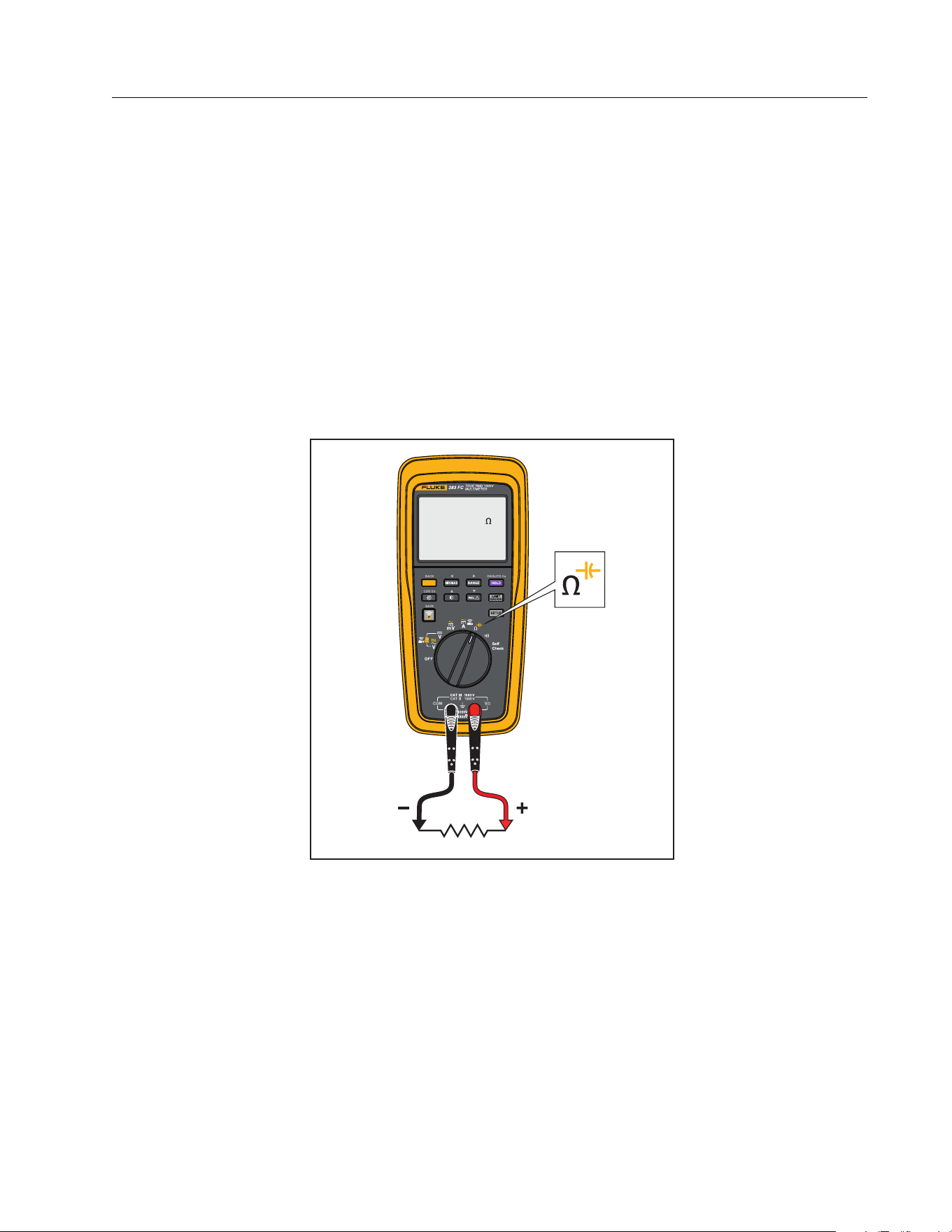
Resistance Measurements
XW Warning
To prevent possible electrical shock, fire, or personal injury, disconnect power
and discharge all high-voltage capacitors before you measure resistance,
continuity, or capacitance.
The Product sends a small current through the circuit for resistance measurements. Because
the current flows through all possible paths between the probes, the resistance measured is
the total resistance of all paths between the probes.
The resistance ranges are 600.0 Ω, 6.000 kΩ, 60.00 kΩ, 600.0 kΩ, 6.000 MΩ, and 50.00 MΩ. Set
the Product as shown in Figure 3 to measure resistance.
Figure 3. Resistance Measurements
25.01
M
1.888.610.7664 sales@GlobalTestSupply.com
Fluke-Direct
.com
283 FC
Users Manual
22
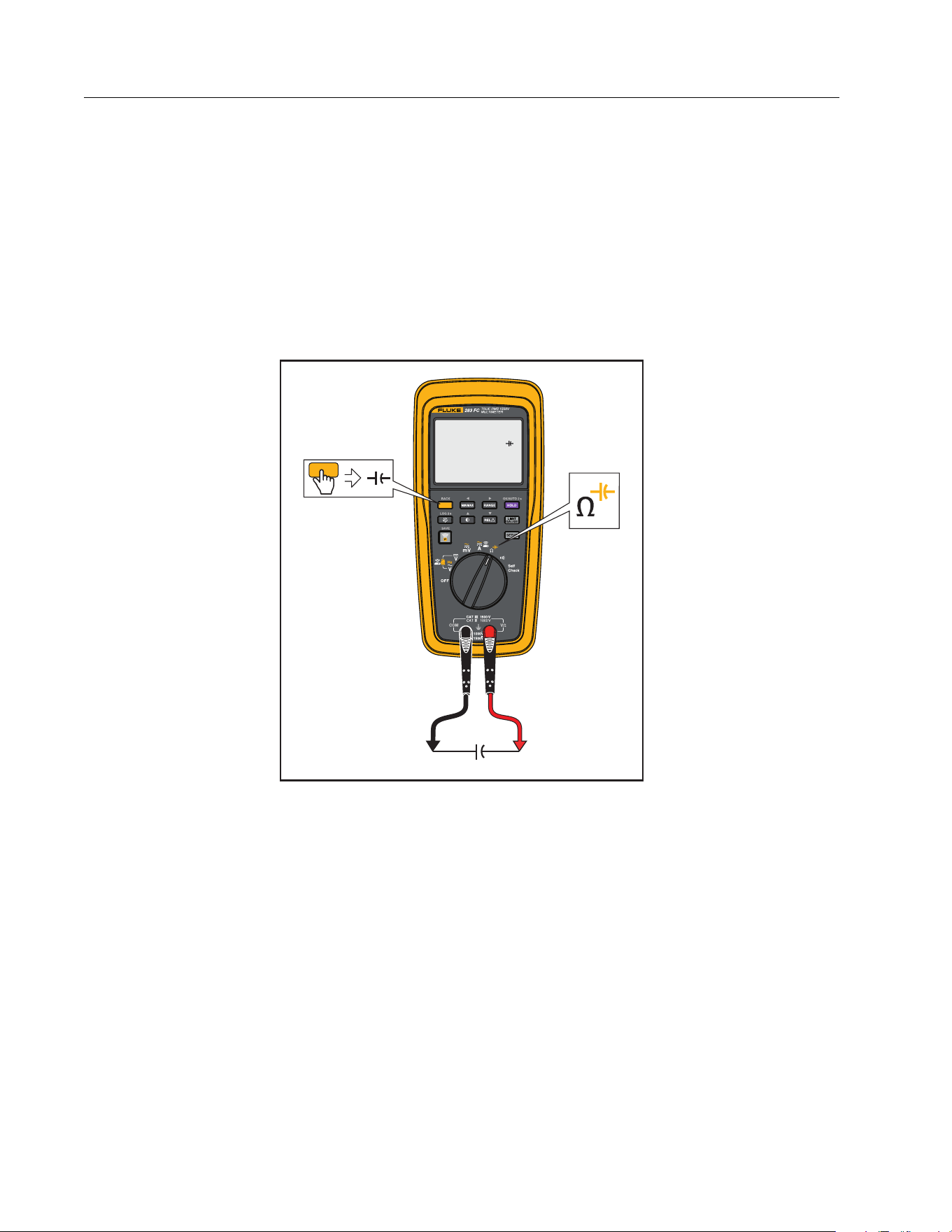
Capacitance Measurements
XW Warning
To prevent possible electrical shock, fire, or personal injury, disconnect power
and discharge all high-voltage capacitors before you measure resistance,
continuity, or capacitance.
Capacitance ranges are 1000 nF, 10.00 μF, 100.0 μF, and 9999 μF. To measure capacitance, set
up the Product as shown in Figure 4.
Figure 4. Capacitance Measurements
627
nF
1.888.610.7664 sales@GlobalTestSupply.com
Fluke-Direct
.com
True-RMS 1500 V Multimeter
Basic Measurements
23
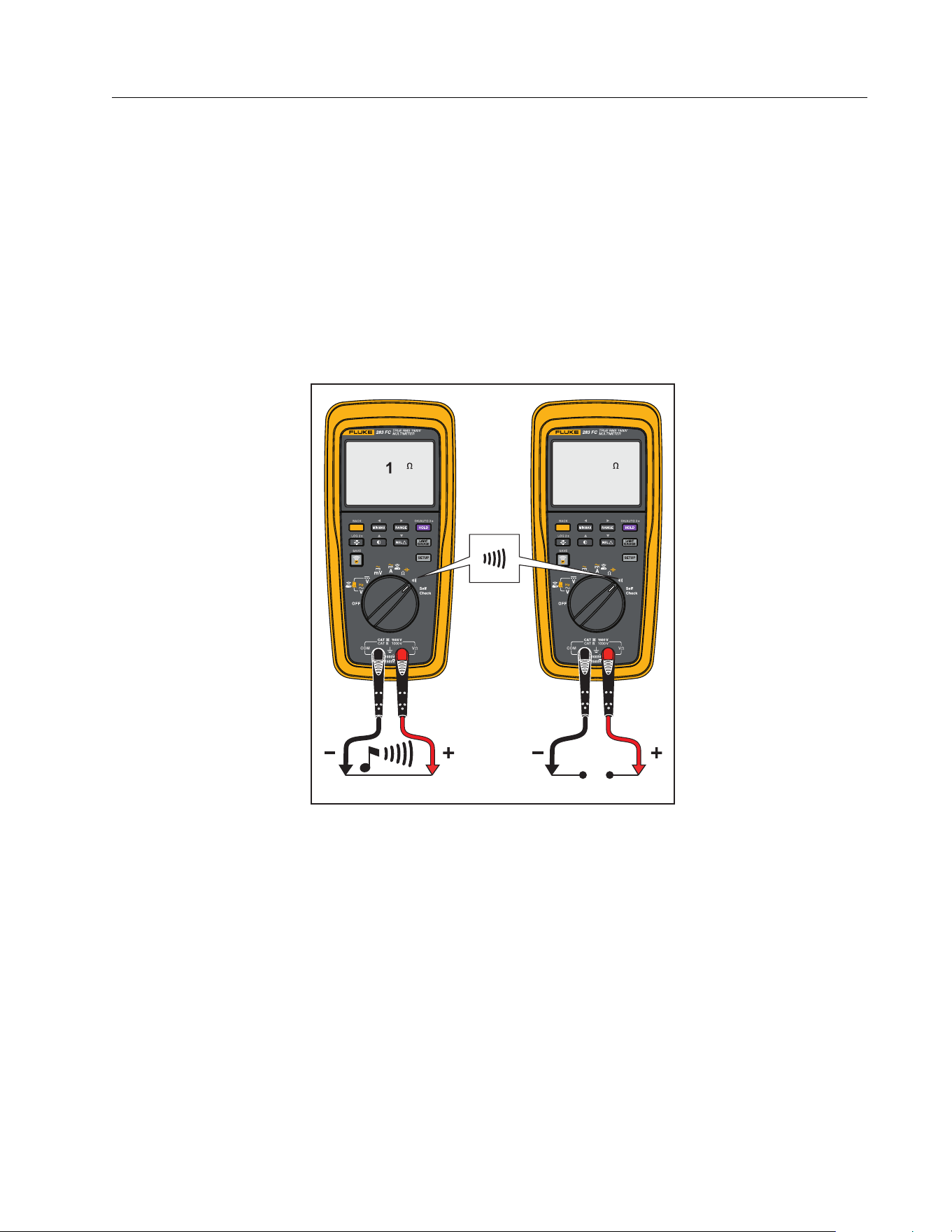
Continuity Test
XW Warning
To prevent possible electrical shock, fire, or personal injury, disconnect power
and discharge all high-voltage capacitors before you measure resistance,
continuity, or capacitance.
The continuity test uses a beeper that sounds when a closed circuit is sensed. The beeper lets
you do continuity tests without the necessity to look at the display. To do a continuity test, set
up the Product as shown in Figure 5.
Figure 5. Continuity Tests
R
R
60.OL
1.888.610.7664 sales@GlobalTestSupply.com
Fluke-Direct
.com
283 FC
Users Manual
24
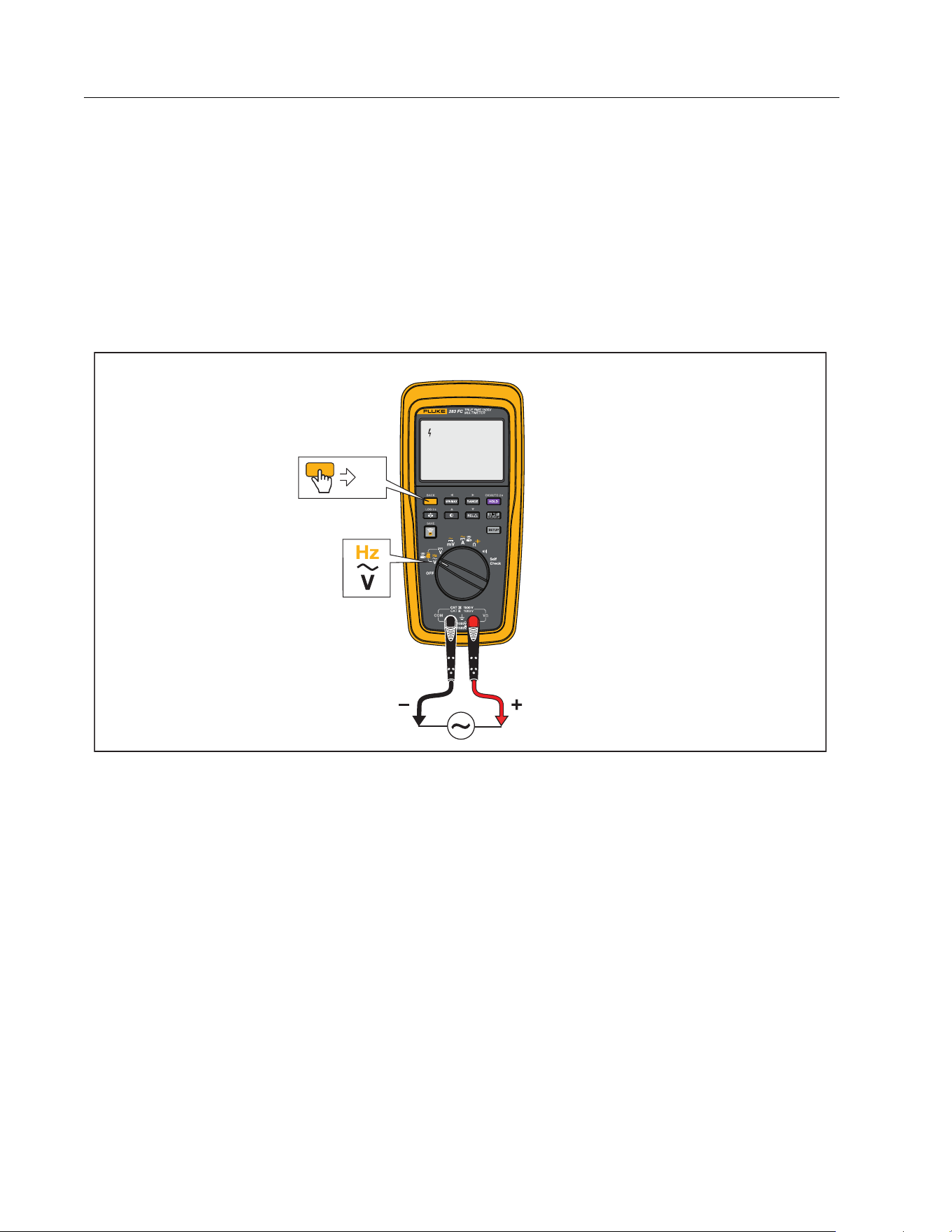
Frequency Measurement
A frequency measurement is a count of the number of times an ac voltage signal passes
through a threshold point each second.
The Product autoranges to one of four frequency ranges: 99.99 Hz, 999.9 Hz, 9.999 kHz, and
99.99 kHz. If a measurement shows 0 Hz or is not stable, the input signal can be below or near
a trigger level.
Set up the Product as shown in Figure 6 to measure frequency.
Figure 6. Frequency Measurement
Hz
60.00
Hz
1.888.610.7664 sales@GlobalTestSupply.com
Fluke-Direct
.com

True-RMS 1500 V Multimeter
Firmware Update
25
Firmware Update
Firmware updates are available with the Fluke Connect™ feature. The Fluke Connect mobile
app shows a notification if a firmware update is available when the unit is connected to the
app.
Note
When you upgrade firmware, logged data will be destroyed.
To update:
1. Make sure the Product has at least 4.0 V battery voltage available.
2. Make sure you download all the logged data before you update the firmware.
3. In the app, tap Update to start the firmware update to the Product.
Note
Depending on the update, a firmware update may take up to 90 minutes or longer.
Make sure you allow enough time before you begin the update.
Firmware Version
To find the installed firmware version for the Meter, see Device Information in Setup Menu.
Maintenance
XW Warning
To prevent a possible electrical shock or personal injury:
Have an approved technician repair the Meter.
Do not operate the Product with covers removed or the case open. Hazardous
voltage exposure is possible.
Use only specified replacement parts.
Remove the input signals before you clean the Product.
1.888.610.7664 sales@GlobalTestSupply.com
Fluke-Direct
.com

283 FC
Users Manual
26
General Maintenance
Clean the case with a damp cloth and weak detergent. Do not use a solvent or cleaners with
abrasives. Dirt or moisture in the terminals can cause incorrect measurements.
To clean the terminals:
1. Turn off the Product and remove all test leads.
2. Shake out dirt that can possibly be in the terminals.
3. Soak a clean swab with weak detergent and water.
4. Move the swab around in each terminal.
5. Dry each terminal with canned air to push the water and detergent out of the terminals.
XW Warning
To prevent electrical shock or personal injury, remove the test leads and all input
signals before you replace the batteries. To prevent damage or injury, install
ONLY specified replacement parts shown in Table 5.
Product Disposal
Dispose of the Product in a professional and environmentally sound manner:
Delete personal data on the Product before disposal.
Remove batteries that are not integrated into the electrical system before disposal and
dispose of batteries separately.
If this Product has an integral battery, put the entire Product in the electrical waste.
Battery Replacement
XW Warning
To prevent possible electrical shock, fire, or personal injury:
Remove the batteries if the Product is not used for an extended period of time, or
if stored in temperatures above 50 °C. If the batteries are not removed, battery
leakage can damage the Product.
Repair the Product before use if the battery leaks.
Be sure that the battery polarity is correct to prevent battery leakage.
Batteries contain hazardous chemicals that can cause burns or explode. If
exposure to chemicals occurs, clean with water and get medical aid.
1.888.610.7664 sales@GlobalTestSupply.com
Fluke-Direct
.com
True-RMS 1500 V Multimeter
Maintenance
27
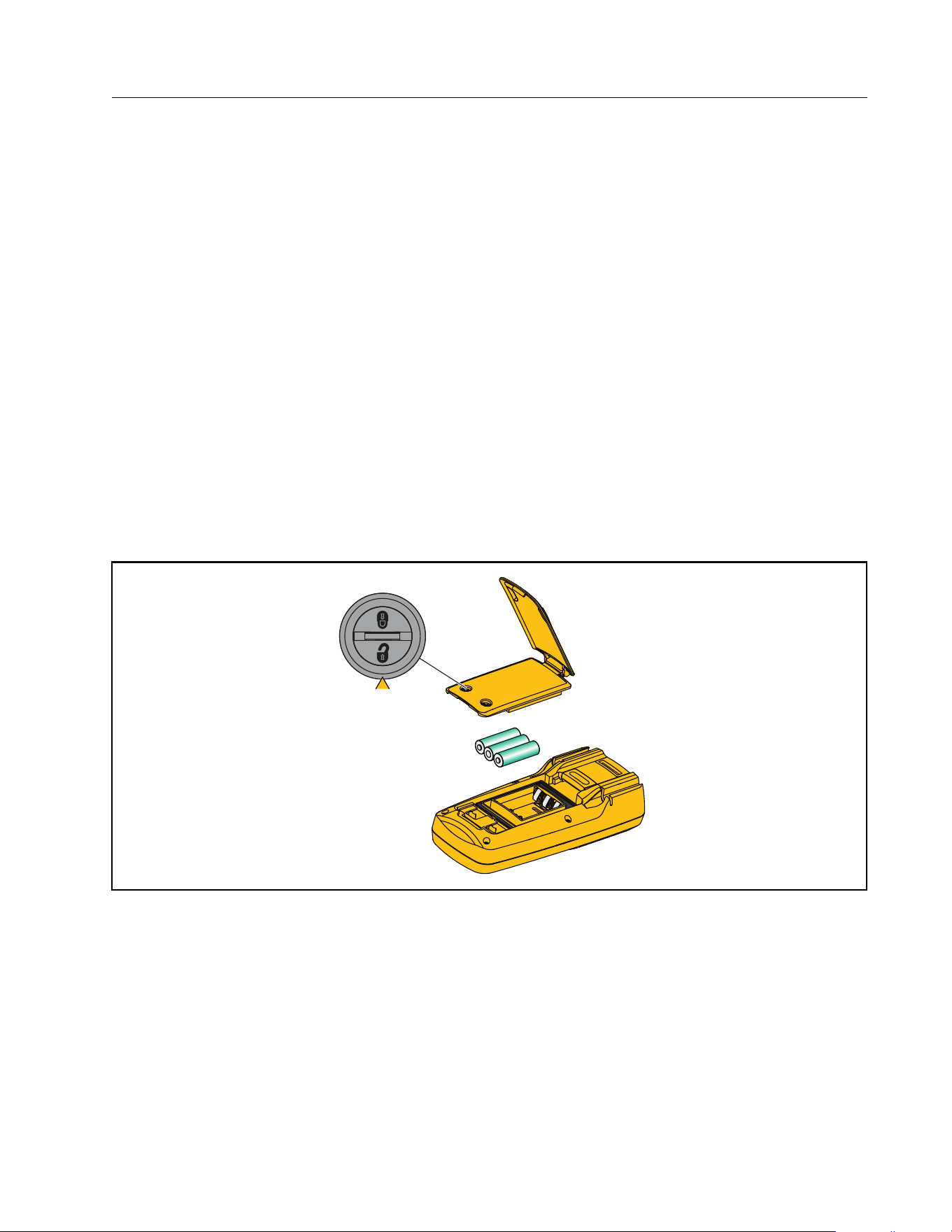
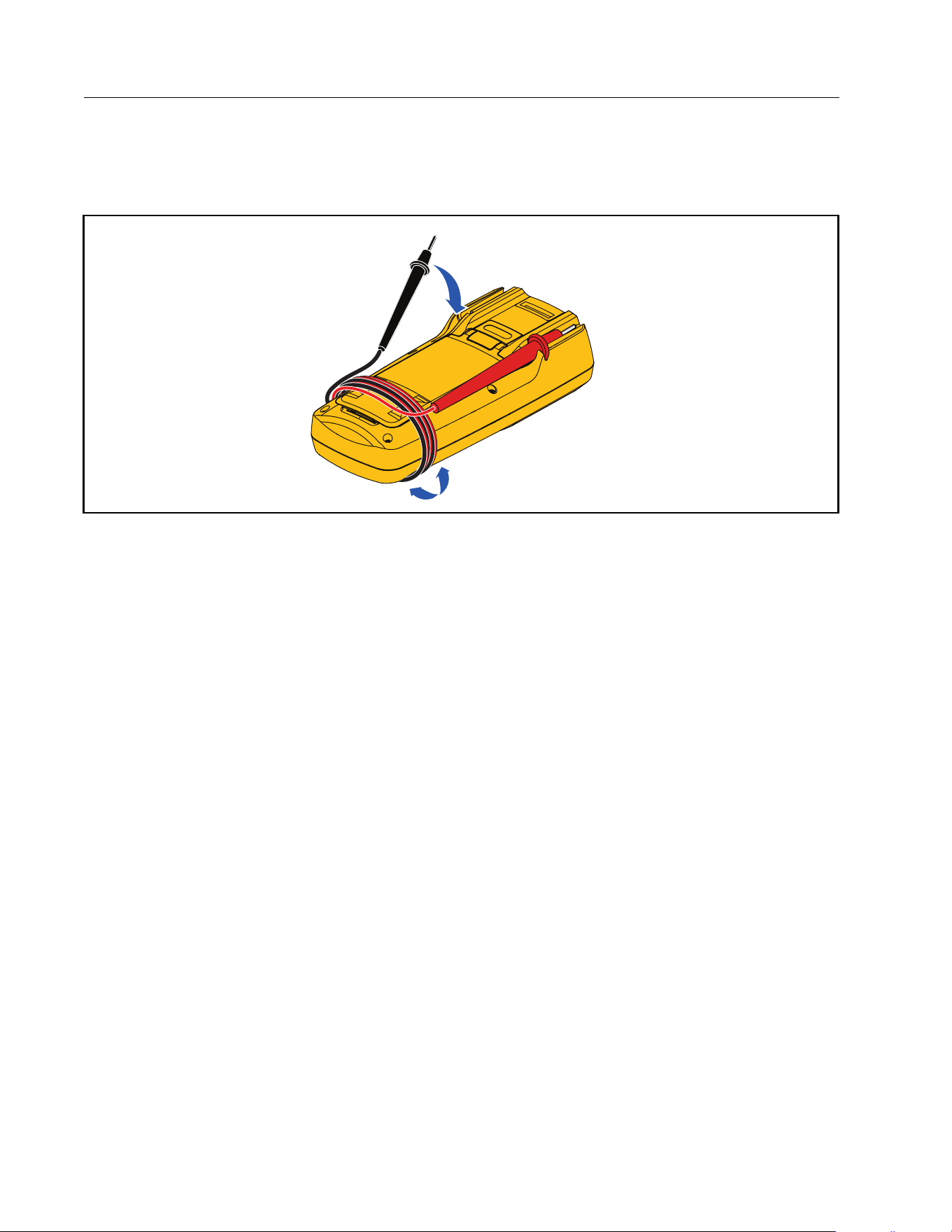
To replace the batteries:
1. Turn off the Product and remove all test leads.
2. Lift the tilt stand up as shown in Figure 7.
3. Turn each battery-door latch until the unlock symbol (
) aligns with the arrow.
4. Close the tilt stand and lift off the battery door assembly.
5. Remove the three AA batteries and replace them with new ones. Use the correct battery
orientation.
6. With the tilt stand closed, replace the battery door assembly.
Note
When fully open, the hinge on the tilt stand is locked and does not fit into place on the
Meter.
7. Lift the tilt stand up.
8. Turn both battery-door latches until the locked symbol (
) aligns with the arrow.
Figure 7. Battery Replacement
1.888.610.7664 sales@GlobalTestSupply.com
Fluke-Direct
.com
True-RMS 1500 V Multimeter
Service and Parts
29
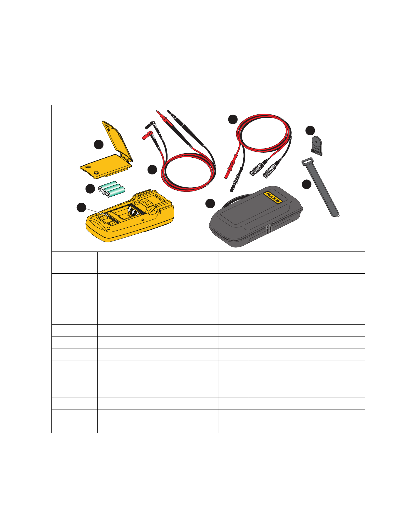
Service and Parts
If the Product fails to turn on, replace the batteries. Table 5 is a list of replacement parts. To
get parts, see Contact Fluke Corporation.
Table 5. Replacement Parts
Item Description Qty.
Fluke Part or
Model Number
A
Battery Door Assembly (includes
battery door, tilt stand, and two
latches)
1
(APAC) 5595070 + 5595096 + (2)
4320574
or
(AMER/EMEA) 6006667 +
5595096 + (2) 4320574
B
Battery, AA 1.5 V 3 376756
C
TL175-HV Test Lead Set 1 6002514
D
Gasket, Battery Door 1 5595129
E
MC4 Test Lead Set 1 5584869/5584878
F
Soft Case 1
5593525
G
TPAK80 Magnet 1
4329190
H
TPAK80 9 in Strap 1
5386922
not shown Quick Reference Guide 1 5593482
not shown Safety Information 1 5593502
4
2
6
3
1
7
5
8
1.888.610.7664 sales@GlobalTestSupply.com
Fluke-Direct
.com
283 FC
Users Manual
30
Specifications
General Specifications
Display
Update rate...................................................... 4/sec
Volts/amps/ohms .......................................... 6000 counts
Frequency........................................................ 9999 counts
Capacitance .................................................... 9999 counts
Battery
Type ................................................................... 3 AA, IEC LR6
Life...................................................................... >150 hr typical without backlight
>100 hr typical when connected to the wireless current clamp
Temperature Coefficient................................ 0.1 X (specified accuracy) /°C (<18 °C or >28 °C)
Wireless Frequency......................................... 2.4 GHz Band, 10 meter range
Size (HxWxL)....................................................... 22.5 cm x 10.5 cm x 5.7 cm (8.9 in x 4.1 in x 2.2 in)
Weight (with batteries).................................... 0.7 kg (1.5 lb)
Detailed Specifications
For all specifications:
Accuracy is specified for 1 year after calibration, at operating temperatures of 18 °C to 28 °C,
with relative humidity at 0 % to 90 %. Accuracy specifications take the form of ±([% of
Reading] + [Number of least significant digits]).
AC Voltage
Range
[1]
Resolution
Accuracy
[2][3][4]
45 Hz to 500 Hz 500 Hz to 1 kHz
6.000 V 0.001 V
1.0 % + 3 2.0 % + 3
60.00 V 0.01 V
600.0 V 0.1 V
1000 V 1 V
600.0 mV 0.1 mV
[1] All ac voltage ranges are specified from 1 % of range to 100 % of range.
[2] Crest factor of ≤3 at 4000 counts, decreasing linearly to 1.5 at full scale.
[3] For non-sinusoidal waveforms, add (2 % of reading + 2 % full scale) typical, for crest factor up to 3.
[4] Do not exceed 10
7
V-Hz
1.888.610.7664 sales@GlobalTestSupply.com
Fluke-Direct
.com
True-RMS 1500 V Multimeter
Specifications
31
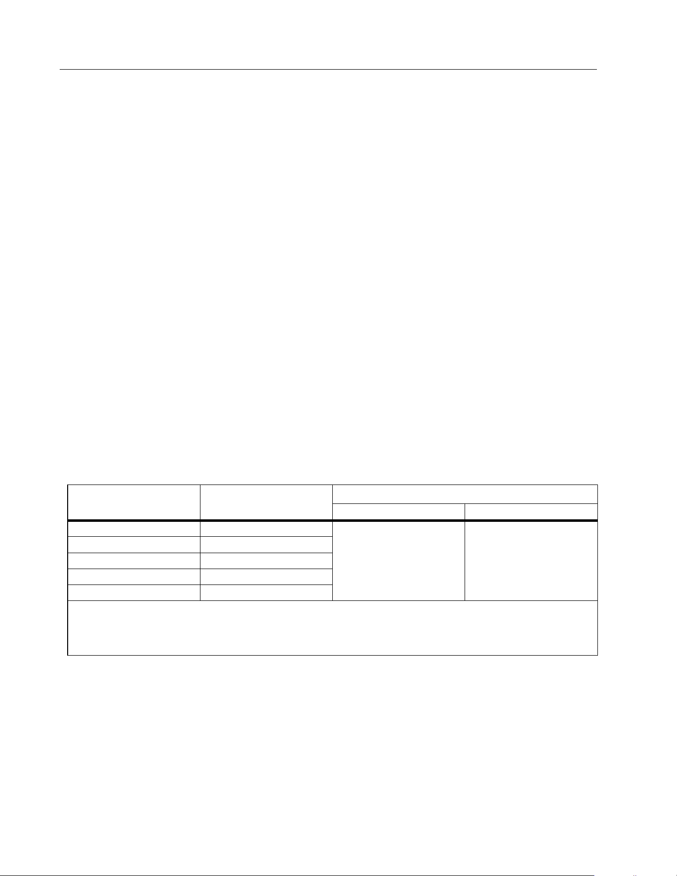
DC Voltage, Continuity, Resistance, and Capacitance
AC and DC Current
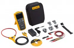
Current measurement only with optional accessory, a283 FC Wireless AC/DC Current Clamp.
For more information, see the a283 FC Wireless AC/DC Current Clamp Instructions. This
accessory is included in the 283 FC/PV kit. Current measurement up to 60 A.
Frequency
AC VA and DC Power
Function Range Resolution Accuracy
E
600.0 mV 0.1 mV 0.09 % + 2
D
6.000 V 0.001 V
0.09 % + 360.00 V 0.01 V
600.0 V 0.1 V
1500 V 1 V 0.15 % +2
s
600 Ω 1 Ω
Meter beeps at <70 Ω, beeper detects
opens or shorts of 250 μs or longer.
Ω
600.0 Ω 0.1 Ω 0.5 % + 4
6.000 kΩ 0.001 kΩ
0.5 % + 4
60.00 kΩ 0.01 kΩ
600.00 kΩ 0.1 kΩ
6.000 MΩ 0.001 MΩ
50.00 MΩ 0.01 MΩ 1.5 % + 4
N
1000 nF 1 nF
1.2 % + 210.00 μF0.01 μF
100.0 μF0.1 μF
9999 μF
[1]
1 μF 10 % typical
[1] In the 9999 μF range for measurements to 1000 μF, the measurement accuracy is 1.2 % + 2.
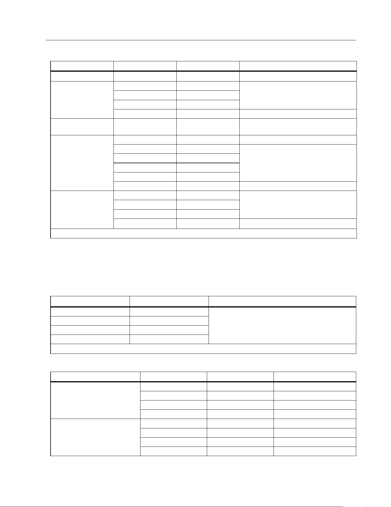
Range Resolution
Accuracy
[1]
99.99 Hz 0.01 Hz
0.1 % + 2
999.9 Hz 0.1 Hz
9.999 kHz 0.001 kHz
99.99 kHz 0.01 kHz
[1] Frequency is specified up to 99.99 kHz in volts.
Function Range Resolution Accuracy
AC VA
360.0 VA 0.1 VA 2 % +1.0 VA
3.600 kVA 0.001 kVA 2 % +0.01 kVA
36.00 kVA 0.01 kVA 2 % +0.1 kVA
60.00 kVA 0.01 kVA 2 % +0.15 kVA
DC Power
360.0 VA 0.1 VA 2 % +1.0 VA
3.600 kVA 0.001 kVA 2 % +0.01 kVA
36.00 kVA 0.01 kVA 2 % +0.1 kVA
90.00 kVA 0.01 kVA 2 % +0.25 kVA
1.888.610.7664 sales@GlobalTestSupply.com
Fluke-Direct
.com
283 FC
Users Manual
32
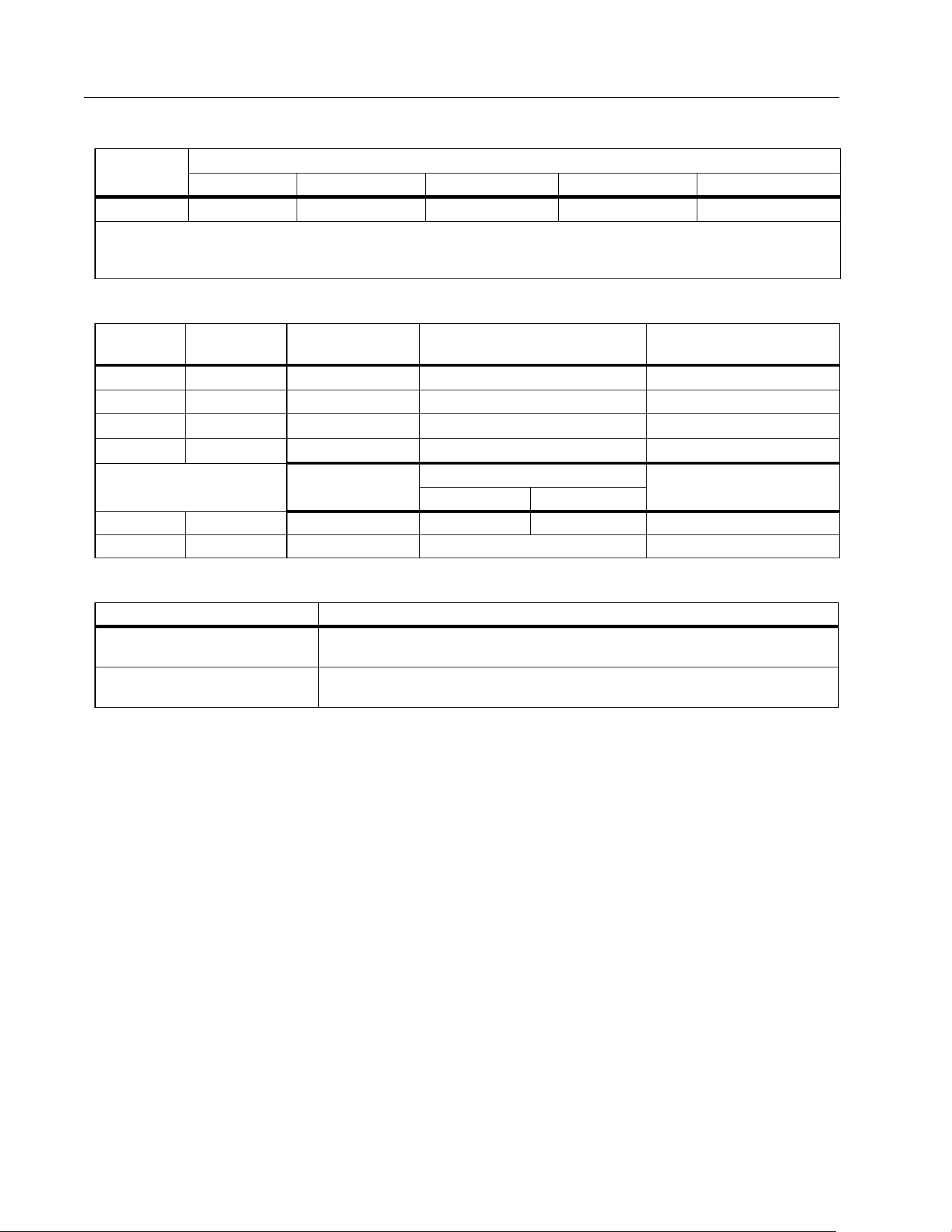
Frequency Counter Sensitivity
Input Characteristics
MIN MAX Recording
Input
Range
[1][2]
Typical Sensitivity (RMS Sine Wave)
2 Hz to 45 Hz 45 Hz to 10 kHz 10 kHz to 20 kHz 20 kHz to 50 kHz 50 kHz to 100 kHz
K
0.5 V 0.6 V 1.0 V 2.8 V
Unspecified
[3]
[1] Maximum input for specified accuracy = 10X Range or 1000 V.
[2] Noise at low frequency and amplitude may exceed the frequency accuracy specification.
[3] Unspecified but usable depending on quality and amplitude of signal.
Function
Overload
Protection
Input Impedance
(nominal)
Common Mode Rejection
Ratio (1 kΩ unbalance)
Normal Mode Rejection
L
1100 V rms >10 MΩ <100 pF >120 dB at dc, 50 Hz or 60 Hz >60 dB at 50 Hz or 60 Hz
K
1100 V rms >10 MΩ <100 pF >60 dB, dc to 60 Hz NA
E dc
1100 V rms >1 MΩ <100 pF >120 dB at dc, 50 Hz or 60 Hz >60 dB at 50 Hz or 60 Hz
E ac
1100 V rms >1 MΩ <100 pF >60 dB, dc to 60 Hz NA
Open Circuit
Test Voltage
Full Scale Voltage
Typical Short Circuit
Current
to 6 MΩ 50 MΩ
Ω /
E
1100 V rms <2.7 V dc <0.7 V dc <0.9 V dc <350 μA
R
1100 V rms <2.7 V dc 2.000 V dc <350 μA
Function Accuracy
DC Functions
The specified accuracy of the measurement function ±12 counts for changes
>350 ms in duration.
AC Functions
The specified accuracy of the measurement function ±40 counts for changes
>900 ms in duration.
1.888.610.7664 sales@GlobalTestSupply.com
Fluke-Direct
.com