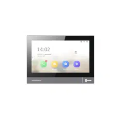

Video Intercom 9 Series Indoor
Staon
Operaon
Guide

Legal Informaon
©2022 Hangzhou Hikvision Digital Technology Co., Ltd. All rights reserved.
About this Manual
The Manual includes instrucons for using and managing the Product.
Pictures, charts, images and all other informaon hereinaer are for
descripon and explanaon only. The informaon contained in the Manual
is subject to change, without
noce, due to rmware updates or other
reasons. Please nd the latest version of this Manual at the Hikvision
website ( hps://w ww.hikvision.com/ ).
Please use this Manual with the guidance and assistance of professionals
trained in
supporng the Product.
Trademarks
and other Hikvision's trademarks and logos are the
properes of Hikvision in various jurisdicons.
Other trademarks and logos menoned are the properes of their
respecve owners.
Disclaimer
TO THE MAXIMUM EXTENT PERMITTED BY APPLICABLE LAW, THIS MANUAL
AND THE PRODUCT DESCRIBED, WITH ITS HARDWARE, SOFTWARE AND
FIRMWARE, ARE PROVIDED "AS IS" AND "WITH ALL FAULTS AND ERRORS".
HIKVISION MAKES NO WARRANTIES, EXPRESS OR IMPLIED, INCLUDING
WITHOUT LIMITATION, MERCHANTABILITY, SATISFACTORY QUALITY, OR
FITNESS FOR A PARTICULAR PURPOSE. THE USE OF THE PRODUCT BY YOU IS
AT YOUR OWN RISK. IN NO EVENT WILL HIKVISION BE LIABLE TO YOU FOR
ANY SPECIAL, CONSEQUENTIAL, INCIDENTAL, OR INDIRECT DAMAGES,
INCLUDING, AMONG OTHERS, DAMAGES FOR LOSS OF BUSINESS PROFITS,
BUSINESS INTERRUPTION, OR LOSS OF DATA, CORRUPTION OF SYSTEMS, OR
LOSS OF DOCUMENTATION, WHETHER BASED ON BREACH OF CONTRACT,
TORT (INCLUDING NEGLIGENCE), PRODUCT LIABILITY, OR OTHERWISE, IN
Video Intercom 9 Series Indoor
Staon Operaon Guide
i

CONNECTION WITH THE USE OF THE PRODUCT, EVEN IF HIKVISION HAS
BEEN ADVISED OF THE POSSIBILITY OF SUCH DAMAGES OR LOSS.
YOU ACKNOWLEDGE THAT THE NATURE OF THE INTERNET PROVIDES FOR
INHERENT SECURITY RISKS, AND HIKVISION SHALL NOT TAKE ANY
RESPONSIBILITIES FOR ABNORMAL OPERATION, PRIVACY LEAKAGE OR
OTHER DAMAGES RESULTING FROM CYBER-ATTACK, HACKER ATTACK, VIRUS
INFECTION, OR OTHER INTERNET SECURITY RISKS; HOWEVER, HIKVISION
WILL PROVIDE TIMELY TECHNICAL SUPPORT IF REQUIRED.
YOU AGREE TO USE THIS PRODUCT IN COMPLIANCE WITH ALL APPLICABLE
LAWS, AND YOU ARE SOLELY RESPONSIBLE FOR ENSURING THAT YOUR USE
CONFORMS TO THE APPLICABLE LAW. ESPECIALLY, YOU ARE RESPONSIBLE,
FOR USING THIS PRODUCT IN A MANNER THAT DOES NOT INFRINGE ON THE
RIGHTS OF THIRD PARTIES, INCLUDING WITHOUT LIMITATION, RIGHTS OF
PUBLICITY, INTELLECTUAL PROPERTY RIGHTS, OR DATA PROTECTION AND
OTHER PRIVACY RIGHTS. YOU SHALL NOT USE THIS PRODUCT FOR ANY
PROHIBITED END-USES, INCLUDING THE DEVELOPMENT OR PRODUCTION
OF WEAPONS OF MASS DESTRUCTION, THE DEVELOPMENT OR
PRODUCTION OF CHEMICAL OR BIOLOGICAL WEAPONS, ANY ACTIVITIES IN
THE CONTEXT RELATED TO ANY NUCLEAR EXPLOSIVE OR UNSAFE NUCLEAR
FUEL-CYCLE, OR IN SUPPORT OF HUMAN RIGHTS ABUSES.
IN THE EVENT OF ANY CONFLICTS BETWEEN THIS MANUAL AND THE
APPLICABLE LAW, THE LATTER PREVAILS.
Data Protecon
During the use of device, personal data will be collected, stored and
processed. To protect data, the development of Hikvision devices
incorporates privacy by design principles. For example, for device with facial
recognion features, biometrics data is stored in your device with
encrypon method; for ngerprint device, only ngerprint template will be
saved, which is impossible to reconstruct a ngerprint image.
As data controller, you are advised to collect, store, process and transfer
data in accordance with the applicable data
protecon laws and regulaons,
including without limitaon, conducng security controls to safeguard
personal data, such as, implemenng reasonable administrave and
physical security controls, conduct periodic reviews and assessments of the
eecveness of your security controls.
Video Intercom 9 Series Indoor
Staon Operaon Guide
ii
Symbol Convenons
The symbols that may be found in this document are dened as follows.
Symbol Descripon
Danger
Indicates a hazardous situaon which, if not avoided, will or
could result in death or serious injury.
Cauon
Indicates a potenally hazardous situaon which, if not
avoided, could result in equipment damage, data loss,
performance degradaon, or unexpected results.
Note
Provides addional informaon to emphasize or
supplement important points of the main text.
Video Intercom 9 Series Indoor Staon Operaon Guide
iii

Safety Instrucon
Warning
●
All the electronic operaon should be strictly compliance with the electrical safety
regulaons, re prevenon regulaons and other related regulaons in your local
region.
●
Please use the power adapter, which is provided by normal company. The power
consumpon cannot be less than the required value.
●
Do not connect several devices to one power adapter as adapter overload may
cause over-heat or re hazard.
●
Please make sure that the power has been disconnected before you wire, install or
dismantle the device.
●
When the product is installed on wall or ceiling, the device shall be
rmly xed.
●
If smoke, odors or noise rise from the device, turn
o the power at once and
unplug the power cable, and then please contact the service center.
●
If the product does not work properly, please contact your dealer or the nearest
service center. Never aempt to disassemble the device yourself. (We shall not
assume any responsibility for problems caused by unauthorized repair or
maintenance.)
Cauon
●
Do not drop the device or subject it to physical shock, and do not expose it to high
electromagnesm radiaon. Avoid the equipment installaon on vibraons
surface or places subject to shock (ignorance can cause equipment damage).
●
Do not place the device in extremely hot (refer to the specicaon of the device
for the detailed operang temperature), cold, dusty or damp locaons, and do not
expose it to high electromagnec radiaon.
●
The device cover for indoor use shall be kept from rain and moisture.
●
Exposing the equipment to direct sun light, low venlaon or heat source such as
heater or radiator is forbidden (ignorance can cause
re danger).
●
Do not aim the device at the sun or extra bright places. A blooming or smear may
occur otherwise (which is not a malfuncon however), and aecng the
endurance of sensor at the same me.
Video Intercom 9 Series Indoor
Staon Operaon Guide
iv
●
Please use the provided glove when open up the device cover, avoid direct contact
with the device cover, because the acidic sweat of the ngers may erode the
surface coang of the device cover.
●
Please use a so and dry cloth when clean inside and outside surfaces of the
device cover, do not use alkaline detergents.
●
Please keep all wrappers aer unpack them for future use. In case of any failure
occurred, you need to return the device to the factory with the original wrapper.
Transportaon without the original wrapper may result in damage on the device
and lead to
addional costs.
●
Improper use or replacement of the baery may result in hazard of explosion.
Replace with the same or equivalent type only. Dispose of used baeries
according to the instrucons provided by the baery manufacturer.
●
Input voltage should meet both the SELV and the Limited Power Source according
to 60950-1 standard.
●
The power supply must conform to LPS. The recommended adaptor models and
manufacturers are shown as below. Use the aached adapter, and do not change
the adaptor randomly.
Model Current Manufacturer Standard
MSA-C1500IC12.0-18P-
US
1.5 A MOSO POWER SUPPLY
TECHNOLOGY CO., LTD
PG
TS-A018-120015AD 1.5 A SHENZHEN TRANSIN
TECHNOLOGIES CO., LTD
PG
●
Improper use or replacement of the baery may result in hazard of explosion.
Replace with the same or equivalent type only. Dispose of used baeries
according to the instrucons provided by the baery manufacturer.
●
Improper replacement of the baery with an incorrect type may defeat a
safeguard (for example, in case of some lithium baery types).
●
Do not dispose of the baery into re or a hot oven, or mechanically crush or cut
the baery, which may result in an explosion.
●
Do not leave the baery in an extremely high temperature surrounding
environment, which may result in an explosion or leakage of ammable liquid or
gas.
●
Do not subject the baery to extremely low air pressure, which may result in an
explosion or the leakage of ammable liquid or gas.
●
CAUTION: Risk of explosion if the
baery is replaced by an incorrect type.
Video Intercom 9 Series Indoor
Staon Operaon Guide
v

Regulatory Informaon
FCC Informaon
Please take aenon that changes or modicaon not expressly approved
by the party responsible for compliance could void the user's authority to
operate the equipment.
FCC compliance: This equipment has been tested and found to comply with
the limits for a Class B digital device, pursuant to part 15 of the FCC Rules.
These limits are designed to provide reasonable protecon against harmful
interference in a residenal installaon. This equipment generates, uses and
can radiate radio frequency energy and, if not installed and used in
accordance with the instrucons, may cause harmful interference to radio
communicaons. However, there is no guarantee that interference will not
occur in a parcular installaon. If this equipment does cause harmful
interference to radio or television recepon, which can be determined by
turning the equipment o and on, the user is encouraged to try to correct
the interference by one or more of the following measures:
—Reorient or relocate the receiving antenna.
—Increase the separaon between the equipment and receiver.
—Connect the equipment into an outlet on a circuit dierent from that to
which the receiver is connected.
—Consult the dealer or an experienced radio/TV technician for help
This equipment should be installed and operated with a minimum distance
20cm between the radiator and your body.
FCC
Condions
This device complies with part 15 of the FCC Rules. Operaon is subject to
the following two condions:
1. This device may not cause harmful interference.
2. This device must accept any interference received, including interference
that may cause undesired
operaon.
Video Intercom 9 Series Indoor
Staon Operaon Guide
vi
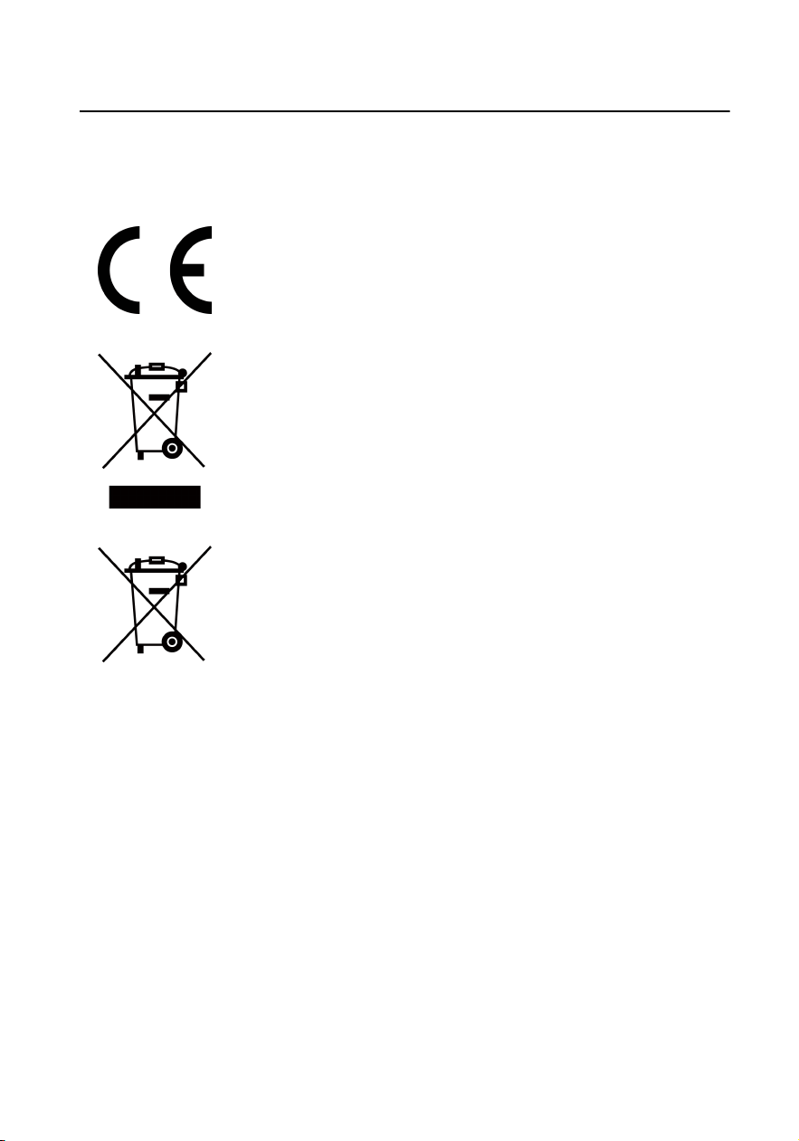
EU Conformity Statement
This product and - if applicable - the supplied accessories too are
marked with "CE" and comply therefore with the applicable
harmonized European standards listed under the EMC Direcve
2014/30/EU, RE Direcve 2014/53/EU,the RoHS Direcve 2011/
65/EU
2012/19/EU (WEEE direcve): Products marked with this symbol
cannot be disposed of as unsorted municipal waste in the
European Union. For proper recycling, return this product to your
local supplier upon the purchase of equivalent new equipment, or
dispose of it at designated collecon points. For more informaon
see: www.recyclethis.info
2006/66/EC (baery direcve): This product contains a baery
that cannot be disposed of as unsorted municipal waste in the
European Union. See the product documentaon for specic
baery informaon. The baery is marked with this symbol,
which may include leering to indicate cadmium (Cd), lead (Pb),
or mercury (Hg). For proper recycling, return the
baery to your
supplier or to a designated collecon point. For more informaon
see:www.recyclethis.info
Industry Canada ICES-003 Compliance
This device meets the CAN ICES-3 (B)/NMB-3(B) standards requirements.
This device complies with Industry Canada licence-exempt RSS standard(s).
Operaon is subject to the following two condions:
1.
this device may not cause interference, and
2.
this device must accept any interference, including interference that may
cause undesired operaon of the device.
Le présent appareil est conforme aux CNR d'Industrie Canada applicables
aux appareils radioexempts de licence. L'exploitaon est autorisée aux deux
condions suivantes :
Video Intercom 9 Series Indoor
Staon Operaon Guide
vii

1.
l'appareil ne doit pas produire de brouillage, et
2.
l'ulisateur de l'appareil doit accepter tout brouillage radioélectrique
subi, même si le brouillage est suscepble d'en compromere le
fonconnement.
Under Industry Canada regulaons, this radio transmier may only operate
using an antenna of a type and maximum (or lesser) gain approved for the
transmier by Industry Canada. To reduce potenal radio interference to
other users, the antenna type and its gain should be so chosen that the
equivalent isotropically radiated power (e.i.r.p.) is not more than that
necessary for successful communicaon.
Conformément à la réglementaon d'Industrie Canada, le présent émeeur
radio peut fonconner avec une antenne d'un type et d'un gain maximal (ou
inférieur) approuvé pour l'émeeur par Industrie Canada. Dans le but de
réduire les risques de brouillage radioélectrique à l'intenon des autres
ulisateurs, il faut choisir le type d'antenne et son gain de sorte que la
puissance isotrope rayonnée équivalente (p.i.r.e.) ne dépasse pas l'intensité
nécessaire à l'établissement d'une communicaon sasfaisante.
This equipment should be installed and operated with a minimum distance
20cm between the radiator and your body.
Cet équipement doit être installé et
ulisé à une distance minimale de 20
cm entre le radiateur et votre corps.
Video Intercom 9 Series Indoor
Staon Operaon Guide
viii

Contents
1 About this Manual ...................................................................................... 1
2 Wake Up the Device ................................................................................... 2
3 Main Page Introducon .............................................................................. 3
4 Local
Operaon .......................................................................................... 7
4.1 Call Sengs ....................................................................................................... 7
4.1.1 VoIP Account Sengs ............................................................................... 7
4.1.2 Add Contact .............................................................................................. 7
4.1.3 Call Resident ............................................................................................. 9
4.1.4 Call Indoor Extension/Indoor
Staon ..................................................... 10
4.1.5 Receive Call ............................................................................................. 10
4.1.6 View Call Logs ......................................................................................... 10
4.2 Live View ......................................................................................................... 11
4.3 Arm/Disarm ..................................................................................................... 12
4.3.1 Arm Room ............................................................................................... 12
4.3.2 Disarm Your Room .................................................................................. 13
4.4 Arming Mode
Sengs ..................................................................................... 13
4.5 Informaon Management ............................................................................... 15
5 Remote
Operaon via Mobile Client ........................................................ 19
5.1 Set up Mobile Client ........................................................................................ 19
5.2 Set Up Device via Mobile Client ...................................................................... 19
5.3 Remote Operaon ........................................................................................... 20
Video Intercom 9 Series Indoor
Staon Operaon Guide
ix

6 Remote Operaon via the client soware ............................................... 21
6.1 Call Indoor Staon ........................................................................................... 21
6.2 Receive Call from Indoor
Staon/Door Staon ............................................... 22
6.3 View Live Video of Door Staon and Outer Door Staon ............................... 22
6.4 View Call Logs ................................................................................................. 23
6.5 Release Noce ................................................................................................ 23
6.6 Search Video Intercom Informaon ................................................................ 26
6.6.1 Search Call Logs ...................................................................................... 26
6.6.2 Search
Noce .......................................................................................... 27
A. Communicaon Matrix and Device Command ....................................... 30
Video Intercom 9 Series Indoor
Staon Operaon Guide
x
1 About this Manual
Get the manual and related soware from or the ocial website (hp://
www.hikvision.com).
Product Model
Network Indoor Staon
DS-KH9310-WTE1(B)/DS-KH9510-
WTE1(B)
Video Intercom 9 Series Indoor Staon Operaon Guide
1

2 Wake Up the Device
You should wake up the device from the standby mode to enter the main page.
When you enable the gesture password funcon, you should enter the gesture
password to unlock the device.
Steps
1. Touch the screen to wake up the deivce.
2. Enter the gesture password to unlock the device.
Note
●
When you forget the gesture password, you can tap Forgot Gesture Password
or Use admin password to enter admin password to unlock.
●
When you tap Sengs → Advanced Sengs to disable Unlock by Gesture, you
can skip the step.
Video Intercom 9 Series Indoor Staon Operaon Guide
2
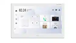
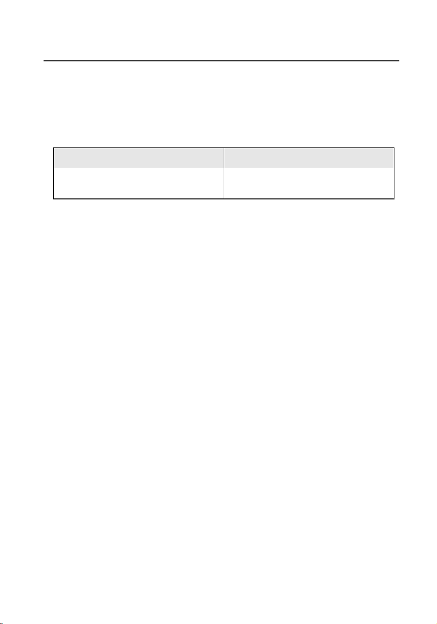
3 Main Page Introducon
Wake up the device. Refers to Wake Up the Device for details.
Main Page Introducon
On the home page of the device, you can slide up or down to enter the call
page, alarm page and the third-party App sengs page.
Figure 3-1 Main Page
Main Page
You can call resident, view and add contact, live view remotely, arm or
disarm the device on the main page.
One-Push to Arm/Disarm
Tap to
arm or disarm the device.
Relay Sengs
Tap to enable or disable the relays you have set.
SOS
Tap to call SOS.
Call Elevator
Video Intercom 9 Series Indoor
Staon Operaon Guide
3
When the device is connect to the elevator controller, tap to call
elevator.
Call Center
Tap
to call center.
Lock the Screen
Tap to lock the screen.
Mobile Client Sengs
Tap + to add the account to the mobile client. And you can operate
the device remotely via mobile client.
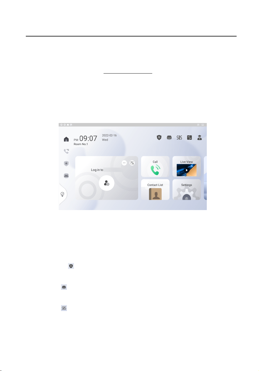
Call Page
You can view call logs and search
noce on the call page.
Figure 3-2 Call Page
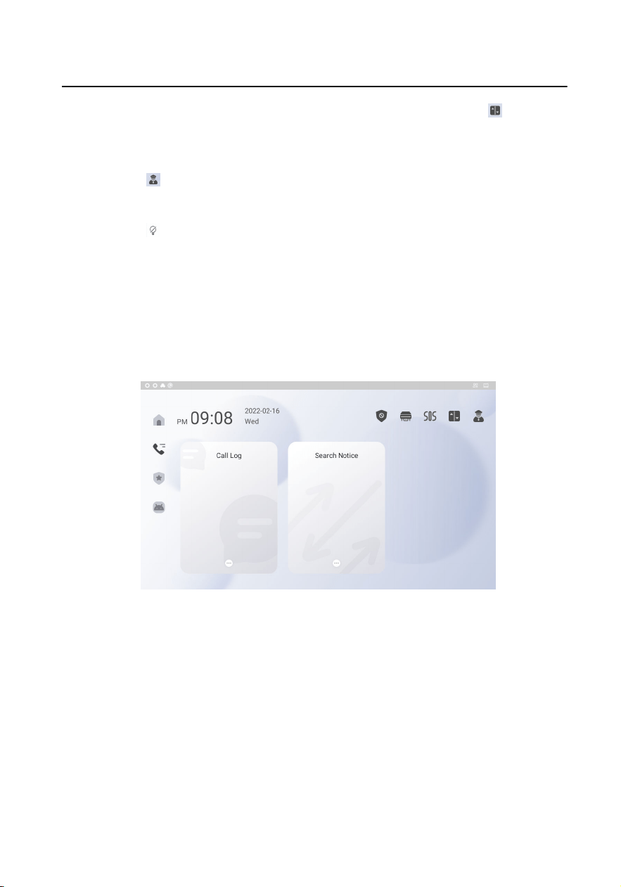
Alarm Page
You can view alarm logs, pictures in album on the alarm page.
Video Intercom 9 Series Indoor
Staon Operaon Guide
4
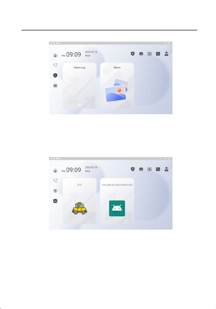
Figure 3-3 Alarm Page
The Third-Party App Sengs Page
You can add or run the third-party Apps on the third-party App sengs
page.
Figure 3-4 The Third-Party App Sengs Page
Shortcut Control Center
Slide up from the boom of the screen, you can set the device easily.
Video Intercom 9 Series Indoor
Staon Operaon Guide
5
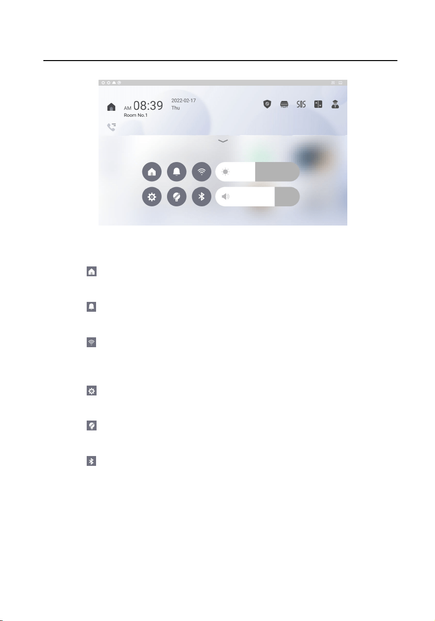
Figure 3-5 Control Center
Go Back to the Main Page
Tap
can go back to the main page of the device from any page.
Do Not Disturb
Tap to enable or disable the Do Not Disturb funcon.
Wi-Fi
Tap to enable or disable the Wi-Fi funcon, and you can connect to
wireless network.
Sengs
Tap to enter the sengs page.
Lock the Screen
Tap to lock the screen.
Bluetooth
Tap to enable or disable the bluetooth funcon.
Adjust Brightness
Slide to adjust the brightness of the screen.
Adjust Volume
Slide to adjust the volume of the device.
Video Intercom 9 Series Indoor
Staon Operaon Guide
6
4 Local Operaon
4.1 Call Sengs
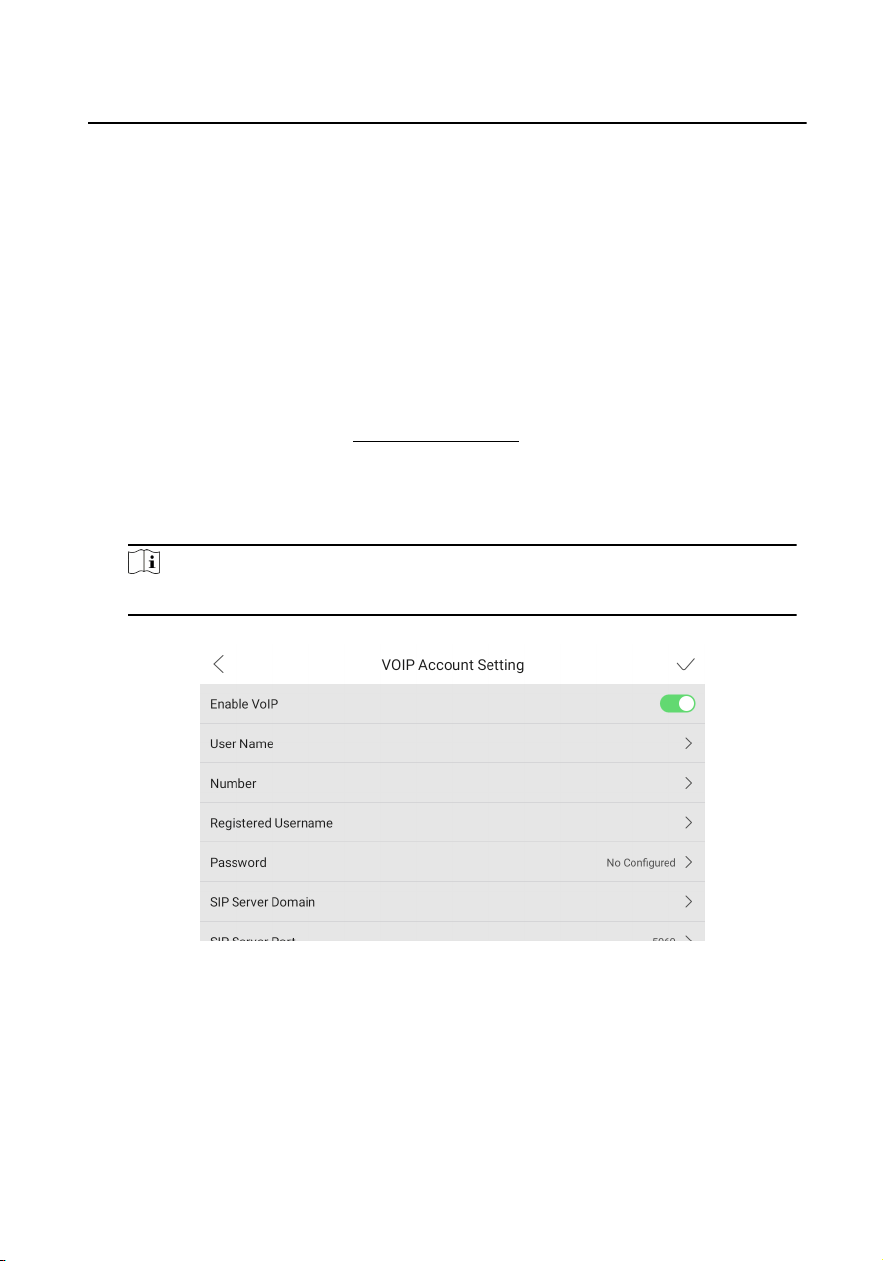
4.1.1 VoIP Account Sengs
Enable VoIP account funcons, and others can call via VoIP number you have set.
Before You Start
Wake up the device. Refers to Wake Up the Device for details.
Steps
1. On the main page of the device, tap Sengs → Advanced Sengs → VoIP
Account Sengs to enter the sengs page.
Note
Admin password is required to enter the advanced sengs page.
Figure 4-1 VoIP Account Sengs
2. Enable the funcon.
3. Set the parameters according to your needs and the page.
4. Tap √ to enable the
sengs.
4.1.2 Add Contact
Video Intercom 9 Series Indoor Staon Operaon Guide
7
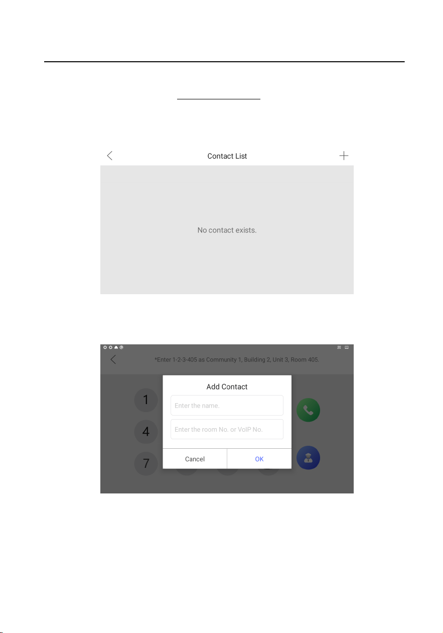
Before You Start
Wake up the device. Refers to Wake Up the Device for details.
Steps
1. On the main page of the device, tap Contact List to enter the contact list page.
Figure 4-2 Contact List
2. Tap + to pop up the contact adding dialog.
Figure 4-3 Add Contact
3. Enter the contact name and room No.
Video Intercom 9 Series Indoor
Staon Operaon Guide
8
Note
If you enable the VoIP account funcons, you should enter the contact name and
the phone number of VOIP account for the standard SIP protocol.
4. Tap OK to save the sengs.
Note
Up to 200 contacts can be added.
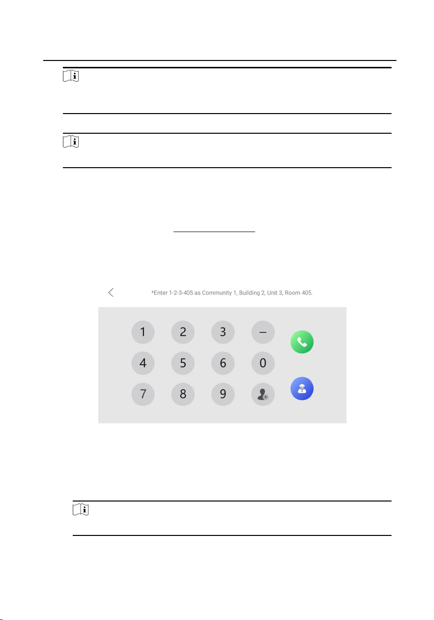
4.1.3 Call Resident
Before You Start
Wake up the device. Refers to Wake Up the Device for details.
Steps
1. On the main page of the device, tap Call to enter the residents calling page.
Figure 4-4 Call Resident
2. Enter the calling number to call.
-
If you want to call room, the calling number format should be x-x-x-xxx. For
example, the calling number of Community 1, Building 2, Unit 3, and Room 405
is 1-2-3-405. Tap the call buon to start an audiovisual call.
Note
The community No. can be omied.
-
If you want to call VoIP contact, the calling number should be the phone
number of VoIP account.
Video Intercom 9 Series Indoor
Staon Operaon Guide
9

4.1.4 Call Indoor Extension/Indoor Staon
If you install indoor staon and indoor extensions at home, you can call the indoor
extension via your indoor staon, and vice versa. If you have installed more than 2
indoor extensions, you can also call the indoor extension from the indoor extension.
Call Indoor Extension from Indoor Staon
Enter 【0-indoor extension No.】 on the indoor staon to start calling the
target indoor extension.
Call Indoor Staon from Indoor Extension
Enter 【0-0】 on the indoor extension to call the indoor staon from the
indoor extension.
Call Indoor Extension from Indoor Extension
Enter 【0-indoor extension No.】 on the indoor extension to start calling the
target indoor extension.
4.1.5 Receive Call
The indoor staon and indoor extension can receive calls from the door staon, the
main staon or iVMS-4200 Client.
On the call from door staon interface, there are 2 unlock buons: Unlock 1, and
Unlock 2. When you tap Unlock 1, the building gate will open by default, and when
you tap Unlock 2, the door connected to the door staon with the secure control
door unit will open.
Tap the capture buon to capture the live view picture when speaking with the door
staon. And prompts "Captured" will display on the screen.
Indoor extension can receive calls from the door staon and the main staon only.
4.1.6 View Call Logs
Before You Start
Wake up the device. Refers to Wake Up the Device for details.
Video Intercom 9 Series Indoor
Staon Operaon Guide
10
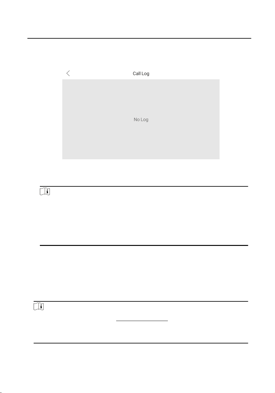
Steps
1. On the main page of the device, tap → Call Log to enter the call log page.
Figure 4-5 Call Logs
2. Tap a piece of call logs in the list to call back.
Note
●
Indoor extension does not support this funcon.
●
The indoor staon saves call logs from door staon, outer door staon,
management center and other indoor staons.
●
Hold a piece of call logs, and tap Delete Logs to delete.
●
Tap Clear to delete all pieces of call logs.
4.2 Live View
On the live view page, you can view the live video of added door staon and
network camera.
Steps
Note
●
Wake up the device. Refers to Wake Up the Device for details.
●
Make sure the network camera or door staon is well-connected.
●
Make sure the indoor extension and the indoor staon are well-connected.
1.
On the main page of the device, tap Live View to enter the live view page.
Video Intercom 9 Series Indoor
Staon Operaon Guide
11
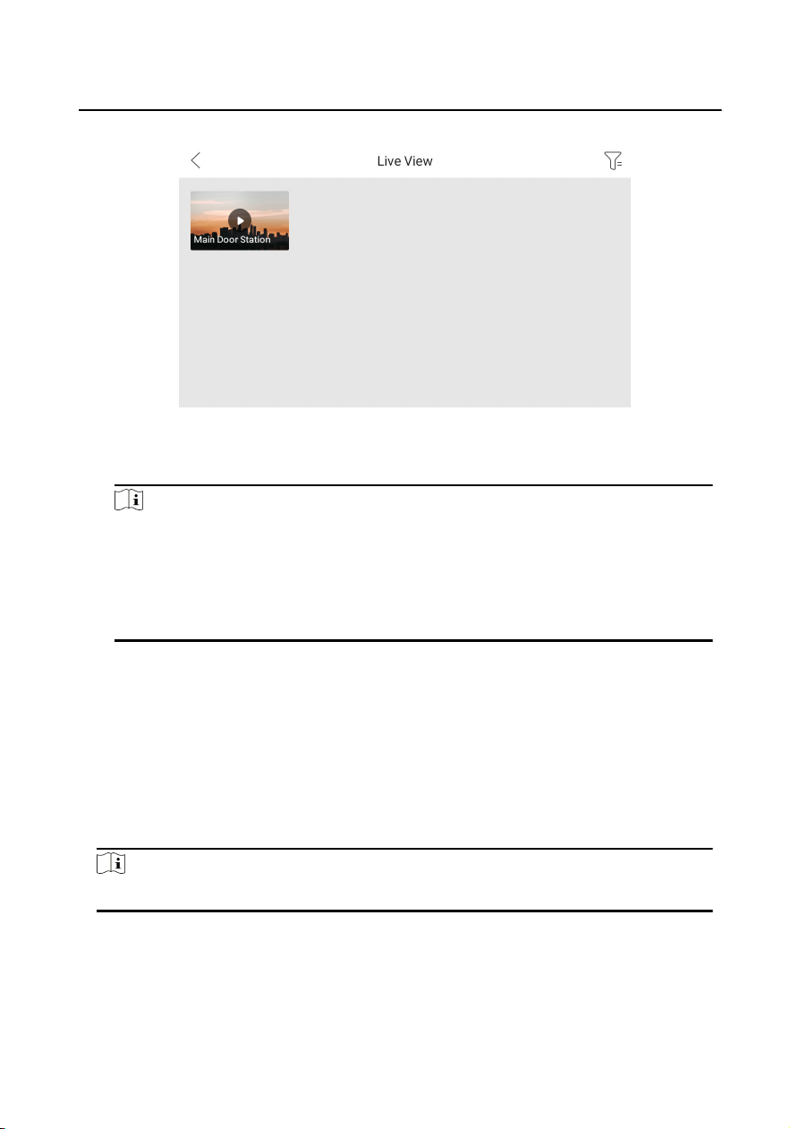
Figure 4-6 Live View
2. Tap Main Door
Staon to enter the live view page of door staon.
Note
●
On the Call from Door Staon page, there are 2 unlock buons: Unlock 1, and
Unlock 2. When you tap Unlock 1, the building gate will open by default. When
you tap Unlock 2, the door staon connected door will open.
●
On the Call from Door Staon page, there are 1 capture buon. You can tap the
buon to capture the picture via door staon.
3. Tap Camera to enter the live view page of network cameras.
4.3 Arm/Disarm
The indoor staon has four kinds of scene modes: sleeping mode, stay mode, away
mode, and custom mode. You can arm or disarm your room in each scene mode
manually. The selected scene mode will be displayed on the main page of the indoor
staon.
Note
You should create an Arm/Disarm Password rst.
4.3.1 Arm Room
Select the arm mode to arm your room.
Video Intercom 9 Series Indoor
Staon Operaon Guide
12

Before You Start
●
Wake up the device. Refers to Wake Up the Device for details.
●
On the main page of the device, tap Sengs → Advanced Sengs to enable the
Zone Alarm funcons.
●
You should create an arm/disarm password. Please refers to
Operaon Password
Sengs for the details.
Steps
1. On the main page of the device, tap Stay to enter the scene page.
2. Select Stay, Away, Sleeping or Custom.
3. Enter the arm/disarm password to enable the scene.
4. Tap OK.
Note
You can also tap → Arm to enable the scene.
4.3.2 Disarm Your Room
Before You Start
Wake up the device. Refers to Wake Up the Device for details.
Steps
1.
On the main page of the device, tap
→ Disarm to disarm.
2. Enter the arm/disarm password.
3. Tap OK.
4.4 Arming Mode
Sengs
4 arming modes can be congured: stay mode, away mode, sleeping mode and
custom mode.
Before You Start
Wake up the device. Refers to Wake Up the Device for details.
Tap Sengs → Advanced Sengs to enable Zone Alarm funcons.
Note
Admin password is required to enter the advanced sengs page.
Video Intercom 9 Series Indoor Staon Operaon Guide
13
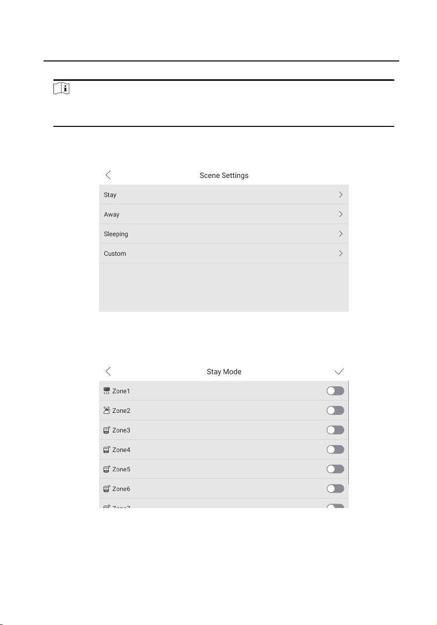
Steps
Note
Arming status page and zone sengs page are hidden by default. You should enable
alarm funcon rst.
1. On the main page of the device, tap Sengs → Preference → Scene Sengs to
enter the arming mode
sengs page.
Figure 4-7 Scene Sengs
2. Tap Stay, Away, Sleeping, or Custom to enter the page.
Figure 4-8 Arming Mode Sengs
3. Arm the selected zone.
Video Intercom 9 Series Indoor
Staon Operaon Guide
14
Note
●
Zones are congurable on the arming mode page.
●
24H alarm zone including smoke detector zone, gas detector zone and doorbell
zone will be triggered even if they are disabled.
●
When the doorbell zone is triggered, the device will ring but not upload the
alarm signal.
●
Arming mode sengs should be congured with the sengs of arming status
on the user page of the device.
4.5 Informaon Management
You can view public noce, visitor message, alarm log and capture log on
informaon management page.
Wake up the device. Refers to
Wake Up the Device for details.
Note
Indoor extension only supports alarm log and capture log.
Noce
On the main page of the device, tap or slide down the page to enter the
call informaon page. Tap Search Noce to enter the noce details page.
You can view the noce locally or that from mobile client.
Video Intercom 9 Series Indoor
Staon Operaon Guide
15
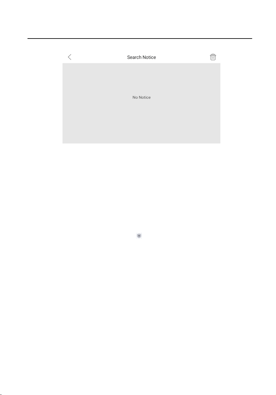
Figure 4-9 Search Noce
Details
Tap the item to view the details of the
noce.
Delete
Tap delete buon at the upper-right corner of the page and select items
to delete. Or slide the item to the le to delete the item only.
Alarm Log
On the main page of the device, tap or slide down to enter the alarm
informaon page. Tap Alarm Log to view the alarm logs.
Video Intercom 9 Series Indoor
Staon Operaon Guide
16
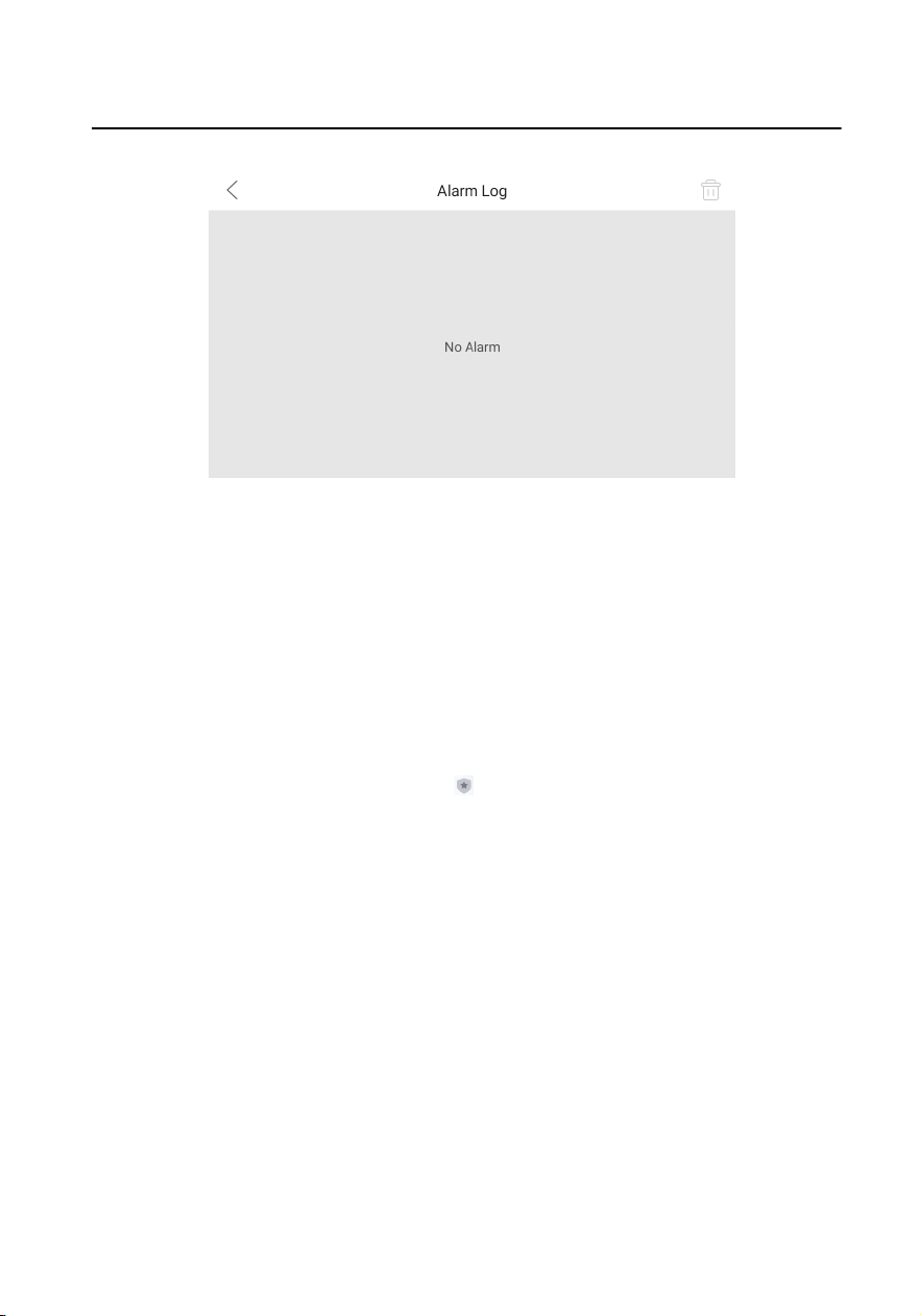
Figure 4-10 Alarm Logs
Details
Tap the item to view the details of the alarm log.
Delete
Tap delete buon at the upper-right corner of the page and select items
to delete. Or slide the item to the le to delete the item only.
Album
On the main page fo the device, tap or slide down to enter the alarm
informaon page. Tap Album to view the captures and images of the device.
Zoom In
Tap the item to zoom in the picture.
Delete
Tap delete
buon at the upper-right corner of the page and select
pictures to delete. Or slide the item to the le to delete the item only.
Delete Captures and Messages Automacally
On the main page of the device, tap Sengs → Basic Sengs to enter
the sengs page.
Video Intercom 9 Series Indoor
Staon Operaon Guide
17
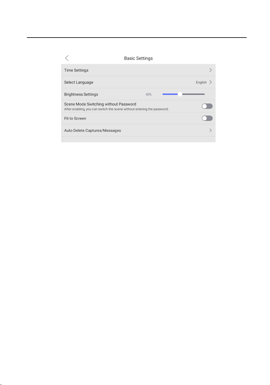
Figure 4-11 Basic Sengs
Tap Auto Delete Captures/Messages to set the interval to delete
automacally.
Video Intercom 9 Series Indoor
Staon Operaon Guide
18
5 Remote Operaon via Mobile Client
5.1 Set up Mobile Client
You can congure and operate the device via mobile client remotely.
Before You Start
Make sure your mobile device has been connected to Wi-Fi.
Steps
1. Install Hik-Connect and register a user account for iOS and Android.
1)
Search Hik-Connect in App Store
or
TM
to download and install the mobile
client.
2) Launch the mobile client and follow the on-screen instrucons to register a user
account.
2. Start the mobile client, and log in to the mobile client.
5.2 Set Up Device via Mobile Client
To operate the indoor staon normally, you should add the device to the client.
Steps
1. On the home page of the client, tap Add Device.
-
Scan QR code of the device to add.
Note
●
The QR code is printed on the label, which is on the rear panel of doorbell. If
you have already installed the device, you can scan the QR code on the cloud
service page in the device.
●
Tap
to enable the ashlight if the scanning environment is too dark.
-
If there are device QR codes in photo album of the phone, tap
to extract QR
code from local album.
-
If the system fails to recognize the QR code, tap and enter the serial No. to
add the device manually.
2. Connect to the network.
Video Intercom 9 Series Indoor
Staon Operaon Guide
19
Note
Make sure the device and the mobile device are in the same LAN.
-
Wired Connecon:
a. Tap Next.
b. Connect the device to the router with a network cable.
Note
Make sure your mobile phone is connected to the same router.
c. Tap Connected.
-
Wireless
Connecon:
a. Connect the device to the Wi-Fi.
Note
Make sure your mobile phone has been connected to the same Wi-Fi or your
device has been connected to the hotspot of the mobile phone.
b. Tap Add.
c. When the client displays Adding Completed, tap Next and edit the device
name to save.
5.3 Remote
Operaon
You can realize some certain funcons of the indoor staon via Hik-Connect
(including, but not limited to, live view via linked device, and edit device name).
Live View
Tap the indoor staon in the list to enter the Live View page. You can
monitor the linked door staon and linked camera.
Tap ... → Linked Camera to view the status of all cameras.
View and Edit Informaons
Tap ..., you can edit the device name.
You can tap ... to view the device verison.
Tap Delete Device to remove the device from the list.
Video Intercom 9 Series Indoor
Staon Operaon Guide
20
6 Remote Operaon via the client
soware
The Video Intercom module provides remote control and conguraon on video
intercom products via the iVMS-4200 client
soware.
6.1 Call Indoor Staon
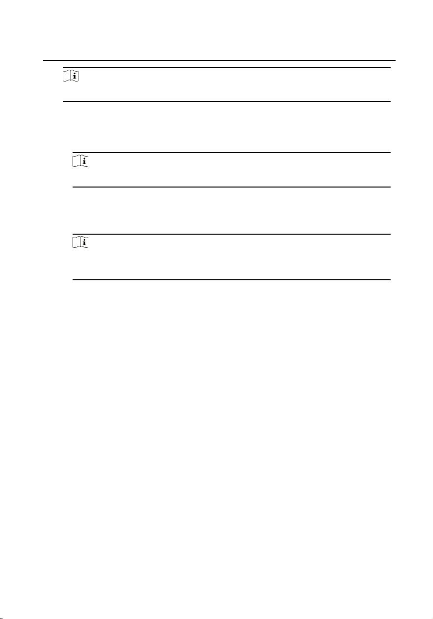
Steps
1. On the main page, click Access Control → Video Intercom to enter the Video
Intercom page.
2.
Select a resident and click in the Call Household column to start calling the
selected resident.
Figure 6-1 Calling Indoor Staon
3. Aer answered, you will enter the In Call window.
●
Click to adjust the volume of the loudspeaker.
●
Click Hang Up to hang up.
●
Click
to adjust the volume of the microphone.
Note
●
One indoor staon can only connect with one client soware.
●
You can set the maximum ring duraon ranging from 15s to 60s, and the
maximum speaking duraon ranging from 120s to 600s via the Remote
Conguraon of indoor staon.
Video Intercom 9 Series Indoor Staon Operaon Guide
21
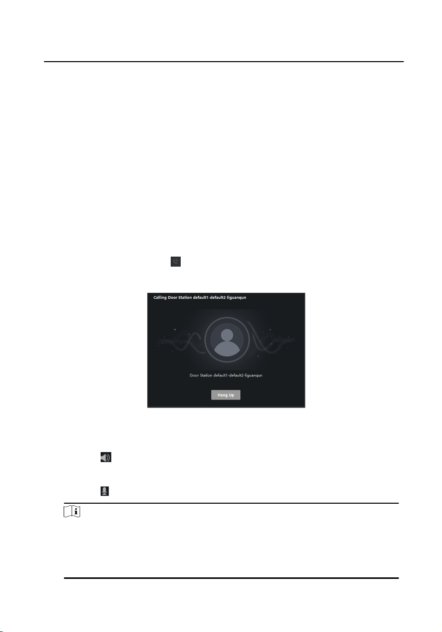
6.2 Receive Call from Indoor Staon/Door Staon
Steps
1. Select the client soware in the indoor staon or door staon page to start calling
the client and an incoming call dialog will pop up in the client
soware.
Figure 6-2 Incoming Call from Indoor Staon
2. Click Answer to answer the call. Or click Hang Up to decline the call.
3.
Aer you answer the call, you will enter the In Call window.
●
Click to adjust the volume of the loudspeaker.
●
Click Hang Up to hang up.
●
Click to adjust the volume of the microphone.
●
For door staon, you can click to open the door remotely.
Note
●
One video intercom device can only connect with one client soware.
●
The maximum ring duraon can be set from 15s to 60s via the Remote
Conguraon of the video intercom device.
●
The maximum speaking duraon between indoor staon and client can be set
from 120s to 600s via the Remote Conguraon of indoor staon.
●
The maximum speaking duraon between door staon and client can be set
from 90s to 120s via the Remote
Conguraon of door staon.
6.3 View Live Video of Door Staon and Outer Door
Staon
Video Intercom 9 Series Indoor Staon Operaon Guide
22
You can get the live view of the door staon and outer door staon in the Main View
module and control the door staon and outer door staon remotely.
In the Main View module, double-click a door staon or outer door staon device or
drag the device to a display window to start the live view.
You can click Unlock on the menu to open the door remotely.
6.4 View Call Logs
You can check all the call logs, including dialed call logs, received call logs and missed
call logs. You can also directly dial via the log list and clear the logs.
Steps
1. On the main page, click Access Control → Video Intercom to enter the Video
Intercom page.
2. Click the Call Log tab to enter the Call Log page. All the call logs will display on this
page and you can check the log informaon, e.g., call status, start me, resident's
organizaon and name, device name and ring or speaking duraon.
Figure 6-3 Call Log
3.
Oponal: Click the icon in the Operaon column to re-dial the resident.
6.5 Release
Noce
Video Intercom 9 Series Indoor Staon Operaon Guide
23
You can create dierent types of noces and send them to the residents. Four noce
types are available, including Adversing, Property, Alarm and Noce Informaon.
Steps
1. On the main page, click Access Control → Video Intercom to enter the Video
Intercom page.
2. Click
Noce to enter the Release Noce page.
Figure 6-4 Release Noce
3. Click Add on the le panel to create a new noce.
Video Intercom 9 Series Indoor
Staon Operaon Guide
24
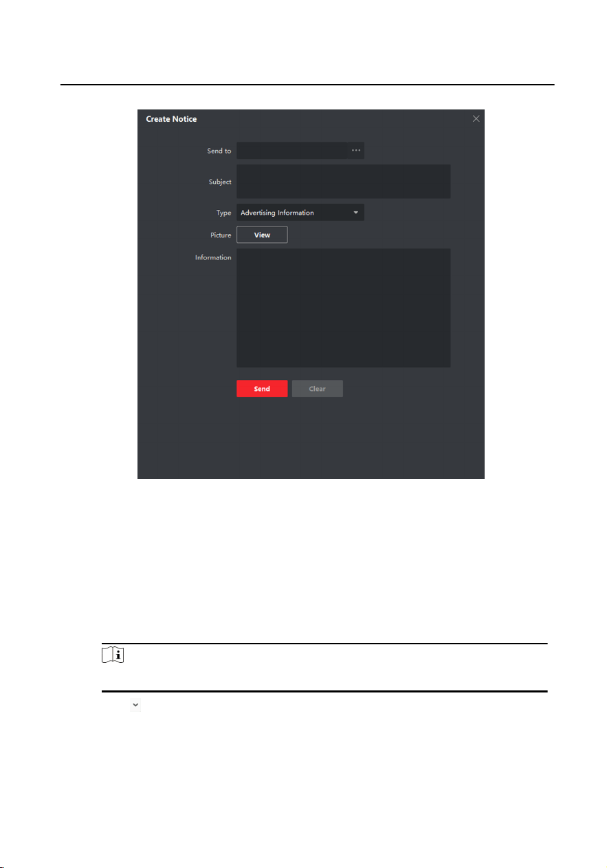
Figure 6-5 Create a Noce
4. Edit the noce on the right panel.
1) Click ... on the Send To eld to pop up the Select Resident dialog.
2) Check the checkbox(es) to select the resident(s). Or you can check the All
checkbox to select all the added residents.
3) Click OK to save the selecon.
4) Enter the subject on the Subject eld.
Note
Up to 63 characters are allowed in the Subject eld.
5)
Click
in the Type eld to unfold the drop-down list and select the noce type.
6)
Oponal: Click View to add a local picture to the noce.
Video Intercom 9 Series Indoor
Staon Operaon Guide
25

Note
Up to 6 pictures in the JPGE format can be added to one noce. And the
maximum size of one picture is 512KB.
7) Enter the noce content in the Informaon eld.
8) Oponal: You can also click Clear to clear the edited content.
Note
Up to 1023 characters are allowed in the Content eld.
5. Click Send to send the edited noce to the selected resident(s). The sent noce
informaon will display on the le panel. You can click a noce to view the details
on the right panel.
6.6 Search Video Intercom Informaon
You can search the call logs between the iVMS-4200 client soware and video
intercom devices, device unlocking logs and the sent
noce informaon.
On the main page, click Access Control to enter the access control module.
In the Access Control module, click Video Intercom to enter the Video Intercom
page.
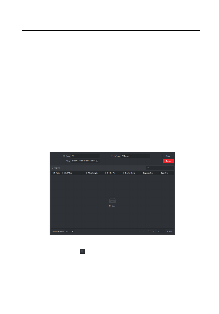
6.6.1 Search Call Logs
Steps
1. On the main page, click Access Control → Video Intercom to enter the Video
Intercom page.
2. Click Call Log to enter the Call Log page.
Video Intercom 9 Series Indoor
Staon Operaon Guide
26
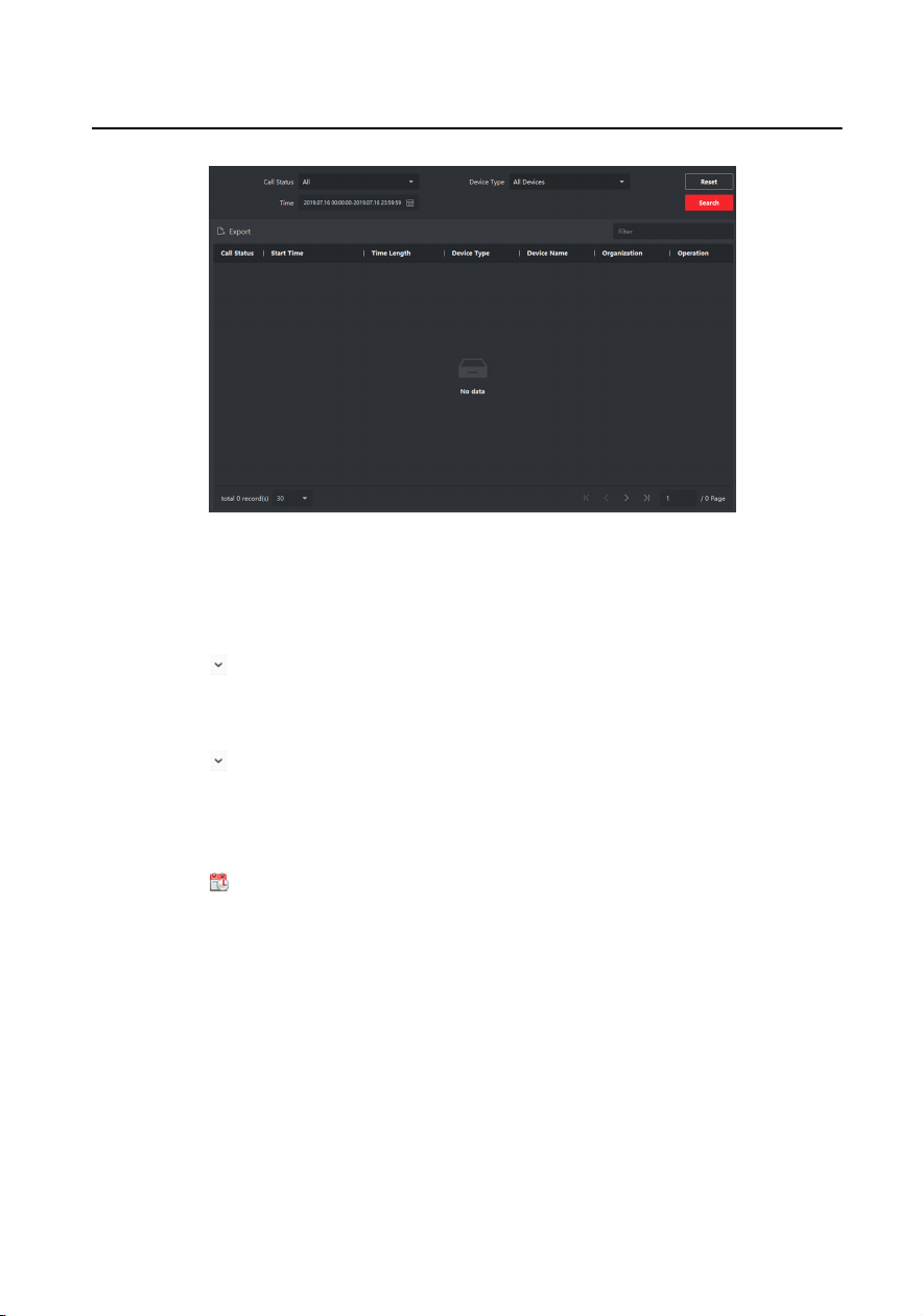
Figure 6-6 Search Call Logs
3. Set the search
condions, including call status, device type, start me and end
me.
Call Status
Click to unfold the drop-down list and select the call status as Dialed,
Received or Missed. Or select All to search logs with all statuses.
Device Type
Click to unfold the drop-down list and select the device type as Indoor
Staon, Door Staon, Outer Door Staon or Analog Indoor Staon. Or select
All Devices to search logs with all device types.
Start Time/End Time
Click to specify the start me and end me of a me period to search the
logs.
4.
Oponal: You can click Reset to reset all the congured search condions.
5. Click Search and all the matched call logs will display on this page.
●
Check the detailed informaon of searched call logs, such as call status, ring/
speaking duraon, device name, resident organizaon, etc.
●
Input keywords in the Search
eld to lter the desired log.
●
Click Export to export the call logs to your PC.
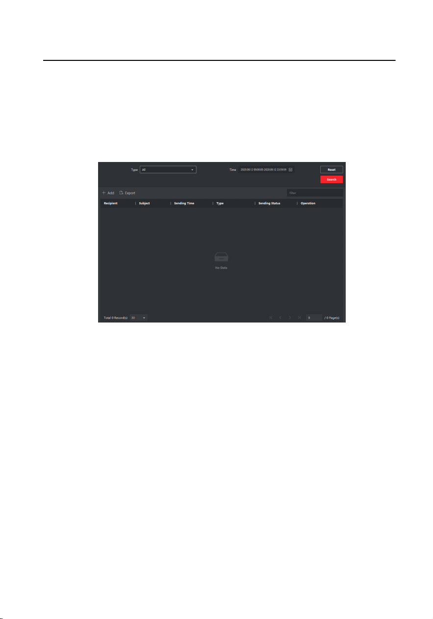
6.6.2 Search
Noce
Video Intercom 9 Series Indoor Staon Operaon Guide
27
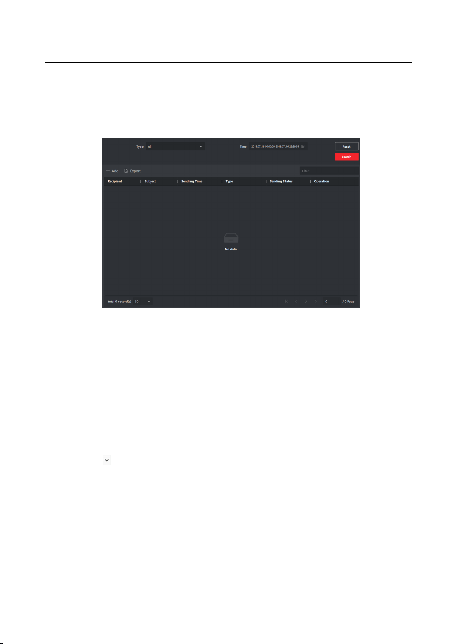
Steps
1. On the main page, click Access Control → Video Intercom to enter the Video
Intercom page.
2. Click Noce to enter the Noce page.
Figure 6-7 Search Noce
3. Set the search condions, including noce type, subject, recipient, start me and
end me.
Recipient
Input the recipient
informaon in the Recipient eld to search the specied
noce.
Subject
Input the keywords in the Subject eld to search the matched noce.
Type
Click to unfold the drop-down list and select the noce type as Adversing
Informaon, Property Informaon, Alarm Informaon or Noce
Informaon
. Or select All to search noces with all types.
4.
Oponal: You can click Reset to reset all the congured search condions.
5. Click Search and all the matched noces will display on this page.
●
Check the detailed
informaon of searched noces, such as sending me,
sending status, etc.
●
Input keywords in the Search
eld to lter the searching result.
Video Intercom 9 Series Indoor
Staon Operaon Guide
28

6. You can view and edit the noce details, check the sending failed/sent succeeded/
unread users, and resend the noce to sending failed/unread users.
7. Oponal: Click Export to export the noces to your PC.
Video Intercom 9 Series Indoor Staon Operaon Guide
29
A. Communicaon Matrix and Device
Command
Communicaon Matrix
Scan the following QR code to get the device communicaon matrix.
Note that the matrix contains all communicaon ports of Hikvision access
control and video intercom devices.
Figure A-1 QR Code of Communicaon Matrix
Device Command
Scan the following QR code to get the device common serial port
commands.
Note that the command list contains all commonly used serial ports
commands for all Hikvision access control and video intercom devices.
Figure A-2 Device Command
Video Intercom 9 Series Indoor Staon Operaon Guide
30

UD27308B