Loading ...
Loading ...
Loading ...
16
Refrigerant
pipes
Bucket
Portable pump
Air outlet
Drain outlet
Installation and Maintenance
CAUTION
Drain piping passing indoors
Drain sockets.
Referring the figure below, insulate the drain socket
and drain hose.
Drain piping connections
Do not connect the drain pipes directly to sewage pipes
to avoid ammonia odor. The ammonia in the sewage
might enter the indoor unit through the drain pipes
and corrode the heat exchanger.
Do not twist or bend the drain hose, doing so applies
excessive force applied on it and may also cause
leakage.
After piping work is finished, check if drainage flows
smoothly.
Gradually pour approximately 1000 cc of water from
the outlet hole into the drain pan to check drainage flow.
Check the drainage as shown below:
Drain hose
Sealing material Sealing material
●
●
●
●
●
●
●
If the fuses blow, please call the authorized service dealer.
Please do not replace it by yourself, as it may result in
accident or electric shock.
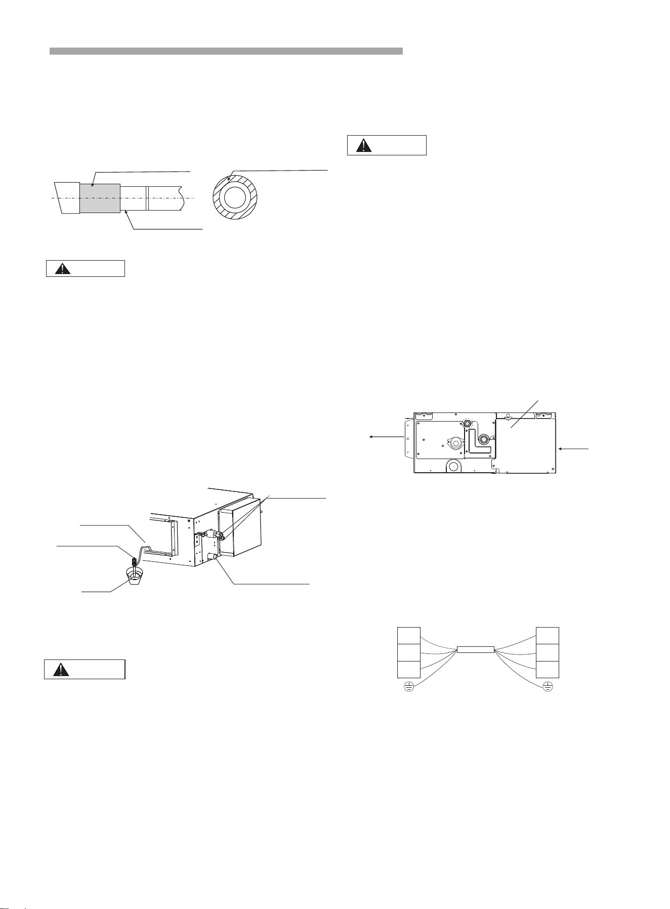
(1) As shown in Fig. 6.1, remove the screws on the
control box.
(2) Connect the power cord and ground wire to the main
terminal.
(3) Connect the remote control wire to the subsidiary
terminal box.
(4) Connect the power supply of the indoor and outdoor
units to the main terminal.
(5) Tie the wire in the control box with the clamp tightly.
(6) After completing the wiring, seal the wiring hole with
the sealing material (with the lid) to prevent the
condensation and insects entering the control box.
WARNING
6. Electrical Wiring
least 50 mm so that they do not pass through the same
place together. Proximity may cause electrical
interference malfunction and breakage.
When clamping the wiring, use the included clamping
material as shown in Fig.6.1 to prevent external
pressure being exerted on the wiring connections and
clamp firmly.
While performing wiring work, make sure the wiring
is proper and does not cause the control box lid to
stick up, then close the cover firmly. When attaching
the control lid, make sure you do not pinch any wires.
Outside the indoor unit and outdoor unit, separate the
weak wiring (remote controller and transmission wiring)
and strong wiring (ground and power supply wiring) at
CAUTION
6.1 General Check
●
●
●
Remove the screws on the control box
Fig.6.1
Electrical Wiring Diagram
Outdoor unit
Indoor unit
Terminal
Terminal
4(SI)
SI
1(L)
L
2(N)
N
Transmitting cable
The lid of the control box
Air inlet
Air outlet
Loading ...
Loading ...
Loading ...