Loading ...
Loading ...
Loading ...

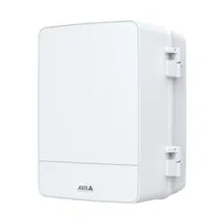
AXISA1214NetworkDoorControllerKit
Specifications
Auxiliaryconnector
Usetheauxiliaryconnectorwithexternaldevicesincombinationwith,forexample,motiondetection,eventtriggering,andalarm
notications.Inadditiontothe0VDCreferencepointandpower(DCoutput),theauxiliaryconnectorprovidestheinterfaceto:
Digitalinput-Forconnectingdevicesthatcantogglebetweenanopenandclosedcircuit,forexamplePIRsensors,door/window
contacts,andglassbreakdetectors.
Supervisedinput-Enablespossibilitytodetecttamperingonadigitalinput.
Digitaloutput-ForconnectingexternaldevicessuchasrelaysandLEDs.ConnecteddevicescanbeactivatedbytheVAPIX®
ApplicationProgrammingInterfaceorfromtheproduct’swebpage.
4-pinterminalblock
FunctionPinNotes
Specications
DCground
1
0VDC
DCoutput
2
Canbeusedtopowerauxiliaryequipment.
Note:Thispincanonlybeusedaspowerout.
12VDC
Maxload=50mAintotal
Digitalinputorsupervisedinput–Connecttopin1toactivate,or
leaveoating(unconnected)todeactivate.Tousesupervisedinput,
installend-of-lineresistors.Seeconnectiondiagramforinformation
abouthowtoconnecttheresistors.
0tomax30VDC Congurable
(InputorOutput)
3–4
Digitaloutput–Internallyconnectedtopin1(DCground)when
active,andoating(unconnected)wheninactive.Ifusedwithan
inductiveload,e.g.,arelay,connectadiodeinparallelwiththe
load,toprotectagainstvoltagetransients.EachI/Oiscapableof
driving12VDC,50mA(max)externalload,ifinternal12VDC
output(pin2)isused.Inthecaseofusingopendrainconnections
incombinationwithanexternalpowersupply,thentheI/Oscan
manageDCsupplyof0–30VDC,100mA.
0tomax30VDC,opendrain,
100mA
1
DCground
2
DCoutput12V
3
I/Oconguredasinput
4
I/Oconguredasoutput
Externalconnector
Two2-pinterminalblocksforexternaldevices,forexampleglassbreakorredetectors.
28
Loading ...
Loading ...
Loading ...
