Loading ...
Loading ...
Loading ...
AXISA1214NetworkDoorControllerKit
Specifications
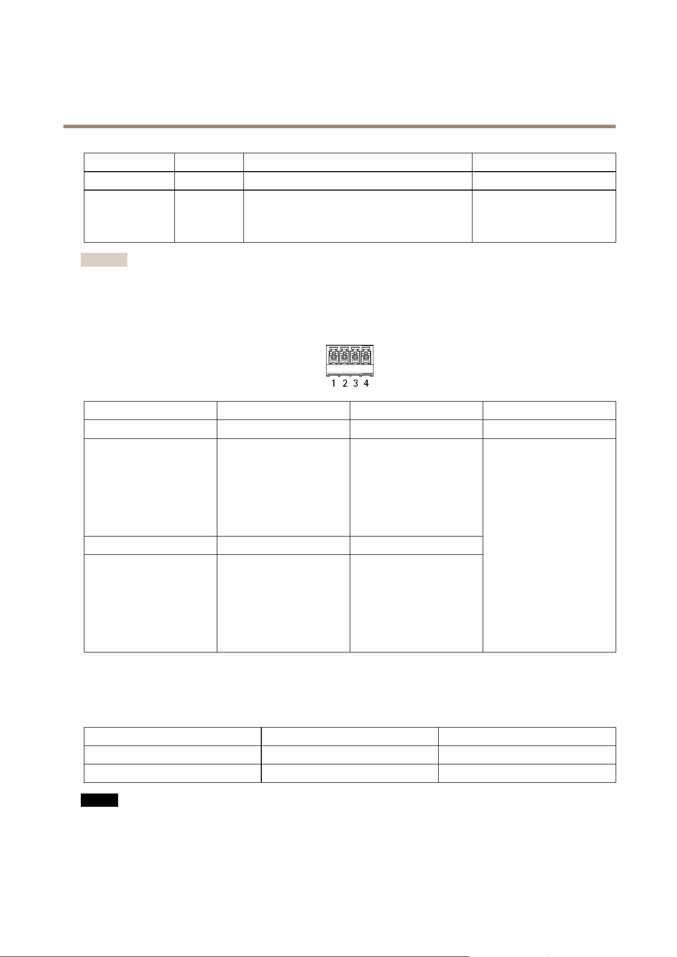
FunctionPinNotes
Specications
DCground
1,3
0VDC
Input
2,4
Forcommunicatingwithdoormonitor.
DigitalinputorSupervisedinput—Connectto
pin1or3respectivelytoactivate,orleaveoating
(unconnected)todeactivate.
0tomax30VDC
Important
Thequaliedcablelengthisupto200m(656ft)ifthefollowingcablerequirementismet:AWG24.
Relayconnector
One4-pinterminalblockforformCrelaysthatcanbeused,forexample,tocontrolalockoraninterfacetoagate.
FunctionPinNotes
Specications
DCground(GND)
1
0VDC
NO
2
Normallyopen.
Forconnectingrelaydevices.
Connectafail-securelock
betweenNOandDCground.
Thetworelaypinsare
galvanicallyseparatedfrom
therestofthecircuitryifthe
jumpersarenotused.
COM
3
Common
NC
4
Normallyclosed.
Forconnectingrelaydevices.
Connectafail-safelock
betweenNCandDCground.
Thetworelaypinsare
galvanicallyseparatedfrom
therestofthecircuitryifthe
jumpersarenotused.
Maxcurrent=2A
Maxvoltage=30VDC
Relaypowerjumper
Whentherelaypowerjumperistted,itconnects12VDCor24VDCtotherelayCOMpin.
ItcanbeusedtoconnectalockbetweentheGNDandNO,orGNDandNCpins.
Powersource
Maxpowerat12VDCMaxpowerat24VDC
DCIN
1600mA800mA
PoE900mA450mA
NO NO
NO
TICE TICE
TICE
Ifthelockisnon-polarized,werecommendyoutoaddanexternalybackdiode.
27
Loading ...
Loading ...
Loading ...