Distributed by:
Perfect Aire, LLC
5401 Dansher Rd.
Countryside, IL 60525
844-4PA-AIRE | 844-472-2473
www.perfectaire.us
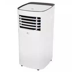
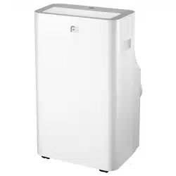
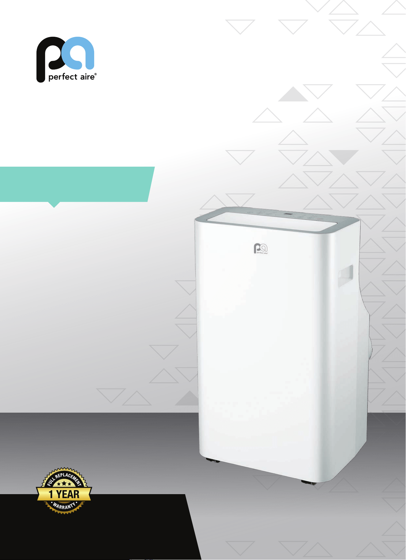
PORTABLE
AIR CONDITIONER
FOR MODEL:
PORTQ12000
Before using your air conditioner, please
read this manual carefully and keep it for
future reference, along with your receipt.
Specification and performance data is subject to change without notice.
Printed in China
PA/User_PORTQ12000/03302018
USER MANUAL

For your own records, please attach a copy of your sales receipt to this manual and complete the following:
Model Number:
_____________________________________ Serial Number: _______________________________________
Purchase Date: ____________________________________ Store Purchased: _____________________________________
Installation Date: ___________________________________ Installation Co.: _______________________________________
Installer Name:
_____________________________________ Installer Phone No.: ___________________________________
CONSUMER PRODUCT INFORMATION
SAFETY PRECAUTIONS ...................................................................1
IDENTIFICATION OF PARTS
...........................................................3
INSTALLATION INSTRUCTIONS
.....................................................5
CARE AND MAINTENANCE
............................................................10
AIR CONDITIONER FEATURES
.......................................................11
OPERATING INSTRUCTIONS
..........................................................12
TROUBLESHOOTING
.......................................................................14
CONTENTS
This manual provides the information needed for proper use and maintenance
of this air conditioner. Basic preventative care can help extend the life of this
unit. The “Troubleshooting” section in this manual contains a chart with
solutions to the most common problems. Referring to this section may save
time and prevent the need for a service call in the event of a problem.
NOTE: The rating data indicated on the energy label is based on the testing condition of installing the
un-extended air exhaust duct without at mouth, round mouth, and wall exhaust adapters. (The duct
and the adapters are listed in the accessories chart of this Instruction Manual.)
ENERGY SAVING TIPS
• Use the unit in the recommended room size.
• Locate the unit where furniture cannot obstruct the air ow.
• Keep blinds/curtains closed during the sunniest part of the day (cooling mode).
• Keep the lters clean.
• Keep doors and windows closed to keep cool air in and warm air out (cooling mode) or keep warm air in and cool air
out (heating mode for units with heat function).
NOTE: All the illustrations in this manual are for explanation purposes only. Unit purchased may be slightly dierent.
The design and specications are subject to change without prior notice for product improvement. Contact Consumer
Services at 844-472-2473 for details.
OPERATING CONDITIONS
The air conditioner must be operated within the temperature range indicated below:
MODE ROOM TEMPERATURE
COOL
62°F (17°C) – 95°F (35°C)
DRY 55°F (13°C) – 95°F (35°C)
HEAT ≥86°F (30°C)
NOTE: Performance may be
reduced outside of these
operating temperatures.
1
WARNING
DO NOT store or use gasoline or other ammable vapors and liquids in the vicinity of this or any other appliance.
DO NOT use an extension cord or an adapter plug; avoid re hazard or electric shock. Do not remove any prong
from the power cord..
Be sure the electrical service is adequate for the model you have chosen. This information can be found on the
serial plate, which is located on the side of the cabinet and behind the grille.
Be sure the air conditioner is properly grounded. To minimize shock or re hazards, proper grounding is import-
ant. The power cord is equipped with a three-prong grounding plug for protection against shock hazards.
Your air conditioner must be used in a properly grounded wall receptacle. If the wall receptacle you intend to
use is not adequately grounded or protected by a time delay fuse or circuit breaker, have a qualied electrician
install the proper receptacle.
Ensure the receptacle is accessible after the unit installation.
READ SAFETY PRECAUTIONS BEFORE INSTALLATION
To prevent injury to the user or other people and property damage, the following instructions must be followed.
Incorrect operation due to ignoring of instructions may cause harm or damage.
NEVER DO THIS. ALWAYS DO THIS.
SAFETY PRECAUTIONS
CAUTION
• Contact a qualied installer for installation of this unit if necessary.
• Contact a qualied service technician for repair or maintenance of this unit.
• The air conditioner is not intended for use by young children without supervision. Young children should be supervised
to ensure that they do not play with the air conditioner.
• If the power cord is to be replaced, replacement work should be performed by authorized personnel only.
• Installation and repair work must be performed in accordance with the national wiring standards by authorized
personnel only.
• DO NOT operate your air conditioner in a wet room such as a bathroom or laundry room.
• This appliance can be used by persons with reduced physical, sensory or mental capabilities or lack of experience
and knowledge if they have been given supervision or instruction concerning use of the appliance in a safe way and
understand the hazards involved. Cleaning and user maintenance shall not be made by children without supervision.
• Children should be supervised to ensure that they do not play with the appliance.
• Disabled persons may require assistance with setup and/or use.
• DO NOT operate the appliance with a damaged cord or plug. Call Consumer Services at 844-472-2473 if the power
supply cord and/or plug is damaged; it must be replaced by a qualied service technician in order to avoid a hazard.
• Prior to cleaning or other maintenance, the appliance must be disconnected from its main power supply.
• DO NOT install the appliance in a location that may be exposed to combustible gas.
• If combustible gas (or other ammable liquids or vapors) accumulates around the unit, it may cause re.
• DO NOT run cord under carpeting. Do not cover cord with throw rugs, runners, or similar coverings. Do not route cord
under furniture or appliances. Arrange cord away from trac area and where it will not be tripped over.
• To reduce the risk of re or electric shock, do not use the appliance with any solid-state speed control device.
• The appliance shall be installed in accordance with national wiring regulations.
• When there are dierences between “USER MANUAL” and “Remote Control Manual” on function description, the
description on “USER MANUAL “ shall prevail.

2
SAFETY PRECAUTIONS
Please read through these instructions before you start the installation process. Improper installation can cause damage
to the unit, your personal property, and also poses a personal safety hazard.
• Installation must be performed according to the installation instructions. Improper installation can cause water
leakage, electrical shock, or re.
• Use only the included accessories and parts, and specied tools for the installation. Using non-standard parts can
cause water leakage, electrical shock, re, and injury or property damage.
• Make sure that the outlet you are using is grounded and has the appropriate voltage. The power cord is equipped
with a three-prong grounding plug to protect against shock. Voltage information can be found on the side of the unit,
behind the grille. If the wall receptacle you intend to use is not adequately grounded or protected by a time delay fuse
or circuit breaker, have a qualied electrician install the proper receptacle.
• Ensure the receptacle is accessible after the unit installation.
• Install the unit on a at, level, sturdy surface. Failure to do so could result in damage or excessive noise and vibration.
• The unit must be kept free from obstruction to ensure proper function and to mitigate safety hazards.
• DO NOT modify the length of the power cord or use an extension cord to power the unit.
• DO NOT share a single outlet with other electrical appliances. Improper power supply can cause re or electrical shock.
• DO NOT remove any prong from the power cord.
• DO NOT install your air conditioner in a wet room such as a bathroom or laundry room. Too much exposure to moisture
can cause electrical components to short circuit. Your air conditioner should be used in such a way that it is protected
from moisture (i.e. condensation, splashed water, etc.). Do not place your air conditioner where it can fall or be pulled
into water or any other liquid. If the unit does ever fall into water, unplug it immediately.
• DO NOT install the unit in a location that may be exposed to combustible gas or other ammable liquids or vapors as
this could cause re. Do not store or use gasoline or other ammable vapors and liquids in the vicinity of this or any
other appliance.
• The unit has wheels to facilitate moving. Make sure not to use the wheels on thick carpet or to roll over objects, as
these could cause tipping. Always transport your air conditioner in a vertical position and stand on a stable, level
surface during use.
• DO NOT operate a unit that has been dropped or damaged.
• DO NOT remove any xed covers from the unit.
• Only use the included accessories and specied parts for installation. Using nonstandard parts can cause water
leakage, electrical shock, re, and injury or property damage.
• The unit must be kept free from obstruction to ensure proper function. Keep an air path of at least 12 in (30 cm) all
around the unit from alls, furniture, and curtains.
• DO NOT allow children to play with the air conditioner. Children must be supervised around the unit at all times.
• If the air conditioner is knocked over during use, turn the unit o and unplug it from the main power supply
immediately. Visually inspect the unit to ensure there is no damage. If you suspect the unit has been damaged, contact
a technician or customer service for assistance.
• In a thunderstorm, unplug the air conditioner to avoid potential lightning damage.
• Turn o the air conditioner when not in use.
• DO NOT touch the unit or plug with wet or damp hands or when barefoot.
• DO NOT press the buttons on the control panel with anything other than your ngers.
• DO NOT remove any xed covers. Never use this appliance if it is not working properly or if it has been dropped
or damaged.
• NEVER use the plug to start or stop the unit. (Always use the switch on the control panel or remote to power the unit on
and o.)
• DO NOT use this product for functions other than those described in the instruction manual.
3
IDENTIFICATION OF PARTS
ACCESSORIES
Check that all the accessories are included in the package (Fig. 1) and refer to the installation instructions for their usage.
Your Window Installation Kit ts windows 26.5 – 48 inches (67.5 – 123 cm) and can be shortened for smaller windows.
TOOLS NEEDED:
• Medium Phillips screwdriver
• Tape measure or ruler
• Knife or scissors
• Saw (optional, to shorten window adapter for narrow windows)
PART DESCRIPTION QUANTITY
Unit Adapter 1 pc
Exhaust Hose 1 pc
Window slider Adapter 1 pc
Bolt 1 pc
Window Slider A 1 pc
Window Slider B 1 pc
Foam Seal A (Adhesive) 2 pcs
Foam Seal B (Adhesive) 2 pcs
Foam Seal C (Non-Adhesive) 1 pc
Security Bracket and 2 Screws 1 set
Drain Hose 1 pc
Power Cord Buckle 1 pc
ON/OF F
TEMP
S HO R T
C U T
TI ME R
O N
TI ME R
O F F
MO DE
FA N
S LE E P
S WI NG
LE D
Remote Control and Batteries 1 set
NOTE: All of the illustrations in this manual are for explanation purposes only. Your air conditioner may be slightly dierent.
FIG. 1
ABOUT FLUORINATED GASES
• This air conditioning unit is a hermetically sealed unit that contains fluorinated gases. For specific
information on the type of gas and the amount, please refer to the relevant label on the unit itself.
• Installation, service, maintenance and repair of this unit must be performed by a certified technician.
• Product uninstallation and recycling must be performed by a certified technician.
• When the unit is checked for leaks, proper record-keeping of all checks is strongly recommended.
4
PARTS DIAGRAMS
REAR
OPERATION OF CURRENT DEVICE
FRONT
FIG. 2
1
3
2
4
FIG. 3
11
12
14
13
5
6
8
9
10
7
1. Control Panel
2. Horizontal Louver Blade
3. Handle (both sides)
4. Caster
5. Upper Air Filter (behind the grille)
6. Upper Air Intake
7. Drain Outlet
8. Air Outlet
9. Lower Air Filter
10. Lower Air Intake
11. Power Plug Socket (used
only when storing the unit)
12. Power Cord Buckle
13. Power Cord Outlet
14. Bottom Tray Drain Outlet
TEST
RESET
FIG. 4
The power supply cord contains a current device that senses damage to the power
cord. To test your power supply cord do the following:
1. Plug in the air conditioner.
2. The power supply cord will have TWO buttons on the plug head. Press the TEST
button. The RESET button will click as it pops out.
3. Press the RESET button; again you will notice a click as the button engages.
4. The power supply cord is now supplying electricity to the unit. (On some
products this is also indicated by a light on the plug head.)
NOTES:
• Do not use this device to turn the unit on or o.
• Always make sure the RESET button is pushed in for correct operation.
• The power supply must be replaced if it fails to reset when either the TEST
button is pushed or it cannot be reset.
• If power supply cord is damaged, it cannot be repaired. Please call Consumer
Services at 844-472-2473.
NOTE: Some plugs have buttons
on top.
5
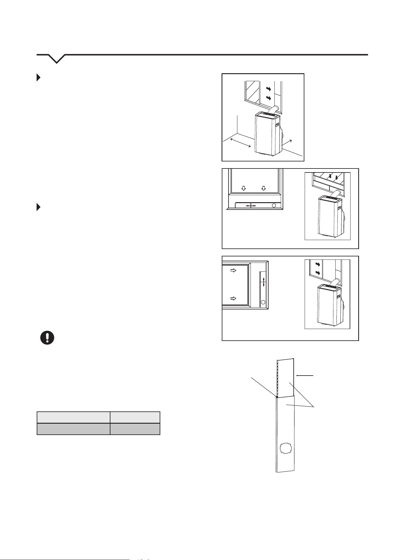
INSTALLATION INSTRUCTIONS
LOCATION
• The air conditioner should be placed on a firm
surface to minimize noise and vibration. For
safe and secure positioning, place the unit on a
smooth, level floor strong enough to support
the unit.
• The unit has casters to aid placement, but it
should only be rolled on smooth, flat surfaces. Use
caution when rolling on carpeted surfaces. Do not
attempt to roll the unit over objects.
• The unit must be placed within reach of a properly
rated ground socket.
• Never place any obstacles around the air inlet or
outlet of the unit.
• Allow 12 in. (30cm) to 40 in. (100cm) of space from
the wall for efficient air conditioning. (See Fig 5.)
WINDOW SLIDER KIT INSTALLATION
Your window slider kit has been designed to t
most standard “vertical” and “horizontal” window
applications. However, it may be necessary for you to
improvise or modify some aspects of the installation
procedures for certain types of windows. Please
refer to Fig. 6 and Fig. 7 for minimum and maximum
window openings. Window slider kit length can be
xed with a bolt. (See Fig. 8.)
NOTE: If the window opening is less than 2 ft., cut
the extension piece (See Fig. 8) shorter so the
kit properly ts in the window opening. Only cut
if absolutely necessary. Never cut the hole in the
window slider kit.
CAUTION
Make sure that there are no obstacles around the air
outlet of the exhaust hose (in the range of 20 in. / 50
cm) in order for the exhaust system to
work properly.
The exhaust hose and adapter must be installed
or removed in accordance with the usage mode as
indicated below:
COOL or AUTO mode Install Hose
FAN or DRY mode Remove Hose
FIG. 5
FIG. 7
FIG. 6
FIG. 8
A:12–40 in. B:≥12in.
Vertical
Window
Horizontal
Window
Extension
Piece
Window Slider Kit
Bolt
Window Slider Kit
Minimum: 2 ft. (67cm)
Maximum: 4 ft. (123 cm)
Window Slider Kit
Minimum: 2 ft. (67cm)
Maximum: 4 ft. (123 cm)
A
B
6
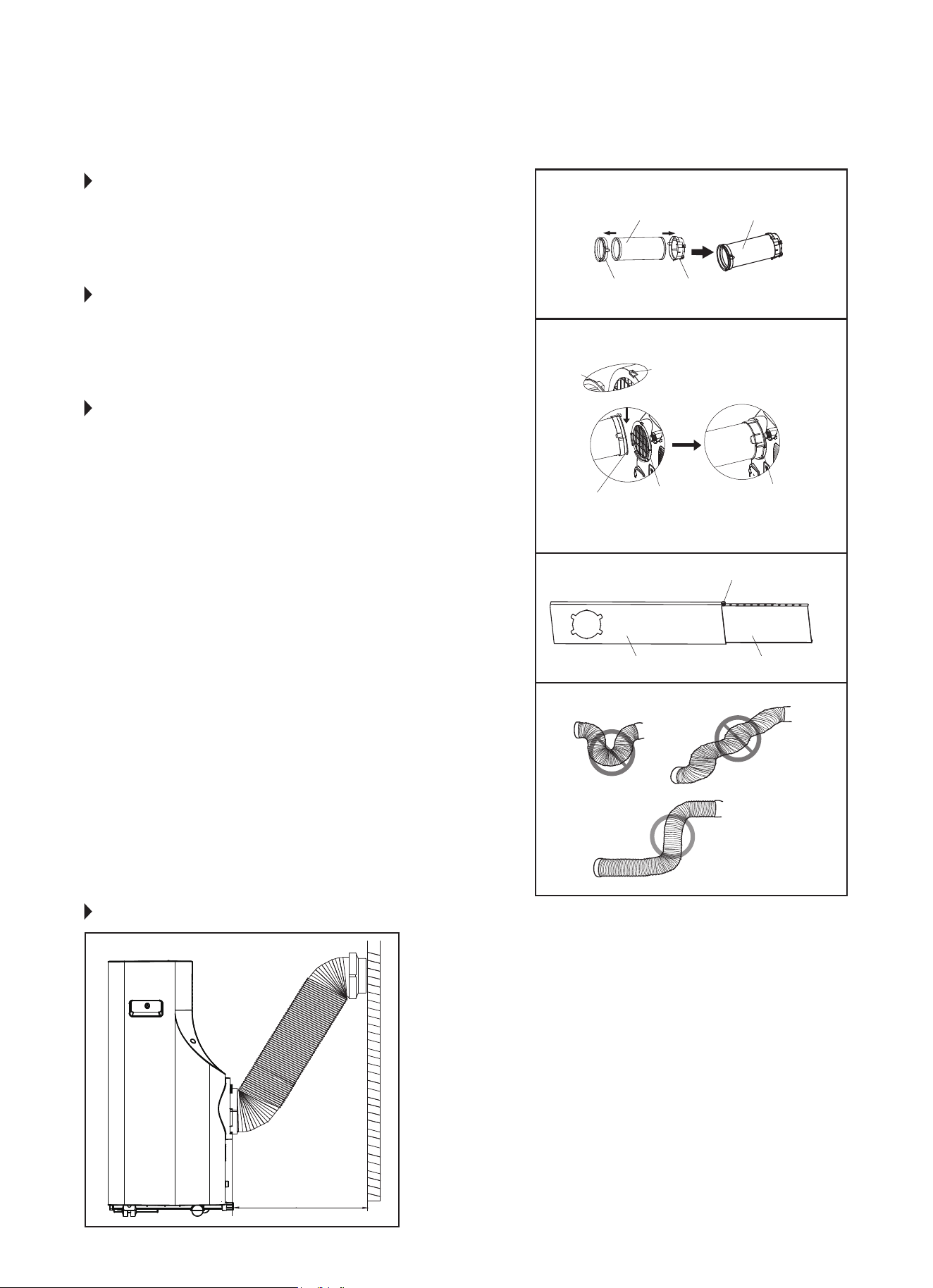
STEP 1:
PREPARING THE EXHAUST HOSE
ASSEMBLY
Fig. 9
Press the exhaust hose into the window slider adapter and
unit adapter; it will snap automatically to the adapters.
STEP 2:
INSTALL THE EXHAUST HOSE ASSEMBLY
TO THE UNIT
Fig. 10
Slide the Exhaust hose into the air outlet opening of the
unit along the arrow direction, from left to right.
STEP 3:
PREPARING THE ADJUSTABLE WINDOW
SLIDER
Fig. 11
a. Depending on the size of your window, adjust the size of
the window slider.
b. If the length of the window requires two window sliders,
use the bolt (included) to fasten the window sliders once
they are adjusted to the proper length.
NOTE: To ensure proper function, DO NOT overextend or
bend the hose. Make sure that there are no obstacles
around the air outlet of the exhaust hose (20 inch
clearance) in order to ensure the exhaust system works
properly. (Fig. 12.)
Once the Exhaust Hose assembly and Adjustable Window
Slider are prepared, choose from one of the following two
installation methods:
• Hung Window Installation (page 7)
• Sliding Window Installation (page 8)
FIG. 9
FIG. 10
FIG. 11
FIG. 12
Unit Adapter
Hook
Adapter
Bolt (if needed)
Window Slider A Window Slider B
Lower
Groove
Make sure the
adapter is inserted
into the lower groove
of the air outlet.
Notch
Window Slider
Adapter
Exhaust Hose Exhaust Hose Assembly
RECOMMENDED INSTALLATION
NOTE: All the illustrations in this manual are
for explanation purposes only. Your unit
may be slightly dierent. The actual shape
of the unit prevails.
The unit can be controlled by it’s control
panel or with the remote control. This
manual does not include remote control
operations. See the Remote Control User
Manual included with the unit for details.
20 inches
50 cm
7
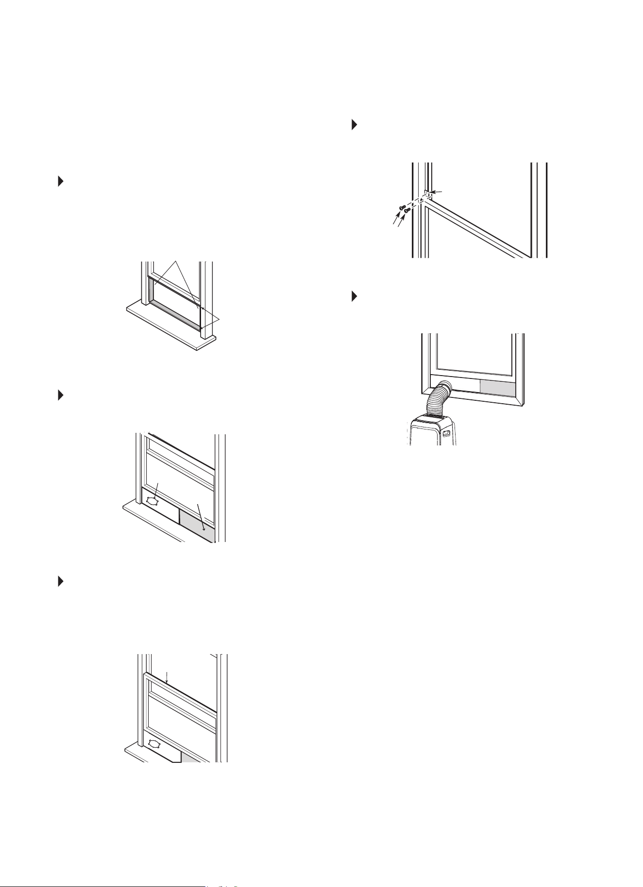
TYPE 1:
HUNG WINDOW INSTALLATION
STEP 1 Fig. 13.
Cut the adhesive foam seal A and B strips to the
proper lengths, and attach them to the window sash
and frame as shown.
STEP 2 Fig. 14.
Insert the window slider assembly into the window
opening.
STEP 3 Fig. 15.
Cut the non-adhesive foam seal C strip to match
the width of the window. Insert the seal between
the glass and the window frame to prevent air and
insects from getting into the room.
STEP 4 Fig. 16.
If desired, install the security bracket with 2 screws
as shown.
STEP 5 Fig. 17.
Insert the window slider adapter into the hole of the
window slider.
NOTE: All the illustrations in this manual are for
explanation purposes only. Your unit may be
slightly dierent.
Foam Seal B
(Adhesive type - shorter)
Foam Seal C
(Non-adhesive
type)
Window
Slider A
Window
Slider B
(if required)
Foam Seal A
(Adhesive type)
Security Bracket
FIG. 13
FIG. 14
FIG. 15
FIG. 16
FIG. 17
2 Screws
8
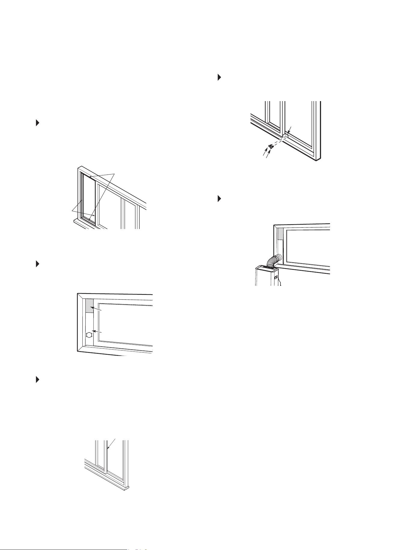
TYPE 2:
SLIDING WINDOW
INSTALLATION
STEP 1 Fig. 18.
Cut the adhesive foam seal A and B strips to the
proper lengths, and attach them to the window sash
and frame as shown.
STEP 2 Fig. 19.
Insert the window slider assembly into the window
opening.
STEP 3 Fig. 20.
Cut the non-adhesive foam seal C strip to match
the width of the window. Insert the seal between
the glass and the window frame to prevent air and
insects from getting into the room.
STEP 4 Fig. 21.
If desired, install the security bracket with 2 screws
as shown.
STEP 5 Fig. 22.
Insert the window slider adapter into the hole of the
window slider.
NOTE: All the illustrations in this manual are for
explanation purposes only. Your unit may be
slightly dierent.
FIG. 18
FIG. 19
FIG. 20
FIG. 21
FIG. 22
Foam Seal B
(Adhesive type - shorter)
Foam Seal A
(Adhesive type)
Foam Seal C
(Non-adhesive type)
Window
Slider A
Security
Bracket
2 Screws
Window
Slider B
(if required)
9
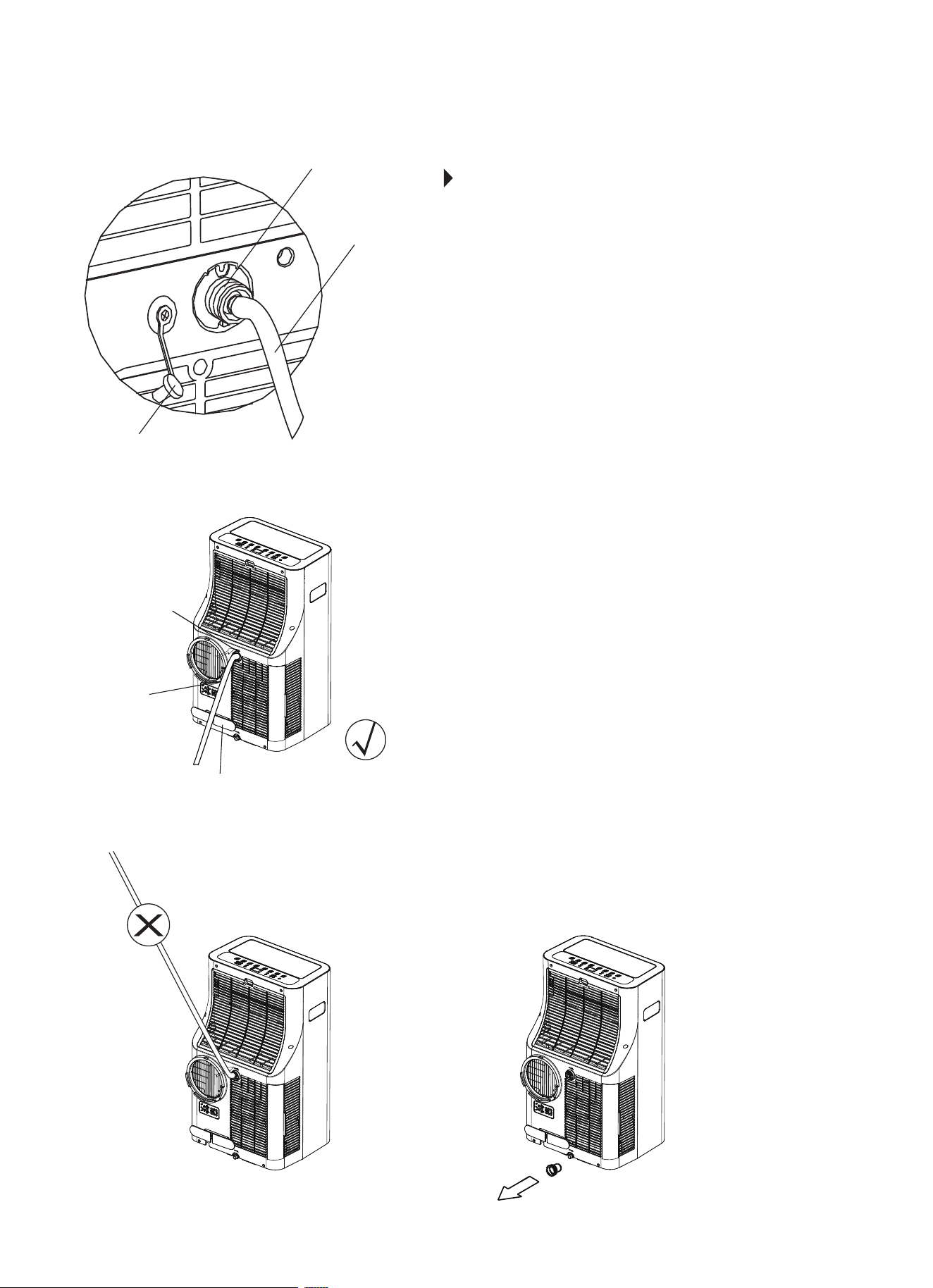
Remove the
upper drain plug
Continuous
drain hose
Press the power cord buckle
into the rear cover.
FIG. 23
FIG. 24
FIG. 25 FIG. 26
Remove the
upper drain plug
Continuous
drain hose
Threaded Adapter
(for garden hose
draining option)
WATER DRAINAGE
During dehumidifying mode, remove the upper drain plug from
the back of the unit and attach 3/4” vinyl tube included with
the unit (5/8” outer diameter). If a longer hose is needed, a vinyl
tube (3/4” inner diameter 5/8” outer diameter) can be purchased
at a local hardware store or a standard garden hose (not
included) may be attached to the threaded adapter and used for
continuous draining (for models with threaded adapters only). (A
hose length of no greater than 6 ft is recommended.) Place the
open end of the hose directly over the drain area in your oor.
See Fig. 23 & 24.
NOTE: Make sure the hose is secure so there are no leaks.
Direct the hose toward a oor drain, making sure that there
are no kinks that will stop the water ow. Place the end of the
hose into a drain and make sure the end of the hose is directed
downward to let the water ow smoothly. (See Fig. 23.) Never
allow the hose to be directed upward at any point. (Fig. 25.)
When the water level of the bottom tray reaches a
predetermined level, the unit beeps 8 times and the digital
display area shows “P1”. At this time the air conditioning/
dehumidication process will immediately stop. However, the
fan motor will continue to operate. (This is normal.) Carefully
move the unit to a drain location, remove the bottom drain plug
and drain the water (Fig. 26). You can carefully tilt the unit back
slightly to assist with drainage. Restart the machine until the
“P1” symbol disappears. If the P1 symbol will not clear after
following the above instructions and waiting a few minutes after
restarting the machine, call Consumer Services.
NOTE: Be sure to reinstall the bottom drain plug before using
the unit.
10
IMPORTANT
1. Be sure to unplug the unit before cleaning or servicing.
2. Do not use gasoline, thinner or other chemicals to clean the unit.
3. Do not wash the unit directly under a tap or using a hose. It may
cause electrical danger.
4. If the power cord is damaged, it should be repaired by an
authorized repairman.
CAUTION: DO NOT operate the unit without lter because dirt and
lint will clog the unit and reduce performance.
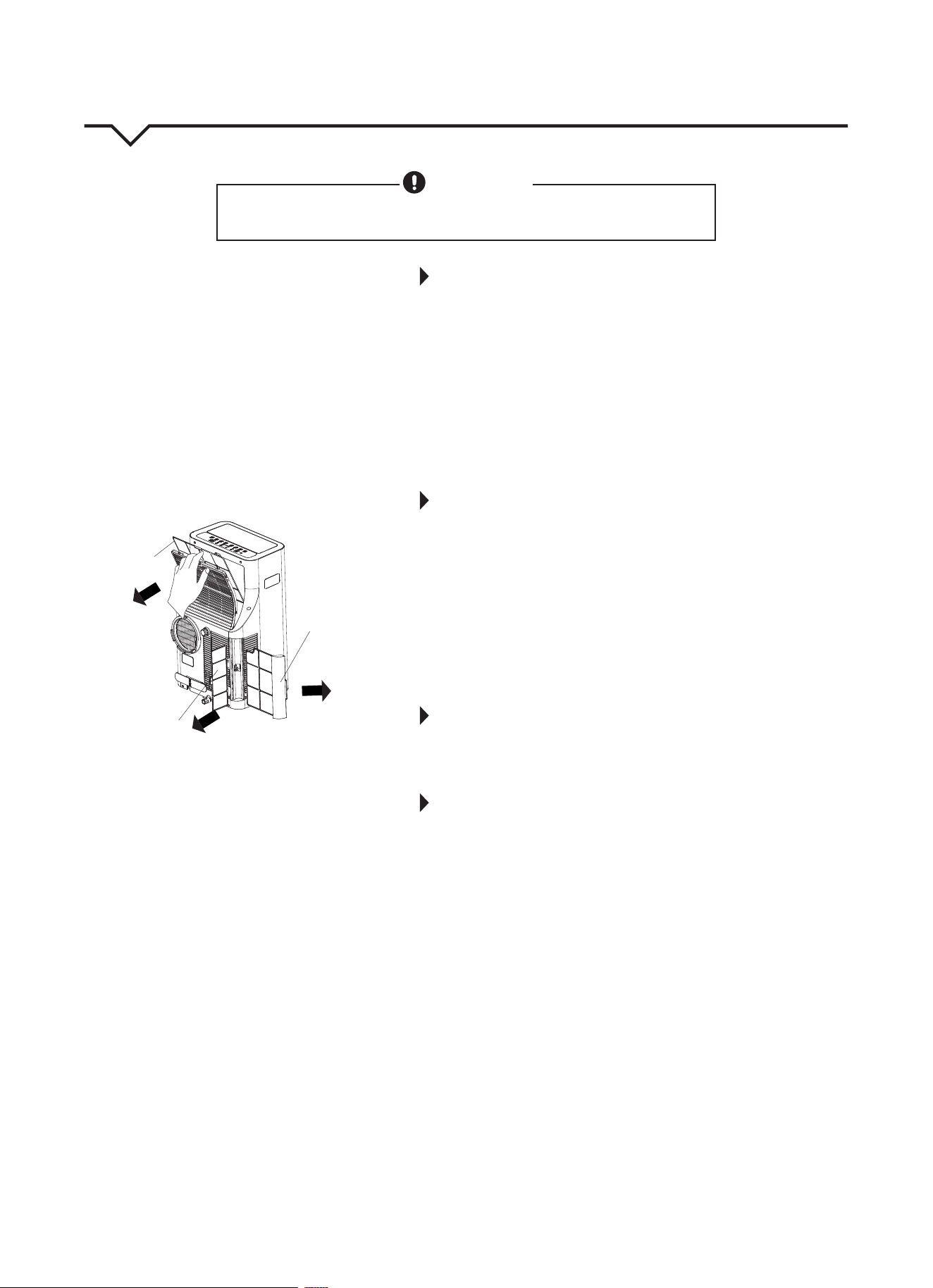
1. AIR FILTERS
Clean the air lters at least once every two weeks to prevent inferior
fan operation because of dust.
• REMOVAL: This unit has three lters. Take the lters out according
to Fig. 27.
• CLEANING: Wash the air lters by immersing them gently in warm
water (about 104°F/40°C) with a mild detergent. Rinse the lters
and dry them in a cool, dry place.
• MOUNTING: Reinstall all three lters before operating the unit.
2. UNIT ENCLOSURE
Use a lint-free cloth soaked with mild detergent to clean the unit
enclosure. Finish by using a dry, clean cloth.
3. UNIT IDLE FOR A LONG TIME
• Remove the rubber plug on the back of the unit and attach a
hose to drain outlet. Place the open end of the hose directly over
the drain area in your basement oor or over a shallow pan (if no
oor drain is available.) (See Fig. 23 & 24.) Remove the plug from
the bottom drain outlet; the water in the bottom tray will drain
out. (See Fig. 26.) Carefully tilt unit back slightly to assist with
water drainage from bottom drain outlet.
• Keep the appliance running on FAN mode for half a day (12
hours) in a warm room to dry the appliance inside and prevent
mold from forming.
• Stop the appliance and unplug it. Wrap the cord around the
power cord buckle and insert plug into power plug socket for
storage. Remove the batteries from the remote control.
• Clean all air lters and reinstall them.
• Disconnect the exhaust hose and keep it in a safe place.
Cover the window hole or remove slider kit from the
window completely.
• Remove the batteries from the remote control.
• Be sure to store the unit in a cool, dark place. Exposure to direct
sunshine or extreme heat can shorten the lifespan of the unit.
CARE AND MAINTENANCE
CAUTION
Clean air conditioner occasionally to keep it looking and operating like new.
Be sure to unplug the unit before cleaning to prevent shock or fire hazards.
Lower Filter A
(Press the grille
down slightly
and pull the
lower filter A
out at the
same time.)
Upper Filter
(take out)
Lower Filter B
(take out)
FIG. 27
11
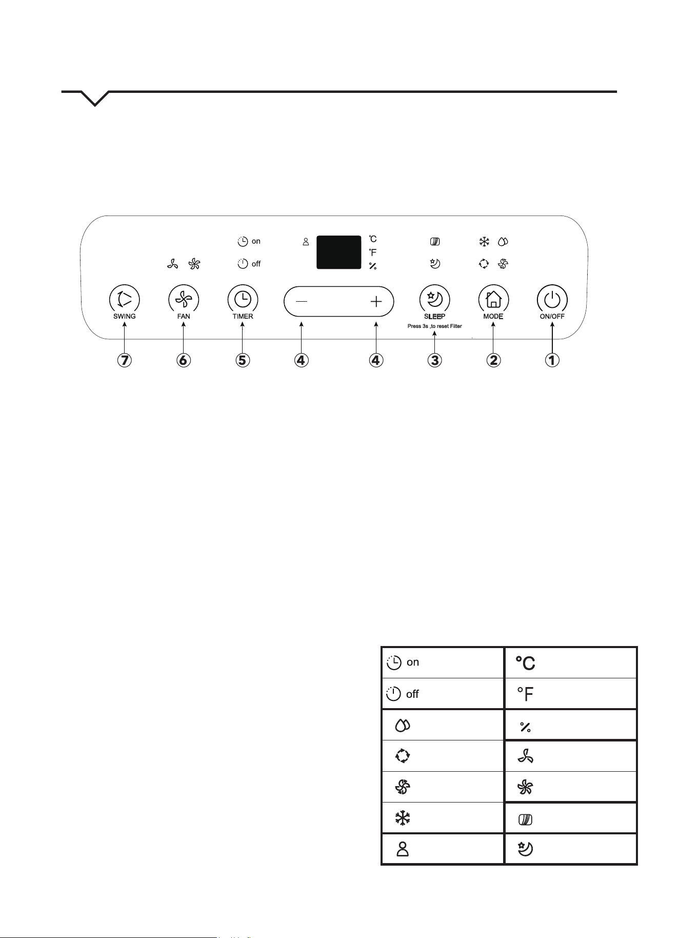
AIR CONDITIONER FEATURES
Thoroughly familiarize yourself with the control panel as shown below and all of its functions. Afterwards, follow the
symbol for the functions you desire. This unit can be controlled by the unit control or the remote control.
NOTE: This manual does not include Remote Control Operations; See the Remote Control Instructions packed with the
unit for details.
1. POWER button
Power switch ON/OFF.
2. MODE select button
Selects the appropriate operating mode. Each time you
press the button, a mode is selected in a sequence
that goes from AUTO, COOL, DRY, and FAN. The mode
indicator light illuminates next to the dierent mode
settings. NOTE: On DRY mode, you can adjust the
humidity for models with humidity sensor only.
3. SLEEP (ECO)/FILTER button
Used to initiate the SLEEP/ECO operation.
NOTE: After 250 hours of operation, the lter indicator
light illuminates. This feature is a reminder to clean the
Air Filter for more ecient operation. Press this button
for 3 seconds to cancel the reminder.
4. UP (+) and DOWN (—) buttons
Used to adjust (increase/decrease) temperature settings
(1°F/1°C increments) in a range of 62°F (17°C) to 86°F
(30°C) or to set the TIMER setting in a range of 0 – 24
hours or the humidity settings in a range of 35% RH
(Relative Humidity) to 85% RH
in 5% increments (only
for models with humidity sensor).
NOTE: The control is capable of displaying the
temperature in degrees Fahrenheit or degrees Celsius.
To convert from one to the other, press and hold the Up
and Down buttons at the same time for 3 seconds.
5. TIMER button
Used to initiate the AUTO ON start time and AUTO OFF
stop time program, in conjunction with the (+) and (—)
buttons. The timer ON/OFF indicator light illuminates
next to the timer ON/OFF settings.
6. FAN button
Control the fan speed. Press to select one of three fan
speeds: LOW, HI or AUTO. The fan speed indicator light
illuminates under dierent fan settings except AUTO
speed. When AUTO fan speed is selected all of the fan
indicator lights go dark.
NOTE: Press this button for 3 seconds to initiate ION
feature. The ion generator is energized and will help to
remove pollen and impurities from the air, trapping
them in the lter. Press it for 3 seconds again to stop
the ION feature.
7. SWING button
Used to initiate the Auto Swing feature. When the
operation is ON, press the SWING button to stop the
louver at a desired angle.
INDICATOR LIGHTS
Timer ON light Degrees Celsius
Timer OFF light Degrees Fahrenheit
Dry mode light
Humidity (on some
models only)
Auto mode light Low fan speed light
Fan mode light High fan speed light
Cool mode light Filter light
Follow Me light Sleep mode light
FIG. 28
12
OPERATING INSTRUCTIONS
COOL operation
• Press the “MODE” button until the “COOL”
indicator light comes on.
• Press the ADJUST buttons “+” or “—” to select
your desired room temperature. The temperature
can be set within a range of 62°F – 86°F
(17°C – 30°C).
• Press the “FAN” button to choose the fan speed.
DRY operation
• Press the “MODE” button until the “DRY” indicator
light comes on.
• Under this mode, you cannot select a fan speed or
adjust the temperature. The fan motor operates at
LOW speed.
• Keep windows and doors closed for a
dehumidifying eect.
• Do not put the duct to window when you cannot
set the humidity level (portable units without
humidity sensor).
• You can set the humidity level when the unit has a
humidity sensor. Please put the duct back into the
window for best dehumidication eect though
the duct does not need to connect to the window.
FAN operation
• Press the “MODE” button until the “FAN” indicator
light comes on.
• Press the “FAN” button to choose the fan speed.
The temperature cannot be adjusted.
• Remove exhaust hose and slider kit. (Do not put
the duct to window.)
AUTO operation
• When you set the air conditioner in AUTO mode,
it will automatically select cooling or fan only
operation depending on the temperature you have
selected and the room temperature.
• The air conditioner will maintain selected room
temperature.
• Under AUTO mode, you cannot select the
fan speed.
FOLLOW ME
This feature can ONLY be activated from the remote
control. The remote control serves as a remote
thermostat allowing for precise temperature control at
its location.
To activate the Follow Me feature, point the remote
control towards the unit and press the FOLLOW
ME button. The light on the unit control panel will
illuminate to indicate it received the signal. The
remote displays the actual temperature at its location.
The remote control will send this signal to the air
conditioner every 3 minutes until the FOLLOW ME
button is pressed again. If the unit does not receive
the Follow Me signal during any 7 minute interval,
the unit will beep to indicate use of the Follow Me
feature has ended. The display on the remote control
indicates the temperature at the remote ONLY.
TIMER operation
IF SETTING THE TIMER WHEN THE UNIT IS ON:
First press the TIMER button; the TIMER OFF
indicator light illuminates. It indicates the Auto Stop
program is initiated. Press the TIMER button again;
the TIMER ON indicator light illuminates. It indicates
the Auto Start program is initiated.
IF SETTING THE TIMER WHEN THE UNIT IS OFF:
First press the TIMER button; the TIMER ON
indicator light illuminates. It indicates the Auto Start
program is initiated. Press the TIMER button again;
the TIMER OFF indicator light illuminates. It indicates
the Auto Stop program is initiated.
• Press or hold the UP or DOWN button to change
the Auto time by 0.5 hour increments, up to 10
hours, then at 1 hour increments up to 24 hours.
The control will count down the time remaining
until start.
• The selected time will register in 5 seconds and
the system will automatically revert back to
displaying the previous temperature setting.
• The system will automatically revert back to
display the previous temperature setting if there is
no operation in a 5 second period.
• Turning the unit ON or OFF at any time or
adjusting the timer setting to 0.0 will cancel the
Auto Start/Stop timed program.
• If a malfunction occurs, the Auto Start/Stop timed
program will also be canceled.
SLEEP operation
In this mode the selected temperature will increase
(cooling) by 2°F/1°C or decrease by 2°F/1°C
(heating) 30 minutes after the mode is selected. The
temperature will then increase (cooling) or decrease
(heating) by another 2°F/1°C after an additional 30
minutes. This new temperature will be maintained
for 7 hours before it returns to the originally selected
temperature. This ends the SLEEP mode and the unit
will continue to operate as originally programmed.
NOTE: This sleep feature is not available under FAN or
DRY mode.
13
AUTO-RESTART
If the unit breaks o unexpectedly due to the power
being cut, it will restart with the previous function
setting automatically when the power is restored.
WAIT 3 MINUTES BEFORE RESUMING OPERATION.
After the unit has stopped, operation cannot be
restarted in the rst 3 minutes. This is to protect
the unit. Operation will automatically start after
3 minutes.
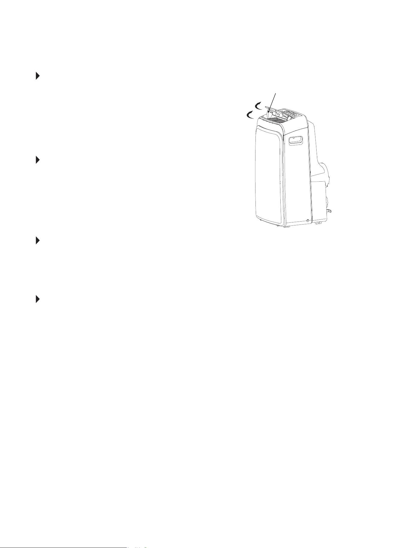
AIR FLOW DIRECTION ADJUSTMENT
The louver can be adjusted automatically.
Adjust the air ow direction automatically (Fig. 31):
• When the power is ON, the louver opens fully.
• Press the SWING button on the panel or remote
control to initiate the auto swing feature.
• The louver will swing up and down automatically.
PLEASE DO NOT ADJUST THE LOUVER AUTOMATICALLY.
LED DISPLAY
Shows the set temperature in °C or F, the Auto-timer
settings, ad the humidity settings (for models with
humidity sensor only). when on DRY and FAN modes,
it shows the room temperature. It also shows the
following Error and Protection Codes.
ERROR AND PROTECTION CODES
E1 - Room Temperature Sensor Error
E2 - Evaporator Temperature Sensor Error
E3 - Condenser Temperature Sensor Error
(on some models)
E4 - Display Panel Communication Error
E7 - Zero-crossing malfunction
NOTE: If any of the above errors occur, turn o the
unit and check for any obstructions. Restart
the unit. If the malfunction is still present,
unplug the unit and plug it back in. If error
repeats, call Consumer Services.
P1 - Bottom Tray is Full-
Remove bottom drain plug and empty the
collected water into a oor drain, outdoors,
or into a shallow pan. Carefully tilt unit back
slightly to assist the water in draining. If error
does not clear after emptying, call
Consumer Services.
PERFECT AIRE CONSUMER SERVICES TOLL FREE
NUMBER: 1.844.472.2473
Swings Automatically
FIG. 31

14
NOTE
A highly recommended troubleshoot for any issue in general consists of turning o unit and unplugging for 5
minutes. It is also recommended to try another wall outlet. For further assistance, contact Consumer Services
at 844-472-2473.
TROUBLESHOOTING
BEFORE CALLING FOR SERVICE, PLEASE REVIEW THE CHART BELOW
ISSUE POSSIBLE CAUSES
AIR CONDITIONER NOT
COOLING ROOM, OR NOT BLOWING
COLD AIR
• Be sure unit is not too large or too small for the area of the room.
• Verify that all doors, windows, curtains and any other openings are closed.
Verify nothing is obstructing the front grille of unit, such as curtains, etc.
• Allow enough time for room to cool, especially if outside temp is very high.
• Check that the lter is not dirty and louvers are open all the way and blowing in the
desired direction.
• Check that unit is set to COOL mode and that temperature is down enough (but
not too low).
• If unit is near a heat source, such as a stove, etc., relocate unit.
• If air coming from unit is cool to the touch, then unit is working properly; please
double check the rst three bullet points above.
• If using Follow Me remote feature, move remote away from unit.
• Unplug unit for at least 5 minutes. Follow Reset instructions on plug.
AIR CONDITIONER COOLING
BUT ROOM IS TOO WARM - ICE
FORMING ON COOLING COIL
BEHIND DECORATIVE FRONT
• Outdoor temperature is below 64ºF (18ºC). To defrost the coil, set to FAN
only mode.
• Air lter may be dirty. Clean lter. Refer to Care and Cleaning section. To defrost,
set to FAN only mode.
• Thermostat is set too cold for night-time cooling. To defrost the coil, set to FAN
only mode. Then, set temperature to a higher setting.
AIR CONDITIONER CYCLING ON
AND OFF TOO FREQUENTLY OR
NOT ENOUGH
• Be sure unit is not too large or too small for the area of the room.
• Make sure nothing is blocking the louvers.
• Make sure there is no dirt or debris inside the unit or on the lter.
UNIT WILL NOT TURN ON
• If P1 Error code appears, drain water from bottom tray
• Reset circuit breaker. Make sure there are not too many items (i.e. lamps, TV’s,
etc.) working o the same breaker.
• Check plug connection.
• If plug is operating on an on/o switch, be sure that the switch is ‘on’.
• Try plugging unit into another outlet.
• Check the temperature setting.
• Unplug unit for at least 5 minutes. Follow Reset instructions on plug.
UNIT BLOWS FUSES OR POPS
CIRCUIT BREAKER
• Make sure there are enough available amps on the circuit for the air conditioner.
• Large units which run on a 230v will require a dedicated 20 or 30 amp circuit.
AIR CONDITIONER IS
MAKING NOISES
• Check to be sure the unit is free from debris. Verify nothing is obstructing the unit.
• Check the fan blade for cracks or chips.
• Make sure the window slider kit is properly and securely mounted inside
the window.
• Clean the air lter.
REMOTE SENSING / FOLLOW ME
DEACTIVATING PREMATURELY
• Remote control not located within range. Place remote control within 20 ft and
180º radius of the front of the unit.
• Remote control signal obstructed. Remove obstruction.
• Replace batteries in remote control with a fresh set of batteries.


Distributed by:
Perfect Aire, LLC
5401 Dansher Rd.
Countryside, IL 60525
844-4PA-AIRE | 844-472-2473
www.perfectaire.us
PORTABLE
AIR CONDITIONER
FOR MODEL:
PORTQ12000
Before using your air conditioner, please
read this manual carefully and keep it for
future reference, along with your receipt.
Specification and performance data is subject to change without notice.
Printed in China
PA/User_PORTQ12000/03302018
USER MANUAL