Distributed by:
Perfect Aire, LLC
5401 Dansher Road
Countryside, iL 60525
844-4PA-AIRE | 844-472-2473
www.perfectaire.us
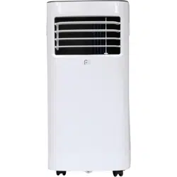
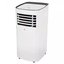
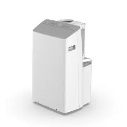
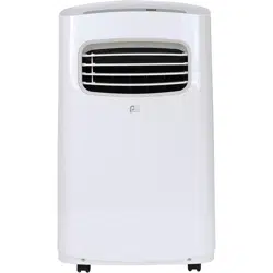
PORTABLE
AIR CONDITIONER
FOR MODELS:
PORT6000A
PORT8000A
PORT10000A
PORT12000A
Before using your air conditioner, please
read this manual carefully and keep it for
future reference, along with your receipt.
Specification and performance data is subject to change without notice.
Printed in China
PA/User_PORT-A/12212018
USER MANUAL

For your own records, please attach a copy of your sales receipt to this manual and complete the following:
Model Number:
_____________________________________ Serial Number: _______________________________________
Purchase Date: ____________________________________ Store Purchased: _____________________________________
Installation Date: ___________________________________ Installation Co.: _______________________________________
Installer Name:
_____________________________________ Installer Phone No.: ___________________________________
CONSUMER PRODUCT INFORMATION

SAFETY PRECAUTIONS ...................................................................1
IDENTIFICATION OF PARTS
...........................................................3
INSTALLATION INSTRUCTIONS
.....................................................5
CARE AND MAINTENANCE
............................................................10
AIR CONDITIONER FEATURES
.......................................................11
OPERATING INSTRUCTIONS
..........................................................12
TROUBLESHOOTING
.......................................................................14
CONTENTS
This manual provides the information needed for proper use and maintenance of
this air conditioner. Basic preventative care can help extend the life of this unit. The
“Troubleshooting” section in this manual contains a chart with solutions to the most
common problems. Referring to this section may save time and prevent the need for a
service call in the event of a problem.
NOTE: The Energy Rating for this unit is based on an installation using an unextended exhaust duct
without adapters A or B (as shown in the Installation Section of this manual).
ENERGY SAVING TIPS
• Usetheunitintherecommendedroomsize.
• Locatetheunitwherefurniturecannotobstructtheairow.
• Keepblinds/curtainsclosedduringthesunniestpartoftheday(coolingmode).
• Keeptheltersclean.
• Keepdoorsandwindowsclosedtokeepcoolairinandwarmairout(coolingmode)orkeepwarmairinandcoolair
out (heating mode for units with heat function).
NOTE:
Alltheillustrationsinthismanualareforexplanationpurposesonly.Unitpurchasedmaybeslightlydierent.
Thedesignandspecicationsaresubjecttochangewithoutpriornoticeforproductimprovement.ContactConsumer
Services at 844-4PA-AIRE (844-472-2473) for details.
OPERATING CONDITIONS
The air conditioner must be operated within the temperature range indicated below:
MODE ROOM TEMPERATURE
COOL
62°F (17°C) – 86°F (35°C)
DRY 55°F (13°C) – 86°F (35°C)
NOTE: Performance may be
reduced outside of these
operating temperatures.
1
WARNING
DO NOTstoreorusegasolineorotherammablevaporsandliquidsinthevicinityofthisoranyotherappliance.
DO NOTuseanextensioncordoranadapterplug;avoidrehazardorelectricshock.Donotremoveanyprong
from the power cord..
Besuretheelectricalserviceisadequateforthemodelyouhavechosen.Thisinformationcanbefoundonthe
serial plate, which is located on the side of the cabinet and behind the grille.
Besuretheairconditionerisproperlygrounded.Tominimizeshockorrehazards,propergroundingisimport-
ant.Thepowercordisequippedwithathree-pronggroundingplugforprotectionagainstshockhazards.
Your air conditioner must be used in a properly grounded wall receptacle. If the wall receptacle you intend to
useisnotadequatelygroundedorprotectedbyatimedelayfuseorcircuitbreaker,haveaqualiedelectrician
install the proper receptacle.
Ensure the receptacle is accessible after the unit installation.
READ SAFETY PRECAUTIONS BEFORE INSTALLATION
Topreventinjurytotheuserorotherpeopleandpropertydamage,thefollowinginstructionsmustbefollowed.
Incorrect operation due to ignoring of instructions may cause harm or damage.
NEVER DO THIS. ALWAYS DO THIS.
SAFETY PRECAUTIONS
CAUTION
• Contactaqualiedinstallerforinstallationofthisunitifnecessary.
• Contactaqualiedservicetechnicianforrepairormaintenanceofthisunit.
• Theairconditionerisnotintendedforusebyyoungchildrenwithoutsupervision.Youngchildrenshouldbesupervised
to ensure that they do not play with the air conditioner.
• Ifthepowercordistobereplaced,replacementworkshouldbeperformedbyauthorizedpersonnelonly.
• Installationandrepairworkmustbeperformedinaccordancewiththenationalwiringstandardsbyauthorized
personnel only.
• DO NOT operate your air conditioner in a wet room such as a bathroom or laundry room.
• Thisappliancecanbeusedbypersonswithreducedphysical,sensoryormentalcapabilitiesorlackofexperience
andknowledgeiftheyhavebeengivensupervisionorinstructionconcerninguseoftheapplianceinasafewayand
understandthehazardsinvolved.Cleaningandusermaintenanceshallnotbemadebychildrenwithoutsupervision.
• Childrenshouldbesupervisedtoensurethattheydonotplaywiththeappliance.
• Disabledpersonsmayrequireassistancewithsetupand/oruse.
• DO NOT operate the appliance with a damaged cord or plug. Call Consumer Services at 844-472-2473 if the power
supplycordand/orplugisdamaged;itmustbereplacedbyaqualiedservicetechnicianinordertoavoidahazard.
• Priortocleaningorothermaintenance,theappliancemustbedisconnectedfromitsmainpowersupply.
• DO NOT install the appliance in a location that may be exposed to combustible gas.
• Ifcombustiblegas(orotherammableliquidsorvapors)accumulatesaroundtheunit,itmaycausere.
• DO NOT run cord under carpeting. Do not cover cord with throw rugs, runners, or similar coverings. Do not route cord
underfurnitureorappliances.Arrangecordawayfromtracareaandwhereitwillnotbetrippedover.
• Toreducetheriskofreorelectricshock,donotusetheappliancewithanysolid-statespeedcontroldevice.
• Theapplianceshallbeinstalledinaccordancewithnationalwiringregulations.
• Whentherearedierencesbetween“USERMANUAL”and“RemoteControlManual”onfunctiondescription,the
descriptionon“USERMANUAL“shallprevail.

2
SAFETY PRECAUTIONS
Please read through these instructions before you start the installation process. Improper installation can cause damage
totheunit,yourpersonalproperty,andalsoposesapersonalsafetyhazard.
• Installationmustbeperformedaccordingtotheinstallationinstructions.Improperinstallationcancausewater
leakage,electricalshock,orre.
• Useonlytheincludedaccessoriesandparts,andspeciedtoolsfortheinstallation.Usingnon-standardpartscan
causewaterleakage,electricalshock,re,andinjuryorpropertydamage.
• Makesurethattheoutletyouareusingisgroundedandhastheappropriatevoltage.Thepowercordisequipped
withathree-pronggroundingplugtoprotectagainstshock.Voltageinformationcanbefoundonthesideoftheunit,
behindthegrille.Ifthewallreceptacleyouintendtouseisnotadequatelygroundedorprotectedbyatimedelayfuse
orcircuitbreaker,haveaqualiedelectricianinstalltheproperreceptacle.
• Ensurethereceptacleisaccessibleaftertheunitinstallation.
• Installtheunitonaat,level,sturdysurface.Failuretodosocouldresultindamageorexcessivenoiseandvibration.
• Theunitmustbekeptfreefromobstructiontoensureproperfunctionandtomitigatesafetyhazards.
• DO NOT modify the length of the power cord or use an extension cord to power the unit.
• DO NOT
shareasingleoutletwithotherelectricalappliances.Improperpowersupplycancausereorelectricalshock.
• DO NOT remove any prong from the power cord.
• DO NOT install your air conditioner in a wet room such as a bathroom or laundry room. Too much exposure to water
can cause electrical components to short circuit. Your air conditioner should be used in such a way that it is protected
from moisture (i.e. condensation, splashed water, etc.). Do not place your air conditioner where it can fall or be pulled
intowateroranyotherliquid.Iftheunitdoeseverfallintowater,unplugitimmediately.
• DO NOTinstalltheunitinalocationthatmaybeexposedtocombustiblegasorotherammableliquidsorvaporsas
thiscouldcausere.
• Theunithaswheelstofacilitatemoving.Makesurenottousethewheelsonthickcarpetortorolloverobjects,as
these could cause tipping. Always transport your air conditioner in a vertical position and stand on a stable, level
surface during use.
• DO NOT operate a unit that has been dropped or damaged.
• DO NOT
removeanyxedcoversfromtheunit.
• Onlyusetheincludedaccessoriesandspeciedpartsforinstallation.Usingnonstandardpartscancausewater
leakage,electricalshock,re,andinjuryorpropertydamage.
• Theunitmustbekeptfreefromobstructiontoensureproperfunction.Keepanairpathofatleast12in(30cm)all
around the unit from alls, furniture, and curtains.
• DO NOT allow children to play with the air conditioner. Children must be supervised around the unit at all times.
• Iftheairconditionerisknockedoverduringuse,turntheunitoandunplugitfromthemainpowersupply
immediately.Visuallyinspecttheunittoensurethereisnodamage.Ifyoususpecttheunithasbeendamaged,contact
a technician or customer service for assistance.
• Inathunderstorm,thepowermustbecutotoavoiddamagetothemachineduetolightning.
• Turnotheproductwhennotinuse.
• DO NOT touch the unit or plug with wet or damp hands or when barefoot.
• DO NOT
pressthebuttonsonthecontrolpanelwithanythingotherthanyourngers.
• DO NOTremoveanyxedcovers.Neverusethisapplianceifitisnotworkingproperlyorifithasbeendropped
or damaged.
• Neverusetheplugtostartorstoptheunit.(Alwaysusetheswitchonthecontrolpanelorremotetopowertheuniton
ando.)
• DO NOT use this product for functions other than those described in the instruction manual.
3
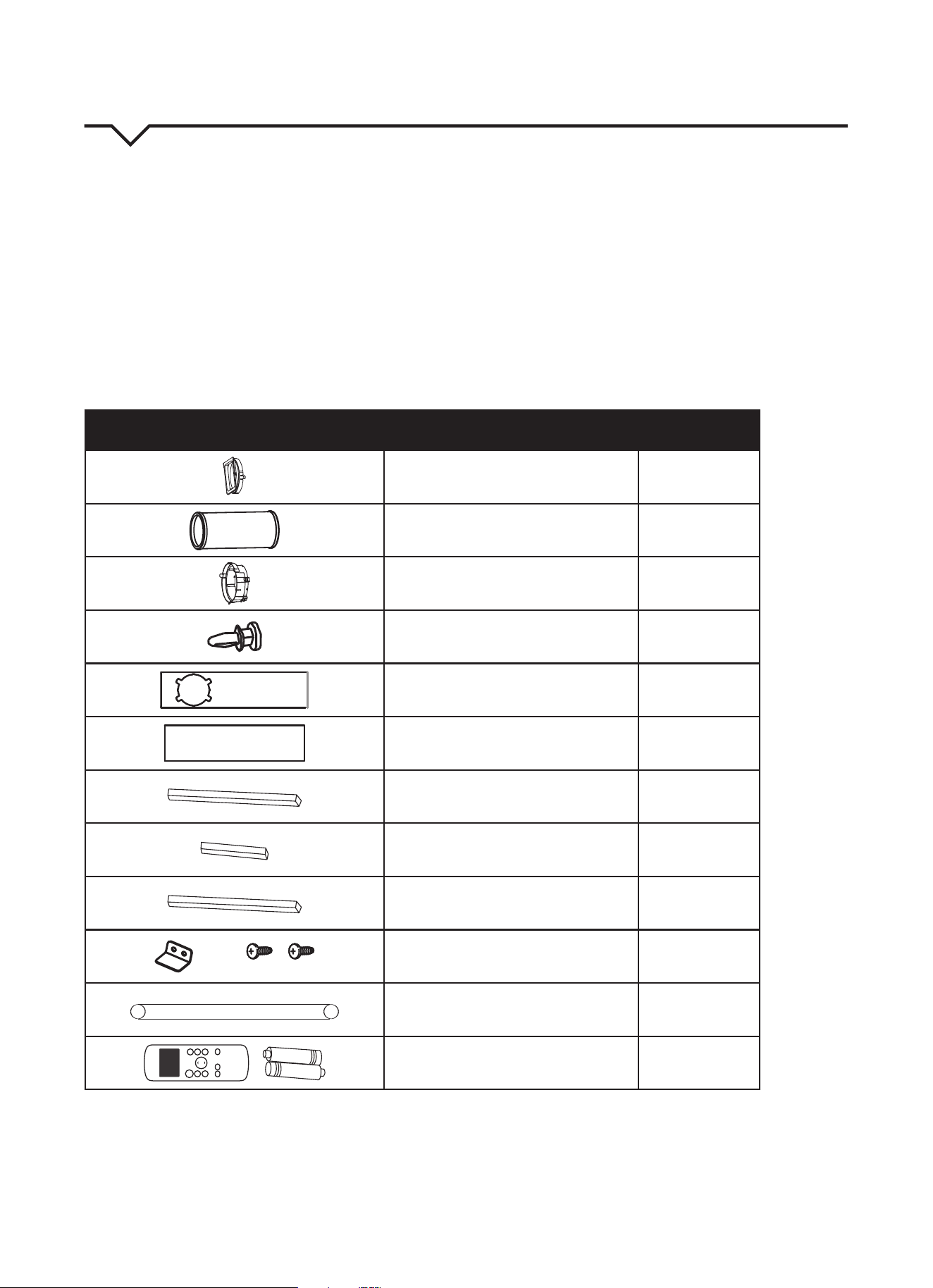
IDENTIFICATION OF PARTS
ACCESSORIES
Checkthatalltheaccessoriesareincludedinthepackage(Fig.1)andrefertotheinstallationinstructionsfortheirusage.
YourWindowInstallationKittswindows26.5–48inches(67.5–123cm)andcanbeshortenedforsmallerwindows.
Tools Needed:
• MediumPhillipsscrewdriver
• Tapemeasureorruler
• Knifeorscissors
• Saw(optional,toshortenwindowadapterfornarrowwindows)
PART DESCRIPTION QUANTITY
UnitAdapter 1 pc
Exhaust Hose 1 pc
WindowsliderAdapter 1 pc
Bolt 1 pc
WindowSliderA 1 pc
WindowSliderB 1 pc
Foam Seal A (Adhesive) 2 pcs
Foam Seal B (Adhesive) 2 pcs
Foam Seal C (Non-Adhesive) 1 pc
SecurityBracketand2Screws 1 set
Drain Hose 1 pc
ON/OF F
TEMP
S HO R T
C U T
TI ME R
O N
TI ME R
O F F
MO DE
FA N
S LE E P
S WI NG
LE D
Remote Control and Batteries 1 set
NOTE:
Alloftheillustrationsinthismanualareforexplanationpurposesonly.Yourairconditionermaybeslightlydierent.
FIG. 1
4
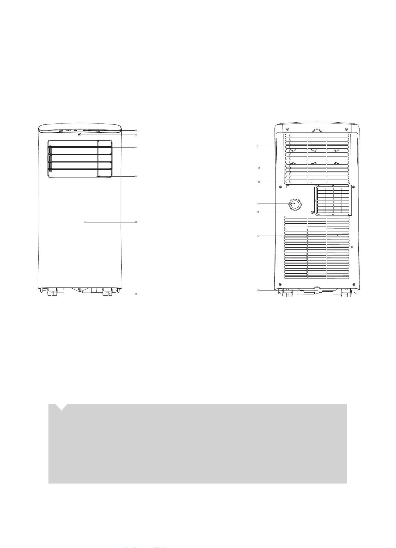
PARTS DIAGRAM
FRONT REAR
FIG. 2 FIG. 3
control panel
remote signal receptor (not visible)
horizontal louver control
lever (adjust manually)
vertical louver control
lever (adjust manually)
panel
caster
handle
(both sides)
bottom tray
drain outlet
grille/air filter
upper air intake
air outlet
lower air intake
drain outlet
ABOUT FLUORINATED GASES
• Thisairconditioningunitisahermeticallysealedunitthatcontainsfluorinatedgases.Forspecific
information on the type of gas and the amount, please refer to the relevant label on the unit itself.
• Installation,service,maintenanceandrepairofthisunitmustbeperformedbyacertifiedtechnician.
• Productuninstallationandrecyclingmustbeperformedbyacertifiedtechnician.
• Whentheunitischeckedforleaks,properrecord-keepingofallchecksisstronglyrecommended.
5
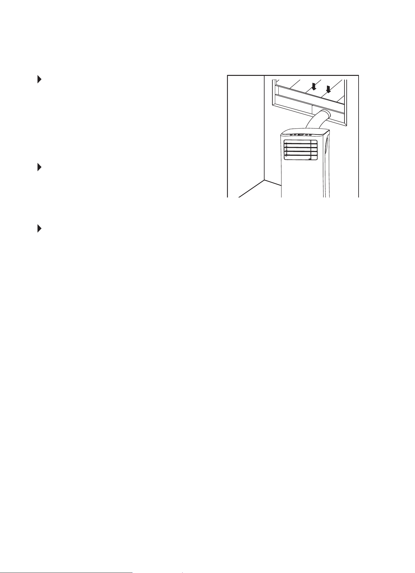
INSTALLATION INSTRUCTIONS
LOCATION
• Theairconditionershouldbeplacedonafirm
surfacetominimizenoiseandvibration.For
safe and secure positioning, place the unit on a
smooth, level floor strong enough to support it.
• Theunithascasterstoaidplacement;itshould
onlyberolledonsmooth,flatsurfaces.Use
caution when rolling on carpeted surfaces. Do not
attempttorolltheunitoverobjects.
• Theunitmustbeinstallednearagroundedplug;
theCollectionTrayDrain(foundonthebackofthe
unit) must be accessible.
• DONOTcovertheIntakes,OutletsorRemote
Signal Receptor of the unit, as this could prevent
the unit from running efficiently and can damage
the unit.
• Allowatleast12inches(30cm)ofspacefromthe
wall for efficient air-conditioning. (See Fig 4.)
WINDOW SLIDER KIT INSTALLATION
Yourwindowsliderkithasbeendesignedtot
moststandard“vertical”and“horizontal”window
applications. However, it may be necessary for you to
improvise or modify some aspects of the installation
procedures for certain types of windows. Please
refer to Fig. 5 and Fig. 6 for minimum and maximum
windowopenings.Windowsliderkitlengthcanbe
xedwithabolt.(SeeFig.7.)
NOTE: If the window opening is less than 2 ft., cut
the extension piece (See Fig. 7) shorter so the
kitproperlytsinthewindowopening.Onlycut
if absolutely necessary. Never cut the hole in the
windowsliderkit.
CAUTION
Makesuretherearenoobstaclesaroundtheair
outletoftheexhausthose(intherangeof20in./
500mm)inorderfortheexhaustsystemto
workproperly.
The exhaust hose and adapter must be installed
or removed in accordance with the usage mode as
indicated below:
COOLorAUTOmode Install Hose
FAN or DRY mode Remove Hose
12 in.
(30 cm)
12 in.
(30 cm)
FIG. 4
FIG. 6
FIG. 5
FIG. 7
Vertical
Window
Horizontal
Window
Extension
Piece
Window Slider Kit
Bolt
Window Slider Kit
Minimum: 2 ft. (67cm)
Maximum: 4 ft. (123 cm)
Window Slider Kit
Minimum: 2 ft. (67cm)
Maximum: 4 ft. (123 cm)
6
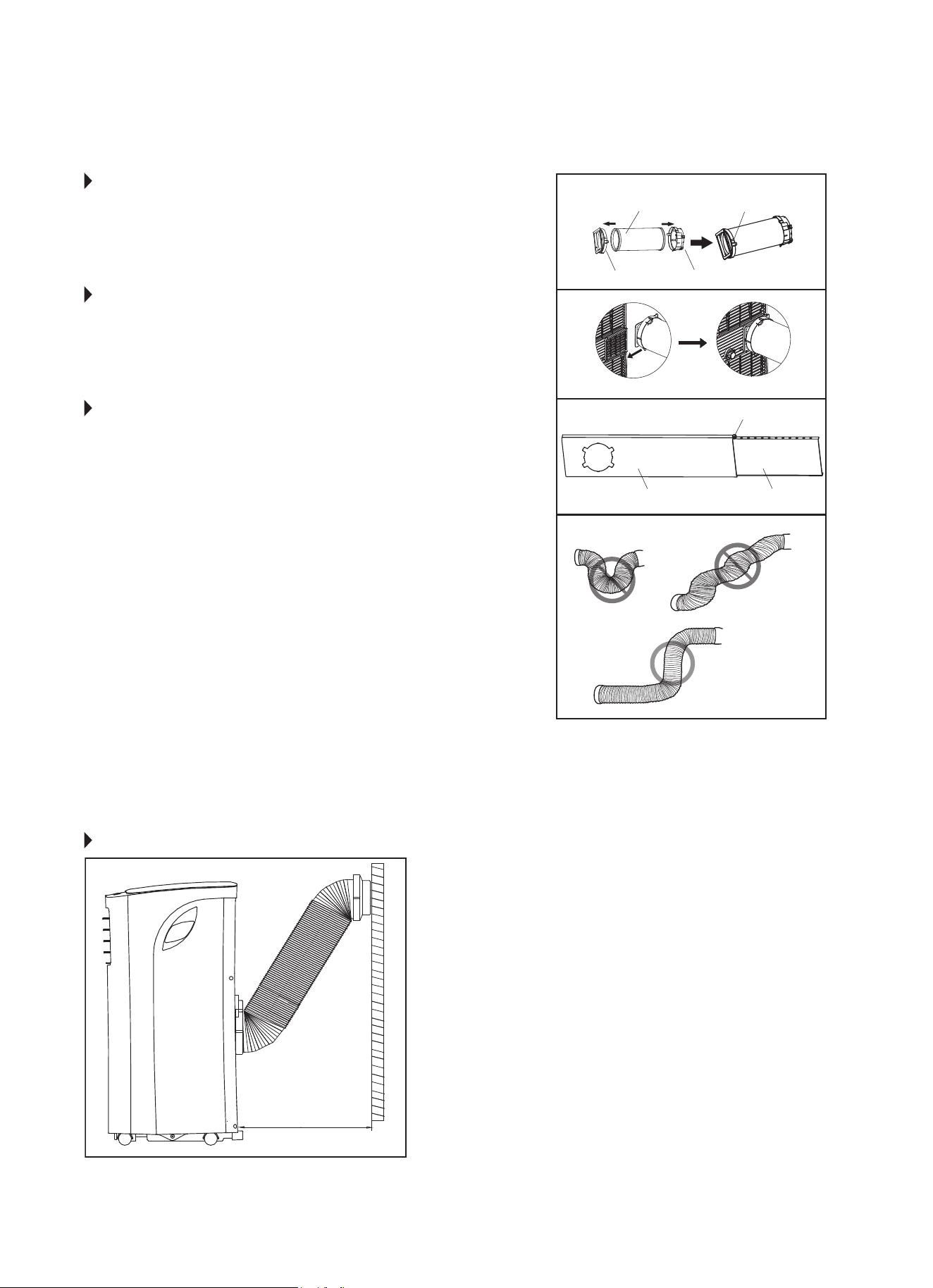
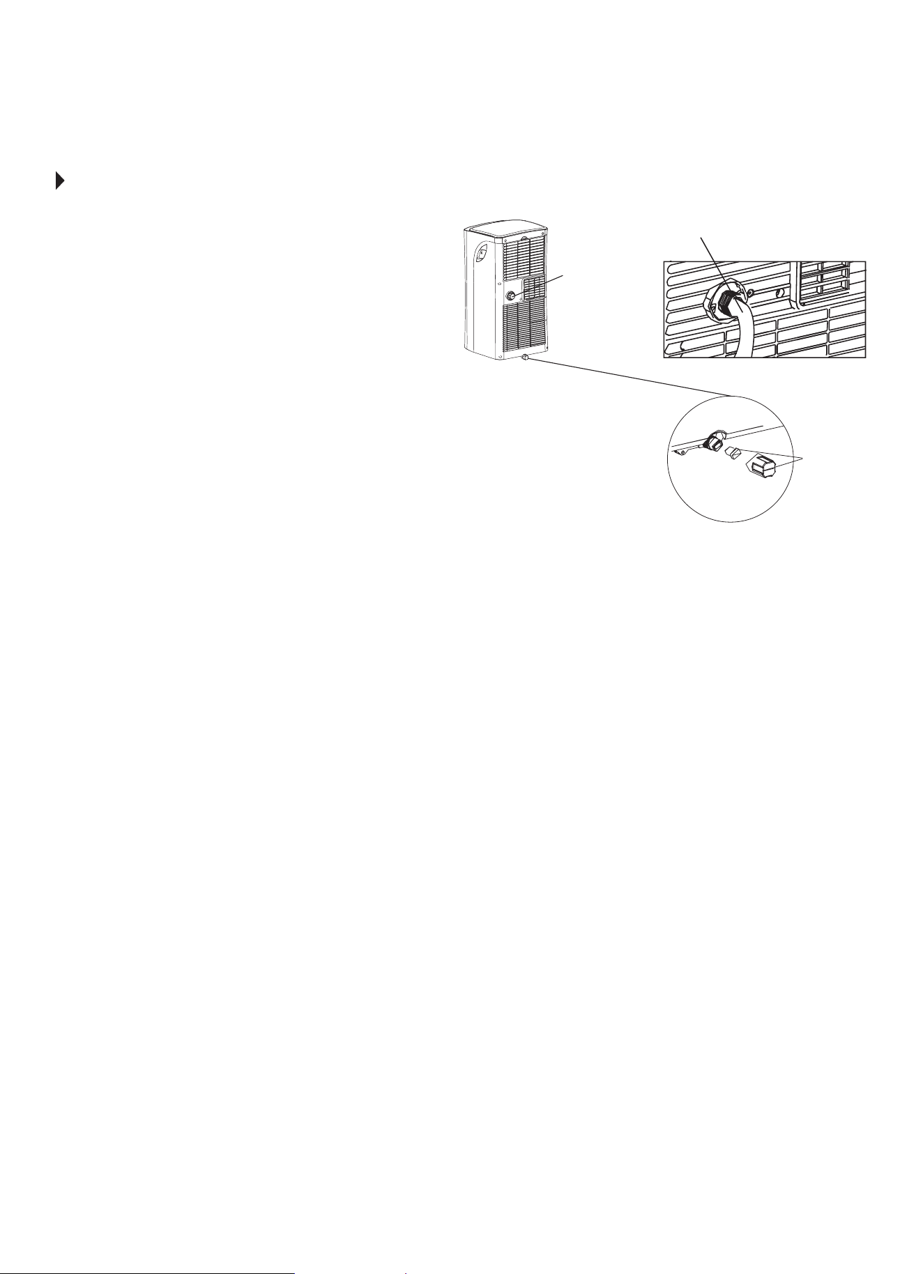
STEP 1:
PREPARING THE EXHAUST HOSE
ASSEMBLY
Fig. 8
Press the exhaust hose into the window slider adapter and
unit adapter; it will snap automatically to the adapters.
STEP 2:
INSTALL THE EXHAUST HOSE ASSEMBLY
TO THE UNIT
Fig. 9
Slide the Exhaust hose into the air outlet opening of the
unit along the arrow direction, from left to right.
STEP 3:
PREPARING THE ADJUSTABLE WINDOW
SLIDER
Fig. 10
a. Dependingonthesizeofyourwindow,adjustthesizeof
the window slider.
b.Ifthelengthofthewindowrequirestwowindowsliders,
use the bolt (included) to fasten the window sliders once
theyareadjustedtotheproperlength.
NOTE: To ensure proper function, DO NOT overextend or
bendthehose.Makesurethattherearenoobstacles
aroundtheairoutletoftheexhausthose(20inch
clearance)inordertoensuretheexhaustsystemworks
properly. (Fig. 11.)
Once the Exhaust Hose assembly is prepared, choose from
one of the following two installation methods:
• HungWindowInstallation(page7)
• SlidingWindowInstallation(page8)
Unit Adapter
Bolt (if needed)
Window Slider A Window Slider B
Window Slider Adapter
Exhaust Hose Exhaust Hose Assembly
FIG. 8
FIG. 9
FIG. 10
FIG. 11
RECOMMENDED INSTALLATION
19.7 inches
50 cm
NOTE: All the illustrations in this manual are
for explanation purposes only. Your unit
maybeslightlydierent.Theactualshape
of the unit prevails.
The unit can be controlled by it’s control
panel or with the remote control. This
manual does not include remote control
operations.SeetheRemoteControlUser
Manual included with the unit for details.
7
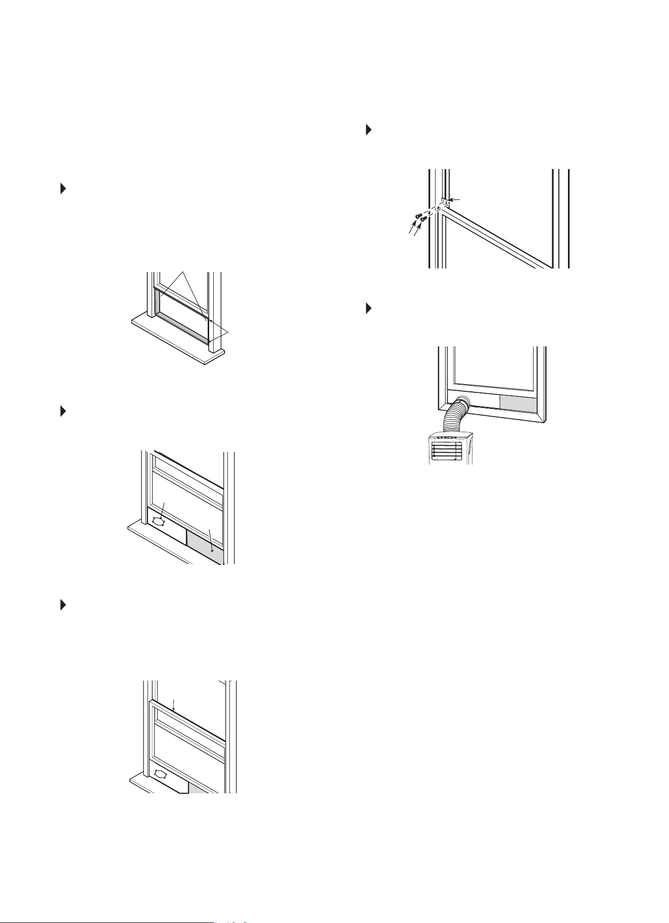
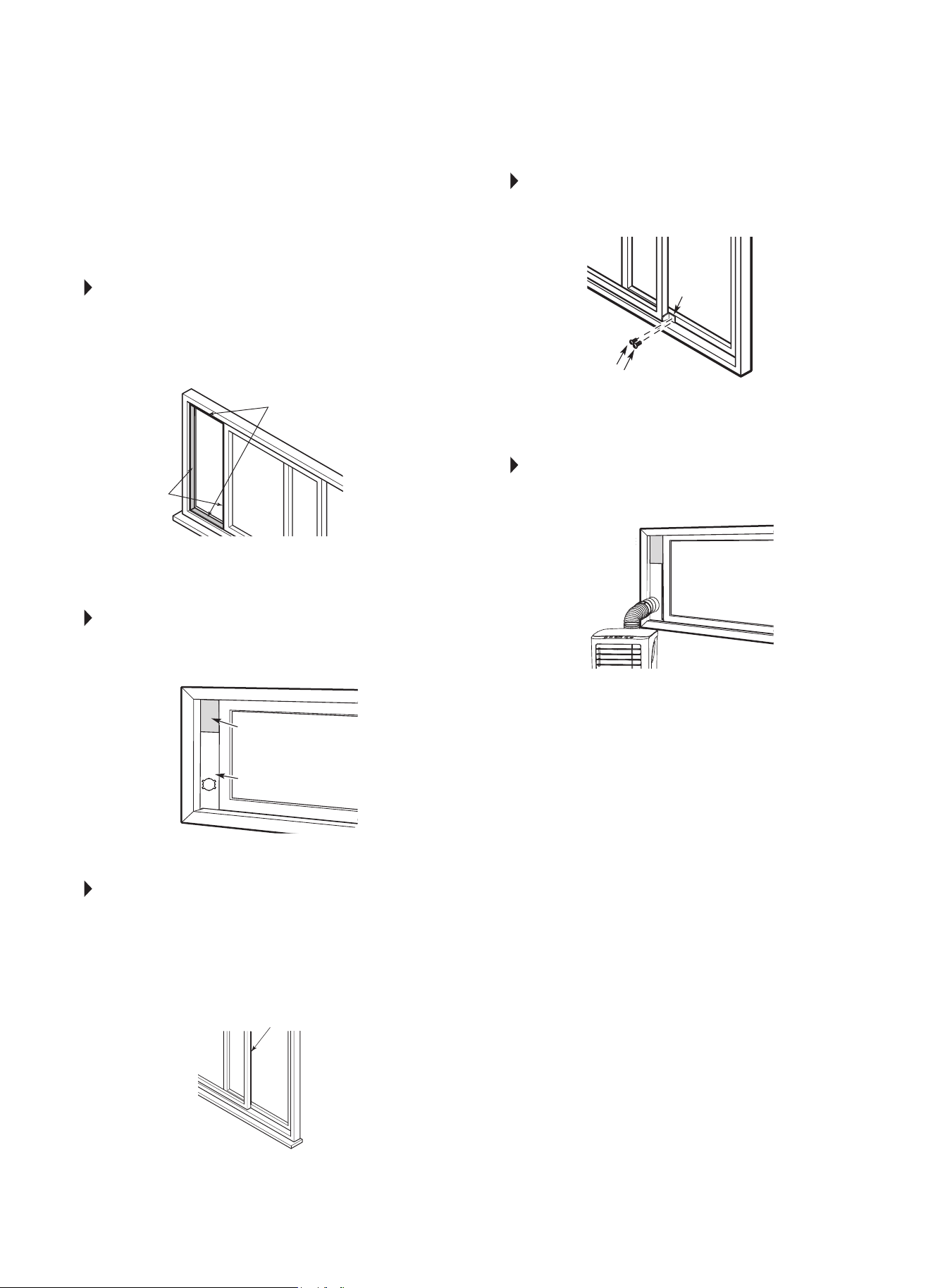
TYPE 1:
HUNG WINDOW INSTALLATION
STEP 1 Fig. 12
Cut the adhesive foam seal A and B strips to the
proper lengths, and attach them to the window sash
and frame as shown.
STEP 2 Fig. 13
Insert the window slider assembly into the window
opening.
STEP 3 Fig. 14
Cut the non-adhesive foam seal C strip to match
the width of the window. Insert the seal between
the glass and the window frame to prevent air and
insects from getting into the room.
STEP 4 Fig. 15
Ifdesired,installthesecuritybracketwith2screws
as shown.
STEP 5 Fig. 16
Insert the window slider adapter into the hole of the
window slider.
NOTE: All the illustrations in this manual are for
explanation purposes only. Your unit may be
slightlydierent.
Foam Seal B
(Adhesive type - shorter)
Foam Seal C
(Non-adhesive
type)
Window
Slider A
Window
Slider B
(if required)
Foam Seal A
(Adhesive type)
Security Bracket
FIG. 12
FIG. 13
FIG. 14
FIG. 15
FIG. 16
2 Screws
8
TYPE 2:
SLIDING WINDOW
INSTALLATION
STEP 1 Fig. 17
Cut the adhesive foam seal A and B strips to the
proper lengths, and attach them to the window sash
and frame as shown.
STEP 2 Fig. 18
Insert the window slider assembly into the window
opening.
STEP 3 Fig. 19
Cut the non-adhesive foam seal C strip to match
the width of the window. Insert the seal between
the glass and the window frame to prevent air and
insects from getting into the room.
STEP 4 Fig. 20
Ifdesired,installthesecuritybracketwith2screws
as shown.
STEP 5 Fig. 21
Insert the window slider adapter into the hole of the
window slider.
NOTE: All the illustrations in this manual are for
explanation purposes only. Your unit may be
slightlydierent.
FIG. 17
FIG. 18
FIG. 19
FIG. 20
FIG. 21
Foam Seal B
(Adhesive type - shorter)
Foam Seal A
(Adhesive type)
Foam Seal C
(Non-adhesive type)
Window
Slider A
Security
Bracket
2 Screws
Window
Slider B
(if required)
9
FIG. 22
Remove the
drain plug
Bottom
drain plug
Continuous
drain hose
WATER DRAINAGE
During dehumidifying mode, remove the drain plug
fromthebackoftheunit,installthedrainconnector
(5/8ʺuniversalfemalemender)with3/4ʺ hose (locally
purchased). For models without a drain connector,
justattachthedrainhosetothehole.Placetheopen
end of the hose directly over the drain area in your
basementoor.Besuretostoretheunitandinstallation
accessoriesinacool,darkplace.Exposuretodirect
sunshine or extreme heat can shorten the lifespan of
the unit.
Whenthewaterlevelofthebottomtrayreachesa
predetermined level, the unit beeps 8 times, and
the digital display shows “P1”. At this time the air
conditioning/dehumidicationprocesswillimmediately
stop. However, the fan motor will continue to operate
(this is normal). Carefully move the unit to a drain
location, remove the bottom drain plug and drain the
water. Reinstall the bottom drain plug and restart the
machine until the “P1” symbol disappears. If the error
repeats, call for service.
NOTE: Be sure to reinstall the bottom drain plug before
using the unit.
10
IMPORTANT SAFETY PRECAUTIONS
1. ALWAYSunplugtheunitbeforecleaningorservicing.
2. DONOTuseammableliquidsorchemicalstocleantheunit.
3. DO NOT wash the unit under running water. Doing so causes
electrical danger.
4. DO NOT operate the machine if the power supply cord has been
damaged during cleaning. A damaged power cord must be
replaced with a new cord from the manufacturer.
AIR FILTER MAINTENANCE
• Besuretocleantheairlterevery2weeksforoptimal
performance.
• Tocleanthelter,removeitasshowninFig.23.Then,carefully
vacuumthelterorwashitbyimmersingitgentlyinwarmwater
(about104°F)withamilddetergent.Rinsethelteranddryitin
acool,dryplace.Oncelterhasdriedcompletely,returnittothe
proper location on the unit.
• Thewatercollectiontrayshouldbedrainedimmediatelyaftera
P1 error occurs and before storage to prevent mold.
• Inhouseholdswithanimals,youwillhavetoperiodicallywipe
downthegrilleandcleantheairltertopreventblockedairow
due to animal hair.
CLEANING THE UNIT
Usealint-freeclothsoakedwithmilddetergenttocleantheunit
enclosure. Finish by using a dry, clean cloth.
STORING THE UNIT WHEN NOT IN USE
1. Drain the water collection tray according to the instructions in the
“WaterDrainage”section,page9.
2. Run the appliance on FAN mode for 12 hours in a warm room to
dry it and prevent mold.
3. Turnotheapplianceandunplugit.
4. Cleantheairlteraccordingtotheinstructionsinthe“AirFilter
Maintenance”section.Reinstalltheclean,drylterbeforestoring.
5. Remove the batteries from the remote control.
Besuretostoretheunitandinstallationaccessoriesinacool,dark
place. Exposure to direct sunshine or extreme heat can shorten the
lifespan of the unit.
CARE AND MAINTENANCE
CAUTION
Cleanairconditioneroccasionallytokeepitlookingandoperatinglikenew.
Be sure to unplug the unit before cleaning to prevent shock or fire hazards.
Grille/Air filter
FIG. 23
11
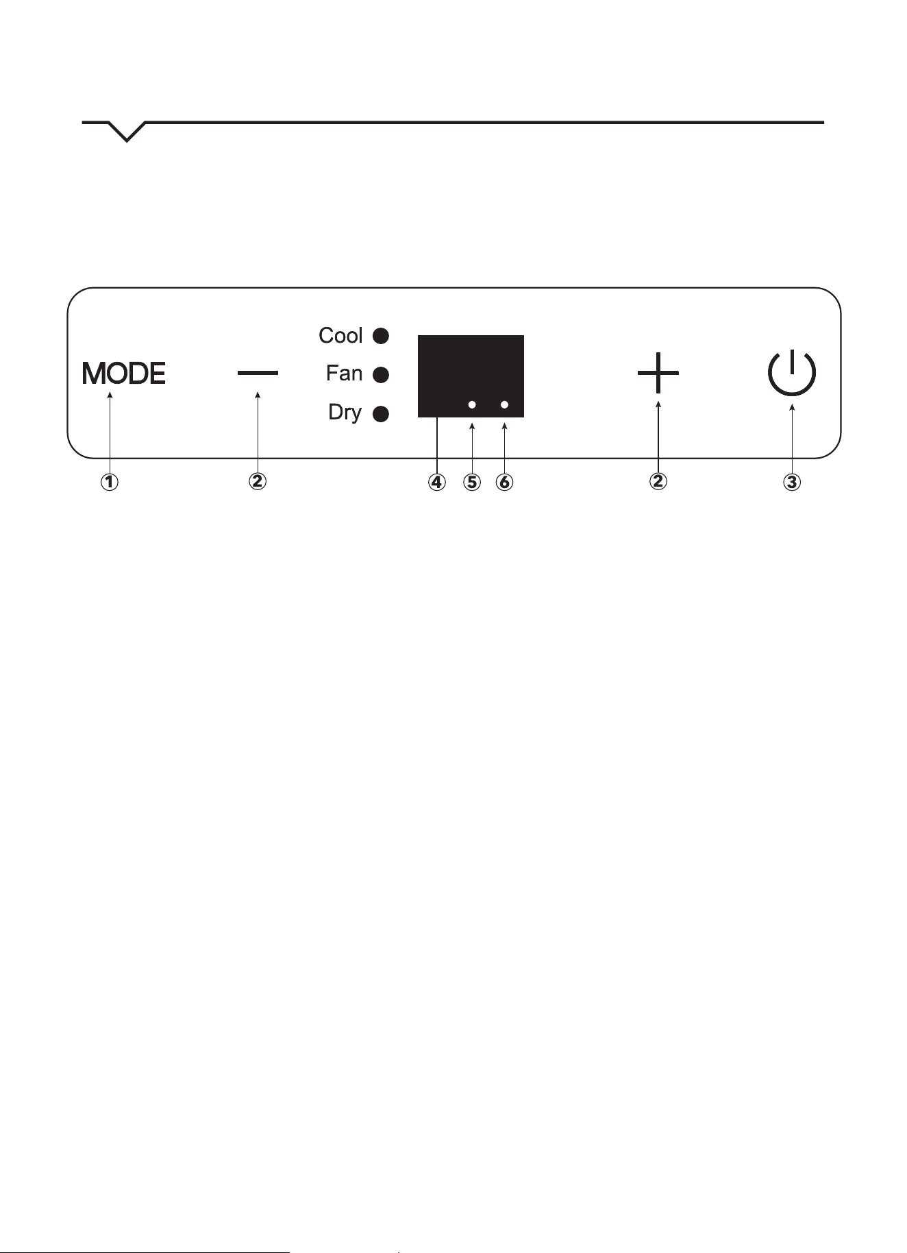
AIR CONDITIONER FEATURES
Thoroughlyfamiliarizeyourselfwiththecontrolpanelshownbelowandallofitsfunctions.Afterwards,followthesymbol
for the functions you desire. This unit can be controlled by the unit control or the remote control.
NOTE:
ThismanualdoesnotincludeRemoteControlOperations;seetheRemoteControlInstructionspackedwiththe
unit for details.
1. MODE button
Selects the appropriate operating mode. Each
time you press the button, a mode is selected in a
sequencethatgoesfromCOOL,FANandDRY.
Themodeindicatorlightilluminatesthedierent
mode setting.
NOTE: On above modes, the unit operates the auto
fan speed by default. You can set fan speed only by
usingtheremotecontrolonCOOLandFANmodes.
DRYmodewillonlyrunLOWfanspeed.
2. UP (+) and DOWN (—) buttons
Usedtoadjust(increase/decrease)temperature
settings(1°F/1°Cincrements)inarangeof62°F
(17°C)to86°F(30°C).
NOTE: The control is capable of displaying the
temperature in degrees Fahrenheit or degrees
Celsius. To convert from one to the other, press and
holdtheUpandDownbuttonsatthesametimefor
3 seconds.
3. POWER button
PowerswitchON/OFF.
4. LED display
ShowsthesettemperaturewhileonCOOLmode.
WhileonDRYandFANmodes,itshowstheroom
temperature.
DISPLAY ERROR CODES:
E1-Room temperature sensor error
E2-Evaporator temperature sensor error.
E4-Display panel communication error.
DISPLAY PROTECTION CODE:
P1-Bottom tray is full – Connect the drain hose and
drain the collected water away. If code repeats, call
Consumer Services at 844-472-2473.
NOTE:
Whenoneoftheabovemalfunctionsoccurs,
turnotheunitandcheckforanyobstructions.
Restart the unit; if the malfunction is still present,
turnotheunitandunplugthepowercord.
Call Consumer Services at 844-472-2473 for
further assistance.
5. Power indicator light
ONwhenunitiso.
6. Timer mode indicator light
Set only by remote control.
FIG. 24
12
OPERATING INSTRUCTIONS
NOTE: Fanspeeds,SLEEPmode,andFOLLOWME
featurecanonlybeadjustedwiththeremotecontrol.
NOTE:Whenselectingamodeontheunit’sdisplay,
fan speed cannot be selected. The fan speed goes to
“auto” by default.
COOL mode
• Pressthe“MODE”buttonuntilthe“COOL”
indicator light comes on.
• Pressthe“+”or“-”buttontoselectyourdesired
room temperature. The temperature can be set
withinarangeof62°F~86°F/17°C~30°C.
• Pressthe“FANSPEED”buttonontheremote
control to choose the fan speed.
FAN mode
• Pressthe“MODE”buttonuntilthe”FAN“indicator
light illuminates.
• Pressthe“FANSPEED”buttonontheremote
control to choose the fan speed. The temperature
cannotbeadjusted.
• Removeexhausthoseandslider.
DRY mode
• Pressthe“MODE”buttonuntilthe“DRY”indicator
light comes on.
• Underthismode,youcannotselectafanspeedor
adjustthetemperature.Thefanmotoroperatesat
LOWspeedonly.
• Keepwindowsanddoorsclosedforthebest
dehumidifyingeect.
• Removeexhausthoseandsliderwheninthis
mode.
SLEEP/ECO mode
NOTE: This feature can be activated from the remote
controlONLY.
ToactivateSLEEPfeature,thesettemperature
willincreaseby2°F(1°C)in30minutes.Theset
temperature will then increase by another 2°F(1°C)
afteranadditional30minutes.Thisnewtemperature
will be maintained for 7 hours before it returns to
the originally selected temperature. This ends the
SLEEPmodeandtheunitwillcontinuetooperateas
originally programmed.
NOTE: This feature is unavailable under FAN or
DRY mode.
FOLLOW ME feature
NOTE: This feature can be activated from the remote
controlONLY.
The remote control serves as a remote thermostat
allowing for the precise temperature control at its
location.ToactivatetheFOLLOWMEfeature,point
the remote control toward the unit and press the
FOLLOWMEbutton.Theremotedisplaystheactual
temperature at its location. The remote control will
send this signal to the air conditioner in 3 minute
intervalsuntiltheFOLLOWMEbuttonispressed
again.IftheunitdoesnotreceivetheFOLLOWME
signal during any 7 minute span, the unit will beep to
indicatetheFOLLOWMEmodehasended.
Auto-Restart
Iftheunitbreaksounexpectedlyduetothepower
being cut, it will automatically restart with the
previous function setting when the power resumes.
*WAIT 3 MINUTES BEFORE RESUMING OPERATION.
Operation will automatically start after 3 minutes (once
the unit is powered on). This is to protect the unit.
Air Flow Direction Adjustment
• Adjusttheairowdirectionmanuallybyusingthe
tab to move the louvers up or down.
• Donotplaceanyheavyobjectsorotherloadson
the louver; doing so will cause damage to the unit.
• Keepthelouverfullyopenedduringalloperations.
13
AUTO-RESTART
Iftheunitbreaksounexpectedlyduetothepower
being cut, it will restart with the previous function
setting automatically when the power is restored.
WAIT 3 MINUTES BEFORE RESUMING OPERATION.
After the unit has stopped, operation cannot be
restartedintherst3minutes.Thisistoprotectthe
unit. Operation will automatically start after
3 minutes.
AIR FLOW DIRECTION ADJUSTMENT
Thelouverscanbeadjustedmanually.(Fig.25.)Use
thetabtogentlyadjustlouversupanddownsoair
owispointedinthedesireddirection.Operatingthe
unit with the louvers closed (or only slightly open) will
not allow the unit to cool properly.
ERROR AND PROTECTION CODES
E1 - Room Temperature Sensor Error-
Unplugtheunitandplugitbackin.Iferror
repeats, call Consumer Services.
E2 - Evaporator Temperature Sensor Error-
Unplugtheunitandplugitbackin.Iferror
repeats, call Consumer Services.
E3 - Condenser Temperature Sensor Error-
Unplugtheunitandplugitbackin.Iferror
repeats, call Consumer Services.
E4 - Display Panel Communication Error-
Unplugtheunitandplugitbackin.Iferror
repeats, call Consumer Services.
EC - Refrigerant Leakage Detection Malfunction-
Unplugtheunitandplugitbackin.Iferror
repeats, call Consumer Services.
E7 - Zero-Crossing Malfunction-
Unplugtheunitandplugitbackin.Iferror
repeats, call Consumer Services.
P1 - Bottom Tray is Full-
Remove bottom drain plug and empty the
collectedwaterintoaoordrain,outdoors,
orintoashallowpan.Carefullytiltunitback
slightly to assist the water in draining. If error
does not clear after emptying, call
Consumer Services.
PERFECT AIRE CONSUMER SERVICES
TOLL FREE NUMBER: 1-844-472-2473
Tab
FIG. 25

14
NOTE
Ahighlyrecommendedtroubleshootforanyissueingeneralconsistsofturningounitandunpluggingfor5
minutes. It is also recommended to try another wall outlet. For further assistance, contact Consumer Services
at 844-472-2473.
TROUBLESHOOTING
BEFORE CALLING FOR SERVICE, PLEASE REVIEW THE CHART BELOW
ISSUE POSSIBLE CAUSES
AIR CONDITIONER NOT
COOLING ROOM, OR NOT BLOWING
COLD AIR
•Besureunitisnottoolargeortoosmallfortheareaoftheroom.
•Verifythatalldoors,windows,curtainsandanyotheropeningsareclosed.
Verifynothingisobstructingthefrontgrilleofunit,suchascurtains,etc.
•Allowenoughtimeforroomtocool,especiallyifoutsidetempisveryhigh.
•Checkthatthelterisnotdirtyandlouversareopenallthewayandblowinginthe
desired direction.
•CheckthatunitissettoCOOLmodeandthattemperatureisdownenough(but
not too low).
•Ifunitisnearaheatsource,suchasastove,etc.,relocateunit.
•Ifaircomingfromunitiscooltothetouch,thenunitisworkingproperly;please
doublechecktherstthreebulletpointsabove.
•TryusingtheFollowMefeatureformoreevencooling.
•IfusingFollowMeremotefeature,moveremoteawayfromunit.(Ensure,however,
thattheremotecontroliswithin20ftanda180°radiusofthefrontoftheunit.)
•Unplugunitforatleast5minutes.FollowResetinstructionsonplug.
AIR CONDITIONER COOLING
BUT ROOM IS TOO WARM - ICE
FORMING ON COOLING COIL
BEHIND DECORATIVE FRONT
•Outdoortemperatureisbelow64ºF(18ºC).Todefrostthecoil,settoFAN
only mode.
•Airltermaybedirty.Cleanlter.RefertoCareandCleaningsection.Todefrost,
set to FAN only mode.
•Thermostatissettoocoldfornight-timecooling.Todefrostthecoil,settoFAN
only mode. Then, set temperature to a higher setting.
AIR CONDITIONER CYCLING ON
AND OFF TOO FREQUENTLY OR
NOT ENOUGH
•Besureunitisnottoolargeortoosmallfortheareaoftheroom.
•Makesurenothingisblockingthelouvers.
•Makesurethereisnodirtordebrisinsidetheunitoronthelter.
•TryusingtheFollowMefeatureformoreevencooling.
UNIT WILL NOT TURN ON
•Resetcircuitbreaker.Makesuretherearenottoomanyitems(i.e.lamps,TV’s,
etc.)workingothesamebreaker.
•Checkplugconnection.
•Ifplugisoperatingonanon/oswitch,besurethattheswitchis‘on’.
•Trypluggingunitintoanotheroutlet.
•Unplugunitforatleast5minutes.FollowResetinstructionsonplug.
UNIT BLOWS FUSES OR POPS
CIRCUIT BREAKER
•Makesurethereareenoughavailableampsonthecircuitfortheairconditioner.
•Largeunitswhichrunona230vwillrequireadedicated20or30ampcircuit.
AIR CONDITIONER IS
MAKING NOISES
•Checktobesuretheunitisfreefromdebris.Verifynothingisobstructingtheunit.
•Checkthefanbladeforcracksorchips.
•Makesurethewindowsliderkitisproperlyandsecurelymountedinside
the window.
•Cleantheairlter.
•Makesureunitisonaat,levelsurface.
REMOTE SENSING / FOLLOW ME
DEACTIVATING PREMATURELY
•Remotecontrolnotlocatedwithinrange.Placeremotecontrolwithin20ftand
180ºradiusofthefrontoftheunit.
•Remotecontrolsignalobstructed.Removeobstruction.
•Replacebatteriesinremotecontrolwithafreshsetofbatteries.


Distributed by:
Perfect Aire, LLC
5401 Dansher Road
Countryside, iL 60525
844-4PA-AIRE | 844-472-2473
www.perfectaire.us
PORTABLE
AIR CONDITIONER
FOR MODELS:
PORT6000A
PORT8000A
PORT10000A
PORT12000A
Before using your air conditioner, please
read this manual carefully and keep it for
future reference, along with your receipt.
Specification and performance data is subject to change without notice.
Printed in China
PA/User_PORT-A/12212018
USER MANUAL