PORTABLE AIR CONDITIONER
WITH HEAT PUMP
MODELS: 1PORTVP12000
OWNER’S MANUAL


CONTENTS
(Continued)
SAFETY PRECAUTIONS
Safety precautions ...................................................................................................................................................................1
INSTALLATION INSTRUCTIONS
Preparation ...............................................................................................................................................................................8
Ambient temperature range for unit operating .......................................................................................................................8
Choosing the right location .....................................................................................................................................................8
Tools needed .............................................................................................................................................................................8
Accessories ...............................................................................................................................................................................8
Preparing the window slider kit............................................................................................................................................. 10
Preparing the air hose ........................................................................................................................................................... 10
Air hose insulator Installation (only for heat pump model) .................................................................................................. 11
Installation ............................................................................................................................................................................. 11
OPERATING INSTRUCTIONS
Control panel ......................................................................................................................................................................... 13
Operation instructions .......................................................................................................................................................... 14
Additional features ................................................................................................................................................................ 15
MAINTENANCE
Safety precautions ................................................................................................................................................................ 17
Air lter cleaning ................................................................................................................................................................... 17
Unit cleaning ......................................................................................................................................................................... 17
Storage when not in use ........................................................................................................................................................ 17
TROUBLESHOOTING TIPS
Troubleshooting tips ............................................................................................................................................................. 18
SAFETY & PRECAUTIONS
CONTINUEDCONTINUED
SAFETY PRECAUTIONS
(Continued)
1
DO NOT store or use gasoline or other ammable vapors and liquids in the vicinity of this or any other appliance.
DO NOT use an extension cord or an adapter plug; avoid re hazard or electric shock. Do not remove any prong from the power cord..
Be sure the electrical service is adequate for the model you have chosen. This information can be found on the serial plate, which is located on the side of
the cabinet and behind the grille.
Be sure the air conditioner is properly grounded. To minimize shock or re hazards, proper grounding is important. The power cord is equipped with a
three-prong grounding plug for protection against shock hazards.
Your air conditioner must be used in a properly grounded wall receptacle. If the wall receptacle you intend to use is not adequately grounded or
protected by a time delay fuse or circuit breaker, have a qualied electrician install the proper receptacle.
Ensure the receptacle is accessible after the unit installation.
READ SAFETY PRECAUTIONS BEFORE INSTALLATION
To prevent injury to the user or other people and property damage, the following instructions must be followed. Incorrect operation
due to ignoring of instructions may cause harm or damage.
NEVER DO THIS. ALWAYS DO THIS.
• Contact a qualied installer for installation of this unit if necessary.
• Contact a qualied service technician for repair or maintenance of this unit.
• The air conditioner is not intended for use by young children without supervision. Young children should be supervised to ensure that they do not
play with the air conditioner.
• If the power cord is to be replaced, replacement work should be performed by authorized personnel only.
• Installation and repair work must be performed in accordance with the national wiring standards by authorized personnel only.
• DO NOT operate your air conditioner in a wet room such as a bathroom or laundry room.
• This appliance can be used by persons with reduced physical, sensory or mental capabilities or lack of experience and knowledge if they have been
given supervision or instruction concerning use of the appliance in a safe way and understand the hazards involved. Cleaning and user maintenance
shall not be made by children without supervision.
• Children should be supervised to ensure that they do not play with the appliance.
• Disabled persons may require assistance with setup and/or use.
• DO NOT operate the appliance with a damaged cord or plug. Call Consumer Services at 844-472-2473 if the power supply cord and/or plug is
damaged; it must be replaced by a qualied service technician in order to avoid a hazard.
• Prior to cleaning or other maintenance, the appliance must be disconnected from its main power supply.
• DO NOT install the appliance in a location that may be exposed to combustible gas.
• If combustible gas (or other ammable liquids or vapors) accumulates around the unit, it may cause re.
• DO NOT run cord under carpeting. Do not cover cord with throw rugs, runners, or similar coverings. Do not route cord under furniture or appliances.
Arrange cord away from trac area and where it will not be tripped over.
• To reduce the risk of re or electric shock, do not use the appliance with any solid-state speed control device.
• The appliance shall be installed in accordance with national wiring regulations.
• When there are dierences in function descriptions between the “USER MANUAL” and the “REMOTE CONTROL MANUAL”, follow the “USER MANUAL.
WARNING
CAUTION

SAFETY PRECAUTIONS
(Continued)
• Installation must be performed according to the installation instructions. Improper installation can cause water leakage, electrical shock, or re.
• Use only the included accessories and parts, and specied tools for the installation. Using non-standard parts can cause water leakage, electrical
shock, re, and injury or property damage.
• Make sure that the outlet you are using is grounded and has the appropriate voltage. The power cord is equipped with a three-prong grounding plug
to protect against shock. Voltage information can be found on the side of the unit, behind the grille. If the wall receptacle you intend to use is not
adequately grounded or protected by a time delay fuse or circuit breaker, have a qualied electrician install the proper receptacle.
• Ensure the receptacle is accessible after the unit installation.
• Install the unit on a at, level, sturdy surface. Failure to do so could result in damage or excessive noise and vibration.
• The unit must be kept free from obstruction to ensure proper function and to mitigate safety hazards.
• DO NOT modify the length of the power cord or use an extension cord to power the unit.
• DO NOT share a single outlet with other electrical appliances. Improper power supply can cause re or electrical shock.
• DO NOT remove any prong from the power cord.
• DO NOT install your air conditioner in a wet room such as a bathroom or laundry room. Too much exposure to water can cause electrical components
to short circuit. Your air conditioner should be used in such a way that it is protected from moisture (i.e. condensation, splashed water, etc.). Do not
place your air conditioner where it can fall or be pulled into water or any other liquid. If the unit does ever fall into water, unplug it immediately.
• DO NOT install the unit in a location that may be exposed to combustible gas or other ammable liquids or vapors as this could cause re.
• The unit has wheels to facilitate moving. Make sure not to use the wheels on thick carpet or to roll over objects, as these could cause tipping. Always
transport your air conditioner in a vertical position and stand on a stable, level surface during use.
• DO NOT operate a unit that has been dropped or damaged.
• DO NOT remove any xed covers from the unit.
• Only use the included accessories and specied parts for installation. Using nonstandard parts can cause water leakage, electrical shock, re, and
injury or property damage.
• The unit must be kept free from obstruction to ensure proper function. Keep an air path of at least 12 in (30 cm) all around the unit from alls, furniture,
and curtains.
• DO NOT allow children to play with the air conditioner. Children must be supervised around the unit at all times.
• If the air conditioner is knocked over during use, turn the unit o and unplug it from the main power supply immediately. Visually inspect the unit to
ensure there is no damage. If you suspect the unit has been damaged, contact a technician or customer service for assistance.
• In a thunderstorm, the power must be cut o to avoid damage to the machine due to lightning.
• Turn o the product when not in use.
• DO NOT touch the unit or plug with wet or damp hands or when barefoot.
• DO NOT press the buttons on the control panel with anything other than your ngers.
• DO NOT remove any xed covers. Never use this appliance if it is not working properly or if it has been dropped
or damaged.
• Never use the plug to start or stop the unit. (Always use the switch on the control panel or remote to power the unit on and o.)
• DO NOT use this product for functions other than those described in the instruction manual.
IMPORTANT NOTE: Please read through these instructions before you start the installation process. Improper installation
can cause damage to the unit, your personal property, and also poses a personal safety hazard.
2
SAFETY & PRECAUTIONS
CONTINUEDCONTINUED
SAFETY PRECAUTIONS
(Continued)
• Do not use means to accelerate the defrosting process or to clean, other than those recommended by the manufacturer.
• The appliance shall be stored in a room without continuously operating ignition sources (for example: open ames, an operating gas appliance) and ignition
sources or (for example: an operating electric heater) close to the appliance. The appliance shall be stored in a room without continuously operating ignition
sources (for example: open ames, an operating gas appliance or an operating electric heater).
• Do not pierce or burn.
• Be aware that the refrigerants may not contain an odor.
• Compliance with national gas regulations shall be observed.
• Keep ventilation openings clear of obstruction.
• The appliance shall be stored so as to prevent mechanical damage from occurring.
• A warning that the appliance shall be stored in a well-ventilated area where the room size corresponds to the room area as specied for operation.
• Any person who is involved with working on or breaking into a refrigerant circuit should hold a current valid certicate from an industry-accredited
assessment authority, which authorizes their competence to handle refrigerants safely in accordance with an industry recognized assessment specication.
• Servicing should only be performed as recommended by the equipment manufacturer. Maintenance and repair requiring the assistance of other skilled
personnel shall be carried out under the supervision of the person competent in the use of ammable refrigerants.
• DO NOT modify the length of the power cord or use an extension cord to power the unit.
• DO NOT share a single outlet with other electrical appliances. Improper power supply can cause re or electrical shock.
• Please follow the instructions carefully to handle, install, clear, service the air conditioner to avoid any damage or hazard. Flammable Refrigerant R32 is used
within the air conditioner. When maintaining or disposing the air conditioner, the refrigerant (R32 or R290) should be recovered properly and should not be
discharged into the air directly.
• DO NOT have any open re or device-like switch which may generate a spark/arcing around the air conditioner to avoid causing ignition of the ammable
refrigerant used.
• Please follow the instructions carefully to store or maintain the air conditioner to prevent mechanical damage from occurring.
• Flammable refrigerant - R32 is used in air conditioner. Please follow the instructions carefully to avoid any hazard.
IMPORTANT NOTE: Read this manual carefully before installing or operating your new air conditioning
unit. Make sure to save this manual for future reference.
CAUTION
Risk of re/ammable materials
(Required for R32/R290 units only
WARNING (For using R290/R32 refrigerant only)
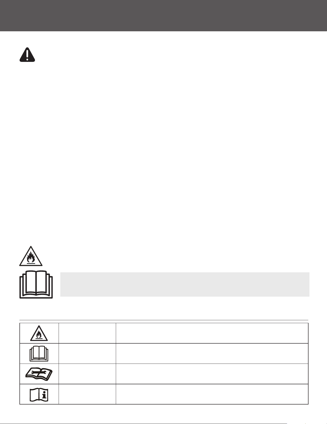
EXPLANATION OF SYMBOLS DISPLAYED ON THE UNIT
WARNING
This symbol shows that this appliance used a ammable refrigerant. If the refrigerant
is leaked and exposed to an external ignition source, there is a risk of re.
Caution
This symbol shows that the operation manual should be read carefully.
Caution
This symbol shows that a service professional should be handling this equipment
with reference to the installation manual.
Caution
This symbol shows that information is available such as the operation manual
installation manual.
(For units with R32/R290
Refrigerant only)
3

SAFETY PRECAUTIONS
(Continued)
Transport of equipment containing ammable refrigerants
• See transport regulations.
Marking of equipment using signs
• See local regulations.
Disposal of equipment using ammable refrigerants
• See national regulations.
Storage of equipment/appliances
• The storage of equipment should be in accordance with the manufacturer’s instructions.
Storage of packed (unsold) equipment
• Storage package protection should be constructed such that mechanical damage to the equipment inside the package will
not cause a leak of the refrigerant charge.
• The maximum number of pieces of equipment permitted to be stored together will be determined by local regulations.
Information on servicing
1. Checking the area
• Prior to beginning work on systems containing ammable refrigerants, safety checks are necessary to ensure that the risk of ignition is minimized. For
repair to the refrigerating system, the following precautions shall be complied with prior to conducting work on the system.
2. Work procedure
• Work shall be undertaken under a controlled procedure so as to minimize the risk of a ammable gas or vapor being present while the work is being
performed.
3. General work area
• All maintenance sta and others working in the local area shall be instructed on the nature of work being carried out. Work in conned spaces shall be
avoided. The area around the workspace shall be sectioned o. Ensure that the conditions within the area have been made safe by control of ammable
material.
4. Checking for presence of refrigerant
• The area should be checked with an appropriate refrigerant detector prior to and during work, to ensure the technician is aware of potentially ammable
atmospheres. Ensure that the leak detection equipment being used is suitable for use with ammable refrigerants, i.e. non-sparking, adequately sealed or
intrinsically safe.
5. Presence of a re extinguisher
• If any hot work is to be conducted on the refrigeration equipment or any associated parts, appropriate re extinguishing equipment shall be available
to hand. Have a dry powder or CO
2
re extinguisher adjacent to the charging area.
6. No ignition sources
• No person carrying out work in relation to a refrigeration system which involves exposing any pipe work that contains or has contained ammable
refrigerant shall use any sources of ignition in such a manner that it may lead to the risk of re or explosion. All possible ignition sources, including
cigarette smoking, should be kept suciently far away from the site of installation, repairing, removing and disposal, during which ammable
refrigerant can possibly be released to the surrounding space. Prior to work taking place, the area around the equipment is to be surveyed to make
(For using R290/R32 refrigerant only)
WARNING
4

SAFETY & PRECAUTIONS
CONTINUEDCONTINUED
SAFETY PRECAUTIONS
(Continued)
NOTE: The use of silicon sealant may inhibit the eectiveness of some types of leak detection equipment. Intrinsically safe
components do not have to be isolated prior to working on them.
Transport of equipment containing ammable refrigerants
• See transport regulations.
Marking of equipment using signs
• See local regulations.
Disposal of equipment using ammable refrigerants
• See national regulations.
Storage of equipment/appliances
• The storage of equipment should be in accordance with the manufacturer’s instructions.
Storage of packed (unsold) equipment
• Storage package protection should be constructed such that mechanical damage to the equipment inside the package will
not cause a leak of the refrigerant charge.
• The maximum number of pieces of equipment permitted to be stored together will be determined by local regulations.
Information on servicing
1. Checking the area
• Prior to beginning work on systems containing ammable refrigerants, safety checks are necessary to ensure that the risk of ignition is minimized. For
repair to the refrigerating system, the following precautions shall be complied with prior to conducting work on the system.
2. Work procedure
• Work shall be undertaken under a controlled procedure so as to minimize the risk of a ammable gas or vapor being present while the work is being
performed.
3. General work area
• All maintenance sta and others working in the local area shall be instructed on the nature of work being carried out. Work in conned spaces shall be
avoided. The area around the workspace shall be sectioned o. Ensure that the conditions within the area have been made safe by control of ammable
material.
4. Checking for presence of refrigerant
• The area should be checked with an appropriate refrigerant detector prior to and during work, to ensure the technician is aware of potentially ammable
atmospheres. Ensure that the leak detection equipment being used is suitable for use with ammable refrigerants, i.e. non-sparking, adequately sealed or
intrinsically safe.
5. Presence of a re extinguisher
• If any hot work is to be conducted on the refrigeration equipment or any associated parts, appropriate re extinguishing equipment shall be available
to hand. Have a dry powder or CO
2
re extinguisher adjacent to the charging area.
6. No ignition sources
• No person carrying out work in relation to a refrigeration system which involves exposing any pipe work that contains or has contained ammable
refrigerant shall use any sources of ignition in such a manner that it may lead to the risk of re or explosion. All possible ignition sources, including
cigarette smoking, should be kept suciently far away from the site of installation, repairing, removing and disposal, during which ammable
refrigerant can possibly be released to the surrounding space. Prior to work taking place, the area around the equipment is to be surveyed to make
sure that there are no ammable hazards or ignition risks. No Smoking signs shall be displayed.
7. Ventilated area
• Ensure that the area is in the open or that it is adequately ventilated before breaking into the system or conducting any hot work. A degree of ventilation
shall continue during the period that the work is carried out. The ventilation should safely disperse any released refrigerant and preferably expel it
externally into the atmosphere.
8. Checks to the refrigeration equipment
• Where electrical components are being changed, they shall be t for the purpose and to the correct specication. At all times the manufacturer’s
maintenance and service guidelines shall be followed. If in doubt consult the manufacturer’s technical department for assistance.
• The following checks shall be applied to installations using ammable refrigerants:
• The charge size is in accordance with the room size within which the refrigerant containing parts are installed.
• The ventilation machinery and outlets are operating adequately and are not obstructed.
• If an indirect refrigerating circuit is being used, the secondary circuit shall be checked for the presence of refrigerant.
• Marking to the equipment continues to be visible and legible. Markings and signs that are illegible should be corrected.
• Refrigeration pipe or components are installed in a position where they are unlikely to be exposed to any substance which may corrode refrigerant
containing components, unless the components are constructed of materials which are inherently resistant to being corroded or are suitably protected
against being so corroded.
5

SAFETY PRECAUTIONS
(Continued)
9. Checks to electrical devices
• Repair and maintenance to electrical components should include initial safety checks and component inspection procedures. If a fault exists that could
compromise safety, then no electrical supply shall be connected to the circuit until it is satisfactorily dealt with. If the fault cannot be corrected
immediately but it is necessary to continue operation, an adequate temporary solution should be used. This should be reported to the owner of the
equipment, so all parties are advised.
• Initial safety checks should include:
• That capacitors are discharged: this shall be done in a safe manner to avoid possibility of sparking.
• That there no live electrical components and wiring are exposed while charging, recovering or purging the system.
• That there is continuity of earth bonding.
10 Repairs to sealed components
• During repairs to sealed components, all electrical supplies shall be disconnected from the equipment being worked upon prior to any removal of sealed
covers, etc. If it is absolutely necessary to have an electrical supply to equipment during servicing, then a permanently operating form of leak detection
shall be located at the most critical point to warn of a potentially hazardous situation.
• Particular attention shall be paid to the following to ensure that by working on electrical components, the casing is not altered in such a way that the level
of protection is aected. This shall include damage to cables, excessive number of connections, terminals not made to original specication, damage to
seals, incorrect tting of glands, etc.
• Ensure that seals or sealing materials have not degraded such that they no longer serve the purpose of preventing the ingress of ammable atmospheres.
Replacement parts should be in accordance with the manufacturer’s specications.
11 Repair to intrinsically safe components
• Do not apply any permanent inductive or capacitance loads to the circuit without ensuring that this will not exceed the permissible voltage and current
permitted for the equipment in use. Intrinsically safe components are the only types that can be worked on while live in the presence of a ammable
atmosphere. The test apparatus shall be at the correct rating.
• Replace components only with parts specied by the manufacturer. Other parts may result in the ignition of refrigerant in the atmosphere from a leak.
12 Cabling
• Check that cabling will not be subject to wear, corrosion, excessive pressure, vibration, sharp edges or any other adverse environmental eects. The check
shall also take into account the eects of aging or continual vibration from sources such as compressors or fans.
13 Detection of ammable refrigerants
• Under no circumstances, should potential sources of ignition be used in the searching for or detection of refrigerant leaks. A halide torch (or any other
detector using a naked ame) should not be used.
14 Leak detection methods
• The following leak detection methods are deemed acceptable for systems containing ammable refrigerants. Electronic leak detectors shall be used to
detect ammable refrigerants, but the sensitivity may not be adequate, or may need re-calibration. (Detection equipment should be calibrated in a
refrigerant-free area.) Ensure that the detector is not a potential source of ignition and is suitable for the refrigerant used. Leak detection equipment
should be set at a percentage of the LFL of the refrigerant and shall be calibrated to the refrigerant employed and the appropriate percentage of gas
(25 % maximum) is conrmed.
• Leak detection uids are suitable for use with most refrigerants but the use of detergents containing chlorine shall be avoided as the chlorine may react
with the refrigerant and corrode the copper pipework.
• If a leak is suspected, all naked ames should be removed/ extinguished. If a leakage of refrigerant is found which requires brazing, all of the refrigerant
should be recovered from the system, or isolated (by means of shut o valves) in a part of the system remote from the leak. Oxygen free nitrogen (OFN)
should then be purged through the system both before and during the brazing process.
15. Removal and evacuation
• When breaking into the refrigerant circuit to make repairs or for any other purpose conventional procedures shall be used. However, it is important that
best practice is followed since ammability is a consideration. Opening of the refrigeration systems should not be done by brazing.
• The following procedure shall be adhered to:
• Remove refrigerant
• Purge the circuit with inert gas
• Evacuate
• Purge again with inert gas
• Open the circuit by cutting or brazing.
• The refrigerant charge should be recovered into the correct recovery cylinders. The system should be ushed with OFN to render the unit safe. This
process may need to be repeated several times. Compressed air or oxygen shall not be used for this task.
• Flushing should be achieved by breaking the vacuum in the system with OFN and continuing to ll until the working pressure is achieved, then venting to
atmosphere, and nally pulling down to a vacuum. This process shall be repeated until no refrigerant is within the system.
• When the nal OFN charge is used, the system shall be vented down to atmospheric pressure to enable work to take place. This operation is absolutely
vital if brazing operations on the pipework are to take place.
• Ensure that the outlet for the vacuum pump is not close to any ignition sources and there is ventilation available.
6

SAFETY & PRECAUTIONS
CONTINUEDCONTINUED
SAFETY PRECAUTIONS
(Continued)
16. Charging procedures
• In addition to conventional charging procedures, the following requirements should be followed. Ensure that contamination of dierent refrigerants does
not occur when using charging equipment. Hoses or lines should be as short as possible to minimize the amount of refrigerant contained in them.
• Cylinders should be kept upright.
• Ensure that the refrigeration system is earthed prior to charging the system with refrigerant.
• Label the system when charging is complete (if not already).
• Extreme care should be taken not to overll the refrigeration system.
• Prior to recharging the system, it should be pressure tested with OFN. The system should be leak tested on completion of charging but prior to
commissioning. A follow up leak test should be carried out prior to leaving the site.
17. Decommissioning
• Before carrying out this procedure, it is essential that the technician is completely familiar with the equipment and all its detail. It is recommended good
practice that all refrigerants are recovered safely. Prior to the task being carried out, an oil and refrigerant sample should be taken in case analysis is
required prior to re-use of reclaimed refrigerant. It is essential that electrical power is available before the task is commenced.
• Become familiar with the equipment and its operation.
• Isolate the system electrically.
• Before attempting the procedure ensure that:
• When breaking into the refrigerant circuit to make repairs or for any other purpose, conventional procedures should be used.
• Mechanical handling equipment is available, if required, for handling refrigerant cylinders.
• Personal protective equipment is available and being used correctly.
• The recovery process is supervised at all times by a competent person.
• Recovery equipment and cylinders conform to the appropriate standards.
• Pump down refrigerant system, if possible.
• If a vacuum is not possible, make a manifold so that refrigerant can be removed from various parts of the system.
• Make sure that cylinder is situated on the scales before recovery takes place.
• Start the recovery machine and operate in accordance with manufacturer’s instructions. Do not overll cylinders.
(No more than 80 % volume liquid charge).
• Do not exceed the maximum working pressure of the cylinder, even temporarily.
• When the cylinders have been lled correctly and the process is completed, make sure that the cylinders and the equipment are removed from the site
promptly and all isolation valves on the equipment are closed o.
• Recovered refrigerant should not be charged into another refrigeration system unless it has been cleaned and checked.
7
INSTALLATION INSTRUCTIONS
(Continued)
PREPARATION
In order to ensure the optimal performance of our products, the design specications of the unit and remote control are subject to
change without prior notice.
NOTE: All the illustrations in the manual are for explanation purpose only. Your machine may be slightly dierent. The unit
can be controlled by the unit control panel alone or with the remote controller. This manual does not include Remote Control
Operations, see the “Remote Control Instruction” packed with the unit for details.
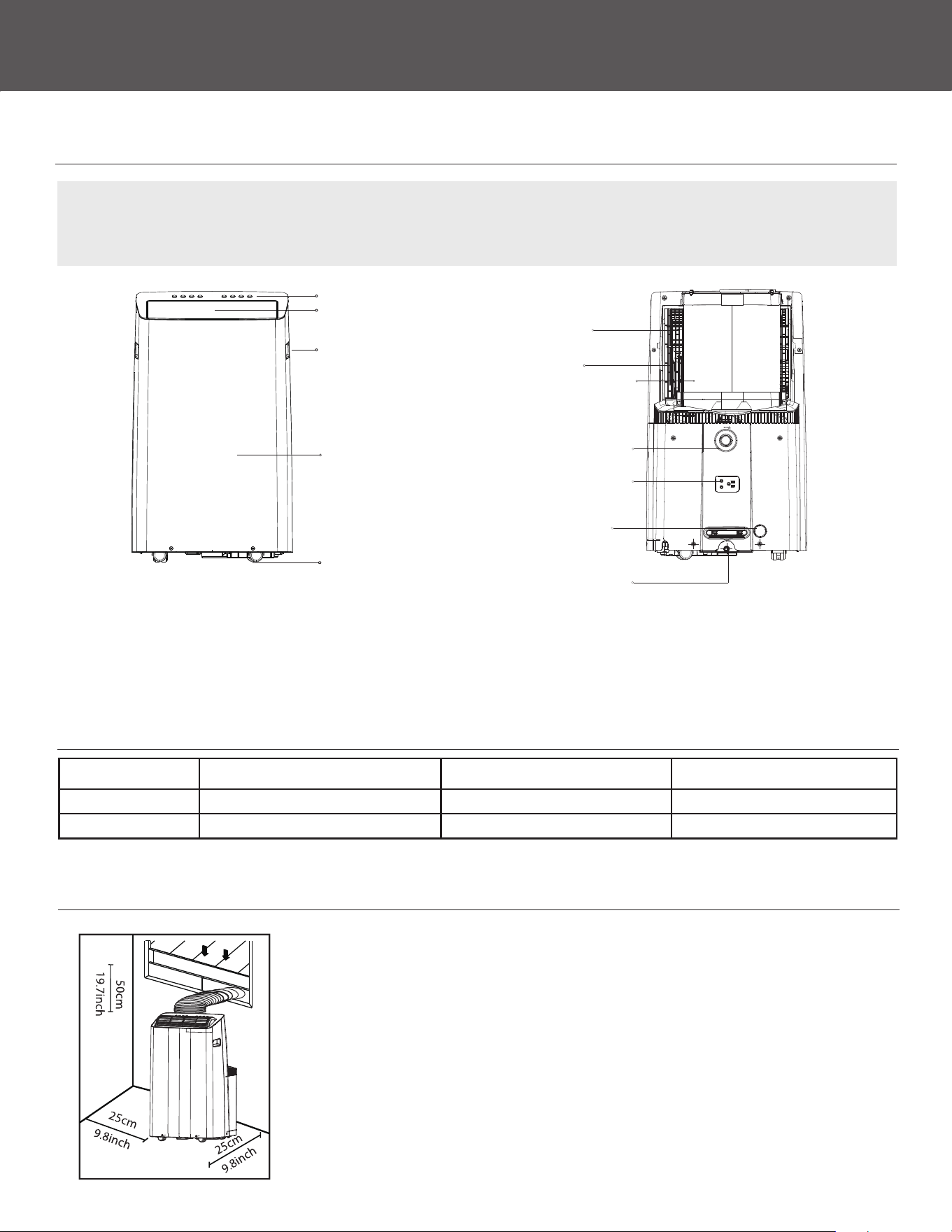
REAR
Power plug socket
Bottom tray
drain outlet
Drain outlet
(only for pump
heating mode)
Upper air lter
(behind the grille)
Upper air intake
Air hose
Drain outlet
FRONT
Control panel
Handle
(both sides)
Horizontal louver blade
(swing automatically)
Caster
Panel
AMBIENT TEMPERATURE RANGE FOR UNIT OPERATING
Mode Temperature Range Mode Temperature Range
Cool 16-35°C (60-95°F) Heat (pump heat mode) 5-30°C (41-86°F)
Dry 13-35°C (55-95°F) Heat (electrical heat mode)) 30°C (86°F) ≥
CHOOSING THE RIGHT LOCATION
Your installation location should meet the following requirements:
• Make sure that you install your unit on an even surface to minimize noise and vibration.
• The unit must be installed near a electrical outlet, and the Collection Tray Drain (found on
the back of the unit) must be accessible.
• The unit should be located at least 9.8" from the nearest wall to ensure proper air
conditioning. The horizontal louver blade should be at least 19.7" away from obstacles.
• DO NOT cover the Intakes, Outlets or Remote Signal Receptor of the unit, as this could cause
damage to the unit.
8
SAFETY & PRECAUTIONS
CONTINUEDCONTINUED
INSTALLATION INSTRUCTIONS
(Continued)
TOOLS NEEDED
• Medium Phillips screwdriver
• Fine-toothed saw
(Optional, to shorten window slider for narrow windows)
• Tape measure or ruler
• Knife or scissors
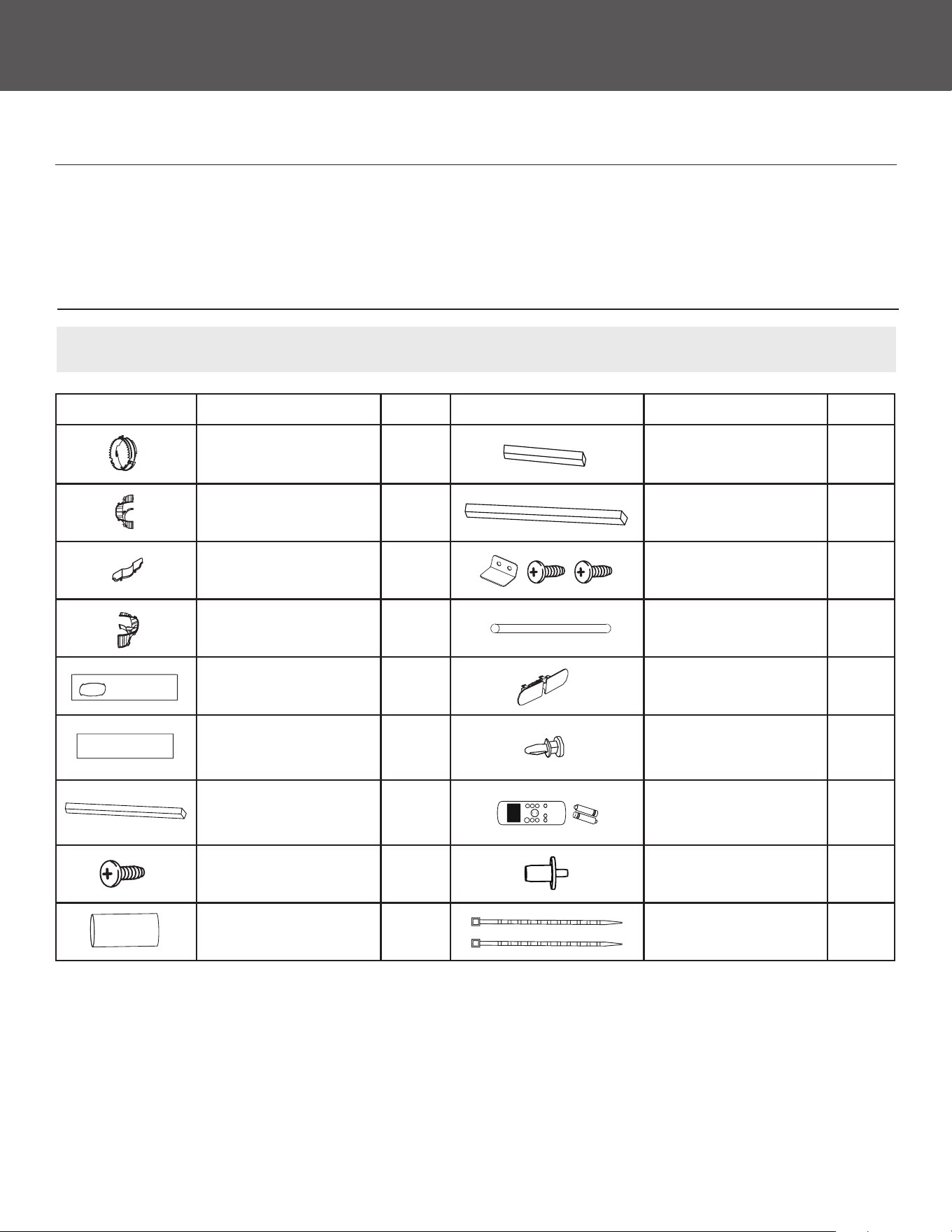
ACCESSORIES
NOTE: Items with (*) are only for some models. Slight variations in design may occur.
Shape Name of Accessories Qty. Shape Name of Accessories Qty.
Anti-hot Air Inlet Adapter 1 pc
Foam Seal B
(Adhesive)
2 pc
Exhaust Adapter
Module A
1 pc (*)
Foam Seal C
(Non-adhesive)
1 pc
Exhaust Adapter
Module B
1 pc (*)
Security Bracket
and 2 Screws
1 set
Exhaust Adapter
Module C
1 pc (*) Drain Hose 1 pc
Window Slider
A
1 pc
Power Cord Buckle
(only for cooling model)
1 pc(*)
Window Slider
B
1 pc Bolt
1 pc
2 pc
3 pc
Foam Seal A
(Adhesive)
1 pc
Remote Controller
and Battery
(only for remote control models)
1 set
1 Screw
(on Exhaust Adapter)
1 pc (*)
Drain Hose Adapter
(only for heat pump model)
1 pc (*)
Air Hose Insulator
(only for heat pump model)
1 pc (*)
Zip Tie
(only for heat pump model)
2 pc (*)
9
INSTALLATION INSTRUCTIONS
(Continued)
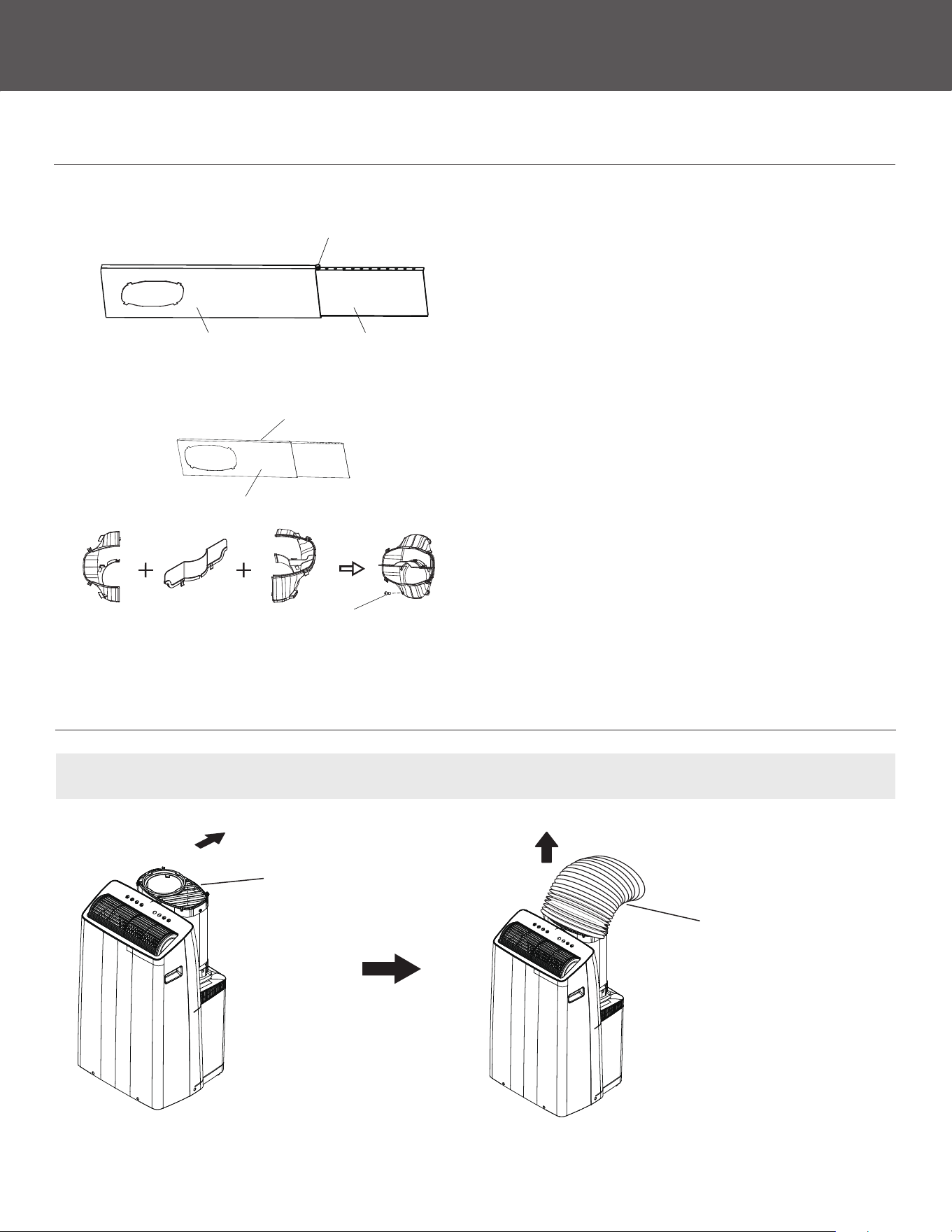
PREPARE THE WINDOW SLIDER KIT
STEP ONE:
Preparing the Adjustable Window Slider
1. Choose the window sliders according the size of
your window. Sometimes, it needs to be cut short to
meet the window size, please take extra care to cut
it properly.
2. Use bolts to fasten the window sliders once they are
adjusted to the Proper length.
STEP TWO:
Preparing the Exhaust Adapter Module
(For Sliding Window)
1. Assemble the Exhaust Adapter Modules for Sliding
Window. Install the Exhaust Adapter Modules with
1 screw as shown. The Exhaust Adapter needs
to be installed on a side away from the wall. See
installation instructions for more detail.
Window slider A Window slider B
Bolt
module B module Cmodule A Exhaust Adaptor
1 screw
outside
inside
PREPARE THE AIR HOSE
NOTE: Rotate the air hose gently backwards, then pull out the air hose as you need.
Unclip the hose before
rotating the air hose
gently backwards
Pull out the air hose
10
SAFETY & PRECAUTIONS
CONTINUEDCONTINUED
INSTALLATION INSTRUCTIONS
(Continued)
AIR HOSE INSULATOR INSTALLATION (FOR HEAT PUMP MODE)
NOTE: When the unit is at heat mode, the Air Hose insulator must be xed in the hose of unit.
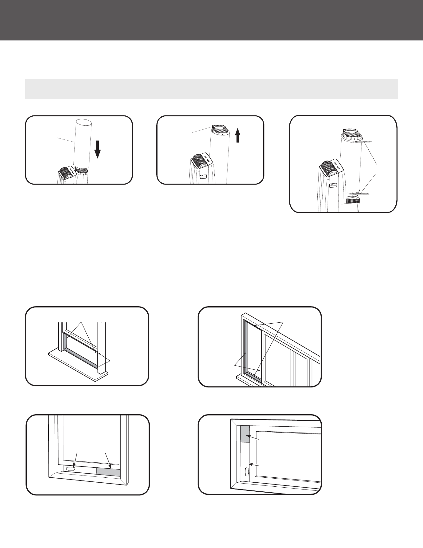
INSTALLATION
Once the Exhaust Hose assembly and Adjustable Window Slider are prepared you may install the unit. Options for casement and slider
window installation are shown.
Air hose insulator
Foam seal B
(Adhesive type-shorter)
Foam seal A
(Adhesive type)
Window
slider A
Window
slider B
(if required)
Foam seal B
(Adhesive type-shorter)
Foam seal A
(Adhesive type)
Window slider A
Window slider B
(if required)
hose
Zip Ties
3. Tighten the air hose with the
1. Cover the air hose with the
air hose insulator.
2. Pull out the air hose and cut
the useless part of the air hose
insulator.
3. Tighten the air hose insulator with
the zip ties and cut extra length
OR
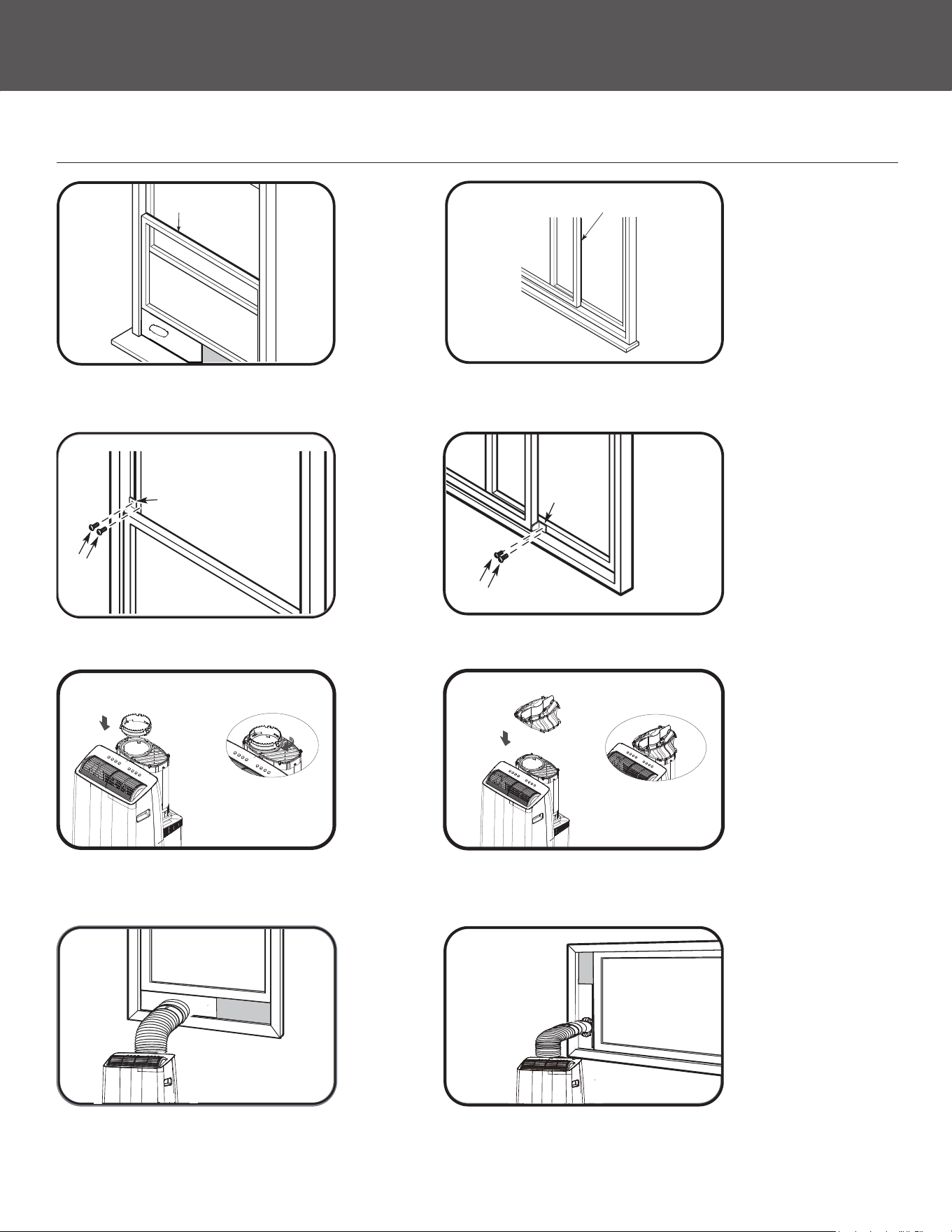
1. Cut the adhesive foam seal A and B strips to the proper lengths and attach them to the window sash and frame as shown.
2. Insert the window slider assembly into the window opening.
OR
11
INSTALLATION INSTRUCTIONS
(Continued)
INSTALLATION
3. Cut the non-adhesive foam seal C strip to match the width (or height) of the window. Insert the seal between the glass and the
window frame to prevent air and insects from getting into the room.
4. If desired, install the security bracket with 2 screws as shown.
5. Insert the Anti-hot Air Inlet Adapter into the air hose, then rotate 90° clockwise for hung window. For Sliding windows, insert the
Exhaust Adapter to the air hose.
6. Insert the air hose into the hole of the window slider for hung window. For Sliding Window the window slider hole is not in the
center, so the exhaust adapter is installed away from the wall. Then Insert the exhaust adapter into the hole of the window slider.
2
Screws
Security Bracket
Foam seal C
(Non-adhesive type)
1 2
Foam seal C
(Non-adhesive type)
2
Screws
Security
Bracket
1 2
OR
OR
OR
OR
12
SAFETY & PRECAUTIONS
CONTINUEDCONTINUED
OPERATING INSTRUCTIONS
(Continued)
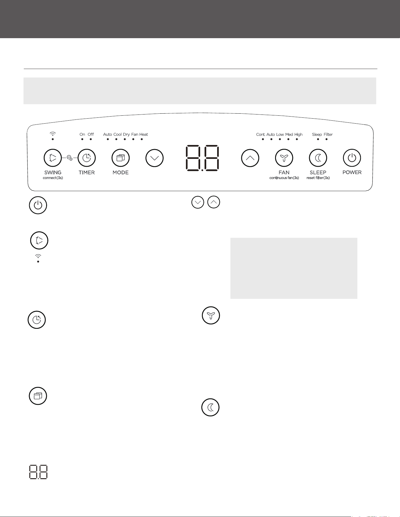
CONTROL PANEL
NOTE: The following control panels are for explanation purpose only. The control panel of the unit you purchased may be
slightly dierent according to the models.
POWER
Switch on/o.
SWING/Wireless
Also used to initiate the Wireless function. See
the included Mobile App Manual for more detail
on how to connect your unit to the wireless app.
Used to initiate the Auto swing feature. When
the operation is ON, press the SWING button to
stop the louver at the desired angle.
TIMER
Used to initiate the AUTO ON start time and
AUTO OFF stop time, in conjunction with the
UP & DOWN buttons. The timer on/o indicator
light illuminates under the timer on/ o
settings. Press and hold on TIMER button for 3
seconds to cancel timer function.
MODE
Selects the appropriate operating mode. Each
time you press the button, a mode is selected in
a sequence that goes from AUTO, COOL, DRY,
FAN and HEAT (cooling only models without).
The mode indicator light illuminates under the
dierent mode settings.
LED display
Shows the set temperature and Auto-timer
settings. While in FAN mode, it shows the room
temperature.
Up and Down buttons
Used to adjust (increasing/decreasing)
temperature settings in 1°F increments in a
range of 60°F to 86°F, or the TIMER setting in a
range of 0~24hrs.
NOTE: The control is capable of
displaying temperature in degrees
Fahrenheit or degrees Celsius. To convert
from one to the other, press and hold the
Up and Down buttons at the same time for
3 seconds.
FAN/Continuous fan
Press to select the fan speed in four steps-
AUTO, LOW, MED, and HIGH. The fan speed
indicator light illuminates under dierent
fan settings. NOTE: The fan speed cannot be
selected in AUTO or DRY mode. On cool or dry
mode, press and hold FAN button for 3 seconds
to initiate continuous fan feature. Press and
hold FAN button for 3 seconds again to stop.
SLEEP
Press SLEEP button to initiate SLEEP mode.
Press SLEEP button again to stop SLEEP mode.
Press SLEEP button for 3 seconds to initiate the
lter feature. This feature is a reminder to clean
the Air Filter for more ecient operation. The
LED light above the button will illuminate after
250 hours of operation.
(3 seconds)
Continuous Fan
(Press 3 seconds)
13
OPERATING INSTRUCTIONS
(Continued)
COOL mode
• Press the “MODE” button until the “COOL” indicator light
comes on.
• Press the ADJUST buttons “UP” or “DOWN” to select your
desired room temperature. The temperature can be set within
a range of 16°C/60°F to 30°C/86°F.
• Press the “FAN SPEED” button to choose the fan speed.
HEAT mode
• Press the “MODE” button until the “HEAT” indicator light
comes on.
• Press the ADJUST buttons “UP” or “ DOWN” to select your
desired room temperature. The temperature can be set within
a range of 60°F to 86°F.
• Press the “FAN SPEED” button to choose the fan speed.
DRY mode
• Press the “MODE” button until the “DRY” indicator light comes
on.
• You cannot select a fan speed in DRY mode. The fan motor
operates at AUTO speed.
• Keep windows and doors closed for the best dehumidifying
eect.
• Do not install the window duct in DRY mode.
AUTO mode
• When you set the air conditioner in AUTO mode, it will
automatically select cooling, heating, or fan only operation
depending on the temperature you selected and the room
temperature.
• The air conditioner will control room temperature automatically
based on the temperature point set.
• You can not select the fan speed in AUTO mode.
OPERATION INSTRUCTIONS
14
ERROR CODES AND PROTECTION CODE:
The unit may stop operation or continue to run safely. If the
errorcodes appear, wait for about 10 minutes. The problem may
resolve itself. If not, disconnect the power, then connect it again.
Turn the unit on. If the problem persists, disconnect the power
and contact your nearest customer service center.
NOTE: When one of the above malfunctions occurs,
turn o the unit, and check for any qualied obstructions.
Restart the unit, if the malfunction is still present, turn
o the unit and unplug the power cord. Contact the
manufacturer or its service agents or a similar quailed
person for service.

SAFETY & PRECAUTIONS
CONTINUEDCONTINUED
OPERATING INSTRUCTIONS
(Continued)
FAN mode
• Press the MODE button until the FAN indicator light comes on.
• Press the FAN SPEED button to choose the fan speed. The
temperature can not be adjusted.
• Do not install the window duct in FAN mode.
TIMER
• When the unit is on, press the Timer button to initiate
the Auto-o program, the TIMER OFF indicator light will
illuminate. Press the UP or DOWN button to select the
desired time. Press the TIMER button again within 5 seconds
to initiate the Auto-on program is initiated. The TIMER ON
indicator will illuminate. Press the UP or DOWN button to
select the desired Auto-on start time.
• When the unit is o, press the TIMER button to initiate the
Auto-on start program. Press it again within 5 seconds to
initiate the Auto-o program.
FOLLOW ME mode
To activate the Follow Me/Temp Sensing feature, point the
remote control towards the unit and press the Follow Me/Temp
Sensing button. The remote control will send this signal to the
air conditioner until press the Follow Me/Temp Sensing button
again. If the unit does not receive the Follow Me remote signal
during any 7 minute interval, the unit will exit Follow Me mode.
• Press or hold the UP or DOWN button to change the Auto
time by 0.5 hour increments, up to 10 hours, then at 1 hour
increments between 11-24 hours. The control panel screen
will count down the time remaining until it re-starts.
• The system will automatically revert back to display the
previous temperature setting if there is no operation in a 5
second period.
• Turning the unit ON or OFF at any time or adjusting the timer
setting to 0.0 will cancel the Auto Start/ Stop timer program.
SLEEP mode
• The selected temperature will increase (cooling) or decrease
(heating) by 2°F after 30 minutes. The temperature will then
increase (cooling) or decrease (heating) by another 2°F
after an additional 30 minutes. This new temperature will
be maintained for 7 hours before it returns to the originally
selected temperature. The unit will continue to operate as
originally programmed.
AUTO-RESTART
If the unit turns o unexpectedly due to the power cut, it will
restart with the previous function setting automatically when
the power resumes.
Air ow direction adjustment
The louver can be adjusted automatically. Adjust the air ow
direction automatically:
• When the Power is ON, the louver opens fully.
• Press the SWING button on the panel or remote controller to
initiate the Auto swing feature. The louver will swing up and
down automatically.
• Please do not adjust the louver manually.
OPERATION INSTRUCTIONS
ADDITIONAL FEATURES
NOTE:
This feature is unavailable under FAN or DRY mode.
NOTE: This feature can be only activated from the remote
control. There is no indicator light on the control panel. The
remote control serves as a remote thermostat, allowing for
precise temperature control at its location.
NOTE:
This feature is unavailable under FAN or DRY mode.
NOTE: After the unit has stopped, it can not be restarted
for 3 minutes. This is to protect the unit. If you press the
power button during this period the unit will wait to start
after 3 minutes have passed.
15
OPERATING INSTRUCTIONS
(Continued)
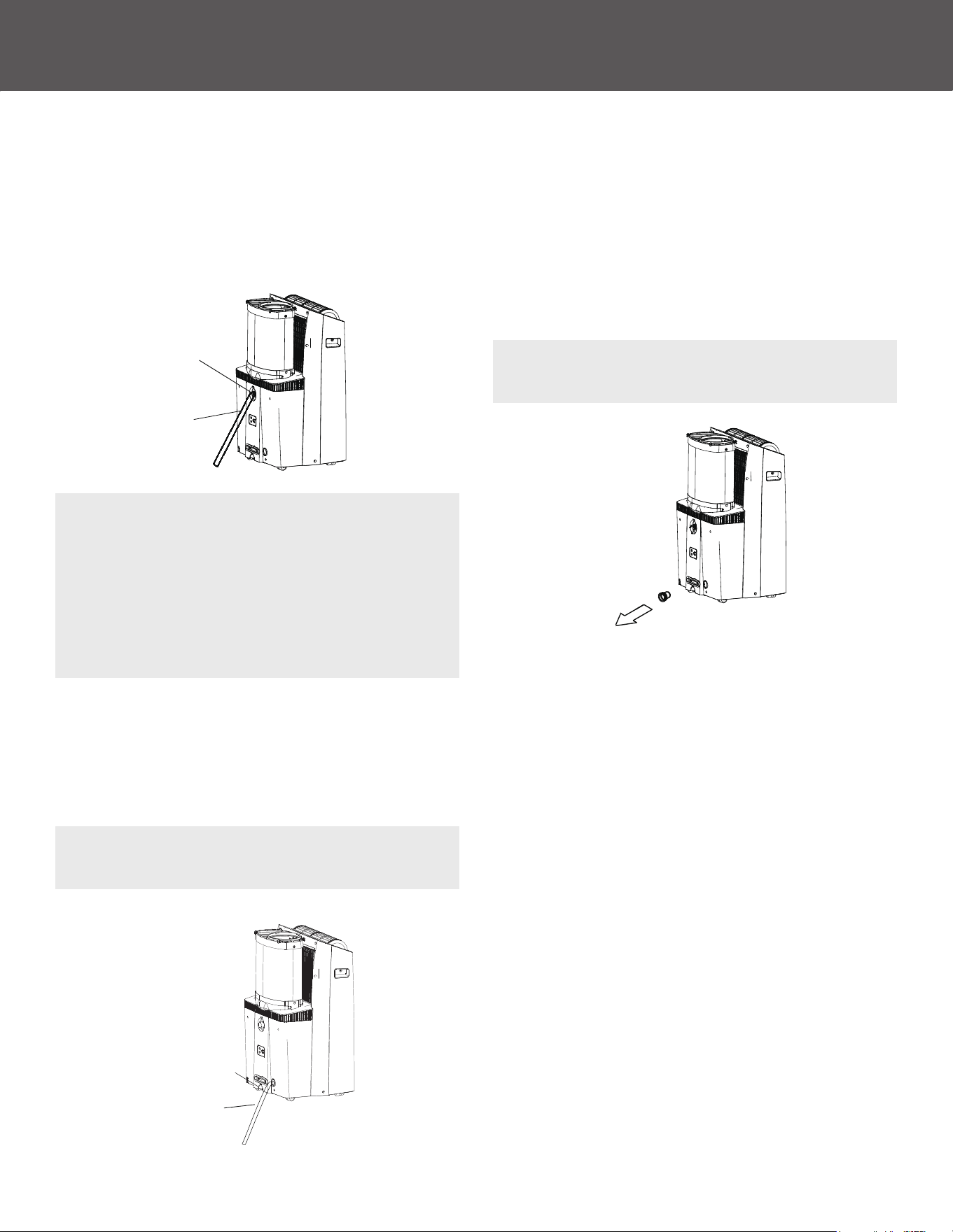
Continuous drainage
• During dehumidifying mode, remove the upper drain plug
from the back of the unit, install the drain connector (5/8"
universal female connector) to 3/4" hose (not included). For
the models without drain connector, just attach the drain hose
to the hole. Place the open end of the hose directly over a
oor drain.
• During heating mode, remove the lower drain plug from the
back of the unit, install the drain connector (5/8" universal
female connector) with 3/4" hose (locally purchased). For the
models without drain connector, just attach the drain hose to
the hole. Place the open end of the Hose adapter directly over
a oor drain.
Regular drainage
• When the water level of the bottom tray reaches a
predetermined level, the unit beeps 8 times and the
digital display area shows “P1”. The air conditioning/
dehumidication process will immediately stop, however, the
fan motor will continue to operate (this is normal). Carefully
move the unit to a drain location, remove the bottom drain
plug and let the water drain away. Reinstall the bottom
drain plug and restart the machine until the “P1” symbol
disappears. If the error repeats, call for service.
NOTE: Be sure to reinstall the bottom drain plug rmly to
prevent leakage before using the unit.
NOTE: Make sure the hose is secure so there are no leaks.
Direct the hose toward the drain, making sure that there
are no kinks that will stop the water owing. Place the end
of the hose into the drain and make sure the end of the
hose is angled down to let the water ow smoothly. When
the continuous drain hose is not used, ensure that the
corresponding drain plug and knob are installed rmly to
prevent leakage.
NOTE: Make sure the drain hose is lower than the bottom
tray drain outlet.
Continuous
drain hose
Remove the
lower drain plug
Remove the
upper drain plug
Continuous
drain hose
16
SAFETY & PRECAUTIONS
CONTINUEDCONTINUED
MAINTENANCE
(Continued)
• Always unplug the unit before cleaning or servicing.
• DO NOT use ammable liquids or chemicals to clean the unit.
• DO NOT wash the unit under running water. Doing so causes
electrical danger.
• DO NOT operate the machine if the power supply was
damaged during cleaning. A damaged power cord must be
replaced with a new cord from the manufacturer.
SAFETY PRECAUTIONS
DO NOT operate the unit without lter because
dirt and lint will clog it and reduce performance.
CAUTION
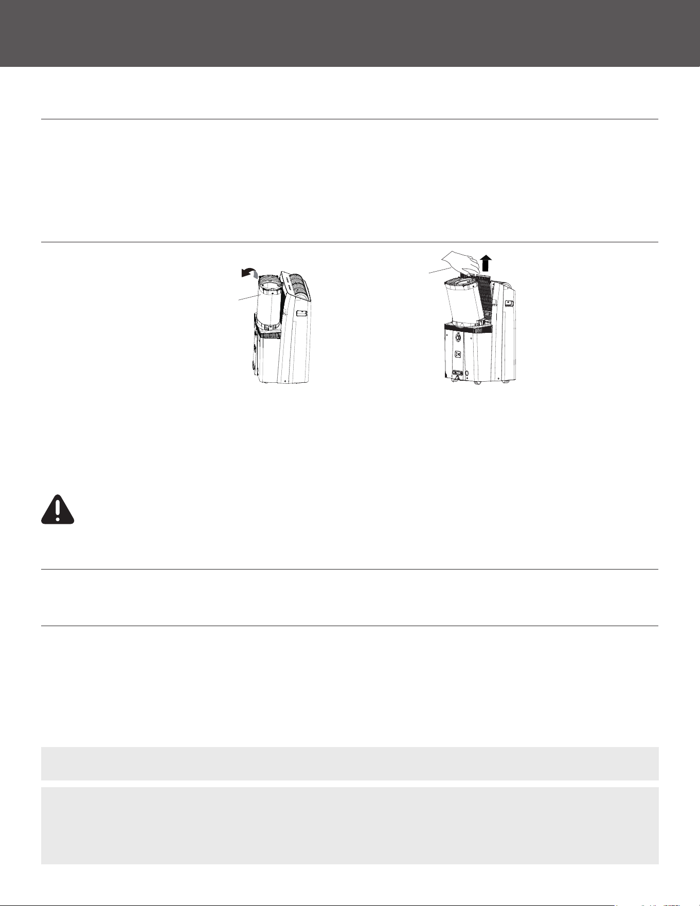
AIR FILTER CLEANING
Maintenance Tips
• Be sure to clean the air lter every 2 weeks for optimal performance.
• The water collection tray should be drained immediately after P1 error occurs, and before storage to prevent mold.
• In households with animals, you will have to periodically wipe down the grill to prevent blocked airow due to animal hair.
• Filter can be cleaned with mild detergent/water or cleaned with a vacuum adapter.
Hold and push backward
slightly, then lift it up.
Unclip hose from back
of unit.
Upper lter
Upper lter
(take out)
UNIT CLEANING
Clean the unit using a damp, lint-free cloth and mild detergent. Dry the unit with a dry, lint-free cloth.
STORAGE WHEN NOT IN USE
• Drain the unit’s water collection tray according to the instructions in the following section.
• Run the appliance on FAN mode for 12 hours in a warm room to dry it and prevent mold.
• Turn o the appliance and unplug it.
• Clean the air lter according to the instructions in the previous section. Reinstall the clean, dry lter before storing.
• Remove the batteries from the remote control.
NOTE:
Be sure to store the unit in a cool, dark place. Exposure to direct sunshine or extreme heat can shorten the lifespan of the unit.
NOTE: The cabinet and front may be dusted with an oil-free cloth or washed with a cloth dampened in a solution of warm water
and mild-liquid dish-washing detergent. Rinse thoroughly and wipe dry. Never use harsh cleansers, wax or polish on the cabinet
front. Be sure to wring excess water from the cloth before wiping around the controls. Excess water in or around the controls may
cause damage to the unit.
17
TROUBLESHOOTING TIPS
(Continued)
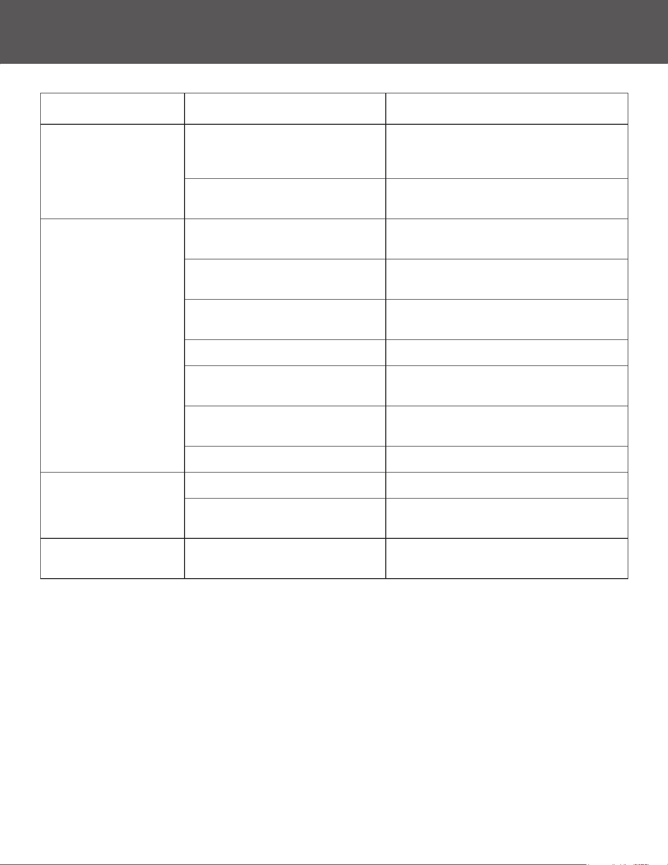
Problem Possible Causes Solution
Unit does not turn on
when pressing ON/OFF
button
P1 Protection Code
The Water Collection Tray is full. Turn o the
unit, drain the water from the Water Collection
Tray and restart the unit.
In COOL mode: Room temperature is
lower than the set temperature
Reset the temperature
Unit does not cool well
Unit will also not cool well
if it is being used in an
uninsulated room
The air lter is blocked with
dust or animal hair
Turn o the unit and clean the lter
according to instructions
Exhaust hose is not connected
or is blocked
Turn o the unit, disconnect the hose, check
for blockage and reconnect the hose
The unit is low on refrigerant
Call a service technician to inspect
the unit and top o refrigerant
Temperature setting is too high Decrease the set temperature
The windows and doors
in the room are open
Make sure all windows and doors are closed
The room area is too large, too small,
or uninsulated
Double-check the cooling area
There are heat sources inside the room Remove the heat sources if possible
The unit is noisy and
vibrates too much
The ground is not level Place the unit on a at, level surface
The air lter is blocked with
dust or animal hair
Turn o the unit and clean the lter
according to instructions
The unit makes a
gurgling sound
This sound is caused by the ow
of refrigerant inside the unit
This is normal
18


844-4PA-AIRE | 844-472-2473 | support@perfectaire.us
CANADA SUPPORT 877-997-2473 | supportcanada@perfectaire.us
www.perfectaire.us
5401 Dansher Road
Countryside, IL 60525
Printed in China | 0321_M699