
Loading ...
Loading ...
Loading ...
5.
Mark the gang box screw holes on the wall.
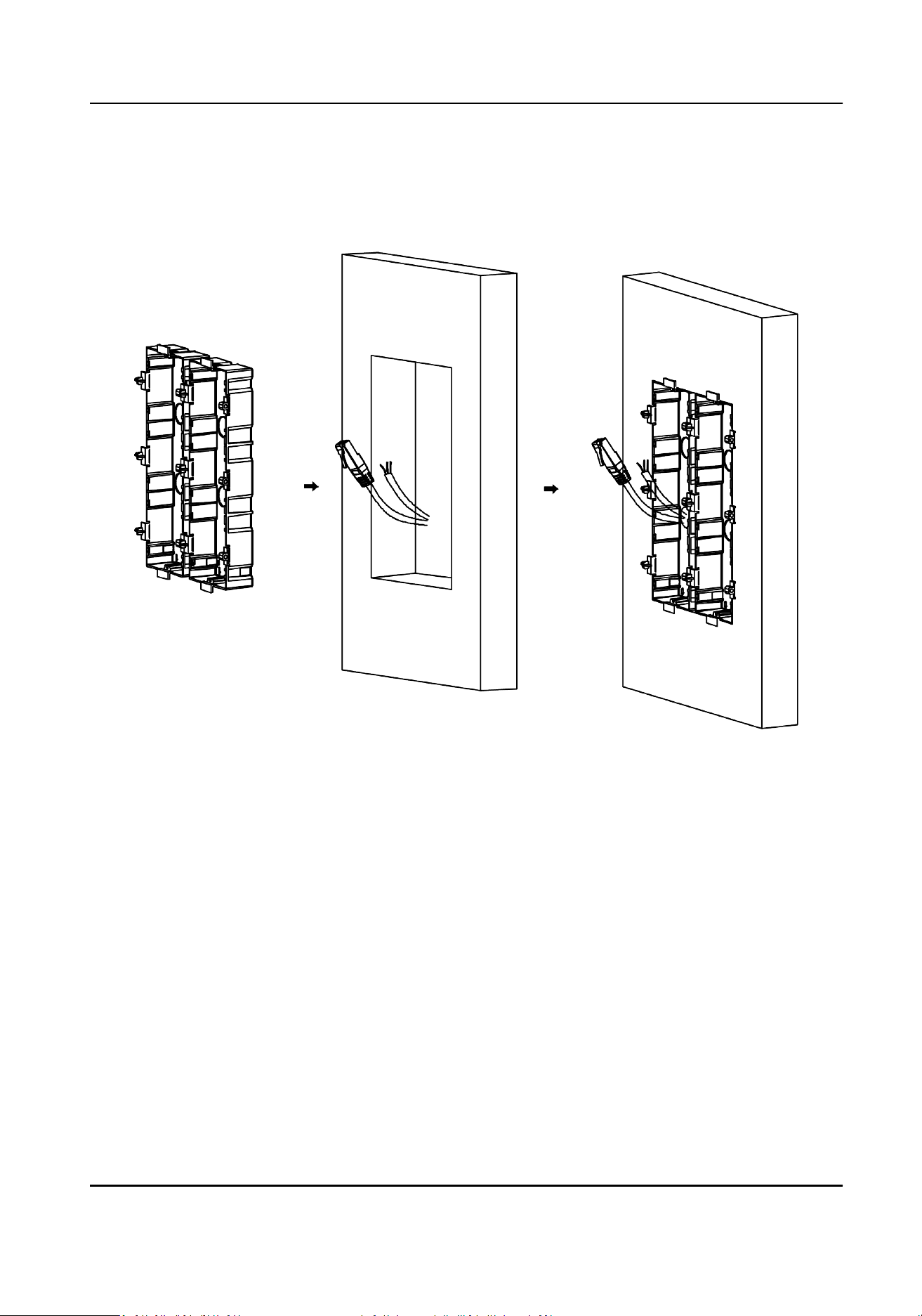
1) Route the cables through the gang box hole.
2) Insert the gang box into the installaon hole.
3) Mark the gang box screw holes' posion with a marker, and take out the gang box.
Figure 4-56 Mark the Screw Holes
6.
Drill 8 holes according to the marks on the wall, and insert the expansion sleeves into the screw
holes. The suggested size of hole is 6 (diameter) × 45 (depth) mm.
7.
Fix the gang boxes with 8 expansion bolts.
DS-KD8003 Series Module Door Staon User Manual
61
Loading ...
Loading ...
Loading ...