-2-
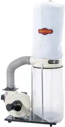
Model W1666 (Mfd. Since 06/22)
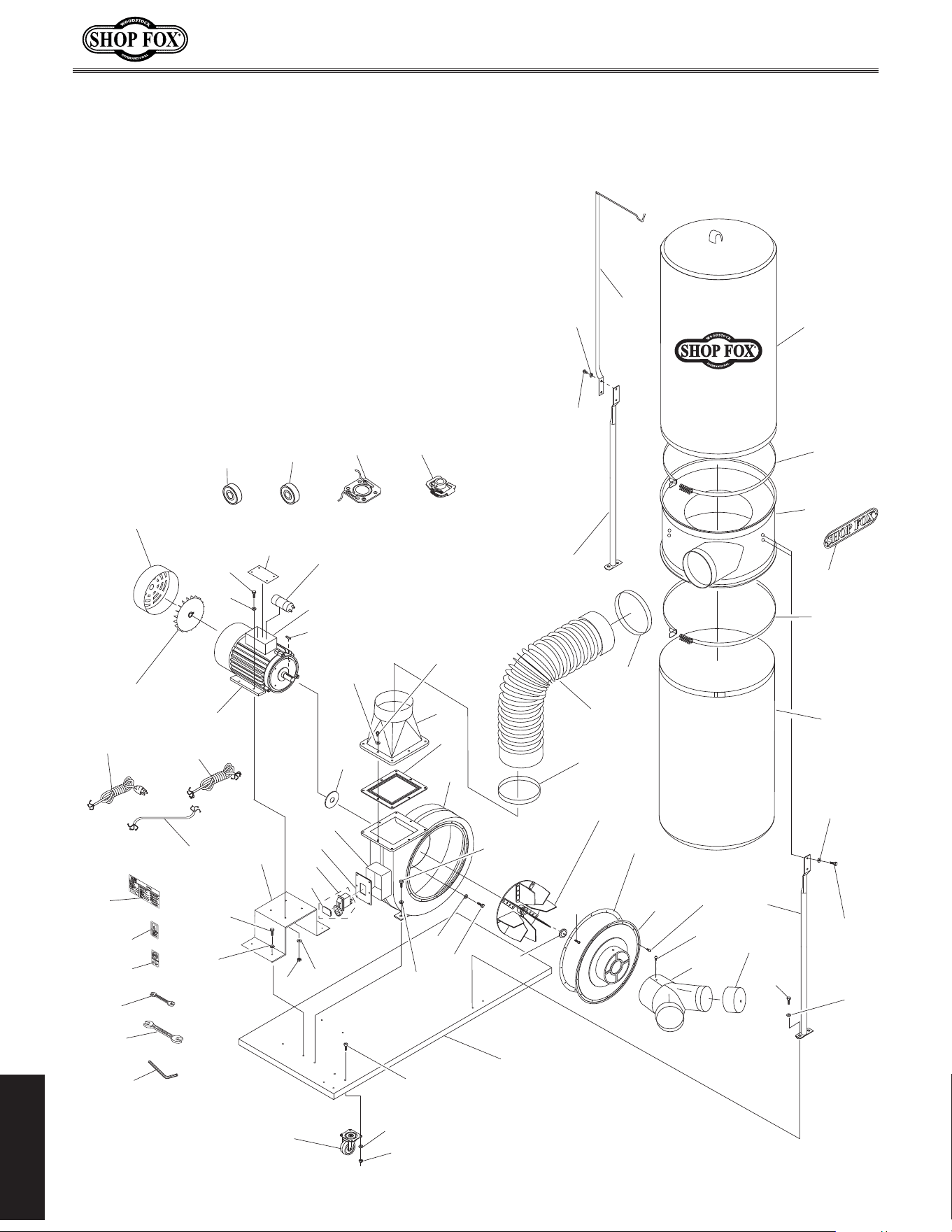
PARTS
PARTS
(Replaces Page 37 in Manual)
PARTS
Main
1
19
4
5
6(W1666)
50(W1685)
16(W1666)
4(W1685)
49
2
24B
18
38-1
38-2
9
20
21
23
3
23
24A
38-3
25A
26
27
22B (W1666)
22 (W1685)
38
31
29
30
16
6
42
12
32
43
31
39
40
14
8A-1 (W1666)
8-1 (W1685)
8-5
8-3
8-4
8-14
8-13
15
13
8-6 (W1666)
8A-2 (W1685)
8-11 (W1666)
8A-1 (W1685)
8A
17
36
34V2
33
33-1
35
34V2
14
48
49
8-10
7-1
7 (W1685)
7 (W1666)
41
10
16
6
6
16
6
16
6
16
-3-
Model W1666 (Mfd. Since 06/22)
PARTS
PARTS
(Replaces Page 38 in Manual)
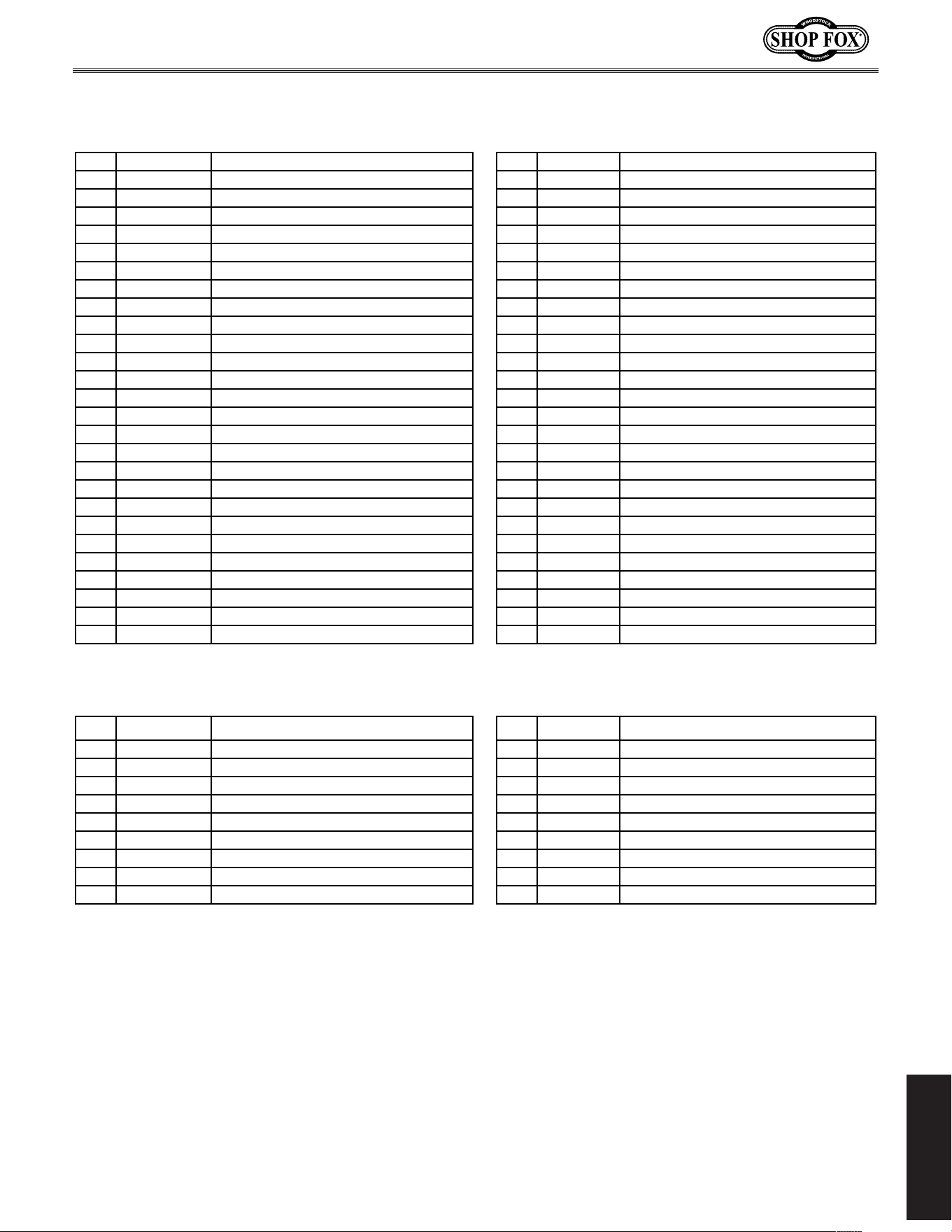
Main Parts List
REF PART # DESCRIPTION REF PART # DESCRIPTION
1 X1666001 SWIVEL CASTER 26 X1666026 CAP SCREW M6-1 X 20 LH
2 X1666002 HEX NUT M8-1. 25 27 X1666027 ARBOR WASHER
3 X1666003 BASE PLATE 29A X1666029A OUTLET GASKET 6 HOLE (W1666)
4 X1666004 FLAT WASHER 6MM 29 X1685029 OUTLET GASKET 8 HOLE (W1685)
5 X1666005 MOTOR MOUNT 30A X1666030A OUTLET FLANGE 6 HOLE (W1666)
6 X1666006 HEX BOLT M8-1.25 X 16 30 X1685030 OUTLET FLANGE 8 HOLE (W1685)
7 X1666007 POWER CORD 14G 3W 120" (W1666) 31 X1666031 HOSE CLAMP 5"
7 X1685007 POWER CORD 14G 3W 72" 5-15 (W1685) 32 X1666032 TRANSFER HOSE 5"
7-1 X1666007-1 MOTOR CORD 14G 3W 24" 33 X1666033 SEPARATOR
9 X1666009 SHOP FOX PADDLE SWITCH 110V W/KEY 33-1 X1666033-1 CURVED SHOP FOX NAME PLATE
10 X1666010 PADDLE SWITCH KEY 34V2 X1666034V2 BAG CLAMP POLYPROPYLENE V2.07.10
12 X1666012 HEX WRENCH 5MM 35V2 X1666035V2 UPPER BAG 2.5 MICRON V2.02.15
13 X1666013 UPPER BAG HANGER 36V2 X1666036V2 LOWER BAG (PLASTIC) V2.02.15
14 X1666014 SEPARATOR SUPPORT 38 X1666038 IMPELLER HOUSING (W1666)
15 X1666015 HEX BOLT M8-1.25 X 25 38 X1685038 IMPELLER HOUSING (W1685)
16 X1666016 FLAT WASHER 8MM 38-1 X1666038-1 SWITCH BOX
17 X1666017 KEY 5 X 5 X 25 38-2 X1666038-2 SWITCH BOX COVER
18 X1666018 MOTOR SHAFT SPACER 38-3 X1666038-3 IMPELLER COVER GASKET
19 X1666019 HEX NUT M6-1 39 X1666039 HAND/ I NLET WARNING LABEL
20 X1666020 LOCK WASHER 10MM 40 X1666040 READ MANUAL LABEL
21 X1666021 HEX BOLT M10-1.5 X 16 41 X1666041 MACHINE ID LABEL (W1666)
22B X1666022B IMPELLER (W1666) 41 X1685041 MACHINE ID LABEL (W1685)
22 X1685022 IMPELLER (W1685) 42 X1666042 WRENCH 8 X 10MM OPEN-ENDS
23 X1666023 PHLP HD SCR M6-1 X 10 43 X1666043 WRENCH 11 X 13MM OPEN-ENDS
24A X1666024A INLET Y-CONNECTOR 6" X (2)4" V2.12.01 48 X1666048 PHLP HD SCR M5-.8 X 10
24B X1666024B INLET Y-CONNECTOR CAP 49 X1666049 FLAT WASHER 8MM
25A X1666025A IMPELLER COVER 6" V2.12.01 50 X1685050 HEX BOLT M6-1 X 20
W1666 2 HP, 220V, Single-Phase Motor W1685 1-1/2 HP, 110V, Single-Phase Motor
REF PART # DESCRIPTION REF PART # DESCRIPTION
8A X1666008A MOTOR 2HP 220V 1-PH V2.11.02 8A X1685008A MOTOR 1-1/2HP 110V 1-PH V2.11.02
8-3 X1666008-3 CENTRI FUGAL SWI TCH 8-3 X1685008-3 CENTRI FUGAL SWI TCH
8-4 X1666008-4 CONTACT PLATE 8-4 X1685008-4 CONTACT PLATE
8-5 X1666008-5 MOTOR BOX COVER 8-5 X1685008-5 MOTOR BOX COVER
8-6 X1666008-6 MOTOR FAN COVER 8A-2 X1685008A-2 MOTOR FAN COVER
8-10 X1666008-10 WIRING BOX WITHOUT COVER 8-10 X1685008-10 WIRING BOX WITHOUT COVER
8-11 X1666008-11 MOTOR FAN 8A-1 X1685008A-1 MOTOR FAN
8A-1 X1666008A-1 S CAPACITOR 200M 250V 8-1 X1685008-1 S CAPACITOR 600M 125V
8-13 X1666008-13 BALL BEARING 6203ZZ 8-13 X1685008-13 MOTOR FRONT BEARI NG
8-14 X1666008-14 BALL BEARING 6205ZZ 8-14 X1685008-14 MOTOR REAR BEARING

High Quality Machines and Tools
Woodstock International, Inc. carries thousands of products designed to meet the needs
of today’s woodworkers and metalworkers. Ask your dealer about these fine products:
WHOLESALE ONLY
Phone: (360) 734-3482
Fax: (360) 671-3053
Toll Free Fax: (800) 647-8801
P.O. Box 2309, Bellingham, WA 98227
woodstockint.com
®
OWNER'S MANUAL
(FOR MODELS MANUFACTURED SINCE 02/15)
MODEL W1666/W1685
DUST COLLECTORS
Phone: (360) 734-3482 • Online Technical Support: [email protected]
COPYRIGHT © JUNE, 2000 BY WOODSTOCK INTERNATIONAL, INC., REVISED JULY, 2018 (HE)
WARNING: NO PORTION OF THIS MANUAL MAY BE REPRODUCED IN ANY SHAPE OR FORM WITHOUT
THE WRITTEN APPROVAL OF WOODSTOCK INTERNATIONAL, INC.
V4.07.18
#6941CR Printed in China
This manual provides critical safety instructions on the proper setup,
operation, maintenance, and service of this machine/tool. Save this
document, refer to it often, and use it to instruct other operators.
Failure to read, understand and follow the instructions in this manual
may result in fire or serious personal injury—including amputation,
electrocution, or death.
The owner of this machine/tool is solely responsible for its safe use.
This responsibility includes but is not limited to proper installation in
a safe environment, personnel training and usage authorization,
proper inspection and maintenance, manual availability and compre-
hension, application of safety devices, cutting/sanding/grinding tool
integrity, and the usage of personal protective equipment.
The manufacturer will not be held liable for injury or property
damage from negligence, improper training, machine modifications or
misuse.
Some dust created by power sanding, sawing, grinding, drilling, and
other construction activities contains chemicals known to the State of
California to cause cancer, birth defects or other reproductive harm.
Some examples of these chemicals are:
• Lead from lead-based paints.
• Crystalline silica from bricks, cement and other masonry products.
• Arsenic and chromium from chemically-treated lumber.
Your risk from these exposures varies, depending on how often you
do this type of work. To reduce your exposure to these chemicals:
Work in a well ventilated area, and work with approved safety equip-
ment, such as those dust masks that are specially designed to filter
out microscopic particles.

SET UPELECTRICAL MAINTENANCE
SERVICE PARTS
OPERATIONS
SAFETYINTRODUCTION
USE THE QUICK GUIDE PAGE LABELS TO SEARCH OUT INFORMATION FAST!
INTRODUCTION......................................2
Woodstock Technical Support .................. 2
W1666 Machine Specification ................. 3
W1685 Machine Specification ................. 5
SAFETY................................................7
Standard Machinery Safety Instructions ...... 7
Additional Safety for Dust Collectors ......... 9
ELECTRICAL........................................ 10
Circuit Requirements .......................... 10
Grounding Requirements ...................... 11
Extension Cords ................................ 11
SETUP............................................... 12
Unpacking ....................................... 12
Inventory ........................................ 12
Assembly ......................................... 13
Test Run ................................ .......... 18
DESIGNING.THE.SYSTEM......................... 19
General .......................................... 19
Duct Material ................................... 19
System Grounding .............................. 22
System Design .................................. 23
OPERATIONS....................................... 29
General .......................................... 29
Disabling Switch ................................ 29
Machine Storage ................................ 29
ACCESSORIES....................................... 30
MAINTENANCE..................................... 32
General .......................................... 32
Lubrication ...................................... 32
Bag Cleaning .................................... 32
Replacing Bags .................................. 33
SERVICE............................................. 34
Troubleshooting ................ ................. 34
Electrical Safety Instructions ................. 35
Wiring Diagrams ................................ 36
PARTS............................................... 37
WARRANTY......................................... 41
Contents

-2-
Model W1666/W1685 (For Machines Mfd. Since 2/15)
INTRODUCTI ON
Woodstock.Technical .Support
Woodstock International, Inc. is committed to customer satisfaction. Our intent with this manual is to
include the basic information for safety, setup, operation, maintenance, and service of this product.
In the event that questions arise about your machine, please contact Woodstock International Technical
Support at (360).734 -3482 or send e-mail to: tech-support@shopfox.biz. Our knowledgeable staff will
help you troubleshoot problems or process warranty claims.
INTRODUCTI ON
If you need the latest edition of this manual, you can download it from http://www.shopfox.biz.
If you have comments about this manual, please contact us at:
Woodstock.International,.Inc.
Attn:.Technical.Documentation.Manager
P.O..Box.2309
Bellingham,.WA.98227
Email:.manuals @woodstockint.com

-3-
Model W1666/W1685 (For Machines Mfd. Since 2/15)
INTRODUCTI ON
Model W1666 Machine Specifications, Page 1 of 2
MODEL W1666
2 HP DUST COLLECTOR
Product Dimensions
Weight........................................................................................................... 92 lbs.
Width (side‐to‐side) x Depth (front‐to‐back) x Height.............................. 33‐1/2 x 21‐1/2 x 78 in.
Footprint (Length x Width).................................................................... 33‐1/2 x 21‐1/2 in.
Shipping Dimensions
Type.................................................................................................... Cardboard Box
Content........................................................................................................ Machine
Weight.......................................................................................................... 108 lbs.
Length x Width x Height........................................................................... 36 x 23 x 23 in.
Must Ship Upright.................................................................................................. Yes
Electrical
Power Requirement.................................................................... 220V, Single‐Phase, 60 Hz
Prewired Voltage................................................................................................. 220V
Full‐Load Current Rating......................................................................................... 12A
Minimum Circuit Size............................................................................................. 15A
Connection Type......................................................................................... Cord & Plug
Power Cord Included.............................................................................................. Yes
Power Cord Length.............................................................................................. 10 ft.
Power Cord Gauge............................................................................................ 14 AWG
Plug Included........................................................................................................ No
Recommended Plug Type........................................................................................ 6‐15
Switch Type............................................................ Paddle Safety Switch w/Removable Key
Motors
Main
Horsepower................................................................................................. 2 HP
Phase.............................................................................................. Single‐Phase
Amps.......................................................................................................... 12A
Speed.................................................................................................. 3450 RPM
Type......................................................................... TEFC Capacitor‐Start Induction
Power Transfer ................................................................................... Direct Drive
Bearings................................................................. Sealed & Permanently Lubricated
Centrifugal Switch/Contacts Type................................................................. External

-4-
Model W1666/W1685 (For Machines Mfd. Since 2/15)
INTRODUCTI ON
Model W1666 Machine Specifications, Page 2 of 2
Main Specifications
Operation
Dust Collector Type.............................................................................. Single‐Stage
Approved Dust Types.................................................................................... Wood
Filter Type................................................................................................... Bag
Airflow Performance................................................................................ 1550 CFM
Max Static Pressure (at 0 CFM)...................................................................... 12.3 in.
Main Inlet Size............................................................................................. 6 in.
Inlet Adapter Included..................................................................................... Yes
Number of Adapter Inlets.................................................................................... 2
Adapter Inlet Size......................................................................................... 4 in.
Machine Collection Capacity At One Time................................................................. 3
Maximum Material Collection Capacity......................................................... 5.4 cu. ft.
Filtration Rating.................................................................................... 2.5 Micron
Bag Information
Number of Upper Bags........................................................................................ 1
Number of Lower Bags........................................................................................ 1
Upper Bag Diameter..................................................................................... 19 in.
Upper Bag Length........................................................................................ 33 in.
Lower Bag Diameter..................................................................................... 19 in.
Lower Bag Length........................................................................................ 33 in.
Impeller Information
Impeller Type........................................................................................ Radial Fin
Impeller Size.............................................................................................. 12 in.
Impeller Blade Thickness............................................................................. 3/32 in.
Construction
Upper Bag................................................................................................. Fabric
Lower Bag................................................................................................ Plastic
Base............................................................................. Steel Sheet Metal w/Casters
Caster............................................................................................... Four Plastic
Impeller.................................................................................................... Steel
Paint Type/Finish............................................................................. Powder Coated
Blower Housing............................................................................. Steel Sheet Metal
Body......................................................................................... Steel Sheet Metal
Other
Country of Origin ............................................................................................... China
Warranty ....................................................................................................... 2 Years
Approximate Assembly & Setup Time ................................................................. 45 Minutes
Serial Number Location .................................................................................... ID Label
ISO 9001 Factory .................................................................................................. Yes
Certified by a Nationally Recognized Testing Laboratory (NRTL) .......................................... No
Features
Powder‐Coated Finish
Quick Release Band Clamp
Includes Steel Base with Casters

-5-
Model W1666/W1685 (For Machines Mfd. Since 2/15)
INTRODUCTI ON
Model W1685 Machine Specifications, Page 1 of 2
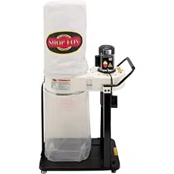
MODEL W1685
11/2 HP DUST COLLECTOR
Product Dimensions
Weight........................................................................................................... 90 lbs.
Width (side‐to‐side) x Depth (front‐to‐back) x Height.............................. 33‐1/2 x 21‐1/4 x 78 in.
Footprint (Length x Width).................................................................... 33‐1/2 x 21‐1/4 in.
Shipping Dimensions
Type.................................................................................................... Cardboard Box
Content........................................................................................................ Machine
Weight.......................................................................................................... 107 lbs.
Length x Width x Height........................................................................... 36 x 23 x 23 in.
Must Ship Upright.................................................................................................. Yes
Electrical
Power Requirement.................................................................... 110V, Single‐Phase, 60 Hz
Prewired Voltage................................................................................................. 110V
Full‐Load Current Rating......................................................................................... 16A
Minimum Circuit Size............................................................................................. 20A
Connection Type......................................................................................... Cord & Plug
Power Cord Included.............................................................................................. Yes
Power Cord Length............................................................................................... 6 ft.
Power Cord Gauge............................................................................................ 14 AWG
Plug Included....................................................................................................... Yes
Recommended Plug Type........................................................................................ 5‐15
Switch Type.............................................................................................. Push Button
Motors
Main
Horsepower.............................................................................................. 1.5 HP
Phase.............................................................................................. Single‐Phase
Amps.......................................................................................................... 16A
Speed.................................................................................................. 3450 RPM
Type......................................................................... TEFC Capacitor‐Start Induction
Power Transfer ................................................................................... Direct Drive
Bearings................................................................. Sealed & Permanently Lubricated
Centrifugal Switch/Contacts Type................................................................. External

-6-
Model W1666/W1685 (For Machines Mfd. Since 2/15)
INTRODUCTI ON
Model W1685 Machine Specifications, Page 2 of 2
Main Specifications
Operation
Dust Collector Type.............................................................................. Single‐Stage
Approved Dust Types.................................................................................... Wood
Filter Type................................................................................................... Bag
Airflow Performance................................................................................ 1280 CFM
Max Static Pressure (at 0 CFM)...................................................................... 10.1 in.
Main Inlet Size............................................................................................. 6 in.
Inlet Adapter Included..................................................................................... Yes
Number of Adapter Inlets.................................................................................... 2
Adapter Inlet Size......................................................................................... 4 in.
Machine Collection Capacity At One Time................................................................. 2
Maximum Material Collection Capacity......................................................... 5.4 cu. ft.
Filtration Rating.................................................................................... 2.5 Micron
Bag Information
Number of Upper Bags........................................................................................ 1
Number of Lower Bags........................................................................................ 1
Upper Bag Diameter..................................................................................... 19 in.
Upper Bag Length........................................................................................ 33 in.
Lower Bag Diameter..................................................................................... 19 in.
Lower Bag Length........................................................................................ 33 in.
Impeller Information
Impeller Type........................................................................................ Radial Fin
Impeller Size.............................................................................................. 12 in.
Impeller Blade Thickness.............................................................................. 1/8 in.
Construction
Upper Bag................................................................................................ Fabric
Lower Bag................................................................................................ Plastic
Base............................................................................. Steel Sheet Metal w/Casters
Caster..................................................................................... High Density Plastic
Impeller.................................................................................................... Steel
Paint Type/Finish............................................................................. Powder Coated
Blower Housing............................................................................. Steel Sheet Metal
Body......................................................................................... Steel Sheet Metal
Other
Country of Origin ............................................................................................... China
Warranty ....................................................................................................... 2 Years
Approximate Assembly & Setup Time ................................................................. 45 Minutes
Serial Number Location .............................................. ID Label Above Magnetic On/Off Switch
ISO 9001 Factory .................................................................................................. Yes
Certified by a Nationally Recognized Testing Laboratory (NRTL) .......................................... No
Features
Large Capacity
Powder‐Coated Finish
Includes Steel Base with Casters

-7-
Model W1666/W1685 (For Machines Mfd. Since 2/15)
SAFETY
Indicates.a.potentially.hazardous.situation.which,.if.not.avoided,.
MAY.result.in.minor.or.moderate.injury.
Indicates.an.imminently.hazardous.situation.which,.if.not.avoided,.
WILL.result.in.death.or.serious.injury.
Indicates.a.potentially.hazardous.situation.which,.if.not.avoided,.
COULD.result.in.death.or.serious.injury.
This.symbol.is.used.to.alert.the.user.to.useful.information.about.
proper.operation.of.the.equipment.or.a.situation.that.may.cause.
damage.to.the.machinery.
NOTICE
SAFETY
OWNER’S.MANUAL..
Read and understand this
owner’s manual BEFORE using machine.
TRAINED.OPERATORS.ONLY..
Untrained operators
have a higher risk of being hurt or killed. Only
allow trained/supervised people to use this
machine. When machine is not being used,
disconnect power, remove switch keys, or
lock-out machine to prevent unauthorized
use—especially around children. Make
workshop kid proof!
DANGEROUS.ENVIRONMENTS..
Do not use
machinery in areas that are wet, cluttered,
or have poor lighting. Operating machinery
in these areas greatly increases the risk of
accidents and injury.
MENTAL.ALERTNESS.REQUIRED..
Full mental
alertness is required for safe operation of
machinery. Never operate under the influence
of drugs or alcohol, when tired, or when
distracted.
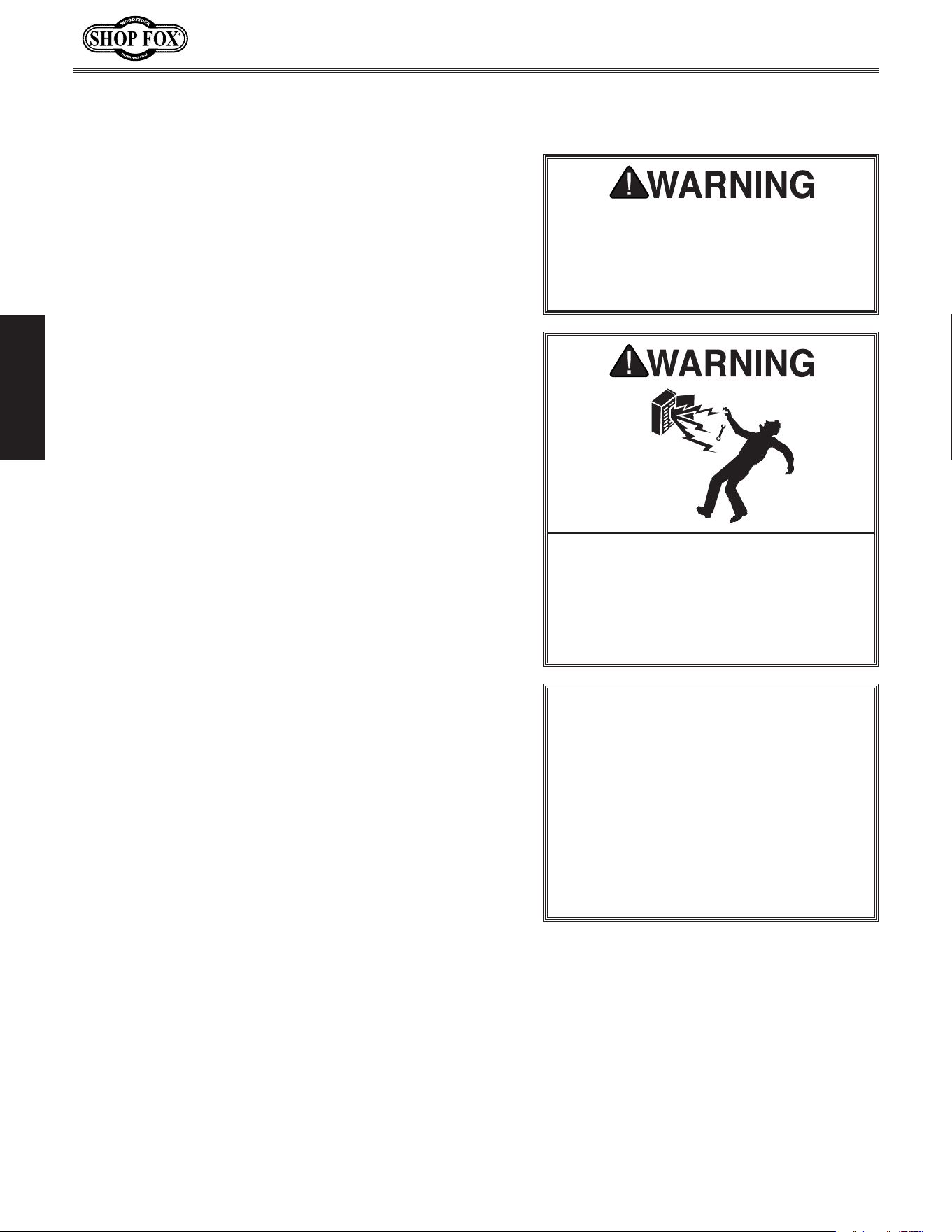
ELECTRICAL.EQUIPMENT.INJURY.RISKS..You can
be shocked, burned, or killed by touching live
electrical components or improperly grounded
machinery. To reduce this risk, only allow an
electrician or qualified service personnel to
do electrical installation or repair work, and
always disconnect power before accessing or
exposing electrical equipment.
DISCONNECT.POWER.FIRST..Always disconnect
machine from power supply BEFORE making
adjustments, changing tooling, or servicing
machine. This eliminates the risk of injury
from unintended startup or contact with live
electrical components.
EYE.PROTECTION..Always wear ANSI-approved
safety glasses or a face shield when operating
or observing machinery to reduce the risk of
eye injury or blindness from flying particles.
Everyday eyeglasses are not approved safety
glasses.
Standard.Machinery.Safety.Instru ctions
For.Your.Own.Safety,
Read.Manual.Befo re.Operating.Machine
The. purpose. of. safety. symbols. is. to. attract. your. attention. to. possible. hazardous. conditions.. This.
manual.uses.a.series.of.symbols.and.signal.words.intended.to.convey.the.level.of.import ance.of.the.
safety.messages..The.progression.of.symbols.is.described.below..Remember.that.safety.messages.by.
themselves. do.not.eliminate. danger.and.are.not.a. substitute. for.proper.accident.prevention.mea-
sures—this.responsibility.is.ultimately.up.to.the.operator!
SAFETY
Standard.Machinery.S afety.Instructions

-8-
Model W1666/W1685 (For Machines Mfd. Since 2/15)
SAFETY
WEARING.PROPER.APPAREL..Do not wear
clothing, apparel, or jewelry that can become
entangled in moving parts. Always tie back
or cover long hair. Wear non-slip footwear to
avoid accidental slips, which could cause loss
of workpiece control.
HAZARDOUS
.DUST..Dust created while using
machinery may cause cancer, birth defects,
or long-term respiratory damage. Be aware of
dust hazards associated with each workpiece
material, and always wear a NIOSH-approved
respirator to reduce your risk.
HEARING.PROTECTION..
Always wear hearing
protection when operating or observing
loud machinery. Extended exposure to this
noise without hearing protection can cause
permanent hearing loss.
REMOVE.ADJUSTING.TOOLS..
Tools left on
machinery can become dangerous projectiles
upon startup. Never leave chuck keys,
wrenches, or any other tools on machine.
Always verify removal before starting!
INTENDED.USAGE..
Only use machine for its
intended purpose—never make modifications
without prior approval from Woodstock
International. Modifying machine or using
it differently than intended will void the
warranty and may result in malfunction or
mechanical failure that leads to serious
personal injury or death!
AWKWARD.POSITIONS..
Keep proper footing and
balance at all times when operating machine.
Do not overreach! Avoid awkward hand
positions that make workpiece control difficult
or increase the risk of accidental injury.
CHILDREN.&.BYSTANDERS..
Keep children and
bystanders at a safe distance from the work
area. Stop using machine if they become a
distraction.
GUARDS.&.COVERS..
Guards and covers reduce
accidental contact with moving parts or flying
debris—make sure they are properly installed,
undamaged, and working correctly.
FORCING.MACHINERY..Do not force machine. It
will do the job safer and better at the rate for
which it was designed.
NEVER.STAND.ON.MACHINE..Serious injury may
occur if machine is tipped or if the cutting
tool is unintentionally contacted.
STABLE.MACHINE..Unexpected movement during
operation greatly increases risk of injury or
loss of control. Before starting, verify machine
is stable and mobile base (if used) is locked.
USE.RECOMMENDED.ACCESSORIES..Consult
this owner’s manual or the manufacturer for
recommended accessories. Using improper
accessories will increase risk of serious injury.
UNATTENDED.OPERATION..To reduce the risk
of accidental injury, turn machine OFF and
ensure all moving parts completely stop
before walking away. Never leave machine
running while unattended.
MAINTAIN.WITH.CARE..Follow all maintenance
instructions and lubrication schedules to
keep machine in good working condition. A
machine that is improperly maintained could
malfunction, leading to serious personal injury
or death.
CHECK.DAMAGED.PARTS..Regularly inspect
machine for any condition that may affect
safe operation. Immediately repair or replace
damaged or mis-adjusted parts before
operating machine.
MAINTAIN.POWER.CORDS..When disconnecting
cord-connected machines from power, grab
and pull the plug—NOT the cord. Pulling the
cord may damage the wires inside, resulting
in a short. Do not handle cord/plug with wet
hands. Avoid cord damage by keeping it away
from heated surfaces, high traffic areas, harsh
chemicals, and wet/damp locations.
EXPERIENCING.DIFFICULTIES..If at any time
you experience difficulties performing the
intended operation, stop using the machine!
Contact Technical Support at (360) 734-3482.

-9-
Model W1666/W1685 (For Machines Mfd. Since 2/15)
SAFETY
Additional.Safety.for.Dust.Collectors
INTENDED USE. This dust collector is only
intended for collecting wood dust and chips
from woodworking machines. DO NOT use this
dust collector to collect metal, dirt, pebbles,
drywall, asbestos, lead paint, silica, liquids,
aerosols, or any flammable, combustible, or
hazardous materials.
HAZARDOUS
DUST. Dust created while using
machinery may cause cancer, birth defects,
or long-term respiratory damage. Be aware of
dust hazards associated with each workpiece
material, and always wear a NIOSH-approved
respirator to reduce your risk.
DUST ALLERGIES
. Dust from certain woods
may cause an allergic reaction in people and
animals. Make sure you know what type of
wood dust you will be exposed to in case
there is a possibility of an allergic reaction.
WEAR RESPIRATOR.
Fine dust that is too small
to be caught in the filter will be blown into
the ambient air during operation. Always wear
a NIOSH approved respirator during operation
and for a short time after to reduce your risk
of permanent respiratory damage.
EMPTYING DUST.
When emptying dust from the
collection container, wear a respirator and
safety glasses. Empty dust away from ignition
sources and into an approved container.
DISCONNECTING POWER SUPPLY.
Turn the
switch OFF, disconnect the dust collector from
the power supply, and allow the impeller to
come to a complete stop before leaving the
machine unattended or doing any service,
cleaning, maintenance, or adjustments.
REGULAR CLEANING.
Regularly check/empty
the collection bags or drum to avoid the
buildup of fine dust that can increase the
risk of fire. Make sure to regularly clean
the surrounding area where the machine is
operated—excessive dust buildup on overhead
lights, heaters, electrical panels, or other
heat sources will increase the risk of fire.
SUSPENDED DUST PARTICLES AND IGNITION
SOURCES. DO NOT operate the dust collector
in areas where explosion risks are high. Areas
of high risk include, but are not limited to,
areas near pilot lights, open flames, or other
ignition sources.
FIRE SUPPRESSION. Only operate dust collector
in locations that contain a fire suppression
system or have a fire extinguisher nearby.
IMPELLER HAZARDS. DO NOT place your hands
or tools near the open inlet during operation
for any reason. The powerful suction could
easily pull them into the impeller, which
will cause serious personal injury or damage
to the machine. Always keep small animals
and children away from open dust collection
inlets.
AVOIDING SPARKS. DO NOT allow steel or rocks
to strike the impeller—this may produce
sparks. Sparks can smolder in wood dust
for a long time before a fire is detected. If
you accidentally cut into wood containing
tramp metal (nails, staples, spikes, etc.),
immediately turn OFF the dust collector,
disconnect it from power, and wait for the
impeller to stop—then empty the collection
container into an approved airtight metal
container.
OPERATING LOCATION. To reduce respiratory
exposure to fine dust, locate permanently
installed dust collectors away from the
working area, or in another room that is
equipped with a smoke detector. DO NOT
operate the dust collector in rainy or wet
locations—exposure to water may create
an shock hazard or decrease the life of the
machine.
STATIC ELECTRICITY. Plastic dust lines generate
high amounts of static electricity as dust
chips pass through them. Although rare,
sparks caused by static electricity can cause
explosions or fire. To reduce this risk, make
sure all dust lines are thoroughly grounded by
using a grounding wire.
-10-
Model W1666/W1685 (For Machines Mfd. Since 2/15)
ELECTRICAL
ELECTRICAL
Circuit.Requirements
This machine must be connected to the correct size and
type of power supply circuit, or fire or electrical damage
may occur. Read through this section to determine if an
adequate power supply circuit is available. If a correct
circuit is not available, a qualified electrician MUST install
one before you can connect the machine to power.
A power supply circuit includes all electrical equipment
between the breaker box or fuse panel in the building
and the machine. The power supply circuit used for
this machine must be sized to safely handle the full-
load current drawn from the machine for an extended
period of time. (If this machine is connected to a circuit
protected by fuses, use a time delay fuse marked D.)
W1685.Circuit.Requirements.for.110V
W1666.Circuit.Requirements.for.220V
Circuit.Type....................... 110V,.60.Hz,.Single-Phase
Circuit.Si ze.............................................. 20.Amps
Plug/Receptacle..................................... NEMA.5-20
Circuit.Type.......................220V,.60.Hz,.Single-Phase
Circuit.Si ze.............................................. 15.Amps
Plug/Receptacle..................................... NEMA.6-15
Full-Load.Current.Rating
The full-load current rating is the amperage a machine
draws at 100% of the rated output power. On machines
with multiple motors, this is the amperage drawn by the
largest motor or sum of all motors and electrical devices
that might operate at one time during normal operations.
W1666.Full-Load.Current.Rating.at.220V.......... 12.Amps
W1685.Full-Load.Current.Rating.at.110V.......... 16.Amps
The. machine.must.be. properly. set. up.
before. it. is. safe. to. operate.. DO. NOT.
connect. this. machine. to. the. power.
source.until.instructed.to.do.so.later.in.
this.manual.
Incorrectly. wiring. or. grounding. this.
machine.can.cause.electrocution,.fire,.
or.machine.damage..To.reduce.this.risk,.
only.an.electrician.or.qualified.service.
personnel. should. do. any. required.
electrical.work.on.this.machine.
NOTICE
The.circuit.requirements.listed.in.this.
manual. apply. to
.a.dedicated.circuit—
where.only.one.machine.will.be.running.
at. a. time.. If. this. machine. will. be.
connected. to. a. shared. circuit. where.
multiple.machines.will.be.running.at.the.
same.time,.consult.with.an.electrician.
to. ensure. that. the. circuit. is. properly.
sized.for.safe.operation.
This machine is prewired to operate on a 110V power
supply circuit that has a verified ground and meets the
following requirements:
This machine is prewired to operate on a 220V power
supply circuit that has a verified ground and meets the
following requirements:
-11-
Model W1666/W1685 (For Machines Mfd. Since 2/15)
ELECTRICAL
Grounding.Requirements
This machine MUST be grounded. In the event of certain
types of
malfunctions or breakdowns, grounding provides
a path of least resistance for electric current
to travel—in
order
to reduce the risk of electric shock.
Improper connection of the equipment-grounding
wire
will
increase
the risk of electric shock. The wire with green
insulation
(with/without yellow stripes) is the equipment-
grounding
wire. If repair or replacement of the power
cord or plug is necessary, do not connect the equipment-
grounding
wire to a live (current carrying) terminal.
Check with a qualified electrician or service personnel
if
you do not understand these grounding requirements,
or if
you are in doubt about whether the tool is
properly grounded.
If you ever notice that a cord or
plug is damaged or worn, disconnect it from power, and
immediately replace it with a new one.
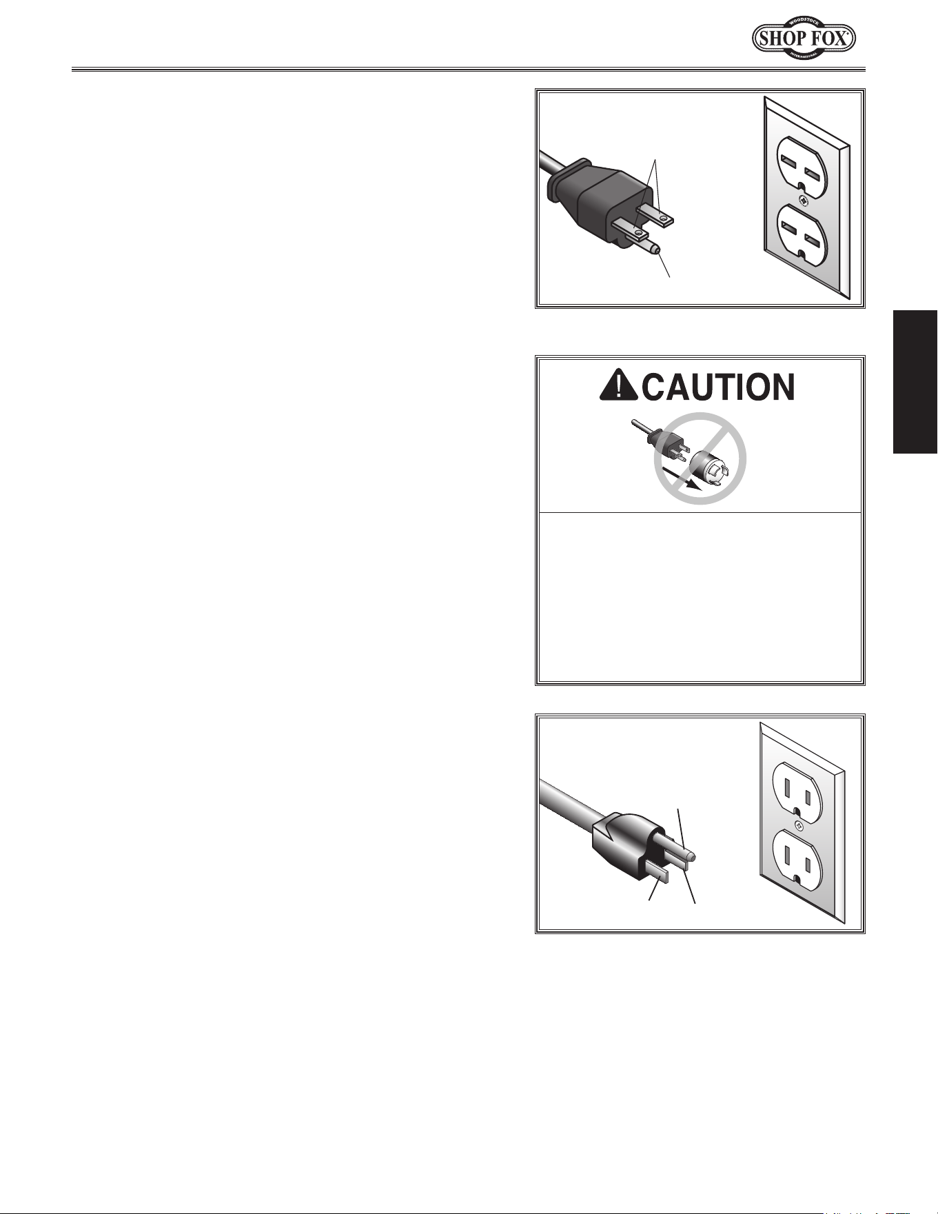
Grounding Prong
Current Carrying Prongs
6-15 PLUG
GROUNDED
6-15 RECEPTACLE
220V
Figure.1. NEMA 6-15 plug & receptacle.
Grounding Prong
Neutral Hot
5-15 PLUG
GROUNDED
5-15 RECEPTACLE
110V
Figure.2. NEMA 5-15 plug & receptacle.
Extension.Cords
We do not recommend using an extension cord with
this machine. Extension cords cause voltage drop, which
may damage electrical components and shorten motor
life. Voltage drop increases with longer extension cords
and smaller gauge sizes (higher gauge numbers indicate
smaller sizes).
Any extension cord used with this machine must contain a
ground wire
, match the required
plug and receptacle, and
meet the following requirements:
Minimum.Gauge.Size.................................. 12.AWG
Maximum.Length.(Shorter.is.Better).................50.ft.
For.W1666.220V.Connection
For.W1685.110V.Connection
A NEMA 5-15 plug has a grounding prong that must be
attached to the equipment-grounding wire inside the
included power cord. The plug must only be inserted
into a matching receptacle (see Figure.2) that is properly
installed and grounded in accordance with all local codes.
A NEMA 6-15 plug has a grounding prong that must be
attached to the equipment-grounding wire inside the
included power cord. The plug must only be inserted
into a matching receptacle (see Figure.1) that is properly
installed and grounded in accordance with all local codes.
No. adapter. should. be. used. with. the.
required. plug..If. the.plug.does. not.fit.
the.available.receptacle.or.the.machine.
must. be. reconnect ed. to. a. different.
type.of.circuit,.the.reconnection.must.
be.made.by.an.electr ician.or.qualified.
service. p ersonnel. and. it. must. comply.
with.all.local.codes. and.ordinances.
-12-
Model W1666/W1685 (For Machines Mfd. Since 2/15)
SETUP
Keep. machine. disconnected. from.
power.until.instructed.otherwise.
This machine has been carefully packaged for safe
transportation. If you notice the machine has been
damaged during shipping, please contact your authorized
Shop Fox dealer immediately.
Unpacking
SET UP
The following is a description of the main components
shipped with the Model W1666/W1685. Lay the
components out to inventory them.
Note: If you can't find an item on this list, check the
mounting location on the machine or examine the
packaging materials carefully. Occasionally we pre-install
certain components for safer shipping.
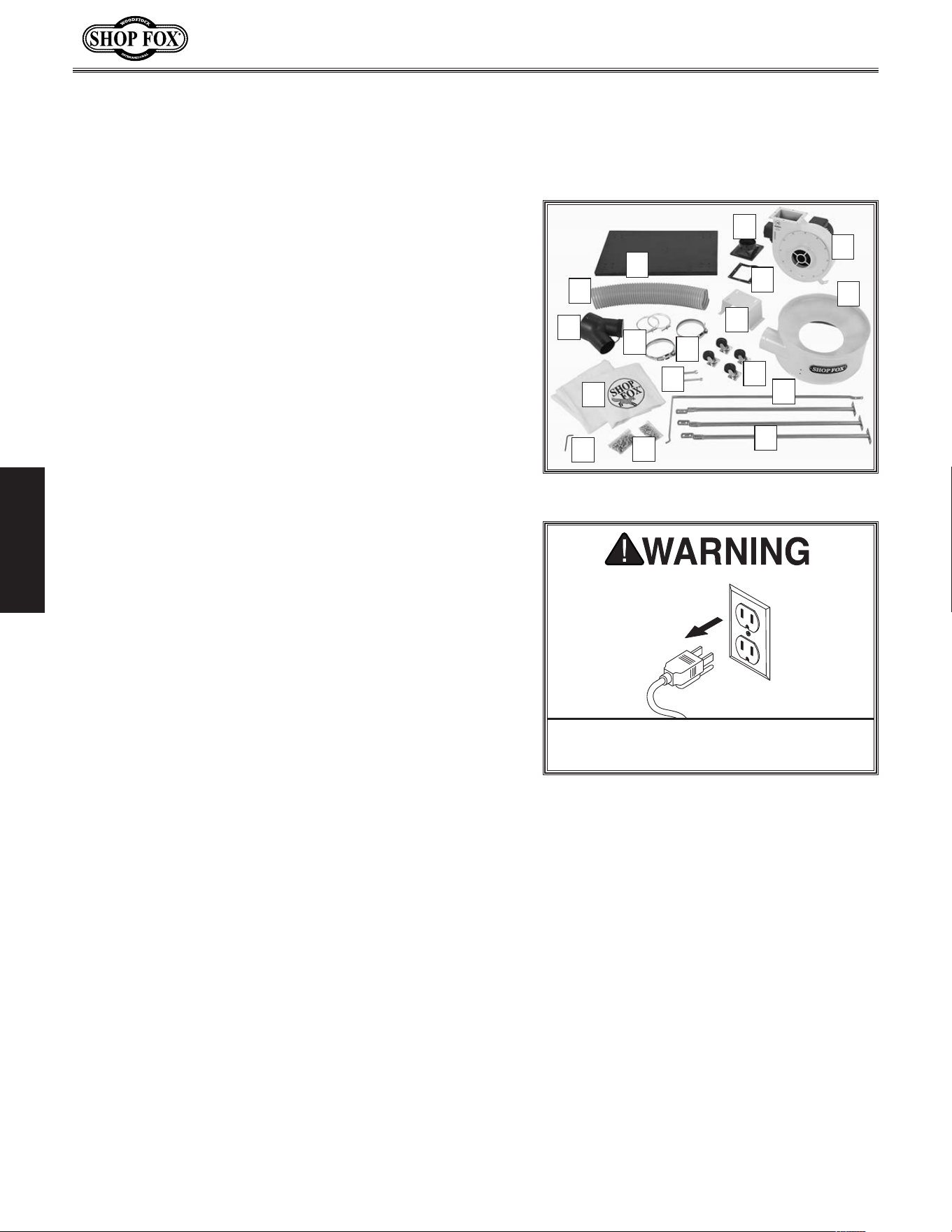
Shipping.Inventory.(Figure.3):. Qty
A. Base Plate ..................................................1
B.. Outlet Flange 5" ...........................................1
C. Outlet Gasket ..............................................1
D.. Impeller/Motor Assembly .................................1
E.. Separator ...................................................1
F. Motor Mount ................................................1
G. Transfer Hose 5" ...........................................1
H.. Inlet Y-Connector 6" x (2) 4" .............................1
I. Hose Clamps 5" ............................................2
J. Bag Clamps .................................................2
K.. Swivel Casters ..............................................4
L.. Wrenches, 8/10mm & 11/13mm Open Ends ... 1 Each
M.. Bags, Upper & Lower .............................. 1 Each
N. Separator Supports ........................................3
O.. Upper Bag Hanger .........................................1
P. Hex Wrench 5mm ..........................................1
Q. Hardware Bags for W1666
— Hex Bolts M8-1.25 x 16 ............................... 26
— Hex Bolts M8-1.25 x 25 .................................4
— Flat Washers 8mm..................................... 34
— Hex Nuts M8-1.25 .......................................4
— Phillips Head Screws M6-1 x 10 ..................... 16
— Flat Washers 6mm..................................... 16
— Hex Nuts M6-1 ......................................... 16
Inventory
Figure.3. Shipping inventory.
B
C
D
A
O
N
Q
P
L
K
J
I
M
F
G
H
E
Q. Hardware Bags for W1685
— Hex Bolts M8-1.25 x 16 ............. 18
— Hex Bolts M8-1.25 x 25 .............. 4
— Flat Washers 8mm................... 26
— Hex Nuts M8-1.25 .................... 4
— Phillips Head Screws M6-1 x 10 ... 16
—Hex Bolts M6-1 x 20 .................. 6
— Flat Washers 6mm................... 22
— Hex Nuts M6-1 ....................... 22
-13-
Model W1666/W1685 (For Machines Mfd. Since 2/15)
SETUP
Assembly
Select an assembly area that is free from clutter and well
lighted.
Tools.Needed. Qty
Phillips Screwdriver #2 .........................................1
Wrench or Socket 10mm .......................................1
Wrench or Socket 13mm .......................................2
To.assemble.the.dust.collector,.do.these.steps:
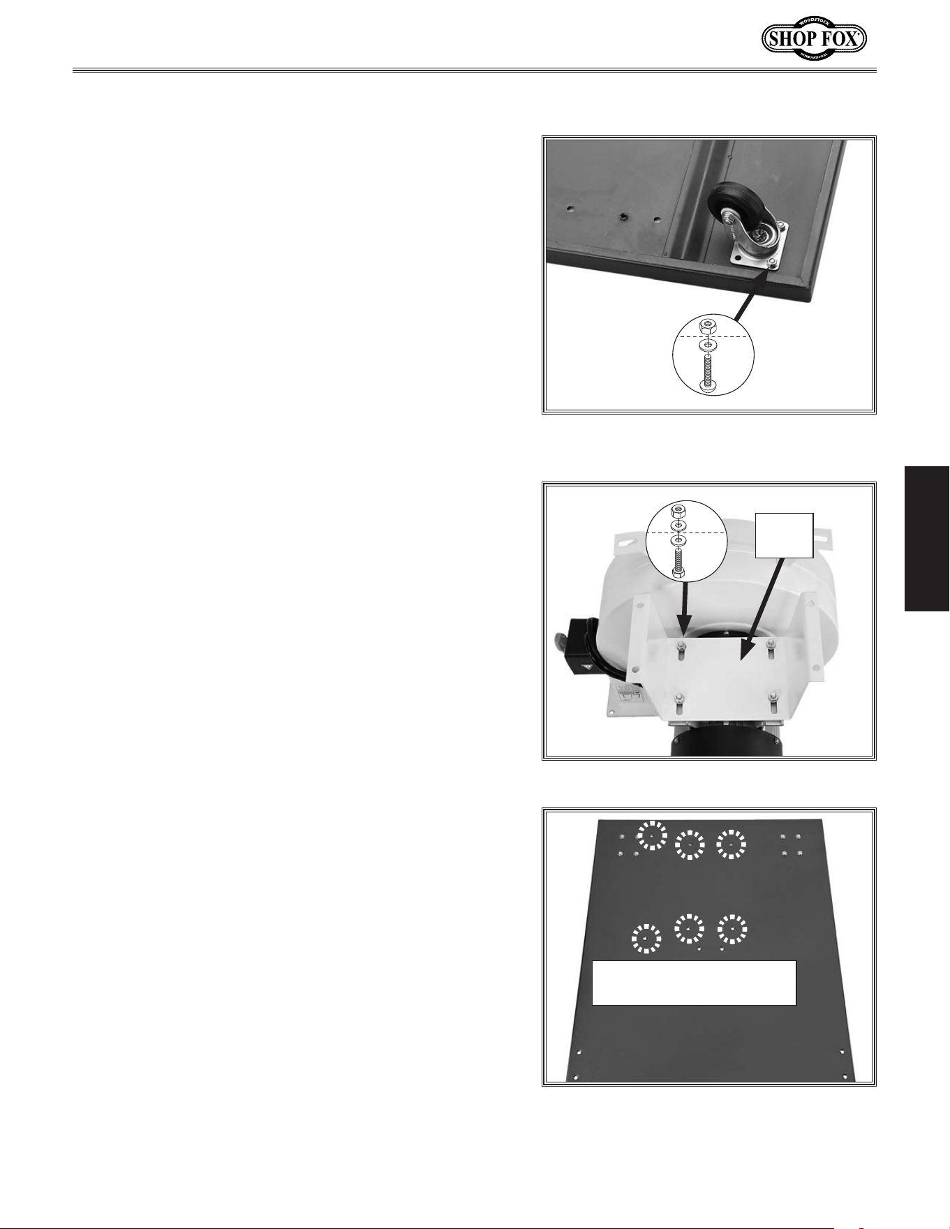
1. Install four swivel casters to base plate with (16)
M6-1 x 10 Phillips head screws, (16) 6mm flat
washers, and (16) M6-1 hex nuts, as shown in
Figure.4.
Figure.4. Swivel caster attached to base
plate.
x 16
2. With assistance from another person, turn impeller/
motor assembly upside down and attach motor
mount as shown in Figure.5, with (4) M8-1.25 x 25
hex bolts, (8) 8mm flat washers, and (4) M8-1.25 hex
nuts.
Note:.Finger tighten these fasteners for now so that
mount can be adjusted in a later step.
3. With assistance from another person, turn impeller/
motor assembly right side up and position it over
attachment holes on base plate (see Figure.6).
Figure.6. Location of impeller/motor
assembly attachment holes.
Impeller/Motor Assembly
Attachment Holes
Figure.5. Motor mount attached to motor.
x 4
Motor
Mount
-14-
Model W1666/W1685 (For Machines Mfd. Since 2/15)
SETUP
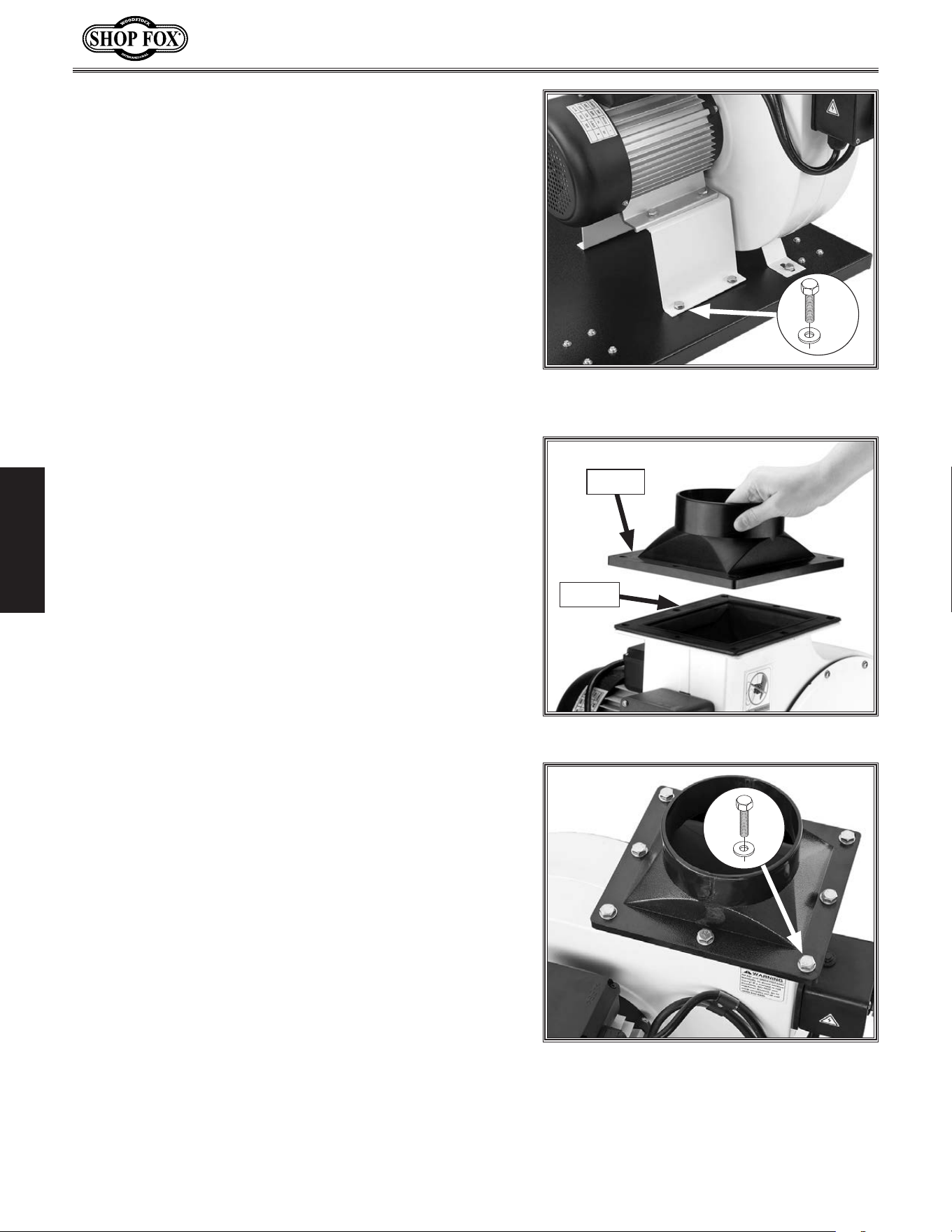
4.. Attach impeller/motor assembly to base plate with
(6) M8-1.25 x 16 hex bolts and (6) 8mm flat washers
(see Figure.7).
Note:.Adjust the position of motor mount to
align holes, then fully tighten fasteners installed
in Step 2 that secure mount to impeller/motor
assembly.
Figure.8. Outlet gasket and flange.
Gasket
Flange
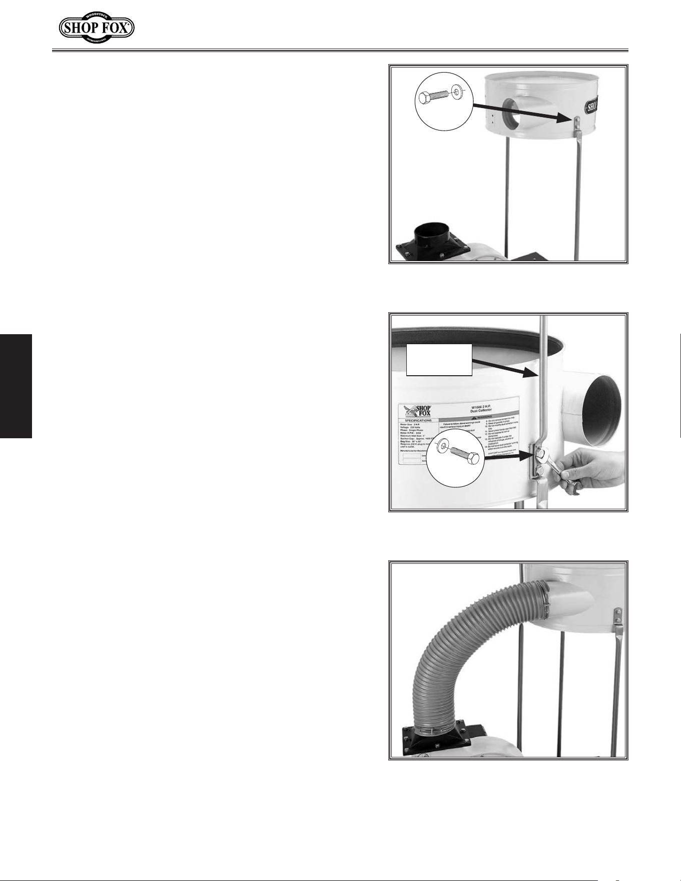
5. Place outlet gasket on top of outlet port, as shown
in Figure.8.
Figure.9. Outlet flange attached.
6. Model.W1666: Place outlet flange on top of gasket
and secure it with (8) M8-1.25 x 16 hex bolts and (8)
8mm flat washers (see Figure.9).
Model.W1685: Place outlet flange on top of gasket
and secure it with (6) M6-1 x 20 hex bolts, (6) 6mm
flat washers, and (6) M6-1 hex nuts.
Figure.7. Impeller/motor assembly
attached to base plate.
x 6
-15-
Model W1666/W1685 (For Machines Mfd. Since 2/15)
SETUP
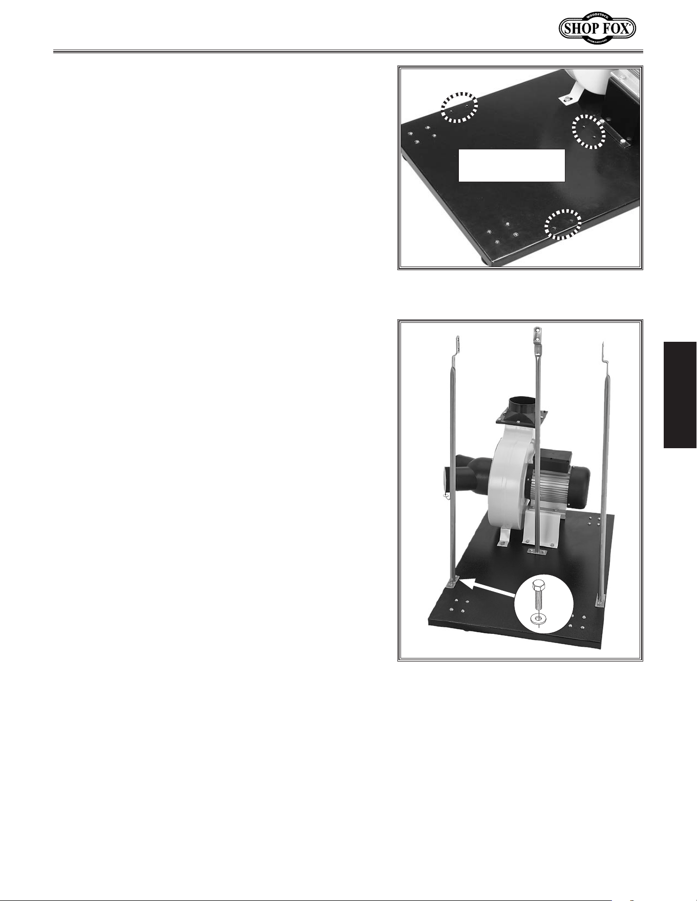
Figure.10. Locations of separator support
attachment holes in base plate.
Separator Support
Attachment Holes
7. Position each of the three separator supports over
the base plate attachment holes shown in Figure.10,
with top bend facing inward, then secure them with
(6) M8-1.25 x 16 hex bolts and (6) 8mm flat washers
(see Figure.11).
Figure.11. Separator supports attached to
base plate.
x 6
-16-
Model W1666/W1685 (For Machines Mfd. Since 2/15)
SETUP
8. With assistance from another person, attach
separator to the front and rear supports, as shown
in Figure.12, with (4) M8-1.25 x 16 hex bolts and (4)
8mm flat washers.
Note:.Do not attach separator to side support until
next step.
9. Attach side separator support and upper bag hanger
to separator with (2) M8-1.25 x 16 hex bolts and (2)
8mm flat washers, as shown in Figure.13.
x 4
Figure.13. Side support and upper bag
hanger attached to separator.
x 2
Upper Bag
Hanger
Figure.14. Transfer hose attached.
10. Slide a hose clamp over each end of transfer hose,
then slide hose ends over impeller outlet flange port
and separator inlet port (see Figure.14).
Note:.Slide ends as far as possible over each port to
ensure a tight fit.
11. Tighten hose clamps to secure transfer hose.
Figure.12. Separator attached to front and
rear supports.
x 4
-17-
Model W1666/W1685 (For Machines Mfd. Since 2/15)
SETUP
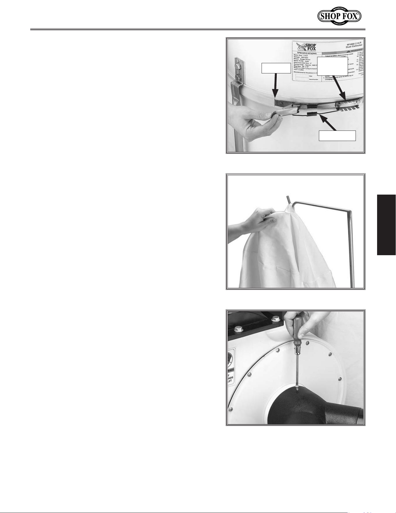
12. Insert toothed-end of each bag clamp into opening of
bag rim, then slide it completely around rim cavity
to meet other end (see Figure.15).
Figure.15. Securing bag to separator.
Opening
Bag Clamp
Toothed
End
Figure.16. Hanging upper bag.
. Note:.The upper bag has the SHOP FOX
®
logo on it
and the lower bag is plain.
13. Hang upper bag, as shown in Figure.16, and attach
bag rim to the separator in the manner shown in
Figure.15.
14. Attach lower bag to separator in a similar manner.
Figure.17. Attaching inlet Y-connector.
15. Attach inlet Y-connector to impeller cover with pre-
installed Phillips head screw, as shown in Figure.17.
-18-
Model W1666/W1685 (For Machines Mfd. Since 2/15)
SETUP
Once the assembly is complete, test run your machine
to make sure it runs properly and is ready for regular
operation.
The test run consists of verifying the following: 1) The
motor powers up and runs correctly, and 2) the safety
disabling mechanism on the switch works correctly.
If, during the test run, you cannot easily locate the source
of an unusual noise or vibration, stop using the machine
immediately, then review Troubleshooting on Page.34.
If you still cannot remedy a problem, contact our Tech
Support at (360) 734-3482 for assistance.
To.test.run.the.machine,.do.these.steps:
1. Make sure you understand the safety instructions
at the beginning of the manual, and verify that the
machine is setup properly.
2. Ensure all tools and objects used during setup are
cleared away from the machine.
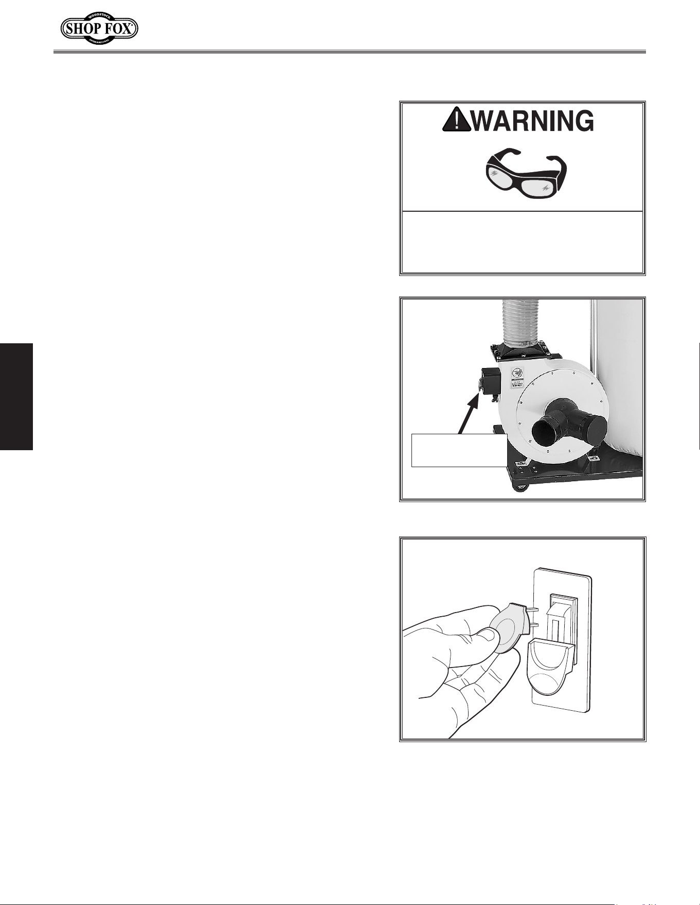
3. Make sure the paddle ON/OFF switch (see Figure.18)
is pushed down—this ensures the machine will not
unexpectedly start when connected to power.
4. Connect the machine to the power source.
5. Verify that the machine is operating correctly by
lifting the paddle ON/OFF switch up and turning the
machine ON. The machine should run smoothly with
little or no vibration or rubbing noises.
— Investigate and correct strange or unusual noises
or vibrations before operating the machine further.
Always disconnect the machine from power when
investigating or correcting potential problems.
6. Turn the machine OFF.
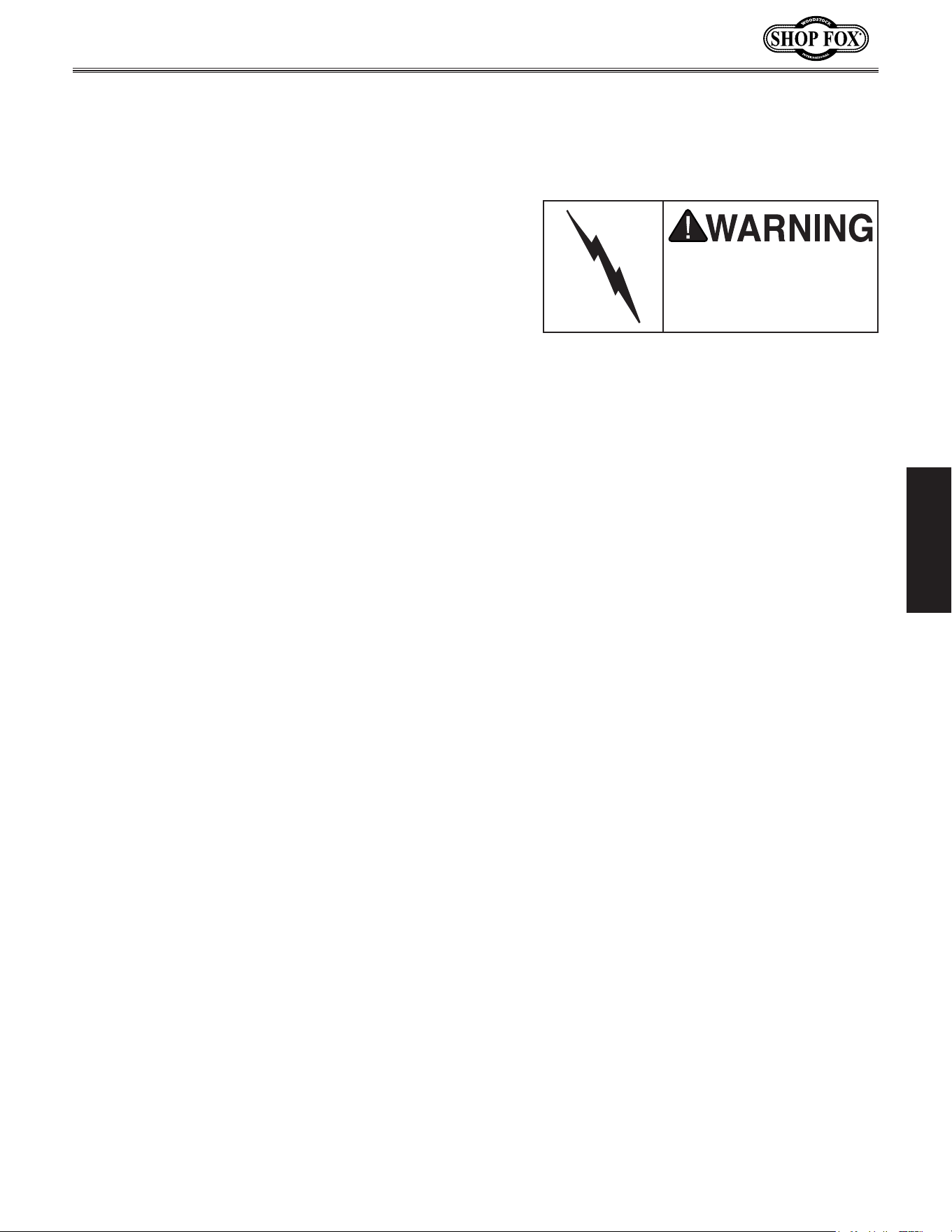
7. Remove the switch disabling key, as shown in
Figure.19).
8. Try to start the machine with the paddle switch—the
machine should not start.
— If the machine starts, immediately stop the
machine. The switch disabling feature is not
working correctly. Call Tech Support for help.
Test.Run
Figure.19. Removing switch key from
paddle switch.
Projectiles. thrown. from. the. machine.
could. cause. serious. eye. injury.. Wear.
safety. glasses. to. reduce. the. risk. of.
injury.
Figure.18. Paddle ON/OFF switch location.
Paddle ON/OFF
Switch
-19-
Model W1666/W1685 (For Machines Mfd. Since 2/15)
SETUP
DESIGNING.THE.SYSTEM
General
This dust collector can be operated as either a stationary,
central dust collector or a mobile unit. There are
advantages and disadvantages to both setups. The
advantage of the mobile system is eliminating the cost of
many ducts and fittings. On the other hand, the stationary
system is more efficient and customizable.
If using this dust collector as a stationary system, put
the dust collector in an out-of-the way location such as
a corner or separate room. The dust collector is capable
of collecting dust from up to two machines running
simultaneously. Woodstock offers a complete line of dust
collection accessories for setting up a stationary, central
dust collector system. Additionally, Woodstock offers
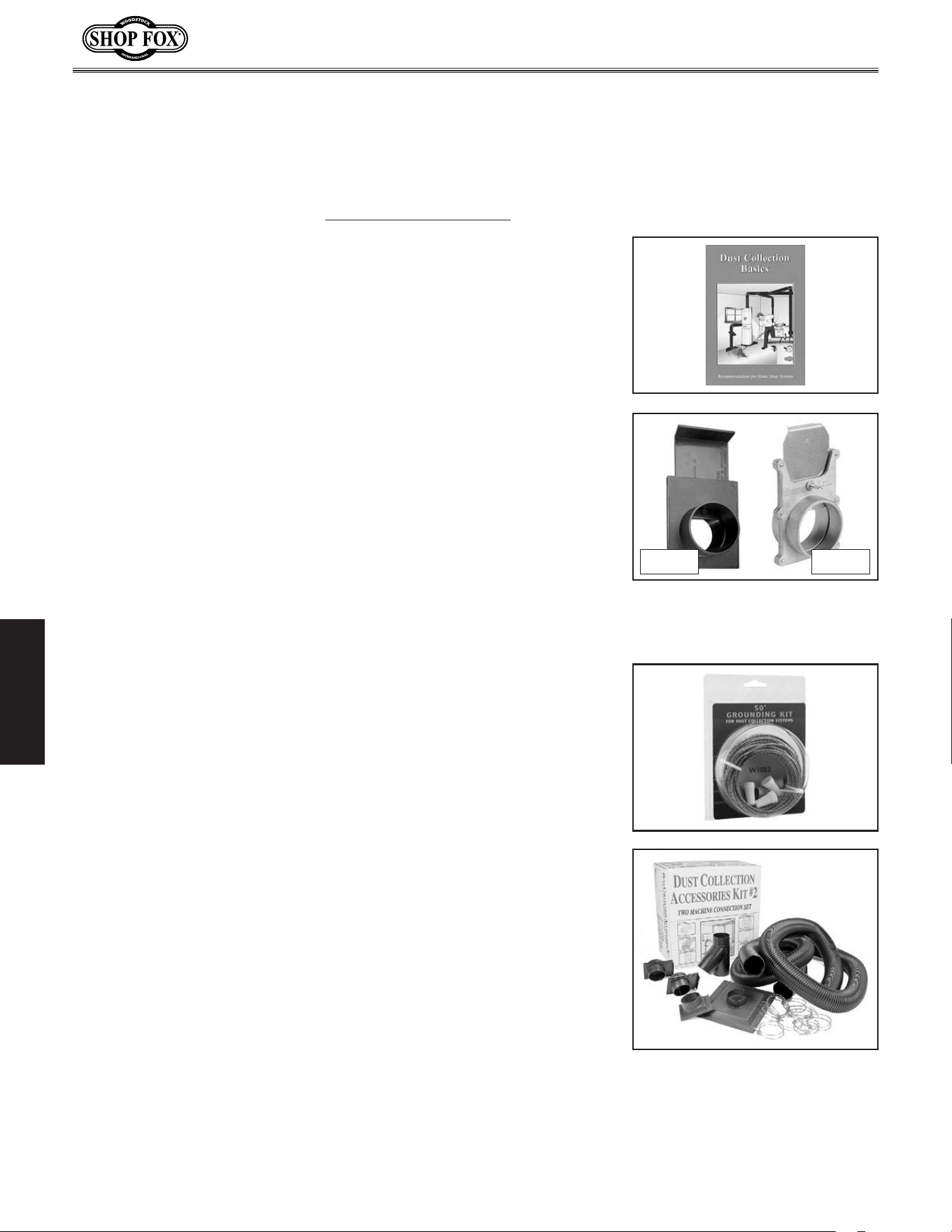
a complete guide book entitled Dust.Collection.Basics.
(refer to Page.30 for additional details).
Whatever system you choose, always make sure there
are no open flames or pilot lights in the same room as
the dust collector. There is a risk of explosion if dust is
dispersed into the air.
Always guard against
static electric build-up
by grounding all dust
collection lines.
Duct.Material
You have many choices regarding main line and branch
line duct material. For best results, use metal duct for
the main line and branch lines, then use short lengths
of flexible hose to connect each machine to the branch
lines.
Plastic duct is also a popular material for home shops.
However, be aware that there is a fire or explosion hazard
if plastic duct material is used for dust collection without
being grounded against static electrical charge build-up.
This topic will be discussed later in this section. Another
problem with using plastic is that it is less efficient per
foot than metal.
-20-
Model W1666/W1685 (For Machines Mfd. Since 2/15)
SETUP
Plastic duct generates
static electrical build-up
that can cause fire or
shock. Properly ground
all plastic duct to
reduce this risk.
Plastic.Duct
The popularity of plastic duct is due to the fact that it
is an economical and readily available product. It is also
simple to assemble and easily sealed against air loss. The
primary disadvantage of plastic duct for dust collection is
the inherent danger of static electrical build-up.
Metal.Duct
Advantages of metal duct is its conductivity, efficiency,
and that it does not contribute to static electrical charge
build-up. However, static charges are still produced when
dust particles strike other dust particles as they move
through the duct. Since metal duct is a conductor, it can
be grounded quite easily to dissipate any static electrical
charges.
There are a number of options when it comes to metal
duct, but metal duct that is specially manufactured
for dust collection is the best choice. When selecting
your metal duct, choose high quality metal duct with
smooth welded internal seams that will minimize airflow
resistance. This type of duct usually connects to other
ducts or elbows with a simple, self-sealing clamp, is very
quick and easy to assemble, and can be readily dismantled
and re-installed. This is especially important if you ever
need to change things around in your shop or add more
tools.
Avoid inferior metal duct that requires you to cut it to
length and snap it together. This type of duct is time
consuming to install because it requires you to seal all
the seams with silicone and screw the components on
the ends with sheet metal screws. Another disadvantage
is the rough internal seams and crimped ends that
unavoidably increase static pressure loss.
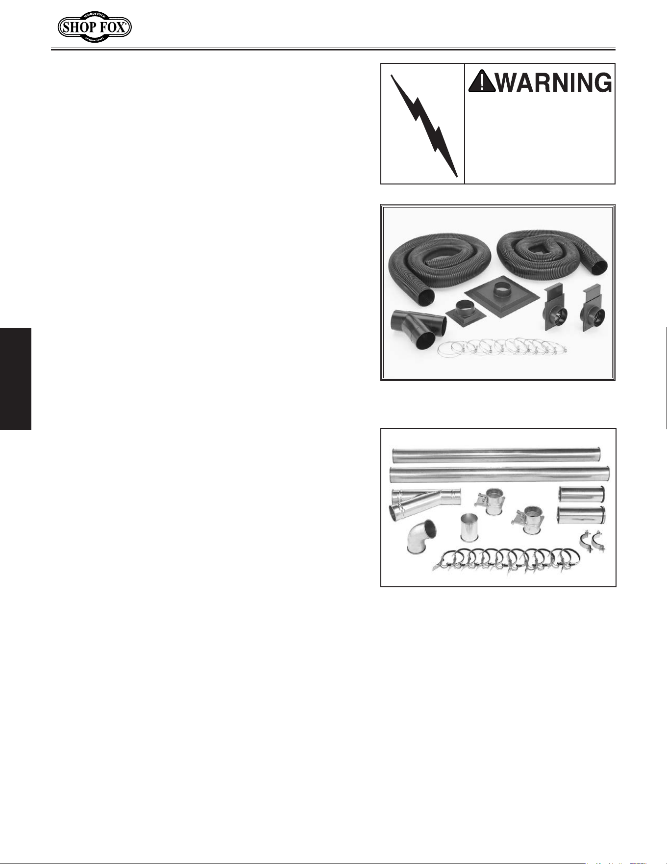
Figure.20. Examples of plastic duct
components (Model W1055).
Figure.21. Examples of metal duct
components.
-21-
Model W1666/W1685 (For Machines Mfd. Since 2/15)
SETUP
Flexible.Duct
Flexible hose is generally used for short runs, small shops
and at rigid duct-to-tool connections. There are many
different types of flex hose on the market today. These
are manufactured from materials such as polyethylene,
PVC, cloth hose dipped in rubber and even metal,
including steel and aluminum.
The superior choice here is metal flex hose that is
designed to be flexible, yet be as smooth as possible to
reduce static pressure loss.
There are also many kinds of pure plastic flexible hose,
such as non-perforated drainage type hose and dryer vent
hose. Drainage type hose, while being economical, does
not quite have the flexibility required for dust collection.
The inside of the duct is also deeply corrugated and
can increase the static pressure loss by as much as 50%
over smooth wall duct. Dryer vent hose, while being
completely flexible, is non-resistant to abrasion and has
a tendency to collapse in a negative pressure system. We
DO NOT recommend using dryer vent hose in your dust
collection system.
If using flex-hose, you should choose one of the many
types that are designed specifically for the movement of
solid particles, i.e. dust, grains, and plastics. However, the
cost of specifically designed flexible duct can vary greatly.
Woodstock offers polyethylene hose, which is well suited
for the removal of particulate matter, especially sawdust,
since it is durable and completely flexible. Polyethylene
is also very economical and available in a wide variety of
diameters and lengths for most applications.
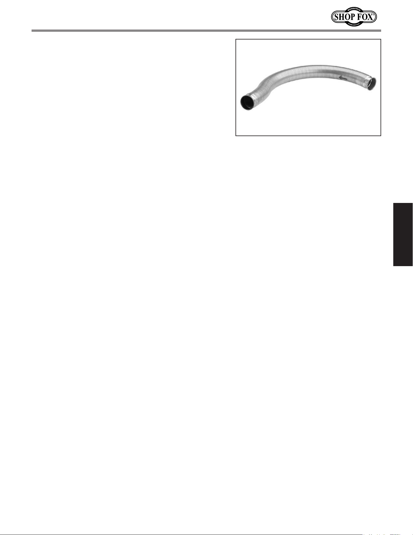
Figure.22. Example of flexible metal duct.
-22-
Model W1666/W1685 (For Machines Mfd. Since 2/15)
SETUP
System.Grounding
Since plastic hose is abundant, relatively inexpensive,
easily assembled and air tight, it is a very popular
material for conveying dust from woodworking machines
to the dust collector. We recommend using flexible hose
(flex-hose) to connect the woodworking machine to the
dust collector. However, plastic flex-hose and plastic duct
are an insulator, and dust particles moving against the
walls of the plastic duct create a static electrical build
up. This charge will build until it discharges to a ground.
If a grounding medium is not available to prevent static
electrical build up, the electrical charge will arc to the
nearest grounded source. This electrical discharge may
cause an explosion and subsequent fire inside the system.
To protect against static electrical build up inside a non-
conducting duct, a bare copper wire should be placed
inside the duct along its length and grounded to the dust
collector. You must also confirm that the dust collector
is continuously grounded through the electrical circuit to
the electric service panel.
If you connect the dust collector to more than one
machine by way of a non-conducting branching duct
system and blast gates, the system must still be grounded
as mentioned above. We recommend inserting a
continuous bare copper ground wire inside the entire duct
system (see Figure.23).and attaching the wire to each
grounded woodworking machine and dust collector.
Be sure that you extend the bare copper wire down all
branches of the system. Do not forget to connect the
wires to each other with wire nuts when two branches
meet at a “Y” or “T” connection.
Ensure that the entire system is grounded. If using plastic
blast gates to direct air flow, the grounding wire must be
jumped (see Figure.24) around the blast gate without
interruption to the grounding system.
We also recommend wrapping the outside of all plastic
ducts with bare copper wire to ground the outside of the
system against static electrical build up. Wire connections
at Y’s and T’s should be made with wire nuts.
Attach the bare ground wire to each stationary
woodworking machine and attach to the dust collector
frame with a ground screw, as shown in Figure.23.
Ensure that each machine is continuously grounded to the
grounding terminal in your electric service panel.
Plastic
Blast
Gate
Copper
Ground
Wire
Metal
Duct
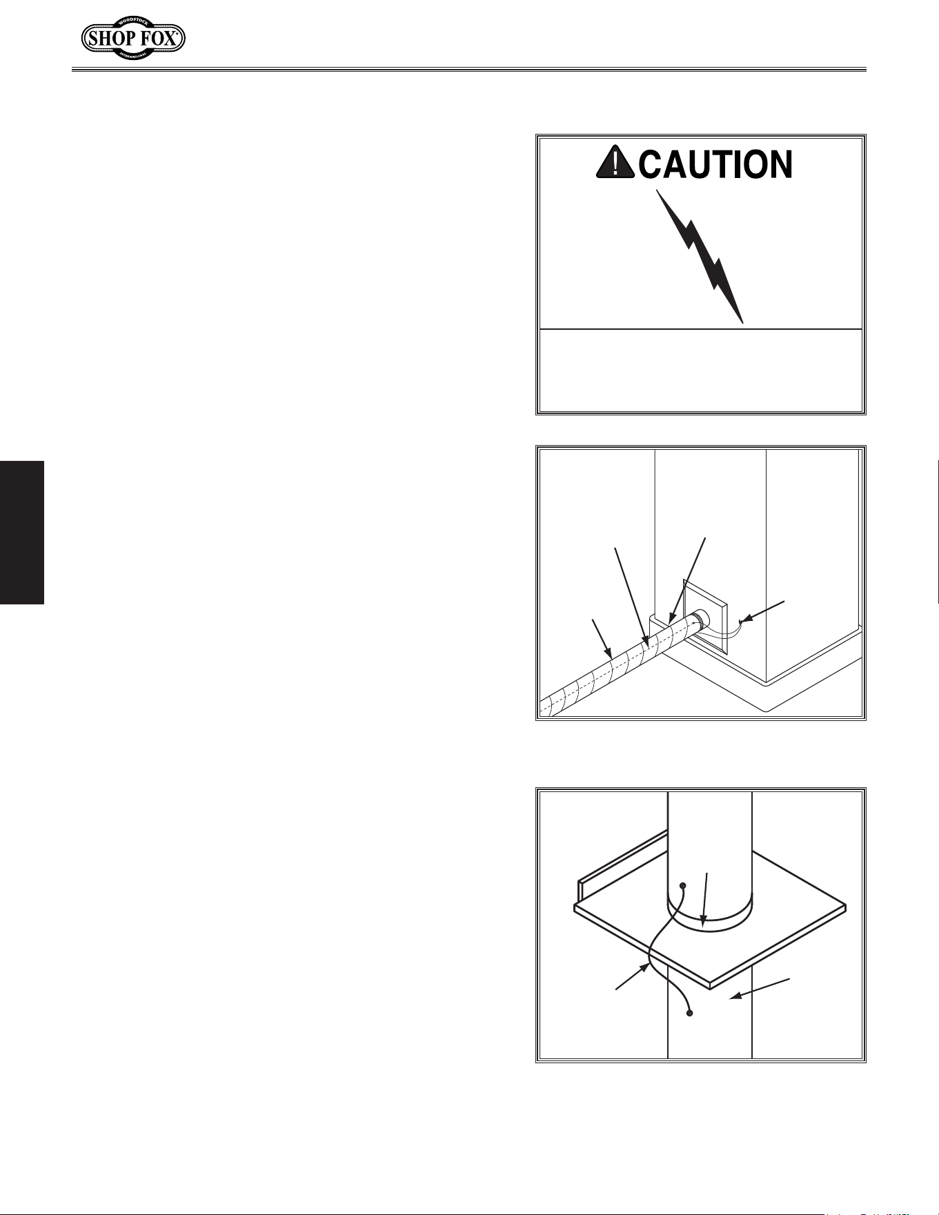
Figure.24. Ground jumper wire when using
plastic blast gates and metal duct.
External
Ground
Wire
Internal
Ground
Wire
Flex-Hose
Ground
Screw
Figure 23. Flex-hose grounded to
machine.
Always.guard.against.static.electrical.
build.up.by.grounding.all.dust.
collect ion.lines .
-23-
Model W1666/W1685 (For Machines Mfd. Since 2/15)
SETUP
System.Design
Decide.Who.Will.Design
For most small-to-medium sized shops, you can design and
build the dust collection system yourself without hiring
engineers or consultants. We have included some basic
information here to get you started on a basic design.
If you have a large shop or plan to design a complicated
system, we recommend doing additional research beyond
this manual or seeking the help of an expert.
Sketch.Your.Shop.Layout
When designing a successful dust collection system,
planning is the most important step. In this step, sketch a
basic layout of your shop, including space requirements of
different machines.
Your sketch only needs the basic details of the shop
layout, similar to Figure.25, including all your current/
planned machines and your planned placement of the
dust collector.
Sketch.a.Duct.Layout
For the next step, sketch how you will connect your
machines to the dust collector. Consider these general
guidelines for an efficient system:
1. Machines that produce the most saw dust should be
placed nearest to the dust collector (i.e. planers and
sanders).
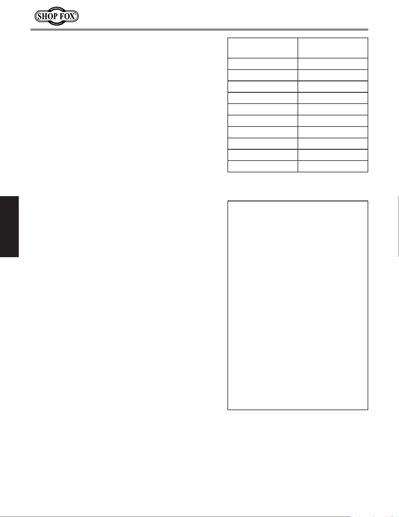
2. Ideally, you should design the duct system to have
the shortest possible main line and secondary branch
ducts. See Figures.26–27.for ideas of efficient versus
inefficient duct layouts.
Dust
Collector
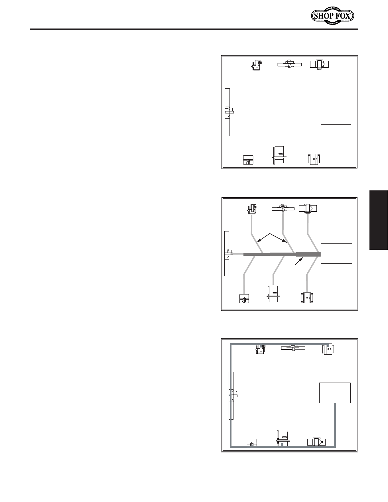
Figure.25. Example sketch of basic shop
layout.
Main
Line Duct
Branch
Line
Ducts
GOOD
Dust
Collector
Figure.26. Example sketch of an efficient
duct layout.
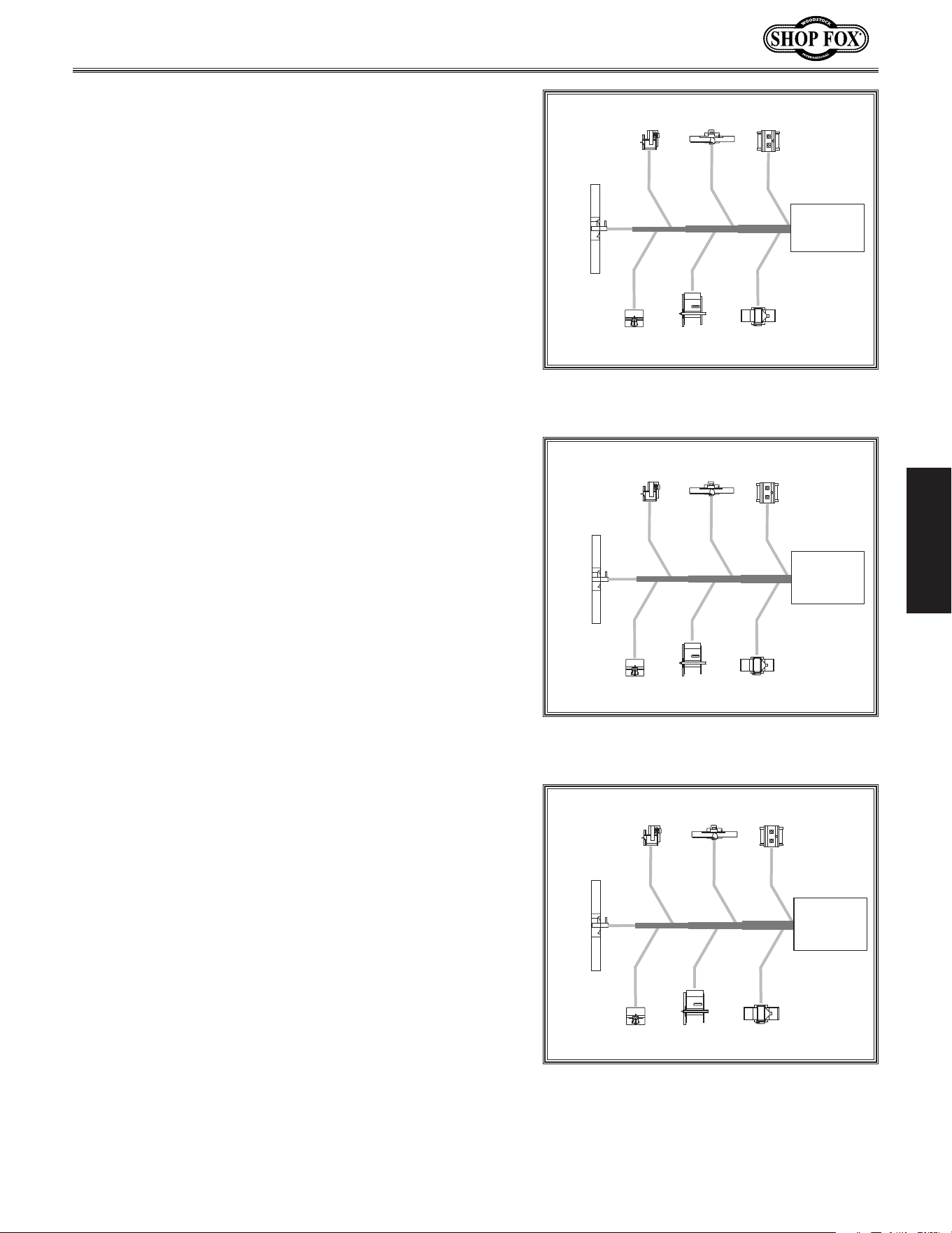
BAD
Dust
Collector
Figure.27. Example sketch of an
inefficient duct layout.
-24-
Model W1666/W1685 (For Machines Mfd. Since 2/15)
SETUP
3. Directional changes should be kept to a minimum.
The more directional change fittings you use directly
increases the overall resistance to airflow.
4. Gradual directional changes are more efficient than
sudden directional changes (i.e. use the largest
corner radius possible when changing hose or pipe
direction).
5. Each individual branch line should have a blast gate
immediately after the branch to control suction from
one machine to another.
6. The simpler the system, the more efficient and less
costly it will be.
Determine.Required.CFMs
Since each machine produces a different amount of
sawdust, the requirements for the minimum amount of
CFM to move that sawdust is unique to the machine (for
example, a planer produces more sawdust than a table
saw). Knowing this required CFM is important to gauging
which size of duct to use.
Refer to Figure.28 for a close estimation of the airflow
each machine requires. Keep in mind that machines that
generate the most sawdust should be placed closest to
the dust collector. If the machine has multiple dust ports,
the total CFM required is the sum of all ports.
If the machine does not have a built-in dust port, use the
table in Figure.29.to determine which size of dust port to
install.
Machine .
Dust.Port.Size
Approximate.
Required.CFM
2" 98
2.5" 150
3" 220
4" 395
5" 614
6" 884
7" 1203
8" 1570
9" 1990
10" 2456
Figure 28. Approximate required airflow
for machines, based on dust port size.
Machine. Average.Dust.Port.Size
Table Saw .................................. 4"
Miter/Radial-Arm Saw .................... 2"
Jointer (6" and smaller) ................. 4"
Jointer (8"-12") ............................ 5"
Thickness Planer (13" and smaller) .... 4"
Thickness Planer (14"-20") ............... 6"
Shaper ...................................... 4"
Router (mounted to table) .............. 2"
Bandsaw .................................... 4"
Lathe ........................................ 4"
Disc Sander (12" and smaller) ........... 2"
Disc Sander (13-18") ...................... 4"
Belt Sander (6" and smaller) ............ 2"
Belt Sander (7"-9") ........................ 3"
Edge Sander (6" x 80" and smaller) .... 4"
Edge Sander (6" x 80" and larger) ...... 5"
Drum Sander (24" and smaller) ..... 2 x 4"
Drum Sander (24" and larger) ....... 4 x 4"
Widebelt Sander (18" and smaller) ..... 5"
Widebelt Sander (24"-37" single head)
..................................... 2 x 6"
Widebelt Sander (24"-51" double head)
..................................... 5 x 4"
Figure 29. Dust port size and quantity per
average machine.
-25-
Model W1666/W1685 (For Machines Mfd. Since 2/15)
SETUP
Write the required CFM for each machine on your sketch,
as shown in Figure.30.
Determining.Main.Line.Duct.Size
The general rule of thumb for a main line duct is that the
velocity of the airflow must not fall below 3500 FPM.
For small/medium sized shops, using the inlet size of the
dust collector as the main line duct size will usually keep
the air velocity above 3500 FPM and, depending on your
system, will allow you to keep multiple branches open at
one time.
Mark your drawing, as shown in Figure.31, but using the
inlet size for your dust collector as the main line.
Determining.Branch.Line.Duct.Size
The general rule of thumb for a branch line duct is that
the velocity of the airflow must not fall below 4000 FPM.
For small/medium sized shops, using the dust port size
from the machine as the branch line duct size will achieve
the correct velocity in most applications. However, if the
dust port on the machine is smaller than 4", make the
branch line 4" and neck the line down right before the
dust port.
Note: Systems with powerful dust collectors work better
if multiple blast gates are left open. This also allows you
to run two machines at once. Experiment with different
combinations of blast gates open/closed to find the best
results for your system.
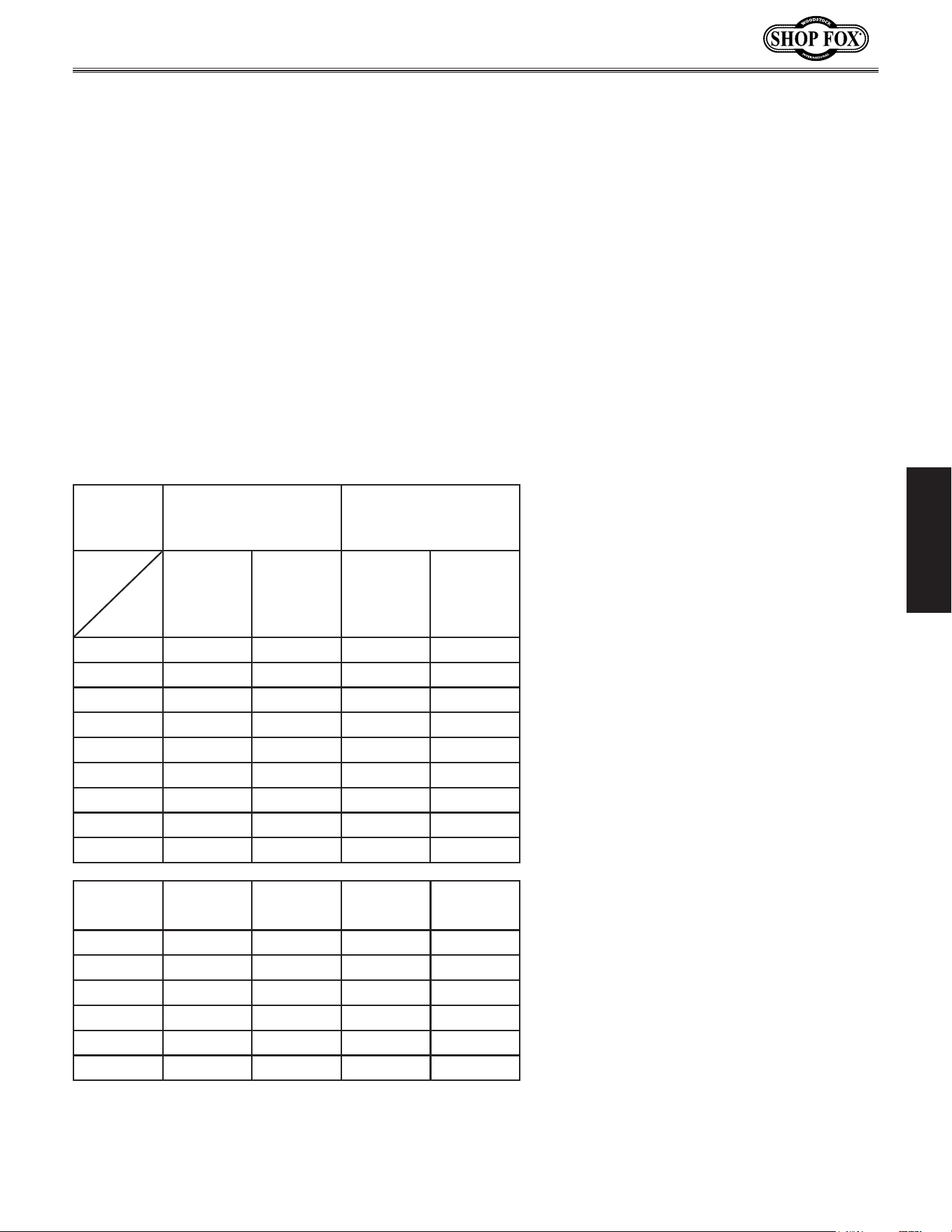
Write your determined branch line sizes on your drawing,
as shown in Figure.32.
395
395
614
790395
220
98
Table Saw
Planer/
Moulder
Miter
Saw
Jointer
Sander
PlanerShaper
Dust
Collector
Figure 30. CFM requirements labeled for
each machine.
395
395
614
790395
220
98
5" 6" 7"
Table Saw
Planer/
Moulder
Miter
Saw
Jointer Sander
PlanerShaper
Dust
Collector
Figure 31. Main line size labeled on
sketch.
395
395
614
790
395
220
98
4"
4"
4" 6"
4" 4" 5"
5" 6" 7"
Table Saw
Miter
Saw
Jointer Sander
PlanerShaper
Planer/
Moulder
Dust
Collector
Figure 32. Branch line duct sizes labeled.

-26-
Model W1666/W1685 (For Machines Mfd. Since 2/15)
SETUP
If two machines will connect to the same branch line and
both will operate at the same time, then add the required
CFM for each machine together and find the closest total
CFM in the table in Figure.33.to determine the correct
branch size.
If both machines will never run at the same time,
reference the machine with the biggest dust port in the
table below and add blast gates after the Y-branch to
open/close the line to each machine.
Planning.Drop.Downs
Plan the drop downs for each machine, using blast gates
wherever possible to control airflow (see Figure.34).
Total.CFM Branch.Line.Size
400 4"
500 4"
600 5"
700 5"
800 6"
900 6"
1000 6"
Figure 33. Sizing chart for multiple
machines on the same branch line.
To Machine
Blast Gate
Flex Pipe
Rigid Pipe
Rigid Pipe
(Main Line)
Elbow
Clamp
Y Branch
Figure.34. Example of drop down setup.
-27-
Model W1666/W1685 (For Machines Mfd. Since 2/15)
SETUP
Calculating.Duct.Resistance
Adding duct work, elbows, branches and any other
components to a duct line increases airflow resistance
(static pressure loss). This resistance can be minimized by
using rigid (smooth) pipe and gradual curves, as opposed
to flexible pipe and 90˚ elbows.
To help you think about this resistance, imagine riding a
bicycle in a tunnel that is an exact replica of your duct
work. If the inside of the tunnel is very bumpy (flexible
pipe) and has a lot of sharp turns (90˚ elbows), it will take
a lot more effort to travel from one end to the other.
The purpose of calculating the resistance is to determine
if it is low enough from the machine to the dust collector
to meet the given CFM requirement for the machine. Use
the following tables to calculate the resistance of duct
work.
Duct.Dia . Approximate.Static.
Pressure.Loss .Per.
Foot.of.Rigid.Pipe
Approximate.Static.
Pressure.Loss .Per.
Foot. of.Flex.Pipe
Main.
Lines.at.
3500.FPM
Branch.
Lines.
at.4000.
FPM
Main.
Lines.at.
3500.FPM
Branch.
Lines.
at.4000.
FPM
2" 0.091 0.12 2 0.35 0.453
2.5" 0.08 0.107 0.306 0.397
3" 0.071 0.094 0.271 0.352
4" 0.057 0.075 0.215 0.28
5" 0.046 0.059 0.17 2 0.225
6" 0.037 0.047 0.13 6 0.18
7" 0.029 0.036 0.10 6 0.141
8" 0.023 0.027 0.08 0.10 8
9" 0.017 0.019 0.057 0.079
Fitting.
Dia.
90˚.
Elbow
45˚.
Elbow
45˚. .
Wye(Y)
90˚.
Wye(Y)
3" 0.47 0.235 0.282 0.18 8
4" 0.45 0.225 0.375 0.225
5" 0.531 0.266 0.354 0.236
6" 0.564 0.282 0.329 0.235
7" 0.468 0.234 0.324 0.216
8" 0.405 0.203 0.297 0.18 9

-28-
Model W1666/W1685 (For Machines Mfd. Since 2/15)
SETUP
In most small/medium shops it is only necessary to
calculate the line with the longest duct length or the
most fittings (operating under the assumption that if the
line with the highest resistance works, the others will be
fine).
To.calculate.the.static.pressure.of.any.given.line.in.the.
system,.follow.these.steps:
1. Make a list of each size duct in the line, including
the length, and multiply those numbers by the static
pressure value given in the previous table.
2. List each type of elbow or branch and multiply the
quantity (if more than one) by the static pressure
loss given in the previous table.
3. Add the additional factors from the table in
Figure.35.to your list.
4. Total your list (see Figure.36 for an example) to
come up with your overall static pressure loss
number for that line.
Note: Always account for a seasoned filter, so you
don't end up with a system that only works right
when the filter is clean.
. Additionally, when calculating static pressure loss
to determine if multiple lines can be left open at
the same time, only include the main line numbers
once.
5. Compare the total static pressure loss for that line
to the maximum static pressure loss found on the
data sheet for your machine (located toward the
front of this manual).
—If the CFM for your static pressure loss is above the
requirement of the machine, then the line will
most likely be successful. Congratulations! You’ve
just designed your own dust system. Compile a list
of materials and refer to Accessories beginning
on Page.30,.to start buying the components
necessary to make your system a reality.
Additional.Factors
Static.
Pressure
Seasoned (well used) Dust
Collection Filter
1"
Entry Loss at Large
Machine Hood
2"
Figure.35. Additional factors affecting
static pressure.
Main Line
6" Rigid Pipe (.037) at 20' ........ 0.740
Branch Line
4" Rigid Pipe (.075) at 10' ........ 0.750
4" Flex Pipe (.28) at 5' ........ 1.400
Elbows/Branches
6" 45˚ Y-Branch ................ 0.329
4" 45˚ Elbow ........................ 0.225
Additional Factors
Seasoned Filter ................ 1.000
Total Static Pressure Loss 4.444
Figure 36. Totaling static pressure
numbers.
—If the CFM for your static pressure
loss is below the requirement of
the machine, then that line will
not effectively collect the dust.
You must then modify some of the
factors in that line to reduce the
static pressure loss. Some of the
ways to do this include 1) installing
larger duct, 2) reducing amount of
flexible duct used, 3) increasing
machine dust port size, 4) moving
machine closer to dust collector
to eliminate duct length, and 5)
reducing 90˚ elbows or replacing
them with 45˚ elbows.
-29-
Model W1666/W1685 (For Machines Mfd. Since 2/15)
OPERATIONS
OPERATIONS
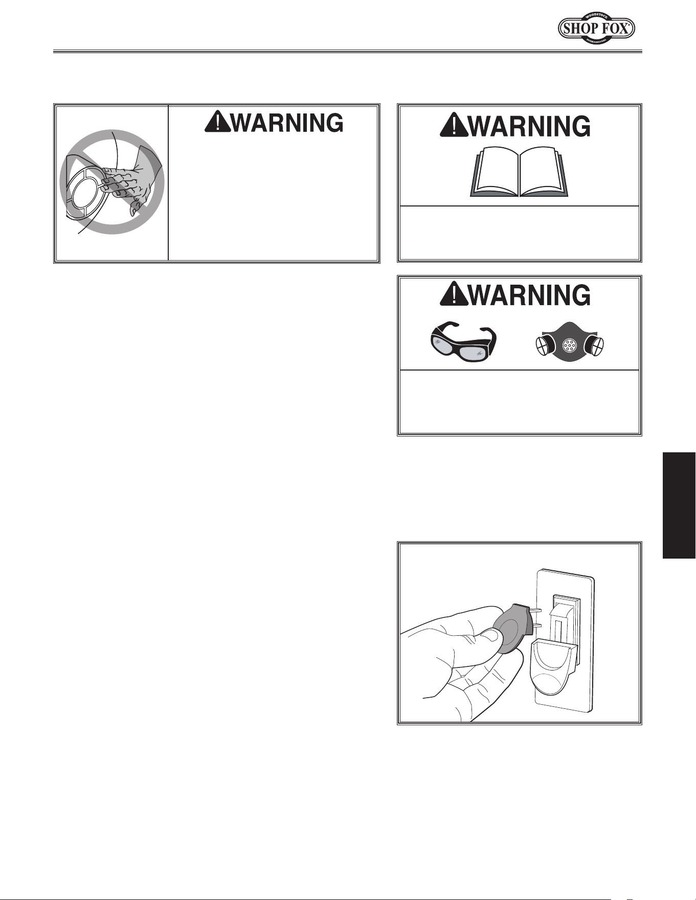
Do. NOT. put. hands. or. small.
objects. near. inlet. openings.
during.operation..Objects.sucked.
into. the. inlet. will. meet. with.
the. impeller. blade.. Failure. to.
heed. this. warning. could. result.
in. property. damage. or. personal.
injury.
General
Operating a dust collector is simple and straightforward.
Turn the dust collector ON, then turn the dust producing
machine ON. When you are finished with the machine
operation, turn the machine OFF, then turn the dust
collector OFF.
Blast gates can be used at the start of each branch line to
control the air flow from the woodworking machine to the
dust collector. If a machine is not being used, keep the
blast gate closed to maintain higher levels of efficiency
throughout the system.
Machine.Storage
When the dust collector is not in use, unplug the power
cord from the power source. Place the cord away from
potential damage sources, such as high traffic areas,
sharp objects, heat sources, harsh chemicals, water, damp
areas, etc.
Disabling.Switch
The paddle ON/OFF switch can be disabled by removing
the key, as shown in Figure.37. Disabling the switch in
this manner can prevent unauthorized operation of the
machine, which is important if it is not kept inside an
access-restricted building or in a location where children
may be present.
IMPORTANT:.Disabling the switch only restricts its
function. It is not a substitute for disconnecting
machine from power when adjusting or servicing.
Figure.37. Disabling switch by removing
key.
To. reduce. your. risk. of. serious. injury.
or. damage. to. the. machine,. read. this.
entire.manual.BEFORE.using.machine.
To. reduce. the. risk. of. eye. injury. and.
long-term. respiratory. damage,. always.
wear. safety. glasses. and. a. respirator.
while.operating.this.machine.
-30-
Model W1666/W1685 (For Machines Mfd. Since 2/15)
OPERATIONS
ACCESSORIES
The following dust collector accessories may be available through your local Woodstock International
Inc. Dealer. If you do not have a dealer in your area, these products are also available through online
dealers. Please call or e-mail Woodstock International Inc. Customer Service to get a current listing of
dealers at: 1-800-840-8420 or at sales@woodstockint.com.
The Model.W1053.Grounding.Kit provides everything you need to
ground a dust collection system, including directions for installation.
A large system may need more than one kit, so keep plenty of these
on hand. This safety accessory is essential to any complete dust
collection assortment.
Blast.Gates are available in both black ABS plastic and aluminum.
Plastic blast gates are economically priced, have a textured surface
and an easy sliding gate action. For those customers who prefer
metal, our top quality aluminum blast gates feature a cast aluminum
body with steel gate and locking knob. The following types and mod-
els are available:
The Model.W1055.Dust.Collection.Accessories.Kit.#2 provides
the necessary hoses, clamps, hoods and fittings to connect two
woodworking machines to a dust collector. Air flow to each
machine is controlled by a blast gate. The kit comes complete with
comprehensive instructions and can be expanded even further using
our other dust collection accessories (list enclosed in each box).
Kit.includes:
• (2) 4" Blast gates (W1007)
• (2) 4" x 10' Hose (W1031)
• (1) Table saw dust hood (W1004)
• (1) Universal dust hood (W1010)
• (1) 4" Y-fitting (W1015)
• (10) 4" Wire hose clamps (W1317)
• Shipping weight: 15 lbs. 14 oz.
• Package size: 24" x 24" x 12"
Black.ABS.Plastic.Blast.Gates
W1006 3" Outer Diameter
W1007 4" Outer Diameter
W1008 5" Outer Diameter
W1009 6" Outer Diameter
Aluminum.Blast.Gates
W1141 3" Outer Diameter
W1142 4" Outer Diameter
W1141W1006
The Model.W1050.Dust.Collection.Basics.Handbook skillfully
guides you through all the necessary steps to desing and construct
an efficient dust collection system, including a bunch of tips for
easy installation. With sixty pages of consice information, including
photographs and illustrations, this handbook is a “must.”
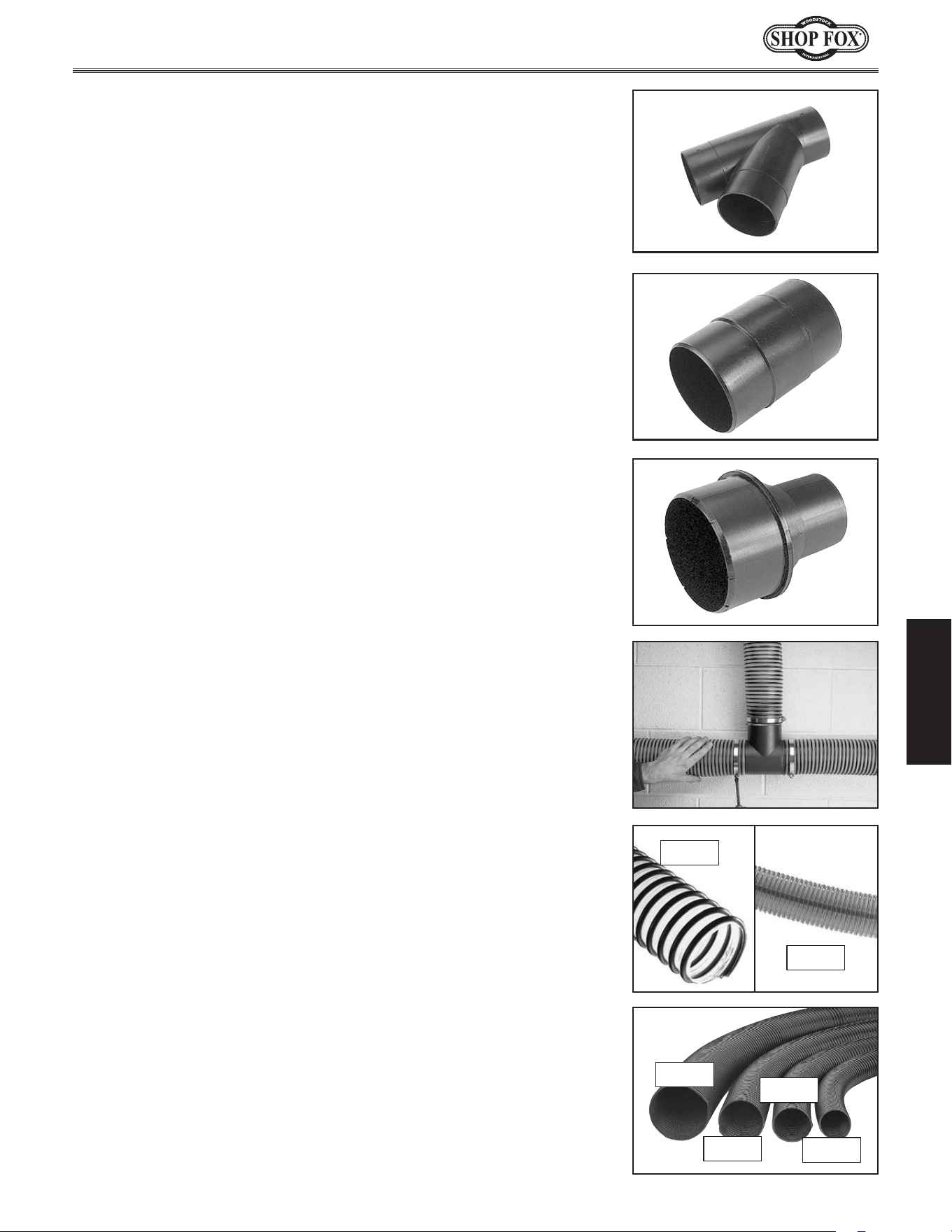
-31-
Model W1666/W1685 (For Machines Mfd. Since 2/15)
OPERATIONS
Y-Fittings.are used to attach branch lines to service more than
one machine. This design provides increased lateral air flow and
efficiency over other types of fittings.
W1014: 3" Outer Diameter
W1015: 4" Outer Diameter
Splices.are used to connect full sections of hose for longer runs or to
utilize short sections.
W1018: 3" Outer Diameter
W1019: 4" Outer Diameter
Reducers provide a step down from a larger main line to smaller
branch lines. This step-down increases air velocity near the machine
where it's needed most. These three size reductions will handle most
system needs.
W1020: 3" x 2" Outer Diameter
W1011: 4" x 3" Outer Diameter
W1037: 5" x 4" Outer Diameter
T-fittings provide the option of adding branches to a system to service
each machine in a shop. T's are very helpful when space or design
constraints prohibit the use of Y's.
W1012: 3" Outer Diameter
W1013: 4" Outer Diameter.
Woodstock International hoses are ideally suited for dust removal
because of their strength, durability, and flexibility. Available in the
most requested sizes and priced to move! The following types and
models are available:
Wire-Reinforced.
Clear.Hose.
W1034 4" x 10'
W1035 5" x 10'
W1036 6" x 10'
D3887 7" x 3'
D3888 7" x 10'
D3889 8" x 3'
D3890 8" x 10'
D3891 9" x 2'
D3892 9" x 10'
Clear.Dust.
Collection.Hose
D4202 2" x 10'
D4203 2
1
⁄2" x 10'
D4204 3" x 10'
D4205 3" x 20'
D4206 4" x 10'
D4207 4" x 20'
D4198 4" x 50'
D4208 5" x 10'
Black.Dust.
Collection.Hose
D4211 2" x 10'
D4212 2
1
⁄2" x 10'
D4213 3" x 10'
D4214 3" x 20'
D4215 3" x 50'
D4216 4" x 10'
D4217 4" x 20'
D4218 5" x 10'
D4202
W1035
D4218
D4214
D4216
D4211
-32-
Model W1666/W1685 (For Machines Mfd. Since 2/15)
MA INTENANCE
MAINTENANCE
Regular periodic maintenance on your machine will
ensure its optimum performance. Make a habit of
inspecting your machine each time you use it.
Check.for.the.following.conditions.and.repair.or.
replace.when.necessary:
• Loose mounting bolts.
• Worn switch.
• Worn or damaged cords and plugs.
• Almost full collection bag.
• Any other condition that could hamper the safe
operation of this machine.
General
Lubrication
Since all bearings are shielded and permanently
lubricated, simply leave them alone until they need to be
replaced. Do not lubricate them.
Always empty the collection bags on a regular basis.
Emptying the collection bags allows the machine to
operate at a much higher level of efficiency.
Always wear the appropriate respirator or dust mask and
safety glasses when emptying the collection bags. Small
dust particles can escape the bags during emptying,
causing them to become airborne and easily inhaled.
This microscopic airborne dust is extremely unhealthy to
breathe and can cause serious health problems.
While the Model W1666/W1685 excels at collecting the
majority of wood dust produced by your machines, it
is not an air filter; therefore, we strongly recommend
the supplemental aid of a shop air filter such as the
Woodstock Model W1690. Air filters are designed to
collect the smaller dust particles in the air that escape
from the dust collector bag.
Bag.Cleaning
To. reduce. risk. of. shock. or. accidental.
startup,. always. disconnect. machine.
from. power. before. adjustments,.
maintenance,.or.ser vice.
Always wear a respirator and safety
glasses when emptying dust collection
bags on the dust collector. Sawdust
may cause allergic reactions or
respiratory problems.
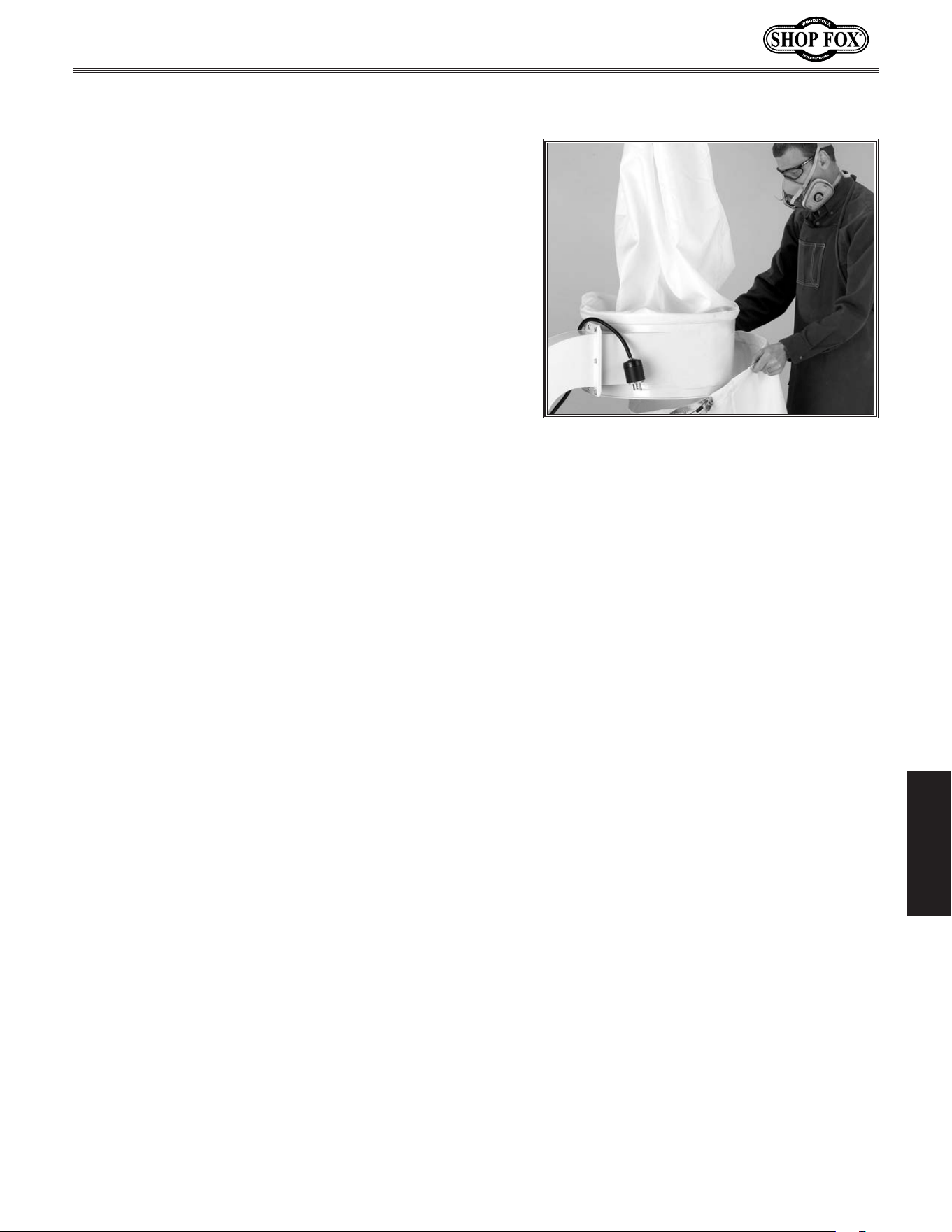
-33-
Model W1666/W1685 (For Machines Mfd. Since 2/15)
MA INTENANCE
The lower bags should be emptied when they become
2
⁄3
to
3
⁄4 full.
To.empty.the.dust.collection.bags,.do.these.steps:
1.. DISCONNECT MACHINE FROM POWER!
2.. Make sure you are wearing safety glasses and a
respirator.
3.. Release the quick release clamp securing each
collection bag, then remove the bags from the
collector, as shown in Figure.38.
4. Place a garbage bag over each bag, invert the bag,
and shake the dust out.
5. Dispose of the dust and re-install the bags with the
clamps.
Replacing.Bags
Figure.38. Replacing lower bag.
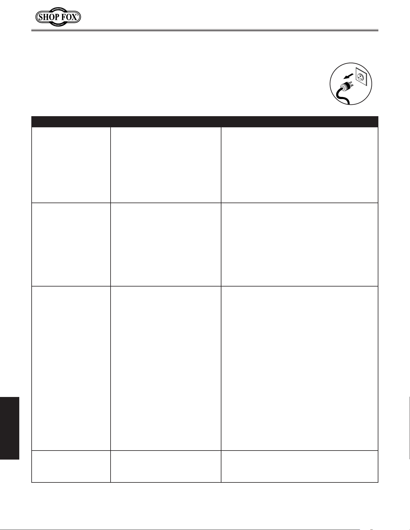
-34-
Model W1666/W1685 (For Machines Mfd. Since 2/15)
SERVICE
SERVICE
Troubleshooting
This section covers the most common problems and corrections with this type of
machine. WARNING!.DO.N OT.make.any.adjustments.until.power.is.disconnected.and.
moving.parts.have.come.to.a.complete.stop!
PROBLEM POSSIBLE.CAUSE CORRECTIVE.ACTION
Machine does not start or
a breaker trips.
1. Switch disabling key removed.
2. Power supply switched OFF or is at
fault.
3. Wall fuse/circuit breaker is blown/
tripped.
4. Wiring is open/has high resistance.
5. Motor ON button or ON/OFF switch
is at fault.
6. Motor is at fault.
1. Install switch disabling key.
2. Ensure power supply is switched on; ensure power
supply has the correct voltage.
3. Ensure circuit size is suitable for this
machine; replace weak breaker.
4. Check for broken wires or disconnected/corroded
connections, and repair/replace as necessary.
5. Replace faulty ON button or ON/OFF switch.
6. Test/repair/replace.
Machine has vibration or
noisy operation.
1. Motor, motor mount, or other
mounting component is loose or
broken.
2. Motor fan is rubbing on fan cover.
3. Impeller is loose or damaged and
unbalanced.
4. Motor bearings are at fault.
1. Retighten. Use thread locking fluid if necessary.
Replace stripped fasteners or damaged components
if necessary.
2. Replace dented fan cover; replace loose/damaged
fan.
3. Disconnect dust collector from power, and inspect
the impeller for dents, bends, loose fins. Replace
the motor and impeller as a set if the motor shaft
and the impeller hub are damaged.
4. Test by rotating shaft; rotational grinding/loose
shaft requires bearing replacement.
Dust collector does not
adequately collect dust or
chips; poor performance.
1. Dust collection bag is full.
2. Restriction in duct line.
3. Dust collector is too far away, or
there are too many sharp bends in
the ducting.
4. Lumber is wet and dust not
flowing through ducting smoothly.
5. Leaks in ducting or too many open
ports.
6. Not enough open branch lines,
causing a velocity drop in the main
line.
7. Ducting or machine dust ports are
incorrectly sized.
8. The machine dust collection
design is inadequate.
9. The dust collector is too small
for the dust collection system,
or ducting layout design is
inadequate.
1. Empty collection bag.
2. Remove restriction in the duct line. A plumbing
snake may be necessary.
3. Relocate the dust collector closer to the point of
suction, and rework ducting without sharp bends.
Refer to System Design, beginning on Page 23.
4. Process lumber with less than 20% moisture
content.
5. Rework the ducting to eliminate all leaks. Close
dust ports for lines not being used.
6. Open 1 or 2 more blast gates to different branch
lines to allow the velocity in the main line to
increase.
7. Re-install correctly sized ducts and fittings. Refer
to System Design beginning on Page 23 for more
solutions.
8. Use a dust collection nozzle on a stand.
9. Install a larger dust collector to power your dust
collection system.
Sawdust being blown into
the air from the dust
colle c tor.
1. Duct clamps or dust collection
bag are not properly clamped and
secured.
2. Bag clamp is loose or damaged.
1. Resecure ducts and dust collection bag, making
sure duct and bag clamps are tight and completely
over the ducts and bags.
2. Retighten bag clamp.
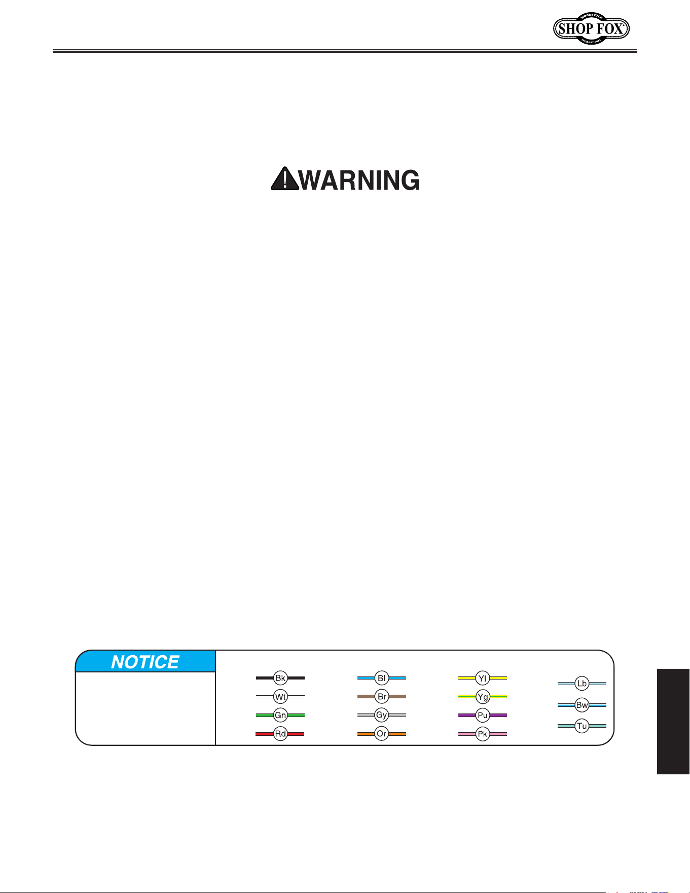
-35-
Model W1666/W1685 (For Machines Mfd. Since 2/15)
SERVICE
These pages are current at the time of printing. However, in the spirit of improvement, we may
make changes to the electrical systems of future machines. Study this diagram carefully. If you notice
differences between your machine and these wiring diagrams, call Woodstock International Technical
Support at (360) 734-3482.
SHOCK HAZARD.
Working on wiring that is
connected to a power source is extremely
dangerous. Touching electrified parts will
result in personal injury including but not
limited to severe burns, electrocution,
or death. Disconnect the power from
the machine before servicing electrical
components!
QUALIFIED ELECTRICIAN
. Due to the inherent
hazards of electricity, only a qualified
electrician should perform wiring tasks on this
machine. If you are not a qualified electrician,
get help from one before attempting any kind
of wiring job.
WIRE CONNECTIONS.
All connections must be
tight to prevent wires from loosening during
machine operation. Double-check all wires
disconnected or connected during any wiring
task to ensure tight connections.
WIRE/COMPONENT DAMAGE
. Damaged wires
or components increase the risk of serious
personal injury, fire, or machine damage.
If you notice that any wires or components
are damaged while performing a wiring task,
replace those wires or components before
completing the task.
MOTOR WIRING
. The motor wiring shown in these
diagrams is current at the time of printing,
but it may not match your machine. Always
use the wiring diagram inside the motor
junction box.
MODIFICATIONS. Using aftermarket parts or
modifying the wiring beyond what is shown
in the diagram may lead to unpredictable
results, including serious injury or fire.
CAPACITORS/INVERTERS. Some capacitors and
power inverters store an electrical charge for
up to five minutes after being disconnected
from the power source. To avoid being
shocked, wait at least this long before working
on these components.
ELECTRICAL REQUIREMENTS. You MUST follow
the electrical requirements at the beginning
of this manual when connecting your machine
to a power source.
EXPERIENCING DIFFICULTIES. If you are
experiencing difficulties understanding the
information included in this section, contact
our Technical Support at (360) 734-3482.
Electrical.Safety.Instructions
The photos and diagrams
included in this section are
best viewed in color. You
can view these pages in
color at www.shopfox.biz.
BLACK
WHITE
GREEN
RED
BLUE
BROWN
GRAY
ORANGE
YELLOW
YELLOW
GREEN
PURPLE
PINK
LIGHT
BLUE
BLUE
WHITE
TUR-
QUOISE
WIRING DIAGRAM COLOR KEY
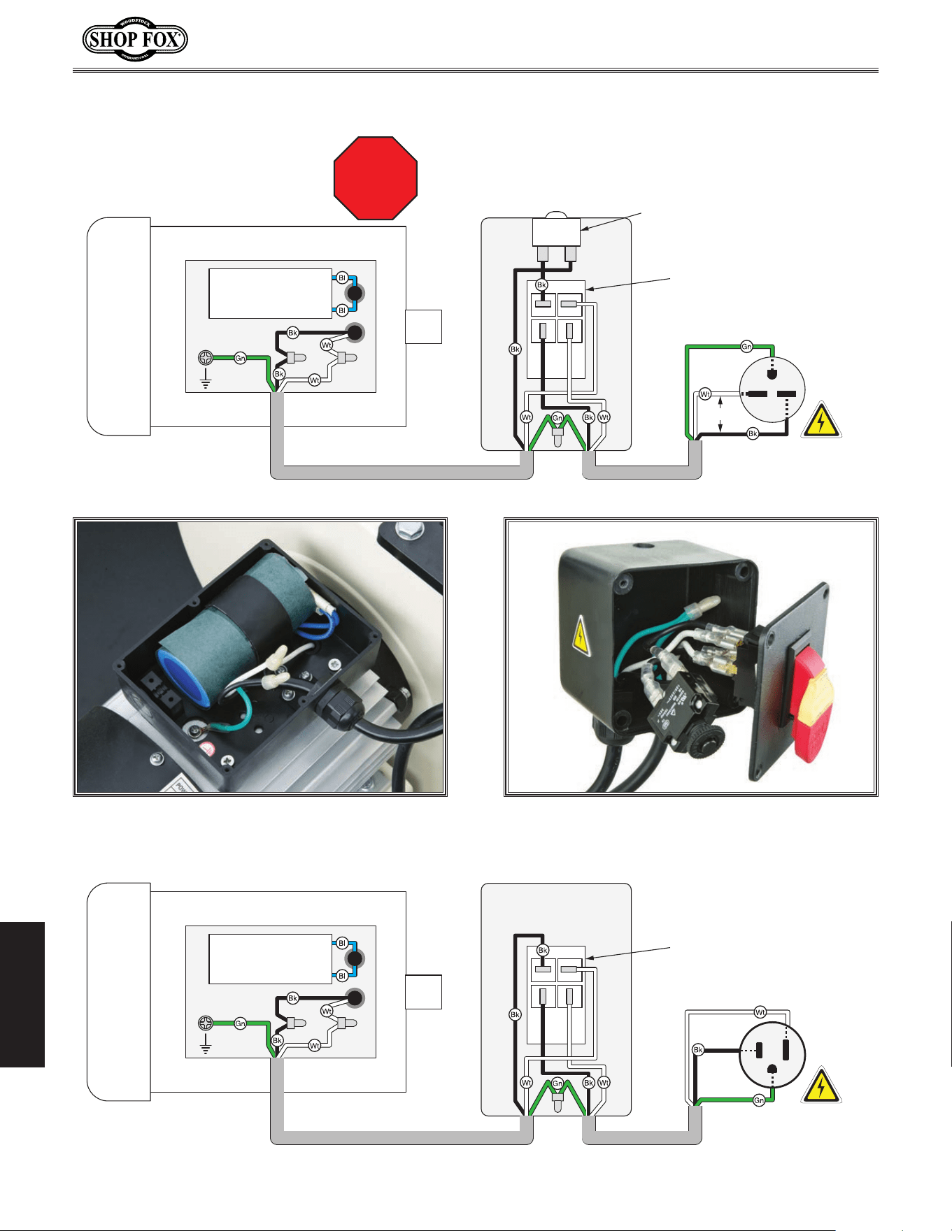
-36-
Model W1666/W1685 (For Machines Mfd. Since 2/15)
SERVICE
220VAC
6-15 Plug
(As Recommended)
Overload Switch
Cruus E209138 18A
Ground
Ground
Hot
Hot
220VAC
220V Motor
Start Capacitor
200MFD 250VAC
G
W1666 Wiring
110VAC
5-15 Plug
(As Recommended)
Ground
Hot
Ground
Neutral
110V Motor
Switch Box
Switch Box
Start Capacitor
600MFD 125VAC
W1685 Wiring
Paddle ON/OFF
Switch
Cruus 5E4
Paddle ON/OFF
Switch
Cruus 5E4
STOP
Read
Page 35
Before
Wiring
Wiring.Diagrams
Figure.39. Motor wiring. Figure.40. Switch wiring.
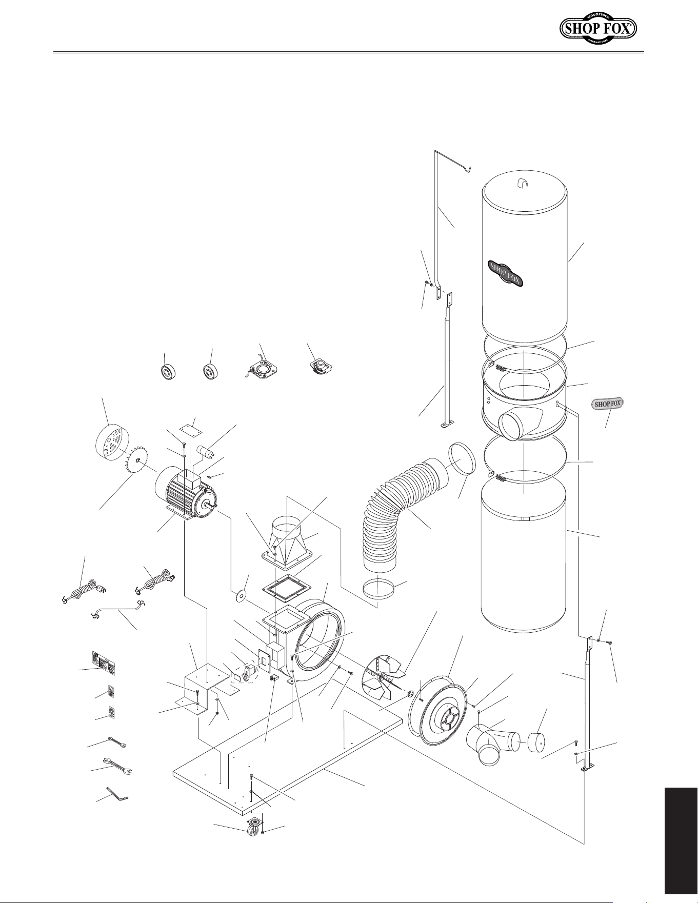
-37-
Model W1666/W1685 (For Machines Mfd. Since 2/15)
PARTS
1
19
4
5
6(W1666)
50(W1685)
16(W1666)
4(W1685)
49
2
24B
18
19
38-1
38-2
9
20
21
23
3
23
24A
38-3
25A
26
27
22B (W1666)
22 (W1685)
38
31
29
30
16
6
42
12
32
43
31
39
40
14
8A-1 (W1666)
8-1 (W1685)
8-5
8-3
8-4
8-14
8-13
15
13
8-6 (W1666)
8A-2 (W1685)
8-11 (W1666)
8A-1 (W1685)
8A
17
36V2
34V2
33
33-1
35V2
34V2
14
48
49
8-10
7-1
7 (W1685)
7 (W1666)
41
10
8-12A
(W1666)
16
6
6
16
6
16
6
16
PARTS
Main
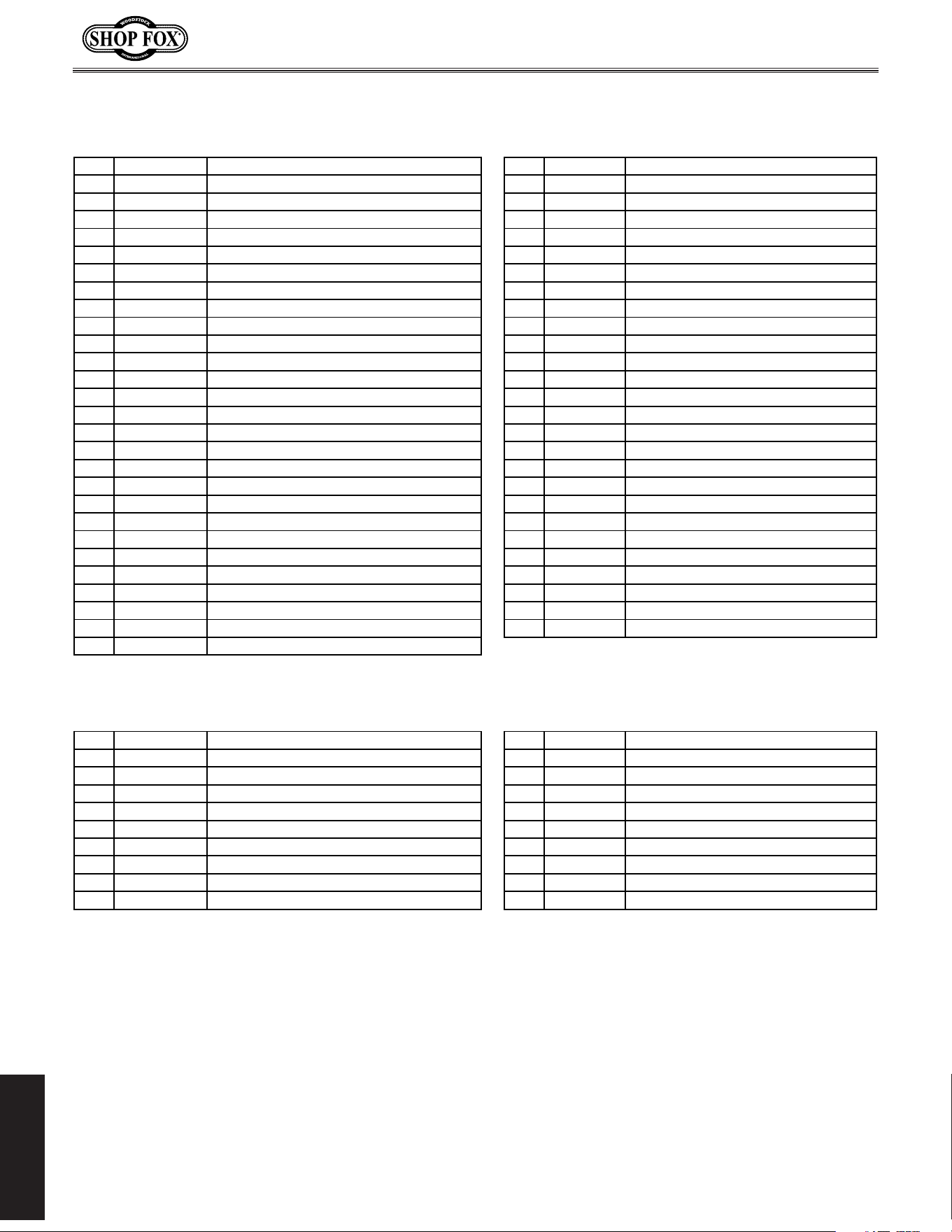
-38-
Model W1666/W1685 (For Machines Mfd. Since 2/15)
PARTS
Main.Parts.List
REF PART # DESCRIPTION REF PART # DESCRIPTION
1 X1666001 SWIVEL CASTER 26 X1666026 CAP SCREW M6-1 X 20 LH
2 X1666002 HEX NUT M8-1.25 27 X1666027 ARBOR WASHER
3 X1666003 BASE PLATE 29 X1666029 OUTLET GASKET 8 HOLE (W1666)
4 X1666004 FLAT WASHER 6MM 29 X1685029 OUTLET GASKET 6 HOLE (W1685)
5 X1666005 MOTOR MOUNT 30 X1666030 OUTLET FLANGE 8 HOLE (W1666)
6 X1666006 HEX BOLT M8-1.25 X 16 30 X1685030 OUTLET FLANGE 6 HOLE (W1685)
7 X1666007 POWER CORD 14G 3W 120" (W1666) 31 X1666031 HOSE CLAMP 5"
7 X1685007 POWER CORD 14G 3W 72" 5-15 (W1685) 32 X1666032 TRANSFER HOSE 5"
7-1 X1666007-1 MOTOR CORD 14G 3W 24" 33 X1666033 SEPARATOR
8-12A X1666008-12A OVERLOAD SWITCH CRUUS 15A (W1666) 33-1 X1666033-1 CURVED SHOP FOX NAME PLATE
9 X1666009 SHOP FOX PADDLE SWITCH 110V W/KEY 34V2 X1666034V2 BAG CLAMP POLYPROPYLENE V2.07.10
10 X1666010 PADDLE SWITCH KEY 35V2 X1666035V2 UPPER BAG 2.5 MICRON V2.02.15
12 X1666012 HEX WRENCH 5MM 36V2 X1666036V2 LOWER BAG (PLASTIC) V2.02.15
13 X1666013 UPPER BAG HANGER 38 X1666038 IMPELLER HOUSING (W1666)
14 X1666014 SEPARATOR SUPPORT 38 X1685038 IMPELLER HOUSING (W1685)
15 X1666015 HEX BOLT M8-1.25 X 25 38-1 X1666038-1 SWITCH BOX
16 X1666016 FLAT WASHER 8MM 38-2 X1666038-2 SWITCH BOX COVER
17 X1666017 KEY 5 X 5 X 25 38-3 X1666038-3 IMPELLER COVER GASKET
18 X1666018 MOTOR SHAFT SPACER 39 X1666039 HAND/INLET WARNING LABEL
19 X1666019 HEX NUT M6-1 40 X1666040 READ MANUAL LABEL
20 X1666020 LOCK WASHER 10MM 41 X1666041 MACHINE ID LABEL (W1666)
21 X1666021 HEX BOLT M10-1.5 X 16 41 X1685041 MACHINE ID LABEL (W1685)
22B X1666022B IMPELLER (W1666) 42 X1666042 WRENCH 8 X 10MM OPEN-ENDS
22 X1685022 IMPELLER (W1685) 43 X1666043 WRENCH 11 X 13MM OPEN-ENDS
23 X1666023 PHLP HD SCR M6-1 X 10 48 X1666048 PHLP HD SCR M5-.8 X 10
24A X1666024A INLET Y-CONNECTOR 6" X (2)4" V2.12.01 49 X1666049 FLAT WASHER 8MM
24B X1666024B INLET Y-CONNECTOR CAP 50 X1685050 HEX BOLT M6-1 X 20
25A X1666025A IMPELLER COVER 6" V2.12.01
W1666 2 HP, 220V, Single-Phase Motor W1685 1-1/2 HP, 110V, Single-Phase Motor
REF PART # DESCRIPTION REF PART # DESCRIPTION
8A X1666008A MOTOR 2HP 220V 1-PH V2.11.02 8A X1685008A MOTOR 1-1/2HP 110V 1-PH V2.11.02
8-3 X1666008-3 CENTRIFUGAL SWITCH 8-3 X1685008-3 CENTRIFUGAL SWITCH
8-4 X1666008-4 CONTACT PLATE 8-4 X1685008-4 CONTACT PLATE
8-5 X1666008-5 MOTOR BOX COVER 8-5 X1685008-5 MOTOR BOX COVER
8-6 X1666008-6 MOTOR FAN COVER 8A-2 X1685008A-2 MOTOR FAN COVER
8-10 X1666008-10 WIRING BOX WITHOUT COVER 8-10 X1685008-10 WIRING BOX WITHOUT COVER
8-11 X1666008-11 MOTOR FAN 8A-1 X1685008A-1 MOTOR FAN
8A-1 X1666008A-1 S CAPACITOR 200M 250V 8-1 X1685008-1 S CAPACITOR 600M 125V
8-13 X1666008-13 MOTOR FRONT BEARING 8-13 X1685008-13 MOTOR FRONT BEARING
8-14 X1666008-14 MOTOR REAR BEARING 8-14 X1685008-14 MOTOR REAR BEARING
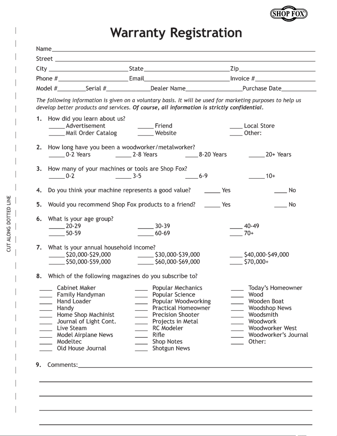
Model W1666/W1685 (For Machines Mfd. Since 2/15)

tape along edges--please do not staple
Fold along dotted lIne
Fold along dotted lIne
Woodstock international inc.
p.o. box 2309
bellingham, Wa 98227-2309
place
stamp
Here

WAR RANTY
Woodstock International, Inc. warrants all Shop Fox machinery to be free of defects from workmanship
and materials for a period of two years from the date of original purchase by the original owner.
This warranty does not apply to defects due directly or indirectly to misuse, abuse, negligence or
accidents, lack of maintenance, or reimbursement of third party expenses incurred.
Woodstock International, Inc. will repair, replace, or arrange for a dealer refund at its expense and
at its option, the Shop Fox machine or machine part, which in proper and intended use has proven to
be defective, provided that the original owner returns the product prepaid to an authorized warranty
or repair facility as designated by our Bellingham, Washington office with proof of their purchase of
the product within two years, and provides Woodstock International, Inc. reasonable opportunity to
verify the alleged defect through inspection. If it is determined there is no defect, or that the defect
resulted from causes not within the scope of Woodstock International Inc.'s warranty, then the original
owner must bear the cost of storing and returning the product.
This is Woodstock International, Inc.’s sole written warranty and any and all warranties that may be
implied by law, including any merchantability or fitness, for any particular purpose, are hereby limited
to the duration of this written warranty. We do not warrant that Shop Fox machinery complies with
the provisions of any law, acts or electrical codes. We do not reimburse for third party repairs. In no
event shall Woodstock International, Inc.’s liability under this limited warranty exceed the purchase
price paid for the product, and any legal actions brought against Woodstock International, Inc. shall be
tried in the State of Washington, County of Whatcom. We shall in no event be liable for death, injuries
to persons or property or for incidental, contingent, special or consequential damages arising from the
use of our products.
Every effort has been made to ensure that all Shop Fox machinery meets high quality and durability
standards. We reserve the right to change specifications at any time because of our commitment to
continuously improve the quality of our products.
WARRANTY