
Contents
1. Features -------------------------------------------------------------------------------------- 2
2. Specification --------------------------------------------------------------------------------- 3
3. How to scan your fingerprint ------------------------------------------------------------ 3
4. Flow chart of menu ------------------------------------------------------------------------ 3
5. Rule of operation---------------------------------------------------------------------------- 4
6. Enroll fingerprint--------------------------------------------------------------------------- 4
7. Delete Fingerprint-------------------------------------------------------------------------- 4
8. Delete all fingerprint ----------------------------------------------------------------------- 5
9. Add User Code ------------------------------------------------------------------------------ 5
10. Delete User Code -------------------------------------------------------------------------- 6
11. Delete All User Code ---------------------------------------------------------------------- 6
12. Set up date and time ---------------------------------------------------------------------- 6
13. Set up Verify Mode ----------------------------------------------------------------------- 6
14. Set up Beep sound ------------------------------------------------------------------------ 7
15. Check user information ----------------------------------------------------------------- 7
16. Change administrator code ------------------------------------------------------------- 7
17. Reset system ------------------------------------------------------------------------------- 7
18. Audit Trail log ----------------------------------------------------------------------------- 7
19. Passage mode enabling/disabling ------------------------------------------------------ 8
20. Key unlock --------------------------------------------------------------------------------- 8
21. Low battery alert ------------------------------------------------------------------------- 8
22. Additional power source ----------------------------------------------------------------- 8
23. System reset -------------------------------------------------------------------------------- 8
24. Troubleshooting --------------------------------------------------------------------------- 8
25. Door preparation------------------------------------------------------------------------ 10
26. Lock installation--------------------------------------------------------------------12
27.Installation Option -----------------------------------------------------------------17
28. Product return ---------------------------------------------------------------17
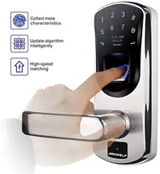
Thank you for choosing fingerprint touchscreen door lock. No more worries
about losing your keys, one touch to unlock. The fingerprint sensor in the lock is
combined with the touch active sensor. This feature allows an easy and fast fingerprint
entry--one touch on the fingerprint sensor unlocks. The lock has self-learning ability,
which enables the lock to update a user fingerprint template after every fingerprint
entry. This unique feature significantly reduces rejection rate when compared to other
fingerprint lock systems on the market. The lock is equipped with OLED display, it
makes visual menu based operation become true. Audit Trail feature allow lock owner
to track entry record. Double verification feature increase lock security level
significantly. Enjoy adopted the latest biometric fingerprint technologies that bring
you a convenient and secure lock system.
1. Features
• Unlock by fingerprint, code, fingerprint + code, fingerprint + fingerprint or key.
• Store up to 256 fingerprint users , include 5 admins, 251 users.
• Store up to 300 user codes in the system.
• Visual menu display on OLED, it makes operation easy.
• Store up to 16384 audit trail logs.
• Individual fingerprint user and user code deletion.
• Build-in touch active sensor: one touch to unlock.
• Self-learning ability: fingerprint template is updated after every fingerprint entry.
• Two ways to login the system: programming code or administrator fingerprint.
• Beeper sound turn off option, you may turn off beeper sound if you don’t like.
• Double verification mode: unlock by User code + fingerprint or fingerprint +
different fingerprint, when you enable this mode.
• Support passage mode: stay at “unlock” state during the passage mode.
• Memory function: “power run-out” or “system reset” will not cause the loss of
enrolled fingerprint(s) and user code(s).
• Reversible lever: lock fits both left-handled and right-handed door.
• Reversing lever controlled by key.
• “Schlage C key” as an override key.
• 9V battery may be attached as an additional power source.
• Double-shell heavy duty construction design.
• OLED show battery level and low battery alert.
2. Specifications
• Optical sensor.
• Touchscreen virtual 12-key keypad.
• Single latch.
• Adjustable backset 2 ⅜” or 2 ¾”.
• Fit door thickness between 1⅜” and 2⅜”.
• Operation temperature from -4˚F (-20˚C) to 151˚F (66˚C).
• All weather door lock.
• Powered by 4 AA Alkaline batteries (NOT included).
• One year limited manufacturer’s warranty.
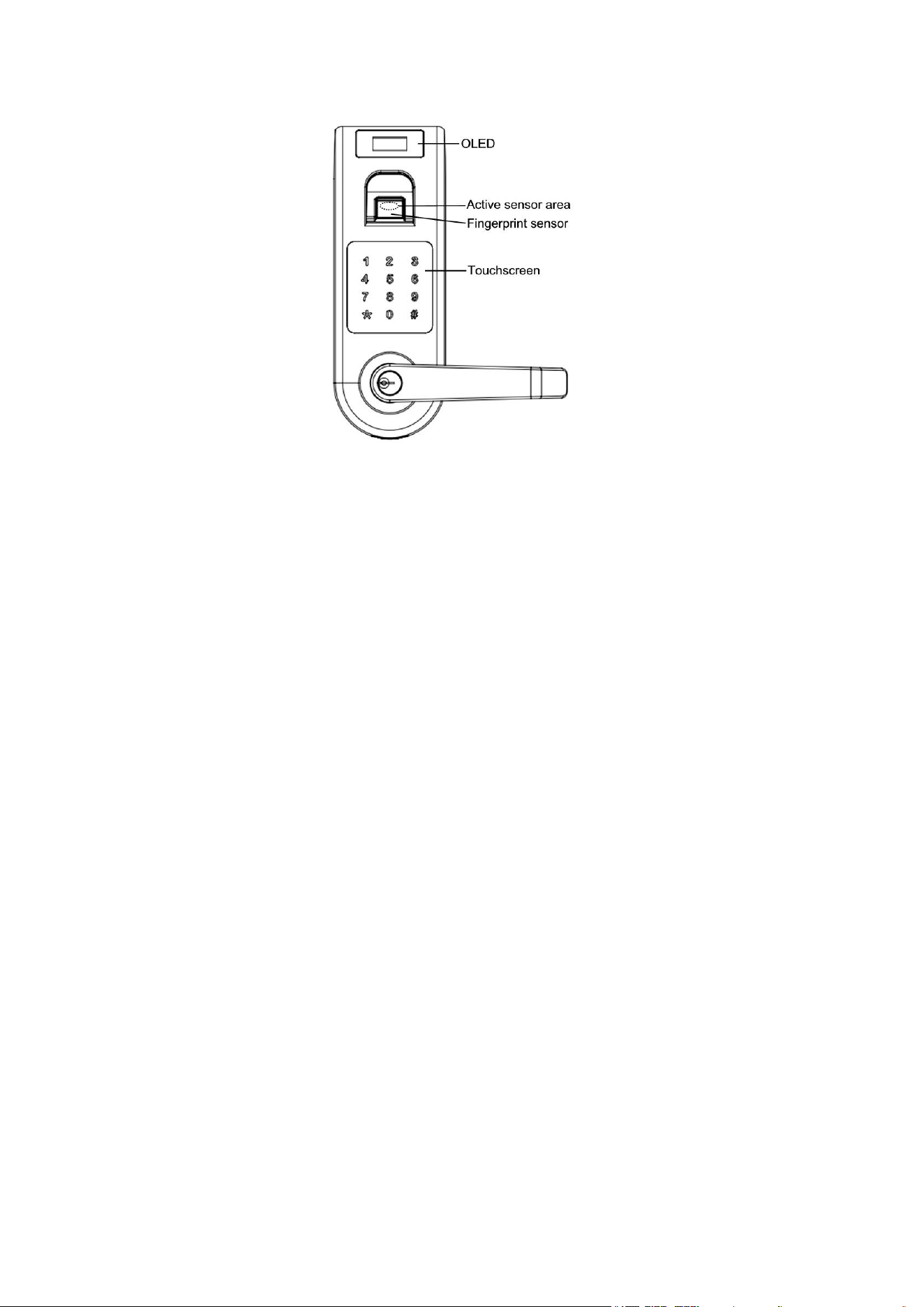
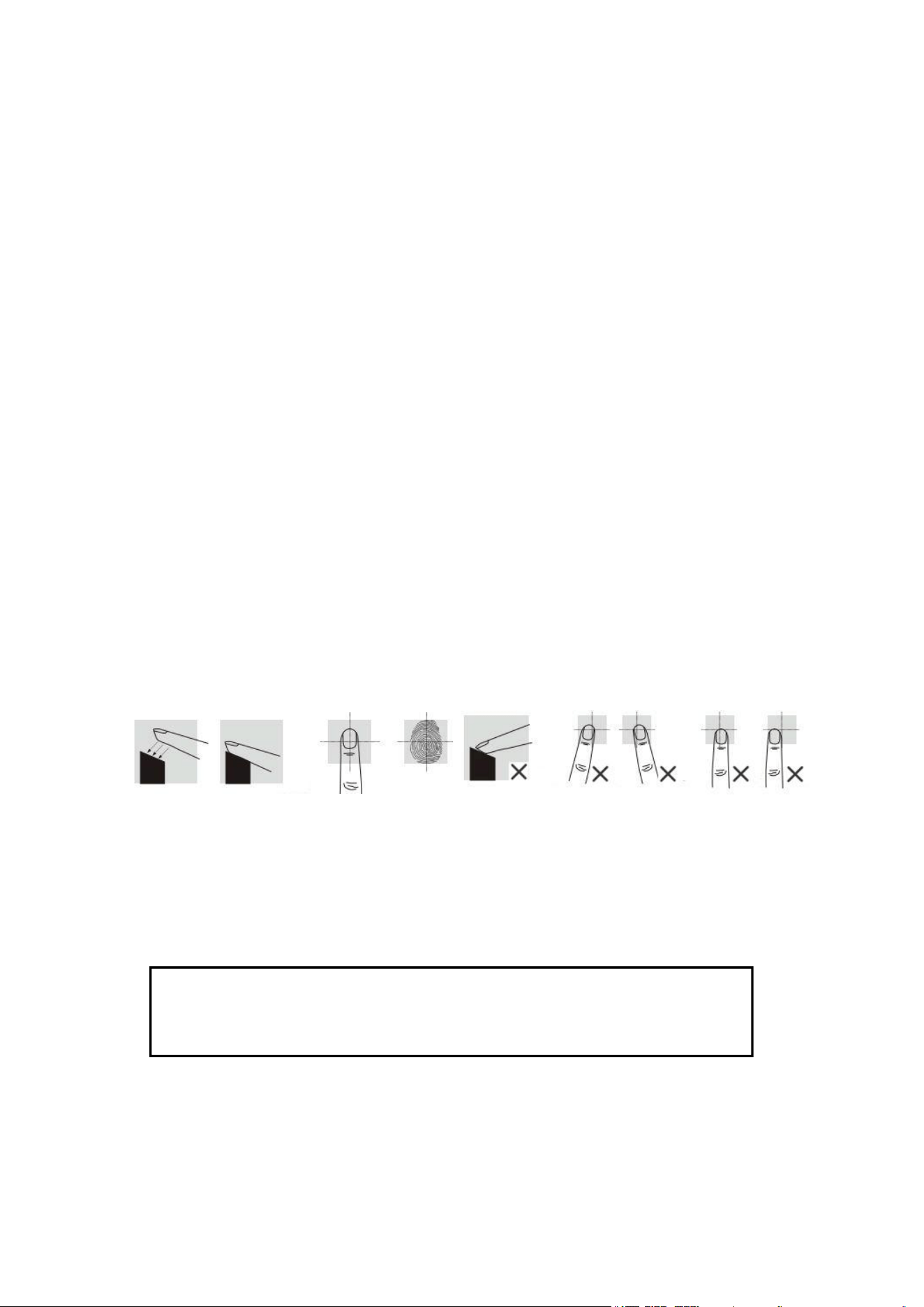
3. How to scan your fingerprint
When you scan fingerprint, make sure that the location of the fingerprint “core”
is making direct contact with fingerprint sensor. Apply medium pressure, or just
enough to flatten the skin on your finger.
We recommend that you register index finger, thumb or finger with visible
fingerprint image. It is important that your finger be clean when registering or
verifying with your fingerprint. Washing your hands with moisturizing soap and using
hand lotion will also improve accuracy.
4. Rule of operation
Note: “2↑” mean that touch 2 to scroll cursor up. “8↓” mean that touch 2 to scroll
cursor down. “# Enter” mean that touch # to confirm.
Login: Active lock by touching screen then touch #. Login page will
show up. Login system by Admin Code or Admin Fingerprint. After
login system, following Menu to program fingerprint, user code or set up
lock. Default administrator code is 1, 2, 3, 4.
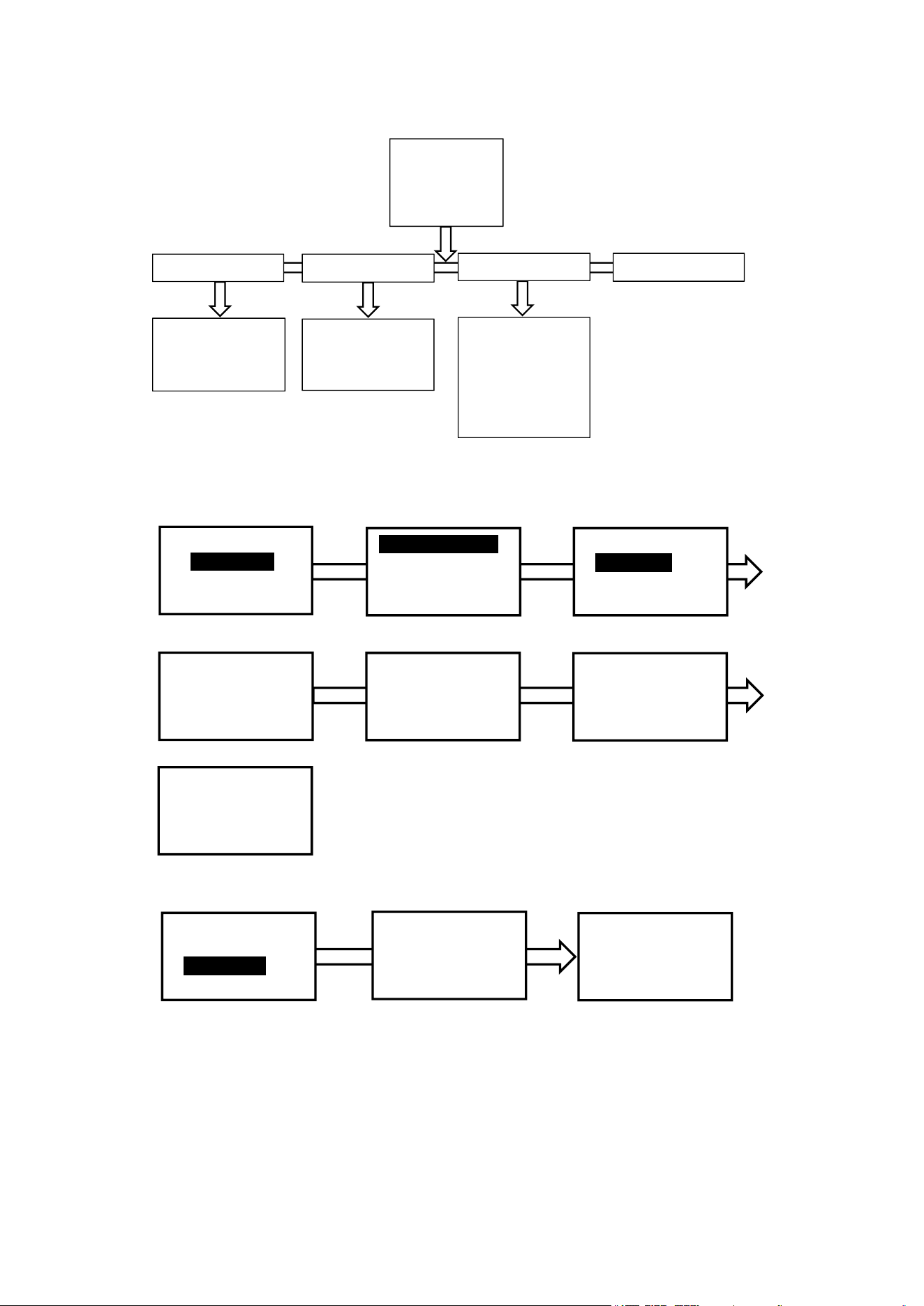
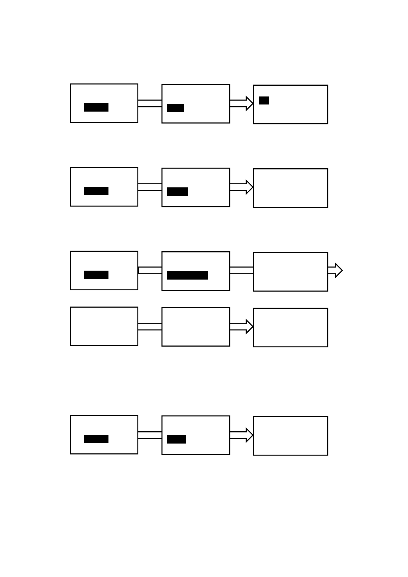
5. Flow chart of menu
6. Enroll fingerprint
Login system, enter menu page (refer page 3 “4. Rule of operation”).
User could input a desired ID
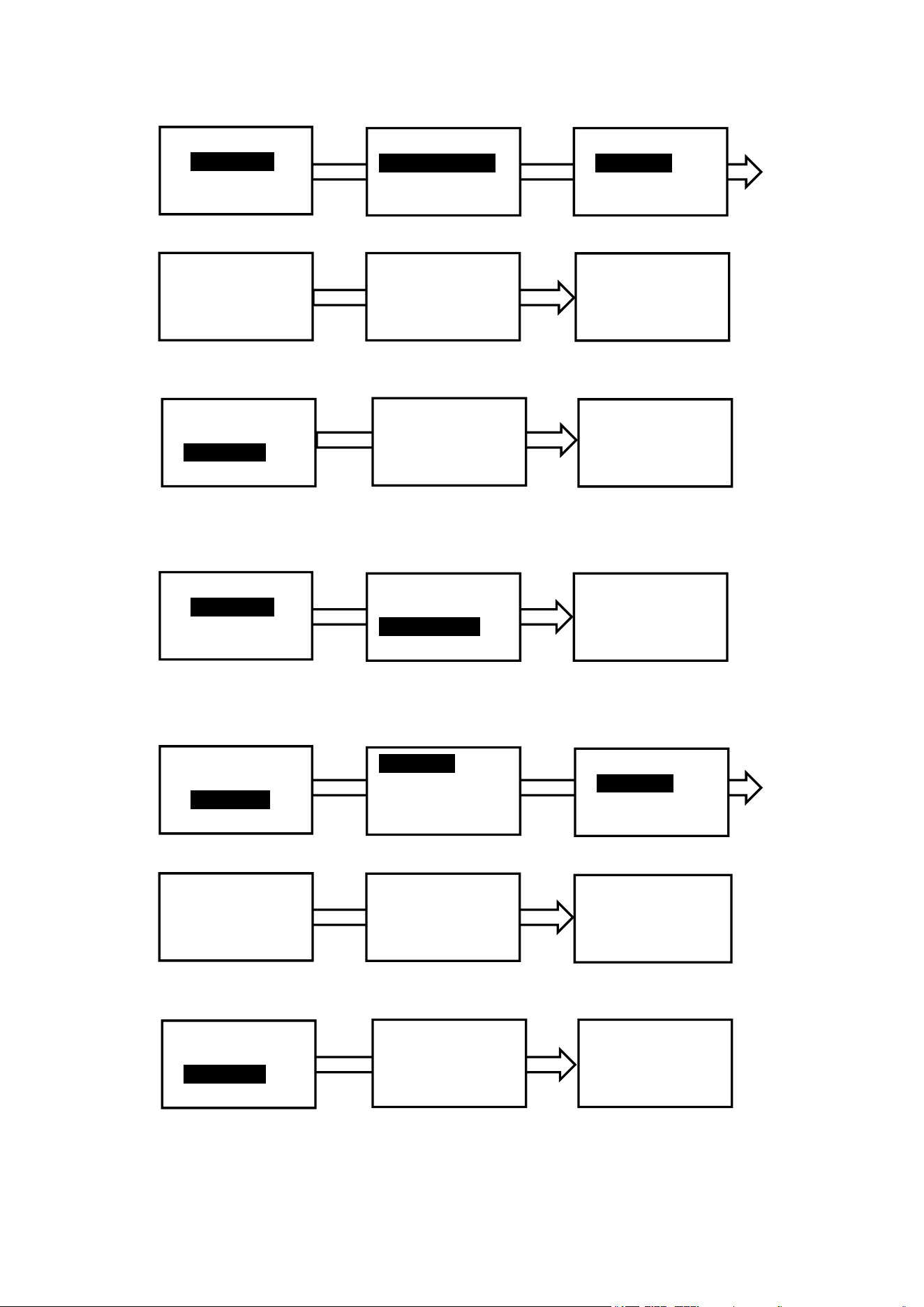
7. Delete Fingerprint
Login system, enter menu page (refer page 3 “4. Rule of operation”).
Fingerprint
User Code
System
AT logs
Enroll Fingerpr.
Delete Fingerpr.
Delete All FP
Menu
Fingerprint
User Code
2↑,8↓, # Enter
Enroll Fingerpr.
Delete Fingerpr.
Delete All FP
2↑,8↓, # Enter
User ID
Pop up ID
Desired ID
2↑,8↓, # Enter
User ID: 001
2↑,8↓, # Enter
User ID: 001
Place finger
on sensor firmly
User ID: 001
Lift and reset
the finger
Successful
Enter user ID
(1 to 256): _ _1
* Exit, # Enter
User ID
Pop up ID
Desired ID
2↑,8↓, # Enter
User ID: 001
Place finger
on sensor firmly
AT log
System
User code
Date & Time
Verify mode
Beep
About
Admin Code
Reset
Add Code
Delete Code
Delete All
Fingerprint
User could input a desired ID
8. Delete all fingerprint
Login system, enter menu page (refer page 3 “4. Rule of operation”).
9. Add User Code
Login system, enter menu page (refer page 3 “4. Rule of operation”).
User could input a desired ID
Menu
Fingerprint
User Code
2↑,8↓, # Enter
Enroll Fingerpr.
Delete Fingerpr.
Delete All FP
2↑,8↓, # Enter
User ID
Pop up ID
Desired ID
2↑,8↓, # Enter
User ID: 001
2↑,8↓, # Enter
Delete User
001_?
* No, # Yes
Successful
Enter user ID
(1 to 256): _ _1
* Exit, # Enter
User ID
Pop up ID
Desired ID
2↑,8↓, # Enter
Delete User
001_?
* No, # Yes
Menu
Fingerprint
User Code
2↑,8↓, # Enter
Enroll Fingerpr.
Delete Fingerpr.
Delete All FP
2↑,8↓, # Enter
Delete All
Fingerprint ?
* No # Yes
Menu
Fingerprint
User Code
2↑,8↓, # Enter
Add Code
Delete Code
Delete All
2↑,8↓, # Enter
Code ID
Pop up ID
Desired ID
2↑,8↓, # Enter
ID: 001
2↑,8↓, # Enter
Enter Code
(4-12 digit)
*******
* Exit # Enter
Enter Code again
(4-12 digit)
*******
* Exit # Enter
Enter user ID
(1 to 300): _ _1
* Exit, # Enter
Code ID
Pop up ID
Desired ID
2↑,8↓, # Enter
Enter Code
(4-12 digit)
*******
* Exit # Enter
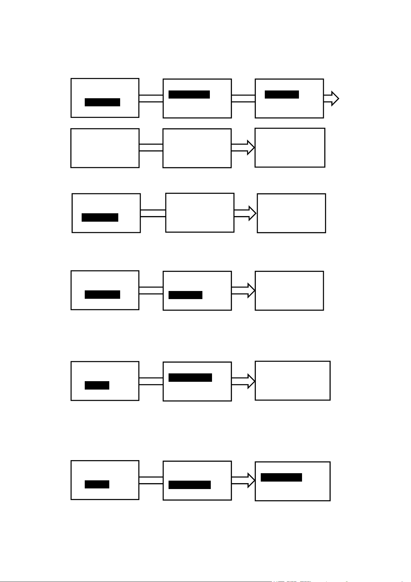
10. Delete User Code
Login system, enter menu page (refer page 3 “4. Rule of operation”).
System allow user input a desired ID
11. Delete All User Code
Login system, enter menu page (refer page 3 “4. Rule of operation”).
12. Set up date and time
Login system, enter menu page (refer page 3 “4. Rule of operation”).
Input number, the default number will be replaced.
13. Set up Verify Mode
Login system, enter menu page (refer page 3 “4. Rule of operation”).
The verify mode are fingerprint or user code, fingerprint + code and fingerprint +
fingerprint, You may pick up one that you want.
Menu
Fingerprint
User Code
2↑,8↓, # Enter
Add Code
Delete Code
Delete All
2↑,8↓, # Enter
Code ID
Pop up ID
Desired D
2↑,8↓, # Enter
ID: 001
2↑,8↓, # Enter
Delete Code
***_?
* No, # Yes
Successful
Enter user ID
(1 to 300): _ _1
* Exit, # Enter
Code ID
Pop up ID
Desired ID
2↑,8↓, # Enter
Delete Code
***_?
* No, # Yes
Menu
Fingerprint
User Code
2↑,8↓, # Enter
Add Code
Delete Code
Delete All
2↑,8↓, # Enter
Delete All?
* No # Yes
Menu
User Code
System
2↑,8↓, # Enter
System
Date & Time
Verify Mode
2↑,8↓, # Enter
Date & time
Date: dd/mm/yyyy
Time: hh/mm/ss
* Exit, # Confirm
Menu
User Code
System
2↑,8↓, # Enter
System
Date & Time
Verify Mode
2↑,8↓, # Enter
Verify Mode
Finger/Code
Finger+Code
2↑, 8↓, # Enter
14. Set up Beep sound
Login system, enter menu page (refer page 3 “4. Rule of operation”).
You may turn on or off sound.
15. Check user information
Login system, enter menu page (refer page 3 “4. Rule of operation”).
You may check user information in “About” under the system.
16. Change administrator code
Login system, enter menu page (refer page 3 “4. Rule of operation”).
Please change default administrator code (1, 2, 3, 4) after you set up lock..
17. Reset system
Login system, enter menu page (refer page 3 “4. Rule of operation”).
You may reset system to manufacture default. All audit logs will be removed after
reset but all fingerprint and user code will remain in system. Administrator code will
revert to default code 1, 2, 3, 4. You may use delete all command to remove all finger
or user code from system.
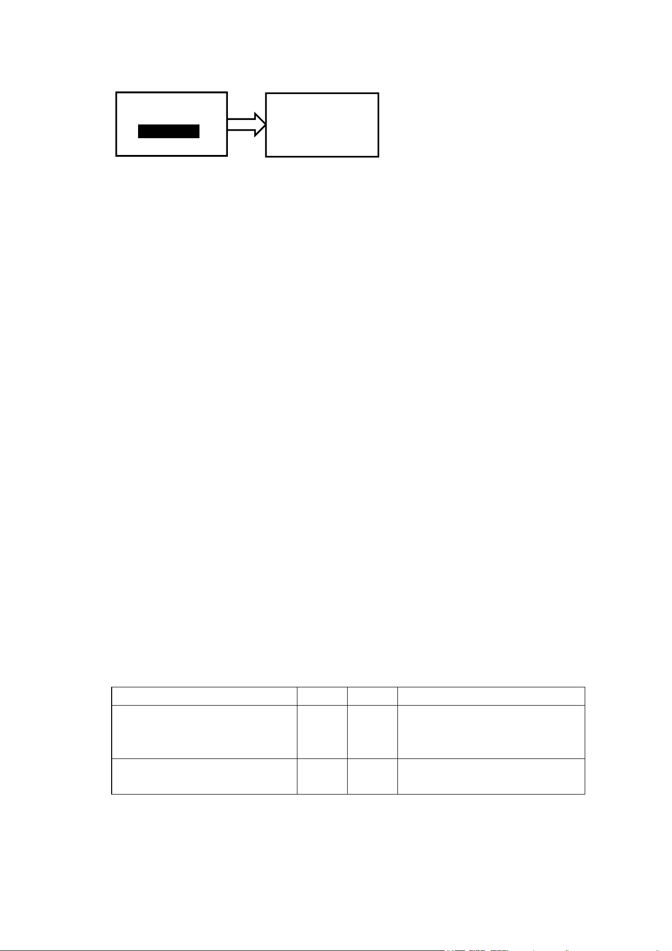
18. Audit Trail log
Login system, enter menu page (refer page 3 “4. Rule of operation”).
You may check audit trail logs on lock directly. Touch “2” or “8” to page up or
down.
Menu
User Code
System
2↑,8↓, # Enter
System
Verify Mode
Beep
2↑,8↓, # Enter
Beep
On
Off
2↑, 8↓, # Enter
Menu
User Code
System
2↑,8↓, # Enter
System
Beep
About
2↑,8↓, # Enter
Admin Finger
Capacity: 3
Admin: 1
2↑, 8↓, * Exit
Menu
User Code
System
2↑,8↓, # Enter
System
User info
Admin code
2↑,8↓, # Enter
Current Code
_ _ _ _ _ ****
* Exit, # Enter
Enter New Code
_ _ _ _ _ ****
* Exit, # Enter
Enter again
_ _ _ _ _ ****
* Exit, # Enter
Successful
Menu
User Code
System
2↑,8↓, # Enter
System
Admin code
Reset
2↑,8↓, # Enter
Reset ?
Press # to confirm
19. Passage mode enabling/disabling
The lock can be set at a passage mode. When the lock is in a passage mode,
anybody could open the door by pushing down the lever.
To enable a passage mode, press
*
within 5 second after any user unlocks the
lock by using either a fingerprint or a user code. Any user unlocks the lock by using a
fingerprint or a user code will disable a passage mode,
20. Key unlock
Insert a key in the cylinder to rotate 180° CLOCKWISE, then rotate lever to
unlock. Rotate a key 180° COUNTER CLOCKWISE then take out the key to lock.
21. Low battery alert
Icon show battery level, remind user to change battery when low battery.
22. Additional power source
When power runs out, attach 9V battery to the ports that are located at the
bottom of the lock to power up the system.
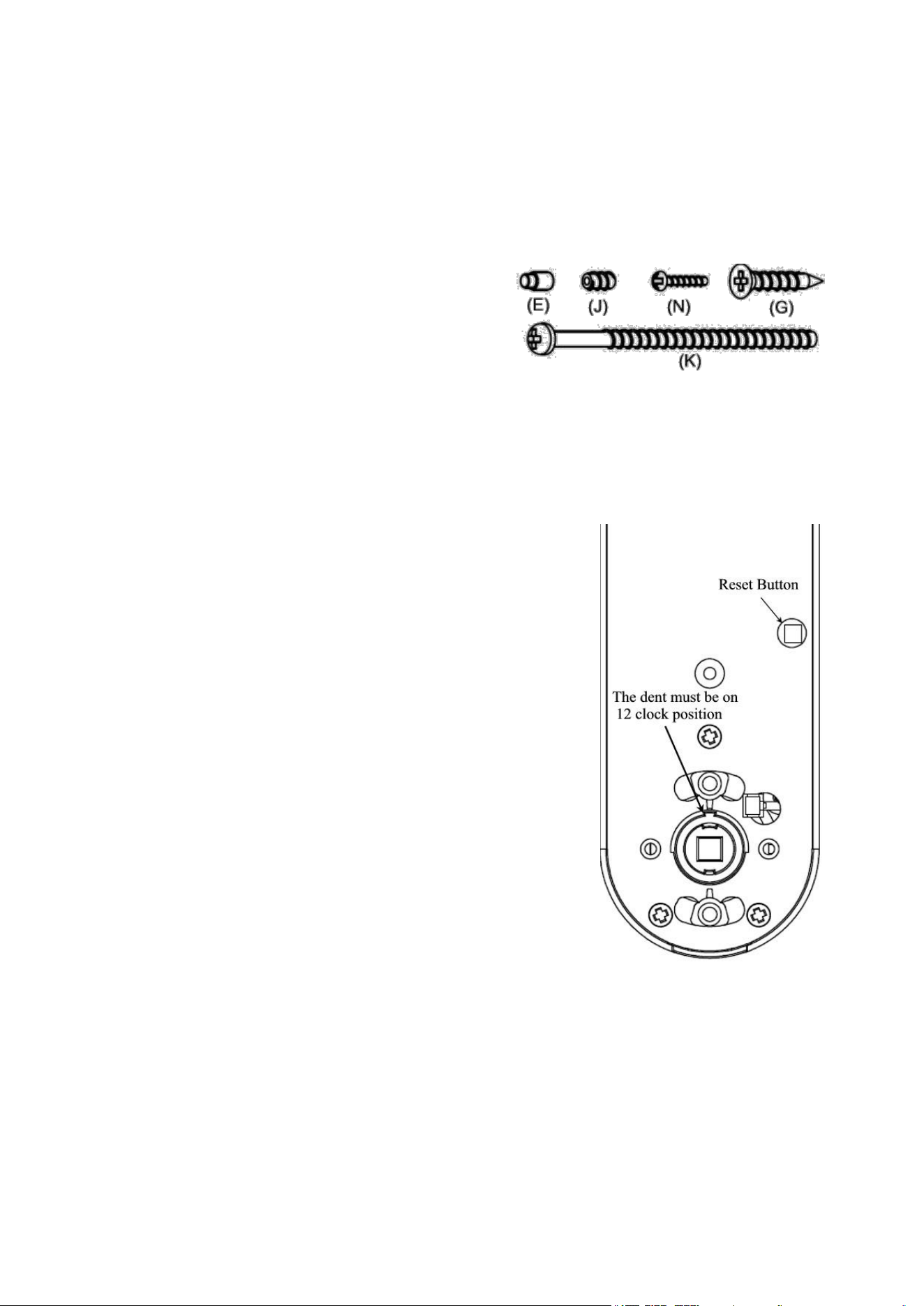
23. System reset
If you can’t login the system, the system can be reset to the factory-set default
mode by pressing the reset button. To reset the system, press the reset button and hold
until you hear a long beep. The reset button is located on the PCB board. If you’ve
already installed the lock onto a door, you will need to take the lock off the door in
order to locate the reset button. After resetting the system, administrator code will
revert back to the default code (1,2,3,4). All user fingerprints and user codes will
remain in the system. You may login by using default administrator code to use
command to delete all fingerprint or user code when you need it.
24. Troubleshooting
Problem
Beeps
Lights
Solution
Nothing happens when finger is
placed on the fingerprint
sensor.
None
None
Lift the finger then place the
finger on top of the sensor.
Nothing happens when
numbers are pressed.
None
None
Wait for 5 seconds
Menu
System
Audit Logs
2↑,8↓, # Enter
FP ID
:
001
Date: 06/20/2016
Time: 21:23:16
↑(2) 00012 (8)↓

Can’t login by programming
code.
Two
Red
Enter a valid Code. Reset system
if you forgot programming code.
Can’t login by administrator
fingerprint.
Two
Red
Login with a fingerprint ID as 0,
1, 2, 3, 4 or 5.
You hear two short beeps and
see red light after enter user ID
Two
Red
ID has been used. Try a different
ID.
Can’t program my fingerprint.
Two
Red
Try to program a different finger
Can’t unlock by my fingerprint.
Two
Red
Try to place your finger on a
different area or at a different
angle.
Can’t unlock by a User Code.
Two
Red
Try a different User Code.
System exits active status.
None
Red
Nothing to do.
Lock stays as unlock.
None
None
Unlock by a User Code or a
fingerprint. Take off front lever
then follow instruction step by
step to setup lever again if the
lock still stays as unlocked.
Can’t rotate rear lever up or
down.
None
None
Installation error, please refer to
the installation instruction and
re-install the lock.
System crash. The system
doesn’t accept any command.
None
None
Take one battery out, press any
key for 2 seconds, and then place
the battery back.
Battery hot or battery
compartment melt
None
None
Remove battery immediately.
Take off lock from door, check
wire if it is pinched or crushed.
Contact manufacturer.
Front lever was pulled out
None
None
User must rotate key 180 degree;
the lever may be pulled out if
user rotates key 90 degree
instead of 180 degree.
No power after placing battery
in.
None
None
Check wire connection and
check battery if it is put in
backward.
During lever set up, you think
key short and need to modify
None
None
Refer fig. 6 on page 15 to do step
3.2. The key do not need any
modification.
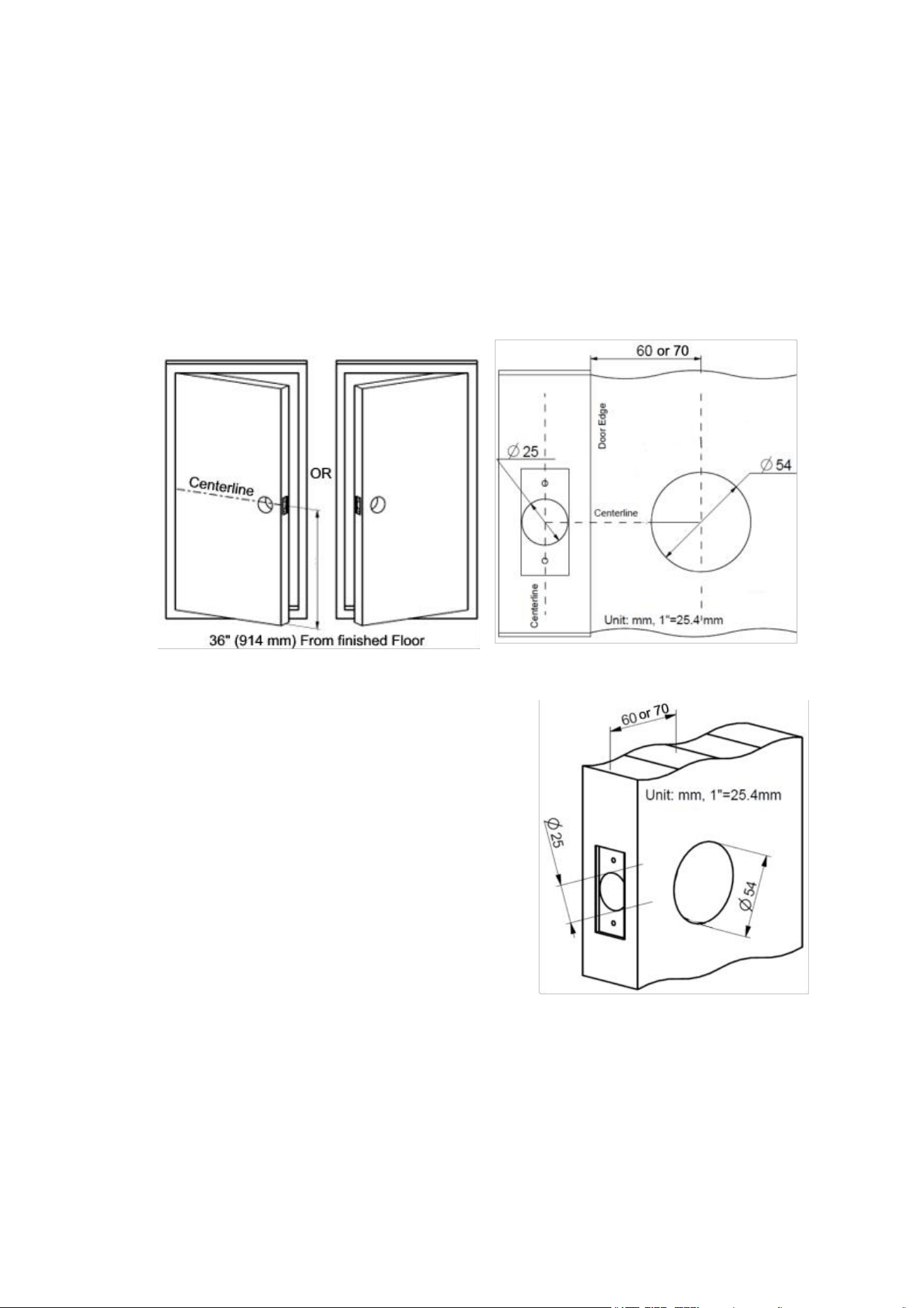
25. Door preparation
Tools needed for new installation:
Pencil, Chisel, Tape Measure, Hammer, Phillips Screwdriver, 1” (25 mm) & ⅛” (3
mm) Drill Bits, 2 ⅛” (54 mm) Hole Boring Bit, Power Drill.
1. Mark door.
1.1 Mark centerline on door and jamb (see fig. 1).
1.2 Stand so door swings towards you.
2. Drill holes on door (see fig. 2, and 3).
fig. 1
fig. 2
3. Install Latch.
3.1 Latch is adjustable, you may set the latch to
either 2 ⅜” (60 mm) or 2 ¾” (70 mm) backset
(see fig.4).
3.2 Use faceplate as a pattern for mortise and
pilot holes. The faceplate should fit flush (see
fig. 5).
3.3 Install as shown for appropriate latch type.
Ensure bevel faces door jamb.
3.4 Check square hole edge on the latch
spindle. The square hole edges MUST are
either parallel or Vertically aligned with latch
centerline (see fig. 6), otherwise refer fig. 7 to
adjust latch spindle.
fig. 3
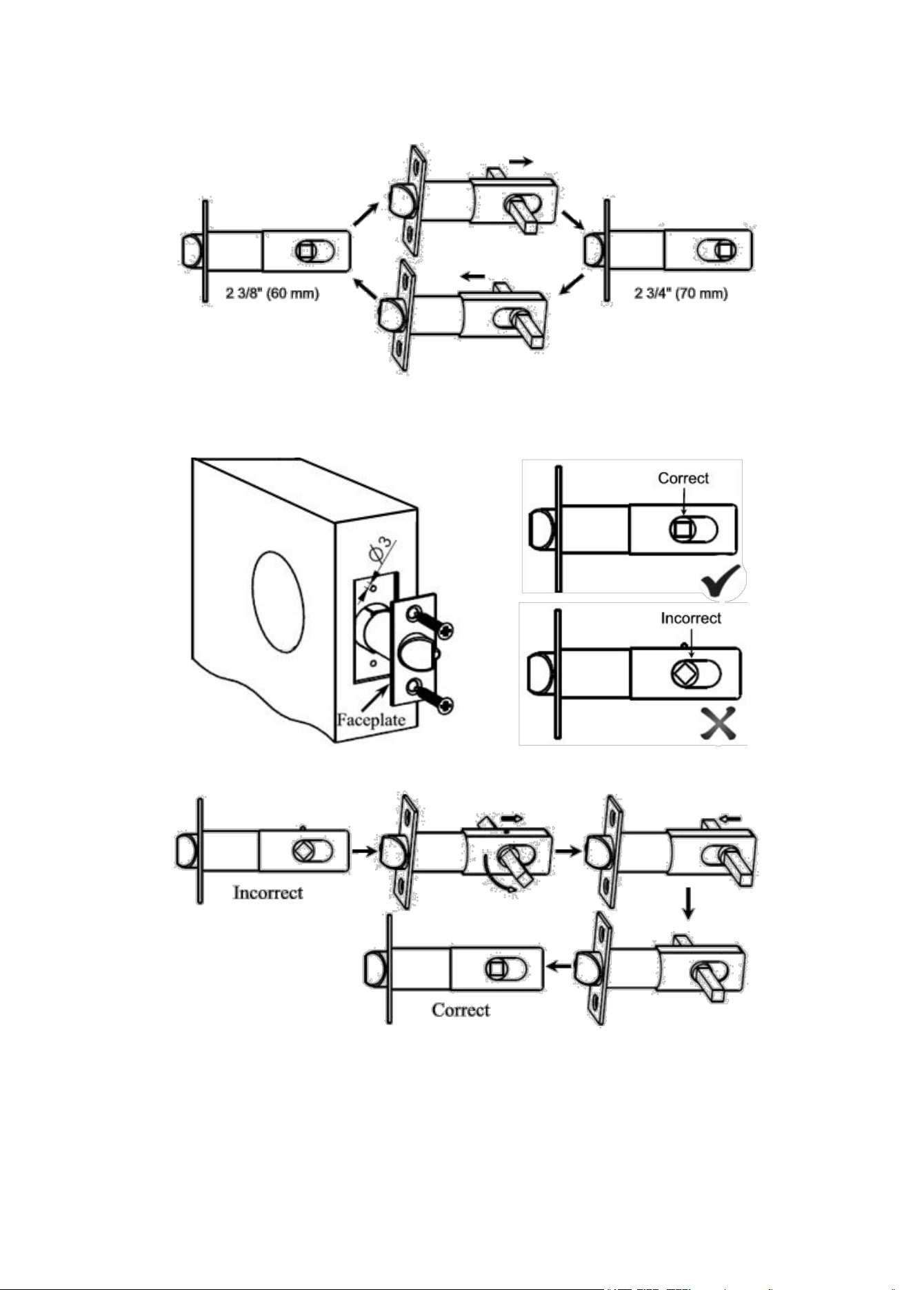
fig. 5
fig. 6
fig. 7
fig. 4
4. Prepare door jamb (see fig. 8).
4.1 Mark centerlines on jamb exactly opposite center of latch hole.
4.2 Make rectangle holes as shown.
4.3 Use strike as a pattern for mortise and pilot holes. Strike should fit flush.
fig. 8
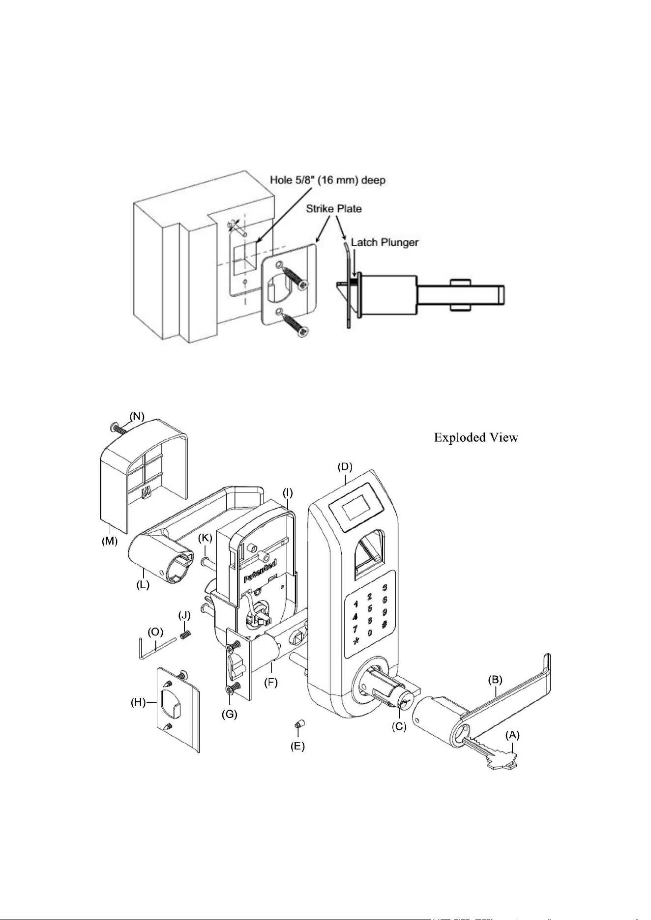
26. Lock installation
(A) Key
(B) Outside Lever
(C) Cylinder
(D) Outside chassis
(E) Lever Catch
(F) Latch
(G) Latch/Strike Screws
(H) Strike
(I) Inside chassis
(J) Allen Screw
(K) Mounting Screws
(L) Inside Lever
(M) Cover
(N) Cover Screw
(O) Allen Wrench (Tool)
The lock comes with two (K) Mounting Screws
M5x60, 2⅜” (60 mm) long, one (N) M3x25,
1”(25 mm) long Cover Screw, one (J) Allen
Screw, one (E) Lever Catch and 4 pieces (G)
Latch/Strike Screws.
Note: Lock fit door thickness from 1⅜” to 2⅜”.
Contact us to order M5x50
,
2” (50 mm) long screw if door thickness is less than 1⅜”.
Tools needed: Phillips Screwdriver, Tape Measure, Pencil, and Flathead Screwdriver.
IMPORTANT NOTES:
DO NOT use a power drill for installation !
Install and test lock with door open to avoid being locked out.
1. Install lock on the door.
1.1 The dent should be on 12-clock position (see fig. 1),
if not, rotate Square Spindle to let the dent be on
12-clock position.
1.2 Install the outside chassis unit (see fig. 2). Slide
wire through hole on door. Slide square spindle and
poles smoothly through holes in latch. Take care to
keep outside chassis vertically aligned during
installation. Check latch setting and door dimensions if
there is any problem.
1.3 Take care to keep inside chassis vertically aligned
during installation. Connect wire and arrange wire in
empty space, take care to ensure wire is not pinched or
crushed at any point during installation. The Square
Spindle slide smoothly into square hole on Lever
Spindle (see fig. 3).
1.4 Insert Mounting Screws to mounting hole on the
inside chassis (see fig. 4), screws should slide smoothly
through hole on door. Use Philip Driver to drive two
screws into mounting hole on mounting poles.
fig. 1
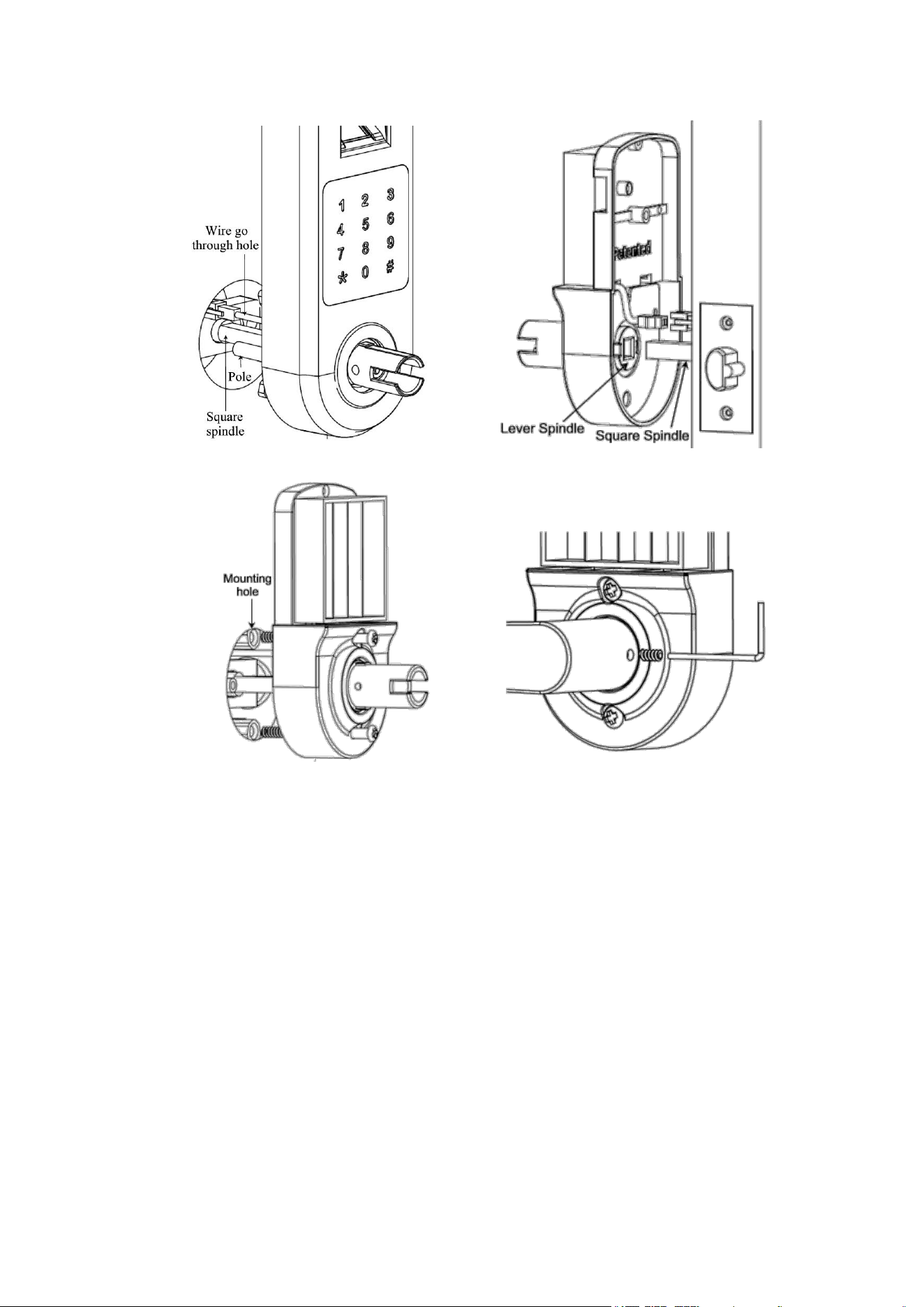
fig. 4
fig. 5
2. Set up inside Lever: Put Lever on Lever Spindle then use Allen Wrench to put
Allen Screw (see fig. 5). Reverse the step when you want to remove Lever.
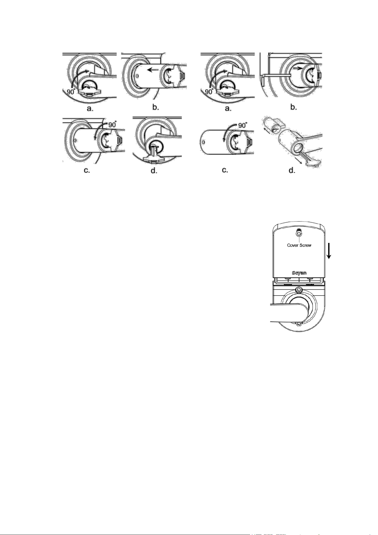
3. Set up outside Lever: Set up lever to fit for either left-handed or right-handed door.
3.1 Make sure that the dent is on 12-clock position when lock hasn’t be installed on
the door (see fig. 1), if not, rotate Square Spindle.
3.2 Rotate inner Spindle by Flathead Screwdriver let Cylindrical Protrusions
horizontally aligned (see fig. 6).
3.3 Insert Lever Catch in the right side hole on Lever Spindle completely if your
door is left-handed (see fig. 7a), otherwise put it in the left side hole (see fig. 8a). The
big end on the Lever Catch goes into the hole first.
fig. 2
fig. 3
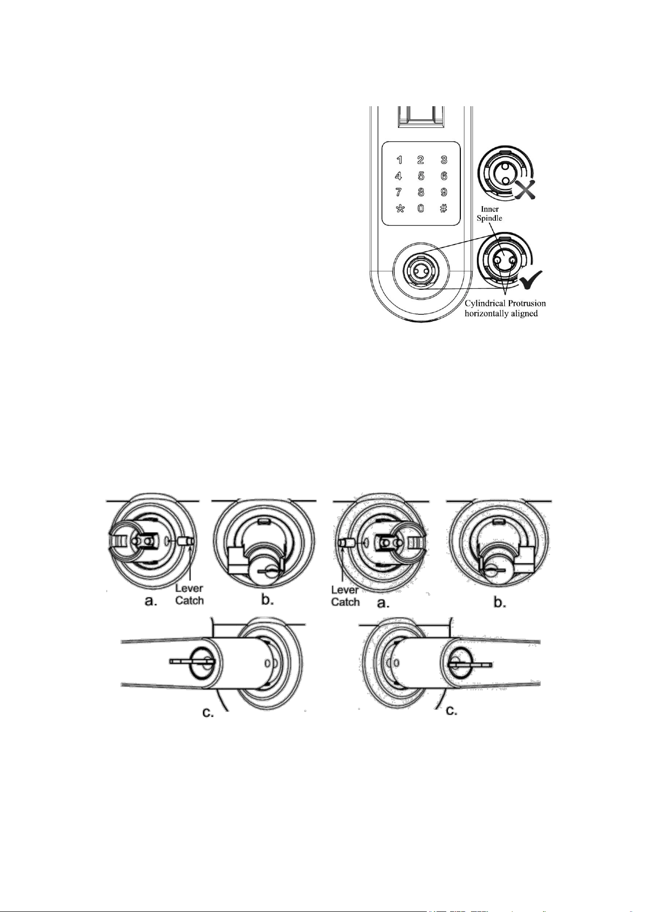
out (see fig. 9d). The Lever will stay on the lock and can’t be pulled out after Lever is
set up properly.
3.6 Remove Lever (if necessary): Refer fig.1 to make sure that the dent is on
12-clock if the lock hasn’t been installed on the door. Insert key into Cylinder then
rotate key CLOCKWISE 90°, use Allen Wrench or paper clip to push Lever Catch
then pull lever out (see fig.10). Rotate key COUNTER CLOCKWISE 90° then take
key out. Use Flathead Screwdriver to rotate Cylindrical Protrusions, the Lever Catch
will protrude. Take the Lever Catch out, keep it in safe place.
fig. 7
fig. 8
3.4 Insert Cylinder in Lever Spindle. The
Cylinder’s tail toward left if you want to set lock
as left-handed (see fig. 7b), otherwise the
Cylinder’s tail toward right (see fig. 8b).
3.5 Put lever on Lever Spindle (see fig. 7c,
8c). The lever will stop at half way when you
push Lever in. (Caution: Refer fig. 6 to do step
3.2 if Cylinder has hidden in lever, key can’t
be inserted completely and rotated.) Insert
key into Cylinder, rotate the key CLOCKWISE
90° (see fig. 9a), continue rotating key while
pushing lever until the lever is pushed in (see
fig. 9b). The key rotating rang is from 90° to
135°
.
Rotate key counter CLOCKWISE back
to original position (see fig. 9c) then take key
fig. 6
3.7 Switching Levers (if necessary): Levers can be reversed to extend toward
hinges.
Refer 3.6 to remove lever then following 3.1 to 3.5 to set up lever.
4. Install 4 brand new AA Alkaline batteries (NOT included, do not
use rechargeable batteries). Alkaline Batteries Warning: Do not
install backwards, charge, put in fire, or mix with other battery
types, may explode or leak causing injury. Replace all batteries at
the same time.
5. Slide cover down then tight cover screw (see figure 11).
6. Testing lock: Rear lever should be pushed down and lifted up;
otherwise take off lock to re-install it by referring fig.1 to rotate
Square Spindle to let the dent be on 12-clock position. The lock
may keep unlock after installation. Enter default code 1234 then
press #. The lock will lock by itself after 5 second. Installation
error occurs if the lock still unlock. Refer 3.6 to remove lever then
follow instruction step by step to setup front lever. Push down rear
fig. 11
lever the latch should retract completely; otherwise check latch if it is broken.
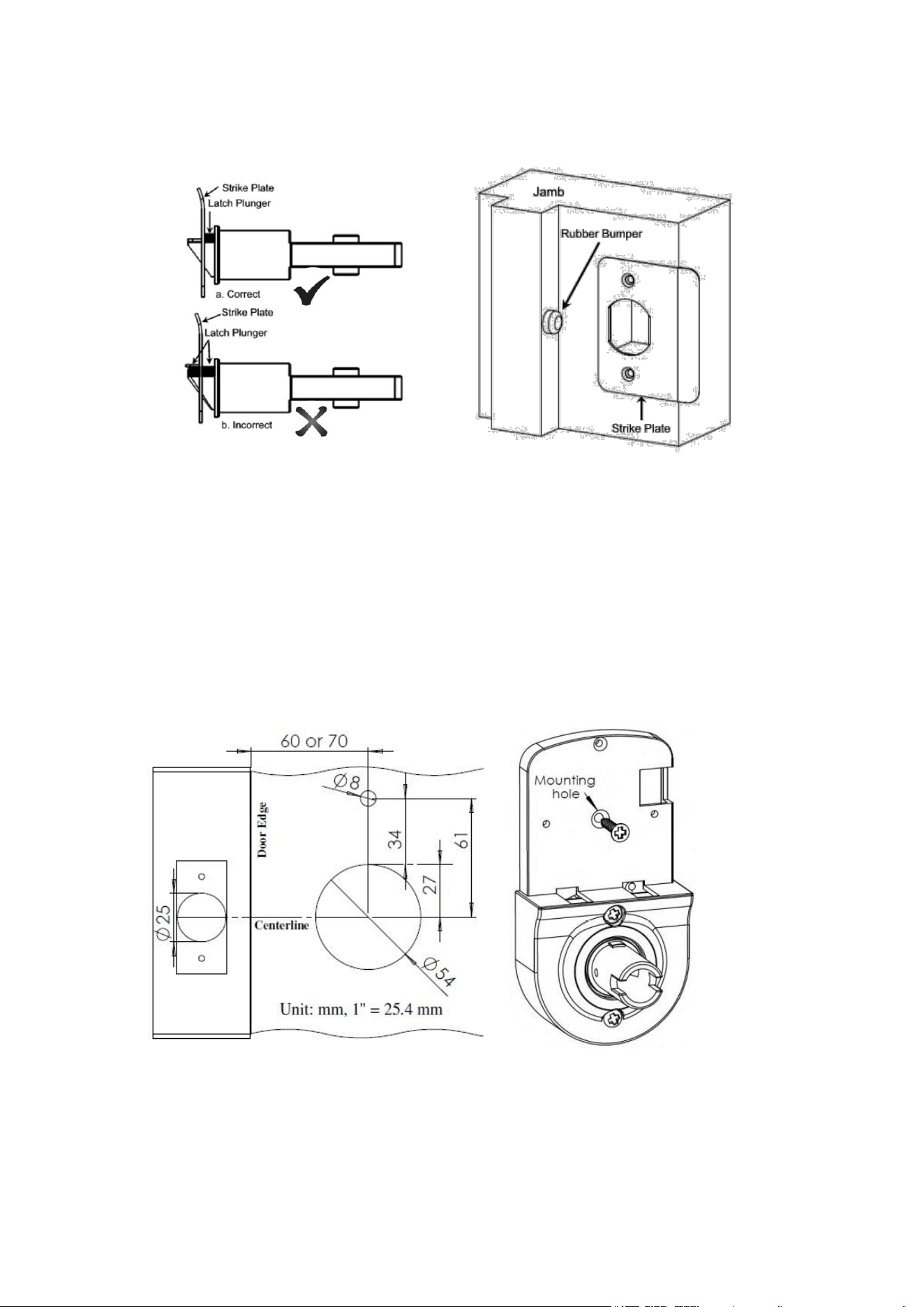
7. Caution: Please install strike plate included in package. The existing strike must
be removed if there is one on door jamb. Check the operation of the latch by ensuring
that the latch plunger stops against the strike plate and does not slide into the strike
opening when the door is closed (see fig. 12). If that situation occurs, then a total
lockout may occur. This situation will void our warranty of the complete lock
mechanism. If necessary, correct the door over-travel by using the rubber bumper (see
fig. 13). You may buy the rubber bumpers from your local hardware store.
fig. 9
fig. 10
8. Lock removal: Reverse step 5, 4 and 2. Refer step 3.6 to remove outside Lever.
Reverse step 1.4 and 1.3 to remove outside chassis and inside chassis from the door.
27. Installation Option
The lock will stay on vertical position on the door as long as the two mounting
screws were tightened in most case. You may put a screw and hex screw between
inside chassis and out chassis to increase lock stability.
27.1 Remove two screws in battery compartment. You will see mounting hole
under battery compartment.
27.2 Use ⅓" (8 mm) Drill Bits to drill a hole in the mounting hole position (fig. 14).
27.3 Tighten hex screw on back plate of outside chassis, tighten M4x40 (40mm
long) screw through mounting hole (fig. 15) with hex screw.
27.4 Put battery compartment back.
fig. 14
fig. 15
fig. 12
fig. 13

28. Product return
Please refer installation instruction to remove lock from door, remove levers from
lock. Use Mounting Screws to put outside and inside chassis together, insert outside
and inside Lever on Lever Spindle. Put them back to original package. All accessories
go in small box. We appreciate that you help us to pack lock well.