Loading ...
Loading ...
STOPPING
ÀÀ Move equipment control or any ignition stop switch on engine to
“STOP” or “OFF” (see equipment manufacturer’s instructions).
ÁÁ AFTER ENGINE IS STOPPED:
A. Close fuel valve (if so equipped).
B. DISCONNECT SPARK PLUG WIRE FROM SPARK PLUG
AND KEEP IT AWAY FROM SPARK PLUG.
C. TURN IGNITION SWITCH KEY (IF SO EQUIPPED) TO
“OFF” POSITION AND REMOVE KEY FROM SWITCH,
THIS WILL REDUCE THE POSSIBILITY OF
UNAUTHORIZED STARTING OF ENGINE WHILE
EQUIPMENT IS NOT IN USE.
NEVER STORE ENGINE WITH FUEL IN TANK INDOORS
OR IN ENCLOSED, POORLY VENTILATED AREAS,
WHERE FUEL FUMES MAY REACH AN OPEN FLAME,
SPARK OR PILOT LIGHT AS ON A FURNACE, WATER
HEATER, CLOTHES DRYER OR OTHER GAS APPLIANCE.
MAINTENANCE
WARNING: TEMPERATURE OF MUFFLER AND NEARBY
AREAS MAY EXCEED 150
0
F (65
0
C). AVOID THESE AREAS.
ÀÀ OIL LEVEL:
Check oil level every five (5) operating hours and before each
use. See “FILL OIL SUMP OR CHECK OIL LEVEL’’ on Page 2.
ÁÁ CHANGE OIL:
Change oil after first two (2) operating hours and every 50
operating hours thereafter, more often if operated in extremely
dusty or dirty conditions. Change oil while engine is still warm
from recent running.
A. DISCONNECT SPARK PLUG WIRE FROM SPARK PLUG
AND KEEP IT AWAY FROM SPARK PLUG.
B. Clean area around oil drain plug (see Figure 1).
C. Position equipment so engine oil drain plug is lowest point
on engine.
D. Remove oil drain plug and oil fill plug to drain oil.
E. Install oil drain plug and tighten securely.
F. Fill oil sump with recommended oil. See “OIL & FUEL
RECOMMENDATIONS’’ on Page 1 and “FILL OIL SUMP OR
CHECK OIL LEVEL” on Page 2.
G. Install oil fill plug and tighten securely.
H. Wipe up any spilled oil.
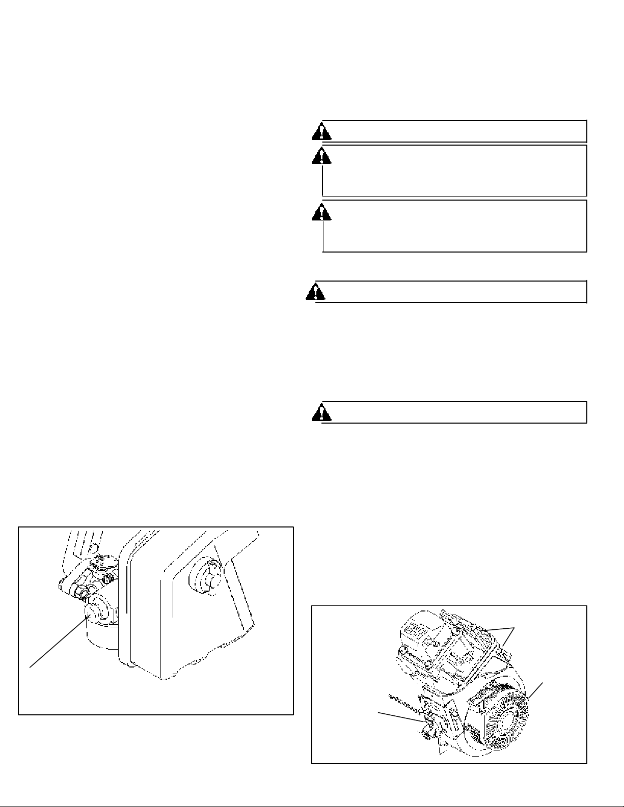
ÂÂ COOLING SYSTEM (see Figure 1 and 4):
IMPORTANT: Frequently remove grass clippings, dirt and debris
from cooling fins, air intake screen and levers and linkage. This
will help ensure adequate cooling and correct engine speed.
Figure 4
Page 3 181-1032-14
STARTING (Continued)
ÂÂ ELECTRIC STARTER (with choke):
A. Move choke lever to “FULL CHOKE POSITION.”
NOTE: IF RESTARTING A WARM ENGINE AFTER A SHORT
SHUTDOWN, MOVE CHOKE LEVER TO “NO CHOKE
POSITION.”
B. Move equipment control (see manufacturer’s instructions) or
engine control to “START”.
C.Push starter button or turn ignition switch key (see equipment
manufacturer’s instructions) to crank engine.
D.Crank engine until it fires. When it starts, release starter button
or ignition switch key and move choke lever to “1/2 CHOKE”
until engine runs smoothly and then to “NO CHOKE POSITION.”
If engine falters, move choke lever to “1/2 CHOKE” until engine
runs smoothly and then to “NO CHOKE POSITION.”
NOTE: If engine fires, but does not continue to run, move
choke lever to “NO CHOKE POSITION’’ and crank
engine until it starts.
NOTE: If engine again fires, but does not continue to run,
move choke lever to “FULL CHOKE” and repeat
instructions B, C and D until engine starts.
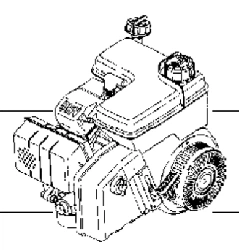
ÃÃ ELECTRIC STARTER (with primer):
A. Move equipment control (see manufacturer's instructions)
or engine control to "START".
B. Push primer two (2) or three (3) times (see Figure 3). Wait
about two (2) seconds between each push. In cold weather
(50
0
F/10
0
C or below) push five (5) times.
NOTE: PRIMER MAY BE NEEDED TO RESTART A WARM
ENGINE AFTER A SHORT SHUTDOWN.
C.Push starter button or turn ignition switch key (see equipment
manufacturer’s instructions) to crank engine.
D.Crank engine until it fires. When it starts, release starter button
or ignition switch key .
NOTE: If engine does not start after about (5) seconds of
cranking, stop cranking, push primer two (2) times
and crank engine again.
Figure 3
PRIMER BUTTON
LEVERS AND
LINKAGE
COOLING FINS
RECOIL
COVER
NOTE: RECOIL COVER CUTAWAY TO SHOW COOLING FINS
Loading ...
Loading ...
Loading ...