ELECTRIC BIKE
ALPINE

Contents
Congratulationson your purchase ........................................................
Warning Message .................................................................... ..... ..... ...
Unpacking and Product Specs ...............................................................
Get To Know Your E-Bike ........................................................................
Handlebar Installation ............................................................................
Saddle Installation ...................................................................................
Front Wheel Installation .........................................................................
Front mudguard, headlight installation ...............................................
Function Denition ..................................................................................
Battery Removal ......................................................................................
Battery Charging .....................................................................................
Optional Accessories Installation ..........................................................
Tire Ination Instructions .......................................................................
User Maintenance Instructions ............................................................
Charge Your E-Bike ..................................................................................
Don’t Ride Until You Read This ..............................................................
01
03
08
09
10
11
Pedal Installation ....................................................................................
12
13
14
15
16
18
Front Rack Installation ............................................................................
17
20
22
25
26
Battery Information ................................................................................
32
Precautions For Battery Protection ......................................................
33
Fault Code ................................................................................................
Warranty .................................................................................................
34
35
02
01
Congratulations
on your purchase!
This user manual will help you assemble
and operate your new electric bicycle. Be
sure to read ALL OF THE INFORMATION in
this manual before riding.
NOTE TO ALL RIDERS UNDER THE AGE OF 18:
It’s very important that you get parental
permission before riding your electric
bicycle.
TOOLS INCLUDED: 3mm,4mm,5mm,6mm Allen
wrenches,one each;13-15mm open-end rench;Phillips
and athead combination screwdriver.
02
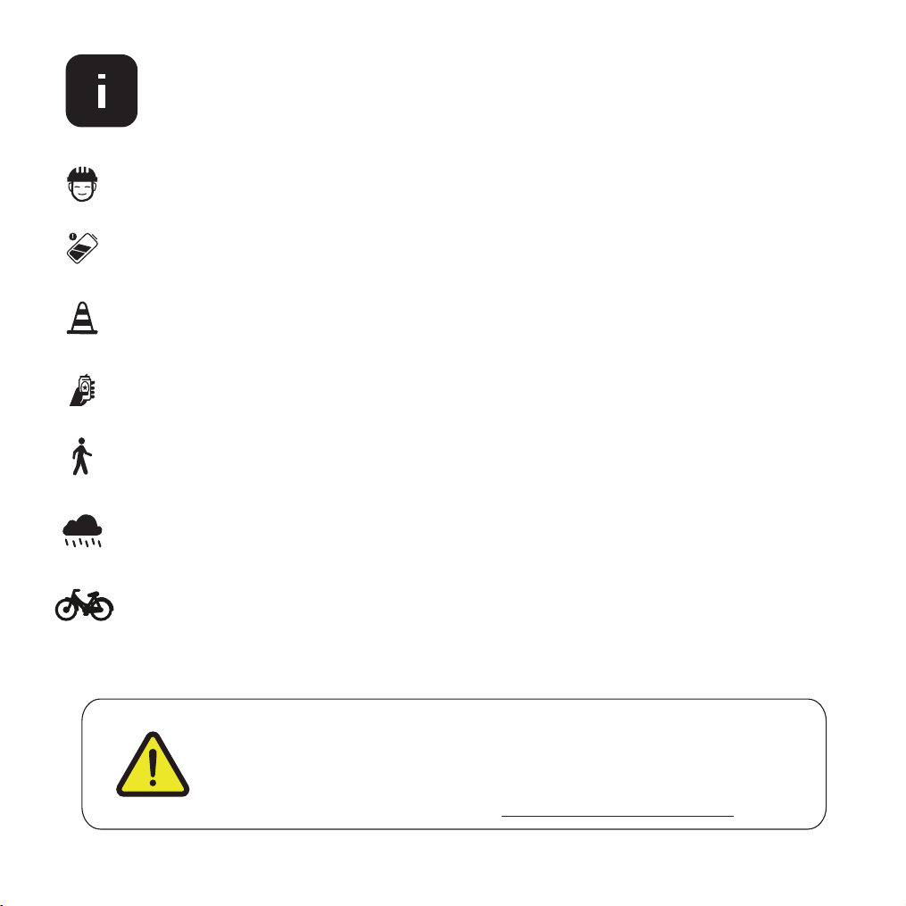
ALWAYS wear a helmet when riding your electric bike.
Make sure your electric bike has a full battery before taking it out to ride.
Always be aware of local road laws, and follow them.
Do not
Always respect pedestrians.
Do not ride under wet conditions. The electric bike may slide from under your
feet causing injury. Wet conditions may damage the electronics and void the
To conserve electricity, use assist mode and avoid zero starting, frequent braking,
driving against the wind, carrying heavy loads including other people and riding
with insucient air pressure.
warranty.
ride the bike under the inuence of drugs or alcohol.
Don’t Ride Until You Read This:
WARNING: Lithium-ion Batteries and/or products that contain
Lithium-ion Batteries can expose you to chemicals including cobalt
lithium nickel oxide, and nickel, which are known to the State of
California to cause cancer and birth defects or other reproductive
harm. For more information, go to www.P65Warnings.ca.gov

03
Warning Message
1. Avoid water - The electric bike is not waterproof. The electronics may be damaged
due to water and water damage is not covered by our warranty. Riding in wet
conditions is also very dangerous and may result in injury.
2. Avoid prolonged exposure to sun or rain and avoid storage in places with high
temperatures or corrosive gas.
4.
5.
6.
Do not modify the product from the manufacturers original design.
7.
Do not exceed
8.
Avoid touching the charging port directly and do not let it make contact with a
metal object.
9.
Keep hands and all body parts away
from moving parts while operating the
electric bike.
10.
Before riding - be sure to check the electric bike over and make sure all components
and function are operating correctly before each use.
11.
Before riding - be sure
to check that t
he braking system is functioning properly;
also be sure to check that all safety labels are in place and you understand the
safety warnings.
12.
Before riding - be sure that any and all axle guards, chain guards, or other covers
be sure to check that the tires are in good condition, inated properly,
and have sucent tread remaining.
or guards supplied by the manufacturer are in place and in serviceable condition.
Before riding -
the posted speed limit and obey all trac laws.
Whenever you ride the GOTRAX Electric Bike ,you risk severe injury or even death
from loss of control, collisions, and falls. Use caution and ride at your own risk.
3.
Abuse - We do not cover physical damage due to negligent care and extreme riding.
13. Never exceed the 330lbs (150 kg) maximum load rating.
14. The electric bike should never be used by children under the age of 16.
15. Maximum Speed - Your electric bike accelerates to a maximum speed of 25 mph.
04
16. Make note that additional insurance may be required to cover situations you
encounter while riding an electric bike. It is recommended that you contact an
insurance company or broker for advice and consultation.
17. To conserve electricity, use assist mode and avoid zero starting, frequent braking,
driving against the wind, carrying heavy loads including other people and riding with
insucient air pressure.
05
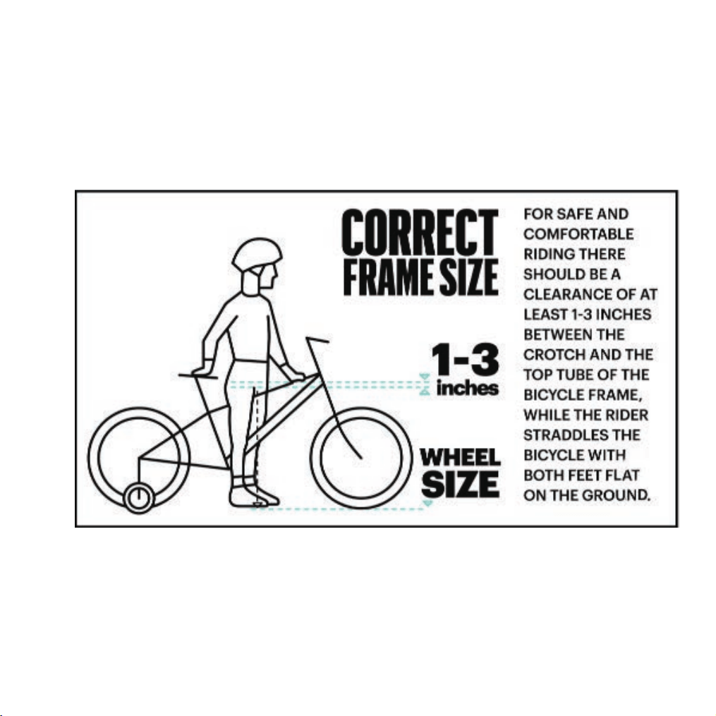
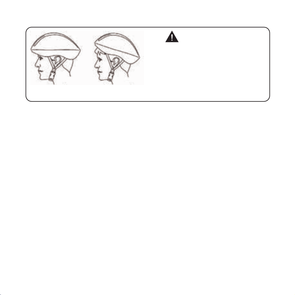
Correct
Forehead covered
Incorrect
ALWAYS WEAR A HELMETIT
COULD SAVE YOUR LIFE!
A properly tting, CPSC approved, bicycle helmet
should be worn at all times when riding your bicycle.
In addition, if you are carrying a passenger (only use
an approved child safety seat), and remember, the
passenger must also be wearing a helmet.
The correct helmet should:
-be comfortable
-be lightweight
-have good ventilation
-t correnctly
-cover the forehead
-be securely fastened on the rider.
Forehead exposed
FCC REGULATIONS This device complies with Part 15 of the FCC Rules. Operation
is subject to the following two conditions: (1) this device may not cause harmful
interference, and (2) this device must accept any interference received, including
interference that may cause undesired operation.
Caution: The user is cautioned that changes or modications not expressly approved
by the party responsible for compliance could void the user's authority to operate
the equipment.
Note: This equipment has been tested and found to comply with the limits for a Class
B digital device, pursuant to part 15 of the FCC Rules. These limits are designed to
provide reasonable protection against harmful interference in a residential installation.
This equipment generates, uses and can radiate radio frequency energy and, if not
installed and used in accordance with the instructions, may cause harmful interference
to radio communications. However, there is no guarantee that interference will not
occur in a particular installation. If this equipment does cause harmful interference to
radio or television reception, which can be determined by turning the equipment o
and on, the user is encouraged to try to correct the interference by one or more of the

06
following measures:
*Reorient or relocate the receiving antenna.
*Increase the separation between the equipment and receiver.
*Connect the equipment into an outlet on a circuit dierent from that to which the
receiver is connected.
*Consult the dealer or an experienced radio/TV technician for help.

07
Prolonged Exposure to UV Rays, Rain and the Elements May Damage the Enclosure
Materials, Store Indoors When Not in Use.
SAVE THESE INSTRUCTIONS
MOVING AND STORAGE INSTRUCTIONS
WARNING - When using this product, basic precautions should always be followed
includingthe following:
a)Read all the instructions before using the product.
b)To reduce the risk of injury, close supervision is necessary when the product is
used nearchildren.
c) Do not put ngers or hands into the product.
d) Do not use this product if the exible power cord or output cable is frayed, has
broken insu-lation, or any other signs of damage.
e)This equipment is not intended to be used at ambient temperatures less than 0°C
(32°F) or above ambient temperatures of 40°C(104F).
f)The battery is intended to be charged when the ambient temperature is between
0°C(32°F)and 40°C(104°F). Never charge the battery when ambient temperatures
are outside this range.
g)lnstructions are indicate that charging of the eBike shall only be performed with
the manufacturer's recommended charger.
IMPORTANT SAFETY INSTRUCTIONS
Leave it indoor when charging or not riding.
WARNING - Risk of Fire - No User Serviceable Parts.
Not intended for use at elevations greater than 2000 m above sea level.
08
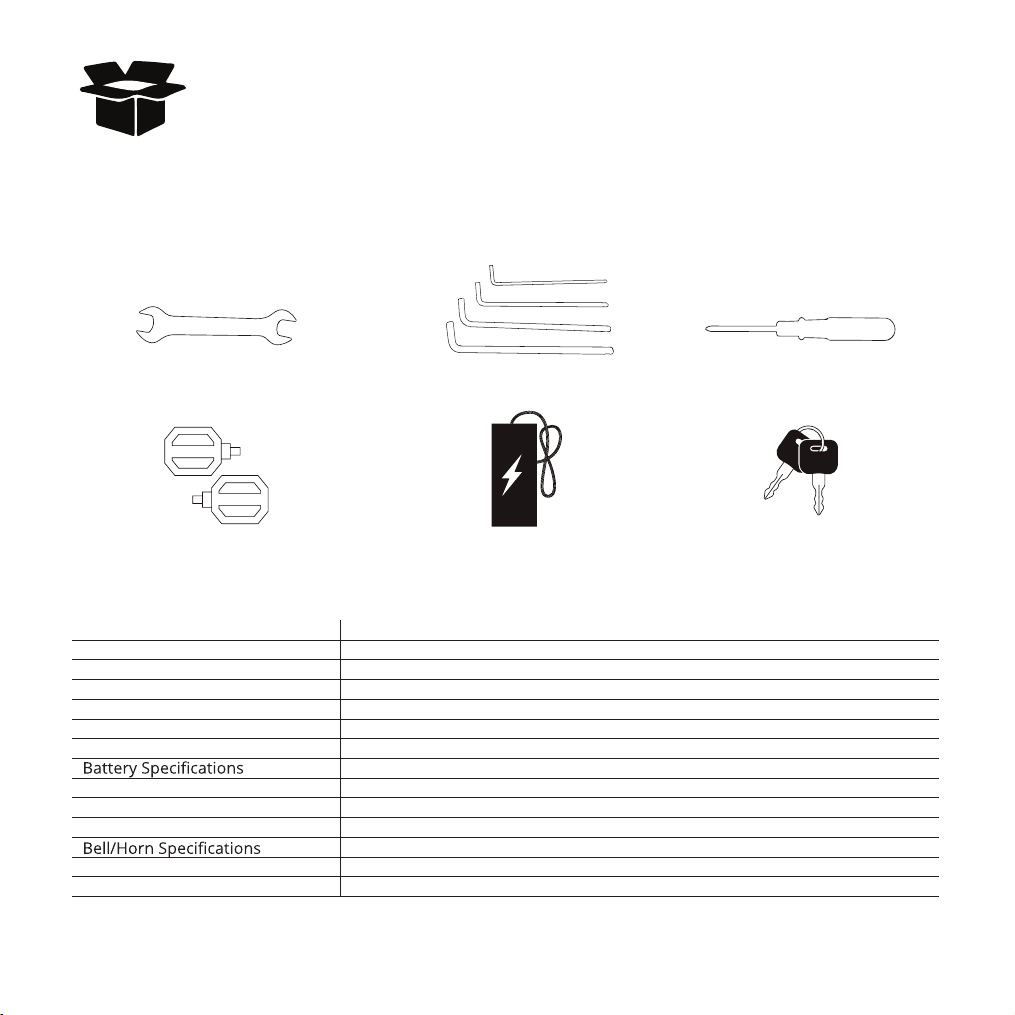
Remove all packaging material, then inspect each item for any accidental damage
your box: that may have occurred during shipping. You should nd each of item
in you box:
Unpacking and Product Specs
Pedal Battery Charger Battery Keys
Large wrench Allen wrenches Screwdriver
ITEM SPECIFICATIONS
Model
ALPINE
Unfolded Dimensions
1910*700*1190mm
Package Dimensions 1510*385*860mm
Max Load Weight 150KG(330Ibs)
Max Speed 25mph
Battery 48Vdc 13.5Ah
Max Angle of Climb 15 degrees
Charging Time 7 hours
Tire Pressure 20P.S.I
Input 100-240V 50/60Hz AC Plug; Output 54.6Vdc 2A
Bell
Seat 6061 Aluminum Alloy
IP Level IPX4
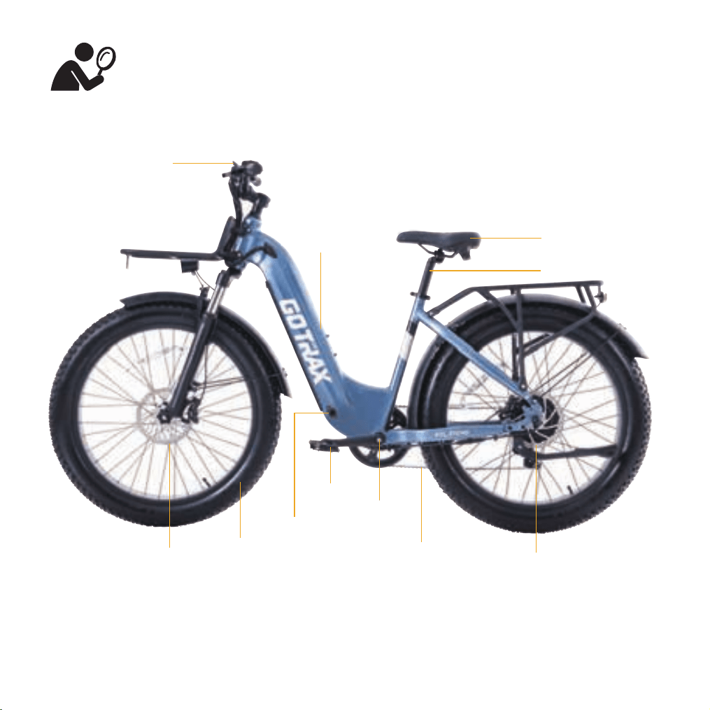
Get To Know Your E-Bike
LED Display
Saddle
Seat Post
Battery
Pedals
Motor
Disc Brake
Wheel Chain
Tire
Crankset
Charger Port
09
1
6
2
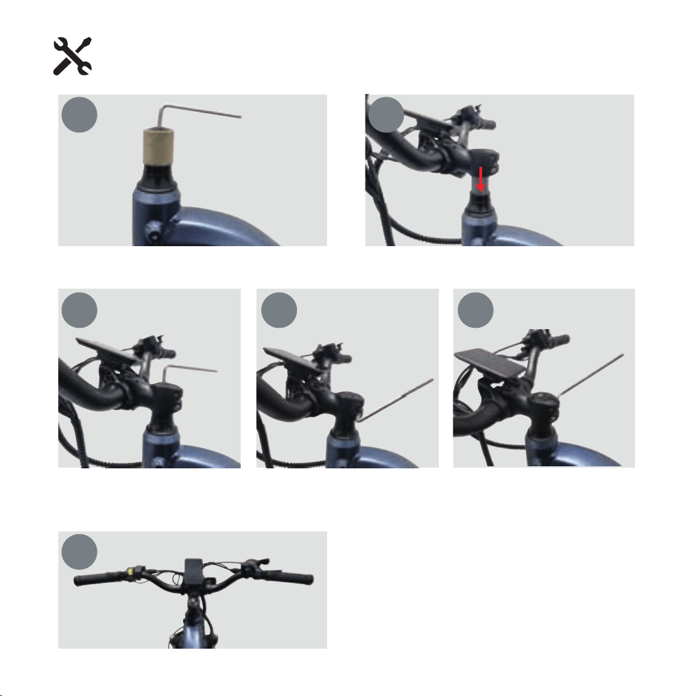
Finally, ensure the handlebar steerer tube is
centered. If not, repeat the above adjustments,
and then place the top cap plug on the top
bolt.
Use a 5mm hex key to turn counterclockwise to remove the stem cap, then insert the steerer tube into
the frame's head tube.
Handlebar Installation
10
After adjusting the handlebar to the desired angle, use the top cap and bolt removed in step one, and
tighten the steerer tube top cap rst with a 5mm hex key by turning clockwise, then tighten the bolts on
both ends of the handlebar.
3 4 5
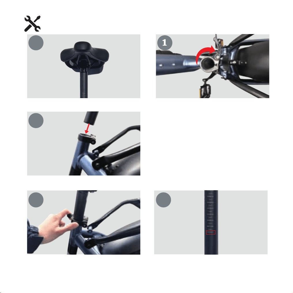
Find the cushion and seat post.
Open the seat clamp quick release;
1
Insert seat tube and adjust position
Finally, close the seat clamp quick release and ensure the seat post cannot move or rotate after locking
(insert up to the minimum insertion mark, check if the saddle is centered).
3
4 5
Saddle Installation
11
1
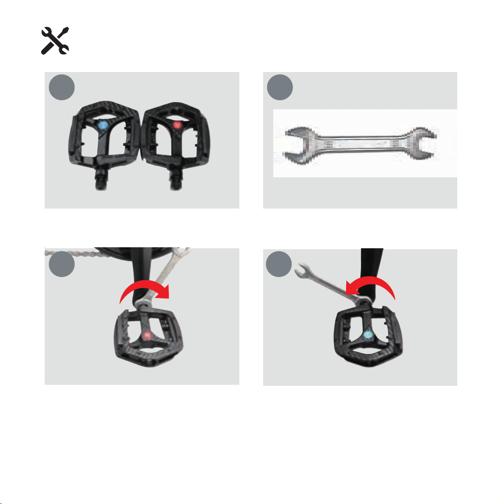
Please check the L and R marked pedals.
Install the right pedal marked with R on
the right side and tighten it clockwise with
the 15mm wrench.
Install the left pedal marked with L on the left
side and tighten it counterclockwise with the
15mm wrench.
Take a 15mm open-end wrench from the
toolbox.
2
3 4
1
Pedal Installation
12
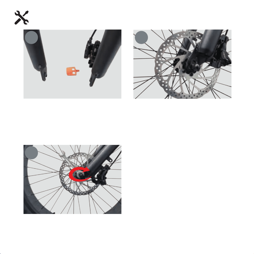
Remove the plastic inserts from inside
the disc brake calipers (note: the inserts
need to be inserted back into the disc
brake calipers whenever the front wheel
is removed)
Lock the nuts on both sides of the front
axle with a 15mm open end wrench
Remove the protective cover from the front
wheel axle, align the front disc brake pad
duck with the disc brake rim gap, and then
slowly install the wheel onto the fork (note:
the spacers on both sides of the front wheel
axle need to be on the outside of the hook
and jaw)
Front Wheel Installation
1 2
3
13
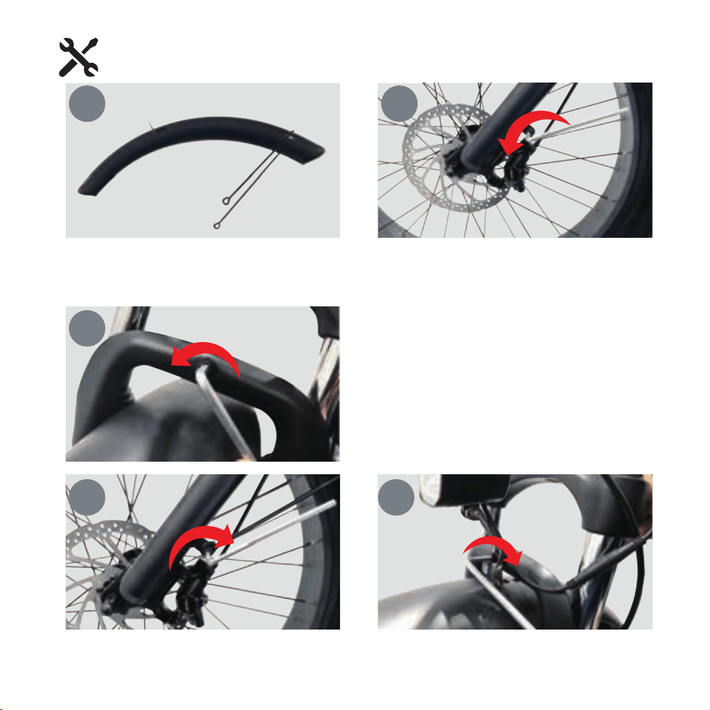
Find the front mudguard in the packaging
box
Use a 4mm hex key to turn counterclockwise
to remove the screws from the fork
mudguard xing plate (one on each side).
1
Use a 5mm Allen wrench to unscrew
the screws on the front fork shoulder
counterclockwise.
Use a 4mm and 5mm Allen wrench to rotate clockwise to x the front mudguard bracket on the front fork
(Note: Adjust the mudguard and tire spacing, and install the front mudguard together with the front light).
3
4 5
Front mudguard, headlight installation
14
2
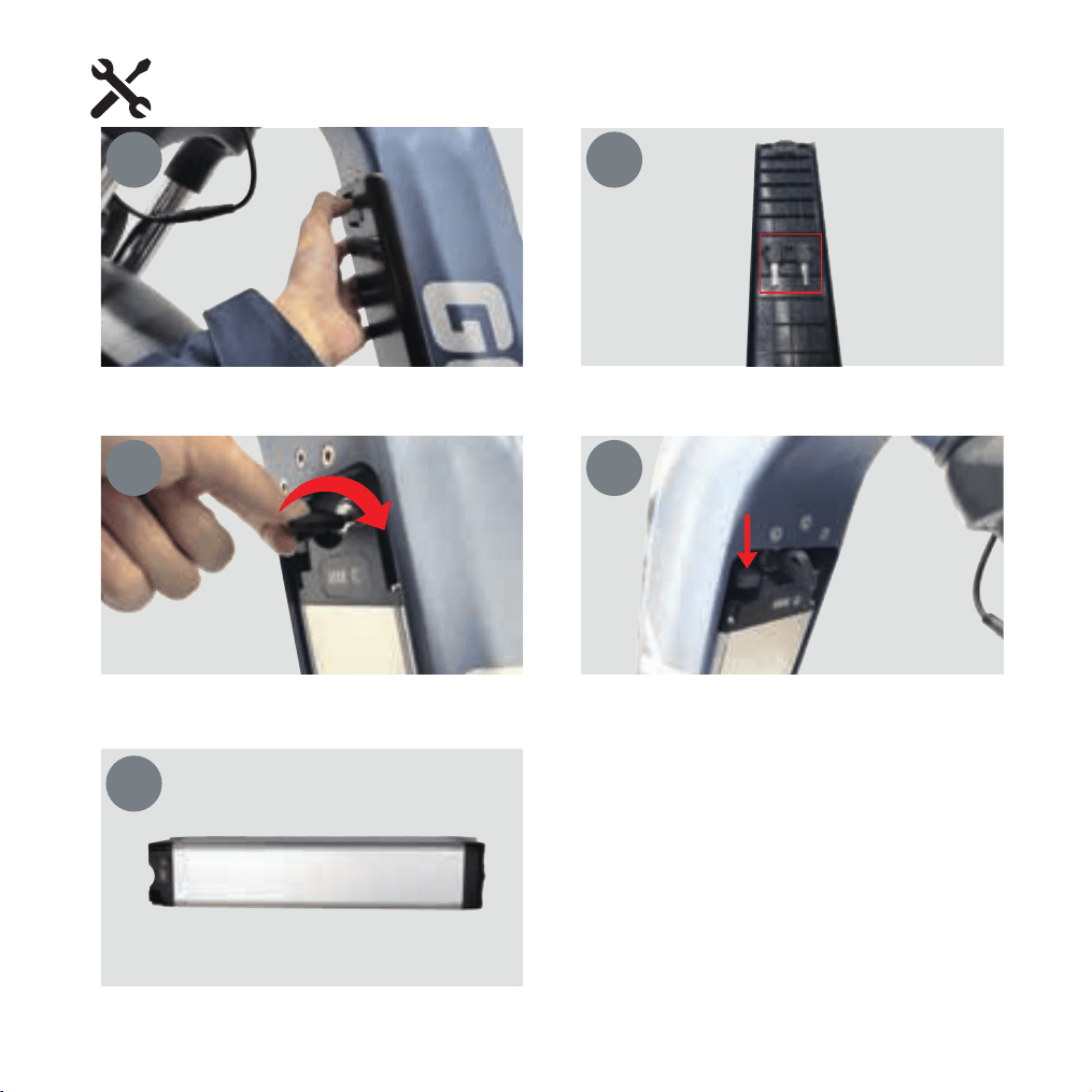
Slide down the battery cover plate, remove the cover plate, and take out the key from the back of the
battery cover.
1
5
Battery Remova
15
2
After removing the battery, you can carry the
battery to charge it separately, and it is
especially important to store the battery when
it is not in use
Insert the removed key into the keyhole, turn the key clockwise to unlock the battery, then press
down the second lock on the battery to remove it.
3 4
16
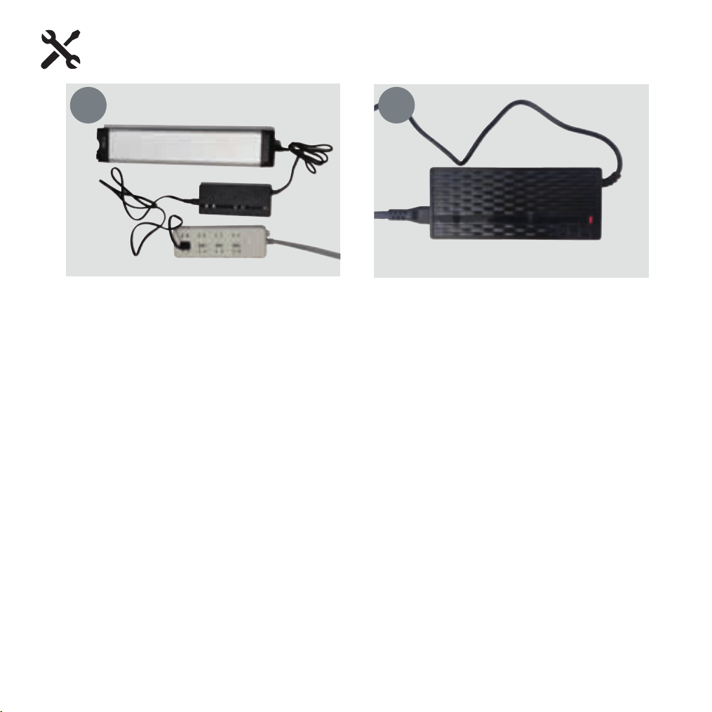
Insert the output of the charger into the battery
and the input into the power supply
Red light indicates that the battery is currently
charging, green light indicates that the battery
is fully charged
Battery Charging
1 2
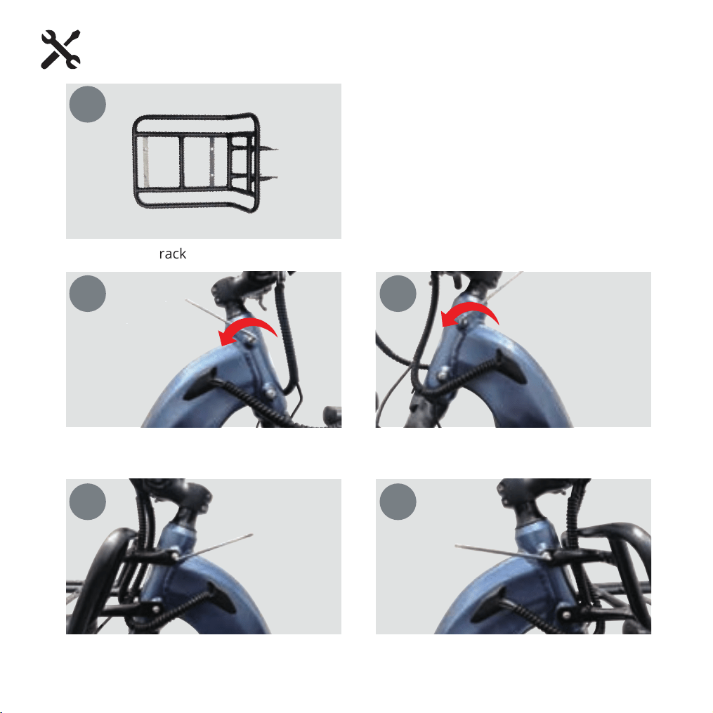
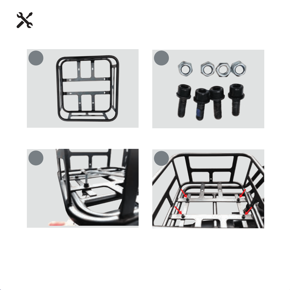
Find the front rack in the box
Front Rack Installation
1
17
Using a 4mm Allen wrench turned counterclockwise, remove the front rack Installation screws on the
left and right sides of the head tube respectively (four in total)
Use a 4mm allen wrench to install the front rack on the head tube by turning clockwise
2 3
4 5
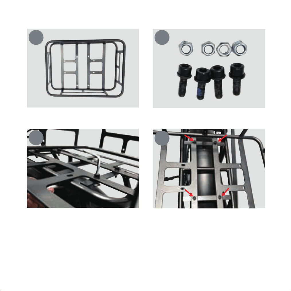
Locate the front grocery basket and 4pc Installation screws and nuts
Front Basket Installatio
Optional Accessories Installation
1 2
After aligning the installation holes of the front basket and the front rack, insert the screws, tighten the
nuts, and use a 5mm hex key and 10mm open-end wrench to turn clockwise to lock the screws.
3
4
18
19
Find the rear basket and 4pc xing screws and nuts.
Rear Basket Installation
1 2
After aligning the installation holes of the rear basket and the rear rack, insert the screws, tighten the
nuts, and use a 5mm hex key and 10mm open-end wrench to turn clockwise to lock the screws.
3
4

Tire Inflation Instructions
After assembling your bike, it will be necessary to inate the tires. Check the sidewall of
the tire for the correct tire pressure (PSI) and inate tires accordingly with a MANUAL
BICYCLE PUMP. Improper inflation is the biggest cause of tire failure. Due to the
slightly porous nature of bicycle inner tubes, it is normal for your bike tires to
lose pressure over time. For this reason it is critically important to maintain the
proper tire inflation on your bike.
1. Your bicycle has been equipped with tires which the bike’s manufacturer felt were
the best balance of performance and value for the use for which the bike was intended.
The tire size and pressure rating are marked on the sidewall of the tire. CAUTION: Pencil
type automtive tire gauges and gas station air hose pressure settings can be inaccutate
and should not be relied upon for consistent, accurate pressure readings. Instead, use a
high quality dial gauge.
WARNING: NEVER INFLATE A TIRE BEYOND THE MAXIMUM PRESSURE
MARKED ON THE TIRE’S SIDEWALL. EXCEEDING THE RECOMMENDED
MAXIMUM PRESSURE MAY BLOW THE TIRE OFF THE RIM, WHICH COULD CAUSE
DAMAGE TO THE BIKE AND INJURY TO THE RIDER AND OTHERS. THE BEST WAY
TO INFLATE A BICYCLE TIRE TO THE CORRECT PRESSURE IS WITH A BICYCLE
PUMP. NEVER USE A SERVICE STATION AIR HOSE TO INFLATE A BICYCLE TIRE. IT
IS DESIGNED FOR LARGER TIRES AND IT CAN EXCEED THE RECOMMENDED
MAXIMUM PRESSURE AND IT MAY BLOW THE TIRE OFF THE RIM.
Tires and Tubes
20
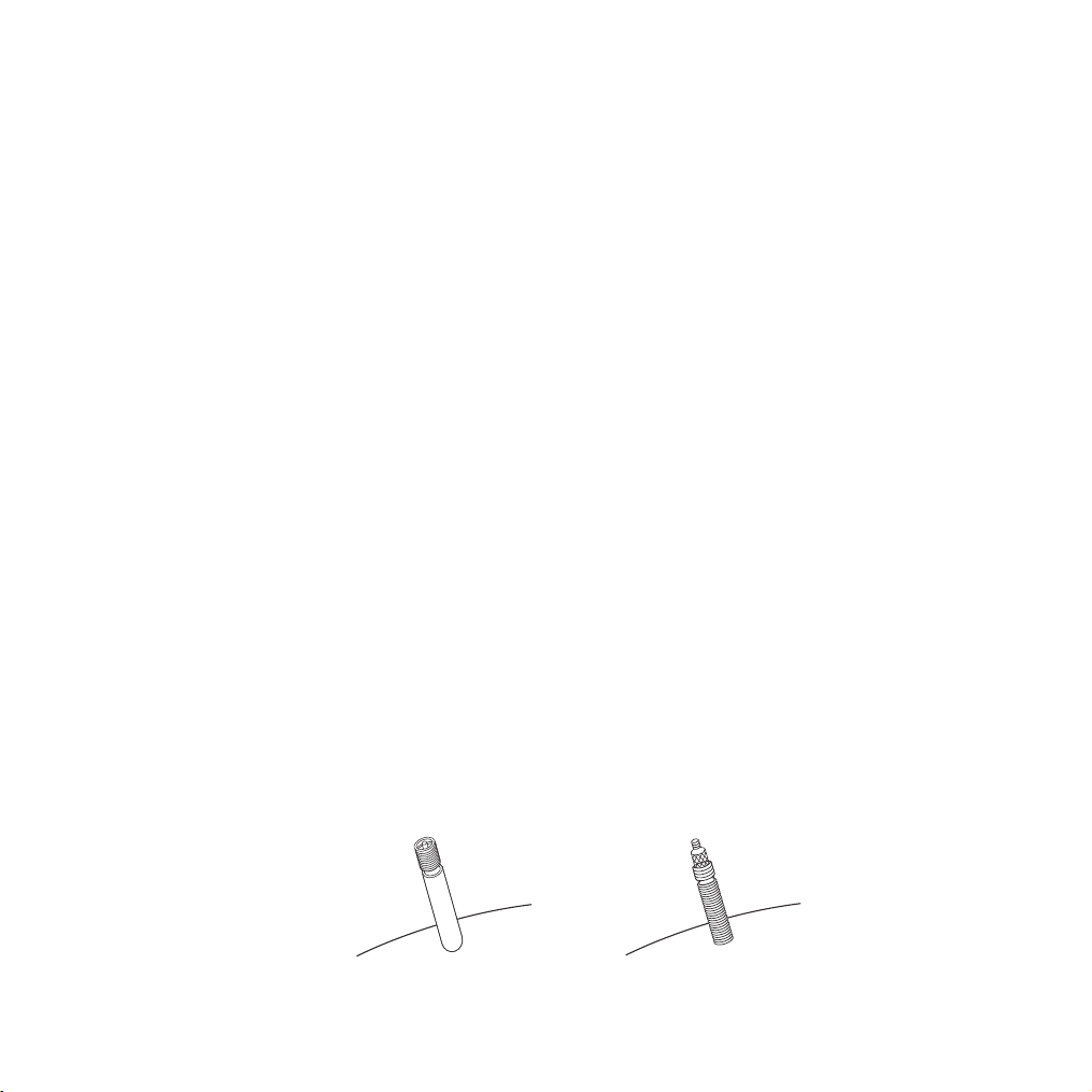
Schraeder Valve Presta Valve
Tire pressure is given either as maximum pressure or as a pressure range. How a tire
performs under dierent terrain or weather conditions depends largely on tire
pressure. Ination the tire to near its maximum recommended pressure gives the
lowest rolling resistance; but also produces the harshest ride. High pressures work
best on smooth, dry pavement. Very low pressures, at the bottom of the
recommmended pressure range, give the best performance on smooth, slick terrain
such as hard-packed clay, and on deep, loose surfaces such as deep, dry sand. Tire
pressure that is too low for your weight and the riding conditions can cause a
puncture of the tube by allowing the tire to deform suciently to pinch the inner tube
between the rim and the riding surface.
Some special high-performance tires have unidirectional treads: their tread pattern is
designed to work better in one direction than in the other. The sidewall marking of a
unidirectional tire will have an arrow showing the correct rotation direction. If your
bike has unidirectional tires, be sure that they are mounted to rotate in the correct
direction.
2. The tire valve allows air to enter the tire’s inner tube under pressure, but doesn’t let
it back out unless you want it to. There are primarily two kinds of bicycle tube valves:
The Schraeder Valve and the Presta Valve. The bicycle pump you use must have the
tting appropriate to the valve stems on your bicycle. The Schraeder is like the valve
on a car tire, this is the type of valve stem you should have on your bike. To inate a
Schraeder valve tube, remove the valve cap and push the air hose on you bike. To
inate a Schraeder valve tube, remove the valve cap and push the air hose or pump
tting onto the end of the valve stem. To let air out of a Schraeder valve, depress the
pin on the end of the valve stem with the end of a key or other appropriate object.
21

22
User Maintenance Instructions
Correct routine maintenance of your new bike will ensure a longer life
for your bike and a safer ride for you.
Every time you ride your bike, its condition changes. The more you ride, the more
frequently maintenance will be required. We recommend you spend a little time on
regular maintenance tasks. The following schedules will assist you in knowing what
tasks need to be performed and how often. If you have any doubts about your
abilities to accomplish these tasks, we recommend you task youe bike to a
professional bicycle mechanic periodically to have them done.
Schedule1 - Lubrication
Frequency
Weekly
Monthly
Every Six Months
Yearly
chain
derailleur wheels
derailleurs
brake calipers
brake levers
bottom braket
pedals
derailleur cables
wheel bearings
headset
seat pillar
shift levers
shift levers
brake cables
chain lube or light oil
chain lube or light oil
oil
oil
oil
lithium based grease
lithium based grease
lithium based grease
lithium based grease
lithium based grease
lithium based grease
lithium based grease
oil
lithium based grease
brush on or squirt
brush on or squirt
oil can
3 drops from oil can
2 drops from oil can
bicycle mechanic
disassemble
disassemble
bicycle mechanic
bicycle mechanic
disassemble
disassemble
2 drops from oil can
disassemble
Component Lubricant How to Lubricate

23
Note: The frequency of maintenance should increase with use in wet or dusty
conditions. Do not over lubricate-remove excess bubricant to prevent dirt
build up. Never use a degreaser to lubricate your chain (WD-40T™)
Schedule2 - Service Checklist
NOTE: Many instructions for adjustments can be found in the assembly portion
of this manual.
Frequency Task
Before every ride
After every ride
Weely
Monthly
check wheel and pedal tightness
check tire pressure
check brake operation
check wheels for loose spokes, loose axle nuts or quick release
make sure all fasteners are tightened securely
lubrication as per schedule 1
check derailleur adjustment
check brake adjustment
check brake and gear cable adjustment
check tire wear and pressure
check wheels are true and spokes tight
check hub, head set and crank bearings for looseness
quick wipe down with damp cloth
lubrication as per schedule 1
check pedals are tight
check handlebars are tight
check seat and seat post are tight and comfortably adjusted
check frame and fork for trueness

24
Every six months
Yearly
lubrication as per schedule 1
check all points as per monthly service
check and replace brake pads, if required
check chain for excess paly or wear
lubrication as per schedule 1
NOTE: OWNERS ARE RESPONSIBLE FOR ALL MAINTENANCE AND SERVICE OF
THE BICYCLE. FAILURE TO DO SO MAY VOID YOUR WARRANTY, CAUSE DAMAGE
TO YOUR BIKE OR ITS COMPONENTS, AND MAY CAUSE AN ACCIDENT.
check all nuts and bolts are tight
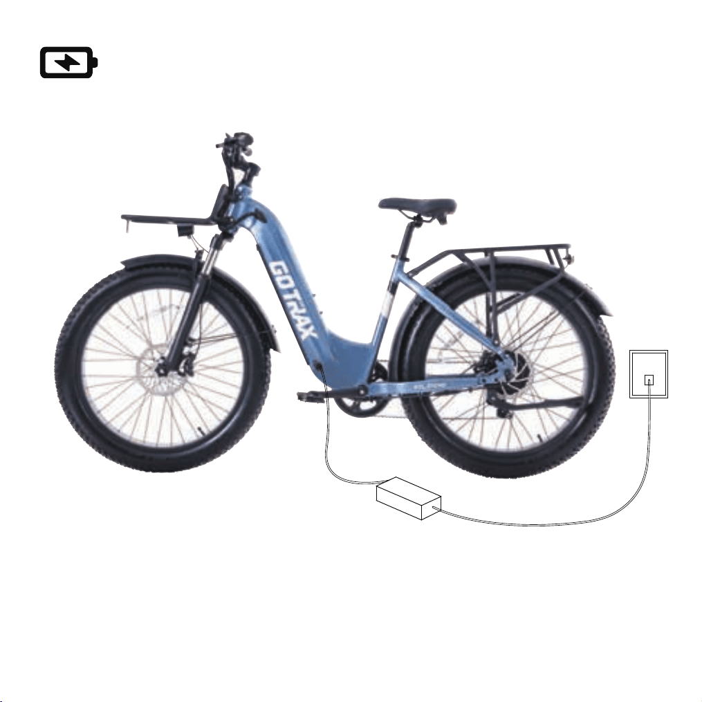
You can also charge your battery installed in the bike using the exterior charging port.
1. Locate the charging port.
2. Plug one side of the charger into the charging port and plug the other into an outlet.
3. A red light indicates the battery is charging, green indicates the battery is full.
4. Charging Time: 7 hours.
Charge Your E-Bike
25
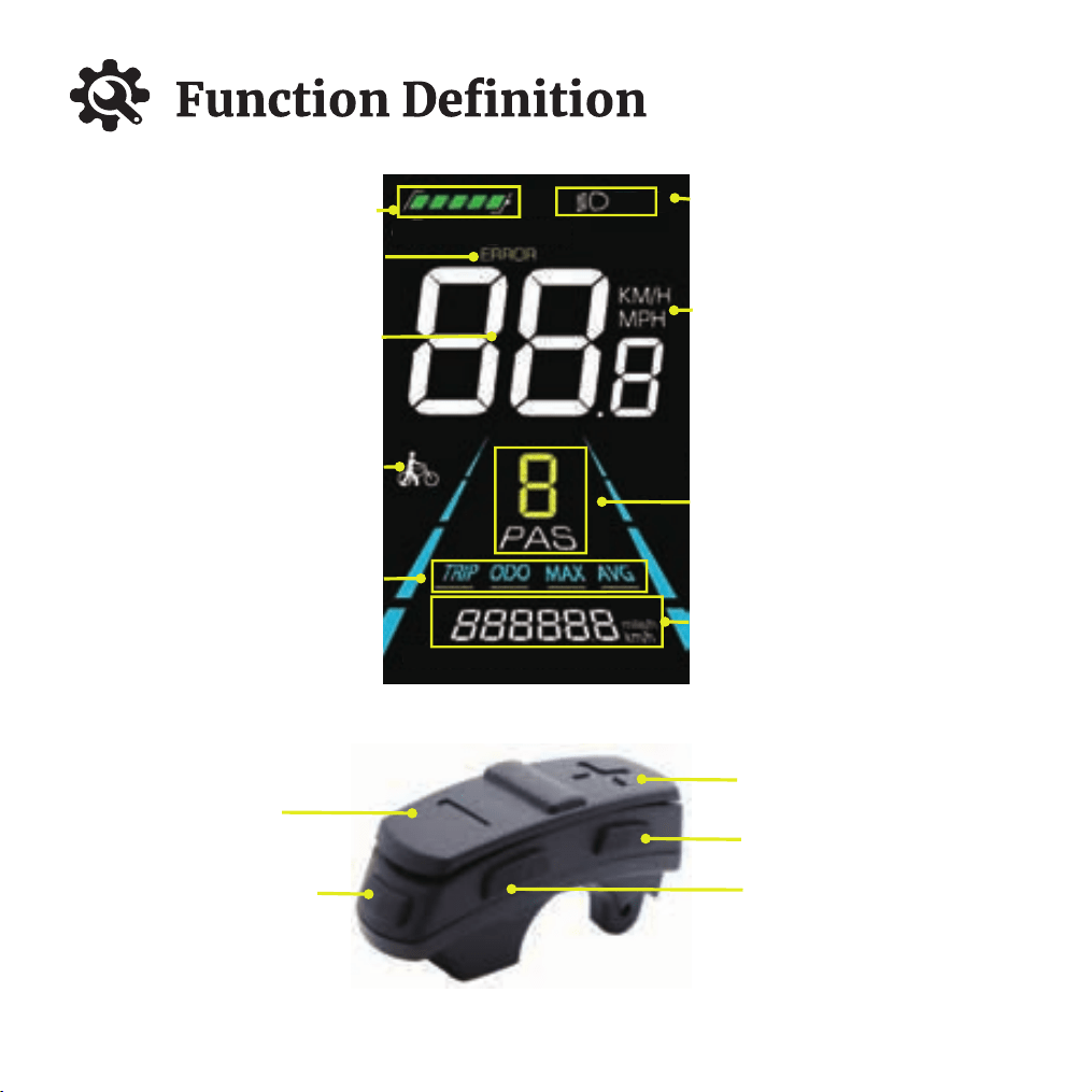
Battery level display
Headlight Icon
Speed Unit Display
Gear Display
Minus Button
Power On/Off Button
Plus Button
Confirm "i" Button
Headlight Button
Range and Unit Display
Fault Indication
Real-time Speed
Power Assist Push Icon
Single Trip Mileage
Total Travel Distance
Maximum Speed
Average Speed
26
27
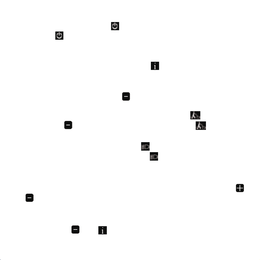
Power On/Off: Press and hold the button for 2-3 seconds to activate the display
and press the button again for 2-3 seconds to turn o the display (the bike will
automatically power o , if there is no activity for 10 minutes in a stationary state).
Turning On/Off Headlights: Shortly press the button to turn on the headlights,
and the display panel backlight will dim. Press the button again to turn o the
headlights, and the display panel backlight will return to its normal brightness.
Display Data Switching: After the display panel is powered on, it defaults to display-
ing real-time, speed and total mileages. Press the button shortly to switch
between total mileage, single trip mileage, max speed, and average speed in the
displayed information.
Power Assist Gear Selection: There are a total of 0-5 gear positions, and the default
on startup is 0, which is a neutral position with no power output. Shortly press the
or button to increase or decrease the gear position. (In power assist mode 1-5,
there are gear distinctions, while in electric mode 1-5, there are no gear distinctions).
Reset single trip mileage: When the speed on the main interface is 0, simultaneously
press and hold the " " and " " keys for more than 2 seconds to reset the single
trip mileage. The main interface will ash once during the clearing process.
Power Assist Pushing: Long press the button, and the electric bike enters the
power assist pushing mode. The electric bike will travel at a constant speed of 6
kilometers per hour. At the same time, the screen will display the power assist
icon. Release the button to exit the power assist mode, and the power assist
icon will go o.

28
Battery Display: In a fully charged state, the battery display shows 5 levels of
charge. As the battery level decreases, the bars are reduced accordingly. When the
border is ashing, it indicates critically low battery and requires immediate charging.
Fault Codes: When there is a malfunction in the electric bike's electronic control
system, the display screen will automatically show "ERROR" along with an error code.
Only when the fault is resolved can you exit the fault display screen. After a fault
occurs, the electric bike will not be able to continue to operate. Please contact the
GOTRAX after-sales team for assistance or seek the help of a professional technician
to diagnose and rectify the issue.
Setting Mode:
1.Simultaneously hold the or button for more than 2 seconds to enter the
personalized parameter selection interface.
2.Shortly press the or button to switch between personalized parameter
settings. Press the button to enter the parameter change mode.
3.Shortly press the or button to select parameters. A long press of for
continuous increase and long press of for continuous decrease.
4.Press the button shortly to save the parameter settings and return to the
personalized parameter selection interface.
5.Long press the button to save the parameter settings and exit the personalized
parameter selection interface.

29
Voltage Setting: "02P" is the option for setting the rated voltage, and you can set
the rated voltage to 24V, 36V, or 48V. The factory default is 48V. Adjusting the voltage
may lead to incorrect battery level display, so it's advisable not to adjust it unless
necessary.
Gear Range Setting: "03P" is the option for setting the range of power assist gears.
The instrument panel oers the choice of power assist gear ranges, including 0-3,
1-3, 0-5, and 1-5. The factory default is 0-5. (0-3/0-5 indicates there is a 0 gear, with 0
gear being a neutral state or park gear, while 1-3/1-5 indicates there is no 0 gear,
meaning there is no neutral or park gear).
Wheel Diameter Setting: "04P" is the option for setting the wheel diameter, and the
available wheel diameter options on the display screen are 16, 18, 20, 22, 24, 26,
700C, and 28 inches. The factory default is 29. Adjusting the wheel diameter can lead
to inaccurate speed and mileage display. Therefore, this setting is locked and not
adjustable.
Metric/Imperial Unit Setting: "01P" is the option for selecting metric or imperial
units. "00" represents metric and "01" represents imperial Use the or button
to make the selection, and press the button shortly to save the parameter
setting and return to the personalized parameter selection interface.

Speed Limit Setting: "05p" is the option for setting the speed limit in power assist
mode, and the adjustable range for the vehicle speed limit is 10 to 40 km/h. The
factory default is 32 km/h, and the maximum limit is 40 km/h. This mode allows you
to adjust the speed limit only for power assist mode, as the electric mode has a
maximum limit of 32 km/h, which is not adjustable.
Power-On Password Setting: "06P" is the option for setting the power-on pass-
word. The power-on password function is disabled by default, and users can enable
it by setting a password.The default password when the display is shipped is "1212,"
but you can change it to another four-digit number.
To enable the power-on password:
In the "06P" interface, press the button shortly to enter the parameter change
mode. Use the or button to select "PSd-y" to enable the power-on password.
Then, long press the button to save and exit. The password function is now
enabled successfully.
To disable the password:
In the "06P" interface, press the button shortly to enter the parameter change
mode.Use the or button to select "PSd-n" to disable the power-on password.
Press the button to conrm and exit to the personalized settings selection
interface. Then, either long press the button to return to the main interface or
directly long-press the button to exit to the main interface. The password func-
tion is now successfully disabled.
30

To change the password:
In the "06P" interface, press the button shortly to enter the parameter change
mode.Use the or button to select "PSd-y" to enable password change.Press
the button to conrm and enter the four-digit password setting mode.In the
password setting interface, input your new password. Use the or button to
select the digits and press the button to save each digit and move to the next.
Set all four digits this way.When the lat digit is ashing, long press the button to
save the new password and exit the parameter setting interface. The password is
now changed, and it will take eect upon reboot.
Please remember the new password you set, as you will need it each time you power
on and change the password.
31

Before using the charger locate the voltage selector switch (li-ion chargers only) on the
back of the charger. Select either 115 volts or 230 volts depending on your country of
residence. Using the wrong voltage setting will permanenty damage the charger
and/or electrical components on the hybrid electric bicycle.
BATTERY ASSEMBLY
1. Use the matching charger.
2. Insert the round plug into the E-Bike rst and then insert the charger plug into the
electrical socket.
3. A red light indicates the battery is charging.
4. A green light indicates the battery is fully charged.
5. The Key lock position will vary from model to model.
6. The battery is removable, the battery can be charged attached to the E-Bike or
pulled out and charged separately.
CHARGING THE BATTERY
1. When using the charger for the rst time, carefully check whether the rated output
voltage of the charger is consistent with the battery voltage and check whether the
charger input voltage is consistent with the grid voltage.
2. When charging, rst put the charger in a ventilated place, then insert the charger
output plug into the charging port. Plug the electrical power plug into the 100-240V
50/60Hz AC Power Supply. Be sure to keep the input plug in contact with the AC
outlet.
3. After charging, the input plug of the charger shall be pulled out rst, and then the
output plug connected with E-Bike shall be pulled out. Do not leave the charge
plugged in.
Battery Information
32

1. Do not place anything on the battery and charger when charging, otherwise the
charger may overheat and cause serious damage.
2. Only use the charger supplied by the original factory to charge the battery, if you
use a dierent charger your battery will be disqualied from warranty.
3. You can charge your battery at any time if the battery loses power.
4. If you do not use or charge your battery for an extended period of time, battery
performance will decrease. If you do not plan to ride your bike for an extended period
of time it is recommended to plug in and charge the battery Insert Care/Maintenance
section an extended period every 4-6 weeks.
5. Protection can make your battery maintain about 80% of its capacity after more than
500 cycles. But overall decline is inevitable.
6. If the battery remains in a status not charged a long time, it will lead to permanent
loss of performance.
7. If you want to store your battery for an extended period, please store and discharge it
in a cool and dry place.
8. Keep the temperature between 50-70℉ and avoid direct sunlight. Take the battery
out for charging every 30 days.
9. Do not intentionally short-circuit the battery which will cause very serious damage
and void the warranty.
10. Dispose of your batteries responsibly. Research local recycling regulations.
11. If you have questions about battery use, maintenance, or storage, please contact
customer service.
12. Only use the battery supplied with this electronic bike.
13. Never charge a lithium battery unsupervised.
Precautions For Battery Protection
33

The display
communication faulire
Check if the connection cable between
the display and the controller is
abnormal, and replace the display if
there is no abnormality .
Fault code Code Meaning Troubleshooting solutions
E21
Current Anomaly
Inspect the accelerator connection cable;
if there is no issue with the connection,
replace the accelerator.
E22
Throttle Fault
Inspect the motor connection cable; if
there is no issue with the connection,
replace the motor.
E23
Motor Fault
Inspect the motor connection cable; if
there is no issue with the connection,
replace the motor.
E24
Motor Fault
Inspect the motor connection cable; if
there is no issue with the connection,
replace the motor.
E25
Brake Anomaly
Inspect the brake connection cable; if
there is no issue with the connection,
replace the brake lever.
E30
Fault Code
34

Warranty
Please contact our customer service team if you are experiencing problems or need
more detailed information.
US team after-sales email: [email protected]
CA team after-sales email: [email protected]
1. Users should operate in accordance with the product manual. In case of any
performance fault caused by production quality, the company shall perform
the obligations of the three guarantees in accordance with the provisions of
relevant laws and regulations of the state.
2. The company is still responsible for the after-sales service of the faults
beyond three guarantees and the major components in the three guarantees,
but there will be a cost for repair.
3. If the battery replacement is over the warranty time, our company will supply
the battery at factory pr
ice. To ensure safety, and avoid pollution.
4. We do not cover physical damage due to negligent care and extreme riding.
35


(CA)www.gotraxcanada.com
(US) W W W .G OT R A X . C O M
#RideGOTRAX

(US)GOLABS,INC
GOTRAX.com
2201 Luna Rd.
Carrollton,TX 75006
(CA)Tao Motor Canada Inc.
170 Bartor Road, Unit 1 North York,
Ontario M9M 2W6,
Canada.
