Before attempting to connect or operate this product,
please read these instructions carefully and save this manual for future use.
User's Manual
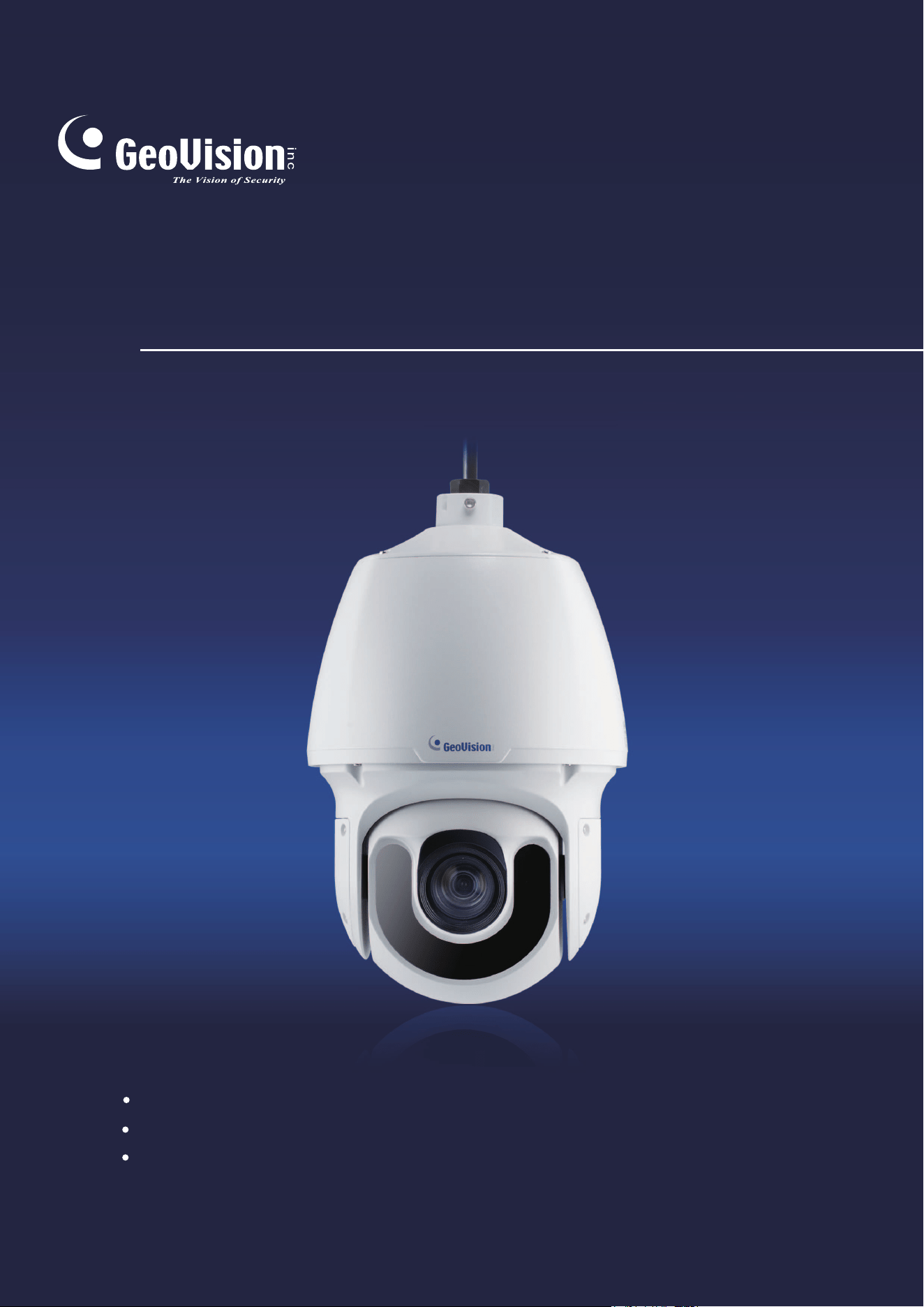
GV-IP Speed Dome
ISD2722IRV101-UM-A
GV-SD2722-IR
GV-SD3732-IR
GV-SD2322-IR

© 2018 GeoVision, Inc. All rights reserved.
Under the copyright laws, this manual may not be copied, in whole or in part,
without the written consent of GeoVision.
Every effort has been made to ensure that the information in this manual is
accurate. GeoVision, Inc. makes no expressed or implied warranty of any kind
and assumes no responsibility for errors or omissions. No liability is assumed
for incidental or consequential damages arising from the use of the information
or products contained herein. Features and specifications are subject to
change without notice.
Note: No memory card slot or local storage function for Argentina.
GeoVision, Inc.
9F, No. 246, Sec. 1, Neihu Rd.,
Neihu District, Taipei, Taiwan
Tel: +886-2-8797-8377
Fax: +886-2-8797-8335
http://www.geovision.com.tw
Trademarks used in this manual: GeoVision, the GeoVision logo and GV
series products are trademarks of GeoVision, Inc.
September 2018
i
Preface
Welcome to the GV-IP Speed Dome User’s Manual.
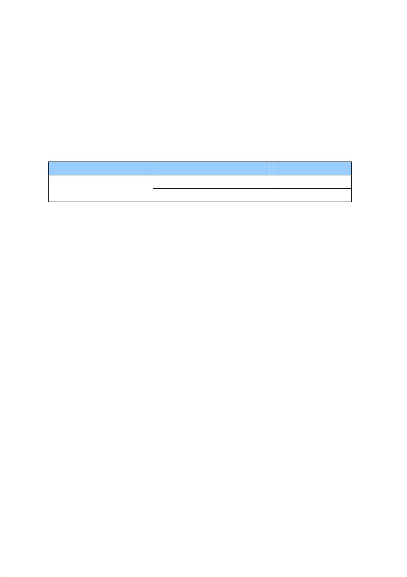
This Manual is designed for the following models and firmware versions:
Model Model Number Firmware Version
GV-SD2322-IR V1.0
IP Speed Dome
GV-SD2722-IR / GV-SD3732-IR V1.01

ii
Contents
Naming Definition.....................................................................v
Note for Connecting to GV-VMS / DVR / NVR .......................vi
Note for Recording .................................................................vii
Note for Installing Camera Outdoor ....................................viii
Chapter 1 Introduction ..........................................................1
1.1 Key Features ......................................................................................................... 2
1.2 Packing List ........................................................................................................... 4
1.3 System Requirements............................................................................................ 5
1.4 Optional Accessories ............................................................................................. 6
1.5 Physical Description............................................................................................... 8
1.6 Accessory Installation (Wall Pendant Mount) ......................................................... 9
1.7 Connecting the Camera ........................................................................................13
Chapter 2 Accessing the Camera.......................................15
2.1 Installing on a Network..........................................................................................15
2.1.1 Checking the Dynamic IP Address............................................................16
2.1.2 Assigning an IP Address...........................................................................17
2.2 Accessing Live View .............................................................................................18
2.2.1 The Live View Window ............................................................................19
Chapter 3 PTZ Control Panel ..............................................23
3.1 Assessing the PTZ Control Panel .........................................................................23
3.1.1 Setting Presets .........................................................................................24
3.1.2 Setting Patrol............................................................................................26
3.2 Setting Home Position ..........................................................................................31
Chapter 4 Administrator Mode ...........................................32
4.1 Common...............................................................................................................35
4.1.1 Navigation / Basic Info.............................................................................35

iii
4.1.2 Local Settings..........................................................................................36
4.2 Network ................................................................................................................38
4.2.1 TCP/IP / Network.........................................................................................38
4.2.2 Port...........................................................................................................40
4.2.3 FTP.........................................................................................................41
4.2.4 E-mail......................................................................................................43
4.2.5 DDNS......................................................................................................45
4.2.6 Port Mapping...........................................................................................47
4.2.7 802.1x .....................................................................................................48
4.3 Video & Audio.......................................................................................................49
4.3.1 Video ........................................................................................................49
4.3.2 Audio ........................................................................................................51
4.3.3 Capture / Snapshot...................................................................................52
4.3.4 ROI...........................................................................................................53
4.3.5 Media Stream ...........................................................................................54
4.4 PTZ.......................................................................................................................56
4.4.1 Home Position ..........................................................................................56
4.4.2 Remote Control.........................................................................................56
4.4.3 Patrol........................................................................................................57
4.5 Image ...................................................................................................................58
4.5.1 Image .......................................................................................................58
4.5.2 OSD..........................................................................................................65
4.5.3 Privacy Mask ...........................................................................................67
4.6 Intelligent ..............................................................................................................68
4.6.1 Recommended Scenario ..........................................................................68
4.6.2 Cross Line ................................................................................................69
4.6.3 Intrusion....................................................................................................70
4.6.4 Auto Tracking ...........................................................................................71
4.6.5 Advanced Settings....................................................................................72
4.7 Events...................................................................................................................73
4.7.1 Motion Detection.......................................................................................73
4.7.2 Tampering Alarm ......................................................................................76
4.7.3 Audio Detection ........................................................................................77
4.7.4 Alarm Input ...............................................................................................79
4.7.5 Alarm Output ............................................................................................80
4.7.6 Capture.....................................................................................................81
4.7.7 Temperature Alarm...................................................................................81
4.8 Storage.................................................................................................................82
4.8.1 Storage.....................................................................................................82

iv
4.8.2 Recording Download ................................................................................84
4.9 Security.................................................................................................................85
4.9.1 User..........................................................................................................85
4.9.2 Network Security.......................................................................................85
4.10 System................................................................................................................87
4.10.1 Time .......................................................................................................87
4.10.2 Maintenance ...........................................................................................89
4.10.3 Security...................................................................................................91
4.10.4 Ports and Device ....................................................................................93
Chapter 5 Recording and Playback ...................................94
5.1 Recording .............................................................................................................94
5.2 Playback from the Memory Card...........................................................................95
Chapter 6 Advanced Applications .....................................97
6.1 Upgrading System Firmware.................................................................................97
6.1.1 Using the Web Interface ...........................................................................98
6.1.2 Using the GV-IP Device Utility ..................................................................99
6.2 Restoring to Factory Default Settings..................................................................100
6.2.1 Using the Web Interface .........................................................................100
6.2.2 Directly on the Camera ...........................................................................101
Chapter 7 VMS / DVR / NVR Configurations....................102
7.1 Setting up IP Cameras on GV-DVR / NVR..........................................................103
7.1.1 Customizing the Basic Settings on GV-DVR / NVR.................................105
7.2 Setting Up IP Cameras on GV-VMS ...................................................................106
Appendix ...............................................................................108
A RTSP Multicast Protocol Support ..........................................................................108
v
Naming Definition
GV-DVR / NVR
GeoVision Analog and Digital Video Recording Software. The
GV-DVR also refers to GV-Multicam System or GV-Hybrid DVR.
GV-VMS
GeoVision Video Management System for IP cameras.

vi
Note for Connecting to GV-VMS / DVR / NVR
The GV-IP Speed Dome is designed to work with and record on GV-VMS / DVR / NVR, a
video management system.
Once the camera is connected to the GV-VMS / DVR / NVR, the resolution set on the GV-
VMS / DVR / NVR will override the resolution set on the camera’s Web interface. You can
only change the resolution settings through the Web interface when the connection to the
GV-VMS / DVR / NVR is interrupted.

vii
Note for Recording
By default, the images are recorded to the memory card inserted in the GV-IP Speed Dome.
Mind the following when using a memory card for recording:
Recorded data on the memory card can be damaged or lost if the data are accessed
while the camera is under physical shock, power interruption, memory card detachment
or when the memory card reaches the end of its lifespan. No guarantee is provided for
such causes.
The stored data can be lost if the memory card is not accessed for a long period of time.
Back up your data periodically if you seldom access the memory card.
Memory cards are expendable and their durability varies according to the conditions of
the installed site and how they are used. Back up your data regularly and replace the
memory card annually.
To avoid power outage, it is highly recommended to apply a battery backup (UPS).
For better performance, it is highly recommended to use Micro SD card or SD card of
MLC NAND flash, Class 10.
Replace the memory card when its read/write speed is lower than 6 MB/s or when the
memory card is frequently undetected by the camera.
viii
Note for Installing Camera Outdoor
When installing the camera outdoor, be sure that:
1. The camera is set up above the junction box to prevent water from entering the camera
along the cables.
2. Any power, audio and I/O cables are waterproofed using waterproof silicon rubber or the
like.
3. The screws are tightened and the cover is in place after opening the camera cover.

1
Chapter 1 Introduction
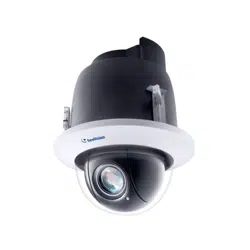
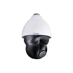
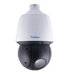
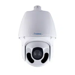
The GV-IP IR Speed Dome is an outdoor network PTZ camera that offers 22x / 33x optical
zoom and unlimited digital zoom, capable of showing smooth live view with great details.
This camera can simultaneously deliver three video streams in resolutions up to 1920 x 1080
at 30 fps (GV-SD2322-IR), 1920 x 1080 at 60 fps (GV-SD2722-IR), or 2048 x 1536 at 30 fps
and 1920 x 1080 at 60 fps (GV-SD3732-IR). In low-light environments, night vision is
enhanced with its high-power LEDs, which allow up to 150 m (492 ft) or 200 m (656 ft,
GV-SD2722-IR) effective IR distance.
Wide surveillance coverage is made possible with 360° endless panning and -15 ~ 195°
tilting capacity. PTZ functions such as Preset, Auto Pan and Patrol can be programmed and
activated by schedule. The GV-IP IR Speed Dome supports pan/tilt speeds ranging from a
fast patrol of 240° per second to a slow ramble of 0.1° per second with 0.1° pan accuracy for
fast and accurate tracking ability.
For GV-SD2722-IR / 3732-IR, with the built-in WDR Pro, it can process scenes with
contrasting intensity of lights and produce clear image. The camera supports H.265 video
codec to achieve better compression ratio while maintaining high quality pictures at reduced
network bandwidths.

2
1.1 Key Features
1/2.8" progressive scan low lux CMOS sensor
1/1.9" progressive scan low lux CMOS sensor (for GV-SD2722-IR only)
Min. illumination at 0.01 lux (B/W) and 0.03 lux (color) (for GV-SD2322-IR)
Min. illumination at 0.03 lux (B/W) and 0.05 lux (color) (for GV-SD3732-IR)
Min. illumination at 0.001 lux (color) (for GV-SD2722-IR)
Triple streams from H.264 and MJEPG (for GV-SD2322-IR only)
Triple streams from H.265, H.264 and MJPEG
Up to 30 fps at 1920 x 1080 (for GV-SD2322-IR)
Up to 60 fps at 1920 x 1080 (for GV-SD2722-IR)
Up to 30 fps at 2048 x 1536, 60 fps at 1920 x 1080 (for GV-SD3732-IR)
22x optical zoom and unlimited digital zoom
33x optical zoom and unlimited digital zoom (for GV-SD3732-IR only)
Intelligent IR
IR distance up to 150 m (492 ft)
IR distance up to 200 m (656 ft) (for GV-SD2722-IR only)
Day and night function (with removable IR-cut filter)
Two sensor inputs and one alarm output
Wide Dynamic Range (WDR) (for GV-SD2322-IR only)
Wide Dynamic Range Pro (WDR Pro)
Vandal resistance (IK10 for metal casing)
Ingress protection (IP66)
Wide temperature tolerance (-40°C ~ 70°C / -40°F ~ 158°F)
Support for TV-out
Two-way audio
Built-in micro SD card slot (SDHC/SDXC, Class 10) for local storage
DC 24V / AC 24V
Pan 360° endlessly
Tilt from -15° to 195°
Pan and tilt speed at up to 300° /s and 240° /s respectively

Introduction
3
1
PTZ movement (Preset, Auto Pan and Patrol)
PTZ patrol by schedule
Smart settings (Cross line, Intrusion, Auto tracking) (for GV-SD2722-IR / SD3732-IR only)
Intelligent Mark (for GV-SD2722-IR / SD3732-IR only)
Auto focus
3D noise reduction
Motion detection
Privacy mask
4
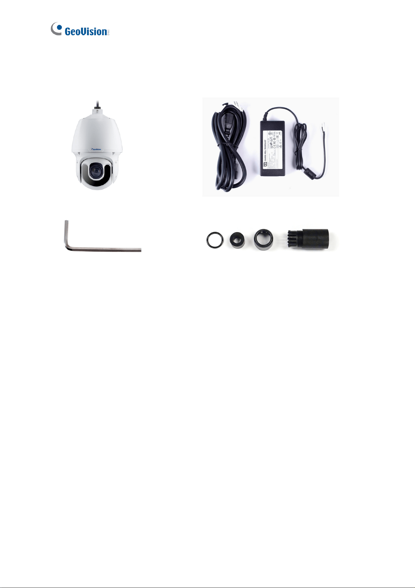
1.2 Packing List
IR IP Speed Dome
24V AC Power Adapter
M4 Hex Key
Waterproof Rubber Set
Waterproof Guidelines
Download Guide
Warranty Card
Introduction
5
1
1.3 System Requirements
CPU Intel Core i5-4670, 3.40 GHz
Memory DDR3 8 GB RAM
On Board Graphics Intel HD Graphics 4600 (Versions of driver from year 2014 or later
required)
Web Browsers Internet Explorer 11.0 or above
Google Chrome
Mozilla Firefox
Safari
Note: Some functions are not available on non-IE browsers.
6
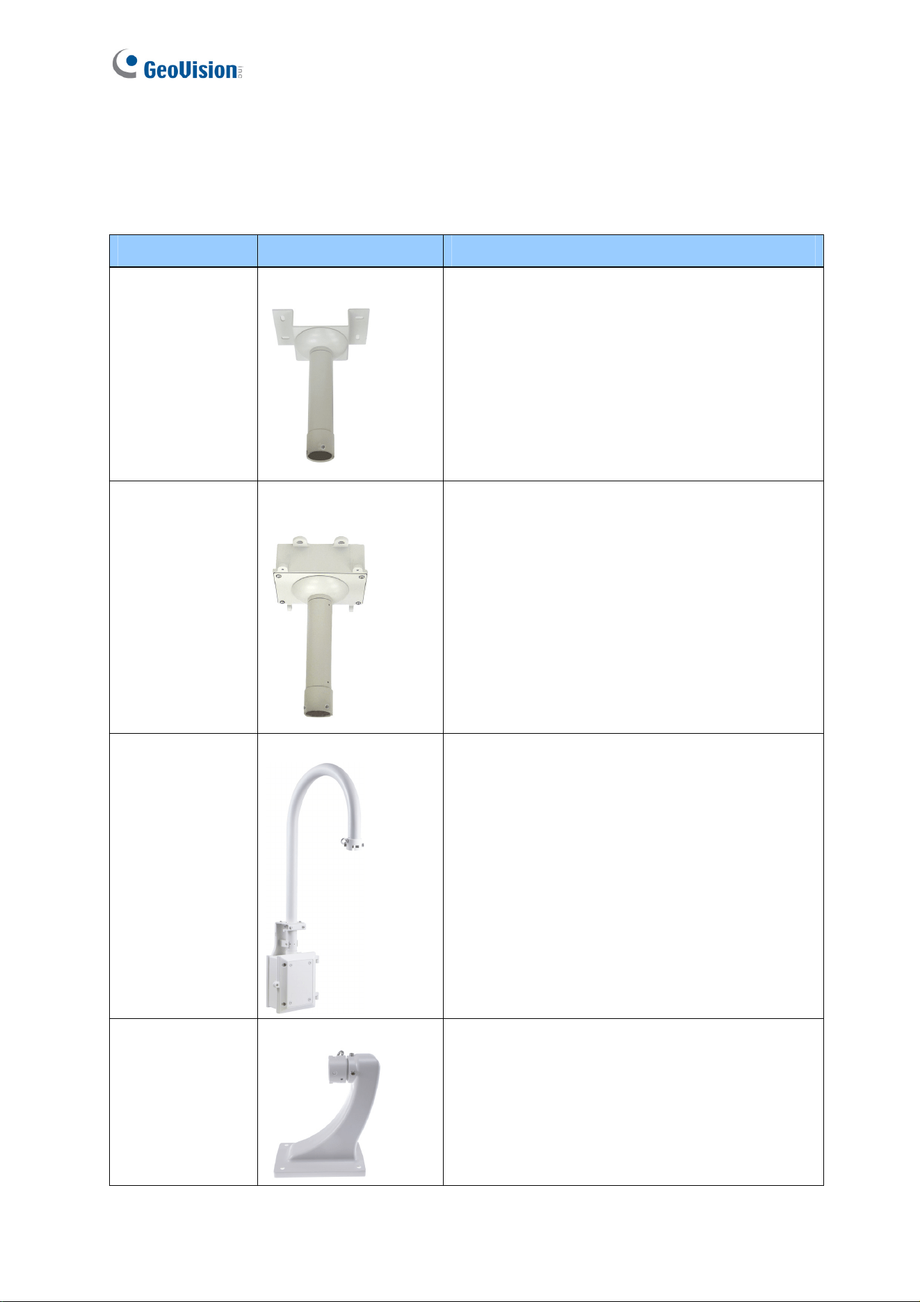
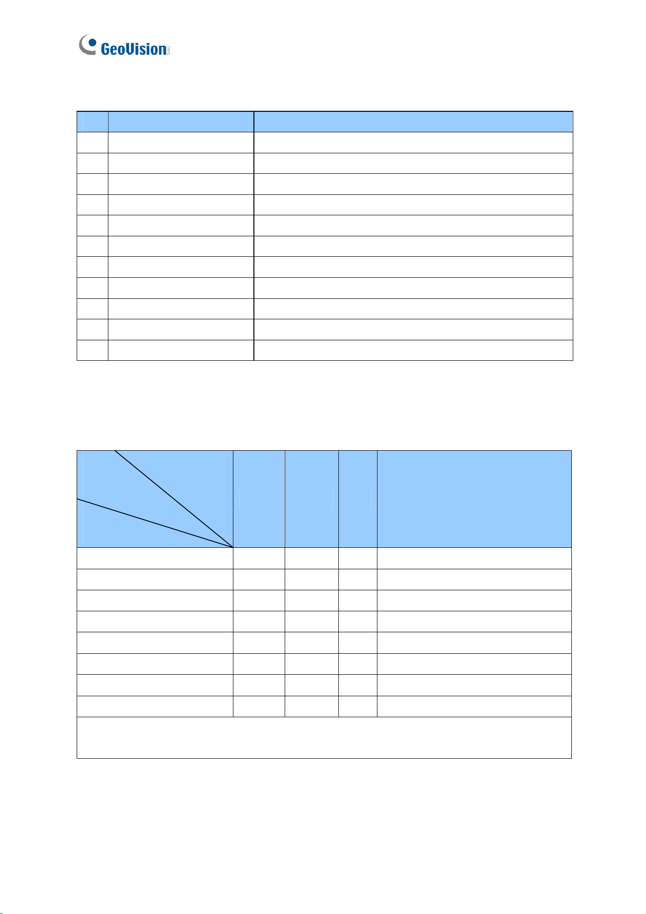
1.4 Optional Accessories
Optional accessories can expand the capabilities and versatility of your GV-IP Speed Dome.
Contact your dealer for more information.
Model Number Name Details
GV-Mount104 Straight Tube Kit
Dimensions: 219 x 125 x 332 mm
(8.6” x 4.9” x 13.1”)
Weight: 1.8 kg (3.97 lb)
GV-Mount105
Straight Tube and
Junction Box Kit
Dimensions: 256 x 256 x 297 mm
(10.1” x 10.1” x 11.7”)
Weight: 6.2 kg (13.67 lb)
GV-Mount208-3
Swan Neck Mount
Dimensions: 1043 x 519 x 256 mm
(41.06 x 20.43 x 10.08")
Weight: 10.6 kg (23.37 lb)
GV-Mount210
Pendant Tube
Dimensions: 200 x 140 x 249 mm
(7.9” x 5.5” x 9.80”)
Weight: 1.1 kg (2.43 lb)
Introduction
7
1
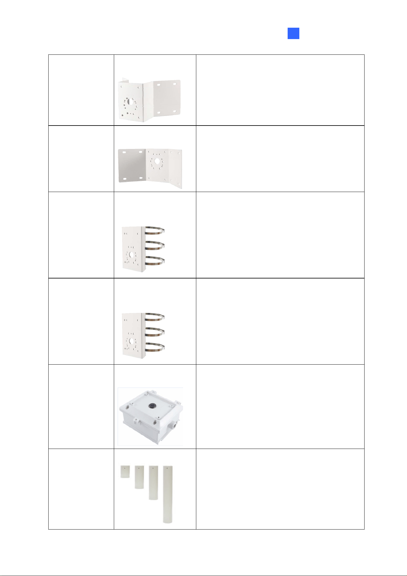
GV-Mount300-1
Convex Corner
Adapter Kit
Dimensions: 238.6 x 395.2 x 210 mm
(9.4’’ x 15.5” x 8.2”)
Weight: 4.27 kg (9.41 lb)
GV-Mount310-1
Concave Corner
Adapter Kit
Dimensions: 111.2 x 369.9 x 210 mm
(4.37’’ x 14.5” x 8.2”)
Weight: 2.96 kg (6.53 lb)
GV-Mount400-1
Pole Mount Bracket
Kit
(Ø 4" ~ 6")
Dimensions:
Bracket: 68.4 x 240 x 163 mm
(2.69” x 9.44’’ x 6.41”)
Weight: 1.70 kg (3.75 lb)
Steel Strap Diameter: Ø 4" ~ 6"
GV-Mount410-1
Pole Mount Bracket
Kit
(Ø 6" ~ 7.5")
Dimensions:
Bracket: 68.4 x 240 x 163 mm
(2.69” x 9.44’’ x 6.41”)
Weight: 1.70 kg (3.75 lb)
Steel Strap Diameter: Ø 6" ~ 7.5"
GV-Mount501
Convex Corner Box
Mount
Dimensions: 136 x 256 x 256 mm
(5.4 x 10.1 x 10.1”)
Weight: 4.8 kg (10.6 lb)
GV-Mount702 Extension Tube
Four options are available.
Dimensions: Ø 5.4 x 10 or 20 or 30 or 50 cm
(Ø 2.1” x 3.9” or 7.9” or 11.8” or 19.7”)
Weight: 180 g or 390 g or 550 g or 800 g
(0.4 lb or 0.86 lb or 1.21 lb or 1.76 lb)
8
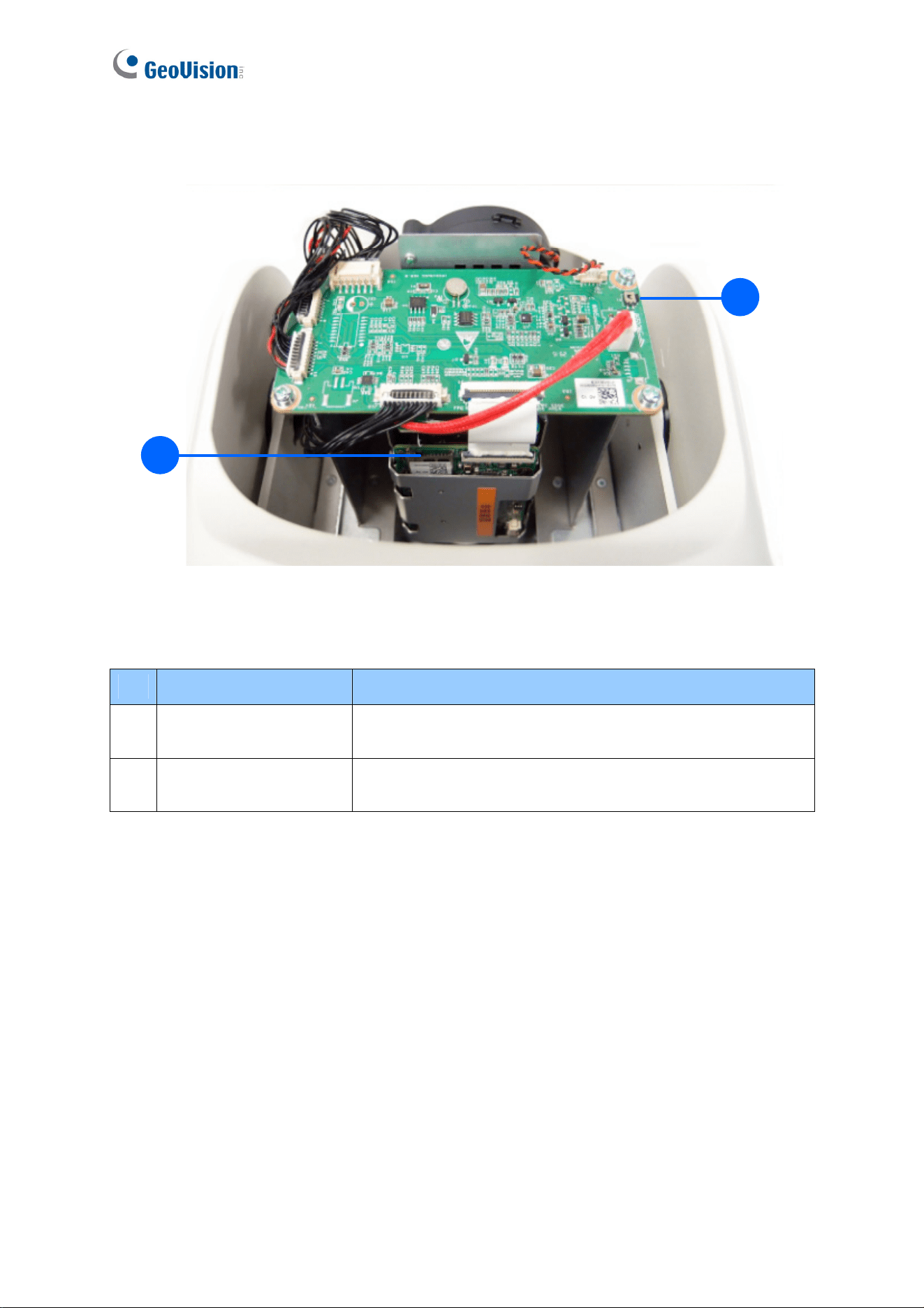
1.5 Physical Description
2
1
Figure 1-1
No. Name Function
1. Default Button
Resets all configurations to default factory settings. See
6.2 Restoring to Factory Default Settings.
2. Micro SD Card Slot
Inserts a micro SD card (SDHC/SDXC, Class 10) to store
recording data.
Introduction
9
1
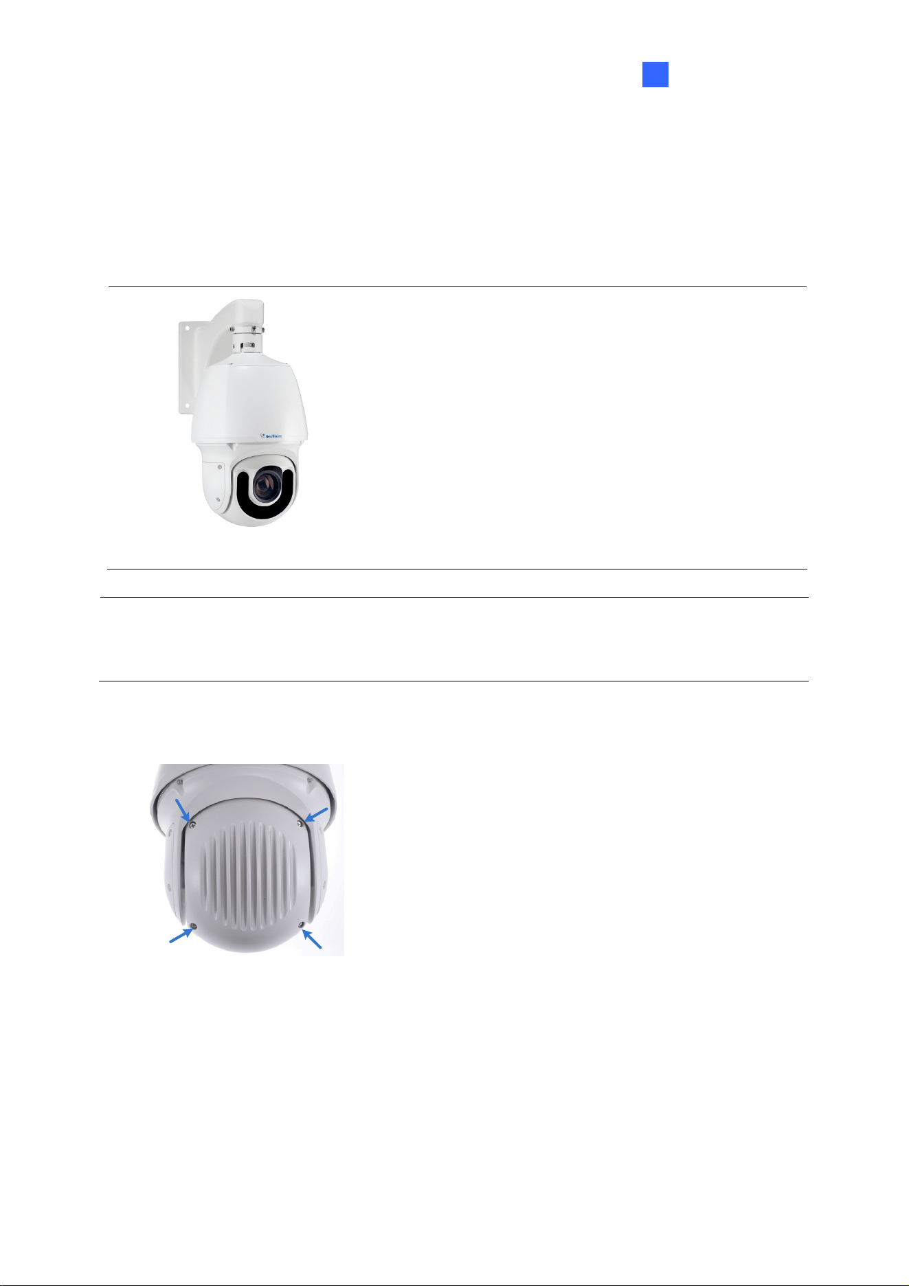
1.6 Accessory Installation (Wall Pendant Mount)
You can separately purchase optional mounting accessories to mount your GV-IP Speed
Dome on a wall, ceiling or pole. Make sure the wall is strong enough to support the camera
and the mount.
Figure 1-2
Required Items
GV-Mount210 (purchased required)
Wall screws x 4 (user-prepared)
Note: GV-SD2722-IR / SD3732-IR supports a series of Intelligent functions, which work best
when the installation abides by specific requirements. See 4.6.1 Recommended Scenario for
details.
1. Unscrew the back cover of the camera.
Figure 1-3
10
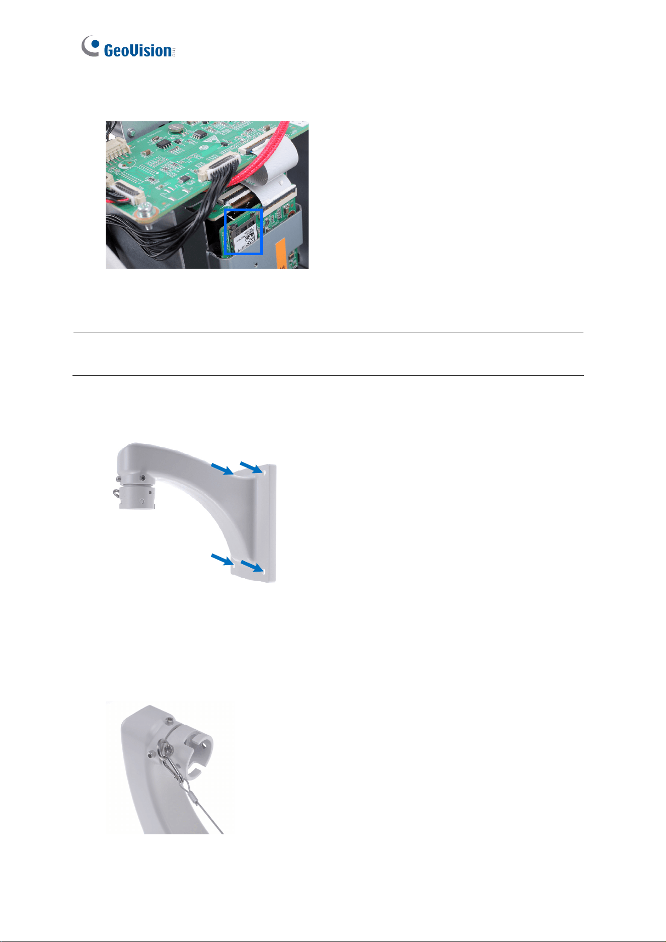
2. Insert the micro SD card into the slot, and secure the back cover of the camera.
Figure 1-4
Note: Be sure to format the memory card on the camera’s Web interface. See 4.7.1
Storage for details.
3. Place the pendant tube on the wall, and mark the position of the screw holes.
Figure 1-5
4. Drill holes on the wall, and secure the pendant tube to the wall with 4 self-prepared
screws.
5. Attach the safety lock of the camera to the pendant tube.
Figure 1-6
Introduction
11
1
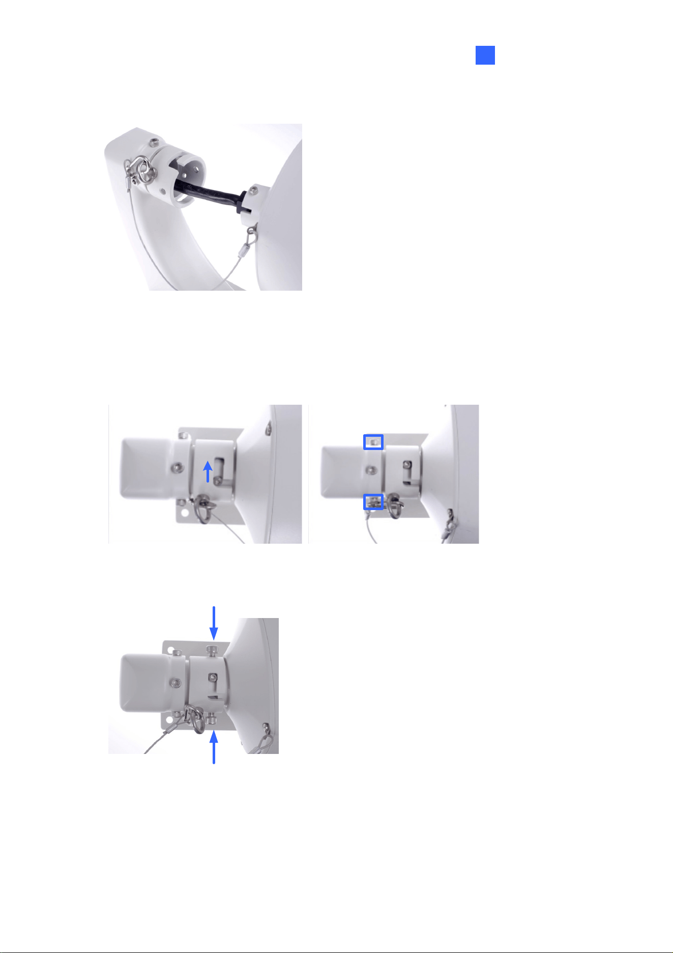
6. Thread the data cable through the pendant tube.
Figure 1-7
7. Attach the camera to the pendant tube, rotate the camera until it is locked into position,
and secure the indicated screws.
Figure 1-8
8. Insert the pendant mount screws and tighten with the supplied M4 hex key.
Figure 1-9
12
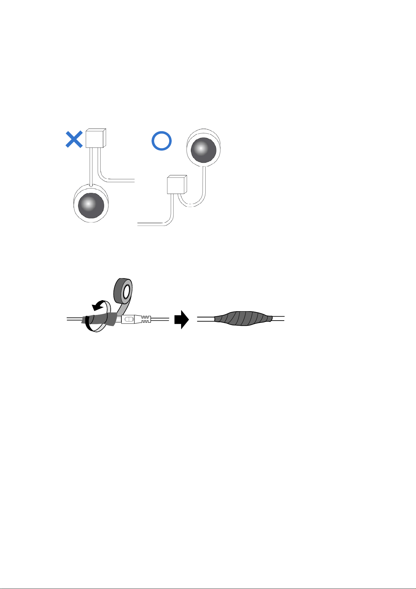
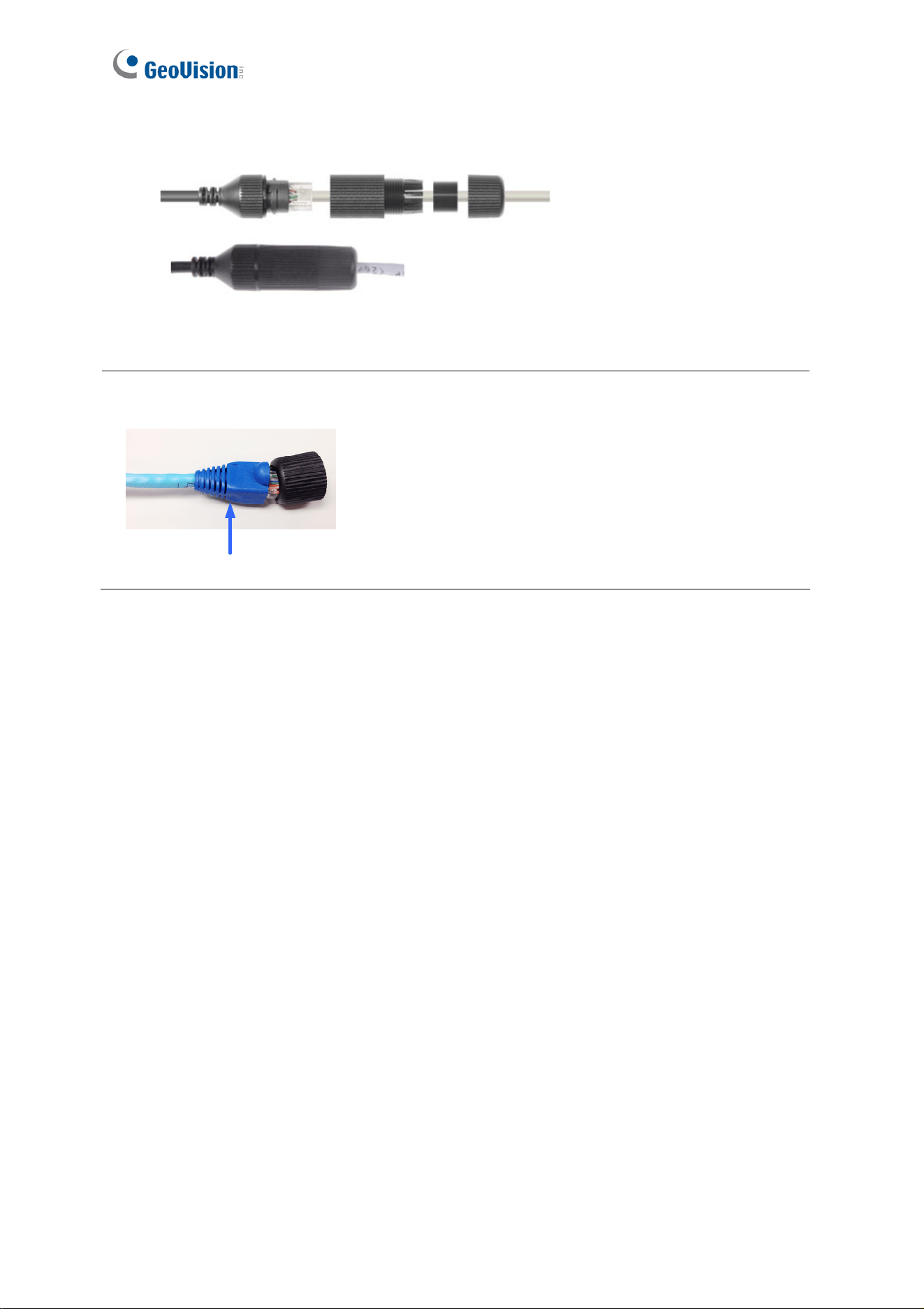
9. Thread the Ethernet cable through the waterproof rubber set as shown below.
Figure 1-10
Note: The size of RJ-45 connector must be within 14 mm to go through the waterproof
rubber set.
Unfit size of RJ45 Connector
Introduction
13
1
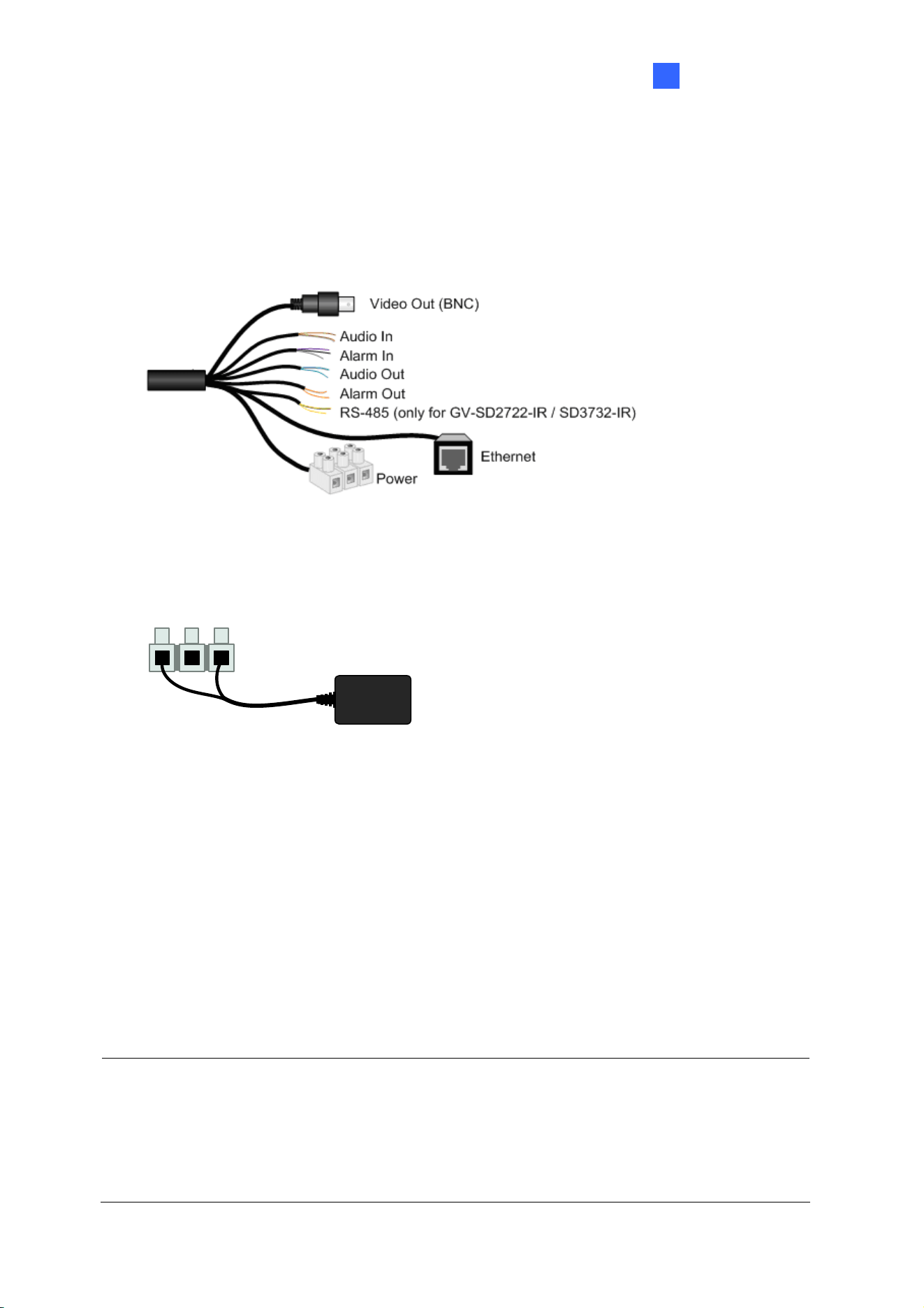
1.7 Connecting the Camera
The camera comes with a data cable that allows you to connect the camera to the power
adapter, microphone, speaker, and I/O devices.
Figure 1-
11
1. Connect the supplied power adapter to the 3-pin terminal block. Either of the red or
black cables can be used for anode (+) and the cathode (-).
Power Adaptor
Figure 1-12
2. Connect a standard network cable to the Ethernet cable of the camera.
3. Optionally connect the TV-out (BNC) cable to a monitor. The TV-out function can be
used during installation to adjust the camera image.
4. Optionally connect I/O devices, speaker and microphone to the camera. You can
connect up to 2 alarm inputs and 1 output device. See Wire Definition section below.
Each time the camera is powered on, it will perform a self-test to check the Pan/Tilt/Zoom
(PTZ) function. After the self-test, you can operate the camera.
Note:
1. When the working temperature is below zero degree Celsius, it may take up to 30
minutes for the camera to finish the pre-heating process.
2. If you are using your own power adapter, you may need to ground the camera using the
yellow cable (GND) on the 3-pin terminal block.
14
Wire Definition
No. Wire Definition
1 Brown Audio in
2 Brown / White GND
3 Green Audio out
4 Green / White GND
5 Gray Alarm IN 1
6 Purple Alarm IN 2
7 Black GND
8 Orange Alarm In -
9 Orange / White Alarm Out +
10 Yellow RS-485 – (only for GV-SD2722-IR / SD3732-IR)
11 Yellow / Black RS-485 + (only for GV-SD2722-IR / SD3732-IR)
Power cable
The power loss in watts on the cable for different lengths and different core diameters is
listed below.
Core Diameter
(Unit: mm)
Distance
(Unit: m)
Power
(Unit: W)
0.80 1.00 1.25 2.00
30 28 45 72 183
40 21 34 54 137
50 17 27 43 110
60 - 22 36 91
70 - 19 31 78
80 - - 27 68
90 - - 24 61
100 - - 21 55
Note: Data listed above is applicable to copper cables that use 24V AC / 24V DC power
supply.

Accessing the Camera
15
2
Chapter 2 Accessing the Camera
Once installed, the IP Speed Dome is accessible on a network. Follow these steps to
configure the network settings and access your surveillance images.
2.1 Installing on a Network
These instructions describe the basic connections to install the camera on the network.
1. Using a standard network cable, connect the camera to your network.
2. Connect to power using the supplied power adapter.
3. You can now access the Web interface of the camera.
If the camera is installed in a LAN with DHCP server, use GV-IP Device Utility to look
up the camera’s dynamic IP address. See 2.1.1 Checking the Dynamic IP Address.
If the camera is installed in a LAN without DHCP server, the default IP address
192.168.0.10 is applied. To assign a different static IP address, see 2.1.2 Assigning
an IP Address.
Note: You must set your browser to allow ActiveX Controls and perform a one-time
installation of the ActiveX component onto your computer at your first login.
16
2.1.1 Checking the Dynamic IP Address
1. Download and install the GV-IP Device Utility program from the company website
Note: The PC installed with GV-IP Device Utility must be under the same LAN with the
camera you wish to configure.
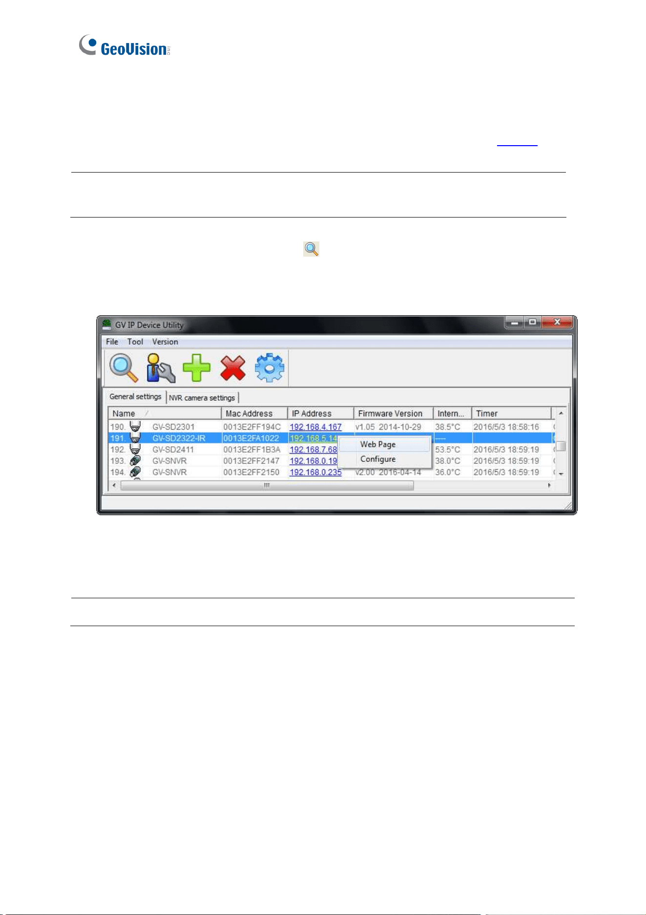
2. On the GV-IP Utility window, click the
button to search for the IP devices connected
in the same LAN. Click the Name or Mac Address column to sort.
3. Find the camera with its Mac Address, click on its IP address and select Web Page.
Figure 2-1
4. In the login page, type the default ID and password admin and click Apply to login.
Note: Multilingual Web interface is only supported by GV-SD2722-IR / SD3732-IR.
Accessing the Camera
17
2
2.1.2 Assigning an IP Address
To assign a new static IP address, log in the Web interface to access the network setting
page.
Note: If your router does not support DHCP, the default IP address will be 192.168.0.10.
In this case, it is highly recommended that you modify the IP address to avoid IP address
conflict with other GV-IP devices on the same LAN.
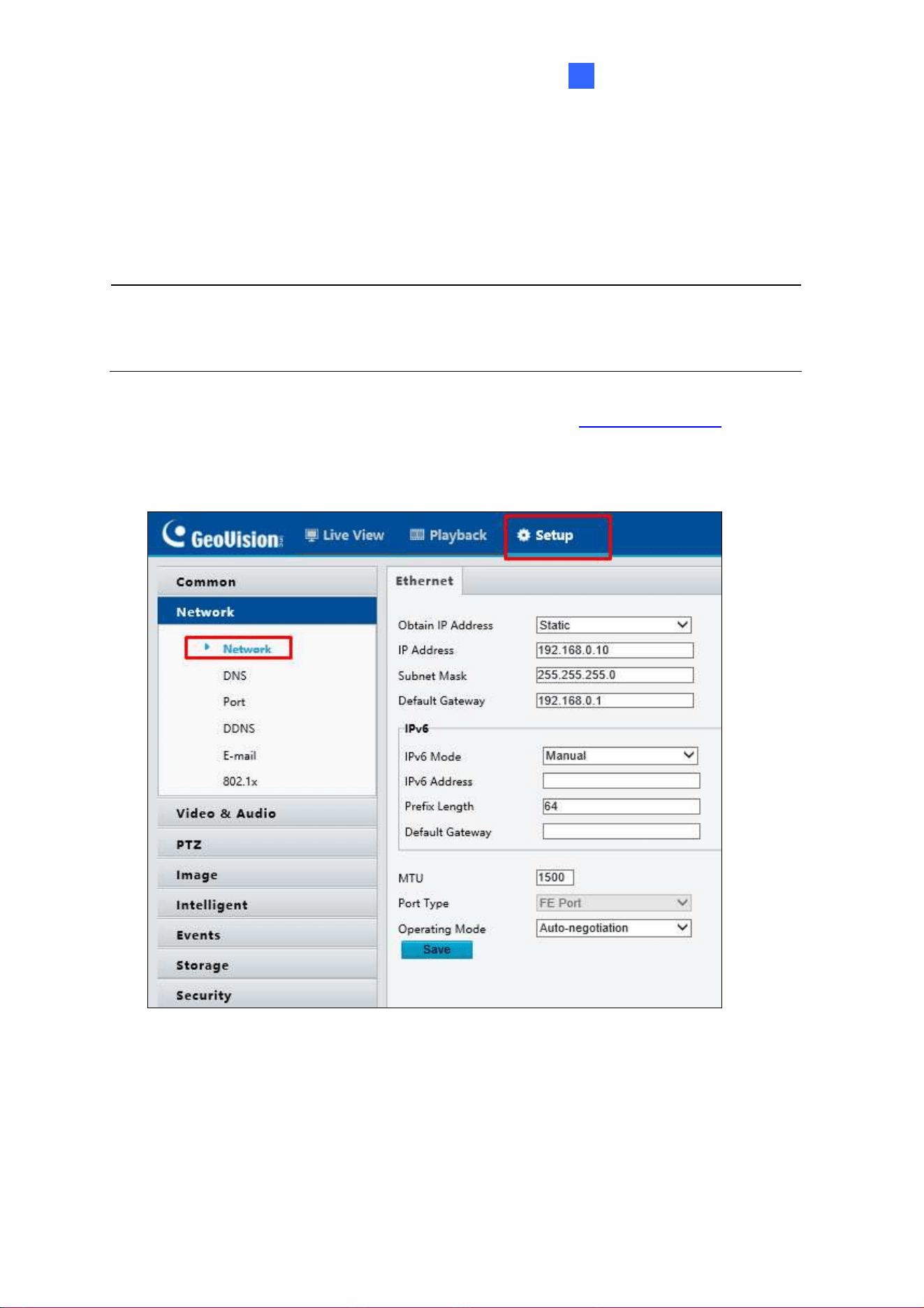
1. Open your web browser, and type the default IP address http://192.168.0.10.
2. Type the default username and password admin. Click Login.
3. Click Setup, select Network in the left menu and select TCP/IP / Network.
Figure 2-2
4. Select Static from the Obtain IP Address drop-down list.
5. Enter the IP address, subnet mask, and default gateway address. Make sure that the IP
address of the camera is unique in the network.
6. Click Save.
18
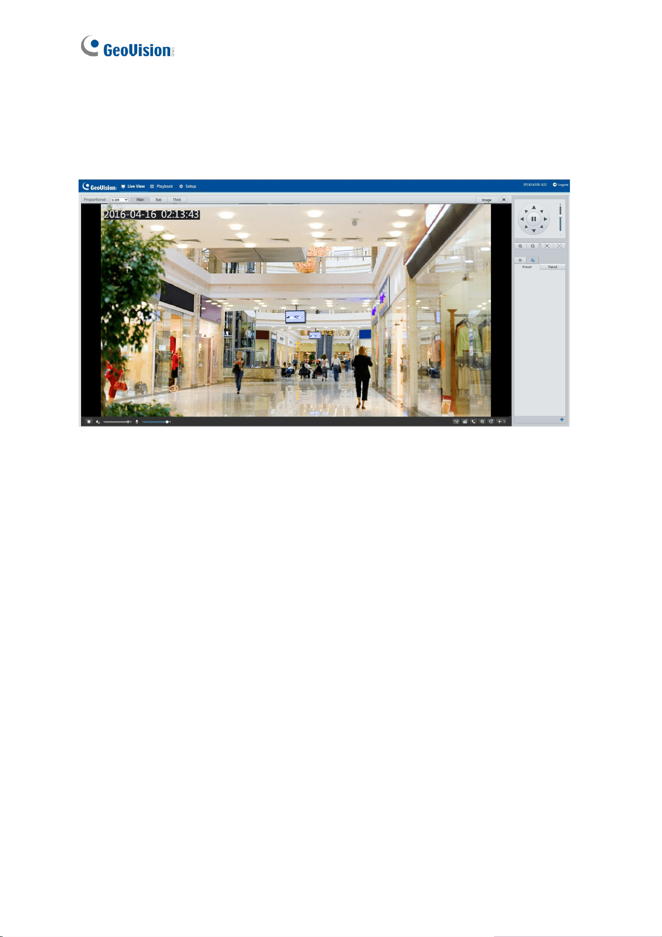
2.2 Accessing Live View
After logging in to the speed dome, you will see the Home page as shown below:
Figure 2-3
Accessing the Camera
19
2
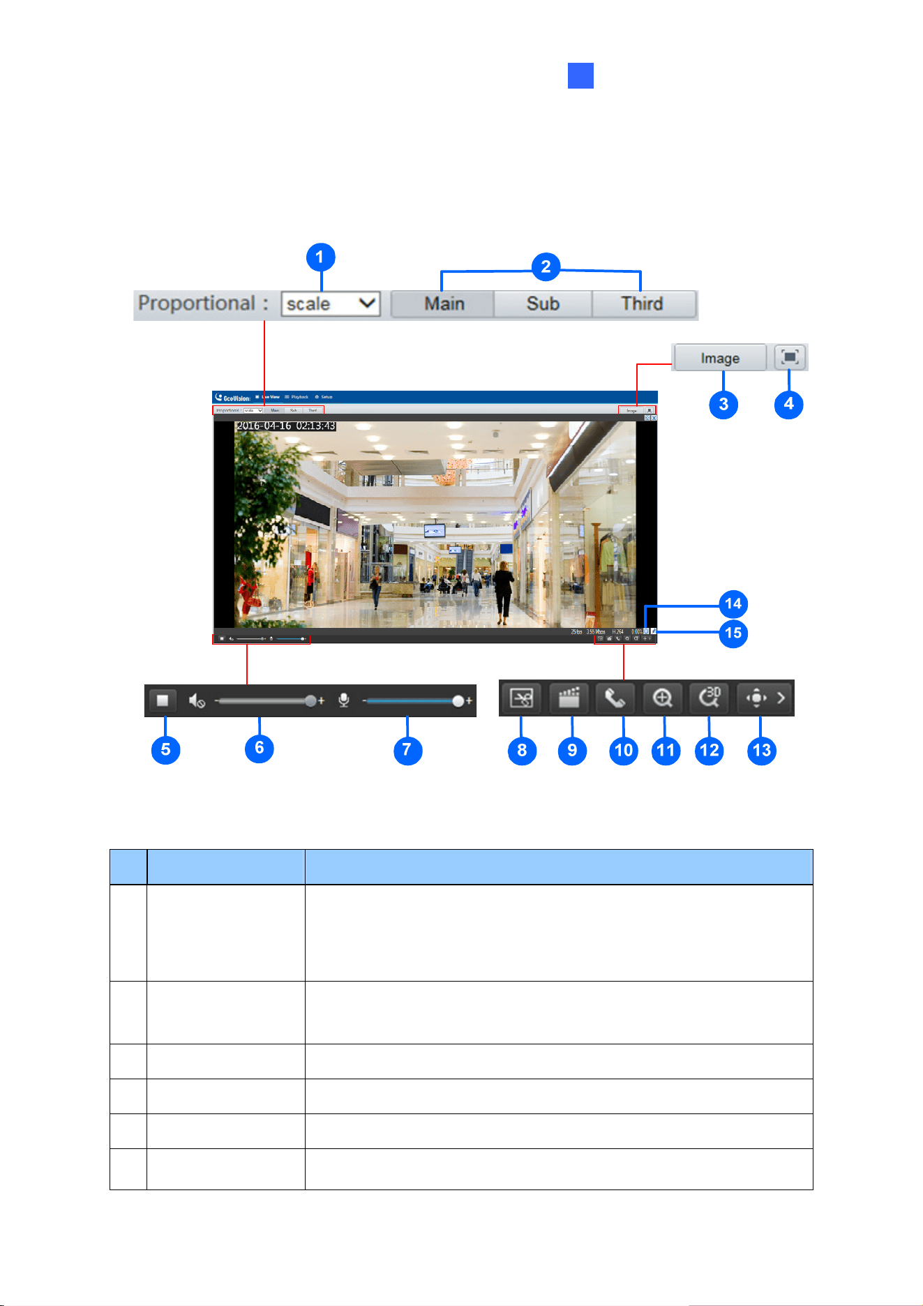
2.2.1 The Live View Window
For GV-SD2322-IR
Figure 2-4
No. Name Function
1 Proportional
Set the display ratio of the image.
Scale: display images by 16:9.
Stretch: display images by window size.
Original: display images in its original size.
2 Live Stream
Select a live video stream: main stream, sub stream or third
stream.
3 Image Open the image setting page. – See 4.5.1 Image.
4 Full Screen Mode Display in full screen mode.
5 Play/Stop Play or stop live video.
6 Volume
Adjust the audio output volume on the PC.
20
7 Microphone
Adjust the microphone volume on the PC during audio
communication between the PC and the camera.
8 Snapshot Take a snapshot of the current image displayed on the PC.
9 Local Recording Start or stop local recording.
10
Audio
Communication
Start
or stop audio communication between the PC and
the camera.
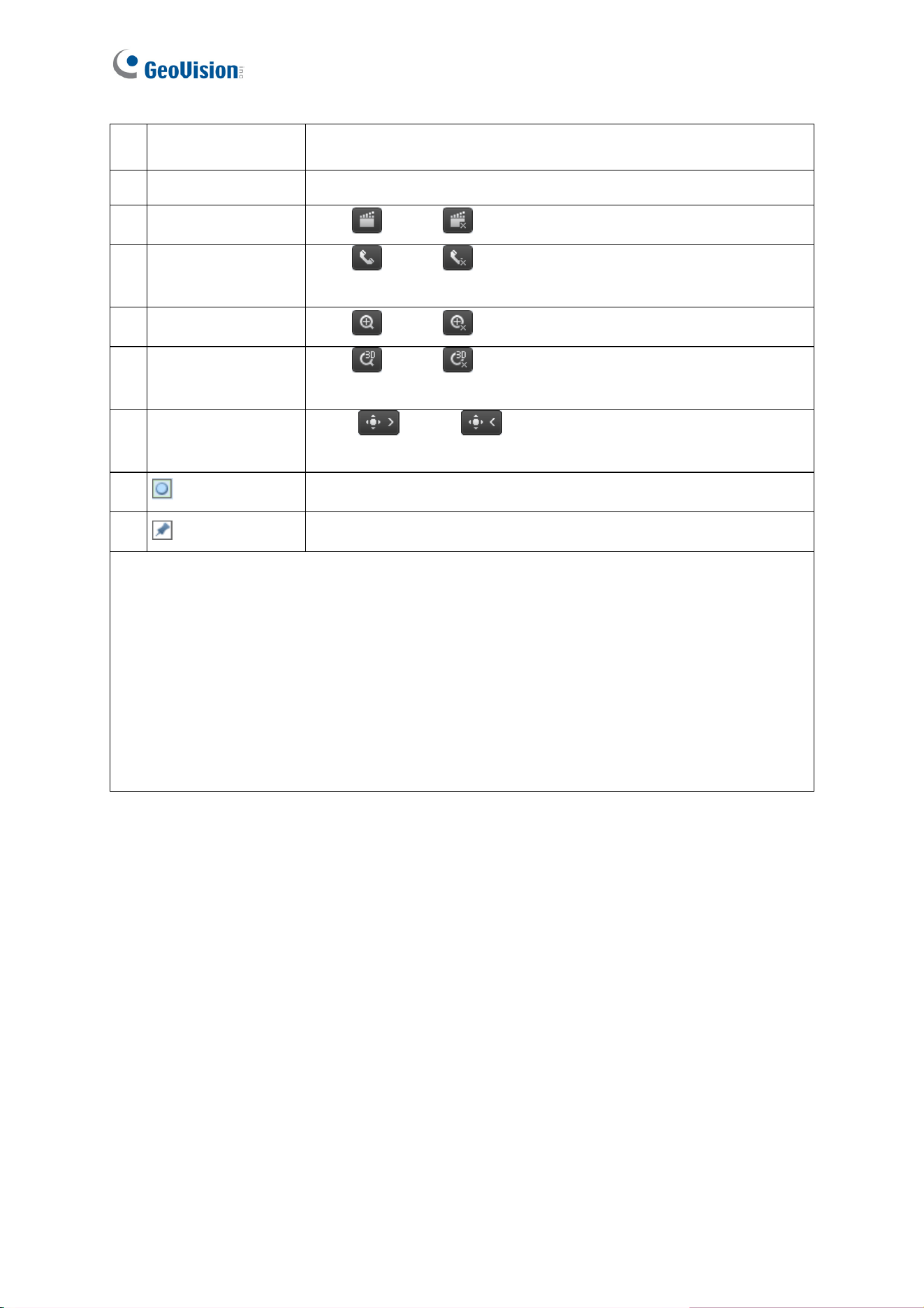
11 Digital Zoom Start or stop digital zoom. -- See 2.2.1.1 Digital Zoom.
12 3D Positioning
Start
or stop 3D positioning (optical zoom). -- See 2.2.1.2
3D Positioning.
13 PTZ control panel
Show
or hide the PTZ control panel. -- See 3. PTZ
Control Panel.
14 Reset the packet loss rate to zero.
15 Display packet loss rate and bit rate information in the bottom.
Note:
1. The paths for saving snapshots and local recordings are set in System Configuration.
2. The buttons (No. 14 and No. 15) will appear on the floating toolbar after you move the
mouse cursor on a live view window.
3. Click the button (No. 15) to display the bottom information. Click this button again, the
bottom information is displayed if the mouse cursor is moved on a live view window or
on the bottom information, and it hides automatically if the mouse cursor remains on a
live view window for 3 seconds or leaves the window.
Accessing the Camera
21
2
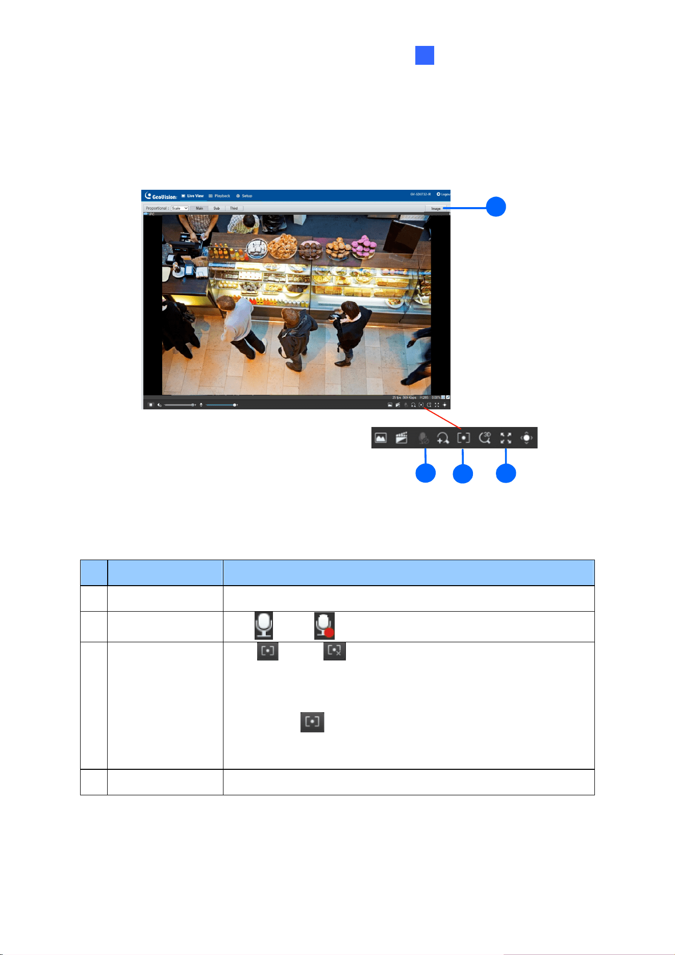
For GV-SD2722-IR / SD3732-IR
1
1
3
2
4
Figure 2-5
No. Name Function
1 Image Open the image setting page. -- See 4.5.1 Image.
2 Two-way Audio
Start
or stop two-way audio.
3 Area Focus
Start
or stop area focus.
By activating this function, you can set the camera focus based on
a defined area of the live view. To activate Area Focus, follow the
steps below:
Step 1: Click
on the toolbar.
Step 2: Click and drag on the live view to specify an area. The
focus of the live view changes to the specified area.
4 Full Screen Mode Display in full screen mode.
For other functions in the live view window, refer to Figure 2-4.
22
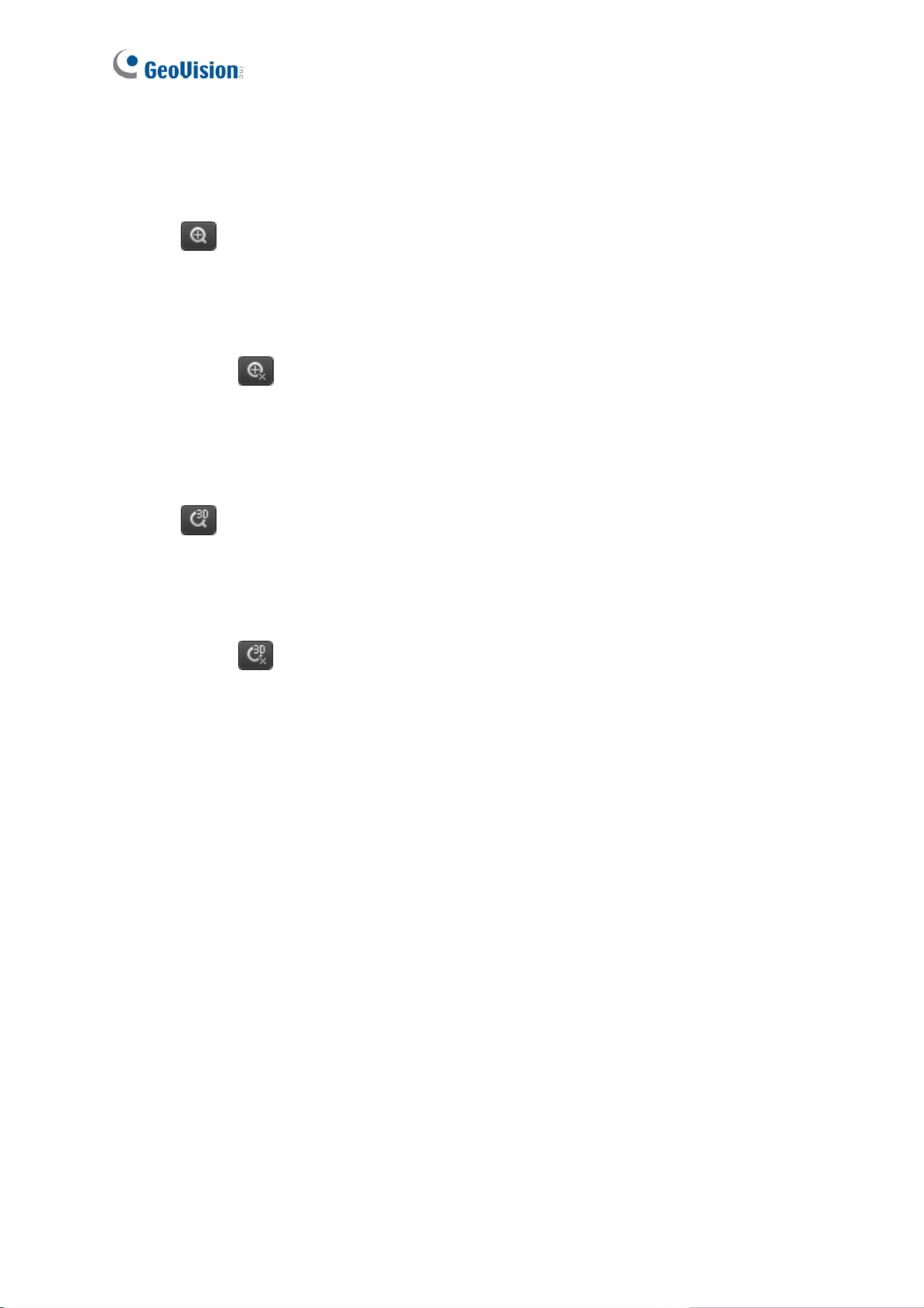
2.2.1.1 Digital Zoom
To use the digital zoom function, follow these steps:
1. Click
(No. 11, Figure 2-4) on the toolbar.
2. Click and drag on the live view from top to down to specify an area.
3. To restore the original image size, click in the enlarged area, or drag from the bottom up.
4. To exit, click
(No. 11, Figure 2-4) on the toolbar.
2.2.1.2 3D Positioning (Optical Zoom)
1. Click (No. 12, Figure 2-4) on the toolbar.
2. Click and drag on the live view from top to down to specify an area.
3. To zoom out, drag from the bottom up.
4. To exit, click
(No. 12, Figure 2-4) on the toolbar.
23
Chapter 3 PTZ Control Panel
In this chapter, you will be guided through the various functions of PTZ Control Panel. The
PTZ Control Panel is accessed from the live view interface of the camera.
3.1 Assessing the PTZ Control Panel
2
3
5
8
7
4
6
1
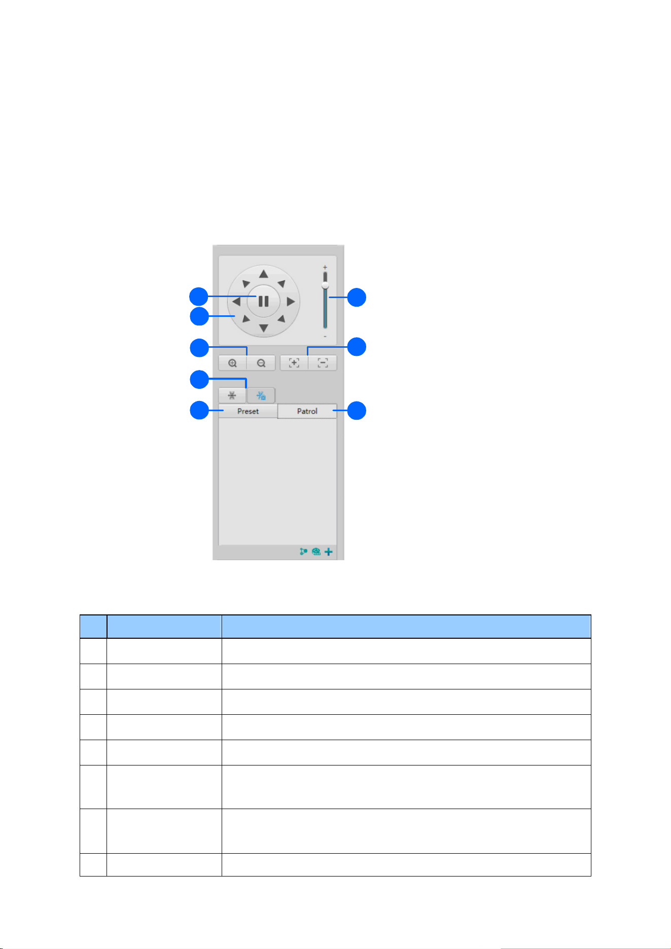
Figure 3-1
No. Item Function
1 Auto Pan
Start or stop auto panning of the camera.
2
PTZ Control Panel Control the direction of the camera and release the control.
3
PTZ Speed
Adjust the moving speed of the PTZ camera.
4
Zoom
Adjust the camera’s zoom (optical).
5
Focus
Adjust the camera’s focus.
6
Snow
Turn on or off the snow control. When enabled, the camera will
rotate to remove accumulated snow if detected by the camera.
7 Preset
Select a preset and the camera goes to the selected preset.
-- See 3.1.1 Setting Presets.
8 Patrol Select a patrol route. -- See 3.1.2 Setting Patrol.
24
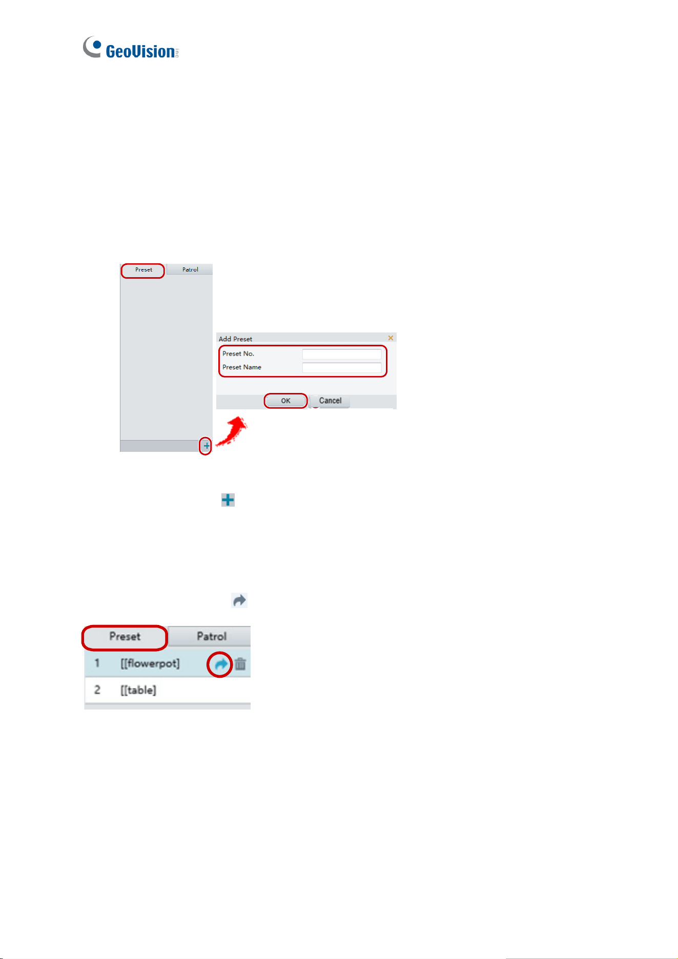
3.1.1 Setting Presets
You can create and delete preset points by clicking Preset on the control panel of Live View.
Adding a Preset
1. Once Preset (No.7, Figure 3-1) is selected in the control panel, adjust the dome view to
the desired direction, zoom and focus.
4
Figure 3-2
2. Click the Add button
to add it as a preset.
3. Enter a number and name for the preset and click OK.
Going to a Preset
On the control panel, click for a preset. The PTZ camera goes to the selected preset.
Figure 3-3
PTZ Control Panel
25
3
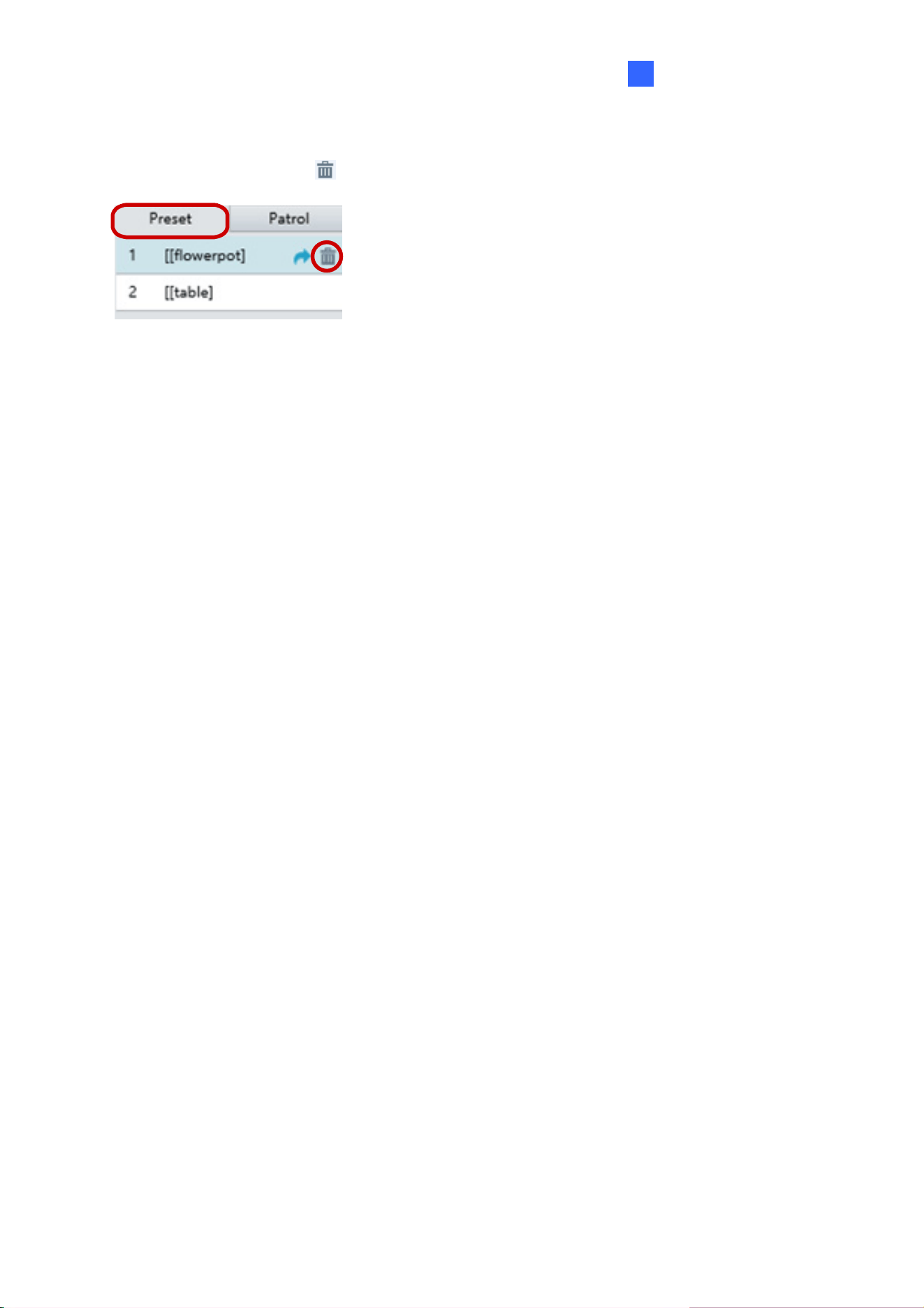
Deleting a Preset
On the control panel, click for a preset and confirm the delete.
Figure 3-4
26
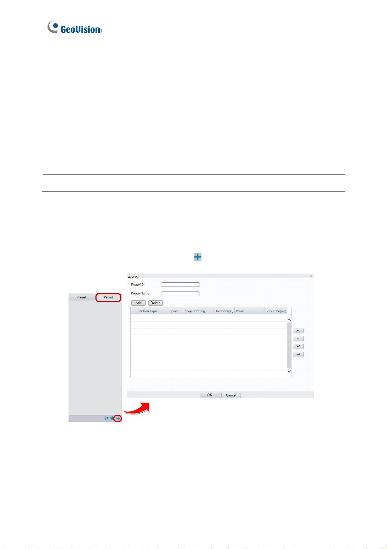
3.1.2 Setting Patrol
A patrol route is the track by which the camera follows when moving from a preset to the next.
The length of time that the camera stays at each preset is configurable. Multiple patrol routes
are allowed for the camera.
Patrol actions include going to a preset and staying at the preset for a certain amount of time
before going to the next. You can set the rotation direction, zoom, rotation speed, patrol time,
and stay time. You can also record a route and add it to the action list.
Note: To enable Preset Snapshot, see 4.4.3 Patrol.
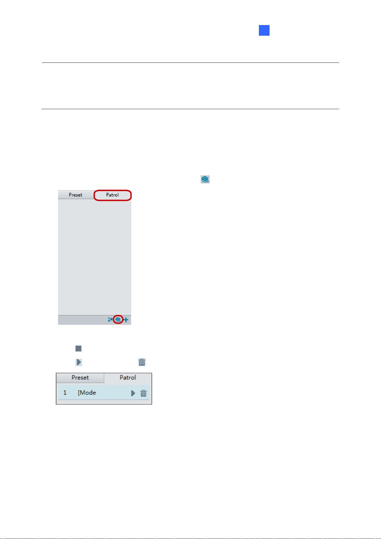
To access the Patrol functions, click Patrol on the control panel of Live View.
Adding a Patrol Route
1. On the control panel, click the Add button to add a patrol route.
Figure 3-5
2. On the Add Patrol page, type the desired route ID and name.
3. Click Add to add a patrol action. Use the buttons to adjust the sequence of the actions
and click OK.
PTZ Control Panel
27
3
Note:
1. It is recommended that the first action type is Go to Preset.
2. If Keep Rotating is selected, the camera will rotate at the set speed and zoom in the set
direction or position for a certain amount of time.
Recording a Patrol Route
You can record the dome movements of the camera as a patrol route. The recorded
movements are added to the action list.
1. On the control panel, click the Record button
to start recording the patrol route.
Figure 3-6
2. Click
to finish recording. The patrol route is saved as a mode route automatically.
3. Click
to start patrol or to delete the mode route.
Figure 3-7
28
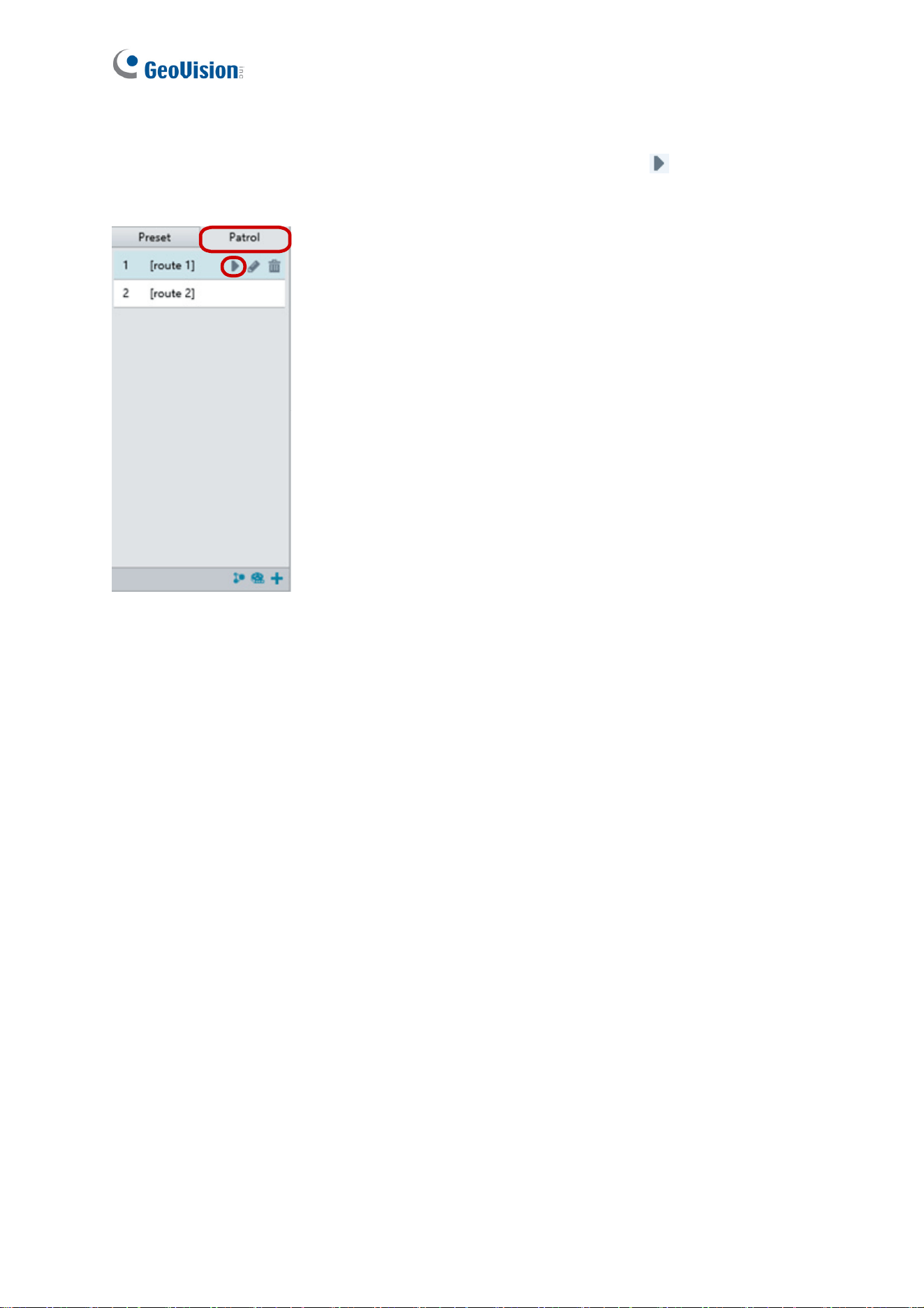
Starting a Patrol Route
After you have added a patrol route, you can start patrolling by clicking on the control
panel.
Figure 3-8
PTZ Control Panel
29
3
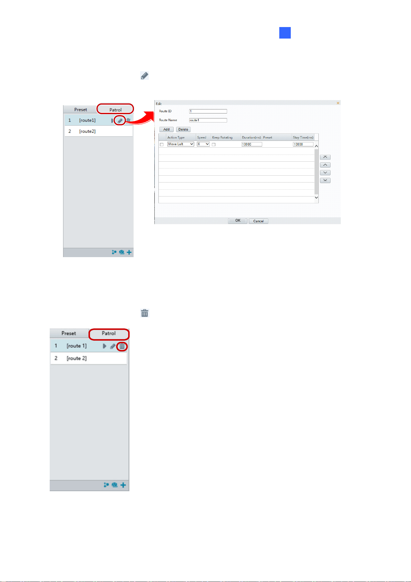
Editing a Patrol Route
On the control panel, click to modify the ID, name and dome movement of an existing
patrol route.
Figure 3-9
Delete a Patrol Route
On the control panel, click for a patrol route and confirm the delete.
Figure 3-10
30
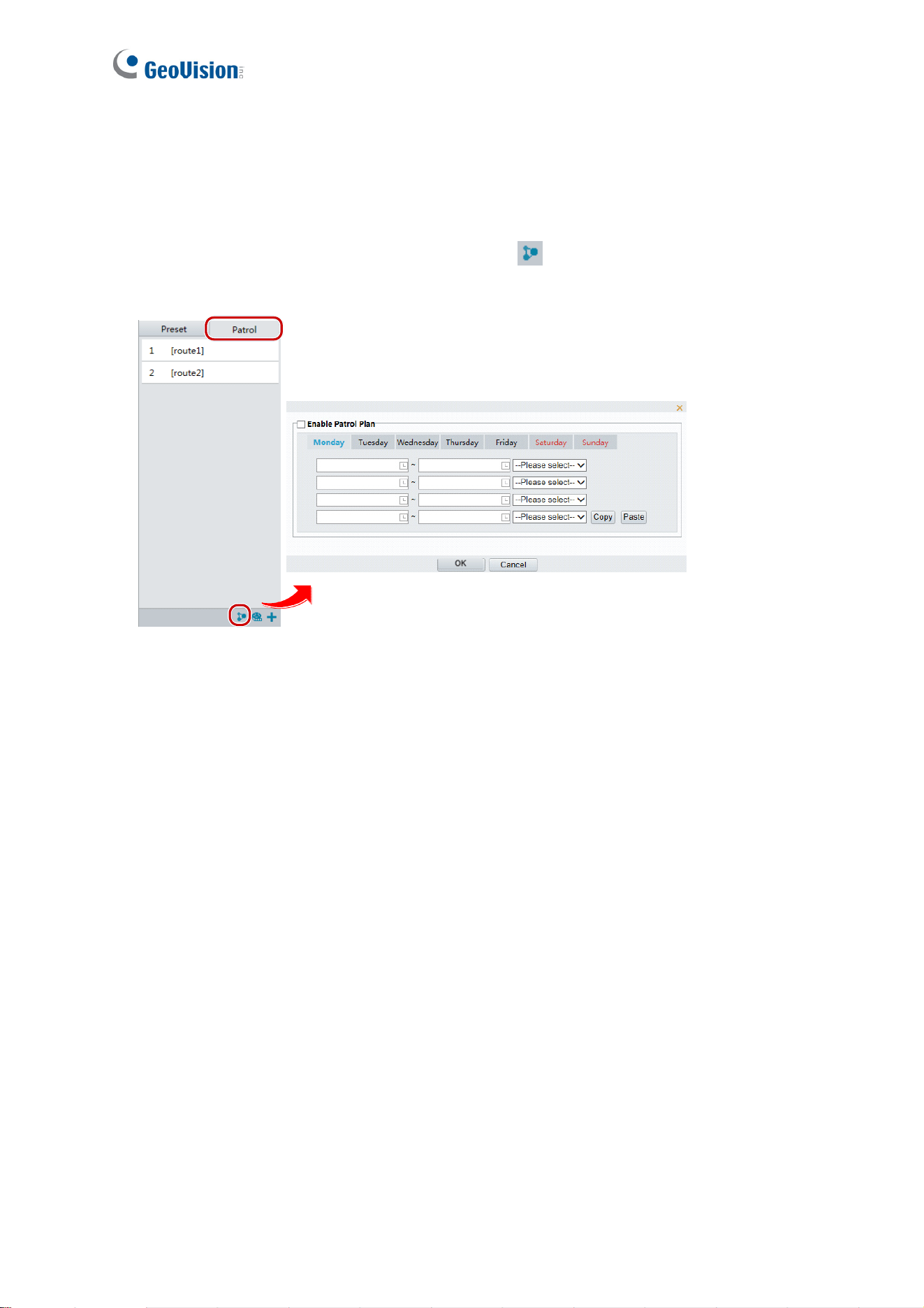
Making a Patrol Plan
You can set up the camera to perform different patrol routes at different time periods
throughout the week by making a patrol plan.
1. On the control panel, click the Patrol Plan button
to set the correct patrol time and
route.
Figure 3-11
2. Select Enable Patrol Plan.
3. Click OK.
PTZ Control Panel
31
3
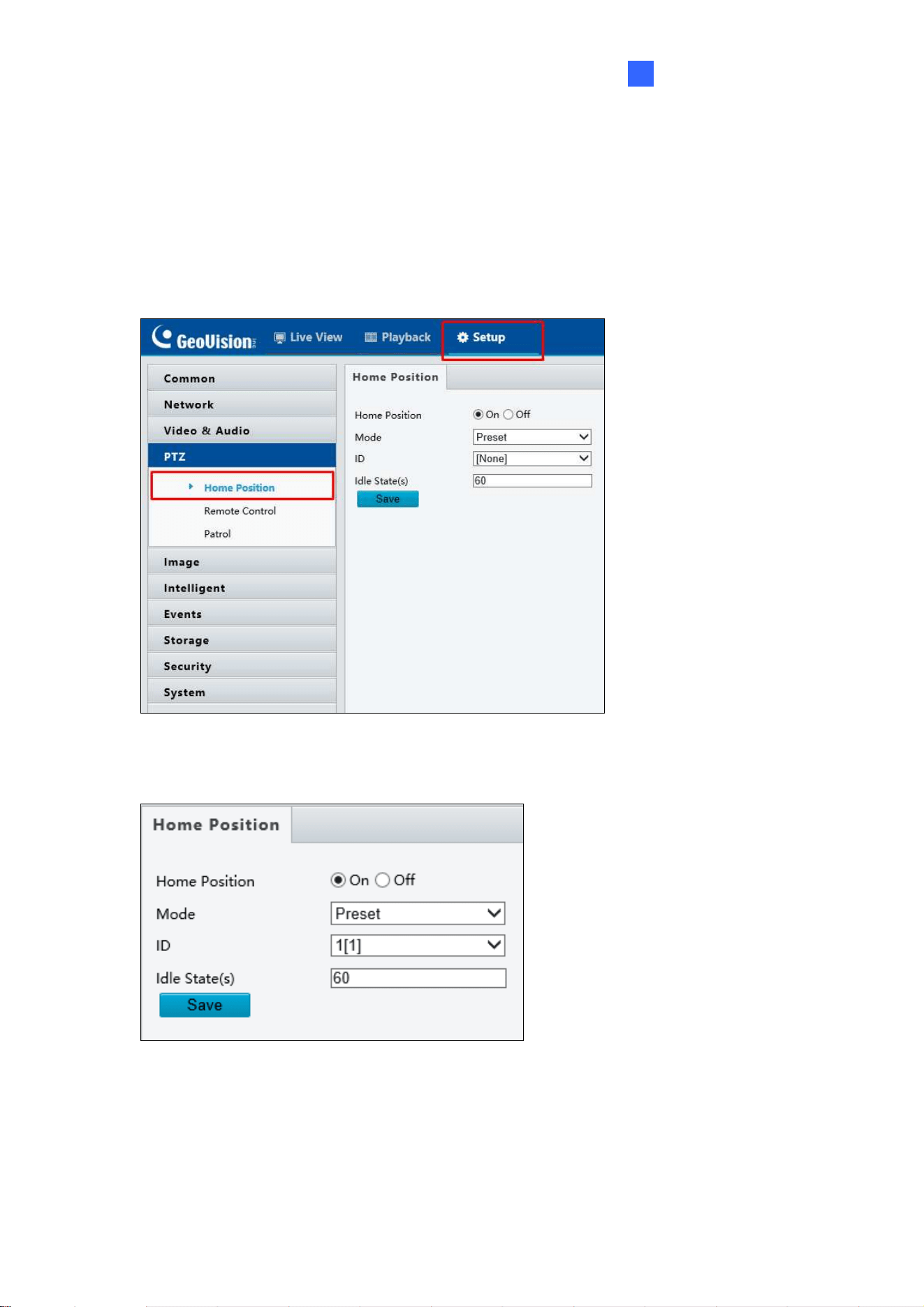
3.2 Setting Home Position
PTZ camera will return to home position if no operation is made within a specified period.
1. On the Setup page, select PTZ in the left menu and select Home Position to access the
settings.
Figure 3-12
2. Select the desired preset as the home position and set the time.
Figure 3-13
3. Click Save.
32
Chapter 4 Administrator Mode
The Administrator can access and configure GV-IP Speed Domes through the network. Click
Setup at the top of the Web interface to access the following nine configuration tabs:
Common, Network, Video & Audio, PTZ, Image, Intelligent, Events, Storage, Security
and System. The configuration tabs may vary based on available models.
Figure 4-1
Administrator Mode
33
4
List of Options
See the table below for the settings available on the Web interface. Find the topic of interest
by referring to the section number prefixed to each option. The configuration tabs and
settings may vary with different models.
4.1 Common
4.1.1 Navigation / Basic Info
4.1.2 Local Settings
4.2 Network
4.2.1 TCP/IP / Network
4.2.2 Port
4.2.3 FTP
4.2.4 E-mail
4.2.5 DDNS
4.2.6 Port Mapping
4.2.7 802.1x
4.3 Video & Audio
4.3.1 Video
4.3.2 Audio
4.3.3 Capture
4.3.4 ROI
4.3.5 Media Stream
4.4 PTZ
4.4.1 Home Position
4.4.2 Remote Control
4.4.3 Patrol
4.5 Image
4.5.1 Image
4.5.2 OSD
4.5.3 Privacy Mask
4.6 Intelligent
4.6.1 Recommended Scenario
4.6.2 Cross Line
4.6.3 Intrusion
4.6.4 Auto Tracking
4.6.5 Advanced Setting
4.7 Events
4.7.1 Motion Detection
4.7.2 Tampering Alarm
4.7.3 Audio Detection
4.7.4 Alarm Input
4.7.5 Alarm Output
4.7.6 Capture
4.7.7 Temperature Alarm
4.8 Storage
4.8.1 Storage
4.8.2 Recording Download
4.9 Security
4.9.1 User
4.9.2 Network Security
34
4.10 System
4.10.1 Time
4.10.2 Maintenance
4.10.3 Security
4.10.4 Ports & Device
Administrator Mode
35
4
4.1 Common
Under the Common tab, the Administrator can find the general settings for the camera, as
well as shortcuts to the following setting pages.
TCP/IP / Ethernet: See 4.2.1 TCP/IP / Network for details.
Time: See 4.10.1 Time for details.
OSD: See 4.5.2 OSD for details
User: See 4.10.3 Security for details
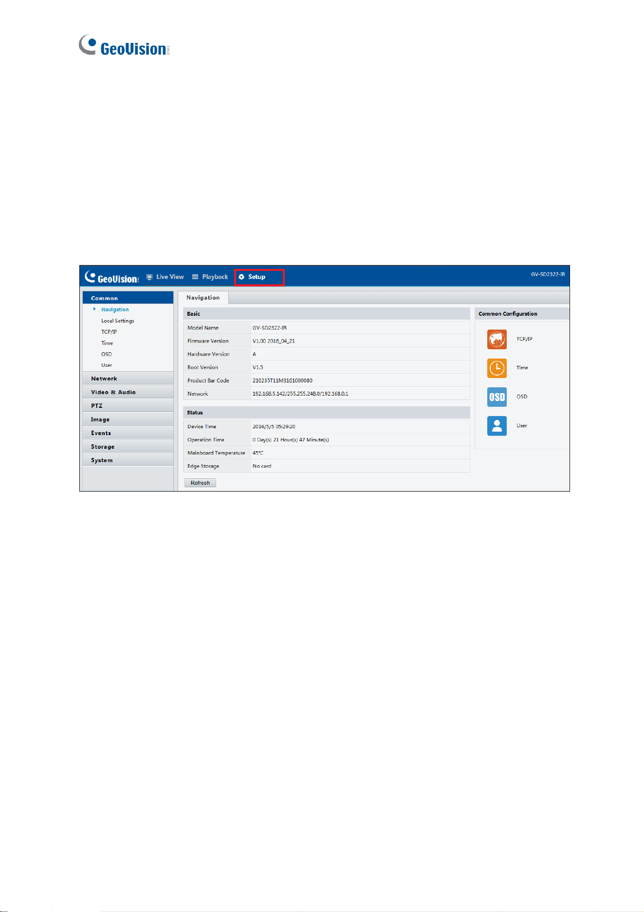
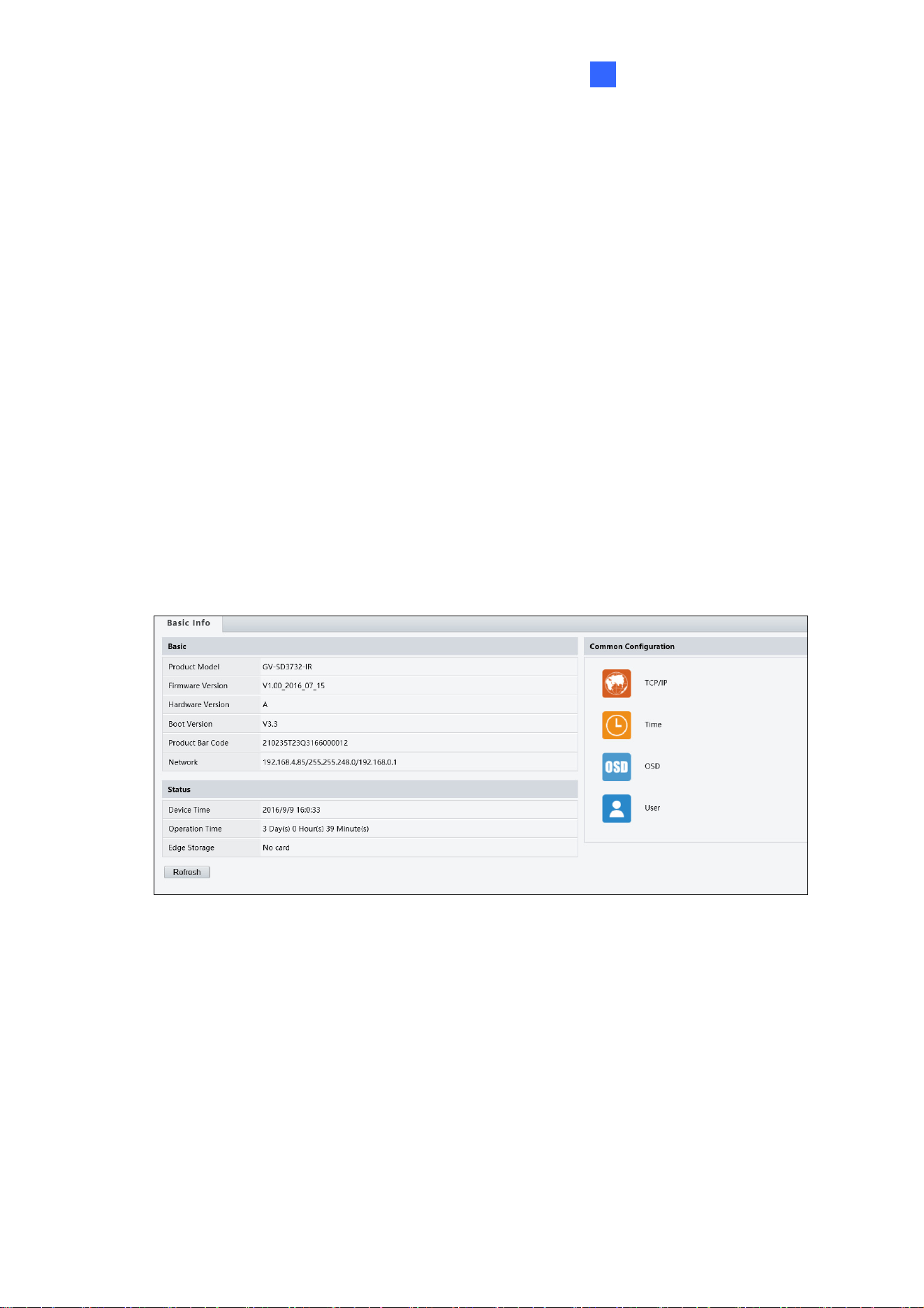
4.1.1 Navigation / Basic Info
You can view the current status of your camera. Click Refresh for the latest status
information. Under Common Configuration on the right, you can click on the icons to quickly
access the configuration pages.
Figure 4-2
36
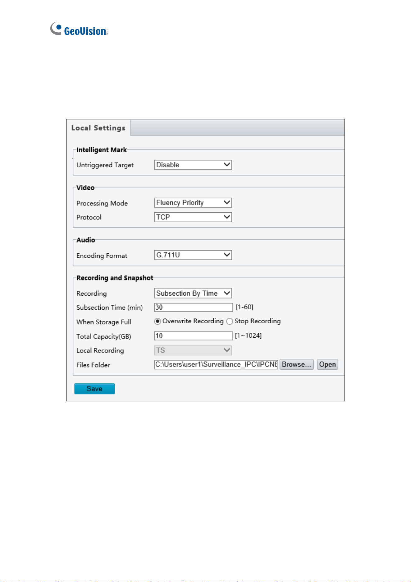
4.1.2 Local Settings
You can set local parameters for your PCs.
Figure 4-3
[Intelligent Mark]
Untriggered Target: Displays the detection lines / detection areas defined by Cross
Line and Intrusion function on Live View. You must set up detection lines / areas first
for this function to work. To set up detection lines / areas, see 4.6.2 Cross Line and
4.6.3 Intrusion, respectively. This function is only applicable to GV-SD2722-IR /
SD3732-IR.

Administrator Mode
37
4
[Video Param / Video]
Processing Mode
Real Time Prior / Real Time Priority: Select this if the network is in good condition.
Fluent Prior / Fluency Priority: Select this if you want short time lag for live video.
Ultra-Low Delay / Ultra-Low Latency: Select this if you want the minimum time lag
for live video.
Video Pixel Format: Select the video format for images at your local computer. It is
recommended to choose YUV420 if the graphic card of your PC supports it. This
function is only applicable to GV-SD2322-IR.
Protocol: Select the protocol used to transmit media streams to be decoded by the PC.
[Audio Param] The audio codec and sampling rate used are shown here.
[Recording and Snapshot]
Recording
Subsection By Time: Set a maximum time length of each recording file. If you
select 5 minutes, a 30-minute event will be chopped into six 5-minute event files.
Subsection by Size: Set a maximum size limit of each recording file.
When Storage Full
Overwrite Recording: When the assigned storage space on the computer is used
up, the camera deletes the existing recording files to make room for the new
recording file.
Stop Recording: When the assigned storage space on the computer is full,
recording stops automatically.
Total Capacity: Set a capacity limit to the assigned storage space on the computer.
Recording Folder / Files Folder: Click Browse to set a folder to store the recorded
videos at your local computer.
Snapshot Folder: Click Browse to set a folder to store the captured snapshots at your
local computer. To assign the snapshot-storing location for GV-SD2722-IR / SD3732-IR,
go to Storage in the left menu and select FTP.
38
4.2 Network
The network section allows you to configure the network settings, modify ports, configure
FTP server, and set up e-mail for notification.
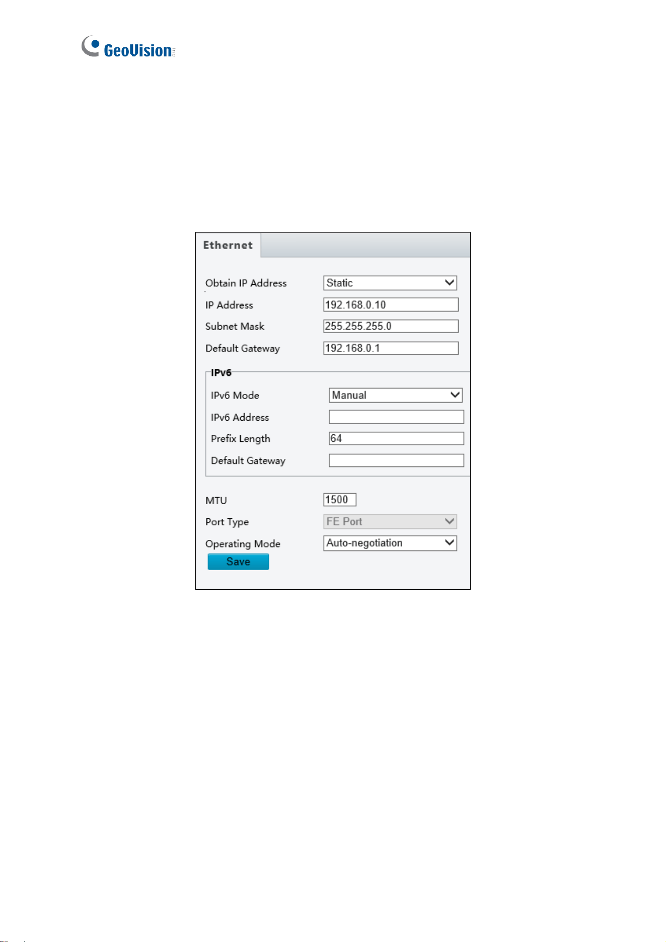
4.2.1 TCP/IP / Network
Figure 4-4
IP Obtain Mode / Obtain IP Address: Select Static IP, PPPoE or DHCP according to
your network environment.

Administrator Mode
39
4
Static IP address: Assign a static IP or fixed IP to the camera. Type the camera’s IP
address, Subnet Mask, Router/Gateway, Preferred DNS server and Alternate DNS
server.
Parameters Default
IP address 192.168.0.10
Subnet Mask 255.255.255.0
Router/Gateway 192.168.0.1
Preferred DNS server 8.8.8.8
Alternate DNS server 8.8.4.4
PPPoE: The network environment is xDSL connection. Type the Username and
Password provided by ISP to establish the connection. If you use the xDSL
connection with dynamic IP addresses, first use the DDNS function to obtain a
domain name linking to the camera’s changing IP address. Note this function is only
applicable to GV-SD2722-IR / SD3732-IR.
DHCP: The network environment has a DHCP server which will automatically assign
a dynamic IP address to the camera. You can look up the current IP address using
GV-IP Device Utility.
IPv6: Type the camera’s IPv6 Address and Default Gateway. Optionally change the
Prefix Length according to your network settings. Note this function is only applicable
to GV-SD2722-IR / SD3732-IR.
Note: To enable IPv6, make sure your network environment and hardware specifications
support IPv6.
Operating Mode: Select a mode to control the bandwidth.
40
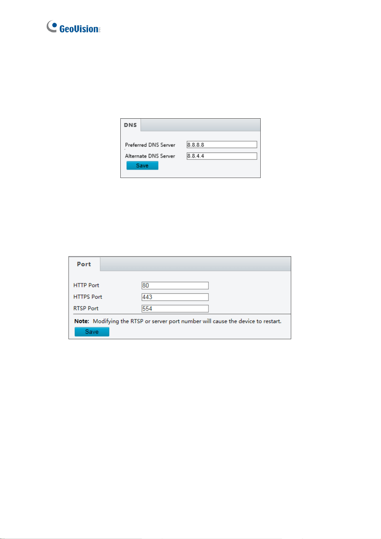
4.2.2 DNS
Type the camera’s Preferred DNS Server and Alternate DNS Server. For GV-SD2322-IR,
you can find the same setting in TCP / IP of the left menu.
Figure 4-5
4.2.2 Port
You can modify the default HTTP port, HTTPS port and RTSP port if necessary.
Figure 4-6
Administrator Mode
41
4
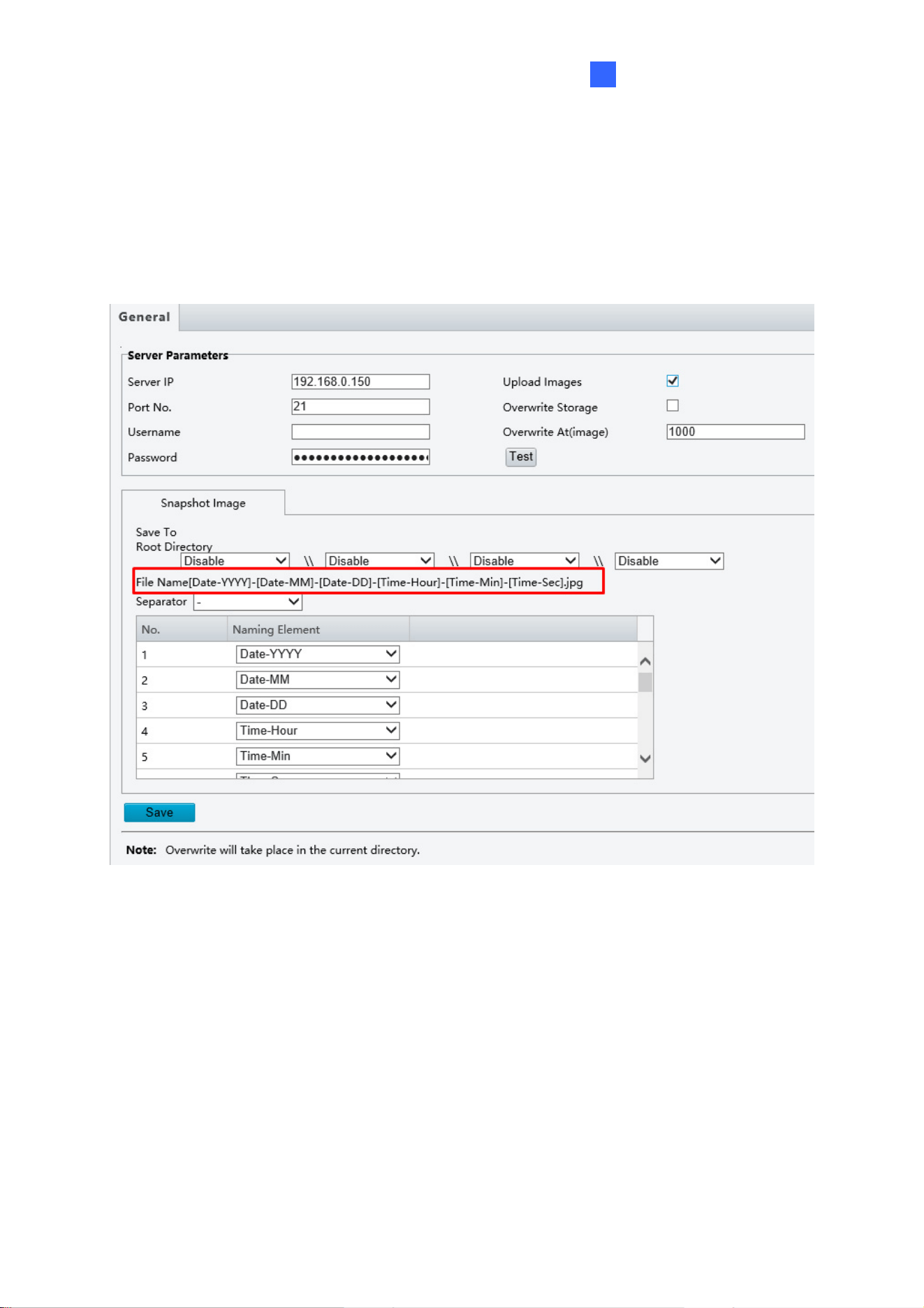
4.2.3 FTP
After the configuration of FTP, you will be able to upload snapshots from the camera to the
specified FTP server.
Figure 4-7
1. Type the Server IP address.
2. Change the Port No. of the FTP server if needed.
3. Type the Username and Password of the upload account.
4. Enable Upload Pictures / Upload Images.
42
Step 5, 6 and 7 are applicable only to GV-SD2722-IR / SD3732-IR:
5. select Overwrite Storage to overwrite the oldest images when the storage is full. You
can set the number of images in Overwrite At (Image). When the defined image
threshold is reached, the oldest images will be overwritten.
6. Save To Root Directory: Select a directory in which to save the images, or select
Custom to name a storage folder on the FTP server.
7. Under File Name, select a Separator and a combination of Naming Element(s) to name
the snapshots captured. A template of the file name is shown.
8. Click Save.
Note:
1. To upload snapshots, make sure to enable Capture / Snapshot in Video & Audio. For
more detailed instructions, refer to 4.3.3 Capture / Snapshot.
2. If Overwrite Storage is not selected and the storage is full, snapshots can no longer be
taken.
Administrator Mode
43
4
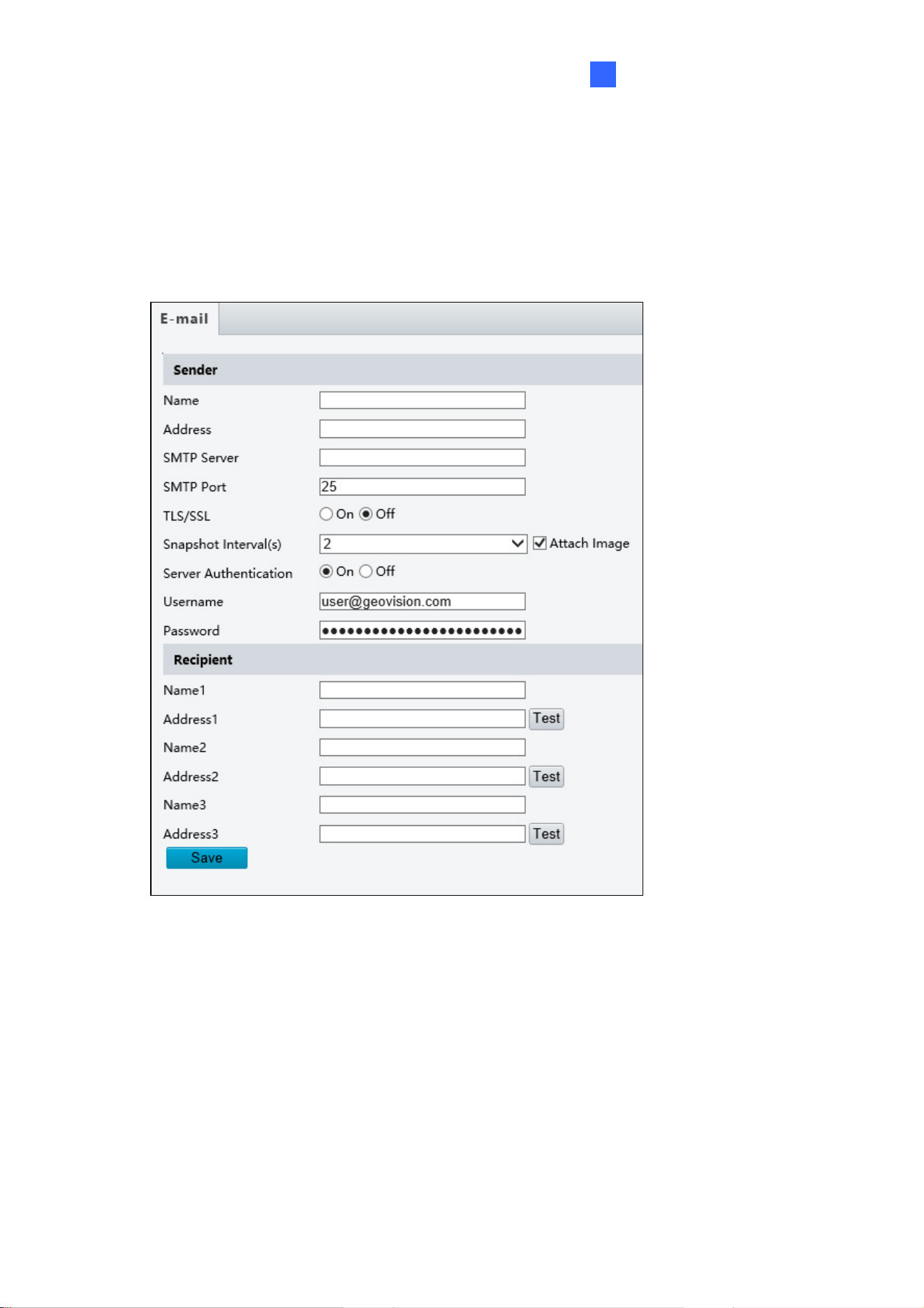
4.2.4 E-mail
After the configuration of E-mail, you will be able to send messages to the specified E-mail
address when alarms are triggered.
Figure 4-8
[Sender]
1. Type the Name and Address of the sender.
2. Type the SMTP Server.
3. Type the SMTP Port number.
4. To send the e-mail through TLS / SSL encryption, enable TLS / SSL.
5. Enable Attach Image to include 3 instant snapshots as attachment in the e-mail
according to the Capture Interval (s) / Snapshot Interval (s) specified.
6. If the SMTP Server needs authentication, enable Server Authentication and type a valid
username and password to log in the SMTP server.
44
[Recipient] Type the name and e-mail address of the recipient.
For GV-SD2722-IR / SD3732-IR, click the
button next to the address of a Recipient to
Test for the validity of the e-mail address.
Note: To send snapshots to the specified E-mail address, make sure to enable Capture /
Snapshot in Video & Audio. For more detailed instructions, refer to 4.3.3 Capture.
Administrator Mode
45
4
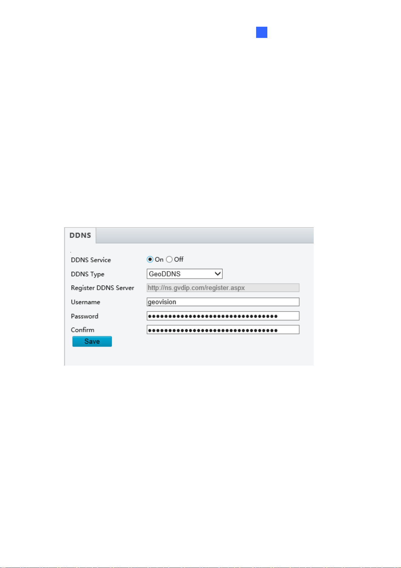
4.2.5 DDNS
Note this function is only applicable to GV-SD2722-IR / SD3732-IR.
DDNS (Dynamic Domain Name System) provides a convenient way of accessing the camera
when using a dynamic IP. DDNS assigns a domain name to the camera, so that the
Administrator does not need to go through the trouble of checking if the IP address assigned
by DHCP Server or ISP (in xDSL connection) has changed.
Before enabling the DDNS function, the Administrator should apply for a Host Name from the
DDNS service provider’s website. There are 2 providers listed in the camera: GeoVision
GVDIP, GeoVision DDNS Server and DynDNS.org.
Figure 4-9
1. Click On to enable DDNS Service.
2. Select the DDNS service provider you have registered with. If you chose DynDNS, skip to
Step 5.
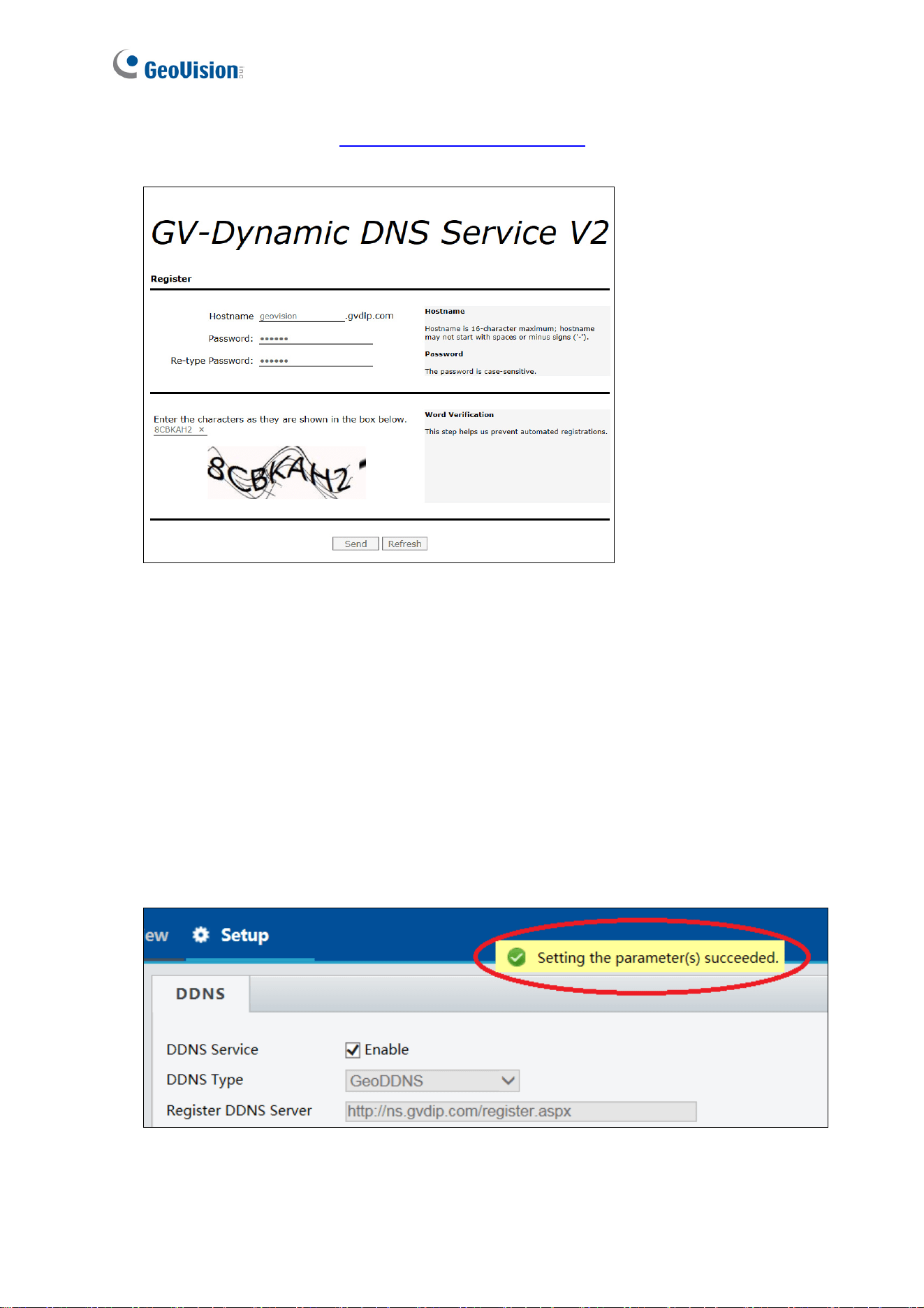
46
3. Copy the website address
http://ns.gvdip.com/register.aspx
to a browser to access
Geovision DDNS service.
Figure 4-10
4. In the Geovision DDNS Server page, type a desired Hostname and Password. Re-type
Password and type the verification letters shown in the image. Click Send.
5. In the Web interface of your camera, type Username. The username is the hostname
registered in DDNS Server.
6. Type Password, and Confirm Password.
7. Click Save.
After the DDNS is successfully configured, a notification bar will be displayed as shown in
Figure 4-11. Next time when you want to log in the camera, type the domain name like this:
(hostname).gvdip.com, for example, geovision.gvdip.com.
Figure 4-11
Administrator Mode
47
4
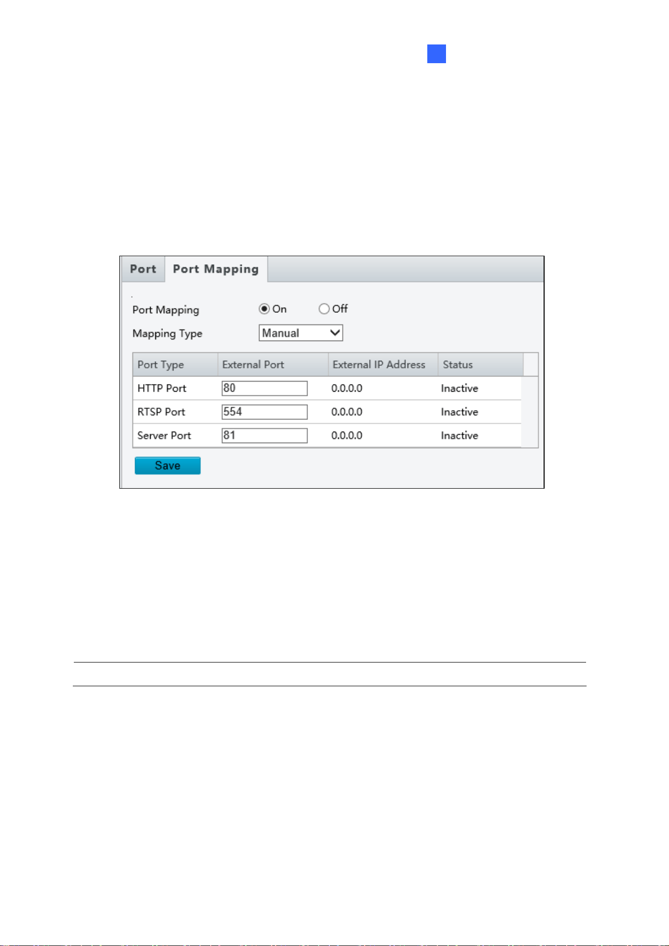
4.2.6 Port Mapping
Note this function is only applicable to GV-SD2722-IR / SD3732-IR.
This function can automatically forward and open certain ports on your router, allowing
connection to your camera from the Internet.
Figure 4-12
1. Enable Port Mapping, and select Mapping Type.
2. If you select Automatic, external ports will be automatically configured by the router.
3. If you select Manual, configure the external ports. External IP is applied to the camera
automatically. If the configured port is occupied, the Status will show inactive.
4. Click Save.
Note: For this function, your router needs to support port forwarding.
48
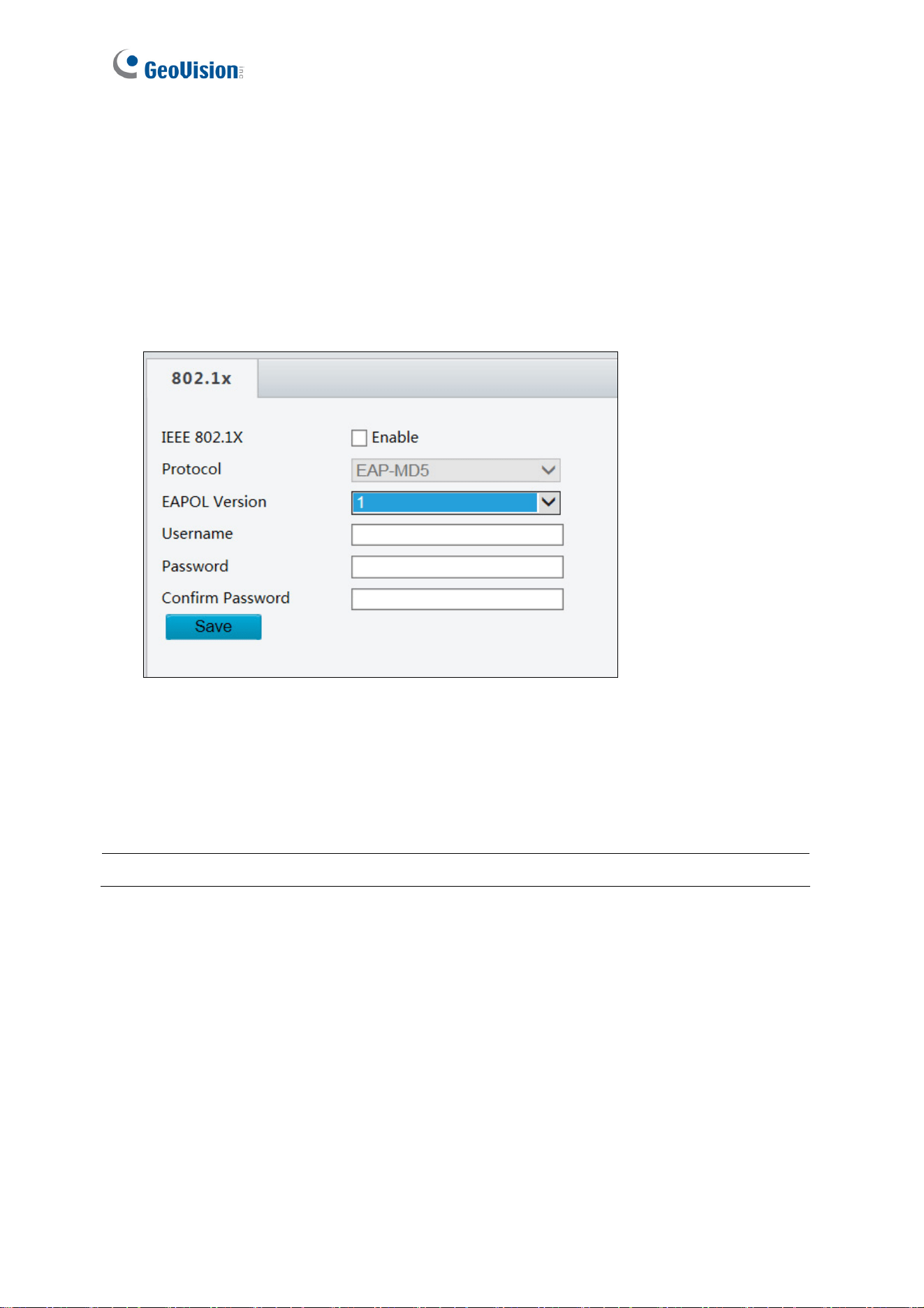
4.2.7 802.1x
Note this function is only applicable to GV-SD2722-IR / SD3732-IR.
IEEE 802.1x is an IEEE standard for port-based Network Access Control. It provides an
authentication mechanism to devices connecting to a LAN or WLAN.
Figure 4-13
1. Enable IEEE 802.1x.
2. Type the Username and Password. Type the password again for confirmation.
3. Click Save.
Note: For this function, your network environment needs to support 802.1x.
Administrator Mode
49
4
4.3 Video & Audio
This section allows you to configure the three video streams, as well as audio settings.
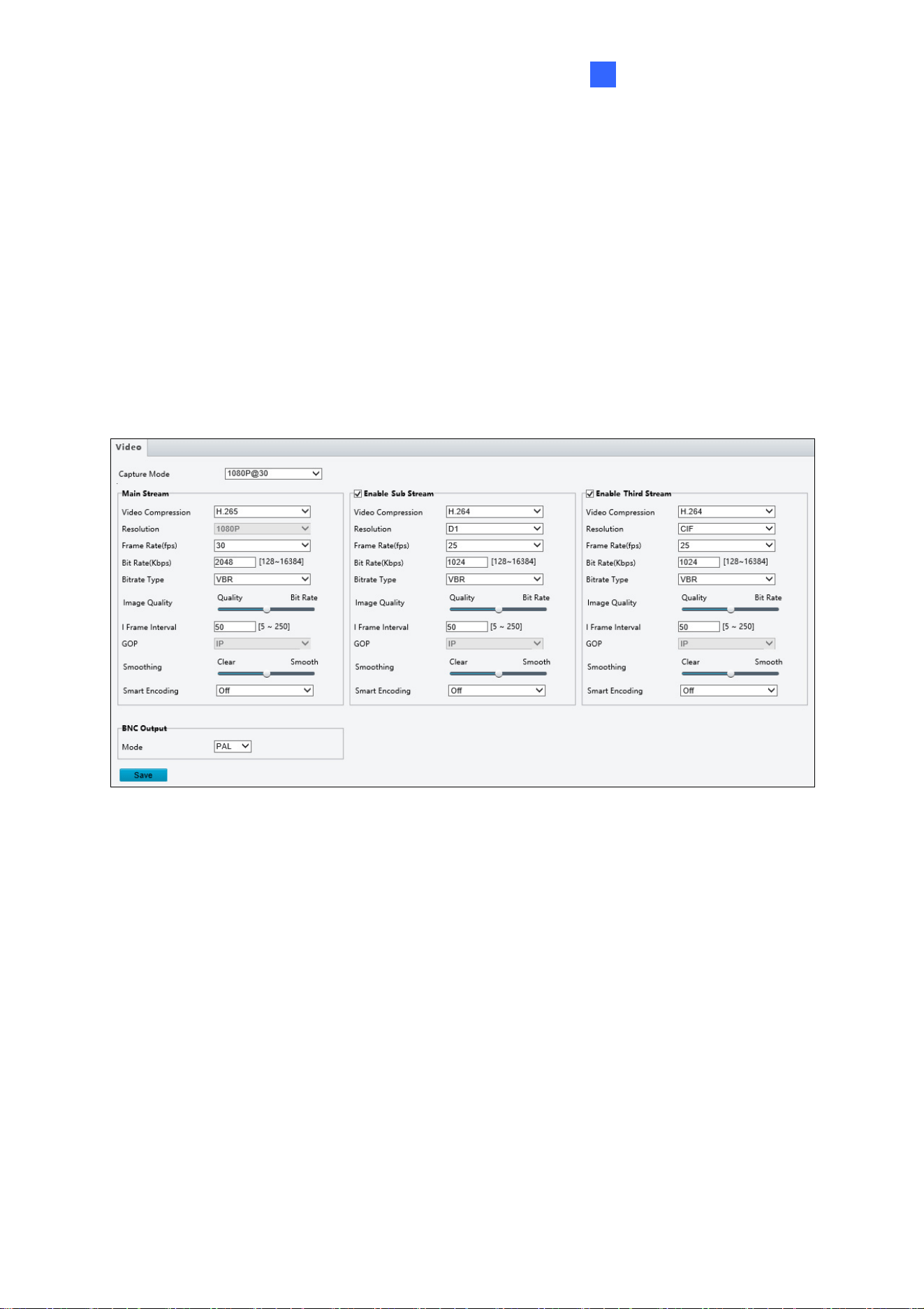
4.3.1 Video
You can set video parameters that your camera supports and view the current status of BNC
output. You may also enable the sub-stream and third stream as needed.
Figure 4-14
Capture Collect Mode: Sets the maximum resolution and frame rate.
The following options are available for the main, sub and third streams.
Video Compression: Set the codec type to H.264 or MJPEG (for GV-SD2322-IR), or to
H.265, H.264 or MJPEG (for GV-SD2722-IR / SD3732-IR).
Resolution: You may select the different resolutions for each stream.
Frame Rate: Select a frame rate for encoding images. The unit is frame per second.
Bit Rate:
CBR: The camera transmits data at a constant data rate by varying the quality of the
stream
VBR: The quality of the video stream is kept as constant as possible at the cost of a
varying bitrate.

50
Image Quality: When VBR is selected for the encoding mode, you can move the slider
to adjust quality level for images. Moving the slider toward Bit Rate decreases the bit
rate and may affect image quality. Moving the slider toward Quality increases the bit
rate and improves image quality.
I Frame Interval: Set the number of frames between each I frame (key frame). This
option is only available when H.265 or H.264 is selected for codec.
Smoothing: Set the extent of smoothing. Choosing Clear disables Smoothing. Moving
the slider toward Smooth increases the level of smoothing but will affect image quality.
Smart Encoding: Reduce the bitrate for smoother transmission. Choosing Basic Mode
disables I Frame Interval and Smoothing.
[BNC Output] The status of the BNC device is shown.
Mode: Set the signal format of the video output to either NTSC or PAL.
Administrator Mode
51
4
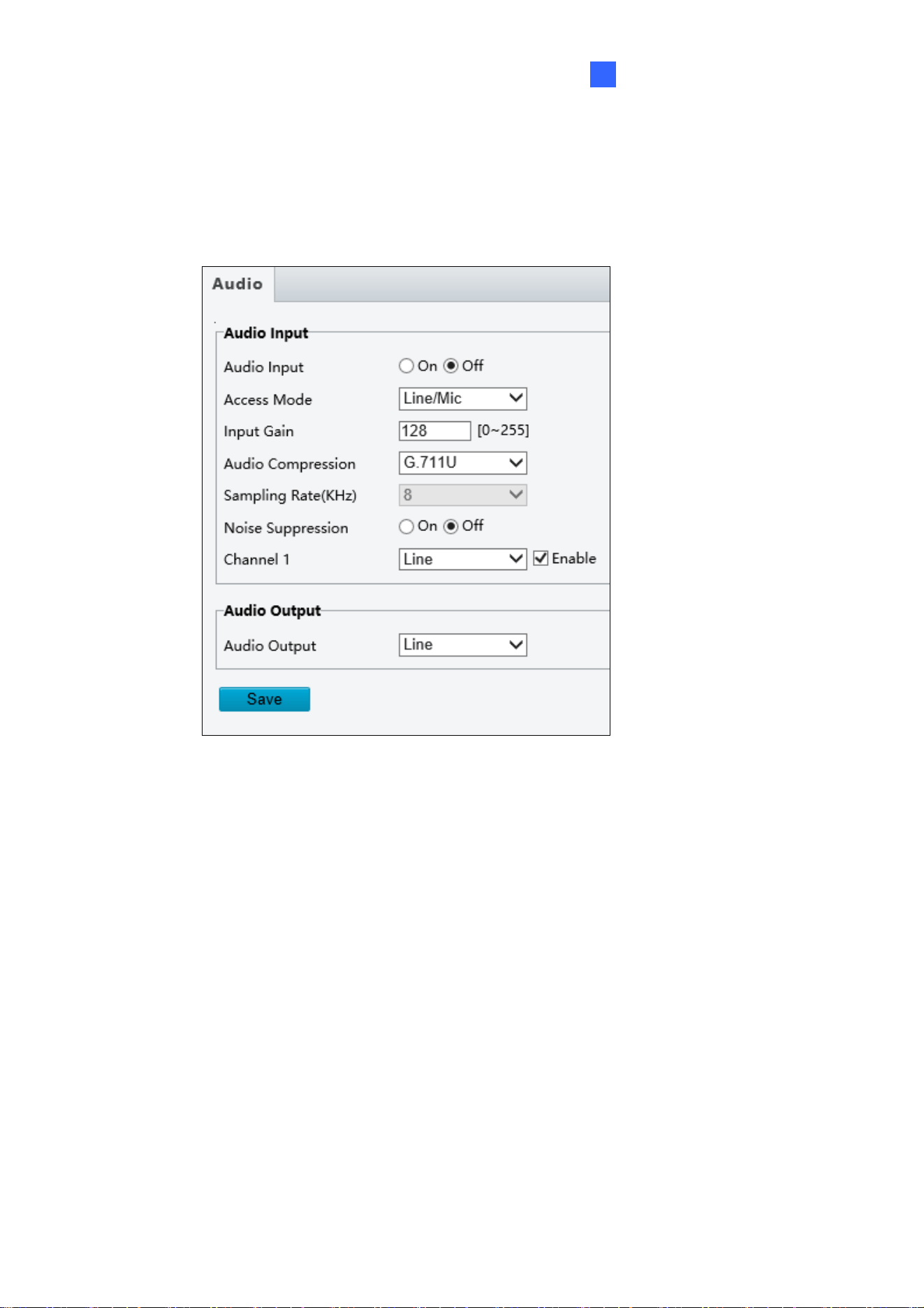
4.3.2 Audio
You can configure the audio settings of the camera.
Figure 4-15
The following options are available.
Audio Input: Select ON to enable audio input.\
Input Gain: Set the audio signal amplification for sampling. The greater the gain, the
greater amplification
Audio Compression: Select an audio codec.
The functions below are only applicable to GV-SD2722-IR / SD3732-IR.
Noise Suppression: Select On to reduce the noise of the audio.
Channel 1: Click Enable to enable audio in through the camera’s built-in microphone.
Audio Output: Select the source of audio output.
52
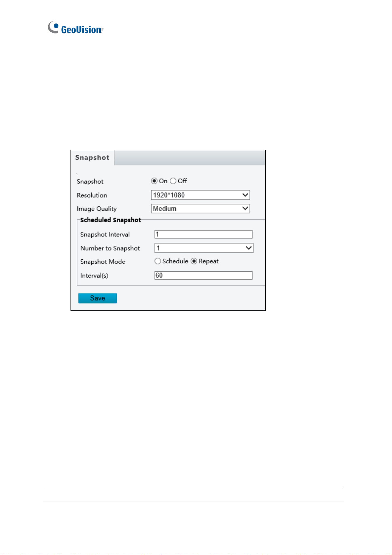
4.3.3 Capture / Snapshot
Note this function is only applicable to GV-SD2722-IR / SD3732-IR.
Using the Capture function, when an alarm is triggered, the camera will automatically upload
the captured snapshots to the FTP server or send snapshots to the specified e-mail address.
Figure 4-16
1. Enable Capture.
2. Select Resolution.
3. Choose the Image Quality.
4. Choose the Number (of snapshot) to Capture upon alarm trigger.
5. Only for GV-SD2722-IR / SD3732-IR, select Timed Mode / Schedule Mode or
Continued Mode / Repeat Mode to set up the Scheduled Snapshot.
6. If you select Timed mode / Schedule Mode, click + to specify a time to take a snapshot.
7. If you select Continued mode / Repeat Mode, type the interval in seconds to take a
snapshot.
8. Click Save.
Note: Capture Interval(s) is not functional.
Administrator Mode
53
4
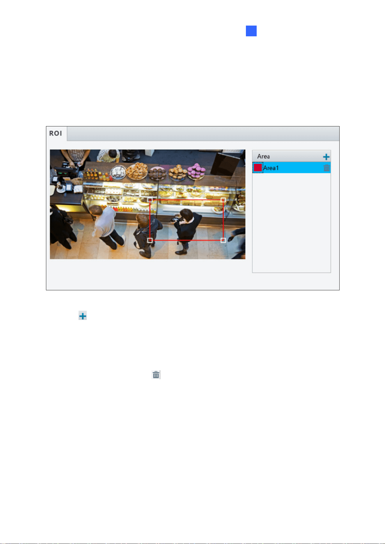
4.3.4 ROI
When Region of Interest (ROI) is enabled, the system ensures image quality for ROI first if
the bit rate is insufficient. Note this function is only applicable to GV-SD2722-IR / SD3732-IR.
Figure 4-17
1. Click
to enable and add ROI.
2. Click and drag on the image to specify an area.
3. To add additional ROI areas, repeat steps 1 and 2. Up to eight ROI areas can be
4. specified.
5. To delete an ROI area, click
.
54
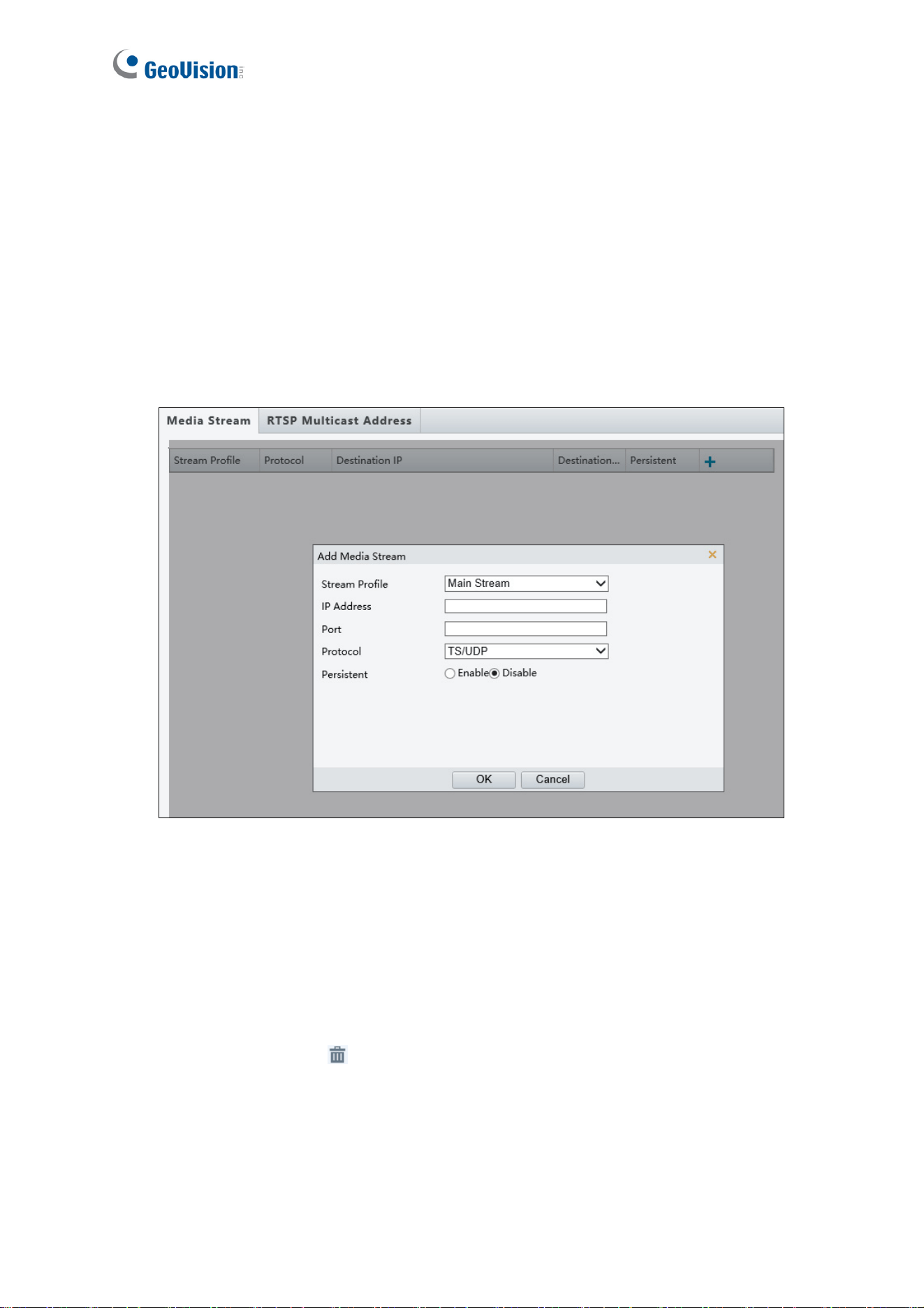
4.3.5 Media Stream
Note this function is only applicable to GV-SD2722-IR / SD3732-IR.
Media Stream
By configuring media stream, you can set the camera to transmit code streams by UDP or
TCP protocol to a specified IP address and port number. The settings can be saved and take
effect after the camera is restarted.
Figure 4-18
1. Click + and then select a type in the Stream Profile.
2. Type the IP Address and Port number of the unicast or multicast group for the decoding
device that receives audio and video streams from the camera.
3. If you want the device to establish the media stream that has been configured before
automatically after the restart, select Yes / Enable for Persistent.
4. To delete a stream, click
.
5. Click Submit to complete the settings.
Administrator Mode
55
4
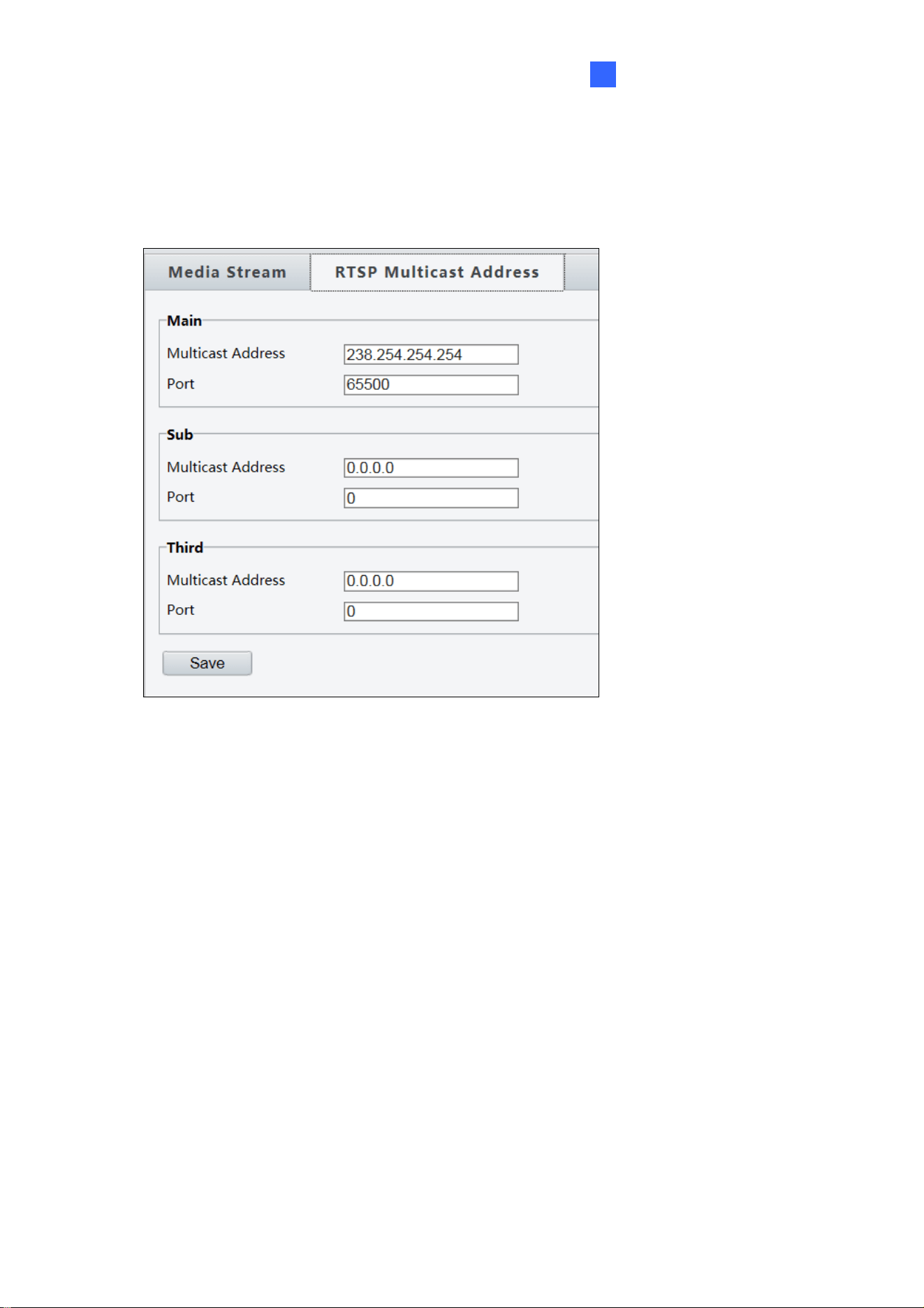
RTSP Multicast Address
After an RTSP multicast address is configured, the third-party player can request the RTSP
multicast media stream from the camera through the RTP protocol.
Figure 4-19
1. Type the Multicast Address (224.0.0.0 to 239.255.255.255) and Port number (0 to
65535).
2. Click Save.
For RTSP Multicast command, see Appendix A.
.
56
4.4 PTZ
4.4.1 Home Position
You can set the camera to return to home position if no operation is made within a specified
period. For detailed instructions, refer to 3.2 Setting Home Position.
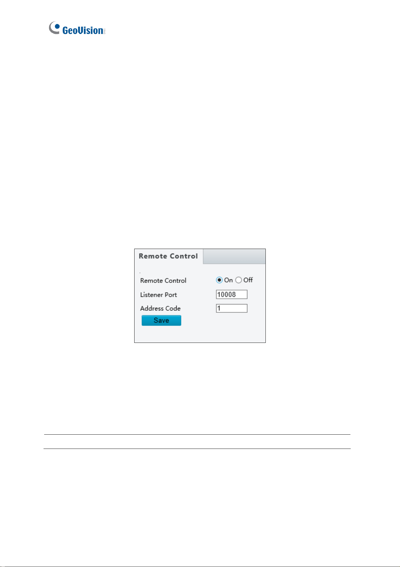
4.4.2 Remote Control
Note this function is only applicable to GV-SD2722-IR / SD3732-IR.
You can connect a third-party PTZ remote control program to your GV-IP Speed Dome once
this function is enabled.
Figure 4-20
1. Specify the Listener Port to which the third-party PTZ remote control program connects.
2. Assign an individual Address Code (between 0 ~ 255) to each PTZ remote control
program
3. Click Save.
Note: For this function, your router needs to support port forwarding.
Administrator Mode
57
4
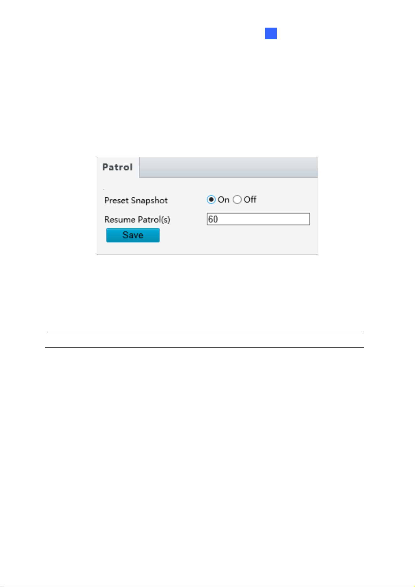
4.4.3 Patrol
Note this function is only applicable to GV-SD2722-IR / SD3732-IR.
You can set the camera to take a snapshot and upload the image to the FTP server when
the camera goes to the preset during the patrol route.
Figure 4-21
1. Enable Preset Snapshot.
2. Type the Resume Patrol(s) interval in seconds to upload snapshots.
3. Click Save.
Note: For this function, make sure to configure the settings in 4.2.3 FTP first.
58
4.5 Image
This section introduces the Image Settings, On-screen Display, and Privacy Mask.
4.5.1 Image
This page allows you to adjust image settings such as brightness, exposure, IR illumination
and white balance.
Figure 4-22
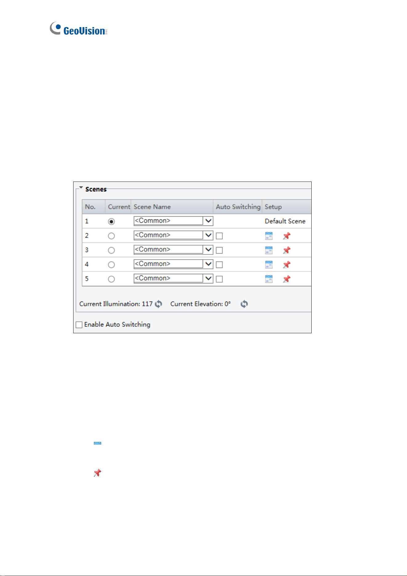
[Scene]
Current: Indicates the scene that is being used.
Screen Name: When you select a scene, the corresponding image parameters are
displayed. You can adjust image settings according to actual needs.
Auto Switching: Indicates whether to add a scene to the auto-switching list.
Setup:
Click
to set a schedule for auto-switching, including schedule, illumination, and
current elevation (angle between the PTZ and the horizontal direction).
Click
to set a scene as the default scene.
Enable Auto Switching: Allow the camera can switch to the scene automatically when
the condition for switching to a non-default scene is met.
Administrator Mode
59
4
Figure 4-23
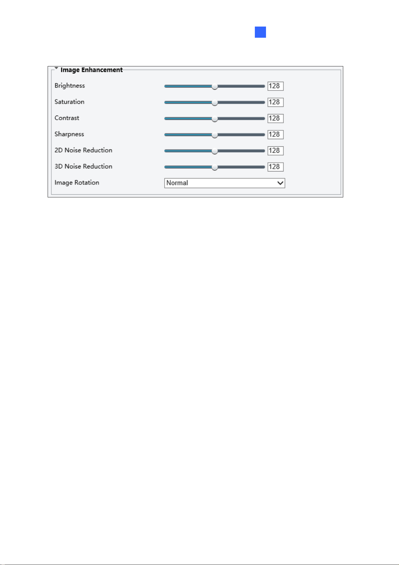
[Image Enhancement]
Brightness: Adjust the degree of brightness of the image.
Saturation: Adjust the amount of a hue contained in a color.
Contrast: Set the degree of difference between the blackest pixel and the whitest pixel.
Sharpness: Adjust the sharpness of the image.
2D / 3D Noise Reduction: Reduce the noise of the image.
Image Rotation: Change the rotation of the image.
60
Figure 4-24
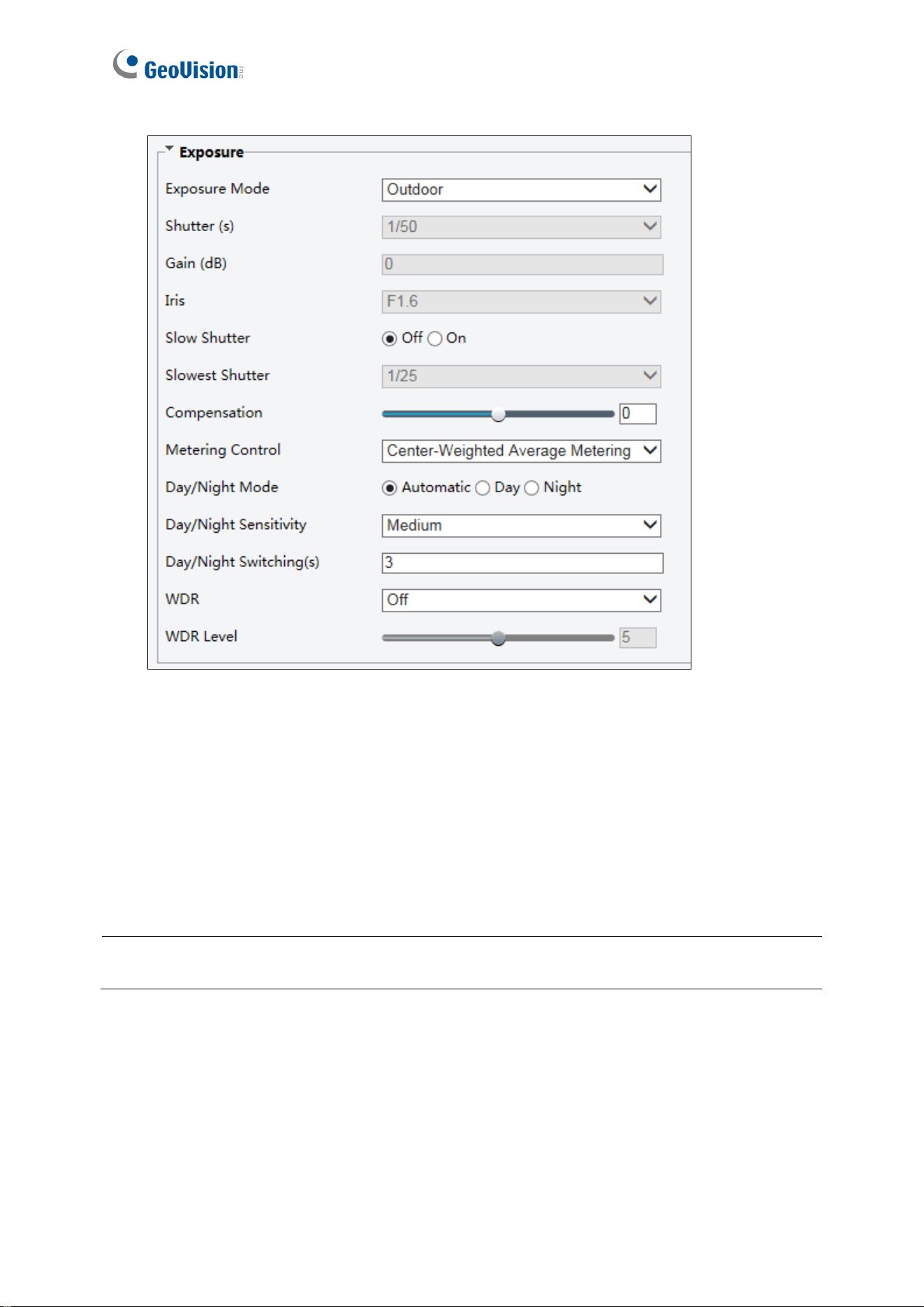
[Exposure]
Exposure Mode: Select the correct exposure mode to achieve the desired exposure
effect. The default setting is Outdoor with a frequency of 50 Hz.
Shutter (s): The length of time that allows light to enter into the lens. You can set a
shutter speed when Exposure Mode is set to Manual (Custom) or Shutter Priority.
Note: If Slow Shutter is set to Off, the reciprocal of the shutter speed must be greater than
the frame rate.
Gain (dB): Control image signals so that the camera outputs standard video signals
according to the light condition. You can set this parameter only when Exposure Mode
is set to Manual (Custom) or Gain Priority.
Iris: Sets the aperture size of the lens. This function is only applicable to GV-SD2322-IR.

Administrator Mode
61
4
Slow Shutter: Improve image brightness in low light conditions. For GV-SD2322-IR,
you can only set this parameter when Exposure Mode is not set to Shutter Priority
and when Image Stabilizer is disabled.
Slowest Shutter: Set the slowest shutter speed that the camera can use during
exposure.
Compensation: Adjust the compensation value as required to achieve the desired
effects. You can set this parameter only when Exposure Mode is not set to
Manual (Custom).
Metering Control: Set the way the camera measures the intensity of light. You can only
set this parameter when Exposure Mode is not set to Manual (Custom).
Center-Weighted Average Metering: Measure light mainly in the central part of
images.
Evaluative Metering (BLC): Measure light in the customized area of images.
Face Metering: Measure light where facial recognition is established.
Spot Metering: Measure light spot(s) in the specified area of the images.
Highlight compensation: Ignore the brightness of the overexposed area of images.
But selecting this setting will decrease the overall brightness of the image This
function is applicable only to GV-SD2322-IR.
Day/Night Mode: Select Automatic for automatic switch between day mode and night
mode depending on the amount of light detected. Select Night to produce high-quality
black and white images using the existing light. Select Day to produce high-quality color
images using the existing light.
Day/Night Sensitivity: Set the light threshold for switching between day mode and
night mode. A higher sensitivity means that the camera is more sensitive to the change
of light and becomes more easily to switch between day mode and night mode.
Day/Night Switching(s): Set the length of time before the camera switches between
day mode and night mode after the conditions for switching are met.
WDR: Enable WDR to distinguish the bright and dark areas in the same image.
WDR Level: After enabling the WDR function, you can improve the image by adjusting
the WDR level.
Suppress WDR Stripes:
Enable Suppress WDR Stripes to automatically adjust shutter
frequency based on the frequency of light measured.
62
Figure 4-25
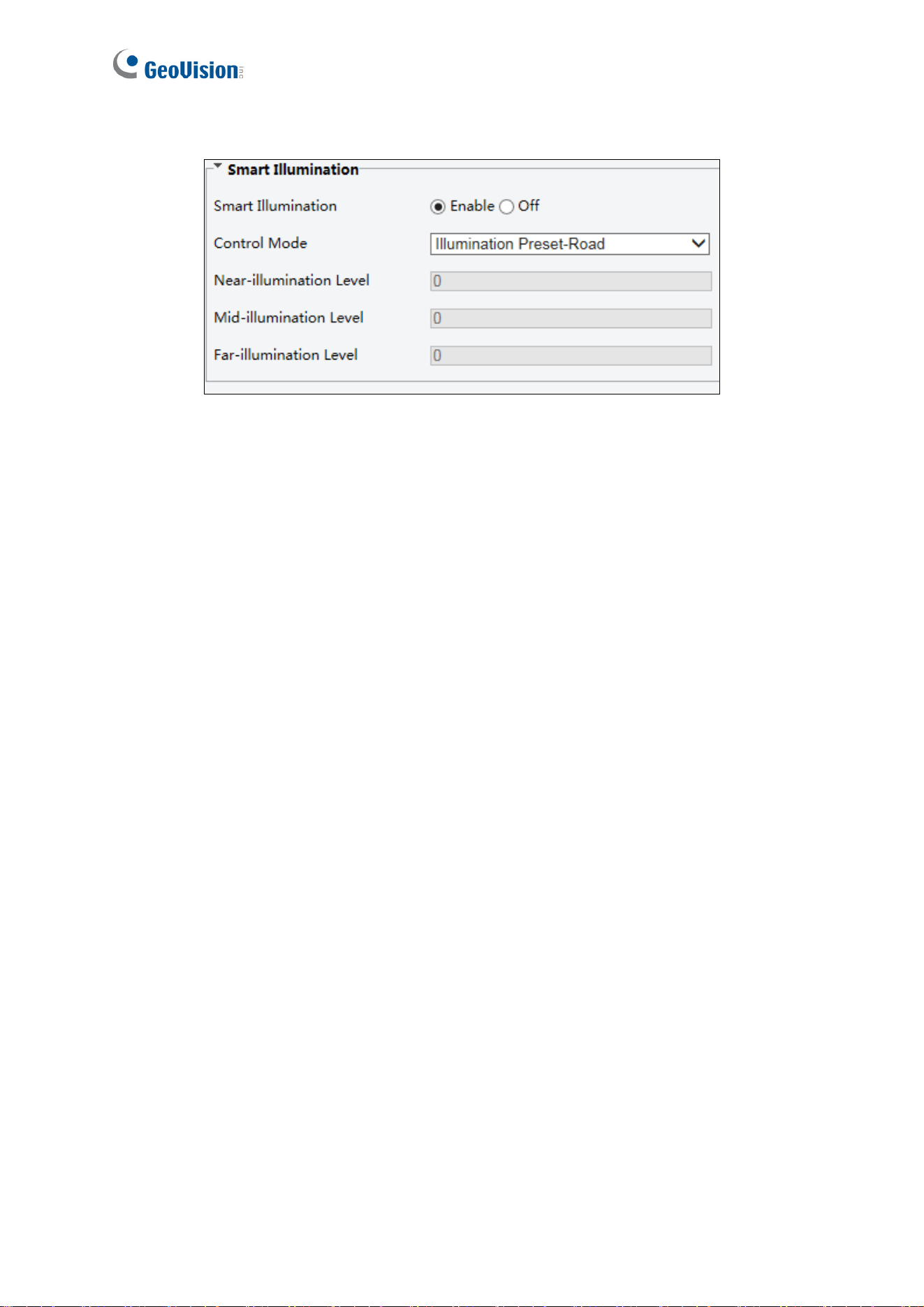
[Smart Illumination]
Smart Illumination: Select Enable to adjust the IR illumination settings.
Control Mode:
Global Mode: (The function is only applicable to GV-SD2322-IR.) Adjust IR
illumination and exposure to achieve balanced image effects. Some areas might be
overexposed if you select this option. This option is recommended if monitored
range and image brightness are your first priority.
Overexposure Restrain: (The function is only applicable to GV-SD2322-IR.) Adjust
IR illumination and exposure to avoid regional overexposure. Some areas might be
dark if you select this option. This option is recommended if clarity of the central part
of the image and overexposure control are your first priority.
Illumination Preset-Road / Road: Offer strong illumination in whole and is
recommended for monitoring wide-ranging scenes, for example, road.
Illumination Preset-Park / Park: Offer uniform light and is recommended for
monitoring small range scenes with many obstacles, for example, industrial parks.
Manual: (The function is only applicable to GV-SD2322-IR.) Allow you to manually
control the intensity of IR illumination.
Illumination Level: Set the intensity level of the IR light. The greater the value, the
higher the intensity. 0 means that the IR light is turned off. When Control Mode is set to
Manual, you can set the intensity level of the IR light.
Administrator Mode
63
4
Figure 4-26
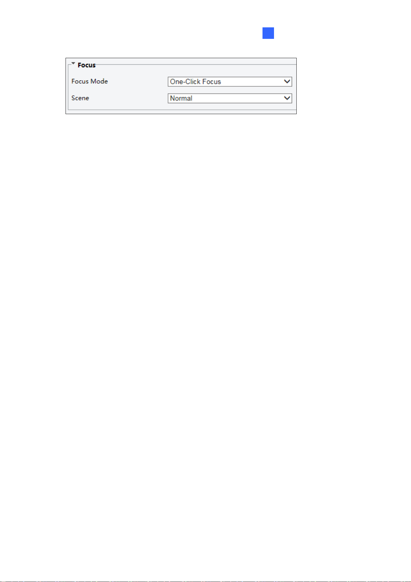
[Focus]
Focus Mode:
Auto Focus: Focuses automatically according to the current light condition.
Manual Focus: Manually adjust camera focus as required.
One-Click Focus: The camera is triggered to focus once when rotating, zooming or
going to a preset.
One-Click Focus (IR): In a low light condition such as during night hours or in a dark
house, this focus mode achieves better effects with the IR light turned on.
Scene:
Normal: Used for common scenes, such as road and industrial park.
Long distance: Used for long-distance monitoring on a road.
64
Figure 4-27
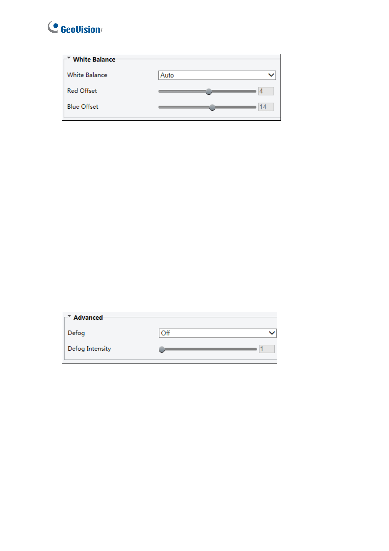
[White Balance]
White Balance: Adjust the red or blue offset of the image.
Auto: Adjust the red and blue offset automatically according to the light condition
(the color tends to be blue).
Outdoor: (The function is only applicable to GV-SD2722-IR / SD3732-IR). It is
recommended for outdoor scenes with a wide range of color temperature variation.
Fine tune: Allow you to adjust the red and blue offset manually.
Sodium / Sodium Lamp: Adjust the red and blue offset automatically according to
the light condition (the color tends to be red).\
Locked: (The function is only applicable to GV-SD2722-IR / SD3732-IR). Lock the
current color temperature settings without adjustment.
Figure 4-28
[Advanced]
Defog: Select Digital (for GV-SD2322-IR) or ON (for GV-SD3732-IR) to activate the
slider for adjusting the defog intensity for images.
Image Stabilizer: Enable EIS (Digital Image Stabilization).
Administrator Mode
65
4
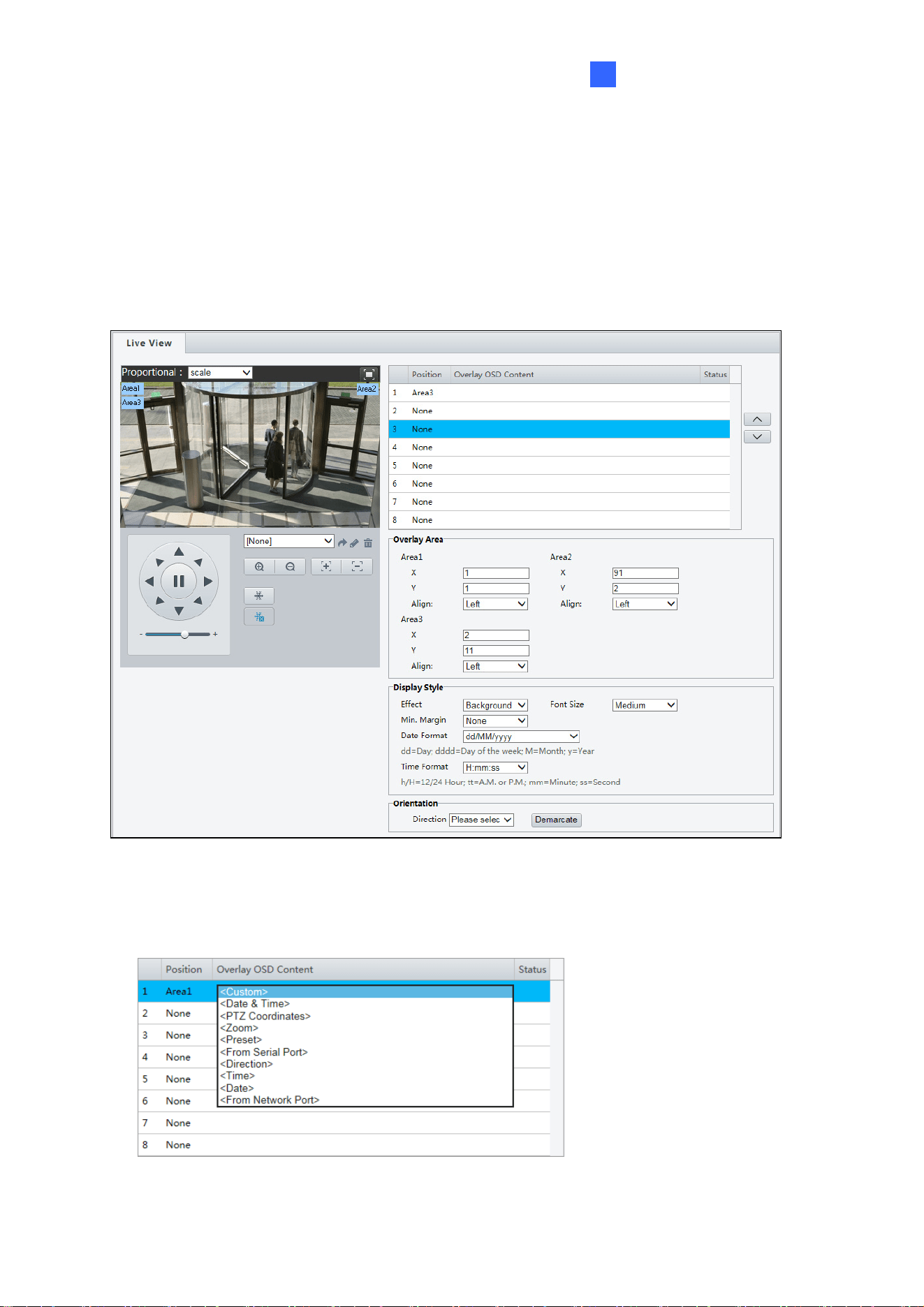
4.5.2 OSD
On Screen Display (OSD) is the text displayed on the screen with video images and may
include time and other customized contents.
For GV-SD2322-IR
Figure 4-29
1. Click under Position to select an Area #, and then click Overlay OSD Content to select
the content to display on screen.
Figure 4-30
66
2. Adjust the position of the Area 1/2/3 boxes on the live view either by dragging directly or
by specifying the coordinates under Overlay Area.
3. Under Display Style, customize the text style and date/time format.
4. Under Orientation, use the Direction drop-down list to select a direction, turn the
camera toward the corresponding direction, and click Demarcate.
After you have set the position and OSD content, the
symbol appears in the Status
column, which means that the OSD is set successfully. You may set multiple lines of
contents for each area and use
and to adjust the sequence of display.
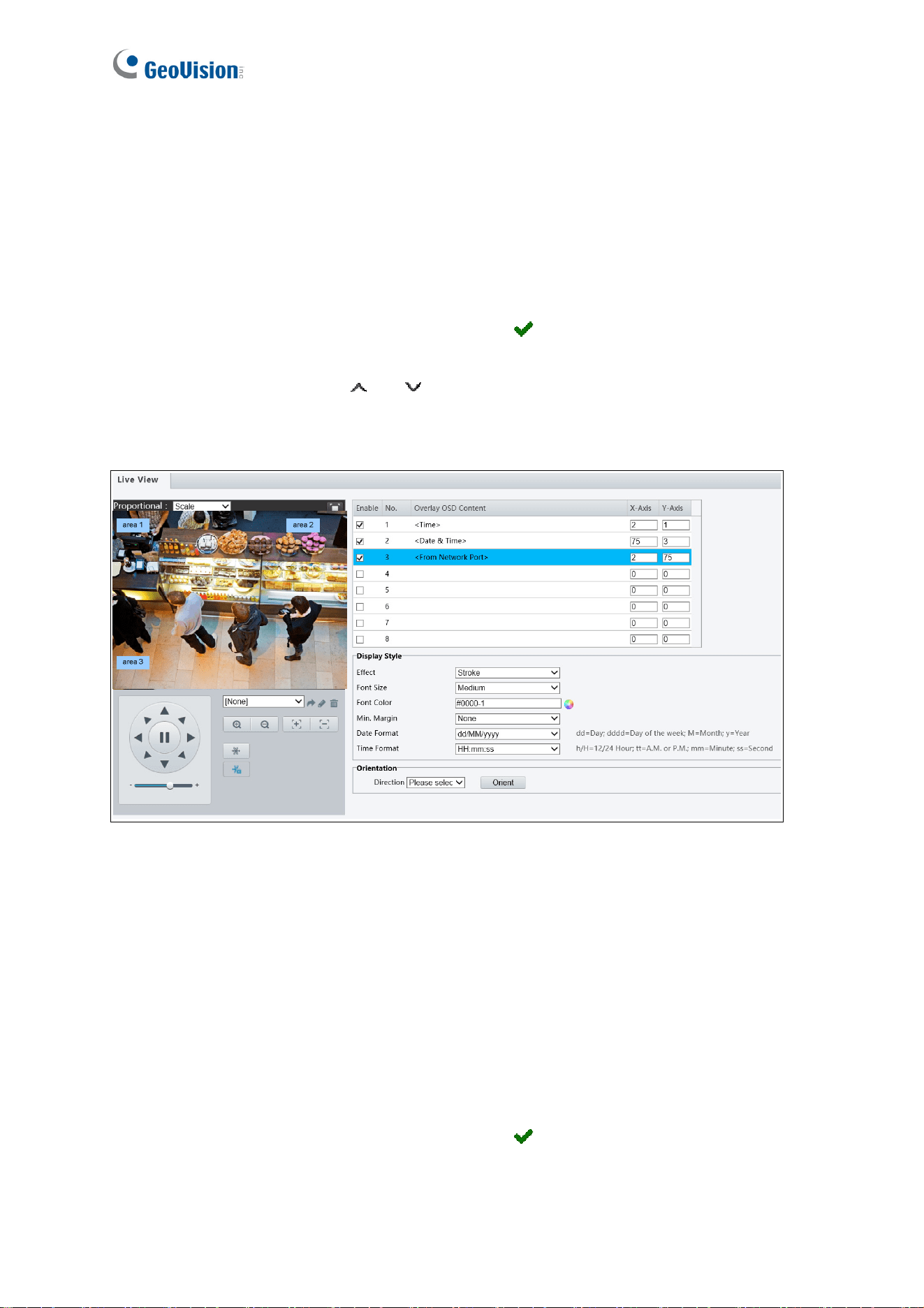
For GV-SD2722-IR / SD3732-IR
Figure 4-31
1. Enable a No. to select an area #, and then click Overlay OSD Content to select the
content to display on screen.
2. Adjust the position of the Area 1/2/3 boxes on the live view either by dragging directly or
by specifying the coordinates under the X-Axis / Y-Axis column.
3. Under Display Style, customize the text style and date/time format.
4. Under Orientation, use the Direction drop-down list to select a direction, turn the
camera toward the corresponding direction, and click Orient.
After you have set the position and OSD content, the
symbol appears in the Status
column, which means that the OSD is set successfully.
Administrator Mode
67
4
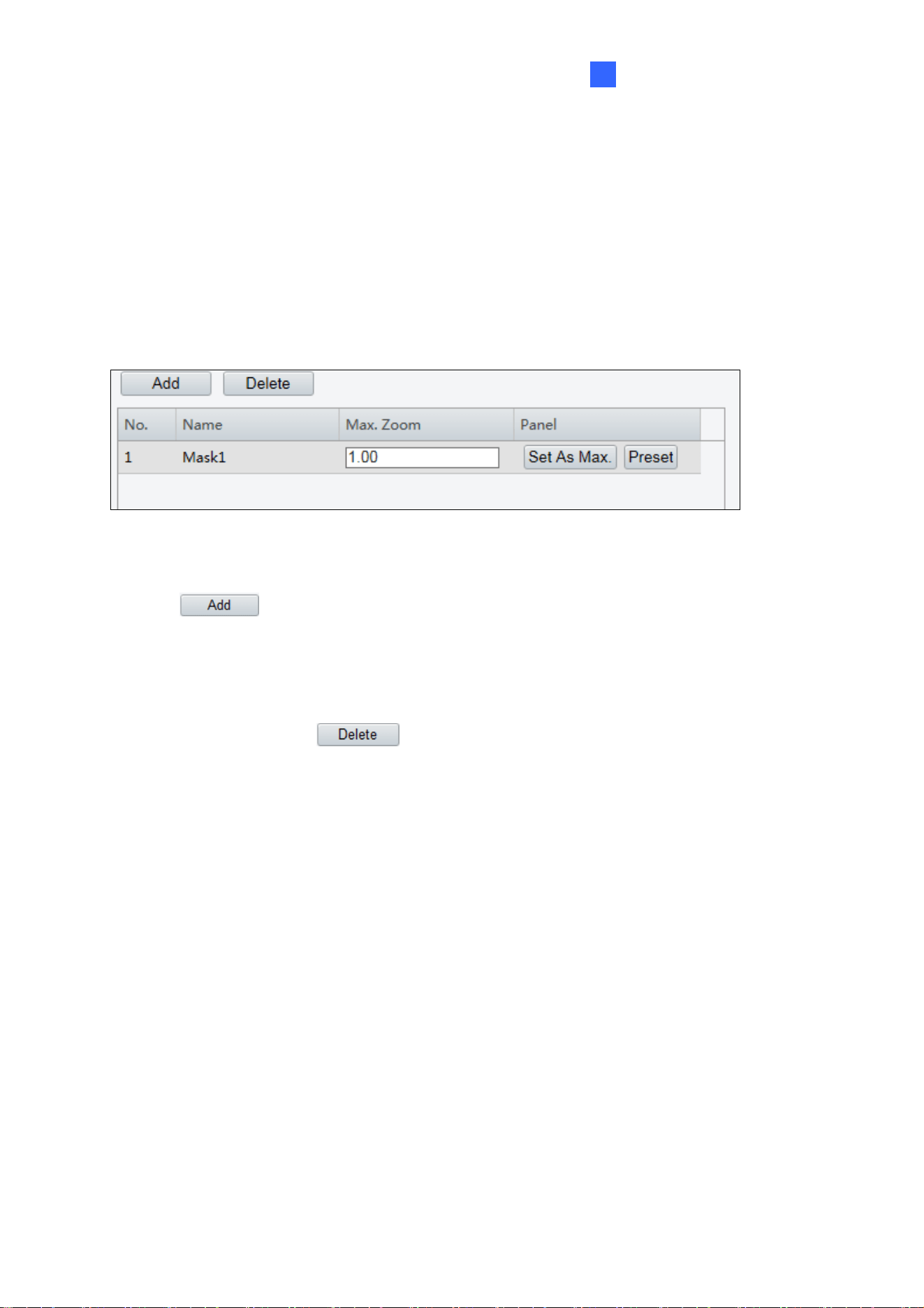
4.5.3 Privacy Mask
On certain occasions, you may need to set a mask area to block out parts of the camera
image to protect privacy, for example, the keyboard of an ATM machine. When PTZ changes
its position or zooms, the Privacy Mask will be adjusted accordingly to protect the area all
along.
Figure 4-32
1. Click
to add a privacy mask.
2. Click the box (with Mask displayed on it) to activate the mask.
3. Drag the box to the intended position and adjust the size of the box. Alternatively, you
can also use the mouse to draw a box on the area you want to mask.
4. To delete a mask, click
.
To quickly locate a mask on the camera view, select a mask and click Preset to turn the
camera toward the masked area. If the masked area is small, you can zoom in to the
appropriate level, and click Set as Max to mark the zoom level for future reference.

68
4.6 Intelligent
Note this function is only applicable to GV-SD2722-IR / SD3732-IR.
The Intelligent functions allow the camera to track moving people in a predefined area and
trigger warnings when the person trespasses a detection threshold, or attempts to breach
into a detection zone you set up.
Enabling the Auto Tracking function causes other Intelligent functions to be disabled and
vice versa.
4.6.1 Recommended Scenario
To achieve optimal tracking results, it is recommended to firmly install the camera at a
certain height in an open space. It is also essential to arrange proper lighting conditions to
avoid high contrast and backlighting that obscures the target. Below is the recommended
installation scenario:
Location: Install the camera in an open space with a clear view, such as a mall.
Height: Install the camera at 6 ~ 10 meters (19.7 ~ 32.8 ft.) above the ground.
Illumination: It is recommended to apply the Intelligent functions only when and
where there’s sufficient lighting.
There are certain limitations that causes ineffective tracking:
Number of the targets: The camera can only track one person at a time. When more
than one people walks into the detection area, only the first person entering the scene
is tracked. When the specified tracking time is over, the camera then continues to
track the second person.
Obstructions: When the target is blocked behind other objects while walking through
the detection zone during tracking, the target will be lost.
Administrator Mode
69
4
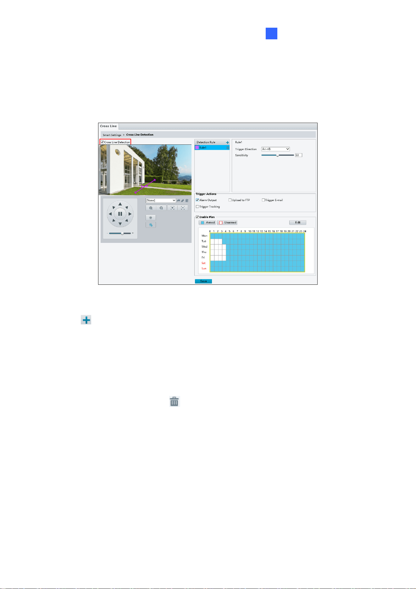
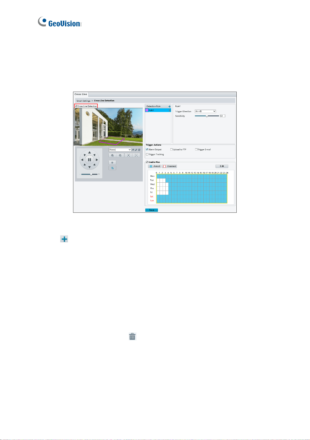
4.6.2 Cross Line
Cross line detection generates an alarm when a person walks past the detection threshold in
the direction you defined. Up to 4 detection lines can be added. Note that when adding
multiple detection lines, make sure they do NOT intersect as it may effect detection results.
AB
Figure 4-33
1. Enable Cross Line Detection.
2. Click
to add a detection line. Repeat this step to add another detection line.
3. Drag the ends of the detection line to the intended position to mark the detection
boundary.
4. Select the Trigger Direction, which will define the direction to trigger an alarm. For
example, if you choose A -> B, people moving from direction A to B will trigger an alarm.
5. You can move the slider to adjust detection Sensitivity.
6. To delete a detection line, click
For the settings on Trigger Actions and Enable Plan, see the same functions under
4.7.1 Motion Detection.
70
4.6.3 Intrusion
With Intrusion Detection, an alarm is generated when a person trespasses the boundaries of
the detection area. Up to 4 detection areas can be added. Note that is recommended NOT to
overlap the detection areas when adding multiple detection areas.
Figure 4-34
1. Enable Intrusion Detection.
2. Click
to mark the live view with new detection area. Repeat this step to add another
detection area.
3. Drag the nodes of the detection line to mark the boundary for detection.
4. You can use the following functions to reduce false alarm.
Time Threshold: The minimum period of time for a person to stay within the
detection area before an alarm is triggered.
Sensitivity: Move the slider to adjust the detection sensitivity.
Percentage: Type the minimum size of the person compared to the detection area
for the person to be detected.
5. To delete a detection area, click
For the settings on Trigger Actions and Enable Plan, see the same functions under
4.7.1 Motion Detection.
Administrator Mode
71
4
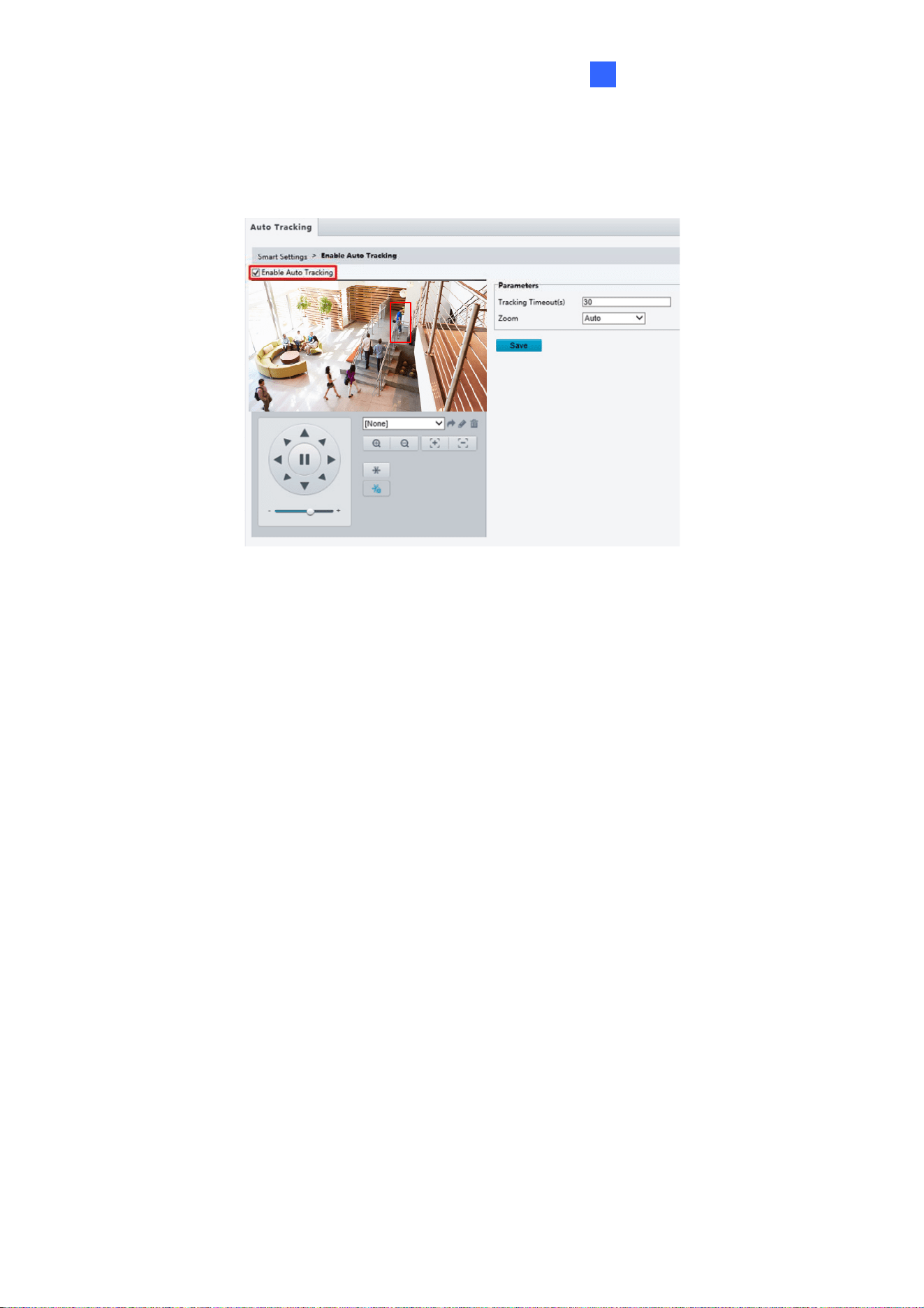
4.6.4 Auto Tracking
Auto Tracking allows you to track moving object(s) for as long as 300 seconds.
Figure 4-35
1. Enable Auto Tracking.
2. Type the amount of time for the camera to keep tracking moving objects in the Tracking
Timeout(s) field.
3. Select one of the following for Zoom.
Auto: The camera automatically zooms in on the moving objects upon tracking.
Current Zoom: The camera remains in its current zoom level when tracking moving
objects.
72
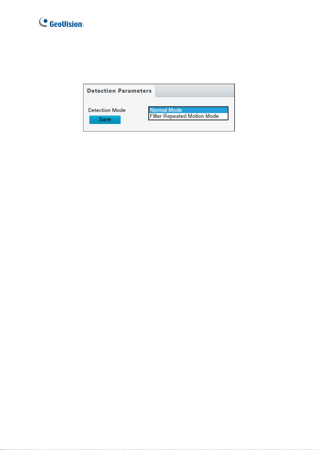
4.6.5 Advanced Settings
This section allows you choose between Normal Mode, which detects for moving targets
continuously, and Filter Repeat Motion Mode, which ignores repeated motions.
Figure 4-36
Administrator Mode
73
4
4.7 Events
You can set the camera to generate an alarm upon motion detection, temperature alarm,
audio alarm, and input trigger.
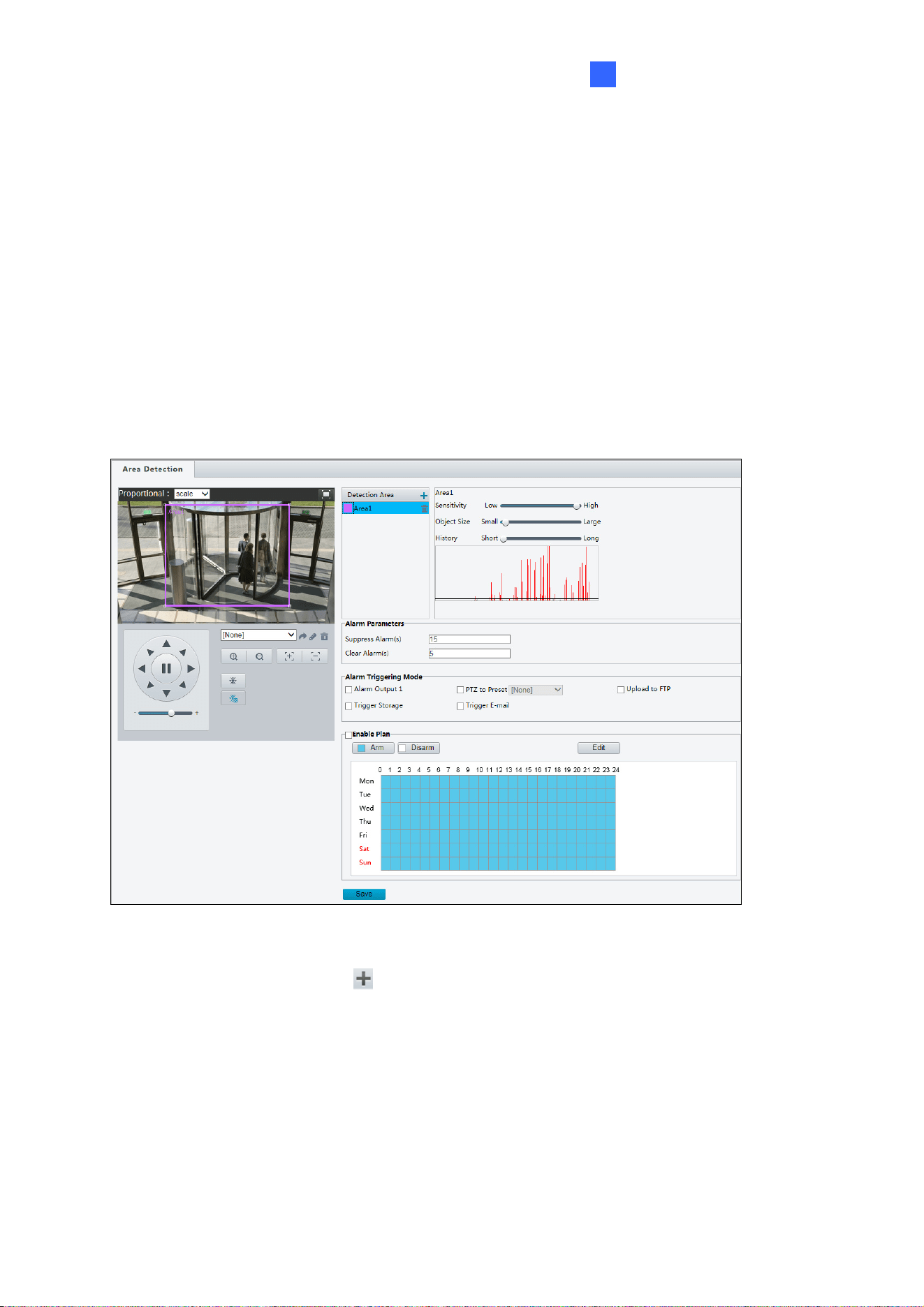
4.7.1 Motion Detection
Motion detection is used to generate an alarm whenever movement occurs in the specified
area.
Figure 4-37
1. In the Detection Area, click
to add a new detection area.
2. Click and drag the detection area to a desired location.
3. You can use the following functions to reduce false alarm.
Sensitivity: Moving the slider to the right increases detection sensitivity.
Object Size: When the extent of motion within the detection area exceeds the set
object size, motion detection alarm will be triggered.
History: (The function is only for GV-SD2322-IR.) If the duration of motion exceeds
the set duration motion detection alarm will be triggered.

74
Beneath History, motion detection results are shown in real time. The red lines represent
motion detection alarms. The longer a line, the greater the extent of motion.
[Alarm Parameters]
Suppress alarm: After an alarm is triggered, the same alarm will not be reported within
the set time.
Clear alarm: After an alarm is triggered,
If the same alarm is not triggered within the set time, the alarm will be cleared and
the same alarm can be reported again.
If the same alarm is triggered within the set time, the alarm will not be cleared until
the suppress alarm time expires. Then the same alarm can be reported again.
[Alarm Triggering Mode]
Alarm output 1: Select to trigger output upon motion detection.
PTZ to preset: Select to turn the camera to the selected preset point upon motion
detection.
Upload to FTP: Select to automatically upload snapshots to the specified FTP server
upon motion detection.
Trigger e-mail: Select to automatically send snapshots to the specified E-mail address
upon motion detection.
Trigger storage: Select to automatically start recording to the memory card upon
motion detection.
Note:
1. For the Upload to FTP function, make sure to configure the settings in 4.2.3 FTP and
4.3.3 Capture first.
2. For the Trigger e-mail function, make sure to configure the settings in 4.2.4 E-mail and
4.3.3 Capture first.
3. For the Trigger storage function, make sure to configure the settings in 4.8.1 Storage.
Administrator Mode
75
4
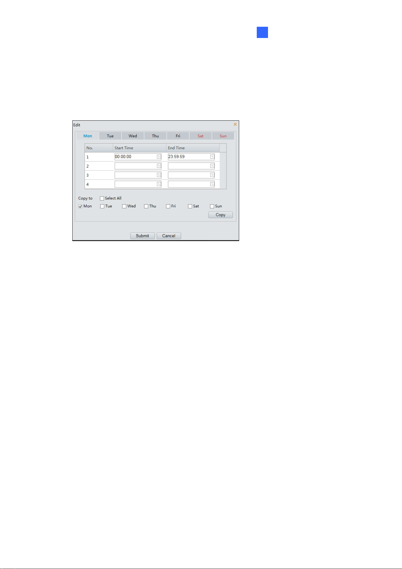
[Enable Plan]
Select this option to set the start and end times during which motion detection alarm is
enabled. You can directly drag the mouse to draw a plan or click Edit to edit time periods in
the table. You can set up to four periods for each day, and the time periods cannot overlap.
The camera reports alarms during the specified period(s) only.
Figure 4-38
76
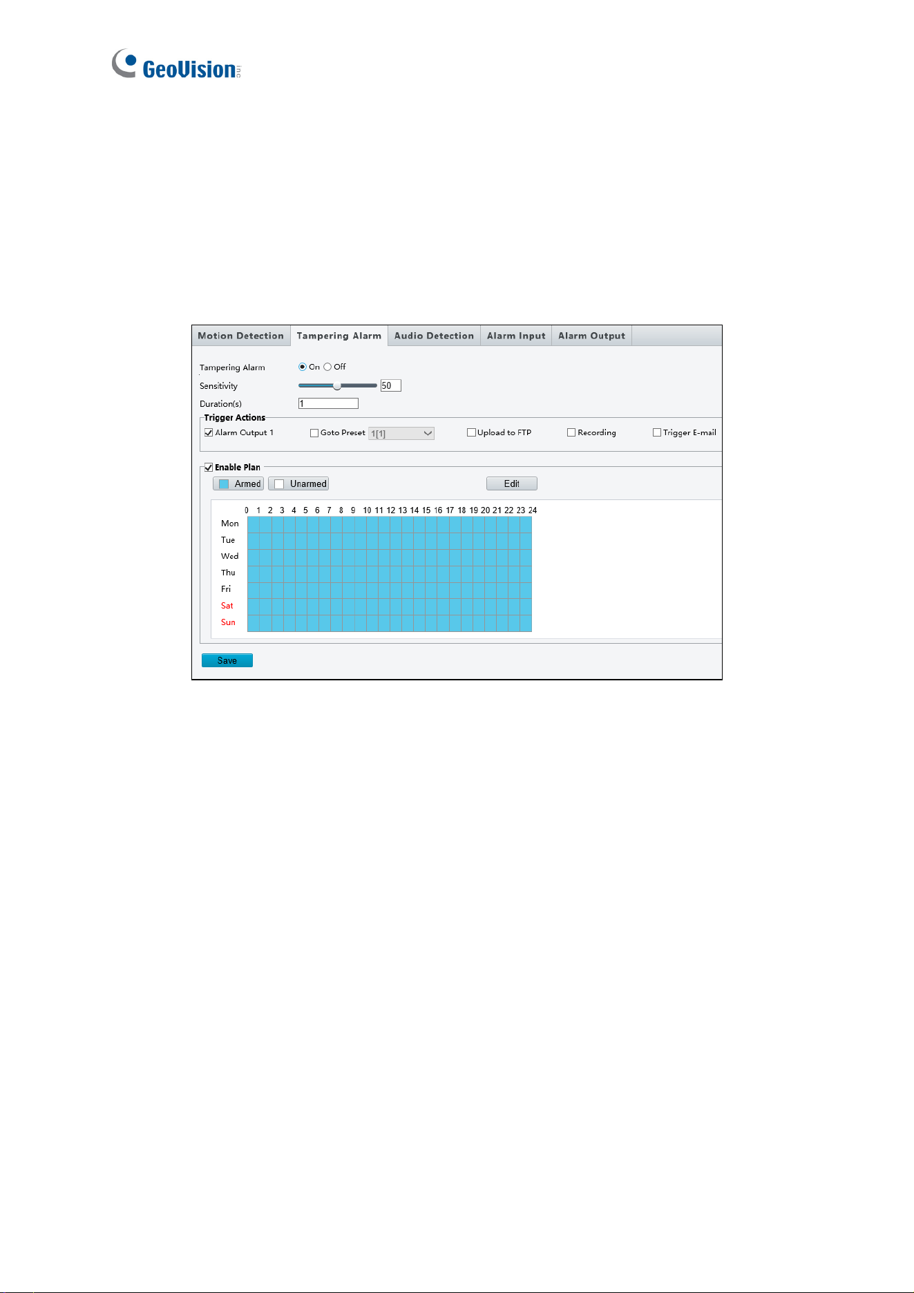
4.7.2 Tampering Alarm
Note this function is only applicable to GV-SD2722-IR / 3732-IR.
Tampering alarm is used to detect when the camera is being physically tampered with. An
alarm can be generated when the camera is moved, covered up, or out of focus.
Figure 4-39
1. Select On to enable Tampering Alarm.
2. You can use the following functions to adjust the alarm settings.
Sensitivity: Move the slider to increase or decrease detection sensitivity.
Duration: Specify the duration of the alarm after which the triggered output device
will be turned off.
3. Select the actions to be triggered by a tampering alarm and set a schedule plan if needed.
See the same functions in 4.7.1 Motion Detection for detailed instructions.
Administrator Mode
77
4
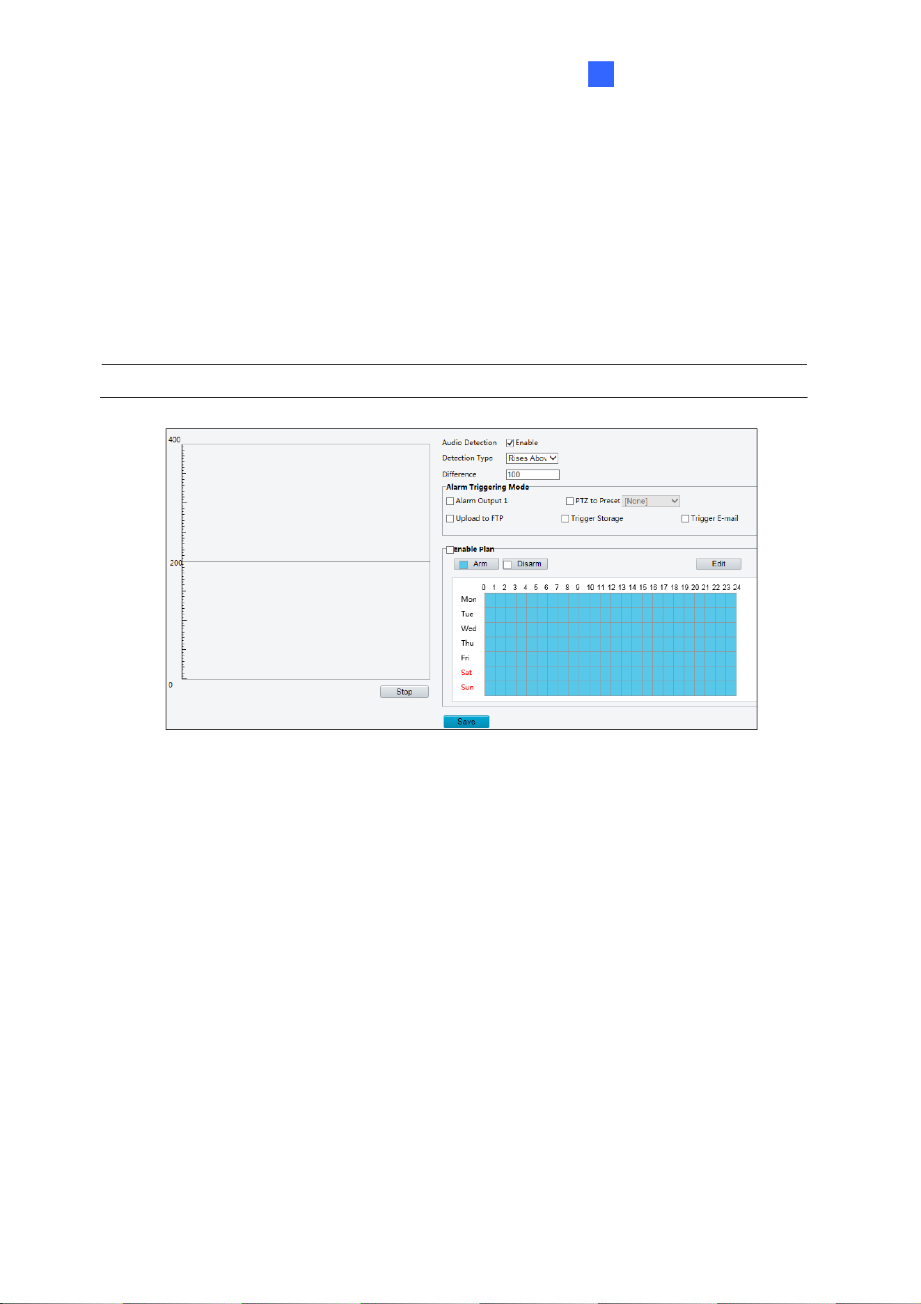
4.7.3 Audio Detection
The camera can detect for abnormal audio volume. When the rise or fall of volume exceeds
the set limit, or when the input volume reaches the threshold, the camera reports an alarm
and triggers the set actions. Make sure an audio input device is correctly connected to the
camera and audio input is enabled.
Note: To add an audio input, see 4.7.4 Alarm Input.
Figure 4-40
1. Select Enable to activate Audio Detection.
2. Select a Detection Type.
Rises Above / Sudden Rise: An alarm is reported when the rise of volume
exceeds the difference.
Falls Below / Sudden Fall: An alarm is reported when the fall of volume exceeds
the difference.
Passes / Sudden Change: An alarm is reported when the rise or fall of volume
exceeds the difference.
Threshold: An alarm is reported when the volume exceeds a threshold.
3. Set a Threshold or Difference.
Threshold: After a volume is set as the threshold, an alarm is reported when the
threshold is exceeded.

78
Difference: the difference between two volumes. When the rise or fall of volume
exceeds the difference, an alarm is reported.
4. Select the actions to be triggered by an audio alarm and set a schedule plan if needed.
Refer to 4.6.1 Motion Detection for detailed instructions
5. Click Save.
Administrator Mode
79
4
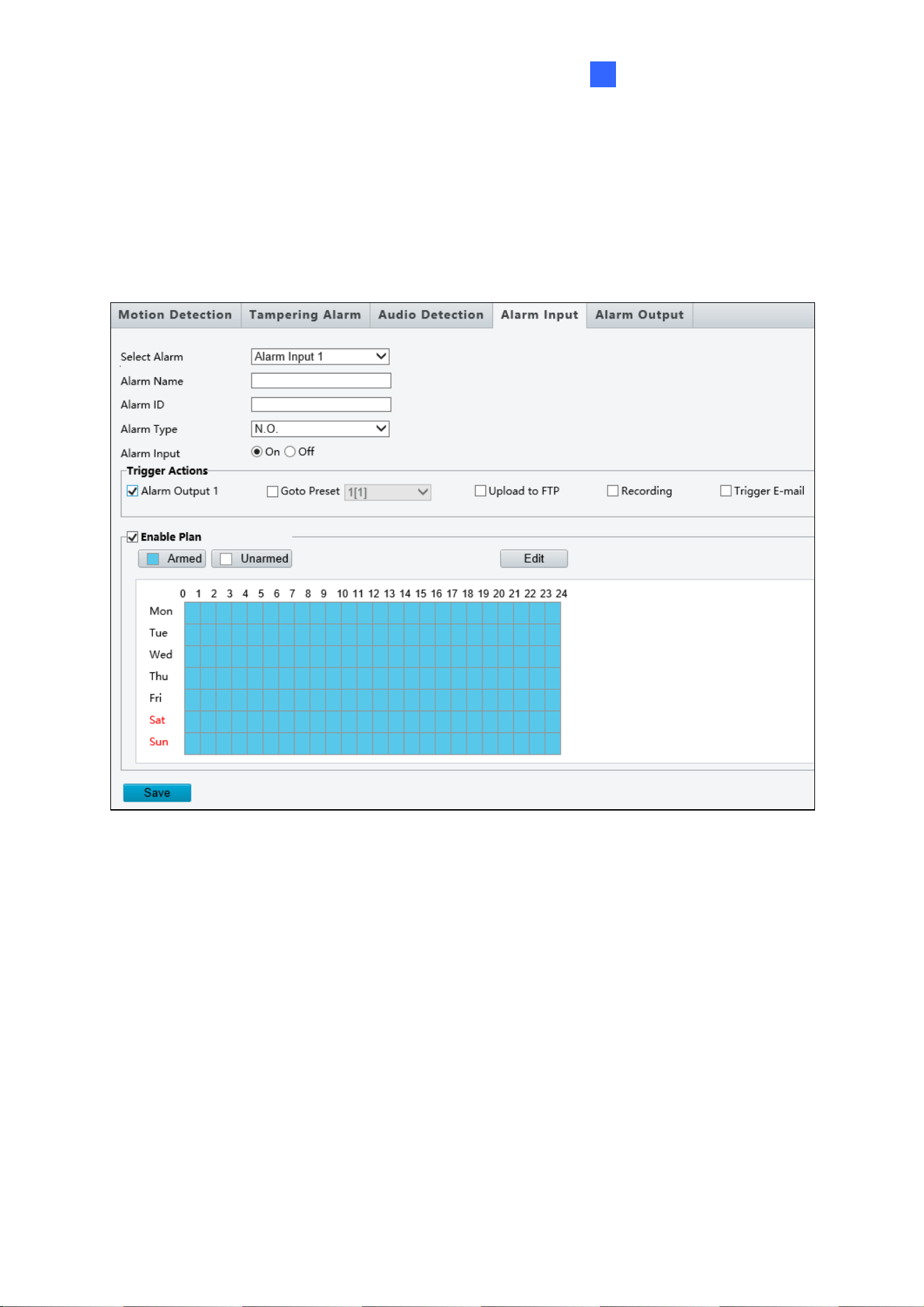
4.7.4 Alarm Input
The camera can receive alarm information from an input device.
Figure 4-41
1. Select Alarm Input 1 or Alarm Input 2 from the drop-down list.
2. Type an Alarm Name, and set an alarm ID.
3. Select Normally Open / N.O or Normally Closed / N.C according to the type of the
alarm input device.
4. Select ON next to Alarm Input.
5. Select the actions to be triggered by an input alarm and set a schedule plan if needed.
Refer to 4.6.1 Motion Detection for detailed instructions.
6. Click Save.
80
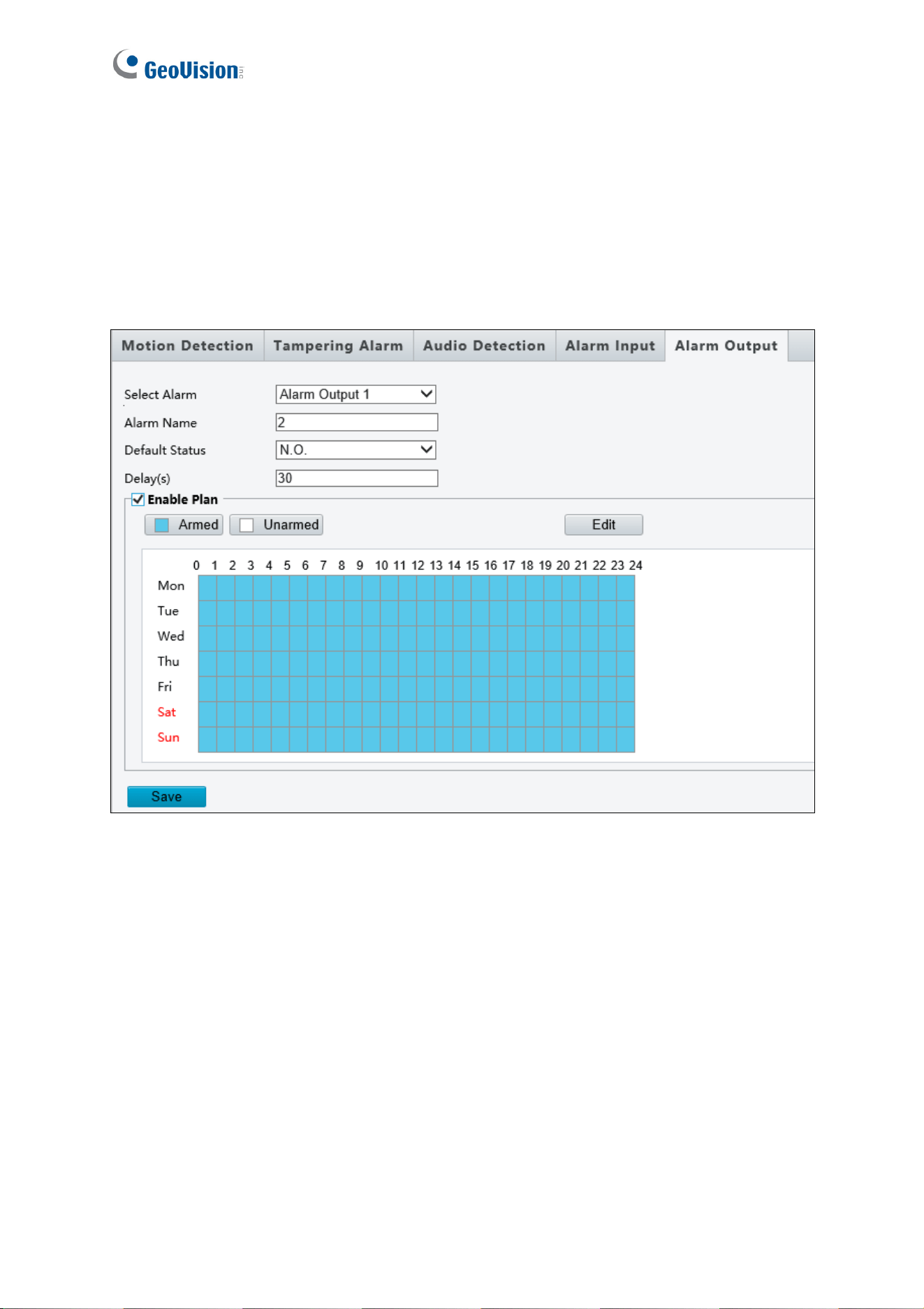
4.7.5 Alarm Output
After alarm output is triggered by a motion detection alarm, temperature alarm or input alarm,
the camera can trigger an output device.
Figure 4-42
1. Type and Alarm Name for the output device.
2. Set the status to Normally Open / N.O (default setting).
3. Set the alarm duration.
4. Set a schedule plan if needed. Refer to 4.6.1 Motion Detection for detailed instructions.
5. Click Save.
Administrator Mode
81
4
4.7.6 Capture
Note this function is only for GV-SD2322-IR.
Using the Capture function, when an alarm is triggered, the camera will automatically upload
the captured snapshots to the FTP server or send snapshots to the specified email address.
For more detailed instructions, refer to 4.3.3 Capture under Video & Audio.
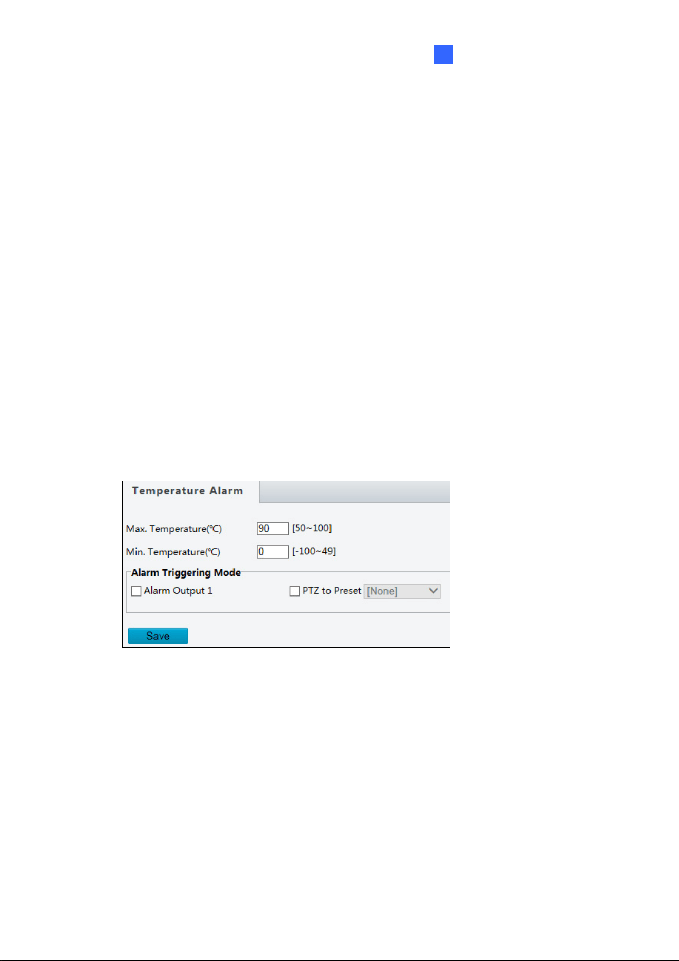
4.7.7 Temperature Alarm
Note this function is only for GV-SD2322-IR.
You can set the camera to trigger the alarm output or move to a preset point when the
camera temperature exceeds the maximum temperature or falls below the minimum
temperature.
Figure 4-43
82
4.8 Storage
This section allows you to configure memory card settings and download recorded videos.
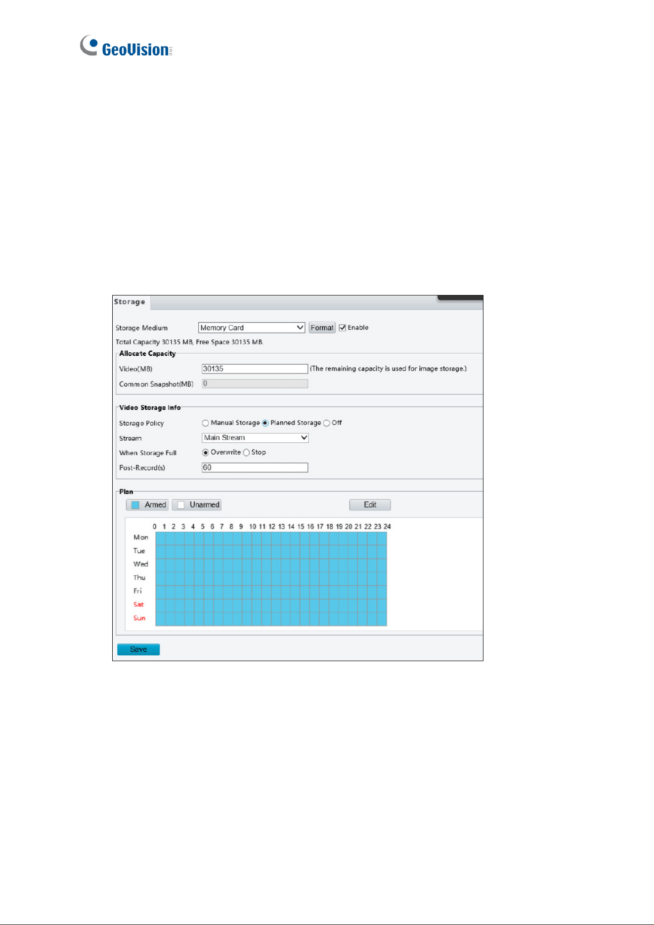
4.8.1 Storage
After inserting a memory card into the camera, you need to format the memory card using
the Format button on this page.
Figure 4-44
The following storage settings are available.
Storage Medium: Click the Format button to format the memory card before you start
recording.
Edge Storage: (The function is only for GV-SD2322-IR.) Enable or disable Round-the-
Clock recording to the memory card.

Administrator Mode
83
4
[Allocate Capacity] (The function is only for GV-SD2722-IR / SD3732-IR.)
Video: Set the storage capacity used to store recorded videos. The remaining capacity
is used for captured snapshots.
Common Snapshot: The storage capacity used to store captured snapshots.
[Video Storage Info] (The function is only for GV-SD2722-IR / SD3732-IR.)
Storage Policy: Choose the Storage Policy from one of the three options.
Manual Storage: Manually start recording.
Planned Storage: Start recording by schedule. For detailed instructions, refer to
Enable Plan section, 4.6.1 Motion Detection.
Off: Stop recording.
Stream: Select the stream you want to use for recording.
When Storage Full:
Overwrite: If there is no free space in the memory card, new data will overwrite the
existing data repeatedly.
Stop: If there is no free space in the memory card, new data will not be saved to the
memory card.
Post-Record (s): When an alarm is raised, the camera is triggered to record live video
and continues recording for the specified time after the alarm is cleared.
Enable Plan: You can set a schedule plan to enable Round-the-Clock recording. Refer
to Enable Plan section, 4.6.1 Motion Detection for detailed instructions.
84
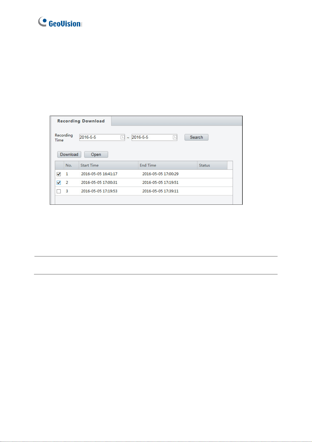
4.8.2 Recording Download
You can search and download the recorded videos stored in the memory card.
1. Select a time period to search for video, and click Search. The search results are
shown.
Figure 4-45
2. To download the videos, select the files and click Download.
3. To open the folder for storing recordings, click Open.
Note: Currently, the downloaded files will not include audio data. Audio data for recordings
downloaded will be supported in future firmware versions.
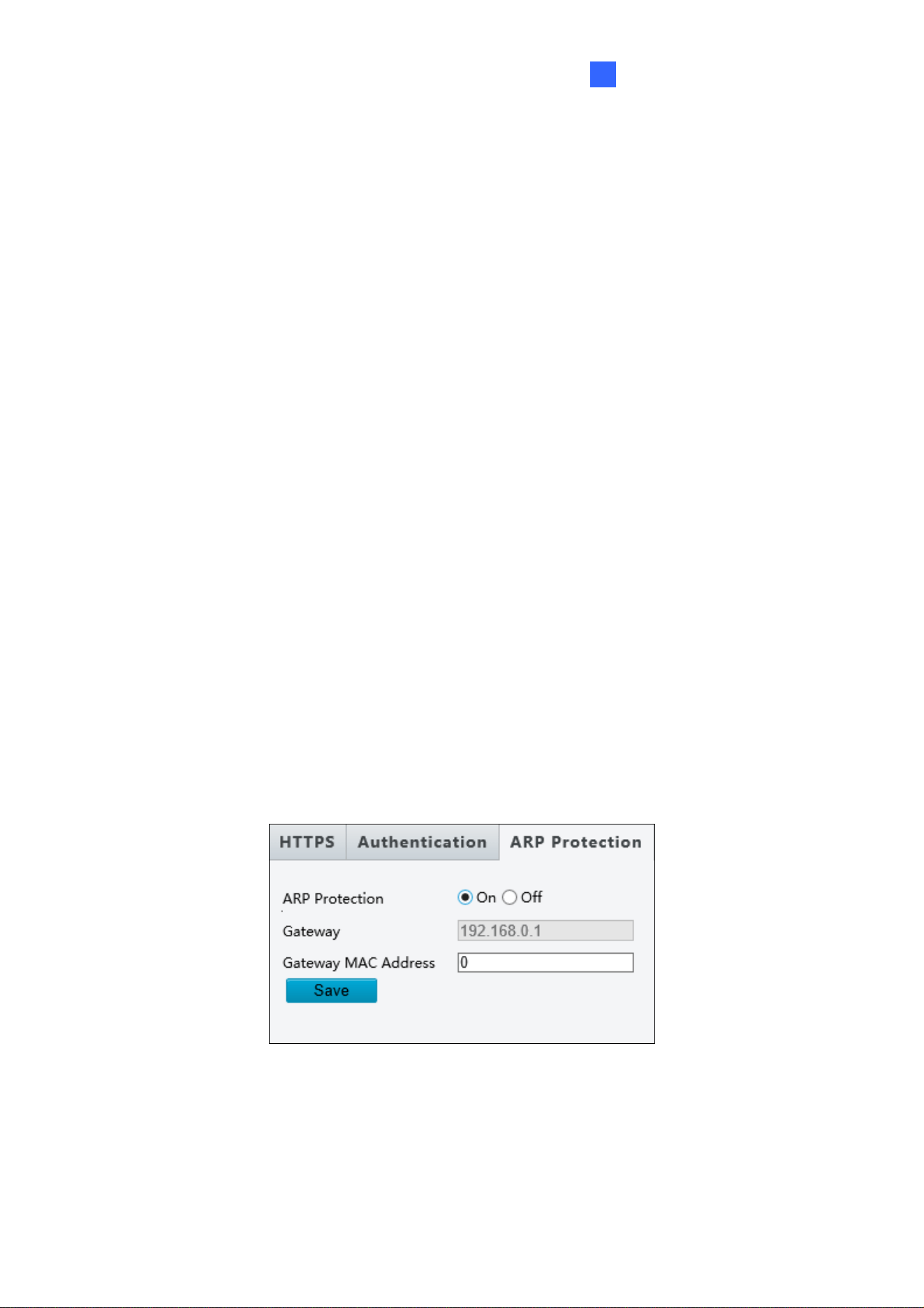
Administrator Mode
85
4
4.9 Security
Note these functions are only for GV-SD2722-IR / SD3732-IR.
This section allows you to create user accounts and set the network security settings.
4.9.1 User
There are two types of accounts: Administrator and Common User. For more detailed
instructions, refer to 4.10.3 Security.
4.9.2 Network Security
There are four of network security settings: HTTPS, RTSP Authentication, ARP Binding
and IP Address Filtering.
For HTTPS and RTSP Authentication, refer to 4.10.3 Security.
ARP Binding / ARP Protection
This function can protect the camera from ARP attacks. When the camera visits an IP of
another network segment via a gateway, it can only communicate with the MAC address
binding to the gateway address in the same segment.
Figure 4-46
1. Enable ARP Binding.
2. Type MAC Address.
3. Click Save.
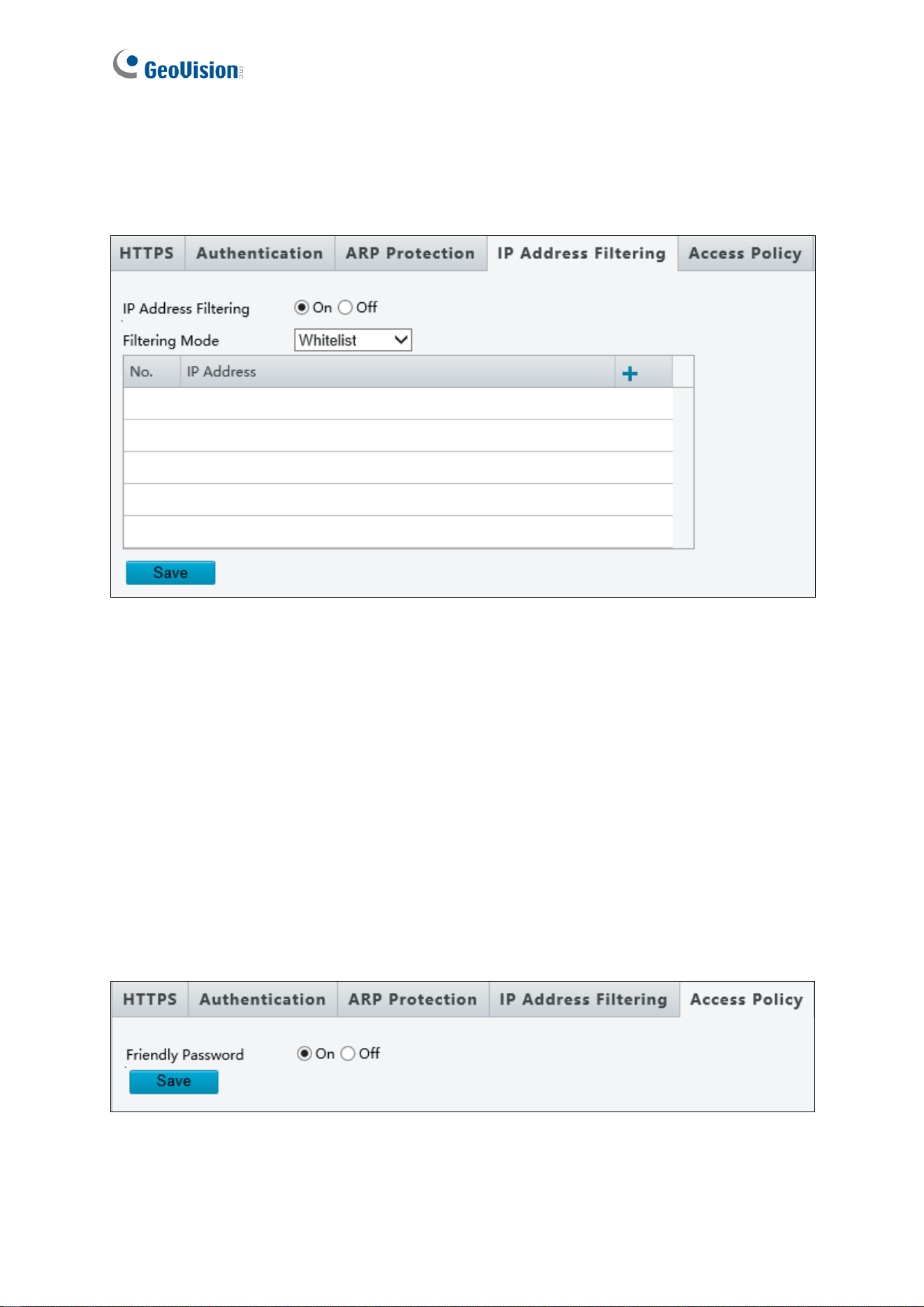
86
IP Address Filtering
You can allow or deny the access from the specified IP address to your camera.
Figure 4-47
1. Enable IP Address Filtering.
2. Choose a Filtering Mode: Allow Access / Whitelist or Deny Access.
3. Click + to add an IP address.
4. Click Save.
Access Policy
Note this function is applicable only to GV-SD2722-IR / SD3732-IR.
You can login with a weaker password by adjusting the password strength. When this option
is disabled, the camera prompts you to set up a stronger password if you attempt to login
with a weaker password.
Figure 4-48
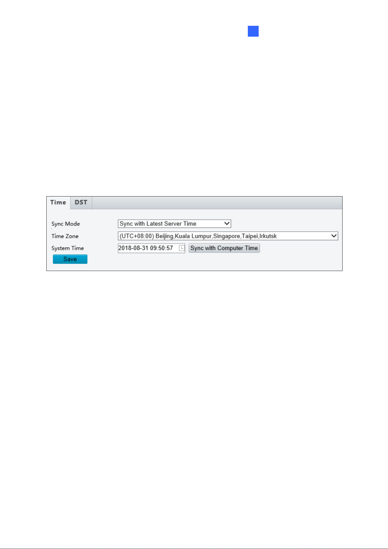
Administrator Mode
87
4
4.10 System
This section allows you to create user accounts, set the camera time, and update the
firmware.
4.10.1 Time
You can use the following methods to adjust the system time of your camera.
Figure 4-49
To manually set a time or synchronize with the computer time:
1. Enable Time Sync (For GV-SD2322-IR Only)
2. Next to Device Time, manually set the camera’s time or click Sync with Computer
Time to synchronize with the time of your PC.
3. Select a Time Zone.
4. Click Save.
To synchronize with a network time server (For GV-SD2722-IR / SD3732-IR only):
1. Enable NTP.
2. Type the IP address of the network time server next to NTP Server IP.
3. Click Save.
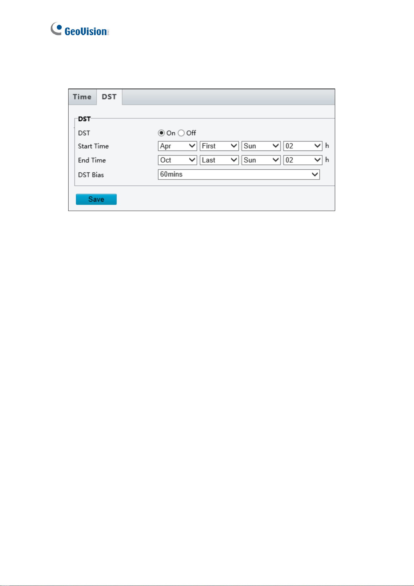
88
To adjust the camera’s time for daylight saving time:
1. Click the DST tab at the top.
Figure 4-50
2. Select Enable DST / ON.
3. Set a Start Time and End Time for the daylight saving time.
4. Select a time period for DST Bias.
5. Click Save.
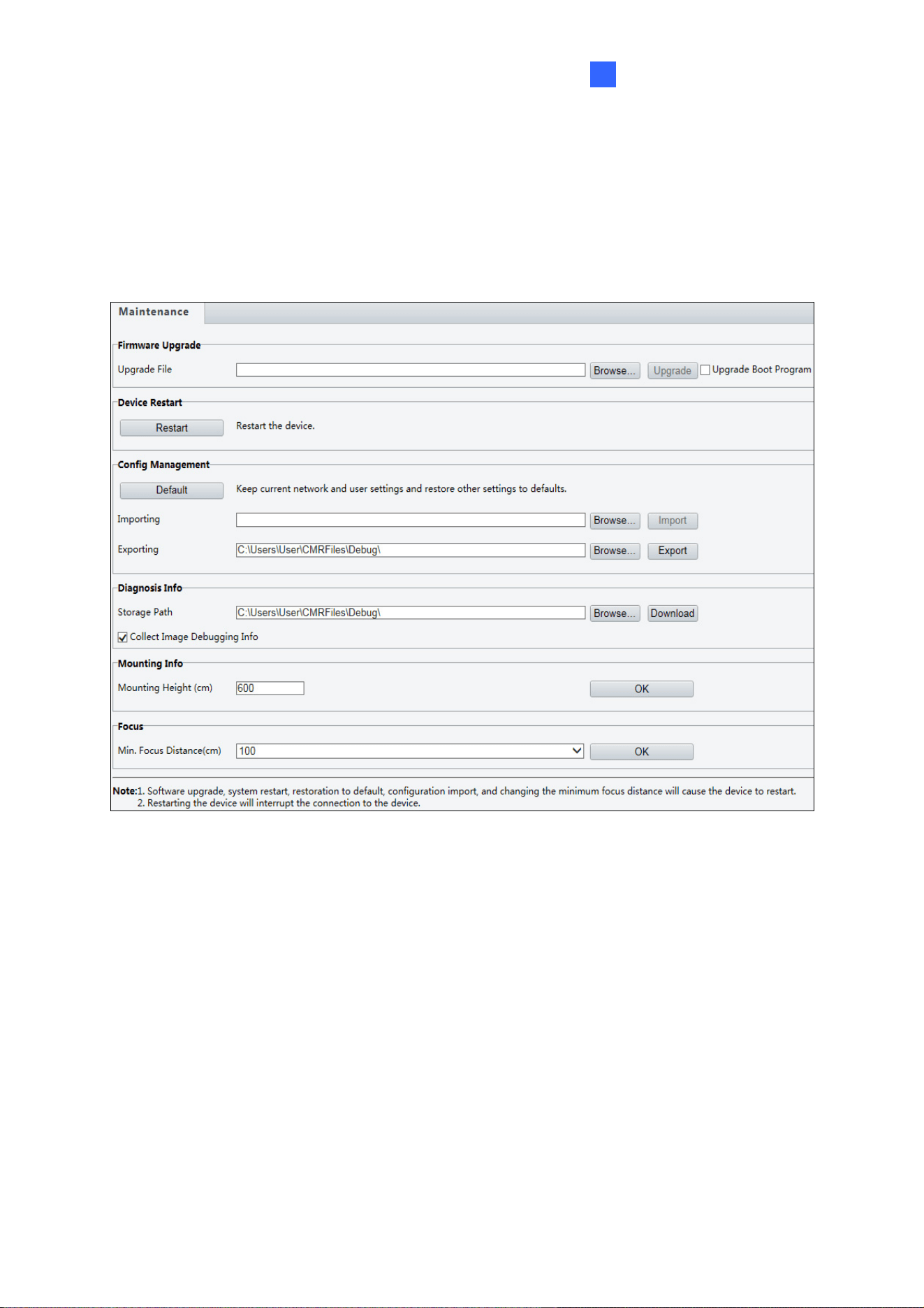
Administrator Mode
89
4
4.10.2 Maintenance
This section allows you to upgrade firmware, restart the camera, and backup/import camera
configurations.
Figure 4-51
[Firmware Upgrade / Software Upgrade].
For detailed instructions, refer to 6.1 Upgrading System Firmware and 6.1.1 Using the Web
Interface.
[Device Restart] Click Restart to restart the device after you confirm the operation.
[Config Management] Export the current configurations of the camera and save them to the
PC or an external storage medium. You can also quickly restore configurations by importing
backup configurations stored on the PC or an external storage medium back to the camera.
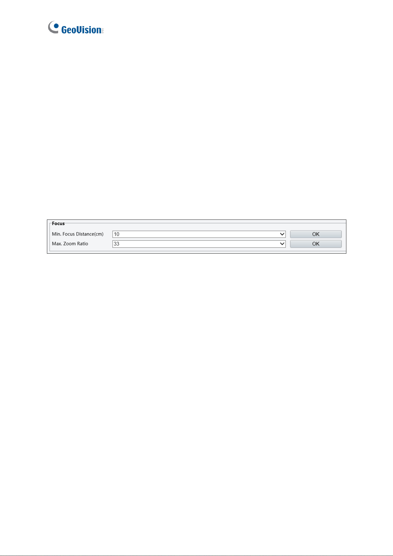
90
[Diagnosis Info] Includes logs and system configurations. You can export diagnostic
information to your PC. Click Browse to select the destination folder, and then click
Download to save the diagnostic information to the specified folder.
[Mounting Info] Type the actual height from the installed infrared dome to the ground, so
that the camera will be able to automatically adjust its infrared lamp.
[Focus] The device can adjust the speed of auto-focus according to the minimum focus
distance. It is recommended that the minimum focus distance is set shorter than the
distance between the objects and lens. For example, if the minimum focus distance is 3 m,
then the objects within 3 m from lens will be out of focus. For GV-SD2722-IR / SD3732-IR,
you can adjust zoom ratio to see the clear image when zooming in according to the
maximum zoom ratio.
Figure 4-52
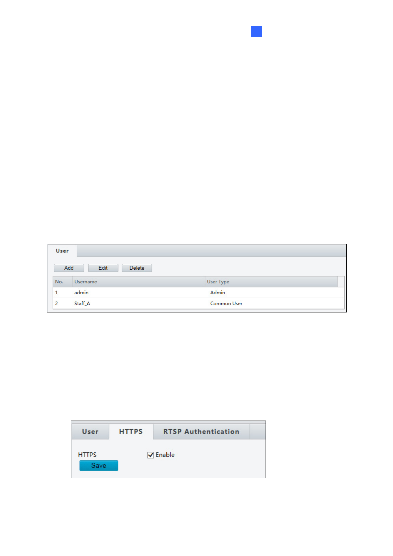
Administrator Mode
91
4
4.10.3 Security
Three tabs are available under the Security page: User, HTTPS, and RTSP Authentication.
User
There are two types of accounts: Administrator and Common User.
Administrator: The default name of the administrator is admin, which cannot be
modified. Admin has full permission and can manage all users and devices. Only one
admin account is allowed in the system.
Common Users: User only has permission to play live and recorded video. Up to 31
common users are allowed in the system.
The administrator can create new account for a common user. After the user is added
successfully, the administrator can change the password by entering the new password or
delete the user by clearing the username.
Figure 4-53
Note: Changing the username or password for a user when the user is still logged in will
force the user to log out. The user must use the new username or password to log in.
HTTPS
You can enable the Hypertext Transfer Protocol Secure (HTTPS) settings to access the
camera through a secure protocol. Click Enable and click Save.
Figure 4-54
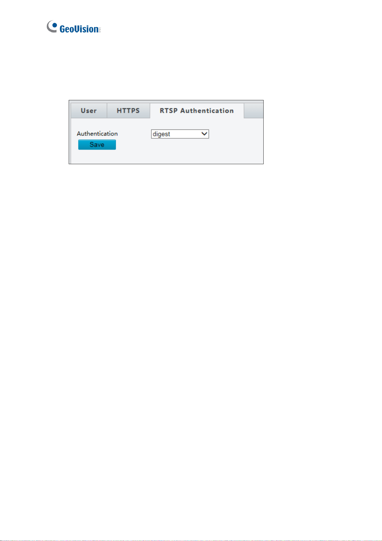
92
RTSP Authentication
RTSP (Real Time Streaming Protocol) is an application layer protocol for transmitting audio
and video. Set the authentication mode for RTSP streaming.
Figure 4-55
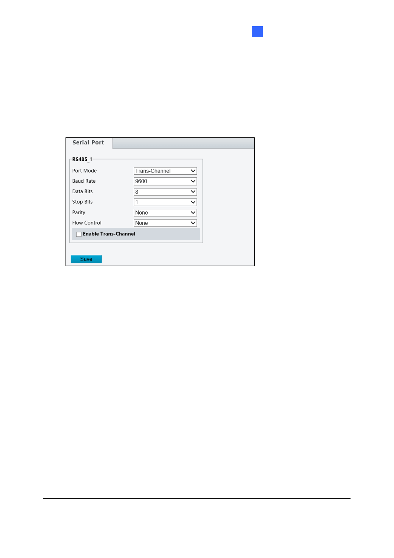
Administrator Mode
93
4
4.10.4 Ports and Device
Note this function is only applicable to GV-SD2722-IR / SD3732-IR.
Use the RS485 serial port to transmit data to the third-party device.
Figure 4-56
1. Select Trans-Channel / OSD / Local PTZ Control / Trans-Channel via ONVIF from the
Port Mode drop-down list.
Transparent Channel (Trans-Channel) / Transparent Channel (via ONVIF):
Achieve transparent data transmission between two devices by using RS485 serial
port or ONVIF.
OSD: Display information from the third-party device on the OSD.
Local PTZ Control: Control a PTZ camera through a third-party device.
2. Select Enable Trans-Channel if Trans-Channel is selected.
3. Click Save.
Note:
1. If the OSD port mode is selected, the camera receives information from the third-party
device through the RS485 serial port, translates the received information, and then
displays it on the OSD.
2. If the Local PTZ Control port mode is selected, by sending PELCO-D compliant PTZ
control commands through the RS485 port, you can control the PTZ camera without
using the PTZ control panel.

94
Chapter 5 Recording and Playback
The camera can record video and audio directly to the memory card.
Note: See Note for Recording at the beginning of the manual.
5.1 Recording
To configure the recording function, refer to the following sections
Insert the memory card into the camera -- See
1.6 Accessory Installation.
Format the memory card, create a recording schedule, set up post-recording or select
the stream for recording -- See 4.8.1 Storage.
Set up recording upon motion detection -- See 4.7.1 Motion Detection.
Set up recording upon audio detection -- See 4.7.3 Audio Detection.
Set up recording upon input trigger -- See 4.7.4 Alarm Input.
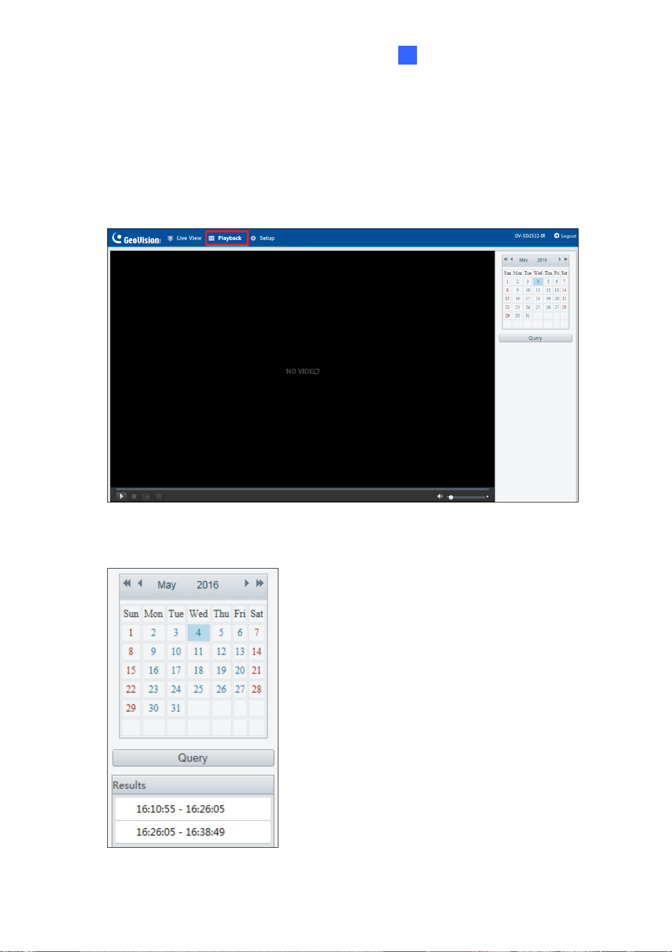
Recording and Playback
95
5
5.2 Playback from the Memory Card
You can play back the files recorded at the memory card of the camera from the Web
interface.
1. Click Playback at the top. This page appears.
Figure 5-1
2. On the right, select a date and click Query.
Figure 5-2
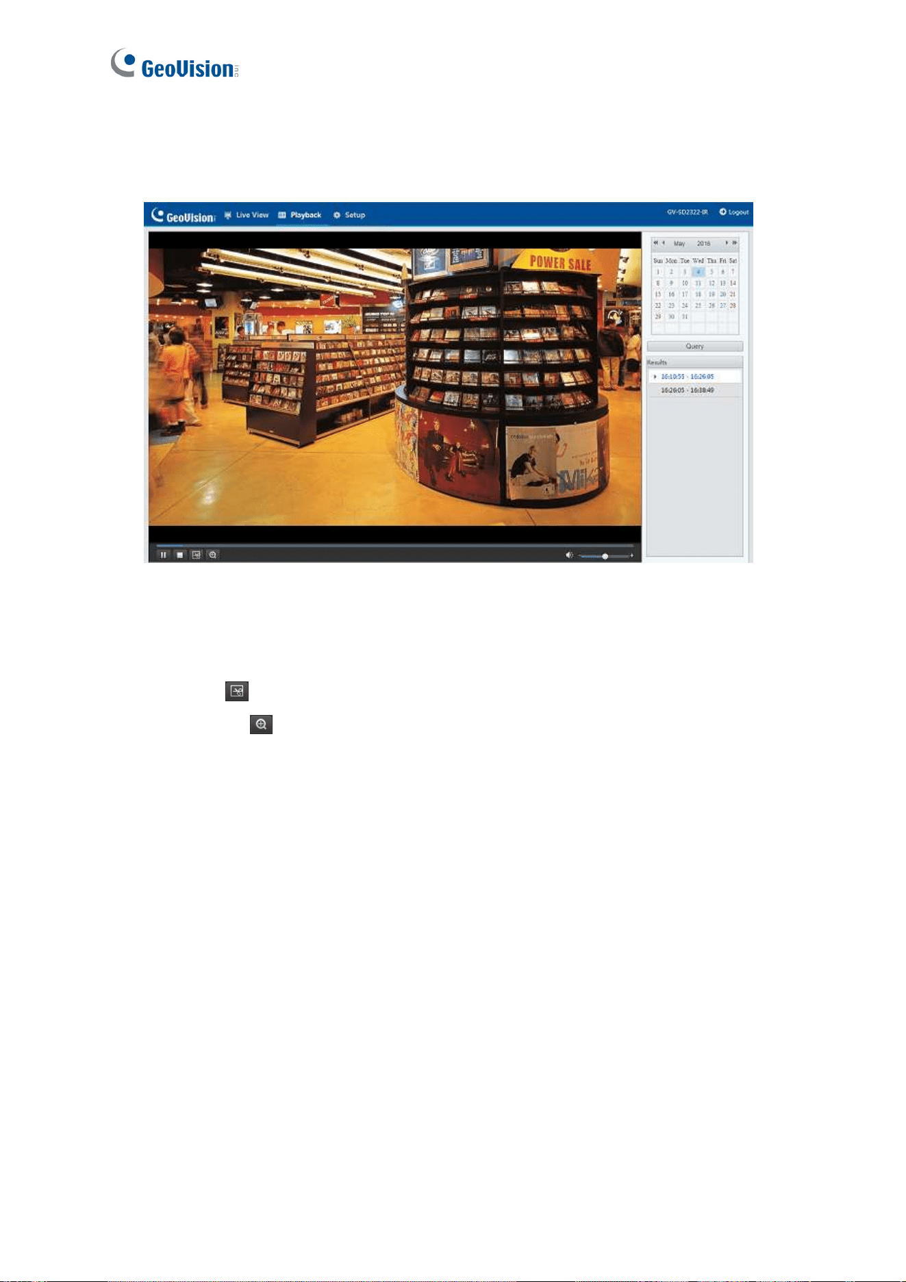
96
3. Double-click a search result to play back the recorded file. You can adjust the audio
volume at the bottom-right corner if needed.
Figure 5-3
The following functions are available:
Snapshot
: Click to capture a snapshot of the recorded video.
Digital Zoom
: Click the icon and draw a box on the camera view to digitally zoom
in.

97
Chapter 6 Advanced Applications
This chapter introduces more advanced applications.
6.1 Upgrading System Firmware
GeoVision periodically releases updated firmware on the company website. The new
firmware can be loaded into the camera using the Web interface or the
GV-IP Device Utility.
Important Notes before You Start
Before you start updating the firmware, please read these important notes:
1. If you use the GV-IP Device Utility for firmware upgrade, the computer used to upgrade
firmware must be under the same network of the camera.
2. Stop monitoring of the camera.
3. Stop the device’s connection to GV-VMS / DVR / NVR and all remote connections.
4. While the firmware is being updated, the power supply must not be interrupted.
WARNING: The interruption of power supply during updating causes not only update
failures but also damages to your camera. In this case, please contact your sales
representative and send your device back to GeoVision for repair.
5. Do not turn the power off within 10 minutes after the firmware is updated.
6. If firmware upgrade fails, you will need to restore the camera to the default settings. For
details, see 6.2 Restoring to Factory Default Settings.
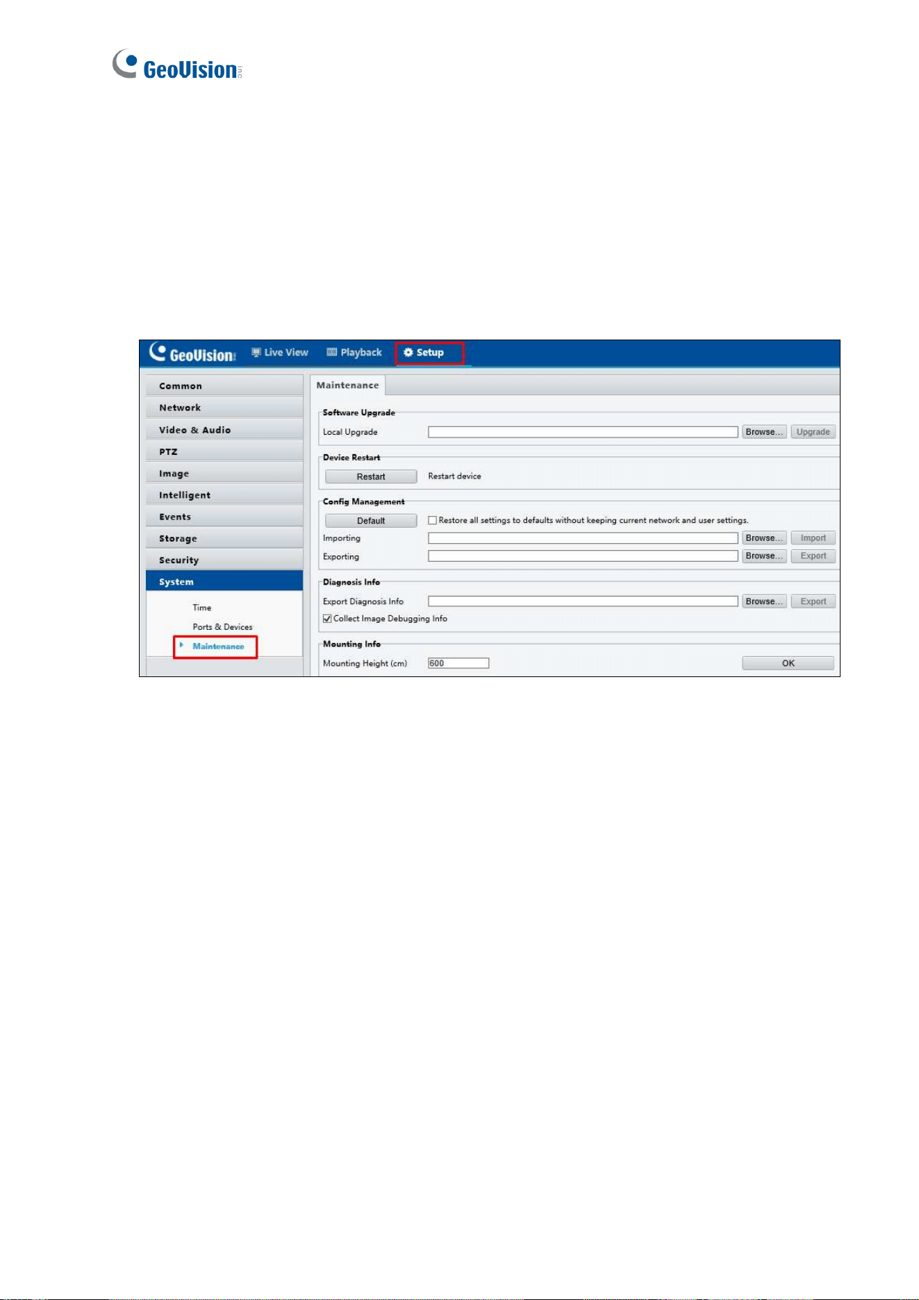
98
6.1.1 Using the Web Interface
Log into the Web interface and follow the steps below to update the firmware.
1. At the top, click Setup.
2. In the left menu, select System and select Maintenance. This page appears.
Figure 6-1
3. Click the Browse button to locate the firmware file (.zip) saved at your local computer.
4. Optionally select Upgrade Boot Program to reboot the camera after a successful
upgrade.
5. Click the Upgrade button to process the upgrade.
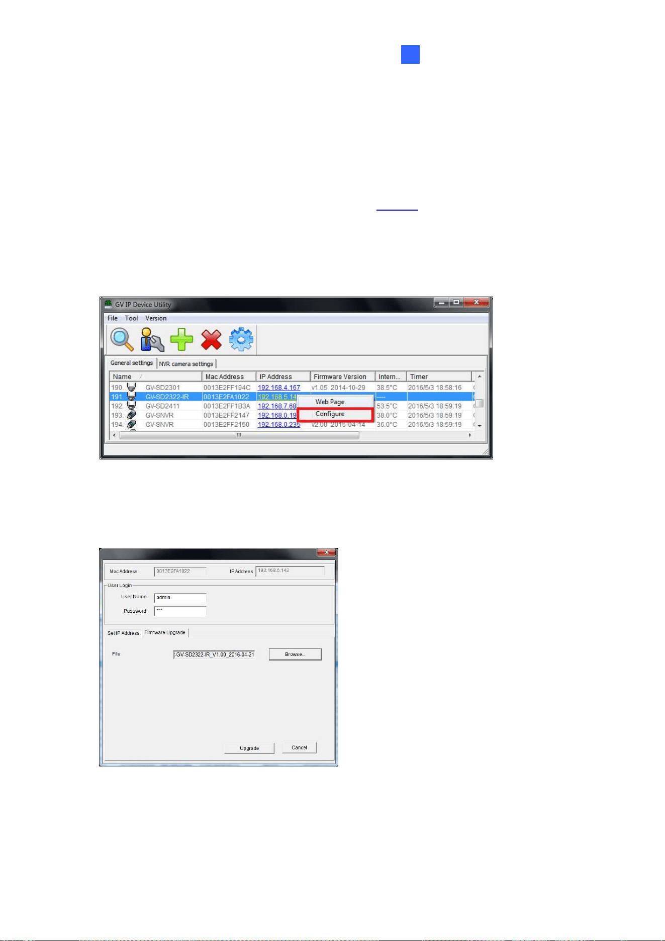
Advanced Applications
99
6
6.1.2 Using the GV-IP Device Utility
You can upgrade the camera firmware using the GV-IP Device Utility. Note the computer
used to upgrade firmware must be under the same network of the camera.
1. Download GV-IP Device Utility from the company
website
. Then follow the onscreen
instructions to install the program.
2. Double-click the GV IP Device Utility icon created on your desktop.
3. Click the camera in the list and select Configure.
Figure 6-2
5. Type the camera’s user name and password to login.
6. Click the Firmware Upgrade tab. This dialog box appears.
Figure 6-3
7. Click the Browse button to locate the firmware file (.zip) saved at your local computer.
8. Click Upgrade to start upgrading the firmware.
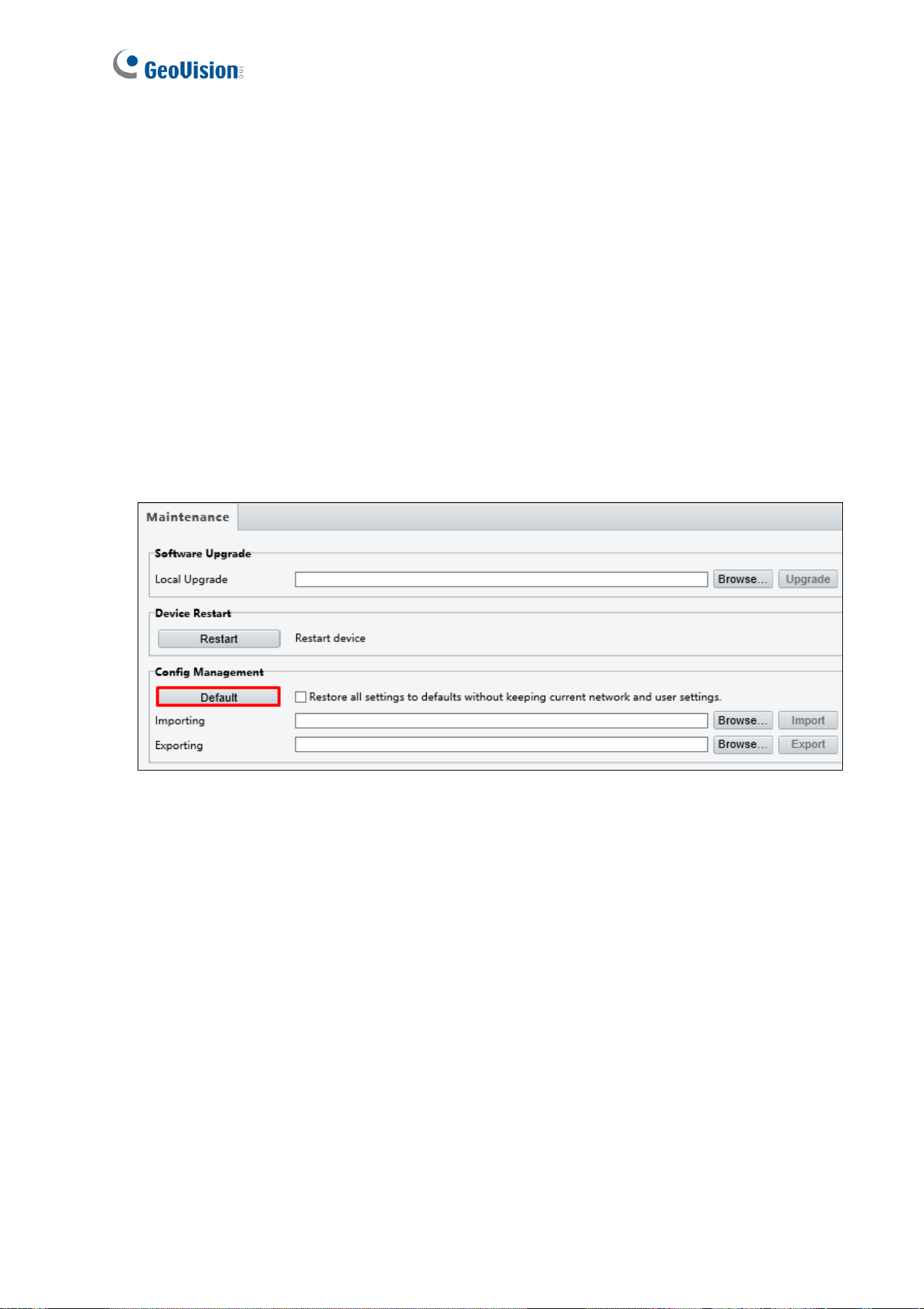
100
6.2 Restoring to Factory Default Settings
If for any reason the camera is not responding correctly, you can restore the camera back
to its factory default settings using the Web interface or the Default Button.
6.2.1 Using the Web Interface
To restore to default settings using the Web interface:
1. At the top, click Setup.
2. In the left menu, select System and select Maintenance.
3. Under the Config Management section, click the Default button.
Figure 6-4
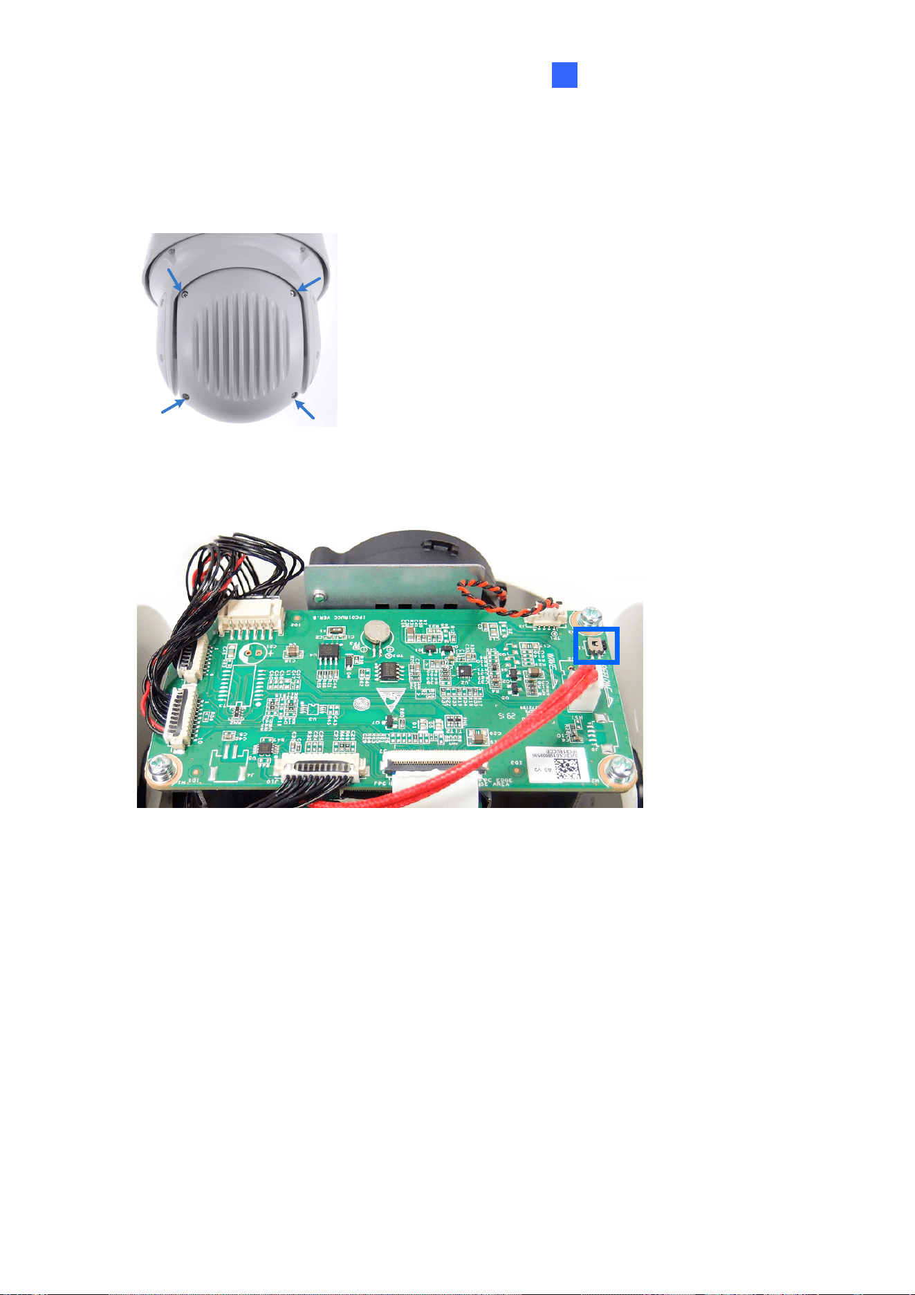
Advanced Applications
101
6
6.2.2 Directly on the Camera
1. Unscrew the back cover of the camera.
Figure 6-5
2. Press and hold the default button for about 30 seconds.
Figure 6-6
3. When the camera rotates twice, the process of loading default is completed and the
camera robots automatically.
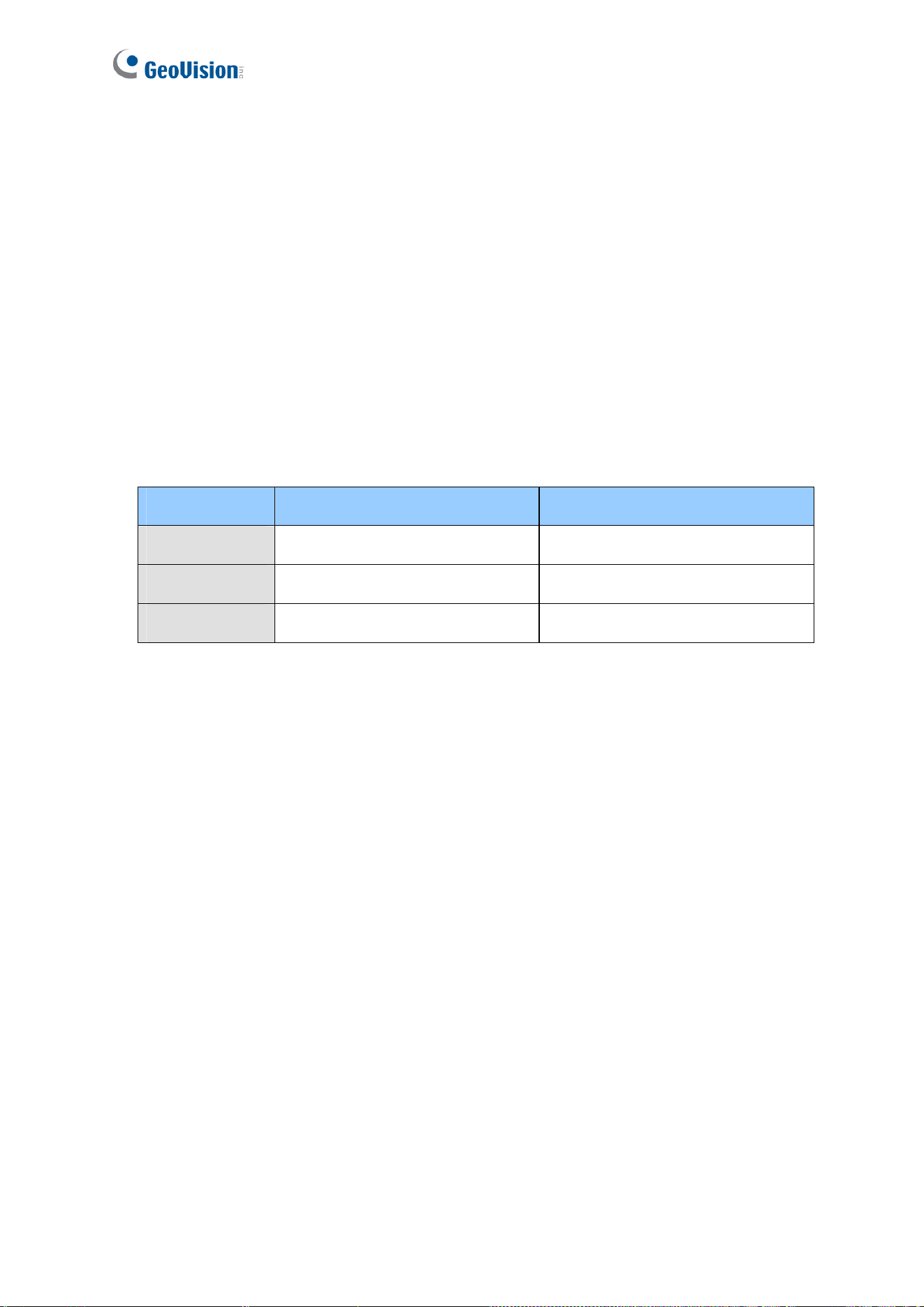
102
Chapter 7 VMS / DVR / NVR
Configurations
The GV-VMS / DVR / NVR provides a complete video management solution, including video
viewing, recording, playback, alert settings, and more. The integration specifications are
listed below:
The compatible GV-VMS / DVR / NVR versions are listed below:
Camera Model Compatible GV-DVR / NVR Compatible GV-VMS
GV-SD2322-IR V8.7.0.0 or later V15.10.1.0 with patch files or later
GV-SD2722-IR V8.7.4.0 with patch files or later V17.1.0.100 or later
GV-SD3732-IR V8.7.1.0 with patch files or later V15.11.1.0 with patch files or later
When connecting to other applications, an IP camera supports remote connections
of up to 40 Mbps in throughout and a maximum of 20 streams.
When a GV-IP Speed Dome is connected to IE browser or any other applications, it
takes up 1 stream; when it is connected to GV-VMS / DVR / NVR, t takes up 2
streams.
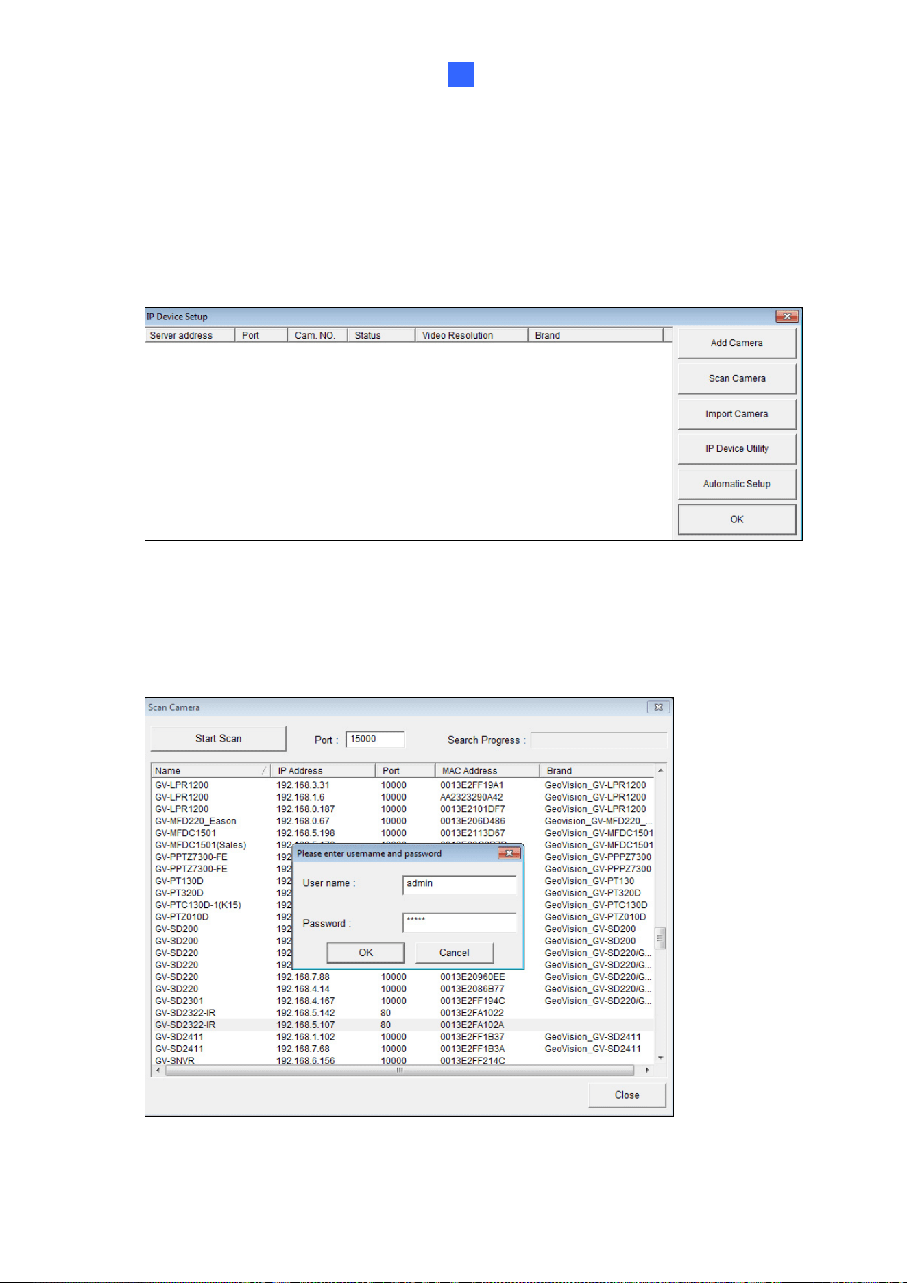
VMS / DVR / NVR Configurations
103
7
7.1 Setting up IP Cameras on GV-DVR / NVR
To set up the camera on the GV- DVR / NVR, follow these steps:
1. On the main screen, click the Configure button, select System Configure, select
Camera Install and click IP Camera Install. This dialog box appears.
Figure 7-1
2. To automatically set up the camera, click Scan Camera to detect any camera on the
LAN.
3. Double-click the camera and type the user name and password of the camera.
Figure 7-2
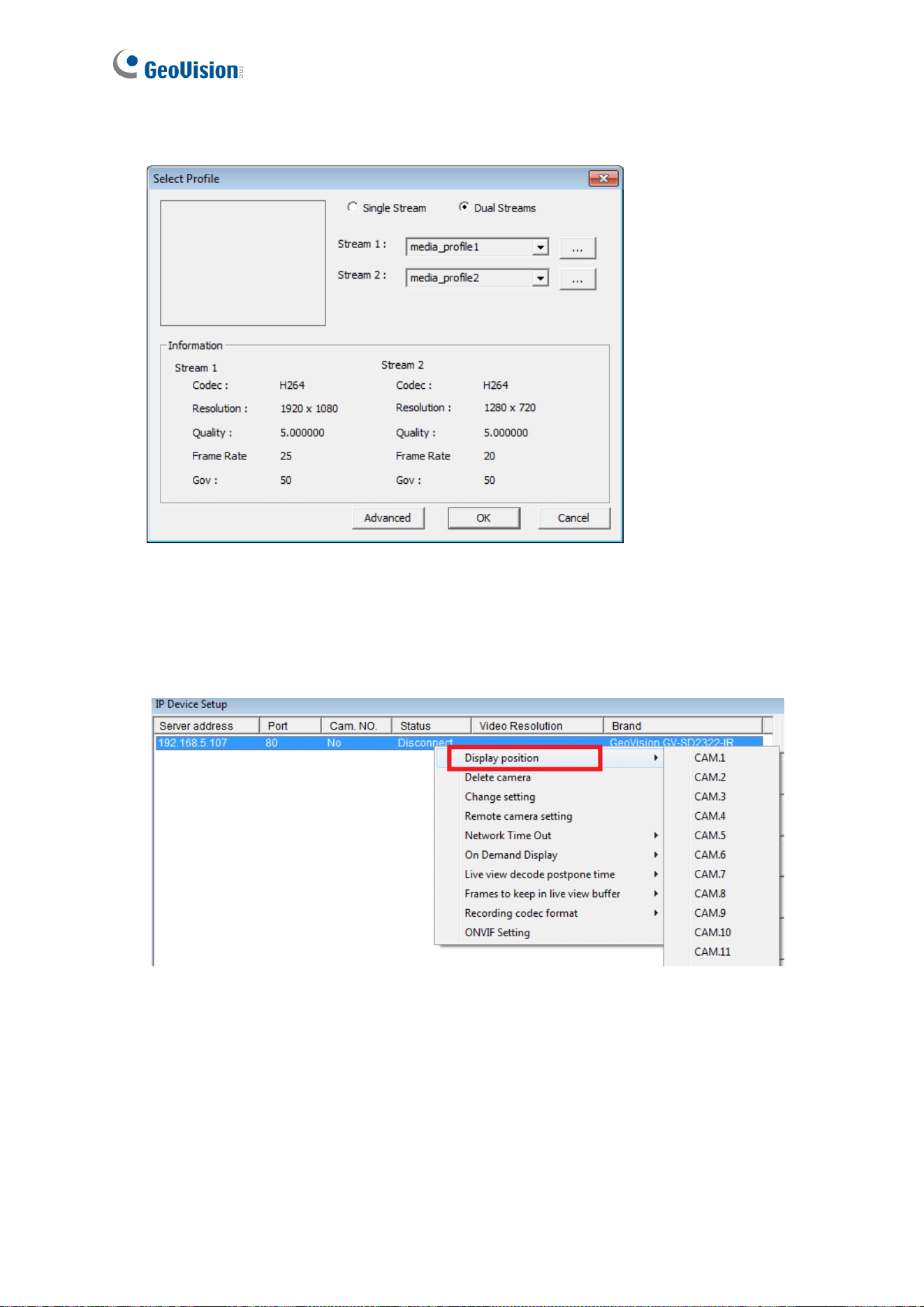
104
4. Click OK. This dialog box appears.
Figure 7-3
5. Click OK. The camera is added to the connection list.
6. Click the listed camera and select Display position to map the camera to a channel on
the GV-DVR / NVR.
Figure 7-4
7. The Statue column should display “Connected”. Click OK.
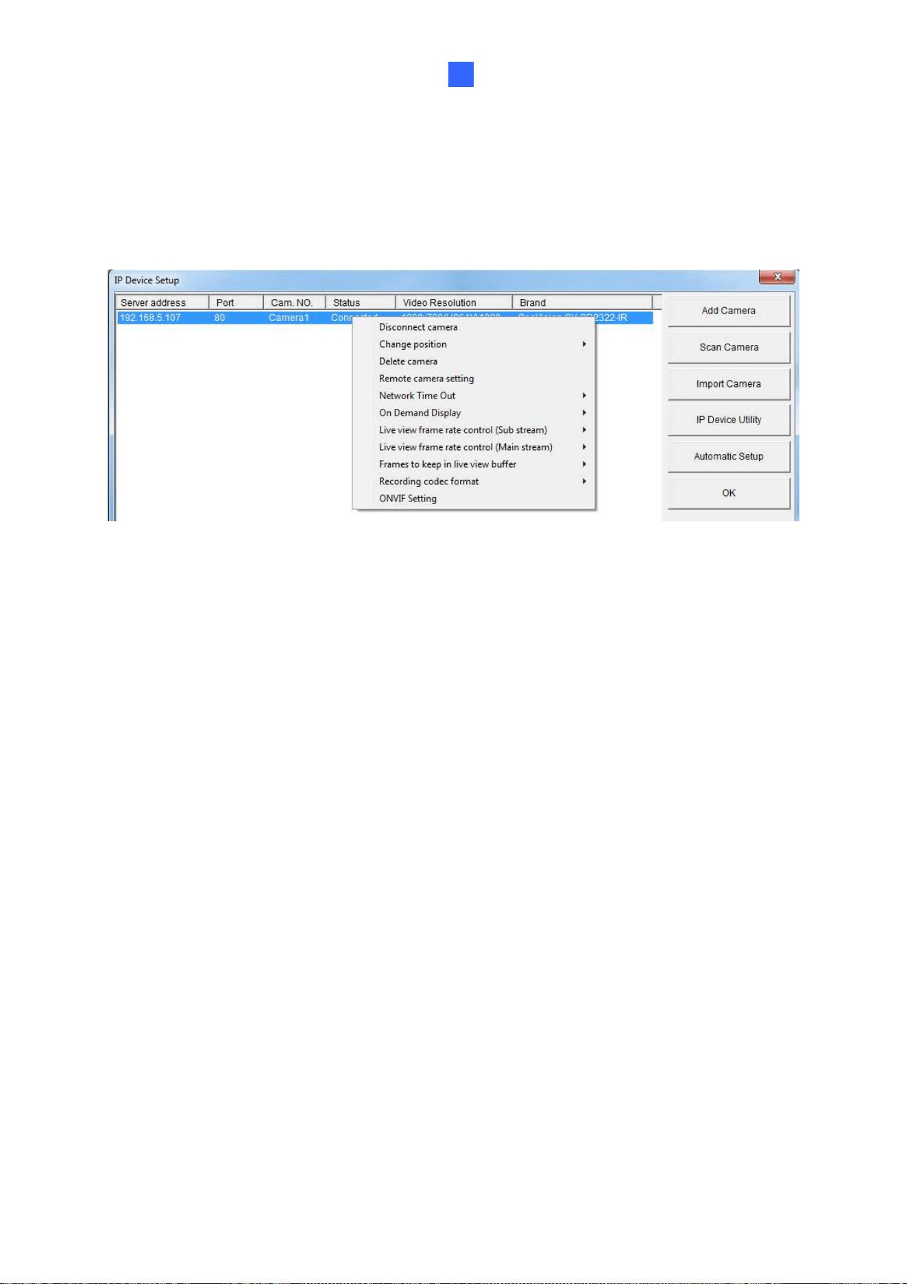
VMS / DVR / NVR Configurations
105
7
7.1.1 Customizing the Basic Settings on GV-DVR / NVR
After the camera is connected and assigned with a display position, you can configure the
camera’s settings such as frame rate, codec type and resolution. Right-click the desired
camera to see the following list of options:
Figure 7-5
Network Time Out: When network disconnection exceeds the specified time period, the
camera status will be displayed as Connection Lost.
On-Demand Display: Enables automatic switching between main stream and sub
stream based on the size of camera image on screen.
Live-view frame rate control (Sub / Main): Sets the frame rate of the stream to help
reduce the CPU usage. If you have set the codec to be MJPEG, select the number of
frames to allow in a second. If the codec selected is H.265 or H.264, select one of the
following options:
Maximum Live-view Frame Rate: View the video at the maximum frame rate
possible.
Live-view Key Frame only: You can choose to view the key frames of the videos
only instead of all frames on the live view. This option is related to the GOP setting
of the IP camera. For example, if the GOP value is set to 30, there is only one key
frame among 30 frames.
Frames to keep in live view buffer: Specifies the number of frames to keep in the live
view buffer.
Recording Codec Format: Select the codec to record in.
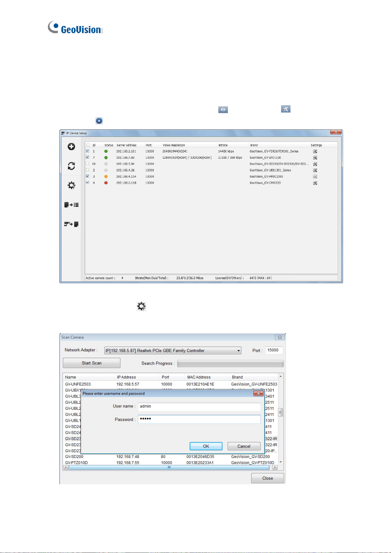
106
7.2 Setting Up IP Cameras on GV-VMS
Follow the steps below to manually connect your camera to GV-VMS.
1. To access the IP Device Setup page, click Home
, select Toolbar , click
Configure
and select Camera Install.
Figure 7-6
2. Click Automatic Setup
.
3. Double-click the camera and type the user name and password of the camera.
Figure 7-7
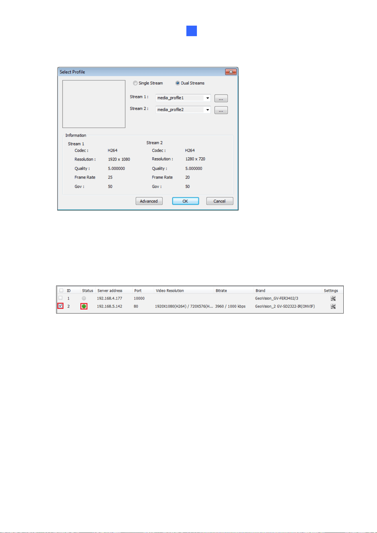
VMS / DVR / NVR Configurations
107
7
4. Click OK. This dialog box appears.
Figure 7-8
5. Click OK to add the camera to the list.
6. To connect the added camera, click the box besides the ID column. Upon successful
connection, the Status icon shows green, with the video resolution and bit rate being
displayed in the corresponding columns.
Figure 7-9

108
Appendix
A. RTSP Multicast Protocol Support
The camera can support RTSP multicast protocol for both video and audio streaming.
You can use the following RTSP multicast command to access the camera image:
Stream 1:rtsp://<IP of the camera>/multicast/video1
Stream 2:rtsp://<IP of the camera>/multicast/video2
For example, rtsp://192.168.4.115/multicast/video1